EP4393669A1 - Stapler - Google Patents
Stapler Download PDFInfo
- Publication number
- EP4393669A1 EP4393669A1 EP23219671.7A EP23219671A EP4393669A1 EP 4393669 A1 EP4393669 A1 EP 4393669A1 EP 23219671 A EP23219671 A EP 23219671A EP 4393669 A1 EP4393669 A1 EP 4393669A1
- Authority
- EP
- European Patent Office
- Prior art keywords
- clinch
- staple
- driving
- table link
- regulation
- Prior art date
- Legal status (The legal status is an assumption and is not a legal conclusion. Google has not performed a legal analysis and makes no representation as to the accuracy of the status listed.)
- Granted
Links
Images



Classifications
-
- B—PERFORMING OPERATIONS; TRANSPORTING
- B27—WORKING OR PRESERVING WOOD OR SIMILAR MATERIAL; NAILING OR STAPLING MACHINES IN GENERAL
- B27F—DOVETAILED WORK; TENONS; SLOTTING MACHINES FOR WOOD OR SIMILAR MATERIAL; NAILING OR STAPLING MACHINES
- B27F7/00—Nailing or stapling; Nailed or stapled work
- B27F7/17—Stapling machines
- B27F7/30—Driving means
- B27F7/36—Driving means operated by electric power
-
- B—PERFORMING OPERATIONS; TRANSPORTING
- B25—HAND TOOLS; PORTABLE POWER-DRIVEN TOOLS; MANIPULATORS
- B25C—HAND-HELD NAILING OR STAPLING TOOLS; MANUALLY OPERATED PORTABLE STAPLING TOOLS
- B25C5/00—Manually operated portable stapling tools; Hand-held power-operated stapling tools; Staple feeding devices therefor
- B25C5/02—Manually operated portable stapling tools; Hand-held power-operated stapling tools; Staple feeding devices therefor with provision for bending the ends of the staples on to the work
- B25C5/0221—Stapling tools of the table model type, i.e. tools supported by a table or the work during operation
-
- B—PERFORMING OPERATIONS; TRANSPORTING
- B27—WORKING OR PRESERVING WOOD OR SIMILAR MATERIAL; NAILING OR STAPLING MACHINES IN GENERAL
- B27F—DOVETAILED WORK; TENONS; SLOTTING MACHINES FOR WOOD OR SIMILAR MATERIAL; NAILING OR STAPLING MACHINES
- B27F7/00—Nailing or stapling; Nailed or stapled work
- B27F7/17—Stapling machines
- B27F7/19—Stapling machines with provision for bending the ends of the staples on to the work
Definitions
- the present disclosure relates to a stapler that binds a sheet bundle with a staple.
- a convex portion of a fixing plate is slid along a guide groove, and an inclined surface of the fixing plate moved to a position corresponding to a thickness of the sheet bundle engages with a fixing pin of a table link that moves a binding table in a wedge shape.
- leg portions of the staple penetrating the sheet bundle are bent toward the sheet bundle by an operation of the clincher portion.
- the excess of an operation stroke of the clincher portion that bends the leg portions is absorbed by deformation of the table link. That is, the table link is deformed in a clinching operation.
- FIGS. 1A , 1B , and 1C are side views illustrating an example of a stapler according to the present embodiment
- FIGS. 1A and 1B illustrate an internal configuration of a stapler 1
- FIG. 1A illustrates an internal structure through a lock plate 30 to be described later.
- FIG. 2 is a perspective view illustrating an example of the stapler according to the present embodiment.
- the stapler 1 includes a main body portion 2 and table links 3 movably supported by the main body portion 2.
- the stapler 1 further includes the lock plates 30 for moving the table links 3 and clamp lock links 31 for moving the lock plates 30.
- a cartridge 10 in which a staple (not illustrated) is accommodated is detachably attached to the main body portion 2.
- the main body portion 2 includes a driving portion 4 that drives a staple (not illustrated) accommodated in the cartridge 10 into a sheet bundle P. Further, the main body portion 2 includes a first table 20 for sandwiching the sheet bundle P.
- the first table 20 is constituted by a portion facing one end portion of the table link 3 in a housing 21 of the main body portion 2.
- the first table 20 includes a part of the housing 21 when the first table 20 is attached to the main body portion 2 and a part of the cartridge 10 exposed to the housing 21, and a passage opening 20a through which a staple (not illustrated) driven into by the driving portion 4 passes is exposed.
- the driving portion 4 includes a driver (not illustrated) for driving a staple, a mechanism for driving the driver, and a passage through which the staple driven by the driver passes in the cartridge 10.
- a clinch portion 5 for bending leg portions of a staple (not illustrated) penetrating the sheet bundle P is attached to the table link 3.
- a second table 32 for sandwiching the sheet bundle P is attached to the table link 3.
- the clinch portion 5 and the second table 32 are attached to one end side of the table link 3 at positions where the clinch portion 5 and the second table 32 face the driving portion 4 and the first table 20.
- the clinch portion 5 is attached at a position where the clinch portion 5 faces the passage opening 20a.
- the other end side of the table link 3 is rotatably supported on the main body portion 2 by a shaft 33.
- the lock plate 30 includes a regulation portion 30a that abuts against the table link 3.
- the regulation portion 30a moves along a second direction intersecting with the first direction toward and away from the clinch portion 5.
- the lock plate 30 is supported by the main body portion 2 so as to be movable along the second direction indicated by arrows B1 and B2.
- the regulation portion 30a moves from the standby position to push the abutting portion 34 of the table link 3 and rotates the table link 3 about the shaft 33 in cooperation with the urging force of the urging member 3a, thereby moving the clinch portion 5 and the second table 32 in the arrow A1 direction toward the driving portion 4 and the first table 20.
- the regulation portion 30a moves the clinch portion 5 and the second table 32 in the arrow A2 direction away from the clinch portion 5 along the second direction intersecting the first direction in which the clinch portion 5 and the second table 32 are separated from and brought into contact with the driving portion 4 and the first table 20.
- the regulation portion 30a regulates the movement of the table link 3 in the first direction and regulates the movement of the clinch portion 5 in the arrow A2 direction away from the driving portion 4 in a state where the position of the regulation portion 30a abutting against the abutting portion 34 of the table link 3 is changed according to the distance between the clinch portion 5 and the driving portion 4 by moving in the second direction.
- FIG. 3A is a perspective view of the stapler illustrating an example of a drive unit
- FIGS. 3B and 3C are perspective views of a main part illustrating the example of the drive unit
- FIG. 3D is a front view of a main part illustrating the example of the drive unit.
- the drive shaft 61 is provided with the drive gear 65 in the vicinity of a center thereof in an extending direction, and the driver return cam 64, the driver clinch cam 63, and the clamp cam 62 are provided in this order from the drive gear 65 on one side of the drive shaft 61 across the drive gear 65.
- the driver clinch cam 63 and the clamp cam 62 are provided in this order from the drive gear 65 on the other side of the drive shaft 61 across the drive gear 65.
- the drive shaft 61 is supported by one frame 22 via the bearing portion 63b of one driver clinch cam 63 on one end side thereof in the extending direction.
- the drive shaft 61 is supported by the other frame 22 via the bearing portion 63b of the other driver clinch cam 63 on the other end side thereof in the extending direction. Accordingly, the drive shaft 61 is supported by the frames 22 on both sides thereof sandwiching the drive gear 65.
- the drive unit 6 includes a first intermediate gear 66 that meshes with the gear 60a of the motor 60, and a second intermediate gear 67 that meshes with the first intermediate gear 66 and the drive gear 65.
- the distance between the clinch portion 5 and the driving portion 4 is shorter than when the number of sheets to be bound by a staple is large or when the sheet is thick.
- a distance L1 from the position where the regulation portion 30a abuts the abutting portion 34 to the clinch portion 5 is longer than a distance L2 when the distance between the clinch portion 5 and the driving portion 4 is long, as illustrated in FIGS. 5A , 5B , and 5C .
- the motor 60 further rotates so that a staple (not illustrated) is driven into the sheet bundle P by an operation of the driving portion 4.
- the distance L2 from the position where the regulation portion 30a abuts against the abutting portion 34 to the clinch portion 5 is shorter than when the number of sheets to be bound by a staple is small or when the sheet is thin as illustrated in FIGS. 4A , 4B , and 4C .
- a force to rotate the table link 3 in the arrow A2 direction is applied by a reaction force of a force with which the clinch portion 5 presses the leg portion.
- the operation of the table link 3 that sandwiches the sheet bundle P and the operation of the clinch portion 5 that bends the leg portion of the staple are interlocked with each other, and the rotation of the motor 60 continues in a state where the sheet bundle P is sandwiched between the first table 20 and the second table 32.
- the distance L1 from the position where the regulation portion 30a abuts against the abutting portion 34 to the clinch portion 5 is longer than the distance L2 when the number of sheets to be bound by a staple is large or when the sheet is thick as illustrated in FIGS. 5A , 5B , and 5C .
- the rigidity of the table link 3 is lower than that when the distance is short.
- the table link 3 can be bent when the force to rotate the table link 3 in the arrow A2 direction is applied.
Landscapes
- Engineering & Computer Science (AREA)
- Mechanical Engineering (AREA)
- Life Sciences & Earth Sciences (AREA)
- Forests & Forestry (AREA)
- Portable Nailing Machines And Staplers (AREA)
- Dovetailed Work, And Nailing Machines And Stapling Machines For Wood (AREA)
Abstract
Description
- The present disclosure relates to a stapler that binds a sheet bundle with a staple.
- In a stapler for binding a sheet bundle with a staple, it is necessary to sandwich the sheet bundle set between a binding table and a unit for driving the staple, to drive the staple to penetrate the sheet bundle after fixing the state, and to bend and clinch leg portions of the staple that has penetrated the sheet bundle by a clincher.
- In a stapler of the related art, in order to fix a state in which a sheet bundle is sandwiched, a convex portion of a fixing plate is slid along a guide groove, and an inclined surface of the fixing plate moved to a position corresponding to a thickness of the sheet bundle engages with a fixing pin of a table link that moves a binding table in a wedge shape.
- In this way, the table link is in a locked state and the binding table cannot be opened (see
JP2005-059338A - In the stapler described in
JP2005-059338A - When the distance from the clincher portion to the position where the fixing pin of the table link abuts against the fixing plate is constant, a rigidity of the table link in a state where the sheet bundle is sandwiched therebetween is substantially constant. In the table link, a position of the fixing pin is set so as to maintain the rigidity that can withstand a driving load of a staple even when the driving load necessary for driving the staple into the sheet bundle is the most necessary, such as when the number of sheets to be bound by the staple is large or when the sheet is thick. That is, the table link is set to have a strength that can withstand an assumed maximum driving load. If the table link has rigidity that does not withstand the driving load of the staple, the table link may be deformed in a direction away from a driving portion while the staple penetrates the sheet bundle, and a driving operation may be completed in a state where staple crown of the staple is lifted from the sheet bundle. Therefore, a component strength is set so as not to cause such an event.
- After the penetration of the staple into the sheet bundle is completed by the driving of the staple by the driving portion, leg portions of the staple penetrating the sheet bundle are bent toward the sheet bundle by an operation of the clincher portion. The excess of an operation stroke of the clincher portion that bends the leg portions is absorbed by deformation of the table link. That is, the table link is deformed in a clinching operation. The higher the rigidity of the table link is, the larger a load on a motor required to deform the table link is, so that a value of a current flowing through the motor increases.
- The present disclosure provides a stapler capable of changing a rigidity of a table link according to a thickness of a sheet bundle.
- According to an illustrative aspect of the present disclosure, a stapler includes: a driving portion configured to drive a staple into a sheet bundle; a clinch portion configured to bend a leg portion of the staple driven into and penetrating the sheet bundle; a table link configured to support the clinch portion at a position facing the driving portion and move the clinch portion in a first direction in which the clinch portion separated from and brought into contact with the driving portion; a motor configured to drive the driving portion; and a regulation portion configured to move in a second direction intersecting the first direction while abutting against the table link and regulate a movement of the clinch portion in a direction away from the driving portion. A position where the regulation portion abuts against the table link changes in a direction toward the clinch portion as the clinch portion and the driving portion are separated from each other.
- In the stapler, when the regulation portion moves in a direction in which the regulation portion is separated from and brought into contact with the clinch portion, the distance from the position where the regulation portion abuts against the table link to the clinch portion changes. In the table link, when the distance from the position where the regulation portion abuts against the table link to the clinch portion is short, the rigidity is higher than when the distance is long, and the rigidity is lower as the distance is longer. That is, the rigidity of the table link is changed by changing the portion where the regulation portion abuts against the table link. Accordingly, it is possible to maintain high rigidity when the sheet bundle is thick, for example, when the number of sheets to be bound by a staple is large or when the sheet is thick, and to reduce rigidity when the sheet bundle is thin, for example, when the number of sheets is small or when the sheet is thin.
- In the stapler, it is possible to change the rigidity of the table link in accordance with the number of sheets and a thickness of the sheet to be bound by a staple. Accordingly, when the number of sheets to be bound by a staple is large or when the sheet is thick, by increasing the rigidity of the table link, it is possible to prevent staple crown of the staple from lifting from the sheet bundle at a timing when the driving portion drives the staple into the sheet bundle. Further, when the number of sheets to be bound by the staple is small or when the sheet is thin, the rigidity of the table link is lowered, so that it is possible to allow deflection of the table link at a timing at which the clinch portion that bends the leg portion is operated, and to prevent an increase in a value of a current flowing through the motor.
-
-
FIG. 1A is a side view illustrating an example of a stapler according to an embodiment. -
FIG. 1B is a side view illustrating the example of the stapler according to the embodiment. -
FIG. 1C is a side view illustrating the example of the stapler according to the embodiment. -
FIG. 2 is a perspective view illustrating the example of the stapler according to the embodiment. -
FIG. 3A is a perspective view of the stapler illustrating an example of a drive unit. -
FIG. 3B is a perspective view of a main part illustrating the example of the drive unit. -
FIG. 3C is a perspective view of a main part illustrating the example of the drive unit. -
FIG. 3D is a front view of a main part illustrating the example of the drive unit. -
FIG. 4A is a side view illustrating an example of an operation of the stapler according to the present embodiment when the number of sheets to be bound by a staple is small or when the sheet is thin. -
FIG. 4B is a side view illustrating the example of the operation of the stapler according to the present embodiment when the number of sheets to be bound by a staple is small or when the sheet is thin. -
FIG. 4C is a side view illustrating the example of the operation of the stapler according to the present embodiment when the number of sheets to be bound by a staple is small or when the sheet is thin. -
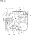
FIG. 5A is a side views illustrating an example of an operation of the stapler according to the present embodiment when the number of sheets to be bound by a staple is large or when the sheet is thick. -
FIG. 5B is a side view illustrating the example of the operation of the stapler according to the present embodiment when the number of sheets to be bound by a staple is large or when the sheet is thick. -
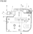
FIG. 5C is a side view illustrating the example of the operation of the stapler according to the present embodiment when the number of sheets to be bound by a staple is large or when the sheet is thick. - Hereinafter, an embodiment of a stapler according to the present disclosure will be described with reference to the drawings.
-
FIGS. 1A ,1B , and1C are side views illustrating an example of a stapler according to the present embodiment,FIGS. 1A and1B illustrate an internal configuration of astapler 1, andFIG. 1A illustrates an internal structure through alock plate 30 to be described later.FIG. 2 is a perspective view illustrating an example of the stapler according to the present embodiment. - The
stapler 1 includes amain body portion 2 andtable links 3 movably supported by themain body portion 2. Thestapler 1 further includes thelock plates 30 for moving thetable links 3 and clamp lock links 31 for moving thelock plates 30. - In the
stapler 1, acartridge 10 in which a staple (not illustrated) is accommodated is detachably attached to themain body portion 2. - The
main body portion 2 includes a drivingportion 4 that drives a staple (not illustrated) accommodated in thecartridge 10 into a sheet bundle P. Further, themain body portion 2 includes a first table 20 for sandwiching the sheet bundle P. The first table 20 is constituted by a portion facing one end portion of thetable link 3 in ahousing 21 of themain body portion 2. The first table 20 includes a part of thehousing 21 when the first table 20 is attached to themain body portion 2 and a part of thecartridge 10 exposed to thehousing 21, and a passage opening 20a through which a staple (not illustrated) driven into by the drivingportion 4 passes is exposed. The drivingportion 4 includes a driver (not illustrated) for driving a staple, a mechanism for driving the driver, and a passage through which the staple driven by the driver passes in thecartridge 10. - A
clinch portion 5 for bending leg portions of a staple (not illustrated) penetrating the sheet bundle P is attached to thetable link 3. A second table 32 for sandwiching the sheet bundle P is attached to thetable link 3. - The
clinch portion 5 and the second table 32 are attached to one end side of thetable link 3 at positions where theclinch portion 5 and the second table 32 face the drivingportion 4 and the first table 20. Theclinch portion 5 is attached at a position where theclinch portion 5 faces thepassage opening 20a. The other end side of thetable link 3 is rotatably supported on themain body portion 2 by ashaft 33. - The
table link 3 rotates about theshaft 33, thereby moving theclinch portion 5 and the second table 32 along a first direction in which theclinch portion 5 and the second table 32 are separated from and brought into contact with the drivingportion 4 and the first table 20 of themain body portion 2. Thetable link 3 is urged by an urgingmember 3a such as a coil spring in a direction in which theclinch portion 5 and the second table 32 approach the drivingportion 4 and the first table 20. - When the
table link 3 rotates about theshaft 33 in one direction, theclinch portion 5 and the second table 32 move in an arrow A1 direction toward the drivingportion 4 and the first table 20 of themain body portion 2. The arrow A1 direction is one of the first direction in which theclinch portion 5 and the second table 32 are separated from and brought into contact with the drivingportion 4 and the first table 20. When thetable link 3 rotates about theshaft 33 in the other direction opposite to the one direction, theclinch portion 5 and the second table 32 move in an arrow A2 direction opposite to the arrow A1 direction and away from the drivingportion 4 and the first table 20 of themain body portion 2. The arrow A2 direction is the other of the first direction in which theclinch portion 5 and the second table 32 are separated from and brought into contact with the drivingportion 4 and the first table 20. - The
lock plate 30 includes aregulation portion 30a that abuts against thetable link 3. Theregulation portion 30a moves along a second direction intersecting with the first direction toward and away from theclinch portion 5. Thelock plate 30 is supported by themain body portion 2 so as to be movable along the second direction indicated by arrows B1 and B2. - The
main body portion 2 includesframe abutting portions 22a that movably support thelock plates 30. Each of theframe abutting portions 22a is provided with an elongated hole-shaped opening extending along the second direction in aframe 22 constituting the exterior of themain body portion 2. - The
lock plate 30 includes slide guides 30b guided by theframe abutting portion 22a. Each of the slide guides 30b is an example of a guide portion, is constituted by an oval convex portion along the second direction, and protrudes laterally from thelock plate 30. In addition, the slide guides 30b are provided at a plurality of positions along the second direction, at two positions in the present embodiment. - The
lock plate 30 is supported by themain body portion 2 such that the slide guides 30b are guided by theframe abutting portion 22a by fitting the slide guides 30b into theframe abutting portion 22a, and thelock plate 30 is movable in the arrow B1 direction in which theregulation portion 30a moves away from theclinch portion 5 and the arrow B2 direction in which theregulation portion 30a approaches theclinch portion 5 in the direction opposite to the arrow B1 direction. The arrow B1 direction is one of the second direction intersecting the first direction in which theclinch portion 5 and the second table 32 are separated from and brought into contact with the drivingportion 4 and the first table 20. The arrow B2 direction is the other of the second direction intersecting the first direction. - Since the
lock plate 30 is provided with the slide guides 30b at two positions along the second direction, the slide guides 30b are supported by theframe abutting portion 22a at two front and rear positions along a moving direction of thelock plate 30. Accordingly, thelock plate 30 is prevented from rotating about the oneslide guide 30b or the like. - The
lock plate 30 is provided with theregulation portion 30a in the vicinity of a center between the two slide guides 30b. Accordingly, when a force is applied to theregulation portion 30a, the force is substantially equally applied to the two slide guides 30b, and thelock plate 30 is prevented from rotating about the oneslide guide 30b or the like. Further, wear of only oneslide guide 30b can be prevented. - The
table link 3 includes an abuttingportion 34 against which theregulation portion 30a abuts. The abuttingportion 34 is formed of a grooved cam that penetrates through the front and back of thetable link 3 and has a substantially V-shaped elongated hole in which theregulation portion 30a is inserted in a direction away from theclinch portion 5 from one end side toward the other end side of thetable link 3. In the present embodiment, the abuttingportion 34 is formed as an elongated hole inside thetable link 3, but an outer shape of thetable link 3 may be formed as the abuttingportion 34. - When the
table link 3 rotates about theshaft 33, the abuttingportion 34 is inclined with respect to the moving direction of thelock plate 30 according to a rotation angle of thetable link 3 with respect to themain body portion 2, and obliquely intersects with a movement path of theregulation portion 30a. - When the
regulation portion 30a of thetable link 3 is located at a standby position illustrated inFIG. 1A , theclinch portion 5 and the second table 32 are located at a standby position away from the drivingportion 4 and the first table 20. In a state where theregulation portion 30a is located at the standby position, theregulation portion 30a abuts against a surface of the abuttingportion 34 in the arrow A2 direction, and thetable link 3 is held at the standby position by the urging force of the urgingmember 3a without rotating theclinch portion 5 and the second table 32 in the direction of approaching the drivingportion 4 and the first table 20. - When the
lock plate 30 moves in the arrow B1 direction, theregulation portion 30a moves from the standby position to push the abuttingportion 34 of thetable link 3 and rotates thetable link 3 about theshaft 33 in cooperation with the urging force of the urgingmember 3a, thereby moving theclinch portion 5 and the second table 32 in the arrow A1 direction toward the drivingportion 4 and the first table 20. When thelock plate 30 moves in the arrow B2 direction, theregulation portion 30a moves theclinch portion 5 and the second table 32 in the arrow A2 direction away from theclinch portion 5 along the second direction intersecting the first direction in which theclinch portion 5 and the second table 32 are separated from and brought into contact with the drivingportion 4 and the first table 20. - Accordingly, the
regulation portion 30a moves along the second direction, thereby rotating thetable link 3 along the first direction in which theclinch portion 5 is separated from and brought into contact with the drivingportion 4. When theregulation portion 30a moves along the second direction, the position where theregulation portion 30a abuts against the abuttingportion 34 of thetable link 3 changes according to a distance between theclinch portion 5 and the drivingportion 4. Further, theregulation portion 30a regulates the movement of thetable link 3 in the first direction and regulates the movement of theclinch portion 5 in the arrow A2 direction away from the drivingportion 4 in a state where the position of theregulation portion 30a abutting against the abuttingportion 34 of thetable link 3 is changed according to the distance between theclinch portion 5 and the drivingportion 4 by moving in the second direction. - The
clamp lock link 31 is supported by themain body portion 2 so as to be rotatable about ashaft 31a located away from a center position of the component. Theclamp lock link 31 includes anengagement portion 3 1b at a position away from the center position of the component toward a side opposite to a side supported by theshaft 31a. Theengagement portion 31b protrudes from an outer periphery of theclamp lock link 31 in a direction opposite to the side supported by theshaft 31a. In theclamp lock link 31, theengagement portion 3 1b reciprocates in the arrow B1 direction and the arrow B2 direction by a rotation operation about theshaft 31a. Theclamp lock link 31 is urged by an urgingmember 31d such as a coil spring in a direction in which theengagement portion 3 1b moves in the arrow B1 direction. - The
lock plate 30 includes an engagedportion 30c that engages with theengagement portion 31b of theclamp lock link 31. The engagedportion 30c is formed by a recess having a shape with which theengagement portion 3 1b is engaged. -
FIG. 3A is a perspective view of the stapler illustrating an example of a drive unit,FIGS. 3B and 3C are perspective views of a main part illustrating the example of the drive unit, andFIG. 3D is a front view of a main part illustrating the example of the drive unit. - The
stapler 1 includes adrive unit 6 that drives thetable link 3, the drivingportion 4, theclinch portion 5, and the like. Thedrive unit 6 includes amotor 60 and adrive shaft 61 that is driven by themotor 60 to rotate. Thedrive shaft 61 includesclamp cams 62 that drive the table links 3,driver clinch cams 63 that drive the driver (not illustrated) of the drivingportion 4 in a staple driving direction and drive theclinch portion 5, adriver return cam 64 that drives the driver (not illustrated) of the drivingportion 4 in a direction opposite to the staple driving direction, and adrive gear 65 to which a drive force for rotating thedrive shaft 61 is transmitted. - Each of the
clamp cams 62 is made of sheet metal. Theclamp cam 62 is engaged with an engagement-convex portion 31c of theclamp lock link 31, and pushes the engagement-convex portion 31c by the rotation of thedrive shaft 61 to rotate theclamp lock link 31, thereby moving thelock plate 30 and driving thetable link 3 via thelock plate 30. - Each of the
driver clinch cams 63 is made of resin. Thedriver clinch cam 63 is integrally formed with a cam engaging with adriver link 40 connected to the driver (not illustrated) of the drivingportion 4 and a cam engaging with aclinch link 50 connected to theclinch portion 5. In addition, thedriver clinch cam 63 is integrally formed with asupport portion 63a of theclamp cam 62 and a bearingportion 63b. Thedriver clinch cam 63 is press-fitted to thedrive shaft 61. Theclamp cam 62 is press-fitted to thesupport portion 63a of thedriver clinch cam 63. This configuration prevents theclamp cam 62 and thedriver clinch cam 63 from rattling. - The
drive shaft 61 is provided with thedrive gear 65 in the vicinity of a center thereof in an extending direction, and thedriver return cam 64, thedriver clinch cam 63, and theclamp cam 62 are provided in this order from thedrive gear 65 on one side of thedrive shaft 61 across thedrive gear 65. Thedriver clinch cam 63 and theclamp cam 62 are provided in this order from thedrive gear 65 on the other side of thedrive shaft 61 across thedrive gear 65. - The
drive shaft 61 is supported by oneframe 22 via the bearingportion 63b of onedriver clinch cam 63 on one end side thereof in the extending direction. In addition, thedrive shaft 61 is supported by theother frame 22 via the bearingportion 63b of the otherdriver clinch cam 63 on the other end side thereof in the extending direction. Accordingly, thedrive shaft 61 is supported by theframes 22 on both sides thereof sandwiching thedrive gear 65. - The
drive unit 6 includes a firstintermediate gear 66 that meshes with thegear 60a of themotor 60, and a secondintermediate gear 67 that meshes with the firstintermediate gear 66 and thedrive gear 65. - The first
intermediate gear 66 is supported by thehousing 21 on both sides in an extending direction of a shaft (not illustrated). The secondintermediate gear 67 is supported by theframes 22 on both sides in an extending direction of ashaft 67a. - Accordingly, in a configuration in which each of the
drive gear 65, the firstintermediate gear 66, and the secondintermediate gear 67 is supported on both sides of the shaft, it is possible to prevent bending of the shaft due to application of a biased force to the shaft. Further, thedrive gear 65, the firstintermediate gear 66, and the secondintermediate gear 67 can be provided inside the left andright frames 22, respectively, and the size of thestapler 1 can be reduced compared to a configuration in which each gear is provided outside theframes 22. -
FIGS. 4A ,4B , and4C are side views illustrating an example of an operation of the stapler according to the present embodiment when the number of sheets to be bound by a staple is small or when the sheet is thin,FIGS. 4A and4B show an internal configuration of thestapler 1, andFIG. 4A shows the internal structure through thelock plate 30. In addition,FIGS. 5A ,5B , and5C are side views illustrating an example of an operation of the stapler according to the present embodiment when the number of sheets to be bound by a staple is large or when the sheet is thick,FIGS. 5A and5B show an internal configuration of thestapler 1, andFIG. 5A shows the internal structure through thelock plate 30. - Next, the example of the operation of the stapler according to the present embodiment will be described with reference to the drawings. In the
stapler 1, when themotor 60 rotates and theclamp cam 62 rotates, theclamp lock link 31 rotates in an arrow C1 direction about theshaft 31a in cooperation with the urgingmember 31d. When theclamp lock link 31 rotates in the arrow C1 direction, thelock plate 30 in which theengagement portion 31b of theclamp lock link 31 and the engagedportion 30c are engaged with each other moves in the arrow B1 direction. - When the
lock plate 30 moves in the arrow B1 direction, theregulation portion 30a moving integrally with thelock plate 30 pushes the abuttingportion 34 of thetable link 3. In thetable link 3, an inclined portion of the abuttingportion 34 is pushed by theregulation portion 30a moving in the arrow B1 direction when the abuttingportion 34 obliquely intersects the movement path of theregulation portion 30a. - In the
table link 3, when the abuttingportion 34 is pushed by theregulation portion 30a in the arrow B1 direction, theclinch portion 5 and the second table 32 rotate about theshaft 33 in cooperation with the urgingmember 3a in the arrow A1 direction approaching the drivingportion 4 and the first table 20. - When the
table link 3 rotates in the arrow A1 direction, the sheet bundle P is sandwiched between the first table 20 and the second table 32. - When the
lock plate 30 moves in the arrow B1 direction and thetable link 3 rotates in the arrow A1 direction, the position where theregulation portion 30a abuts against the abuttingportion 34 moves in the direction away from theclinch portion 5. That is, the distance from the position where theregulation portion 30a abuts against the abuttingportion 34 to theclinch portion 5 changes in accordance with the distance between theclinch portion 5 and the drivingportion 4. - In the
stapler 1, when the number of sheets to be bound by a staple is small or when the sheet is thin, the sheet bundle P sandwiched between the first table 20 and the second table 32 is thinner than when the number of sheets to be bound by a staple (not illustrated) is large or when the sheet is thick. - Accordingly, in the
stapler 1, when the number of sheets to be bound by a staple is small or when the sheet is thin, the distance between theclinch portion 5 and the drivingportion 4 is shorter than when the number of sheets to be bound by a staple is large or when the sheet is thick. - In the
stapler 1, as illustrated inFIGS. 4A ,4B , and4C , when the distance between theclinch portion 5 and the drivingportion 4 becomes shorter, a distance L1 from the position where theregulation portion 30a abuts the abuttingportion 34 to theclinch portion 5 is longer than a distance L2 when the distance between theclinch portion 5 and the drivingportion 4 is long, as illustrated inFIGS. 5A ,5B , and5C . - In the
stapler 1, after the sheet bundle P is sandwiched between the first table 20 and the second table 32, themotor 60 further rotates so that a staple (not illustrated) is driven into the sheet bundle P by an operation of the drivingportion 4. - In the
stapler 1, when the number of sheets to be bound by a staple is large, or when the sheet is thick, compared to when the number of sheets to be bound by a staple is small, or when the sheet is thin, a contact surface between the leg portion and the sheet bundle becomes large when the leg portion of the staple penetrates the sheet bundle P. - Accordingly, in the
stapler 1, when the number of sheets to be bound by a staple is large or when the sheet is thick, a force required to cause the leg portion of the staple to penetrate the sheet bundle P is increased during the operation of driving a staple into the sheet bundle P. - In the
table link 3, theregulation portion 30a abuts against the abuttingportion 34 between theclinch portion 5 and theshaft 33. Accordingly, when the distance from the position where theregulation portion 30a abuts against the abuttingportion 34 to theclinch portion 5 is short, a rigidity of thetable link 3 is higher than that when the distance is long. - As illustrated in
FIGS. 5A ,5B , and5C , when the number of sheets to be bound by a staple is large or when the sheet is thick, the distance L2 from the position where theregulation portion 30a abuts against the abuttingportion 34 to theclinch portion 5 is shorter than when the number of sheets to be bound by a staple is small or when the sheet is thin as illustrated inFIGS. 4A ,4B , and4C . - Accordingly, when the number of sheets to be bound by a staple is large or when the sheet is thick, it is possible to prevent the
table link 3 from being bent by the operation of driving the staple into the sheet bundle P by the drivingportion 4 and to drive a staple into the sheet bundle so that staple crown of the staple is not lifted from the sheet bundle. - In the
stapler 1, after a staple is driven into the sheet bundle, themotor 60 is further rotated to bend the leg portion of the staple (not illustrated) by the operation of theclinch portion 5. - In the
stapler 1, in the operation of bending the leg portion of the staple penetrating the sheet bundle P at the clinch portion, a force to rotate thetable link 3 in the arrow A2 direction is applied by a reaction force of a force with which theclinch portion 5 presses the leg portion. - In the
stapler 1, the operation of thetable link 3 that sandwiches the sheet bundle P and the operation of theclinch portion 5 that bends the leg portion of the staple are interlocked with each other, and the rotation of themotor 60 continues in a state where the sheet bundle P is sandwiched between the first table 20 and the second table 32. - When the operation of the
clinch portion 5 that bends the leg portion of the staple is performed in a state where theregulation portion 30a and the abuttingportion 34 abut against each other and the rotation of thetable link 3 in the arrow A2 direction is regulated, the force to rotate thetable link 3 in the arrow A2 direction is applied. The excess of an operation stroke of theclinch portion 5 is absorbed by deformation of thetable link 3. - In the
stapler 1, a load required for deforming thetable link 3 increases as the rigidity of thetable link 3 increases. At this time, a load applied to themotor 60 via thedrive unit 6 increases, and a value of a current flowing through themotor 60 increases. - As illustrated in
FIGS. 4A ,4B , and4C , when the number of sheets to be bound by a staple is small or when the sheet is thin, the distance L1 from the position where theregulation portion 30a abuts against the abuttingportion 34 to theclinch portion 5 is longer than the distance L2 when the number of sheets to be bound by a staple is large or when the sheet is thick as illustrated inFIGS. 5A ,5B , and5C . - When the distance from the position where the
regulation portion 30a abuts against the abuttingportion 34 to theclinch portion 5 is long, the rigidity of thetable link 3 is lower than that when the distance is short. When the rigidity of thetable link 3 decreases, thetable link 3 can be bent when the force to rotate thetable link 3 in the arrow A2 direction is applied. - Accordingly, when the number of sheets to be bound by a staple is small or when the sheet is thin, when the force to rotate the
table link 3 in the arrow A2 direction is applied at the time of the operation of bending the leg portion of the staple by theclinch portion 5, it is possible to bend thetable link 3, and to prevent an increase in the value of the current flowing through themotor 60.
Claims (9)
- A stapler comprising:a driving portion configured to drive a staple into a sheet bundle;a clinch portion configured to bend a leg portion of the staple driven into and penetrating the sheet bundle;a table link configured to support the clinch portion at a position facing the driving portion and move the clinch portion in a first direction in which the clinch portion separated from and brought into contact with the driving portion;a motor configured to drive the driving portion; anda regulation portion configured to move in a second direction intersecting the first direction while abutting against the table link and regulate a movement of the clinch portion in a direction away from the driving portion, whereina position where the regulation portion abuts against the table link changes in a direction toward the clinch portion as the clinch portion and the driving portion are separated from each other.
- The stapler according to claim 1, wherein
the position where the regulation portion abuts against the table link changes in a direction away from the clinch portion as the clinch portion and the driving portion approach each other. - The stapler according to claim 2, wherein
the table link has one end side to which the clinch portion is attached, the other end side which is rotatably supported by a shaft, and an abutting portion against which the regulation portion abuts between the clinch portion and the shaft. - The stapler according to claim 3, further comprising:a lock plate having the regulation portion; anda frame abutting portion configured to support the lock plate to be movable along the second direction, whereinthe lock plate has a guide portion that is guided by the frame abutting portion.
- The stapler according to claim 4, whereinthe lock plate includes a plurality of guide portions including the guide portion provided along the second direction, andthe regulation portion is provided between the plurality of guide portions.
- The stapler according to claim 4, wherein
the motor is configured to move the lock plate. - The stapler according to claim 3, wherein
the abutting portion is formed by a grooved cam extending in a direction away from the clinch portion. - The stapler according to claim 1, wherein
the abutting portion is a grooved cam that penetrates through a front and back of the table link, and shaped in an elongated hole extending in a direction away from the clinch portion. - The stapler according to claim 4, wherein
the frame abutting portion is an opening shaped in an elongated hole, and is configured to guide the convex guide portion to be movable horizontally.
Applications Claiming Priority (1)
| Application Number | Priority Date | Filing Date | Title |
|---|---|---|---|
| JP2022207979A JP2024092212A (en) | 2022-12-26 | 2022-12-26 | Stapler |
Publications (2)
| Publication Number | Publication Date |
|---|---|
| EP4393669A1 true EP4393669A1 (en) | 2024-07-03 |
| EP4393669B1 EP4393669B1 (en) | 2025-06-11 |
Family
ID=89321589
Family Applications (1)
| Application Number | Title | Priority Date | Filing Date |
|---|---|---|---|
| EP23219671.7A Active EP4393669B1 (en) | 2022-12-26 | 2023-12-22 | Stapler |
Country Status (4)
| Country | Link |
|---|---|
| US (1) | US12515369B2 (en) |
| EP (1) | EP4393669B1 (en) |
| JP (1) | JP2024092212A (en) |
| CN (1) | CN118254131A (en) |
Families Citing this family (1)
| Publication number | Priority date | Publication date | Assignee | Title |
|---|---|---|---|---|
| JP2026080494A (en) * | 2024-10-31 | 2026-05-18 | マックス株式会社 | stapler |
Citations (1)
| Publication number | Priority date | Publication date | Assignee | Title |
|---|---|---|---|---|
| JP2005059338A (en) | 2003-08-11 | 2005-03-10 | Max Co Ltd | Lock mechanism of paper pressing table in stapler |
Family Cites Families (2)
| Publication number | Priority date | Publication date | Assignee | Title |
|---|---|---|---|---|
| US5791543A (en) * | 1995-12-11 | 1998-08-11 | Max Co., Ltd. | Electric stapler |
| JP3620351B2 (en) * | 1999-07-06 | 2005-02-16 | マックス株式会社 | Electric stapler |
-
2022
- 2022-12-26 JP JP2022207979A patent/JP2024092212A/en active Pending
-
2023
- 2023-12-22 EP EP23219671.7A patent/EP4393669B1/en active Active
- 2023-12-22 CN CN202311776904.9A patent/CN118254131A/en active Pending
- 2023-12-26 US US18/396,454 patent/US12515369B2/en active Active
Patent Citations (2)
| Publication number | Priority date | Publication date | Assignee | Title |
|---|---|---|---|---|
| JP2005059338A (en) | 2003-08-11 | 2005-03-10 | Max Co Ltd | Lock mechanism of paper pressing table in stapler |
| EP1655109A1 (en) * | 2003-08-11 | 2006-05-10 | Max Co., Ltd. | Locking mechanism for stapler paper presser table |
Also Published As
| Publication number | Publication date |
|---|---|
| CN118254131A (en) | 2024-06-28 |
| EP4393669B1 (en) | 2025-06-11 |
| US12515369B2 (en) | 2026-01-06 |
| JP2024092212A (en) | 2024-07-08 |
| US20240208103A1 (en) | 2024-06-27 |
Similar Documents
| Publication | Publication Date | Title |
|---|---|---|
| US5460314A (en) | Stapler with improved stapling precision | |
| EP4393669B1 (en) | Stapler | |
| EP1711314B1 (en) | Stapler | |
| EP2246162B1 (en) | Stapler | |
| EP1470901B1 (en) | Stapler | |
| US6820787B2 (en) | Stapler | |
| US6902094B2 (en) | Stapler apparatus | |
| KR101018165B1 (en) | Table locking mechanism in electric stapler | |
| EP1655109B1 (en) | Locking mechanism for stapler paper presser table | |
| EP4484100B1 (en) | Stapler | |
| EP2338654A2 (en) | Stapler | |
| EP2127834B1 (en) | Clinch positioning mechansim of stapler | |
| JPH09327802A (en) | Stapling equipment | |
| US20050098603A1 (en) | Stapler cartridge and stapler apparatus comprising the same | |
| EP1795306A1 (en) | Stapler | |
| EP4393650A1 (en) | Stapler | |
| EP1749619B1 (en) | Clincher device for stapler | |
| US12491657B2 (en) | Stapler | |
| US7922060B2 (en) | Stapler | |
| US20030052151A1 (en) | Staple-former in a stapler | |
| US7661570B2 (en) | Stapler | |
| JP2005081526A (en) | Clincher device for stapler |
Legal Events
| Date | Code | Title | Description |
|---|---|---|---|
| PUAI | Public reference made under article 153(3) epc to a published international application that has entered the european phase |
Free format text: ORIGINAL CODE: 0009012 |
|
| STAA | Information on the status of an ep patent application or granted ep patent |
Free format text: STATUS: THE APPLICATION HAS BEEN PUBLISHED |
|
| AK | Designated contracting states |
Kind code of ref document: A1 Designated state(s): AL AT BE BG CH CY CZ DE DK EE ES FI FR GB GR HR HU IE IS IT LI LT LU LV MC ME MK MT NL NO PL PT RO RS SE SI SK SM TR |
|
| STAA | Information on the status of an ep patent application or granted ep patent |
Free format text: STATUS: REQUEST FOR EXAMINATION WAS MADE |
|
| 17P | Request for examination filed |
Effective date: 20240913 |
|
| RBV | Designated contracting states (corrected) |
Designated state(s): AL AT BE BG CH CY CZ DE DK EE ES FI FR GB GR HR HU IE IS IT LI LT LU LV MC ME MK MT NL NO PL PT RO RS SE SI SK SM TR |
|
| GRAP | Despatch of communication of intention to grant a patent |
Free format text: ORIGINAL CODE: EPIDOSNIGR1 |
|
| STAA | Information on the status of an ep patent application or granted ep patent |
Free format text: STATUS: GRANT OF PATENT IS INTENDED |
|
| INTG | Intention to grant announced |
Effective date: 20250117 |
|
| GRAS | Grant fee paid |
Free format text: ORIGINAL CODE: EPIDOSNIGR3 |
|
| GRAA | (expected) grant |
Free format text: ORIGINAL CODE: 0009210 |
|
| STAA | Information on the status of an ep patent application or granted ep patent |
Free format text: STATUS: THE PATENT HAS BEEN GRANTED |
|
| AK | Designated contracting states |
Kind code of ref document: B1 Designated state(s): AL AT BE BG CH CY CZ DE DK EE ES FI FR GB GR HR HU IE IS IT LI LT LU LV MC ME MK MT NL NO PL PT RO RS SE SI SK SM TR |
|
| REG | Reference to a national code |
Ref country code: GB Ref legal event code: FG4D |
|
| REG | Reference to a national code |
Ref country code: CH Ref legal event code: EP |
|
| REG | Reference to a national code |
Ref country code: IE Ref legal event code: FG4D |
|
| REG | Reference to a national code |
Ref country code: DE Ref legal event code: R096 Ref document number: 602023003973 Country of ref document: DE |
|
| PG25 | Lapsed in a contracting state [announced via postgrant information from national office to epo] |
Ref country code: ES Free format text: LAPSE BECAUSE OF FAILURE TO SUBMIT A TRANSLATION OF THE DESCRIPTION OR TO PAY THE FEE WITHIN THE PRESCRIBED TIME-LIMIT Effective date: 20250611 Ref country code: FI Free format text: LAPSE BECAUSE OF FAILURE TO SUBMIT A TRANSLATION OF THE DESCRIPTION OR TO PAY THE FEE WITHIN THE PRESCRIBED TIME-LIMIT Effective date: 20250611 |
|
| REG | Reference to a national code |
Ref country code: LT Ref legal event code: MG9D |
|
| PG25 | Lapsed in a contracting state [announced via postgrant information from national office to epo] |
Ref country code: GR Free format text: LAPSE BECAUSE OF FAILURE TO SUBMIT A TRANSLATION OF THE DESCRIPTION OR TO PAY THE FEE WITHIN THE PRESCRIBED TIME-LIMIT Effective date: 20250912 Ref country code: NO Free format text: LAPSE BECAUSE OF FAILURE TO SUBMIT A TRANSLATION OF THE DESCRIPTION OR TO PAY THE FEE WITHIN THE PRESCRIBED TIME-LIMIT Effective date: 20250911 |
|
| REG | Reference to a national code |
Ref country code: NL Ref legal event code: MP Effective date: 20250611 |
|
| PG25 | Lapsed in a contracting state [announced via postgrant information from national office to epo] |
Ref country code: BG Free format text: LAPSE BECAUSE OF FAILURE TO SUBMIT A TRANSLATION OF THE DESCRIPTION OR TO PAY THE FEE WITHIN THE PRESCRIBED TIME-LIMIT Effective date: 20250611 |
|
| PG25 | Lapsed in a contracting state [announced via postgrant information from national office to epo] |
Ref country code: HR Free format text: LAPSE BECAUSE OF FAILURE TO SUBMIT A TRANSLATION OF THE DESCRIPTION OR TO PAY THE FEE WITHIN THE PRESCRIBED TIME-LIMIT Effective date: 20250611 |
|
| PG25 | Lapsed in a contracting state [announced via postgrant information from national office to epo] |
Ref country code: RS Free format text: LAPSE BECAUSE OF FAILURE TO SUBMIT A TRANSLATION OF THE DESCRIPTION OR TO PAY THE FEE WITHIN THE PRESCRIBED TIME-LIMIT Effective date: 20250911 |
|
| PG25 | Lapsed in a contracting state [announced via postgrant information from national office to epo] |
Ref country code: LV Free format text: LAPSE BECAUSE OF FAILURE TO SUBMIT A TRANSLATION OF THE DESCRIPTION OR TO PAY THE FEE WITHIN THE PRESCRIBED TIME-LIMIT Effective date: 20250611 |
|
| PG25 | Lapsed in a contracting state [announced via postgrant information from national office to epo] |
Ref country code: NL Free format text: LAPSE BECAUSE OF FAILURE TO SUBMIT A TRANSLATION OF THE DESCRIPTION OR TO PAY THE FEE WITHIN THE PRESCRIBED TIME-LIMIT Effective date: 20250611 |
|
| PG25 | Lapsed in a contracting state [announced via postgrant information from national office to epo] |
Ref country code: PT Free format text: LAPSE BECAUSE OF FAILURE TO SUBMIT A TRANSLATION OF THE DESCRIPTION OR TO PAY THE FEE WITHIN THE PRESCRIBED TIME-LIMIT Effective date: 20251013 |
|
| REG | Reference to a national code |
Ref country code: AT Ref legal event code: MK05 Ref document number: 1802025 Country of ref document: AT Kind code of ref document: T Effective date: 20250611 |
|
| PG25 | Lapsed in a contracting state [announced via postgrant information from national office to epo] |
Ref country code: IS Free format text: LAPSE BECAUSE OF FAILURE TO SUBMIT A TRANSLATION OF THE DESCRIPTION OR TO PAY THE FEE WITHIN THE PRESCRIBED TIME-LIMIT Effective date: 20251011 |
|
| PGFP | Annual fee paid to national office [announced via postgrant information from national office to epo] |
Ref country code: DE Payment date: 20251028 Year of fee payment: 3 |
|
| PG25 | Lapsed in a contracting state [announced via postgrant information from national office to epo] |
Ref country code: SM Free format text: LAPSE BECAUSE OF FAILURE TO SUBMIT A TRANSLATION OF THE DESCRIPTION OR TO PAY THE FEE WITHIN THE PRESCRIBED TIME-LIMIT Effective date: 20250611 Ref country code: AT Free format text: LAPSE BECAUSE OF FAILURE TO SUBMIT A TRANSLATION OF THE DESCRIPTION OR TO PAY THE FEE WITHIN THE PRESCRIBED TIME-LIMIT Effective date: 20250611 |
|
| PG25 | Lapsed in a contracting state [announced via postgrant information from national office to epo] |
Ref country code: CZ Free format text: LAPSE BECAUSE OF FAILURE TO SUBMIT A TRANSLATION OF THE DESCRIPTION OR TO PAY THE FEE WITHIN THE PRESCRIBED TIME-LIMIT Effective date: 20250611 |
|
| PG25 | Lapsed in a contracting state [announced via postgrant information from national office to epo] |
Ref country code: PL Free format text: LAPSE BECAUSE OF FAILURE TO SUBMIT A TRANSLATION OF THE DESCRIPTION OR TO PAY THE FEE WITHIN THE PRESCRIBED TIME-LIMIT Effective date: 20250611 |
|
| PG25 | Lapsed in a contracting state [announced via postgrant information from national office to epo] |
Ref country code: EE Free format text: LAPSE BECAUSE OF FAILURE TO SUBMIT A TRANSLATION OF THE DESCRIPTION OR TO PAY THE FEE WITHIN THE PRESCRIBED TIME-LIMIT Effective date: 20250611 |
|
| PG25 | Lapsed in a contracting state [announced via postgrant information from national office to epo] |
Ref country code: SK Free format text: LAPSE BECAUSE OF FAILURE TO SUBMIT A TRANSLATION OF THE DESCRIPTION OR TO PAY THE FEE WITHIN THE PRESCRIBED TIME-LIMIT Effective date: 20250611 |
|
| PG25 | Lapsed in a contracting state [announced via postgrant information from national office to epo] |
Ref country code: RO Free format text: LAPSE BECAUSE OF FAILURE TO SUBMIT A TRANSLATION OF THE DESCRIPTION OR TO PAY THE FEE WITHIN THE PRESCRIBED TIME-LIMIT Effective date: 20250611 |
|
| REG | Reference to a national code |
Ref country code: DE Ref legal event code: R097 Ref document number: 602023003973 Country of ref document: DE |
|
| PG25 | Lapsed in a contracting state [announced via postgrant information from national office to epo] |
Ref country code: DK Free format text: LAPSE BECAUSE OF FAILURE TO SUBMIT A TRANSLATION OF THE DESCRIPTION OR TO PAY THE FEE WITHIN THE PRESCRIBED TIME-LIMIT Effective date: 20250611 |
|
| PG25 | Lapsed in a contracting state [announced via postgrant information from national office to epo] |
Ref country code: IT Free format text: LAPSE BECAUSE OF FAILURE TO SUBMIT A TRANSLATION OF THE DESCRIPTION OR TO PAY THE FEE WITHIN THE PRESCRIBED TIME-LIMIT Effective date: 20250611 |
|
| PLBE | No opposition filed within time limit |
Free format text: ORIGINAL CODE: 0009261 |
|
| STAA | Information on the status of an ep patent application or granted ep patent |
Free format text: STATUS: NO OPPOSITION FILED WITHIN TIME LIMIT |
|
| REG | Reference to a national code |
Ref country code: CH Ref legal event code: L10 Free format text: ST27 STATUS EVENT CODE: U-0-0-L10-L00 (AS PROVIDED BY THE NATIONAL OFFICE) Effective date: 20260423 |
|
| 26N | No opposition filed |
Effective date: 20260312 |
|
| PG25 | Lapsed in a contracting state [announced via postgrant information from national office to epo] |
Ref country code: LT Free format text: LAPSE BECAUSE OF FAILURE TO SUBMIT A TRANSLATION OF THE DESCRIPTION OR TO PAY THE FEE WITHIN THE PRESCRIBED TIME-LIMIT Effective date: 20250611 |
|
| PG25 | Lapsed in a contracting state [announced via postgrant information from national office to epo] |
Ref country code: MC Free format text: LAPSE BECAUSE OF FAILURE TO SUBMIT A TRANSLATION OF THE DESCRIPTION OR TO PAY THE FEE WITHIN THE PRESCRIBED TIME-LIMIT Effective date: 20250611 |
|
| PG25 | Lapsed in a contracting state [announced via postgrant information from national office to epo] |
Ref country code: SE Free format text: LAPSE BECAUSE OF FAILURE TO SUBMIT A TRANSLATION OF THE DESCRIPTION OR TO PAY THE FEE WITHIN THE PRESCRIBED TIME-LIMIT Effective date: 20250611 |