EP4393662A1 - Remote monitoring system, anomaly detection system, remote monitoring method, and program - Google Patents
Remote monitoring system, anomaly detection system, remote monitoring method, and program Download PDFInfo
- Publication number
- EP4393662A1 EP4393662A1 EP22861041.6A EP22861041A EP4393662A1 EP 4393662 A1 EP4393662 A1 EP 4393662A1 EP 22861041 A EP22861041 A EP 22861041A EP 4393662 A1 EP4393662 A1 EP 4393662A1
- Authority
- EP
- European Patent Office
- Prior art keywords
- state
- information
- monitored target
- sensing
- remote monitoring
- Prior art date
- Legal status (The legal status is an assumption and is not a legal conclusion. Google has not performed a legal analysis and makes no representation as to the accuracy of the status listed.)
- Granted
Links
Images






Classifications
-
- B—PERFORMING OPERATIONS; TRANSPORTING
- B25—HAND TOOLS; PORTABLE POWER-DRIVEN TOOLS; MANIPULATORS
- B25J—MANIPULATORS; CHAMBERS PROVIDED WITH MANIPULATION DEVICES
- B25J9/00—Program-controlled manipulators
- B25J9/16—Program controls
- B25J9/1674—Program controls characterised by safety, monitoring, diagnostic
-
- B—PERFORMING OPERATIONS; TRANSPORTING
- B25—HAND TOOLS; PORTABLE POWER-DRIVEN TOOLS; MANIPULATORS
- B25J—MANIPULATORS; CHAMBERS PROVIDED WITH MANIPULATION DEVICES
- B25J9/00—Program-controlled manipulators
- B25J9/16—Program controls
- B25J9/1628—Program controls characterised by the control loop
- B25J9/1653—Program controls characterised by the control loop parameters identification, estimation, stiffness, accuracy, error analysis
-
- G—PHYSICS
- G06—COMPUTING OR CALCULATING; COUNTING
- G06N—COMPUTING ARRANGEMENTS BASED ON SPECIFIC COMPUTATIONAL MODELS
- G06N20/00—Machine learning
-
- G—PHYSICS
- G06—COMPUTING OR CALCULATING; COUNTING
- G06V—IMAGE OR VIDEO RECOGNITION OR UNDERSTANDING
- G06V20/00—Scenes; Scene-specific elements
- G06V20/50—Context or environment of the image
- G06V20/52—Surveillance or monitoring of activities, e.g. for recognising suspicious objects
-
- H—ELECTRICITY
- H04—ELECTRIC COMMUNICATION TECHNIQUE
- H04Q—SELECTING
- H04Q9/00—Arrangements in telecontrol or telemetry systems for selectively calling a substation from a main station, in which substation desired apparatus is selected for applying a control signal thereto or for obtaining measured values therefrom
-
- G—PHYSICS
- G05—CONTROLLING; REGULATING
- G05B—CONTROL OR REGULATING SYSTEMS IN GENERAL; FUNCTIONAL ELEMENTS OF SUCH SYSTEMS; MONITORING OR TESTING ARRANGEMENTS FOR SUCH SYSTEMS OR ELEMENTS
- G05B2219/00—Program-control systems
- G05B2219/30—Nc systems
- G05B2219/40—Robotics, robotics mapping to robotics vision
- G05B2219/40607—Fixed camera to observe workspace, object, workpiece, global
-
- H—ELECTRICITY
- H04—ELECTRIC COMMUNICATION TECHNIQUE
- H04M—TELEPHONIC COMMUNICATION
- H04M11/00—Telephonic communication systems specially adapted for combination with other electrical systems
- H04M11/002—Telephonic communication systems specially adapted for combination with other electrical systems with telemetering systems
- H04M11/005—Telephonic communication systems specially adapted for combination with other electrical systems with telemetering systems using recorded signals, e.g. speech
Definitions
- a remote monitoring system is a remote monitoring system that detects an anomaly in a state of a monitored target that operates autonomously, and the remote monitoring system includes: a first obtainer that obtains state information from the monitored target, the state information indicating a state of the monitored target; a second obtainer that obtains first sensing information from a first sensing device, the first sensing device being provided outside the monitored target and performing sensing of the monitored target, the first sensing information indicating a result of the sensing of the monitored target; a state estimator that estimates a first state based on the first sensing information that the second obtainer obtains, the first state being the state of the monitored target; a state comparer that compares the state information that the first obtainer obtains with estimated state information that is based on the first state of the monitored target that the state estimator estimates; and a notifier that notifies a monitor of the remote monitoring system of an occurrence of an anomaly, based on a comparison result of the state comparer.
- the remote monitoring system can detect an anomaly in the monitored target with the use of the two items of sensing information, and thus the remote monitoring system can detect an anomaly more accurately than it does with the use of one item of sensing information.
- the remove monitoring system may further include an environment manager that manages environmental information linking an environment in which sensing of the monitored target is performed and an estimation accuracy of a state that the state estimator estimates, and a state determiner that determines one state from between the first state and the second state with use of the environmental information that the environment manager manages, and that outputs the one state determined as the estimated state information.
- an environment manager that manages environmental information linking an environment in which sensing of the monitored target is performed and an estimation accuracy of a state that the state estimator estimates
- a state determiner that determines one state from between the first state and the second state with use of the environmental information that the environment manager manages, and that outputs the one state determined as the estimated state information.
- the state determiner may select one of the first state or the second state with use of the environmental information, and output the one selected as the estimated state information.
- the state determiner may perform a weighting operation on the first state and the second state with use of the environmental information, and output a weighted state as the estimated state information.
- the first obtainer may obtain a current position of the monitored target as the state
- the state estimator may estimate the current position of the monitored target as the first state and the second state
- the environmental information may include an estimation accuracy of the first state and the second state with respect to time.
- the monitored target may be a robot
- the first sensing device may include a stationary camera
- the second sensing device may include a stationary microphone
- the remote monitoring system uses the stationary camera and the dust sensor as the sensing devices, and thus the remote monitoring system can effectively detect an anomaly in the position of the robot that performs a cleaning task.
- the environmental information that the environment manager manages can be served by information corresponding to the update of the state estimator. Accordingly, in the remote monitoring system, even when the state estimator is updated, a state can be, for example, selected by the state selector with the update taken into consideration. This feature contributes to the accurate detection of the fact that an attacker has altered the state of the monitored target.
- Remote monitoring system 101 is an information processing system for detecting an anomaly in the state of monitored target 102 that is located remotely and that operates autonomously.
- Remote monitoring system 101 is connected to monitored target 102 and each of external information sources 103a and 103b via network 104.
- Remote monitoring system 101 includes anomaly detection system 200 that, with the use of information that anomaly detection system 200 has obtained from each of external information sources 103a and 103b that have performed sensing of monitored target 102, detects an anomaly in the state of monitored target 102 sent from this monitored target 102.
- such information obtained from each of external information sources 103a and 103b is also referred to as sensing information or information for estimation.
- Monitored target 102 is a robot that operates autonomously, and non-limiting examples of monitored target 102 include a security robot, a delivery robot, and a cleaning robot.
- Monitored target 102 includes a camera, a microphone, and a sensor, such as an infrared sensor or an ultrasonic wave sensor, that detects the state of monitored target 102 (e.g., its position information).
- Monitored target 102 transmits the state of monitored target 102 (state information indicating the state of monitored target 102), such as the video information captured by the camera, the audio information collected by the microphone, or the position information estimated with the use of the sensor, to remote monitoring system 101 via network 104.
- State obtainer 201 receives state information that is transmitted from monitored target 102 and that indicates a state of this monitored target 102. According to the present embodiment, state obtainer 201 obtains the current position of monitored target 102 as a state of this monitored target 102. State obtainer 201 includes, for example, a communication module (a communication circuit). State obtainer 201 is one example of a first obtainer.
- FIG. 3 is a block diagram showing a functional configuration of state estimator training system 300 according to the present embodiment.
- FIG. 3 shows a configuration for performing a process of training one state estimator 303. It is to be noted that, although FIG. 3 shows external information source 103 for the sake of convenience, state estimator training system 300 obtains sensing information from each of external information sources 103a and 103b.
- State obtainer 201a has a configuration the same as the configuration of state obtainer 201 of anomaly detection system 200. State obtainer 201a obtains state information from monitored target 102. Meanwhile, information obtainer 202c has a configuration the same as the configuration of information obtainers 202a and 202b of anomaly detection system 200. Information obtainer 202c obtains sensing information from external information source 103.
- state estimator 303 trains the machine learning model so as to minimize the sum of squared error.
- the sum of squared error is one example of the estimation accuracy.
- State estimator 303 estimates the state of monitored target 102 based on an intrinsic parameter, such as a weight or a bias of a regression model, and the information of external information source 103 obtained from information obtainer 202c and outputs the estimated state and the time at which state estimator 303 has estimated the state of monitored target 102 to state trainer 301.
- an intrinsic parameter such as a weight or a bias of a regression model
- state trainer 301 may calculate information (e.g., the sum of squared error) indicating the estimation accuracy of at least one of the first state or the second state of monitored target 102 that state estimator training system 300 has estimated, based on the state of monitored target 102 that state obtainer 201 has obtained and the at least one of the first state or the second state of monitored target 102 that state estimator training system 300 has estimated. Then, state trainer 301 may output the information indicating the calculated estimation accuracy to state estimators 203a and 203b and environment manager 204.
- information e.g., the sum of squared error
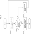
- FIG. 4 is a flowchart showing a training process (a remote monitoring method) in state estimator training system 300 according to the present embodiment.
- state estimator training system 300 (S401).
- state estimator 303 estimates the state of monitored target 102 with the use of the state that information obtainer 202c has extracted and outputs the estimated state to state trainer 301.
- State trainer 301 compares the state that state estimator 303 has estimated and the state of monitored target 102 that state obtainer 201 has extracted, calculates the estimation accuracy, and outputs the calculated estimation accuracy to state estimator 303.
- State estimator 303 performs a process of adjusting the intrinsic parameter so as to improve the estimation accuracy based on the estimation accuracy that state trainer 301 has calculated. These processes are repeated a predetermined number of times at step S401.
- State estimator training system 300 determines whether the estimation accuracy is sufficient (S402). State estimator training system 300 determines whether the estimation accuracy that environment manager 302 holds exceeds the accuracy set in advance.
- state estimator training system 300 If state estimator training system 300 has determined that the estimation accuracy is sufficient (YES at S402), state estimator training system 300 replaces the intrinsic parameter trained in state estimator 303 and the trained environmental information that environment manager 302 manages with, respectively, the intrinsic parameters of state estimators 203a and 203b of anomaly detection system 200 and the environmental information of environment manager 204, and the model is used then in anomaly detection system 200 (S403).
- state estimator training system 300 determines that the estimation accuracy is not sufficient (NO at S402), state estimator training system 300 determines that the improvement in the estimation accuracy of state estimator 303 is not likely and revises the training method (S404), and then state estimator training system 300 executes step S401 again.
- state trainer 301 in the revised training method, revises a mathematical model by, for example, changing the regression model from the linear regression to the regression tree and improves the estimation accuracy until the error falls within a permissible range.
- monitoring system 100 (or remote monitoring system 101) is provided with a training mode in which the machine learning model is trained. Furthermore, the training mode is executed, for example, within a space in which monitored target 102 is used.
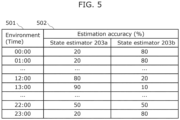
- FIG. 5 is a diagram showing one example of an environmental information table that environment manager 204 according to the present embodiment manages.
- an environmental information table includes environment 501 and estimation accuracy 502.
- Estimation accuracy 502 includes the estimation accuracy of state estimator 203a and the estimation accuracy of state estimator 203b.
- Environment 501 indicates the environment in which state estimators 203a and 203b have each estimated the state.
- environment 501 is the time, and estimation accuracy 502 with respect to time is shown.
- Estimation accuracy 502 indicates the estimation accuracy in environment 501.
- Estimation accuracy 502 indicates, in percentage, the ratio between the estimation accuracy of state estimator 203a and the estimation accuracy of state estimator 203b.
- the estimation accuracy is indicated by the ratio in order to show the difference in accuracy between state estimators 203a and 203b in a readily perceivable manner.
- the estimation accuracy may be shown with the use of any units that allow the difference in accuracy between state estimators 203a and 203b to be compared.
- the estimation accuracy is not limited to being indicated by numerical values and may be indicated by levels, such as "high", “mid”, and "low”.
- the estimation accuracy of the state of monitored target 102 that state estimator 203a has estimated at 12:00 based on the sensing information of external information source 103a is 80%
- the estimation accuracy of the state of monitored target 102 that state estimator 203b has estimated at 12:00 based on the sensing information of external information source 103b is 20%.
- the estimation accuracy of the state of monitored target 102 that state estimator 203a has estimated is higher than the estimation accuracy of the state of monitored target 102 that state estimator 203b has estimated.
- An environmental information table may be prepared in advance, may be created through training in state estimator training system 300, or may be created based on the environmental information of environment manager 302 of state estimator training system 300.
- an environmental information table is to be created through the training in state estimator training system 300, the environment held when an estimation is made is recorded in environment 501, and the estimation accuracy observed in that instance of estimation is recorded in estimation accuracy 502.
- FIG. 6A is a flowchart showing a process (a remote monitoring method) performed by remote monitoring system 101 according to the present embodiment.
- state obtainer 201 obtains, from monitored target 102, state information indicating the state of this monitored target 102 (S601).
- the state information includes time information that indicates the time at which, for example, a sensor in monitored target 102 has performed sensing.
- state estimators 203a and 203b each estimate the state of monitored target 102 based on each of the two or more items of information for estimation (S603). Specifically, state estimator 203a obtains, as the estimation result, the state of monitored target 102 (the first state) served by the output obtained when the first sensing information is input to the machine learning model. Meanwhile, state estimator 203b obtains, as the estimation result, the state of monitored target 102 (the second state) served by the output obtained when the second sensing information is input to the machine learning model.
- the first state and the second state as used herein are each information indicating the current position (e.g., the current position coordinates) of monitored target 102.
- State estimators 203a and 203b output the estimation results to state selector 205.
- state selector 205 determines one state of monitored target 102 from among two or more estimated states of monitored target 102 (S604). According to the present embodiment, state selector 205 selects either one of the first state and the second state that has a higher estimation accuracy based on the environmental information and determines the selected state as the estimated state of monitored target 102. State selector 205 obtains, from the environmental information table, the estimation accuracy of each of state estimators 203a and 203b held at the time indicated by the time information included in the state information, and based on the obtained estimation accuracy, state selector 205 selects the one with a higher estimation accuracy from the first state and the second state.
- State selector 205 outputs the selected estimated state of monitored target 102 to state comparer 207.
- state comparer 207 determines whether the difference between the state that state obtainer 201 has obtained from monitored target 102 and the estimated state is smaller than or equal to a threshold (S605).
- the threshold is set in advance.
- state comparer 207 determines that the difference is smaller than or equal to the threshold (YES at S605), this means that the state obtained from monitored target 102 is within a normal range, and thus state comparer 207 terminates the process. That the determination of YES is made at step S605 means that the state of monitored target 102 is not altered in monitored target 102. Meanwhile, if state comparer 207 determines that the difference is neither smaller than nor equal to the threshold (NO at S605), state comparer 207 outputs, to alert issuer 206, information indicating that an anomaly has been detected. That the determination of NO is made at step S605 means that the state of monitored target 102 has been altered in monitored target 102 or that it is highly likely that such an alteration has been made.
- FIG. 6B is a flowchart showing a process (a remote monitoring method) performed by state selector 205 according to the present embodiment.
- FIG. 6B is a flowchart showing the details of step S604 of FIG. 6A .
- state selector 205 obtains the states that state estimators 203a and 203b have estimated at 12:00 (S611).
- state selector 205 may weight each estimated state based on its estimation accuracy and calculate a newly estimated state in accordance with the weight. For example, a newly estimated state may be calculated such that a higher weight is given to a higher estimation accuracy.
- FIG. 7 is a block diagram showing a functional configuration of anomaly detection system 700 according to the present embodiment.
- a monitored target that anomaly detection system 700 monitors is robot 701, and external information sources are stationary camera 710 and stationary microphone 720.
- Robot 701 transmits its position information to anomaly detection system 700.
- information that can be used as the position information include the measured position information of a global positioning system (GPS) device provided in robot 701 or the position information estimated by the simultaneous localization and mapping (SLAM) provided in robot 701.
- GPS global positioning system
- SLAM simultaneous localization and mapping
- State obtainer 702 receives position information from robot 701. State obtainer 702 obtains the position information of robot 701 as the state of robot 701.
- Information obtainer 711 receives video 713 that stationary camera 710 has transmitted and extracts video data to be used to estimate a state. Examples of such video data include a bitmap image converted to grayscale. Video 713 is one example of first sensing information.
- Information obtainer 721 receives audio 723 that stationary microphone 720 has transmitted and extracts audio data to be used to estimate a state.
- audio data include pulse code modulation (PCM) data divided into predetermined cycles and subjected to a band pass filtering process so that only the frequency that allows for easy recognition of activity sound of robot 701 is included, but this is not a limiting example.
- Audio 723 is one example of second sensing information.
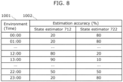
- Environment manager 704 manages environmental information 705 (see FIG. 8 ) that holds the estimation accuracy of stationary camera 710 with respect to time and the estimation accuracy of stationary microphone 720 with respect to time.
- State selector 703 selects, from between estimated state 714 and estimated state 724, the estimated state with a higher estimation accuracy, in accordance with environmental information 705 managed by environment manager 704.
- Alert issuer 206 has a configuration the same as the configuration of alert issuer 206 of anomaly detection system 200.
- State comparer 207 compares the position information that state obtainer 702 has extracted and the estimated state (the estimated position information) that state selector 703 has selected. If there is a difference of a predetermined magnitude or more between the aforementioned position information and the aforementioned estimated state, state comparer 207 determines that there is an anomaly and informs alert issuer 206 of the detected anomaly.
- state comparer 207 obtains, from state obtainer 702, the position information of robot 701 in the latitude and longitude format and obtains, from state selector 703, the estimated position information of robot 701 in the latitude and longitude format. State comparer 207 then calculates the distance between the two items of position information, and if the calculated distance exceeds a threshold set in advance, state comparer 207 determines that there is an anomaly.
- the illuminance within the facility is expected to be high and the noise surrounding robot 701 is expected to be large during the time range in which robot 701 works, while the illuminance within the facility is expected to be low and the noise surrounding robot 701 is expected to be small outside the time range in which robot 701 works.
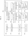
- FIG. 9 is a block diagram showing a functional configuration of anomaly detection system 800 according to the present embodiment.
- Stationary camera 810 is installed at a position where stationary camera 810 can easily capture an image of security robot 801, such as at a position near the ceiling of a room, and transmits captured video 813 to anomaly detection system 800.
- Illuminance sensor 820 is installed on a moving path of security robot 801 and transmits obtained illuminance value 823 to anomaly detection system 800.
- Stationary camera 810 is one example of a first sensing device, and illuminance sensor 820 is one example of a second sensing device.
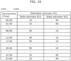
- State selector 803 selects, as the position of security robot 801, the position with a higher estimation accuracy under estimation accuracy 1102 at a predetermined time under environment 1101 in the environmental information table, and thus state selector 803 can select an optimal estimated state corresponding to any change in time.
- a monitored target that anomaly detection system 900 monitors is cleaning robot 901, and external information sources are stationary camera 910 and dust sensor 920.
- Information obtainer 911 receives video 913 that stationary camera 910 has transmitted and extracts video data to be used to estimate a state. Examples of such video data include a bitmap image converted to grayscale. Video 913 is one example of first sensing information.
- State estimator 912 estimates the position of cleaning robot 901 with the use of the video data that information obtainer 911 has extracted and outputs the estimated position as estimated state 914.
- cleaning robot 901 performs a cleaning task while people who engage in activities in its surroundings are not present, such as during the nighttime.
- the cleaning task that cleaning robot 901 performs causes dust to rise in its surroundings.
- information obtainer 921 obtains the sensor value from dust sensor 920, and based on the obtained sensor value, state estimator 922 estimates how far away cleaning robot 901 is located.
- Environment manager 904 manages environmental information 905 (see FIG. 12 ) that holds the estimation accuracy of stationary camera 910 with respect to time and the estimation accuracy of dust sensor 920 with respect to time.
- Alert issuer 206 has a configuration the same as the configuration of alert issuer 206 of anomaly detection system 200.
- State comparer 207 compares the position information that state obtainer 902 has extracted and the estimated state (the estimated position information) that state selector 903 has selected. If there is a difference of a predetermined magnitude or more between the aforementioned position information and the aforementioned estimated state, state comparer 207 determines that there is an anomaly and informs alert issuer 206 of the detected anomaly.
- FIG. 12 is a diagram showing one example of an environmental information table that environment manager 904 of anomaly detection system 900 according to the present embodiment manages.
- the estimation accuracy of state estimator 912 is set high during the time range from 07:00 to 21:00, which is the time range in which the surroundings of cleaning robot 901 is bright as in the daytime and an image of cleaning robot 901 is captured clearly in the video of stationary camera 910, and the estimation accuracy of state estimator 922 is set high during the time range from 21:00 to 07:00, which is the time range in which an image of cleaning robot 901 is not captured clearly in the vide of stationary camera 910 since the surroundings of cleaning robot 901 is dark as in the nighttime.
- State selector 903 selects, as the position of cleaning robot 901, the position with a higher estimation accuracy under estimation accuracy 1202 at a predetermined time under environment 1201 in the environmental information table, and thus state selector 903 can select an optimal estimated state corresponding to any change in time.
- the environmental information table may be created from the environmental information in environment manager 302 of state estimator training system 300 after state estimators 912 and 922 have been trained in state estimator training system 300.
- a monitored target according to each of the foregoing embodiments may be a mobile body used indoors or a mobile body used outdoors.
- the monitoring system may include only one external information source.
- an anomaly detection system does not need to include a state selector.
- an environment manager may output environmental information to a state comparer, and a state comparer may compare state information and estimated state information based on environmental information.
- a state comparer may, for example, change the threshold against which the difference between state information and estimated state information is compared, in accordance with environmental information. For example, a state comparer may change the threshold to a higher value as the estimation accuracy indicated by environmental information is higher.
- a stationary camera is used as a first sensing device, but this is not a limiting example.
- a first sensing device and a second sensing device may be any device that can obtain different sensing information, and a sensing device other than a stationary camera, for example, may also be used.
- the constituent elements may each be implemented by a dedicated piece of hardware or may each be implemented through the execution of a software program suitable for a corresponding constituent element.
- the constituent elements may each be implemented as a program executing unit, such as a CPU or a processor, reads out a software program recorded on a recording medium, such as a hard disk or a semiconductor memory, and executes the software program.
- a plurality of functional blocks may be implemented as a single functional block, a single functional block may be divided into a plurality of functional blocks, or one or more of the functions may be transferred to another functional block.
- the functions of a plurality of functional blocks having similar functions may be processed in parallel or through time division by a single piece of hardware or software.
- the remote monitoring system may be implemented in the form of a single device or in the form of a plurality of devices.
- the constituent elements of the remote monitoring system may be distributed over the plurality of devices in any manner.
- there is no particular limitation on the method of communication between the plurality of devices and such communication may be wireless communication or wired communication.
- the devices may also communicate with each other through a combination of wireless communication and wired communication.
- each constituent element described according to the foregoing embodiments and so forth may be implement by software or may typically be implemented in the form of an LSI circuit, which is an integrated circuit.
- the constituent elements may each be implemented by a single chip, or a part or the whole of the constituent elements may be implemented by a single chip.
- an LSI circuit is illustrated as an example in the above, depending on the difference in the degree of integration, such a circuit may also be called an IC, a system LSI circuit, a super LSI circuit, or an ultra LSI circuit.
- the techniques for circuit integration are not limited to LSI, and an integrated circuit may be implemented by a dedicated circuit (e.g., a general purpose circuit that executes a dedicated program) or by a general purpose processor.
- a field programmable gate array that can be programmed after an LSI circuit has been manufactured or a reconfigurable processor in which the connections or the settings of the circuit cells within an LSI circuit can be reconfigured may also be used.
- FPGA field programmable gate array
- the constituent elements may be integrated with the use of such different techniques.
- a system LSI circuit is an ultra-multifunctional LSI circuit manufactured by integrating a plurality of processors on a single chip, and is, specifically, a computer system that includes, for example, a microprocessor, a read only memory (ROM), or a random access memory (RAM).
- the ROM stores a computer program.
- the microprocessor operates in accordance with the computer program, and thus the system LSI circuit implements its functions.
- one aspect of the present disclosure may be a computer program that causes a computer to execute each of the characteristic steps included in the remote monitoring method indicated in any of FIG. 4 , FIG. 6A , and FIG. 6B .
- such a program may be a program to be executed by a computer.
- One aspect of the present disclosure may be a non-transitory computer readable recording medium having such a program recorded thereon.
- such a program may be recorded on a recording medium, which then may be distributed.
- a distributed program can be installed onto a device including another processor, and the program can be executed by this processor.
- the device can perform each of the processes described above.
- a remote monitoring system that detects an anomaly in a state of a monitored target that operates autonomously, the remote monitoring system comprising:
- the remote monitoring system according to technique 2 further comprising:
- the remote monitoring system wherein the state determiner selects one of the first state or the second state with use of the environmental information, and outputs the one selected as the estimated state information.
- the remote monitoring system wherein the state determiner performs a weighting operation on the first state and the second state with use of the environmental information, and outputs a weighted state as the estimated state information.
- the remote monitoring system according to any one of techniques 3 to 9, further comprising: a state trainer that calculates information indicating an estimation accuracy of at least one of the first state or the second state based on the state of the monitored target that the first obtainer obtains and the at least one of the first state or the second state of the monitored target that the state estimator estimates, and that outputs the information calculated indicating the estimation accuracy to the state estimator and the environment manager.
- a state trainer that calculates information indicating an estimation accuracy of at least one of the first state or the second state based on the state of the monitored target that the first obtainer obtains and the at least one of the first state or the second state of the monitored target that the state estimator estimates, and that outputs the information calculated indicating the estimation accuracy to the state estimator and the environment manager.
- the remote monitoring system according to technique 10, wherein the environment manager determines an estimation accuracy of the state that the state estimator estimates, based on the information that is obtained from the state trainer and indicates the estimation accuracy.
- the remote monitoring system according to technique 10 or 11, wherein the state trainer outputs the information calculated indicating the estimation accuracy to the state estimator and the environment manager before the monitored target is put into operation.
- the remote monitoring system according to any one of techniques 10 to 12, wherein the state trainer outputs the information calculated indicating the estimation accuracy to the state estimator and the environment manager while the monitored target is in operation.
- An anomaly detection system that detects an anomaly in a state of a monitored target that operates autonomously, the anomaly detection system comprising:
- a remote monitoring method of detecting an anomaly in a state of a monitored target that operates autonomously comprising:
- the present disclosure finds its effective use in an anomaly detection system that, when remotely monitoring a robot that operates autonomously, determines whether the state that the robot being monitored sends to a remote monitoring system differs from the actual state.
Landscapes
- Engineering & Computer Science (AREA)
- Robotics (AREA)
- Mechanical Engineering (AREA)
- Theoretical Computer Science (AREA)
- Physics & Mathematics (AREA)
- General Physics & Mathematics (AREA)
- Software Systems (AREA)
- Artificial Intelligence (AREA)
- Computer Networks & Wireless Communication (AREA)
- Computer Vision & Pattern Recognition (AREA)
- Data Mining & Analysis (AREA)
- Evolutionary Computation (AREA)
- Medical Informatics (AREA)
- Multimedia (AREA)
- Computing Systems (AREA)
- General Engineering & Computer Science (AREA)
- Mathematical Physics (AREA)
- Alarm Systems (AREA)
Abstract
Description
- The present disclosure relates to a remote monitoring system, an anomaly detection system, a remote monitoring method, and a program.
- Advancements in artificial intelligence (AI) and communication technologies in recent years have enabled robots to autonomously carry out more sophisticated activities. Thus, there is an expectation that robots will fill the labor shortage that may arise in the near future due to a decrease in the workforce.
- To operate such robots efficiently, centralized management through remote control or remote monitoring is indispensable. However, if such centralized management has a vulnerability, a robot can be controlled maliciously by an attacker. In one conceivable case, an attacker who has intruded into a robot may alter its state to be sent to a remote monitoring system and may conceal such an alteration, so that a person who monitors the robot fails to notice the anomaly.
- To detect such an anomaly in, for example, an in-vehicle network, an anomaly detecting method has been contemplated that detects an alteration by comparing the travel state in the network and the travel state estimated based on the peripheral information obtained by, for example, an onboard camera (see, for example, Patent Literature (PTL) 1).
- [PTL 1]
International Patent Publication No.WO2019/216306 - With the technique disclosed in PTL 1, however, if the attacker has altered the peripheral information as well, the fact that the attacker has altered the state of the monitored target, or the robot, cannot be detected.
- Accordingly, the present disclosure provides a remote monitoring system, an anomaly detection system, a remote monitoring method, and a program that, even if an attacker has altered peripheral information, can detect the fact that the attacker has altered a state of a monitored target.
- A remote monitoring system according to one aspect of the present disclosure is a remote monitoring system that detects an anomaly in a state of a monitored target that operates autonomously, and the remote monitoring system includes: a first obtainer that obtains state information from the monitored target, the state information indicating a state of the monitored target; a second obtainer that obtains first sensing information from a first sensing device, the first sensing device being provided outside the monitored target and performing sensing of the monitored target, the first sensing information indicating a result of the sensing of the monitored target; a state estimator that estimates a first state based on the first sensing information that the second obtainer obtains, the first state being the state of the monitored target; a state comparer that compares the state information that the first obtainer obtains with estimated state information that is based on the first state of the monitored target that the state estimator estimates; and a notifier that notifies a monitor of the remote monitoring system of an occurrence of an anomaly, based on a comparison result of the state comparer.
- An anomaly detection system according to one aspect of the present disclosure is an anomaly detection system that detects an anomaly in a state of a monitored target that operates autonomously, and the anomaly detection system includes: a first obtainer that obtains state information from the monitored target, the state information indicating a state of the monitored target; a second obtainer that obtains sensing information from a sensing device, the sensing device being provided outside the monitored target and performing sensing of the monitored target, the sensing information indicating a result of the sensing of the monitored target; a state estimator that estimates the state of the monitored target based on the sensing information that the second obtainer obtains; and a state comparer that compares the state information that the first obtainer obtains with estimated state information that is based on the state of the monitored target that the state estimator estimates.
- A remote monitoring method according to one aspect of the present disclosure is a remote monitoring method of detecting an anomaly in a state of a monitored target that operates autonomously, and the remote monitoring method includes: obtaining state information from the monitored target, the state information indicating a state of the monitored target; obtaining sensing information from a sensing device, the sensing device being provided outside the monitored target and performing sensing of the monitored target, the sensing information indicating a result of the sensing of the monitored target; estimating the state of the monitored target based on the sensing information obtained; comparing the state information obtained with estimated state information that is based on the state estimated of the monitored target; and notifying a monitor of a remote monitoring system of an occurrence of an anomaly, based on a comparison result of the state information and the estimated state information.
- A program according to one aspect of the present disclosure is a program for causing a computer to execute the remote monitoring method above.
- With the remote monitoring system and so forth according to some aspects of the present disclosure, even if an attacker has altered peripheral information, the fact that the attacker has altered a state of a monitored target can be detected.
-
- [
FIG. 1 ]
FIG. 1 is a diagram showing a configuration of a monitoring system according to Embodiment 1. - [
FIG. 2 ]
FIG. 2 is a block diagram showing a functional configuration of an anomaly detection system according to Embodiment 1. - [
FIG. 3 ]
FIG. 3 is a block diagram showing a functional configuration of a state estimator training system according to Embodiment 1. - [
FIG. 4 ]
FIG. 4 is a flowchart showing a training process in the state estimator training system according to Embodiment 1. - [
FIG. 5 ]
FIG. 5 is a diagram showing one example of an environmental information table that an environment manager of the state estimator training system according to Embodiment 1 manages. - [
FIG. 6A ]
FIG. 6A is a flowchart showing a process performed by a remote monitoring system according to Embodiment 1. - [
FIG. 6B ]
FIG. 6B is a flowchart showing a process performed by a state selector according to Embodiment 1. - [
FIG. 7 ]
FIG. 7 is a block diagram showing a functional configuration of an anomaly detection system according to Embodiment 2. - [
FIG. 8 ]
FIG. 8 is a diagram showing one example of an environmental information table that an environment manager of the anomaly detection system according to Embodiment 2 manages. - [
FIG. 9 ]
FIG. 9 is a block diagram showing a functional configuration of an anomaly detection system according to Embodiment 3. - [
FIG. 10 ]
FIG. 10 is a diagram showing one example of an environmental information table that an environment manager of the anomaly detection system according to Embodiment 3 manages. - [
FIG. 11 ]
FIG. 11 is a block diagram showing a functional configuration of an anomaly detection system according to Embodiment 4. - [
FIG. 12 ]
FIG. 12 is a diagram showing one example of an environmental information table that an environment manager of the anomaly detection system according to Embodiment 4 manages. - Conventional robots that operate autonomously, such as cleaning robots, are mainly those which carry out limited operations within a limited space. Robots, such as security robots or delivery robots, that have appeared in recent years, however, carry out more sophisticated operations (e.g., more sophisticated tasks) in a larger space.
- With the expansion of activity ranges of robots arises the need to monitor a large number of robots that are scattered over various locations, and thus functions for remotely and centrally controlling and monitoring robots are becoming more important.
- Meanwhile, for the purpose of controlling and monitoring a robot remotely, the robot may be provided with a function for connecting to a communication network, and that function may allow an attacker to access the robot remotely. This leads to a concern that, if the robot is controlled maliciously, damage may be caused, for example, by a leak of information from within a facility or by a malicious operation on equipment within a facility.
- A measure contemplated to prevent such damage is for a remote monitoring system to monitor a robot by communicating with the robot to find any anomaly in the state of the robot. However, if an attacker has altered the peripheral information in addition to the state of the robot to be sent to the remote monitoring system, the remote monitoring system cannot detect the fact that the state of that robot has been altered. Herein, the state of a robot is, for example, the position of the robot, but this is not a limiting example.
- Accordingly, the inventors of the present application have diligently looked into remote monitoring systems and so forth that, even if an attacker has altered the peripheral information, can detect the fact that the attacker has altered a state of a monitored target, or a robot, and have devised a remote monitoring system and so forth described hereinafter. For example, according to the present disclosure, information obtained by sensing a monitored target is obtained from an outside information source (an external information source) that is independent from the monitored target, and the state of the monitored target estimated based on the obtained information is compared with a state obtained from the monitored target, such as a robot. Thus, an alteration made to the state of the monitored target by an attacker is detected, and an alert is issued to a monitor. With this configuration, the monitor that has received the alert can promptly take necessary measures to limit any damage to minimum.
- A remote monitoring system according to one aspect of the present disclosure is a remote monitoring system that detects an anomaly in a state of a monitored target that operates autonomously, and the remote monitoring system includes: a first obtainer that obtains state information from the monitored target, the state information indicating a state of the monitored target; a second obtainer that obtains first sensing information from a first sensing device, the first sensing device being provided outside the monitored target and performing sensing of the monitored target, the first sensing information indicating a result of the sensing of the monitored target; a state estimator that estimates a first state based on the first sensing information that the second obtainer obtains, the first state being the state of the monitored target; a state comparer that compares the state information that the first obtainer obtains with estimated state information that is based on the first state of the monitored target that the state estimator estimates; and a notifier that notifies a monitor of the remote monitoring system of an occurrence of an anomaly, based on a comparison result of the state comparer.
- With this configuration, the remote monitoring system can detect an anomaly in the state information (an alteration made to the state information) sent from the monitored target, with the use of the first sensing information in the first sensing device provided outside the monitored target. In other words, the remote monitoring system can detect an anomaly without the use of peripheral information obtained from, for example, an onboard camera provided in the monitored target. Furthermore, since the first sensing device is provided outside the monitored target, the first sensing information is information that is not altered by an attacker. Accordingly, the remote monitoring system can detect the face that an attacker has altered the state of the monitored target even if the peripheral information has been altered by the attacker.
- Furthermore, for example, the second obtainer may further obtain second sensing information from a second sensing device, the second sensing information being different from the first sensing information, the second sensing device being provided outside the monitored target and performing sensing of the monitored target, the second sensing information indicating a result of the sensing of the monitored target; the state estimator may estimate a second state based on the second sensing information that the second obtainer obtains, the second state being the state of the monitored target; and the estimated state information may be information that is based further on the second state.
- With this configuration, the remote monitoring system can detect an anomaly in the monitored target with the use of the two items of sensing information, and thus the remote monitoring system can detect an anomaly more accurately than it does with the use of one item of sensing information.
- Furthermore, for example, the remove monitoring system may further include an environment manager that manages environmental information linking an environment in which sensing of the monitored target is performed and an estimation accuracy of a state that the state estimator estimates, and a state determiner that determines one state from between the first state and the second state with use of the environmental information that the environment manager manages, and that outputs the one state determined as the estimated state information.
- With this configuration, the remote monitoring system can detect an anomaly in the monitored target with the use of the first state and the second state, and thus the remote monitoring system can detect an anomaly more accurately than it does with the use of one estimated state.
- Furthermore, for example, the state determiner may select one of the first state or the second state with use of the environmental information, and output the one selected as the estimated state information.
- With this configuration, the remote monitoring system can detect an anomaly more accurately by selecting a state with a higher estimation accuracy.
- Furthermore, for example, the state determiner may perform a weighting operation on the first state and the second state with use of the environmental information, and output a weighted state as the estimated state information.
- With this configuration, the remote monitoring system uses weighted states, and thus the remote monitoring system can take into consideration both the first state and the second state and can detect an anomaly more accurately.
- Furthermore, for example, the first obtainer may obtain a current position of the monitored target as the state, the state estimator may estimate the current position of the monitored target as the first state and the second state, and the environmental information may include an estimation accuracy of the first state and the second state with respect to time.
- With this configuration, the remote monitoring system can detect an anomaly in the position of the monitored target (an alteration made to the position) even if the attacker has altered the position information.
- Furthermore, for example, the monitored target may be a robot, the first sensing device may include a stationary camera, and the second sensing device may include a stationary microphone.
- With this configuration, the remote monitoring system uses the stationary camera and the stationary microphone as the sensing devices, and thus the remote monitoring system can effectively detect an anomaly in the position of the robot.
- Furthermore, for example, the monitored target may be a robot that performs a security task, the first sensing device may include a stationary camera, and the second sensing device may include an illuminance sensor.
- With this configuration, the remote monitoring system uses the stationary camera and the illuminance sensor as the sensing devices, and thus the remote monitoring system can effectively detect an anomaly in the position of the robot that performs a security task.
- Furthermore, for example, the monitored target may be a robot that performs a cleaning task, the first sensing device may include a stationary camera, and the second sensing device may include a dust sensor.
- With this configuration, the remote monitoring system uses the stationary camera and the dust sensor as the sensing devices, and thus the remote monitoring system can effectively detect an anomaly in the position of the robot that performs a cleaning task.
- Furthermore, for example, the remote monitoring system may further include a state trainer that calculates information indicating an estimation accuracy of at least one of the first state or the second state based on the state of the monitored target that the first obtainer obtains and the at least one of the first state or the second state of the monitored target that the state estimator estimates, and that outputs the information calculated indicating the estimation accuracy to the state estimator and the environment manager.
- With this configuration, the state trainer can update the machine learning model and the environmental information that the state estimator uses.
- Furthermore, for example, the environment manager may determine an estimation accuracy of the state that the state estimator estimates, based on the information that is obtained from the state trainer and indicates the estimation accuracy.
- With this configuration, the environmental information that the environment manager manages can be served by information corresponding to the update of the state estimator. Accordingly, in the remote monitoring system, even when the state estimator is updated, a state can be, for example, selected by the state selector with the update taken into consideration. This feature contributes to the accurate detection of the fact that an attacker has altered the state of the monitored target.
- Furthermore, for example, the state trainer may output the information calculated indicating the estimation accuracy to the state estimator and the environment manager before the monitored target is put into operation.
- With this configuration, the state trainer performs a training process before the monitored target is put into operation, and thus the remote monitoring system can detect the fact that the attacker has altered the state of the monitored target during operation.
- Furthermore, for example, the state trainer may output the information calculated indicating the estimation accuracy to the state estimator and the environment manager while the monitored target is in operation.
- With this configuration, the state trainer performs a training process while the monitored target is in operation as well, and thus the estimation accuracy of the state estimator improves.
- Furthermore, for example, the remove monitoring system may further include an environment manager that manages environmental information linking an environment in which sensing of the monitored target is performed and an estimation accuracy of a state that the state estimator estimates, and the state comparer may compare the state information with the estimated state information based on the environmental information.
- With this configuration, the remote monitoring system can use the environmental information for the comparison in the state comparer. In other words, the remote monitoring system can make a comparison in accordance with the environment indicated by the environmental information. Accordingly, the remote monitoring system can determine an anomaly more accurately.
- An anomaly detection system according to one aspect of the present disclosure is an anomaly detection system that detects an anomaly in a state of a monitored target that operates autonomously, and the anomaly detection system includes: a first obtainer that obtains state information from the monitored target, the state information indicating a state of the monitored target; a second obtainer that obtains sensing information from a sensing device, the sensing device being provided outside the monitored target and performing sensing of the monitored target, the sensing information indicating a result of the sensing of the monitored target; a state estimator that estimates the state of the monitored target based on the sensing information that the second obtainer obtains; and a state comparer that compares the state information that the first obtainer obtains with estimated state information that is based on the state of the monitored target that the state estimator estimates.
- With this configuration, the anomaly detection system can detect an anomaly in the state information (an alteration made to the state information) sent from the monitored target, with the use of the sensing information in the sensing device provided outside the monitored target. In other words, the anomaly detection system can detect an anomaly without the use of peripheral information obtained from, for example, an onboard camera provided in the monitored target. Furthermore, since the sensing device is provided outside the monitored target, the sensing information is information that is not altered by an attacker. Accordingly, the anomaly detection system can detect the fact that an attacker has altered the state of the monitored target even if the peripheral information has been altered by the attacker.
- A remote monitoring method according to one aspect of the present disclosure is a remote monitoring method of detecting an anomaly in a state of a monitored target that operates autonomously, and the remote monitoring method includes: obtaining state information from the monitored target, the state information indicating a state of the monitored target; obtaining sensing information from a sensing device, the sensing device being provided outside the monitored target and performing sensing of the monitored target, the sensing information indicating a result of the sensing of the monitored target; estimating the state of the monitored target based on the sensing information obtained; comparing the state information obtained with estimated state information that is based on the state estimated of the monitored target; and notifying a monitor of a remote monitoring system of an occurrence of an anomaly, based on a comparison result of the state information and the estimated state information. Furthermore, a program according to one aspect of the present disclosure is a program for causing a computer to execute the remote monitoring method above.
- With the program above, advantageous effects similar to those provided by the remote monitoring system above can be provided.
- General or specific aspects of the above may be implemented in the form of a system, a method, an integrated circuit, a computer program, or a non-transitory computer readable recording medium, such as a CD-ROM, or through any desired combination of a system, a method, an integrated circuit, a computer program, and a recording medium. The program may be prestored in a recording medium or supplied to a recording medium via a wide area communication network, including the internet.
- Hereinafter, some embodiments will be described in specific terms with reference to the drawings.
- The embodiments described hereinafter merely illustrate some specific examples of the present disclosure. The numerical values, the shapes, the constituent elements, the steps, the orders of the steps, and so forth illustrated in the following embodiments are examples and are not intended to limit the present disclosure. Furthermore, among the constituent elements illustrated in the following embodiments, any constituent elements that are not cited in the independent claims expressing the broadest concept are to be construed as optional constituent elements. Furthermore, contents of any of the embodiments can be combined.
- Furthermore, the drawings are schematic diagrams and do not necessarily provide exact depictions. Therefore, the scales and so forth, for example, do not necessarily match among the drawings. Furthermore, in the drawings, substantially identical configurations are given identical reference characters, and duplicate description thereof will be omitted or simplified.
- In the present specification, expressions, such as "the same", expressing the relationships between elements as well as the numerical values and the numerical ranges are not to be construed solely in their strict senses but to be construed to encompass substantially equal ranges-for example, a difference of several percentages (e.g., around 10%).
- Furthermore, in the present specification, ordinal numbers, such as "first" or "second", are used not to indicate the number or the order of constituent elements but to differentiate between constituent elements of the same type.
-
FIG. 1 is a diagram showing a configuration ofmonitoring system 100 according to the present embodiment. - As shown in
FIG. 1 ,monitoring system 100 includesremote monitoring system 101, monitoredtarget 102,external information sources network 104, and stateestimator training system 300. -
Remote monitoring system 101 is an information processing system for detecting an anomaly in the state of monitoredtarget 102 that is located remotely and that operates autonomously.Remote monitoring system 101 is connected to monitoredtarget 102 and each ofexternal information sources network 104.Remote monitoring system 101 includesanomaly detection system 200 that, with the use of information thatanomaly detection system 200 has obtained from each ofexternal information sources target 102, detects an anomaly in the state of monitoredtarget 102 sent from this monitoredtarget 102. In the following description, such information obtained from each ofexternal information sources -
Monitored target 102 is a robot that operates autonomously, and non-limiting examples of monitoredtarget 102 include a security robot, a delivery robot, and a cleaning robot.Monitored target 102 includes a camera, a microphone, and a sensor, such as an infrared sensor or an ultrasonic wave sensor, that detects the state of monitored target 102 (e.g., its position information).Monitored target 102 transmits the state of monitored target 102 (state information indicating the state of monitored target 102), such as the video information captured by the camera, the audio information collected by the microphone, or the position information estimated with the use of the sensor, toremote monitoring system 101 vianetwork 104. - Herein, a robot is, for example, a wheeled robot, a crawler robot, or a legged robot (including a walking robot). Furthermore, monitored
target 102 is not limited to a robot and can be any mobile body that operates autonomously.Monitored target 102 may be, for example but is not limited to, a mobile body that moves autonomously (e.g., a vehicle that drives autonomously) or a flying body that flies autonomously (e.g., a drone). Furthermore, monitoredtarget 102 may be an apparatus of which one or more of the components (e.g., an arm) move (i.e., only the one or more of the components move while monitoredtarget 102 itself is stationary). Autonomous movement, autonomous driving, and autonomous flying are each an example of autonomous operation. - Herein, a state of monitored
target 102 is, for example, the current position (the current position coordinates) of monitoredtarget 102. Alternatively, a state of monitoredtarget 102 may be, for example buy is not limited to, information indicating whether monitoredtarget 102 is operating or information indicating whether a function or functions of monitoredtarget 102 itself are in operation (e.g., whether monitoredtarget 102 is currently cleaning). An operation of monitoredtarget 102 includes, for example but is not limited to, a movement of monitored target 102 (the current position of monitoredtarget 102 is changing) or a movement of one or more of the components (e.g., an arm) of monitored target 102 (only the one or more of the components are moving while the current position of monitoredtarget 102 remains unchanged). -
External information sources target 102.External information sources external information sources target 102, and non-limiting examples ofexternal information sources External information sources remote monitoring system 101 vianetwork 104.External information sources remote monitoring system 101 without involving monitoredtarget 102. -
External information sources target 102 and perform sensing of monitoredtarget 102.External information sources target 102.External information sources External information sources target 102, and video information, audio information, a sensor value, and time information, for example, are each an example of sensing information obtained through sensing. A sensor value is, for example, a measured value of a dust sensor, but this is not a limiting example. - Herein,
external information sources target 102 is used or may be devices dedicated toremote monitoring system 101. According to the present embodiment, it suffices thatmonitoring system 100 include at least two external information sources. -
Network 104 is a communication network. Depending on the mode in which monitoredtarget 102 andexternal information sources network 104 may be a closed network or may be the internet. -
Anomaly detection system 200, with the use of information obtained fromexternal information sources target 102 sent from this monitoredtarget 102. - State
estimator training system 300, with the use of the state sent from monitoredtarget 102 and the information obtained fromexternal information sources state estimator 303 estimates the state of monitoredtarget 102. - Herein, state
estimator training system 300 may be provided inremote monitoring system 101. In other words,remote monitoring system 101 may include a part or the whole of the functions of stateestimator training system 300. -
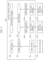
FIG. 2 is a block diagram showing a functional configuration ofanomaly detection system 200 according to the present embodiment. - As shown in
FIG. 2 ,anomaly detection system 200 includesstate obtainer 201,information obtainers state estimators environment manager 204,state selector 205,alert issuer 206, andstate comparer 207. -
State obtainer 201 receives state information that is transmitted from monitoredtarget 102 and that indicates a state of this monitoredtarget 102. According to the present embodiment,state obtainer 201 obtains the current position of monitoredtarget 102 as a state of this monitoredtarget 102.State obtainer 201 includes, for example, a communication module (a communication circuit).State obtainer 201 is one example of a first obtainer. -
Information obtainer 202a receives information thatexternal information source 103a has transmitted, andinformation obtainer 202b receives information thatexternal information source 103b has transmitted. Specifically,information obtainer 202a obtains, fromexternal information source 103a, sensing information (e.g., first sensing information) indicating the sensing result of the sensing thatexternal information source 103a has performed on monitoredtarget 102, andinformation obtainer 202b obtains, fromexternal information source 103b, sensing information (e.g., second sensing information) indicating the sensing result of the sensing thatexternal information source 103b has performed on monitoredtarget 102. The first sensing information and the second sensing information are sensing information of different types. -
Information obtainers Information obtainers -
State estimator 203a estimates the state of monitored target 102 (one example of a first state) based on the information thatinformation obtainer 202a has obtained, andstate estimator 203b estimates the state of monitored target 102 (one example of a second state) based on the information thatinformation obtainer 202b has obtained. According to the present embodiment,state estimators target 102. Sensing information used to estimate the first state and sensing information used to estimate the second state are information of different types, and thus the first state and the second state may indicate different states (e.g., different positions). - For example, the information that
information obtainer 202a obtains is any one information selected from, for example, video information, audio information, a sensor value, and time information, and the information thatinformation obtainer 202b obtains is information other than the one information selected from, for example, the video information, the audio information, the sensor value, and the time information. In other words, the information thatinformation obtainer 202a obtains (the first sensing information) and the information thatinformation obtainer 202b obtains (the second sensing information) are information of different types. -
State estimator 203a estimates, for example, the first state with the use of a machine learning model, andstate estimator 203b estimates, for example, the second state with the use of another machine learning model. A machine learning model is trained in advance to output a state of monitoredtarget 102 in response to receiving an input of sensing information. The machine learning model thatstate estimator 203a uses and the machine learning model thatstate estimator 203b uses are machine learning models trained with the use of different items of input information. -
Environment manager 204 manages, as environmental information (seeFIG. 5 , which will be described later), the accuracy of states thatstate estimators state estimators target 102 has been performed and the accuracy with whichstate estimators target 102 in that environment. The environment as used herein is, for example, the time. Alternatively, the environment may be, for example but is not limited to, the weather or the brightness of the surroundings of monitoredtarget 102. For example, environmental information may include the estimation accuracy of the first state and of the second state with respect to time. -
State selector 205 selects, from the estimated states of monitoredtarget 102 thatstate estimators environment manager 204 manages.State selector 205 selects one of the first state or the second state with the use of the environmental information and outputs the selected one of the first state or the second state as the estimated state (estimated state information). - Herein,
state selector 205 is one example of a state determiner. The state determiner is not limited to estimating the state of monitoredtarget 102 by selecting a state. The state determiner may calculate one state from the first state and the second state with the use of the environmental information and output the calculated one state as the estimated state. The state determiner may, for example, perform a weighting computation on the first state and the second state with the use of the environmental information and output one of the states subjected to the weighting computation as the estimated state. -
State comparer 207 compares the state thatstate obtainer 201 has obtained (state information) and the estimated state obtained from state selector 205 (estimated state information). The estimated state information is information that is based at least on the first state, and according to the present embodiment, the estimated state information is information that is based on the first state and the second state.State comparer 207 compares, for example, the state of monitoredtarget 102 thatstate obtainer 201 has obtained and the estimated state of monitoredtarget 102 thatstate selector 205 has selected. If there is a difference of a predetermined magnitude or more between the aforementioned state and the aforementioned estimated state,state comparer 207 determines that there is an anomaly and notifiesalert issuer 206 that an anomaly has been detected. - Based on the result of the comparison by
state comparer 207,alert issuer 206 alerts (issues an alert to) a monitor ofremote monitoring system 101 that an anomaly has occurred. - Herein, the estimation accuracy that
environment manager 204 manages and with whichstate estimators estimator training system 300 has performed.Environment manager 204 may determine the estimation accuracy of the estimated states thatstate estimators FIG. 3 ). The estimation accuracy may be determined, for example, with the use of a table indicating a correspondence relationship between the estimation accuracy and the information indicating the estimation accuracy. -
Remote monitoring system 101 according to the present embodiment detects an alteration made by an attacker by estimating the state of a robot that serves as monitoredtarget 102 with the use of information (sensing information) obtained from, for example,external information sources remote monitoring system 101 can maintain a high estimation accuracy in a variety of environments by selecting, from among a plurality of states, a state estimated with the use of the optimal information obtained from, for example,external information sources target 102 operates. - Next, a configuration of state
estimator training system 300 will be described.FIG. 3 is a block diagram showing a functional configuration of stateestimator training system 300 according to the present embodiment.FIG. 3 shows a configuration for performing a process of training onestate estimator 303. It is to be noted that, althoughFIG. 3 showsexternal information source 103 for the sake of convenience, stateestimator training system 300 obtains sensing information from each ofexternal information sources - As shown in
FIG. 3 , stateestimator training system 300 includesstate obtainer 201a,information obtainer 202c,state trainer 301,environment manager 302, andstate estimator 303. -
State obtainer 201a has a configuration the same as the configuration ofstate obtainer 201 ofanomaly detection system 200.State obtainer 201a obtains state information from monitoredtarget 102. Meanwhile,information obtainer 202c has a configuration the same as the configuration of information obtainers 202a and 202b ofanomaly detection system 200.Information obtainer 202c obtains sensing information fromexternal information source 103. -
State estimator 303 estimates the state of monitoredtarget 102 based on the information ofexternal information source 103 obtained frominformation obtainer 202c and outputs the estimated state and the time at whichstate estimator 303 has estimated the state of monitoredtarget 102 tostate trainer 301. -
State trainer 301 calculates the estimation accuracy by comparing the state of monitoredtarget 102 thatstate obtainer 201a has obtained and the estimated state thatstate estimator 303 has estimated and outputs the environment and the calculated estimation accuracy toenvironment manager 302 andstate estimator 303. The estimated state in this example is information that is based, for example, on the difference (an estimation error) between the state of monitoredtarget 102 obtained fromstate obtainer 201a and the estimated state of monitoredtarget 102 obtained fromstate estimator 303. -
Environment manager 302 manages the set of the environment (the time in this example) and the estimation accuracy obtained fromstate trainer 301 as environmental information. - Based on the estimation accuracy obtained from
state trainer 301,state estimator 303 trains the machine learning model to improve the estimation accuracy. - In one example case of training in
state estimator 303 described below, with the use of a regression model in which the information obtained frominformation obtainer 202c serves as an explanatory variable and the state of monitoredtarget 102 serves as a dependent variable, and with an objective function served by the sum of squared error which is the sum of squared values of the difference between the state obtained fromstate obtainer 201a and the state of monitoredtarget 102 thatstate estimator 303 has estimated,state estimator 303 trains the machine learning model so as to minimize the sum of squared error. Herein, the sum of squared error is one example of the estimation accuracy. -
State estimator 303 estimates the state of monitoredtarget 102 based on an intrinsic parameter, such as a weight or a bias of a regression model, and the information ofexternal information source 103 obtained frominformation obtainer 202c and outputs the estimated state and the time at whichstate estimator 303 has estimated the state of monitoredtarget 102 tostate trainer 301. - Based on the state of monitored
target 102 obtained fromstate obtainer 201a and the estimated state obtained fromstate estimator 303,state trainer 301 calculates the sum of squared error, which is the objective function, to calculate the estimation accuracy and outputs the environment (the time in this example) and the calculated estimation accuracy toenvironment manager 302 andstate estimator 303. -
Environment manager 302 manages the set of the environment and the estimation accuracy obtained fromstate trainer 301 as environmental information. - Based on the set of the intrinsic parameter used in a previous instance of estimation and the estimation accuracy obtained from
state trainer 301 and the set of the intrinsic parameter used in the current instance of estimation and the estimation accuracy obtained fromstate trainer 301,state estimator 303 calculates, with the use of a differential equation, the slope of the change in the estimation accuracy observed as the intrinsic parameter has been changed and updates the intrinsic parameter so as to bring the slope to a negative value, that is, to reduce the sum of squared error. - Training in
state trainer 301 is repeated with the intrinsic parameter ofstate estimator 303 updated, the intrinsic parameter is adjusted so that the state of monitoredtarget 102 can be estimated with higher accuracy, andenvironment manager 302 manages the estimation accuracy for each environment. Then, stateestimator training system 300 can relay the training result toanomaly detection system 200 by replacing the trained parameter ofstate estimator 303 and the trained environmental information thatenvironment manager 204 manages with, respectively, the parameters (the intrinsic parameters) ofstate estimators anomaly detection system 200 and the environmental information ofenvironment manager 204. - Herein, the adjustment (e.g., an update) to the intrinsic parameter of the machine learning model and the update of the environmental information are performed, for example, as one set. The environmental information includes the estimation accuracy observed with the adjusted intrinsic parameter. In this manner, the environmental information may be generated based on the process of training the machine learning model.
- Herein, in a case in which
remote monitoring system 101 includes a part of the functions of stateestimator training system 300,state trainer 301 may calculate information (e.g., the sum of squared error) indicating the estimation accuracy of at least one of the first state or the second state of monitoredtarget 102 that stateestimator training system 300 has estimated, based on the state of monitoredtarget 102 thatstate obtainer 201 has obtained and the at least one of the first state or the second state of monitoredtarget 102 that stateestimator training system 300 has estimated. Then,state trainer 301 may output the information indicating the calculated estimation accuracy tostate estimators environment manager 204. - Herein,
state trainer 301 may output the information indicating the calculated estimation accuracy tostate estimators environment manager 204 before monitoredtarget 102 is put into operation. Alternatively,state trainer 301 may output the information indicating the calculated estimation accuracy tostate estimators environment manager 204 while monitoredtarget 102 is in operation. While monitoredtarget 102 is in operation, training is performed with the use of the state of monitoredtarget 102 thatstate obtainer 201 has obtained when no anomaly has been detected bystate comparer 207 and the estimated state that each ofstate estimators - Next, a process of training for the accuracy of estimating the state of monitored
target 102 in stateestimator training system 300 will be described.FIG. 4 is a flowchart showing a training process (a remote monitoring method) in stateestimator training system 300 according to the present embodiment. - As shown in
FIG. 4 , first, training (a training process) is performed in state estimator training system 300 (S401). At step S401, as the training,state estimator 303 estimates the state of monitoredtarget 102 with the use of the state thatinformation obtainer 202c has extracted and outputs the estimated state tostate trainer 301.State trainer 301 compares the state thatstate estimator 303 has estimated and the state of monitoredtarget 102 thatstate obtainer 201 has extracted, calculates the estimation accuracy, and outputs the calculated estimation accuracy tostate estimator 303.State estimator 303 performs a process of adjusting the intrinsic parameter so as to improve the estimation accuracy based on the estimation accuracy thatstate trainer 301 has calculated. These processes are repeated a predetermined number of times at step S401. - State
estimator training system 300 determines whether the estimation accuracy is sufficient (S402). Stateestimator training system 300 determines whether the estimation accuracy thatenvironment manager 302 holds exceeds the accuracy set in advance. - If state
estimator training system 300 has determined that the estimation accuracy is sufficient (YES at S402), stateestimator training system 300 replaces the intrinsic parameter trained instate estimator 303 and the trained environmental information thatenvironment manager 302 manages with, respectively, the intrinsic parameters ofstate estimators anomaly detection system 200 and the environmental information ofenvironment manager 204, and the model is used then in anomaly detection system 200 (S403). - If state
estimator training system 300 has determined that the estimation accuracy is not sufficient (NO at S402), stateestimator training system 300 determines that the improvement in the estimation accuracy ofstate estimator 303 is not likely and revises the training method (S404), and then stateestimator training system 300 executes step S401 again. - In one example of the training method, with
state estimator 303 being a regression model in which the information obtained frominformation obtainer 202c serves as an explanatory variable and the state of monitoredtarget 102 serves as a dependent variable,state trainer 301 trains the regression model with the use of the least-squares method so as to minimize the difference between the estimated state of monitoredtarget 102 thatstate estimator 303 has estimated and the state obtained fromstate obtainer 201a. - If state
estimator training system 300 has determined that the estimation accuracy observed after the training is not sufficient and the improvement in the estimation accuracy is not likely,state trainer 301, in the revised training method, revises a mathematical model by, for example, changing the regression model from the linear regression to the regression tree and improves the estimation accuracy until the error falls within a permissible range. - As described above, monitoring system 100 (or remote monitoring system 101) is provided with a training mode in which the machine learning model is trained. Furthermore, the training mode is executed, for example, within a space in which monitored
target 102 is used. - Next, the contents that
environment manager 204 ofanomaly detection system 200 manages will be described.FIG. 5 is a diagram showing one example of an environmental information table thatenvironment manager 204 according to the present embodiment manages. - As shown in
FIG. 5 , an environmental information table includesenvironment 501 andestimation accuracy 502.Estimation accuracy 502 includes the estimation accuracy ofstate estimator 203a and the estimation accuracy ofstate estimator 203b. -
Environment 501 indicates the environment in whichstate estimators FIG. 5 ,environment 501 is the time, andestimation accuracy 502 with respect to time is shown. -
Estimation accuracy 502 indicates the estimation accuracy inenvironment 501.Estimation accuracy 502 indicates, in percentage, the ratio between the estimation accuracy ofstate estimator 203a and the estimation accuracy ofstate estimator 203b. InFIG. 5 , the estimation accuracy is indicated by the ratio in order to show the difference in accuracy betweenstate estimators state estimators - For example, in the case of the example shown in
FIG. 5 , the estimation accuracy of the state of monitoredtarget 102 thatstate estimator 203a has estimated at 12:00 based on the sensing information ofexternal information source 103a is 80%, and the estimation accuracy of the state of monitoredtarget 102 thatstate estimator 203b has estimated at 12:00 based on the sensing information ofexternal information source 103b is 20%. Based on the above, it can be understood that, at 12:00, the estimation accuracy of the state of monitoredtarget 102 thatstate estimator 203a has estimated is higher than the estimation accuracy of the state of monitoredtarget 102 thatstate estimator 203b has estimated. - An environmental information table may be prepared in advance, may be created through training in state
estimator training system 300, or may be created based on the environmental information ofenvironment manager 302 of stateestimator training system 300. - If an environmental information table is to be created through the training in state
estimator training system 300, the environment held when an estimation is made is recorded inenvironment 501, and the estimation accuracy observed in that instance of estimation is recorded inestimation accuracy 502. - Next, a process performed by
remote monitoring system 101 and a process performed bystate selector 205 will be described. First, a process performed byremote monitoring system 101 will be described.FIG. 6A is a flowchart showing a process (a remote monitoring method) performed byremote monitoring system 101 according to the present embodiment. - As shown in
FIG. 6A , first,state obtainer 201 obtains, from monitoredtarget 102, state information indicating the state of this monitored target 102 (S601). The state information includes time information that indicates the time at which, for example, a sensor in monitoredtarget 102 has performed sensing. - Next,
information obtainers external information sources information obtainer 202a obtains, fromexternal information source 103a, first sensing information as the information for estimation, andinformation obtainer 202b obtains, fromexternal information source 103b, second sensing information as the information for estimation. - Herein, there is no particular limitation on the timing at which the first sensing information and the second sensing information are obtained, and the first sensing information and the second sensing information may be obtained, for example, at predetermined intervals. Furthermore, the first sensing information and the second sensing information may be obtained synchronously. For example, the first sensing information and the second sensing information are items of information obtained through sensing performed at the time within a predetermined time difference (e.g., within a few seconds to a few minutes) from the time indicated by the time information included in the state information.
- Next,
state estimators target 102 based on each of the two or more items of information for estimation (S603). Specifically,state estimator 203a obtains, as the estimation result, the state of monitored target 102 (the first state) served by the output obtained when the first sensing information is input to the machine learning model. Meanwhile,state estimator 203b obtains, as the estimation result, the state of monitored target 102 (the second state) served by the output obtained when the second sensing information is input to the machine learning model. The first state and the second state as used herein are each information indicating the current position (e.g., the current position coordinates) of monitoredtarget 102. -
State estimators state selector 205. - Next,
state selector 205 determines one state of monitoredtarget 102 from among two or more estimated states of monitored target 102 (S604). According to the present embodiment,state selector 205 selects either one of the first state and the second state that has a higher estimation accuracy based on the environmental information and determines the selected state as the estimated state of monitoredtarget 102.State selector 205 obtains, from the environmental information table, the estimation accuracy of each ofstate estimators state selector 205 selects the one with a higher estimation accuracy from the first state and the second state. -
State selector 205 outputs the selected estimated state of monitoredtarget 102 tostate comparer 207. - Next,
state comparer 207 determines whether the difference between the state thatstate obtainer 201 has obtained from monitoredtarget 102 and the estimated state is smaller than or equal to a threshold (S605). The threshold is set in advance. - Next, if
state comparer 207 has determined that the difference is smaller than or equal to the threshold (YES at S605), this means that the state obtained from monitoredtarget 102 is within a normal range, and thusstate comparer 207 terminates the process. That the determination of YES is made at step S605 means that the state of monitoredtarget 102 is not altered in monitoredtarget 102. Meanwhile, ifstate comparer 207 determines that the difference is neither smaller than nor equal to the threshold (NO at S605),state comparer 207 outputs, to alertissuer 206, information indicating that an anomaly has been detected. That the determination of NO is made at step S605 means that the state of monitoredtarget 102 has been altered in monitoredtarget 102 or that it is highly likely that such an alteration has been made. - Next,
alert issuer 206 issues, to the monitor ofremote monitoring system 101, an alert indicating that an anomaly has been detected (S606). For example, such an alert may be issued through display on a display device, through an audible output from an audio output device, through light emission from a light emitting device, through another method, or through a combination of any of the above. - Next, a process performed by
state selector 205 will be described.FIG. 6B is a flowchart showing a process (a remote monitoring method) performed bystate selector 205 according to the present embodiment.FIG. 6B is a flowchart showing the details of step S604 ofFIG. 6A . - As shown in
FIG. 6B ,state selector 205, for example, obtains the states thatstate estimators -
State selector 205 obtains, fromenvironment manager 204, environmental information that links the environment and the estimation accuracy ofstate estimators -
State selector 205 makes the final selection of an estimated state based on the estimated states, the environment in which these states have been estimated, and the estimation accuracy in that environment (S613). In the environmental information shown inFIG. 5 , the estimation accuracy ofstate estimator 203a at 12:00 is 80%, and the estimation accuracy ofstate estimator 203b at 12:00 is 20%. Therefore,state selector 205 selects the state with the higher, 80%, estimation accuracy thatstate estimator 203a has estimated. This selection is one example of determining one state of monitoredtarget 102. - Herein, aside from selecting the state with the highest estimation accuracy,
state selector 205 may weight each estimated state based on its estimation accuracy and calculate a newly estimated state in accordance with the weight. For example, a newly estimated state may be calculated such that a higher weight is given to a higher estimation accuracy. - Next, an anomaly detection system employed in a case in which a monitored target is a robot that moves autonomously will be described. In the case described according to the present embodiment, whether the position information sent from a robot has been altered is determined.
-
FIG. 7 is a block diagram showing a functional configuration ofanomaly detection system 700 according to the present embodiment. - As shown in
FIG. 7 ,anomaly detection system 700 includesstate obtainer 702, information obtainers 711 and 721,state estimators environment manager 704,state selector 703,alert issuer 206, andstate comparer 207. - A monitored target that
anomaly detection system 700 monitors isrobot 701, and external information sources arestationary camera 710 andstationary microphone 720. -
Robot 701 transmits its position information toanomaly detection system 700. Examples of information that can be used as the position information include the measured position information of a global positioning system (GPS) device provided inrobot 701 or the position information estimated by the simultaneous localization and mapping (SLAM) provided inrobot 701. -
Stationary camera 710 is installed at a position wherestationary camera 710 can easily capture an image ofrobot 701, such as at a position near the ceiling of a room, and transmits capturedvideo 713 toanomaly detection system 700.Stationary microphone 720 is installed at a position wherestationary microphone 720 can easily collect sound associated with an activity ofrobot 701, such as at a position near the entrance within a room, and transmits collected audio 723 toanomaly detection system 700.Stationary camera 710 is one example of a first sensing device, andstationary microphone 720 is one example of a second sensing device. -
State obtainer 702 receives position information fromrobot 701.State obtainer 702 obtains the position information ofrobot 701 as the state ofrobot 701. -
Information obtainer 711 receivesvideo 713 thatstationary camera 710 has transmitted and extracts video data to be used to estimate a state. Examples of such video data include a bitmap image converted to grayscale.Video 713 is one example of first sensing information. -
State estimator 712 estimates the position ofrobot 701 with the use of the video data thatinformation obtainer 711 has extracted and outputs the estimated position as estimatedstate 714. -
Information obtainer 721 receives audio 723 thatstationary microphone 720 has transmitted and extracts audio data to be used to estimate a state. Examples of such audio data include pulse code modulation (PCM) data divided into predetermined cycles and subjected to a band pass filtering process so that only the frequency that allows for easy recognition of activity sound ofrobot 701 is included, but this is not a limiting example.Audio 723 is one example of second sensing information. -
State estimator 722 estimates the position ofrobot 701 with the use of the audio data thatinformation obtainer 721 has extracted and outputs the estimated position as estimatedstate 724. -
Environment manager 704 manages environmental information 705 (seeFIG. 8 ) that holds the estimation accuracy ofstationary camera 710 with respect to time and the estimation accuracy ofstationary microphone 720 with respect to time. -
State selector 703 selects, from between estimatedstate 714 and estimatedstate 724, the estimated state with a higher estimation accuracy, in accordance withenvironmental information 705 managed byenvironment manager 704. -
Alert issuer 206 has a configuration the same as the configuration ofalert issuer 206 ofanomaly detection system 200. -
State comparer 207 compares the position information thatstate obtainer 702 has extracted and the estimated state (the estimated position information) thatstate selector 703 has selected. If there is a difference of a predetermined magnitude or more between the aforementioned position information and the aforementioned estimated state,state comparer 207 determines that there is an anomaly and informsalert issuer 206 of the detected anomaly. - To be more specific,
state comparer 207 obtains, fromstate obtainer 702, the position information ofrobot 701 in the latitude and longitude format and obtains, fromstate selector 703, the estimated position information ofrobot 701 in the latitude and longitude format.State comparer 207 then calculates the distance between the two items of position information, and if the calculated distance exceeds a threshold set in advance,state comparer 207 determines that there is an anomaly. - In a case in which
robot 701 works in a facility, such as an office building or a commercial establishment, the illuminance within the facility is expected to be high and thenoise surrounding robot 701 is expected to be large during the time range in whichrobot 701 works, while the illuminance within the facility is expected to be low and thenoise surrounding robot 701 is expected to be small outside the time range in whichrobot 701 works. - In such a case, a higher estimation accuracy is highly likely to be obtained if the state of
robot 701 is estimated based onvideo 713 ofstationary camera 710 during the time range in whichrobot 701 works and the state ofrobot 701 is estimated based onaudio 723 ofstationary microphone 720 outside the time range in whichrobot 701 works. -
FIG. 8 is a diagram showing one example of an environmental information table thatenvironment manager 704 of the anomaly detection system according to the present embodiment manages. - According to the environmental information table shown in
FIG. 8 , the estimation accuracy ofstate estimator 712 is set high during the time range from 12:00 to 22:00, which is the time range in whichrobot 701 works, and the estimation accuracy ofstate estimator 722 is set high during the time range from 22:00 to 12:00, which is outside the time range in whichrobot 701 works. -
State selector 703 selects, as the position ofrobot 701, the position with a higher estimation accuracy underestimation accuracy 1002 at a predetermined time underenvironment 1001 in the environmental information table, and thusstate selector 703 can select an optimal estimated state corresponding to any change in time. - The environmental information table shown in
FIG. 8 may be created from the environmental information inenvironment manager 302 of stateestimator training system 300 afterstate estimators estimator training system 300. - In the description according to the present embodiment, there is only one
stationary camera 710 and only onestationary microphone 720 in order to simplify the description. Alternatively, there may be a plurality ofstationary cameras 710 and a plurality ofstationary microphones 720. - Next, an anomaly detection system employed in a case in which a monitored target is a security robot that performs a security task will be described. In the case described according to the present embodiment, whether the position information sent from a security robot has been altered is determined.
-
FIG. 9 is a block diagram showing a functional configuration ofanomaly detection system 800 according to the present embodiment. - As shown in
FIG. 9 ,anomaly detection system 800 includesstate obtainer 802, information obtainers 811 and 821,state estimators environment manager 804,state selector 803,alert issuer 206, andstate comparer 207. - A monitored target that
anomaly detection system 800 monitors issecurity robot 801, and external information sources arestationary camera 810 andilluminance sensor 820. -
Security robot 801 transmits its position information toanomaly detection system 800. Examples of information that can be used as the position information include the measured position information of a GPS device provided insecurity robot 801 or the position information estimated by the SLAM provided insecurity robot 801. -
Stationary camera 810 is installed at a position wherestationary camera 810 can easily capture an image ofsecurity robot 801, such as at a position near the ceiling of a room, and transmits capturedvideo 813 toanomaly detection system 800.Illuminance sensor 820 is installed on a moving path ofsecurity robot 801 and transmits obtainedilluminance value 823 toanomaly detection system 800.Stationary camera 810 is one example of a first sensing device, andilluminance sensor 820 is one example of a second sensing device. -
State obtainer 802 receives position information fromsecurity robot 801. -
Information obtainer 811 receivesvideo 813 thatstationary camera 810 has transmitted and extracts video data to be used to estimate a state. Examples of such video data include a bitmap image converted to grayscale.Video 813 is one example of first sensing information. -
State estimator 812 estimates the position ofsecurity robot 801 with the use of the video data thatinformation obtainer 811 has extracted and outputs the estimated position as estimatedstate 814. -
Information obtainer 821 receivesilluminance value 823 thatilluminance sensor 820 has transmitted and extracts illuminance data to be used to estimate a state. The illuminance data is a value obtained by converting the illuminance value to lux, which is the unit for brightness.Illuminance value 823 is one example of second sensing information. -
State estimator 822 estimates the position ofsecurity robot 801 with the use of the illuminance data thatinformation obtainer 821 has extracted and outputs the estimated position as estimatedstate 824. - Specifically, when
security robot 801 conducts a patrol while lights in the surrounding area are not on during the nighttime, for example,security robot 801 itself illuminates the surrounding area. Therefore,information obtainer 821 obtains the illuminance value ofilluminance sensor 820, and based on the obtained illuminance value,state estimator 822 estimates how far awaysecurity robot 801 is located. -
Environment manager 804 manages environmental information 805 (seeFIG. 10 ) that holds the estimation accuracy ofstationary camera 810 with respect to time and the estimation accuracy ofilluminance sensor 820 with respect to time. -
State selector 803 selects, from between estimatedstate 814 and estimatedstate 824, the estimated state with a higher estimation accuracy, in accordance with environmental information 805 managed byenvironment manager 804. -
Alert issuer 206 has a configuration the same as the configuration ofalert issuer 206 ofanomaly detection system 200. -
State comparer 207 compares the position information thatstate obtainer 802 has extracted and the estimated state (the estimated position information) thatstate selector 803 has selected. If there is a difference of a predetermined magnitude or more between the aforementioned position information and the aforementioned estimated state,state comparer 207 determines that there is an anomaly and informsalert issuer 206 of the detected anomaly. - In
security robot 801, in one contemplated case, whensecurity robot 801 is on patrol as a part of a security task,security robot 801 makes a recording with an embedded camera ofsecurity robot 801 during the patrol, and that recording serves as evidence of that patrol. Therefore, the light ofsecurity robot 801 is turned on whilesecurity robot 801 conducts a patrol during the nighttime in order to ensure or secure the illumination necessary for making a recording, and thus the illuminance value of the area surroundingsecurity robot 801 becomes high. -
FIG. 10 is a diagram showing one example of an environmental information table thatenvironment manager 804 ofanomaly detection system 800 according to the present embodiment manages. - According to the environmental information table shown in
FIG. 10 , the estimation accuracy ofstate estimator 812 is set high during the time range from 08:00 to 20:00, which is the time range in which the surroundings is bright as in the daytime and an image ofsecurity robot 801 is captured clearly in the video ofstationary camera 810, and the estimation accuracy ofstate estimator 822 is set high during the time range from 22:00 to 08:00, which is the time range in which an image ofsecurity robot 801 is not captured clearly in the video ofstationary camera 810 since its surroundings are dark as in the nighttime but any change in the illuminance value associated with the light turned on by the security robot can be detected more easily. -
State selector 803 selects, as the position ofsecurity robot 801, the position with a higher estimation accuracy underestimation accuracy 1102 at a predetermined time underenvironment 1101 in the environmental information table, and thusstate selector 803 can select an optimal estimated state corresponding to any change in time. - The environmental information table may be created from the environmental information in
environment manager 302 of stateestimator training system 300 afterstate estimators estimator training system 300. - In the description according to the present embodiment, there is only one
stationary camera 810 and only oneilluminance sensor 820 in order to simplify the description. Alternatively, there may be a plurality ofstationary cameras 810 and a plurality ofilluminance sensors 820. - Next, an anomaly detection system employed in a case in which a monitored target is a cleaning robot that performs a cleaning task will be described. In the case described according to the present embodiment, whether the position information sent from a cleaning robot has been altered is determined.
-
FIG. 11 is a block diagram showing a functional configuration ofanomaly detection system 900 according to the present embodiment. - As shown in
FIG. 11 ,anomaly detection system 900 includesstate obtainer 902, information obtainers 911 and 921,state estimators environment manager 904,state selector 903,alert issuer 206, andstate comparer 207. - A monitored target that
anomaly detection system 900 monitors is cleaningrobot 901, and external information sources arestationary camera 910 anddust sensor 920. -
Cleaning robot 901 transmits its position information toanomaly detection system 900. Examples of information that can be used as the position information include the measured position information of a GPS device provided in cleaningrobot 901 or the position information estimated by the SLAM provided in cleaningrobot 901. -
Stationary camera 910 is installed at a position wherestationary camera 910 can easily capture an image of cleaningrobot 901, such as at a position near the ceiling of a room, and transmits captured video 913 toanomaly detection system 900.Dust sensor 920 is installed at a position around an area where cleaningrobot 901 performs a cleaning task and transmits obtainedsensor value 923 toanomaly detection system 900.Stationary camera 910 is one example of a first sensing device, anddust sensor 920 is one example of a second sensing device. -
State obtainer 902 receives position information from cleaningrobot 901. -
Information obtainer 911 receives video 913 thatstationary camera 910 has transmitted and extracts video data to be used to estimate a state. Examples of such video data include a bitmap image converted to grayscale. Video 913 is one example of first sensing information. -
State estimator 912 estimates the position of cleaningrobot 901 with the use of the video data thatinformation obtainer 911 has extracted and outputs the estimated position as estimatedstate 914. -
Information obtainer 921 receivessensor value 923 thatdust sensor 920 has transmitted and extracts a sensor value to be used to estimate a state. Examples of such a sensor value include the amount of particles present in the atmosphere.Sensor value 923 is one example of second sensing information. -
State estimator 922 estimates the position of cleaningrobot 901 with the use of the sensor data thatinformation obtainer 921 has extracted and outputs the estimated position as estimatedstate 924. - Specifically, cleaning
robot 901 performs a cleaning task while people who engage in activities in its surroundings are not present, such as during the nighttime. The cleaning task that cleaningrobot 901 performs causes dust to rise in its surroundings. Thus,information obtainer 921 obtains the sensor value fromdust sensor 920, and based on the obtained sensor value,state estimator 922 estimates how far away cleaningrobot 901 is located. -
Environment manager 904 manages environmental information 905 (seeFIG. 12 ) that holds the estimation accuracy ofstationary camera 910 with respect to time and the estimation accuracy ofdust sensor 920 with respect to time. -
State selector 903 selects, from between estimatedstate 914 and estimatedstate 924, the estimated state with a higher estimation accuracy, in accordance withenvironmental information 905 managed byenvironment manager 904. -
Alert issuer 206 has a configuration the same as the configuration ofalert issuer 206 ofanomaly detection system 200. -
State comparer 207 compares the position information thatstate obtainer 902 has extracted and the estimated state (the estimated position information) thatstate selector 903 has selected. If there is a difference of a predetermined magnitude or more between the aforementioned position information and the aforementioned estimated state,state comparer 207 determines that there is an anomaly and informsalert issuer 206 of the detected anomaly. - When cleaning
robot 901 performs a cleaning task, dust may rise in the atmosphere. Therefore, the sensor value of the dust sensor changes a great deal in the surroundings of cleaningrobot 901 during the cleaning task. -
FIG. 12 is a diagram showing one example of an environmental information table thatenvironment manager 904 ofanomaly detection system 900 according to the present embodiment manages. - According to the environmental information table shown in
FIG. 12 , the estimation accuracy ofstate estimator 912 is set high during the time range from 07:00 to 21:00, which is the time range in which the surroundings of cleaningrobot 901 is bright as in the daytime and an image of cleaningrobot 901 is captured clearly in the video ofstationary camera 910, and the estimation accuracy ofstate estimator 922 is set high during the time range from 21:00 to 07:00, which is the time range in which an image of cleaningrobot 901 is not captured clearly in the vide ofstationary camera 910 since the surroundings of cleaningrobot 901 is dark as in the nighttime. -
State selector 903 selects, as the position of cleaningrobot 901, the position with a higher estimation accuracy underestimation accuracy 1202 at a predetermined time underenvironment 1201 in the environmental information table, and thusstate selector 903 can select an optimal estimated state corresponding to any change in time. - The environmental information table may be created from the environmental information in
environment manager 302 of stateestimator training system 300 afterstate estimators estimator training system 300. - In the description according to the present embodiment, there is only one
stationary camera 910 and only onedust sensor 920 in order to simplify the description. Alternatively, there may be a plurality ofstationary cameras 910 and a plurality ofdust sensors 920. - Thus far, the remote monitoring system and so forth according to one or more aspects have been described based on the embodiments, but these embodiments do not limit the present disclosure. Unless departing from the spirit of the present disclosure, an embodiment obtained by making various modifications that are conceivable by a person skilled in the art to the embodiments or an embodiment obtained by combining the constituent elements in different embodiments may also be encompassed by the present disclosure.
- For example, a monitored target according to each of the foregoing embodiments may be a mobile body used indoors or a mobile body used outdoors.
- Furthermore, the monitoring system according to each of the foregoing embodiments may include only one external information source. In this case, an anomaly detection system does not need to include a state selector. Furthermore, an environment manager may output environmental information to a state comparer, and a state comparer may compare state information and estimated state information based on environmental information. A state comparer may, for example, change the threshold against which the difference between state information and estimated state information is compared, in accordance with environmental information. For example, a state comparer may change the threshold to a higher value as the estimation accuracy indicated by environmental information is higher.
- Furthermore, in the examples illustrated in the foregoing embodiments, the sum of squared error is illustrated as the loss function. The loss function, however, is not limited to the sum of squared error, and any loss functions may be used.
- Furthermore, in the examples described according to Embodiments 2 to 4 above, a stationary camera is used as a first sensing device, but this is not a limiting example. Each of a first sensing device and a second sensing device may be any device that can obtain different sensing information, and a sensing device other than a stationary camera, for example, may also be used.
- In each of the foregoing embodiments, the constituent elements may each be implemented by a dedicated piece of hardware or may each be implemented through the execution of a software program suitable for a corresponding constituent element. The constituent elements may each be implemented as a program executing unit, such as a CPU or a processor, reads out a software program recorded on a recording medium, such as a hard disk or a semiconductor memory, and executes the software program.
- The order of executing the steps in each flowchart is for illustrating an example serving to describe the present disclosure in concrete terms, and the order may differ from the ones described above. Furthermore, one or more of the steps described above may be executed simultaneously (in parallel) with another step, or one or more of the steps described above do not have to be executed.
- The divisions of the functional blocks in the block diagrams are merely examples. A plurality of functional blocks may be implemented as a single functional block, a single functional block may be divided into a plurality of functional blocks, or one or more of the functions may be transferred to another functional block. Furthermore, the functions of a plurality of functional blocks having similar functions may be processed in parallel or through time division by a single piece of hardware or software.
- Furthermore, the remote monitoring system according to each of the foregoing embodiments may be implemented in the form of a single device or in the form of a plurality of devices. In a case in which a remote monitoring system is implemented by a plurality of devices, the constituent elements of the remote monitoring system may be distributed over the plurality of devices in any manner. In a case in which a remote monitoring system is implemented by a plurality of devices, there is no particular limitation on the method of communication between the plurality of devices, and such communication may be wireless communication or wired communication. The devices may also communicate with each other through a combination of wireless communication and wired communication.
- Furthermore, each constituent element described according to the foregoing embodiments and so forth may be implement by software or may typically be implemented in the form of an LSI circuit, which is an integrated circuit. The constituent elements may each be implemented by a single chip, or a part or the whole of the constituent elements may be implemented by a single chip. Although an LSI circuit is illustrated as an example in the above, depending on the difference in the degree of integration, such a circuit may also be called an IC, a system LSI circuit, a super LSI circuit, or an ultra LSI circuit. The techniques for circuit integration are not limited to LSI, and an integrated circuit may be implemented by a dedicated circuit (e.g., a general purpose circuit that executes a dedicated program) or by a general purpose processor. A field programmable gate array (FPGA) that can be programmed after an LSI circuit has been manufactured or a reconfigurable processor in which the connections or the settings of the circuit cells within an LSI circuit can be reconfigured may also be used. Furthermore, when a technique for circuit integration that replaces LSI appears through the advancement in the semiconductor technology or through a derived different technique, the constituent elements may be integrated with the use of such different techniques.
- A system LSI circuit is an ultra-multifunctional LSI circuit manufactured by integrating a plurality of processors on a single chip, and is, specifically, a computer system that includes, for example, a microprocessor, a read only memory (ROM), or a random access memory (RAM). The ROM stores a computer program. The microprocessor operates in accordance with the computer program, and thus the system LSI circuit implements its functions.
- Furthermore, one aspect of the present disclosure may be a computer program that causes a computer to execute each of the characteristic steps included in the remote monitoring method indicated in any of
FIG. 4 ,FIG. 6A , andFIG. 6B . - Furthermore, for example, such a program may be a program to be executed by a computer. One aspect of the present disclosure may be a non-transitory computer readable recording medium having such a program recorded thereon. For example, such a program may be recorded on a recording medium, which then may be distributed. For example, a distributed program can be installed onto a device including another processor, and the program can be executed by this processor. Thus, the device can perform each of the processes described above.
- Through the description of the foregoing embodiments, the following techniques are disclosed.
- A remote monitoring system that detects an anomaly in a state of a monitored target that operates autonomously, the remote monitoring system comprising:
- a first obtainer that obtains state information from the monitored target, the state information indicating a state of the monitored target;
- a second obtainer that obtains first sensing information from a first sensing device, the first sensing device being provided outside the monitored target and performing sensing of the monitored target, the first sensing information indicating a result of the sensing of the monitored target;
- a state estimator that estimates a first state based on the first sensing information that the second obtainer obtains, the first state being the state of the monitored target;
- a state comparer that compares the state information that the first obtainer obtains with estimated state information that is based on the first state of the monitored target that the state estimator estimates; and
- a notifier that notifies a monitor of the remote monitoring system of an occurrence of an anomaly, based on a comparison result of the state comparer.
- The remote monitoring system according to technique 1, wherein
- the second obtainer further obtains second sensing information from a second sensing device, the second sensing information being different from the first sensing information, the second sensing device being provided outside the monitored target and performing sensing of the monitored target, the second sensing information indicating a result of the sensing of the monitored target,
- the state estimator estimates a second state based on the second sensing information that the second obtainer obtains, the second state being the state of the monitored target, and
- the estimated state information is information that is based further on the second state.
- The remote monitoring system according to technique 2, further comprising:
- an environment manager that manages environmental information linking an environment in which sensing of the monitored target is performed and an estimation accuracy of a state that the state estimator estimates; and
- a state determiner that determines one state from between the first state and the second state with use of the environmental information that the environment manager manages, and that outputs the one state determined as the estimated state information.
- The remote monitoring system according to technique 3, wherein the state determiner selects one of the first state or the second state with use of the environmental information, and outputs the one selected as the estimated state information.
- The remote monitoring system according to technique 3, wherein
the state determiner performs a weighting operation on the first state and the second state with use of the environmental information, and outputs a weighted state as the estimated state information. - The remote monitoring system according to any one of techniques 3 to 5, wherein
- the first obtainer obtains a current position of the monitored target as the state,
- the state estimator estimates the current position of the monitored target as the first state and the second state, and
- the environmental information includes an estimation accuracy of the first state and the second state with respect to time.
- The remote monitoring system according to technique 6, wherein
- the monitored target is a robot,
- the first sensing device includes a stationary camera, and
- the second sensing device includes a stationary microphone.
- The remote monitoring system according to technique 6, wherein
- the monitored target is a robot that performs a security task,
- the first sensing device includes a stationary camera, and
- the second sensing device includes an illuminance sensor.
- The remote monitoring system according to technique 6, wherein
- the monitored target is a robot that performs a cleaning task,
- the first sensing device includes a stationary camera, and
- the second sensing device includes a dust sensor.
- The remote monitoring system according to any one of techniques 3 to 9, further comprising:
a state trainer that calculates information indicating an estimation accuracy of at least one of the first state or the second state based on the state of the monitored target that the first obtainer obtains and the at least one of the first state or the second state of the monitored target that the state estimator estimates, and that outputs the information calculated indicating the estimation accuracy to the state estimator and the environment manager. - The remote monitoring system according to
technique 10, wherein
the environment manager determines an estimation accuracy of the state that the state estimator estimates, based on the information that is obtained from the state trainer and indicates the estimation accuracy. - The remote monitoring system according to
technique 10 or 11, wherein
the state trainer outputs the information calculated indicating the estimation accuracy to the state estimator and the environment manager before the monitored target is put into operation. - The remote monitoring system according to any one of
techniques 10 to 12, wherein
the state trainer outputs the information calculated indicating the estimation accuracy to the state estimator and the environment manager while the monitored target is in operation. - The remote monitoring system according to technique 1, further comprising:
- an environment manager that manages environmental information linking an environment in which sensing of the monitored target is performed and an estimation accuracy of a state that the state estimator estimates, wherein
- the state comparer compares the state information with the estimated state information based on the environmental information.
- An anomaly detection system that detects an anomaly in a state of a monitored target that operates autonomously, the anomaly detection system comprising:
- a first obtainer that obtains state information from the monitored target, the state information indicating a state of the monitored target;
- a second obtainer that obtains sensing information from a sensing device, the sensing device being provided outside the monitored target and performing sensing of the monitored target, the sensing information indicating a result of the sensing of the monitored target;
- a state estimator that estimates the state of the monitored target based on the sensing information that the second obtainer obtains; and
- a state comparer that compares the state information that the first obtainer obtains with estimated state information that is based on the state of the monitored target that the state estimator estimates.
- A remote monitoring method of detecting an anomaly in a state of a monitored target that operates autonomously, the remote monitoring method comprising:
- obtaining state information from the monitored target, the state information indicating a state of the monitored target;
- obtaining sensing information from a sensing device, the sensing device being provided outside the monitored target and performing sensing of the monitored target, the sensing information indicating a result of the sensing of the monitored target;
- estimating the state of the monitored target based on the sensing information obtained;
- comparing the state information obtained with estimated state information that is based on the state estimated of the monitored target; and
- notifying a monitor of a remote monitoring system of an occurrence of an anomaly, based on a comparison result of the state information and the estimated state information.
- A program for causing a computer to execute the remote monitoring method according to technique 16.
- The present disclosure finds its effective use in an anomaly detection system that, when remotely monitoring a robot that operates autonomously, determines whether the state that the robot being monitored sends to a remote monitoring system differs from the actual state.
-
- 100
- monitoring system
- 101
- remote monitoring system
- 102
- monitored target
- 103, 103a, 103b
- external information source (sensing device)
- 104
- network
- 200, 700, 800, 900
- anomaly detection system
- 201, 201a, 702, 802, 902
- state obtainer (first obtainer)
- 202, 202a, 202b, 202c, 711,
- 721, 811, 821, 911, 921 information obtainer (second obtainer)
- 203a, 203b, 303, 712, 722, 812, 822, 912, 922
- state estimator
- 204, 302, 704, 804, 904
- environment manager
- 205, 703, 803, 903
- state selector (state determiner)
- 206
- alert issuer
- 207
- state comparer
- 300
- state estimator training system
- 301
- state trainer
- 501, 1001, 1101, 1201
- environment
- 502, 1002, 1102, 1202
- estimation accuracy
- 701
- robot (monitored target)
- 705, 805, 905
- environmental information
- 710, 810, 910
- stationary camera (first sensing device)
- 713, 813, 913
- video (first sensing information)
- 714, 724, 814, 824, 914, 924
- estimated state
- 720
- stationary microphone (second sensing device)
- 723
- audio (second sensing information)
- 801
- security robot (monitored target)
- 820
- illuminance sensor (second sensing device)
- 823
- illuminance value (second sensing information)
- 901
- cleaning robot (monitored target)
- 920
- dust sensor (second sensing device)
- 923
- sensor value (second sensing information)
Claims (17)
- A remote monitoring system that detects an anomaly in a state of a monitored target that operates autonomously, the remote monitoring system comprising:a first obtainer that obtains state information from the monitored target, the state information indicating a state of the monitored target;a second obtainer that obtains first sensing information from a first sensing device, the first sensing device being provided outside the monitored target and performing sensing of the monitored target, the first sensing information indicating a result of the sensing of the monitored target;a state estimator that estimates a first state based on the first sensing information that the second obtainer obtains, the first state being the state of the monitored target;a state comparer that compares the state information that the first obtainer obtains with estimated state information that is based on the first state of the monitored target that the state estimator estimates; anda notifier that notifies a monitor of the remote monitoring system of an occurrence of an anomaly, based on a comparison result of the state comparer.
- The remote monitoring system according to claim 1, whereinthe second obtainer further obtains second sensing information from a second sensing device, the second sensing information being different from the first sensing information, the second sensing device being provided outside the monitored target and performing sensing of the monitored target, the second sensing information indicating a result of the sensing of the monitored target,the state estimator estimates a second state based on the second sensing information that the second obtainer obtains, the second state being the state of the monitored target, andthe estimated state information is information that is based further on the second state.
- The remote monitoring system according to claim 2, further comprising:an environment manager that manages environmental information linking an environment in which sensing of the monitored target is performed and an estimation accuracy of a state that the state estimator estimates; anda state determiner that determines one state from between the first state and the second state with use of the environmental information that the environment manager manages, and that outputs the one state determined as the estimated state information.
- The remote monitoring system according to claim 3, wherein
the state determiner selects one of the first state or the second state with use of the environmental information, and outputs the one selected as the estimated state information. - The remote monitoring system according to claim 3, wherein
the state determiner performs a weighting operation on the first state and the second state with use of the environmental information, and outputs a weighted state as the estimated state information. - The remote monitoring system according to any one of claims 3 to 5, whereinthe first obtainer obtains a current position of the monitored target as the state,the state estimator estimates the current position of the monitored target as the first state and the second state, andthe environmental information includes an estimation accuracy of the first state and the second state with respect to time.
- The remote monitoring system according to claim 6, whereinthe monitored target is a robot,the first sensing device includes a stationary camera, andthe second sensing device includes a stationary microphone.
- The remote monitoring system according to claim 6, whereinthe monitored target is a robot that performs a security task,the first sensing device includes a stationary camera, andthe second sensing device includes an illuminance sensor.
- The remote monitoring system according to claim 6, whereinthe monitored target is a robot that performs a cleaning task,the first sensing device includes a stationary camera, andthe second sensing device includes a dust sensor.
- The remote monitoring system according to any one of claims 3 to 9, further comprising:
a state trainer that calculates information indicating an estimation accuracy of at least one of the first state or the second state based on the state of the monitored target that the first obtainer obtains and the at least one of the first state or the second state of the monitored target that the state estimator estimates, and that outputs the information calculated indicating the estimation accuracy to the state estimator and the environment manager. - The remote monitoring system according to claim 10, wherein
the environment manager determines an estimation accuracy of the state that the state estimator estimates, based on the information that is obtained from the state trainer and indicates the estimation accuracy. - The remote monitoring system according to claim 10 or 11, wherein
the state trainer outputs the information calculated indicating the estimation accuracy to the state estimator and the environment manager before the monitored target is put into operation. - The remote monitoring system according to any one of claims 10 to 12, wherein
the state trainer outputs the information calculated indicating the estimation accuracy to the state estimator and the environment manager while the monitored target is in operation. - The remote monitoring system according to claim 1, further comprising:an environment manager that manages environmental information linking an environment in which sensing of the monitored target is performed and an estimation accuracy of a state that the state estimator estimates, whereinthe state comparer compares the state information with the estimated state information based on the environmental information.
- An anomaly detection system that detects an anomaly in a state of a monitored target that operates autonomously, the anomaly detection system comprising:a first obtainer that obtains state information from the monitored target, the state information indicating a state of the monitored target;a second obtainer that obtains sensing information from a sensing device, the sensing device being provided outside the monitored target and performing sensing of the monitored target, the sensing information indicating a result of the sensing of the monitored target;a state estimator that estimates the state of the monitored target based on the sensing information that the second obtainer obtains; anda state comparer that compares the state information that the first obtainer obtains with estimated state information that is based on the state of the monitored target that the state estimator estimates.
- A remote monitoring method of detecting an anomaly in a state of a monitored target that operates autonomously, the remote monitoring method comprising:obtaining state information from the monitored target, the state information indicating a state of the monitored target;obtaining sensing information from a sensing device, the sensing device being provided outside the monitored target and performing sensing of the monitored target, the sensing information indicating a result of the sensing of the monitored target;estimating the state of the monitored target based on the sensing information obtained;comparing the state information obtained with estimated state information that is based on the state estimated of the monitored target; andnotifying a monitor of a remote monitoring system of an occurrence of an anomaly, based on a comparison result of the state information and the estimated state information.
- A program for causing a computer to execute the remote monitoring method according to claim 16.
Applications Claiming Priority (2)
| Application Number | Priority Date | Filing Date | Title |
|---|---|---|---|
| JP2021138371 | 2021-08-26 | ||
| PCT/JP2022/028866 WO2023026750A1 (en) | 2021-08-26 | 2022-07-27 | Remote monitoring system, abnormality detection system, remote monitoring method, and program |
Publications (3)
| Publication Number | Publication Date |
|---|---|
| EP4393662A1 true EP4393662A1 (en) | 2024-07-03 |
| EP4393662A4 EP4393662A4 (en) | 2024-12-11 |
| EP4393662B1 EP4393662B1 (en) | 2026-02-11 |
Family
ID=85323079
Family Applications (1)
| Application Number | Title | Priority Date | Filing Date |
|---|---|---|---|
| EP22861041.6A Active EP4393662B1 (en) | 2021-08-26 | 2022-07-27 | Remote monitoring system, anomaly detection system, remote monitoring method, and program |
Country Status (5)
| Country | Link |
|---|---|
| US (1) | US20240190005A1 (en) |
| EP (1) | EP4393662B1 (en) |
| JP (1) | JP7760595B2 (en) |
| CN (1) | CN117813810A (en) |
| WO (1) | WO2023026750A1 (en) |
Family Cites Families (10)
| Publication number | Priority date | Publication date | Assignee | Title |
|---|---|---|---|---|
| JP4056777B2 (en) * | 2002-03-29 | 2008-03-05 | 綜合警備保障株式会社 | Autonomous mobile object traveling system and autonomous mobile object position correction method |
| US8961695B2 (en) * | 2008-04-24 | 2015-02-24 | Irobot Corporation | Mobile robot for cleaning |
| KR101040176B1 (en) * | 2008-11-19 | 2011-06-09 | (주)엠티아이코리아 | Positioning device and method of moving object using relative position |
| JP6995770B2 (en) * | 2016-06-15 | 2022-01-17 | アイロボット・コーポレーション | Systems and methods for controlling autonomous mobile robots |
| JP6866673B2 (en) * | 2017-02-15 | 2021-04-28 | オムロン株式会社 | Monitoring system, monitoring device, and monitoring method |
| JP2019025572A (en) * | 2017-07-28 | 2019-02-21 | セイコーエプソン株式会社 | ROBOT CONTROL DEVICE, ROBOT, ROBOT SYSTEM, AND ROBOT ABNORMALITY METHOD |
| JP7231559B2 (en) | 2018-05-08 | 2023-03-01 | パナソニック インテレクチュアル プロパティ コーポレーション オブ アメリカ | Anomaly detection electronic control unit, in-vehicle network system and anomaly detection method |
| CN214231225U (en) * | 2019-06-05 | 2021-09-21 | 尚科宁家运营有限公司 | Robot cleaner and cleaning pad for robot cleaner |
| JP7271373B2 (en) * | 2019-09-05 | 2023-05-11 | 株式会社日立製作所 | VIDEO PROCESSING DEVICE, VIDEO PROCESSING SYSTEM AND VIDEO PROCESSING METHOD |
| CN112985417B (en) * | 2021-04-19 | 2021-07-27 | 长沙万为机器人有限公司 | Pose correction method for particle filter positioning of mobile robot and mobile robot |
-
2022
- 2022-07-27 JP JP2023543758A patent/JP7760595B2/en active Active
- 2022-07-27 EP EP22861041.6A patent/EP4393662B1/en active Active
- 2022-07-27 WO PCT/JP2022/028866 patent/WO2023026750A1/en not_active Ceased
- 2022-07-27 CN CN202280055789.3A patent/CN117813810A/en active Pending
-
2024
- 2024-02-20 US US18/582,276 patent/US20240190005A1/en active Pending
Also Published As
| Publication number | Publication date |
|---|---|
| JP7760595B2 (en) | 2025-10-27 |
| EP4393662B1 (en) | 2026-02-11 |
| US20240190005A1 (en) | 2024-06-13 |
| EP4393662A4 (en) | 2024-12-11 |
| JPWO2023026750A1 (en) | 2023-03-02 |
| CN117813810A (en) | 2024-04-02 |
| WO2023026750A1 (en) | 2023-03-02 |
Similar Documents
| Publication | Publication Date | Title |
|---|---|---|
| US12094314B2 (en) | Enhanced audiovisual analytics | |
| CN113574412B (en) | Offline adjustment system for detecting new motion regions in motion detection systems | |
| US20220167142A1 (en) | Digital twin disaster management system customized for underground public areas | |
| JP2025098171A (en) | Position detection inside network | |
| US8428310B2 (en) | Pattern classification system and method for collective learning | |
| Van Khoa et al. | Wireless sensor network in landslide monitoring system with remote data management | |
| CN112544122B (en) | A device used to provide actions when an object in space is detected | |
| US11209796B2 (en) | Surveillance system with intelligent robotic surveillance device | |
| KR101760741B1 (en) | Method for assuming location in workplace using beacon and location based service providing system and method | |
| US20190009905A1 (en) | Agricultural field management system, agricultural field management method, and management machine | |
| CN112381853B (en) | Device and method for detecting, tracking and identifying people using wireless signals and images | |
| CN119295263B (en) | Intelligent construction site equipment control method and system based on Internet of things | |
| CN118896615B (en) | Intelligent building operation and maintenance system and method based on BIM and indoor positioning technology | |
| CN119515036A (en) | Unmanned aerial vehicle risk assessment method and system based on behavior recognition pattern | |
| EP4393662B1 (en) | Remote monitoring system, anomaly detection system, remote monitoring method, and program | |
| US20220060910A1 (en) | Deployment method and system for wireless sensing apparatus | |
| US20170142553A1 (en) | Diagnosis of beacons in an open architecture | |
| US20140361878A1 (en) | Behavior-based source monitoring system and method thereof | |
| CN114585980A (en) | Object handling in absolute coordinate system | |
| KR20210157432A (en) | Detecting location within a network | |
| CN119936864A (en) | Fall detection method and storage medium based on infrared camera and millimeter wave radar | |
| CN119723776A (en) | A distributed intelligent fire and disaster prevention early warning system and method | |
| US20230108162A1 (en) | Data collection system, data collection device, data acquisition device, and data collection method | |
| US12581272B2 (en) | Real-time location system and method using sensor-to-sensor data collection | |
| US20250391261A1 (en) | Network device event processing |
Legal Events
| Date | Code | Title | Description |
|---|---|---|---|
| STAA | Information on the status of an ep patent application or granted ep patent |
Free format text: STATUS: THE INTERNATIONAL PUBLICATION HAS BEEN MADE |
|
| PUAI | Public reference made under article 153(3) epc to a published international application that has entered the european phase |
Free format text: ORIGINAL CODE: 0009012 |
|
| STAA | Information on the status of an ep patent application or granted ep patent |
Free format text: STATUS: REQUEST FOR EXAMINATION WAS MADE |
|
| 17P | Request for examination filed |
Effective date: 20240216 |
|
| AK | Designated contracting states |
Kind code of ref document: A1 Designated state(s): AL AT BE BG CH CY CZ DE DK EE ES FI FR GB GR HR HU IE IS IT LI LT LU LV MC MK MT NL NO PL PT RO RS SE SI SK SM TR |
|
| DAV | Request for validation of the european patent (deleted) | ||
| DAX | Request for extension of the european patent (deleted) | ||
| A4 | Supplementary search report drawn up and despatched |
Effective date: 20241108 |
|
| RIC1 | Information provided on ipc code assigned before grant |
Ipc: G06V 20/52 20220101ALI20241104BHEP Ipc: B25J 9/16 20060101ALI20241104BHEP Ipc: G06N 20/00 20190101ALI20241104BHEP Ipc: H04Q 9/00 20060101ALI20241104BHEP Ipc: H04M 11/00 20060101ALI20241104BHEP Ipc: G08B 29/02 20060101ALI20241104BHEP Ipc: B25J 19/06 20060101AFI20241104BHEP |
|
| GRAP | Despatch of communication of intention to grant a patent |
Free format text: ORIGINAL CODE: EPIDOSNIGR1 |
|
| STAA | Information on the status of an ep patent application or granted ep patent |
Free format text: STATUS: GRANT OF PATENT IS INTENDED |
|
| INTG | Intention to grant announced |
Effective date: 20250910 |
|
| GRAS | Grant fee paid |
Free format text: ORIGINAL CODE: EPIDOSNIGR3 |
|
| GRAA | (expected) grant |
Free format text: ORIGINAL CODE: 0009210 |
|
| STAA | Information on the status of an ep patent application or granted ep patent |
Free format text: STATUS: THE PATENT HAS BEEN GRANTED |
|
| AK | Designated contracting states |
Kind code of ref document: B1 Designated state(s): AL AT BE BG CH CY CZ DE DK EE ES FI FR GB GR HR HU IE IS IT LI LT LU LV MC MK MT NL NO PL PT RO RS SE SI SK SM TR |
|
| REG | Reference to a national code |
Ref country code: CH Ref legal event code: F10 Free format text: ST27 STATUS EVENT CODE: U-0-0-F10-F00 (AS PROVIDED BY THE NATIONAL OFFICE) Effective date: 20260211 Ref country code: GB Ref legal event code: FG4D |
|
| REG | Reference to a national code |
Ref country code: DE Ref legal event code: R096 Ref document number: 602022030327 Country of ref document: DE |
|
| REG | Reference to a national code |
Ref country code: IE Ref legal event code: FG4D |