EP4393660A1 - Trained model generation method, trained model generation device, trained model, and device for estimating maintenance state - Google Patents
Trained model generation method, trained model generation device, trained model, and device for estimating maintenance state Download PDFInfo
- Publication number
- EP4393660A1 EP4393660A1 EP22861475.6A EP22861475A EP4393660A1 EP 4393660 A1 EP4393660 A1 EP 4393660A1 EP 22861475 A EP22861475 A EP 22861475A EP 4393660 A1 EP4393660 A1 EP 4393660A1
- Authority
- EP
- European Patent Office
- Prior art keywords
- holding
- target object
- inference
- model
- holding mode
- Prior art date
- Legal status (The legal status is an assumption and is not a legal conclusion. Google has not performed a legal analysis and makes no representation as to the accuracy of the status listed.)
- Pending
Links
Images



Classifications
-
- B—PERFORMING OPERATIONS; TRANSPORTING
- B25—HAND TOOLS; PORTABLE POWER-DRIVEN TOOLS; MANIPULATORS
- B25J—MANIPULATORS; CHAMBERS PROVIDED WITH MANIPULATION DEVICES
- B25J13/00—Controls for manipulators
- B25J13/08—Controls for manipulators by means of sensing devices, e.g. viewing or touching devices
-
- B—PERFORMING OPERATIONS; TRANSPORTING
- B25—HAND TOOLS; PORTABLE POWER-DRIVEN TOOLS; MANIPULATORS
- B25J—MANIPULATORS; CHAMBERS PROVIDED WITH MANIPULATION DEVICES
- B25J9/00—Program-controlled manipulators
- B25J9/16—Program controls
- B25J9/1628—Program controls characterised by the control loop
- B25J9/163—Program controls characterised by the control loop learning, adaptive, model based, rule based expert control
-
- B—PERFORMING OPERATIONS; TRANSPORTING
- B25—HAND TOOLS; PORTABLE POWER-DRIVEN TOOLS; MANIPULATORS
- B25J—MANIPULATORS; CHAMBERS PROVIDED WITH MANIPULATION DEVICES
- B25J9/00—Program-controlled manipulators
- B25J9/16—Program controls
- B25J9/1602—Program controls characterised by the control system, structure, architecture
- B25J9/161—Hardware, e.g. neural networks, fuzzy logic, interfaces, processor
-
- B—PERFORMING OPERATIONS; TRANSPORTING
- B25—HAND TOOLS; PORTABLE POWER-DRIVEN TOOLS; MANIPULATORS
- B25J—MANIPULATORS; CHAMBERS PROVIDED WITH MANIPULATION DEVICES
- B25J9/00—Program-controlled manipulators
- B25J9/16—Program controls
- B25J9/1612—Program controls characterised by the hand, wrist, grip control
-
- G—PHYSICS
- G05—CONTROLLING; REGULATING
- G05B—CONTROL OR REGULATING SYSTEMS IN GENERAL; FUNCTIONAL ELEMENTS OF SUCH SYSTEMS; MONITORING OR TESTING ARRANGEMENTS FOR SUCH SYSTEMS OR ELEMENTS
- G05B2219/00—Program-control systems
- G05B2219/30—Nc systems
- G05B2219/39—Robotics, robotics to robotics hand
- G05B2219/39484—Locate, reach and grasp, visual guided grasping
-
- G—PHYSICS
- G05—CONTROLLING; REGULATING
- G05B—CONTROL OR REGULATING SYSTEMS IN GENERAL; FUNCTIONAL ELEMENTS OF SUCH SYSTEMS; MONITORING OR TESTING ARRANGEMENTS FOR SUCH SYSTEMS OR ELEMENTS
- G05B2219/00—Program-control systems
- G05B2219/30—Nc systems
- G05B2219/39—Robotics, robotics to robotics hand
- G05B2219/39543—Recognize object and plan hand shapes in grasping movements
-
- G—PHYSICS
- G05—CONTROLLING; REGULATING
- G05B—CONTROL OR REGULATING SYSTEMS IN GENERAL; FUNCTIONAL ELEMENTS OF SUCH SYSTEMS; MONITORING OR TESTING ARRANGEMENTS FOR SUCH SYSTEMS OR ELEMENTS
- G05B2219/00—Program-control systems
- G05B2219/30—Nc systems
- G05B2219/40—Robotics, robotics mapping to robotics vision
- G05B2219/40571—Camera, vision combined with force sensor
-
- G—PHYSICS
- G05—CONTROLLING; REGULATING
- G05B—CONTROL OR REGULATING SYSTEMS IN GENERAL; FUNCTIONAL ELEMENTS OF SUCH SYSTEMS; MONITORING OR TESTING ARRANGEMENTS FOR SUCH SYSTEMS OR ELEMENTS
- G05B2219/00—Program-control systems
- G05B2219/30—Nc systems
- G05B2219/40—Robotics, robotics mapping to robotics vision
- G05B2219/40584—Camera, non-contact sensor mounted on wrist, indep from gripper
Definitions
- the present disclosure relates to a trained model generation method, a trained model generation device, a trained model, and a holding mode inference device.
- Patent Literature 1 A method for appropriately holding an object having a certain shape by a robot hand is known (see, for example, Patent Literature 1).
- Patent Literature 1 Japanese Unexamined Patent Application Publication No. 2005-169564
- a trained model includes a class inference model, a first holding mode inference model, and a second holding mode inference model.
- the class inference model infers, based on an inference image of a holding target object to be held by a robot, a classification result obtained by classifying the holding target object into a predetermined holding category.
- the first holding mode inference model infers, based on the classification result and the inference image, a first holding mode for the holding target object.
- the second holding mode inference model infers, based on the first holding mode and the inference image, a second holding mode for the holding target object.
- the trained model generation method includes generating the trained model by performing learning using learning data including a learning image of a learning target object corresponding to the holding target object.
- a trained model includes a class inference model, a first holding mode inference model, and a second holding mode inference model.
- the class inference model infers, based on an inference image of a holding target object to be held by a robot, a classification result obtained by classifying the holding target object into a predetermined holding category.
- the first holding mode inference model infers, based on the classification result and the inference image, a first holding mode for the holding target object.
- the second holding mode inference model infers, based on the first holding mode and the inference image, a second holding mode for the holding target object.
- the trained model generation device generates the trained model by performing learning using learning data including a learning image of a learning target object corresponding to the holding target object.
- a trained model includes a class inference model, a first holding mode inference model, and a second holding mode inference model.
- the class inference model infers, based on an inference image of a holding target object to be held by a robot, a classification result obtained by classifying the holding target object into a predetermined holding category.
- the first holding mode inference model infers, based on the classification result and the inference image, a first holding mode for the holding target object.
- the second holding mode inference model infers, based on the first holding mode and the inference image, a second holding mode for the holding target object.
- a holding mode inference device infers, using a trained model, a mode in which a robot holds a target object.
- the trained model includes a class inference model, a first holding mode inference model, and a second holding mode inference model.
- the class inference model infers, based on an inference image of a holding target object to be held by the robot, a classification result obtained by classifying the holding target object into a predetermined holding category.
- the first holding mode inference model infers, based on the classification result and the inference image, a first holding mode for the holding target object.
- the second holding mode inference model infers, based on the first holding mode and the inference image, a second holding mode for the holding target object.
- a robot control system 100 includes a robot 2, a robot control device 110, a trained model generation device 10, and a camera 4.
- the robot 2 holds, by an end effector 2B, a holding target object 80 and performs work.
- the holding target object 80 is also simply referred to as a target object.
- the robot control device 110 controls the robot 2.
- the trained model generation device 10 generates a trained model to be used to determine a mode in which the robot 2 holds the holding target object 80.
- the mode in which the robot 2 holds the holding target object 80 is also simply referred to as a holding mode.
- the holding mode includes a position at which the robot 2 touches the holding target object 80, a force to be applied to the holding target object 80 by the robot 2, or the like.
- the robot 2 is capable of controlling the position of the end effector 2B by operating the arm 2A.
- the end effector 2B may include a shaft serving as reference of a direction in which the end effector 2B acts on the holding target object 80.
- the robot 2 is capable of controlling the direction of the shaft of the end effector 2B by operating the arm 2A.
- the robot 2 controls the start and end of an operation in which the end effector 2B acts on the holding target object 80.
- the robot 2 controls the operation of the end effector 2B while controlling the position of the end effector 2B or the direction of the shaft of the end effector 2B, thereby being capable of moving or processing the holding target object 80.
- the sensor may include a force sensor or a tactile sensor that detects, as physical information of the robot 2, a force, a distributed pressure, a slip, or the like acting on the robot 2.
- the sensor may include a motion sensor that detects, as the physical information of the robot 2, the position or posture of the robot 2 or the speed or acceleration of the robot 2.
- the sensor may include a current sensor that detects, as the physical information of the robot 2, a current flowing through a motor that drives the robot 2.
- the sensor may include a torque sensor that detects, as the physical information of the robot 2, a torque of a motor that drives the robot 2.
- the sensor outputs detected physical information of the robot 2 to the robot control device 110.
- the sensor detects and outputs the physical information of the robot 2 at a predetermined timing.
- the sensor outputs the physical information of the robot 2 as time-series data.
- the robot control system 100 includes the camera 4 attached to the end effector 2B of the robot 2.
- the camera 4 may photograph the holding target object 80 in a direction from the end effector 2B toward the holding target object 80. That is, the camera 4 photographs the holding target object 80 in a direction in which the end effector 2B holds the holding target object 80.
- An image captured by photographing the holding target object 80 in the direction in which the end effector 2B holds the holding target object 80 is also referred to as a holding target image (inference image).
- the inference image is an image for inferring a holding target and includes the holding target object 80.
- the camera 4 may include a depth sensor and may be configured to be capable of acquiring depth data of the holding target object 80.
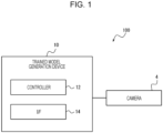
- the trained model generation device 10 includes a controller 12 and an interface (I/F) 14.
- the interface 14 acquires information or data from an external device, and outputs information or data to an external device.
- the interface 14 acquires learning data.
- the interface 14 acquires, as learning data, an image (learning image) obtained by photographing the holding target object 80 (learning target object) by the camera 4 and class information of the holding target object 80.
- the learning image is an image of a learning target object.
- the controller 12 performs learning based on the learning data and generates a trained model used for determining a holding mode for the holding target object 80 in the robot control device 110.
- the controller 12 outputs the generated trained model to the robot control device 110 via the interface 14.
- the controller 12 may include a storage unit.
- the storage unit may include an electromagnetic storage medium such as a magnetic disk, or may include a memory such as a semiconductor memory or a magnetic memory.
- the storage unit stores various pieces of information.
- the storage unit stores a program or the like to be executed by the controller 12.
- the storage unit may be configured as a non-transitory readable medium.
- the storage unit may function as a work memory of the controller 12. At least a part of the storage unit may be configured separately from the controller 12.
- the interface 14 may include a communication device configured to be capable of wired or wireless communication.
- the communication device may be configured to be capable of communication in a communication scheme based on various communication standards.
- the communication device can be configured using a known communication technique.
- the interface 14 may include an output device that outputs information, data, or the like to a user.
- the output device may include, for example, a display device that displays information, data, or the like to a user.
- the display device may include, for example, a liquid crystal display (LCD), an organic electro-luminescence (EL) display, an inorganic EL display, a plasma display panel (PDP), or the like.
- the display device is not limited to these displays, and may include other various types of displays.
- the display device may include a light-emitting device such as a light emission diode (LED) or a laser diode (LD).
- the display device may include other various devices.
- the output device may include, for example, an audio output device such as a speaker that outputs auditory information such as voice.
- the output device may include a vibration device that vibrates to provide tactile information to a user.
- the output device is not limited to these examples, and may include other various devices.
- the interface 14 may be configured to be connectable to an external output device.
- the interface 14 may output information to the external output device so that the external output device outputs the information to a user.
- the interface 14 may be configured to be connectable to a display device 20, which will be described below, as the external output device.
- the robot control device 110 determines a holding mode by using a trained model generated by the trained model generation device 10 and controls the robot 2 such that the robot 2 holds the holding target object 80 in the determined holding mode.
- the robot control device 110 may include at least one processor to provide control and processing capabilities for executing various functions.
- the individual components of the robot control device 110 may include at least one processor. Multiple components among the components of the robot control device 110 may be implemented by one processor.
- the entire robot control device 110 may be implemented by one processor.
- the processor can execute a program for implementing the various functions of the robot control device 110.
- the processor may be configured to be the same as or similar to the processor used in the trained model generation device 10.
- the robot control device 110 may include a storage unit.
- the storage unit may be configured to be the same as or similar to the storage unit used in the trained model generation device 10.
- the class inference model 40 outputs a class inference result as class information.
- the class that can be inferred by the class inference model 40 may be determined based on the shape of the holding target object 80.
- the class that can be inferred by the class inference model 40 may be determined based on various characteristics such as the surface state or the hardness of the holding target object 80.
- the number of classes that can be inferred by the class inference model 40 is four.
- the four classes are referred to as a first class, a second class, a third class, and a fourth class, respectively.
- the number of classes may be three or less or may be five or more.
Landscapes
- Engineering & Computer Science (AREA)
- Robotics (AREA)
- Mechanical Engineering (AREA)
- Automation & Control Theory (AREA)
- General Health & Medical Sciences (AREA)
- Orthopedic Medicine & Surgery (AREA)
- Health & Medical Sciences (AREA)
- Physics & Mathematics (AREA)
- Artificial Intelligence (AREA)
- Evolutionary Computation (AREA)
- Fuzzy Systems (AREA)
- Mathematical Physics (AREA)
- Software Systems (AREA)
- Human Computer Interaction (AREA)
- Image Analysis (AREA)
Abstract
Description
- This application claims priority based on
Japanese Patent Application No. 2021-139421 filed in Japan on August 27, 2021 - The present disclosure relates to a trained model generation method, a trained model generation device, a trained model, and a holding mode inference device.
- A method for appropriately holding an object having a certain shape by a robot hand is known (see, for example, Patent Literature 1).
- Patent Literature 1:
Japanese Unexamined Patent Application Publication No. 2005-169564 - In a trained model generation method according to an embodiment of the present disclosure, a trained model includes a class inference model, a first holding mode inference model, and a second holding mode inference model. The class inference model infers, based on an inference image of a holding target object to be held by a robot, a classification result obtained by classifying the holding target object into a predetermined holding category. The first holding mode inference model infers, based on the classification result and the inference image, a first holding mode for the holding target object. The second holding mode inference model infers, based on the first holding mode and the inference image, a second holding mode for the holding target object. The trained model generation method includes generating the trained model by performing learning using learning data including a learning image of a learning target object corresponding to the holding target object.
- In a trained model generation device according to an embodiment of the present disclosure, a trained model includes a class inference model, a first holding mode inference model, and a second holding mode inference model. The class inference model infers, based on an inference image of a holding target object to be held by a robot, a classification result obtained by classifying the holding target object into a predetermined holding category. The first holding mode inference model infers, based on the classification result and the inference image, a first holding mode for the holding target object. The second holding mode inference model infers, based on the first holding mode and the inference image, a second holding mode for the holding target object. The trained model generation device generates the trained model by performing learning using learning data including a learning image of a learning target object corresponding to the holding target object.
- A trained model according to an embodiment of the present disclosure includes a class inference model, a first holding mode inference model, and a second holding mode inference model. The class inference model infers, based on an inference image of a holding target object to be held by a robot, a classification result obtained by classifying the holding target object into a predetermined holding category. The first holding mode inference model infers, based on the classification result and the inference image, a first holding mode for the holding target object. The second holding mode inference model infers, based on the first holding mode and the inference image, a second holding mode for the holding target object.
- A holding mode inference device according to an embodiment of the present disclosure infers, using a trained model, a mode in which a robot holds a target object. The trained model includes a class inference model, a first holding mode inference model, and a second holding mode inference model. The class inference model infers, based on an inference image of a holding target object to be held by the robot, a classification result obtained by classifying the holding target object into a predetermined holding category. The first holding mode inference model infers, based on the classification result and the inference image, a first holding mode for the holding target object. The second holding mode inference model infers, based on the first holding mode and the inference image, a second holding mode for the holding target object.
-
-
FIG. 1 is a block diagram illustrating an example configuration of a trained model generation device according to an embodiment. -
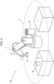
FIG. 2 is a schematic view illustrating an example configuration of a robot control system according to an embodiment. -
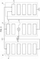
FIG. 3 is a diagram illustrating an example of a model that is being trained. -
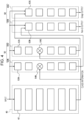
FIG. 4 is a diagram illustrating an example configuration in which a first model and a second model each include a Non-G model and a Grasp model. -
FIG. 5 is a diagram illustrating an example of a holding mode inference model. -
FIG. 6 is a diagram illustrating an example configuration of determining a holding mode by a trained model. -
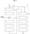
FIG. 7 is a diagram illustrating an example configuration of determining a holding mode by a holding mode inference model. -
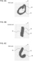
FIG. 8A is a view illustrating an example of a grasping position when a target object is classified into a first class. -
FIG. 8B is a view illustrating an example of a grasping position when a target object is classified into a second class. -
FIG. 8C is a view illustrating an example of a grasping position when a target object is classified into a third class. -
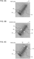
FIG. 9A is a view illustrating an example of a grasping position determined when a target object is classified into a first class. -
FIG. 9B is a view illustrating an example of a grasping position determined when a target object is classified into a second class. -
FIG. 9C is a view illustrating an example of a grasping position determined when a target object is classified into a third class. -
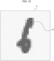
FIG. 10 is a view illustrating an example of a target object image. -
FIG. 11 is a view illustrating an example image of Non-G output and Grasp output of a first model and a second model. - In a trained model that receives an image of an object and outputs a holding mode for the object, there is a demand for increasing the accuracy of inferring the holding mode for the object. A trained model generation method, a trained model generation device, a trained model, and a holding mode inference device according to an embodiment of the present disclosure can increase the accuracy of inferring a holding mode for an object.
- As illustrated in
FIG. 1 andFIG. 2 , arobot control system 100 according to an embodiment of the present disclosure includes arobot 2, arobot control device 110, a trainedmodel generation device 10, and acamera 4. Therobot 2 holds, by anend effector 2B, aholding target object 80 and performs work. Theholding target object 80 is also simply referred to as a target object. Therobot control device 110 controls therobot 2. The trainedmodel generation device 10 generates a trained model to be used to determine a mode in which therobot 2 holds theholding target object 80. The mode in which therobot 2 holds theholding target object 80 is also simply referred to as a holding mode. The holding mode includes a position at which therobot 2 touches theholding target object 80, a force to be applied to theholding target object 80 by therobot 2, or the like. - As illustrated in
FIG. 2 , in the present embodiment, therobot 2 holds theholding target object 80 at awork start point 6. That is, therobot control device 110 controls therobot 2 to hold theholding target object 80 at thework start point 6. Therobot 2 may move theholding target object 80 from thework start point 6 to a work target point 7. Theholding target object 80 is also referred to as a work target. Therobot 2 operates within anoperation range 5. - The
robot 2 includes anarm 2A and theend effector 2B. Thearm 2A may be, for example, a six-axis or seven-axis vertical articulated robot. Thearm 2A may be a three-axis or four-axis horizontal articulated robot or a SCARA robot. The arm 2Amay be a two-axis or three-axis orthogonal robot. Thearm 2A may be a parallel link robot or the like. The number of axes constituting thearm 2A is not limited to that illustrated. In other words, therobot 2 includes thearm 2A connected by multiple joints, and is operated by driving the joints. - The
end effector 2B may include, for example, a grasping hand configured to grasp the holdingtarget object 80. The grasping hand may include multiple fingers. The number of fingers of the grasping hand may be two or more. Each finger of the grasping hand may include one or more joints. Theend effector 2B may include a suction hand configured to suck and hold the holdingtarget object 80. Theend effector 2B may include a scooping hand configured to scoop and hold the holdingtarget object 80. Theend effector 2B is also referred to as a holding portion that holds the holdingtarget object 80. Theend effector 2B is not limited to these examples, and may be configured to perform other various operations. In the configuration illustrated inFIG. 1 , theend effector 2B includes a grasping hand. - The
robot 2 is capable of controlling the position of theend effector 2B by operating thearm 2A. Theend effector 2B may include a shaft serving as reference of a direction in which theend effector 2B acts on the holdingtarget object 80. When theend effector 2B includes a shaft, therobot 2 is capable of controlling the direction of the shaft of theend effector 2B by operating thearm 2A. Therobot 2 controls the start and end of an operation in which theend effector 2B acts on the holdingtarget object 80. Therobot 2 controls the operation of theend effector 2B while controlling the position of theend effector 2B or the direction of the shaft of theend effector 2B, thereby being capable of moving or processing the holdingtarget object 80. In the configuration illustrated inFIG. 1 , therobot 2 causes theend effector 2B to hold the holdingtarget object 80 at thework start point 6, and moves theend effector 2B to the work target point 7. Therobot 2 causes theend effector 2B to release the holdingtarget object 80 at the work target point 7. In this way, therobot 2 is capable of moving the holdingtarget object 80 from thework start point 6 to the work target point 7. - The
robot control system 100 further includes a sensor. The sensor detects physical information of therobot 2. The physical information of therobot 2 may include information regarding the actual positions or postures of individual components of therobot 2 or the speeds or accelerations of the individual components of therobot 2. The physical information of therobot 2 may include information regarding forces that act on the individual components of therobot 2. The physical information of therobot 2 may include information regarding a current that flows through a motor that drives the individual components of therobot 2 or a torque of the motor. The physical information of therobot 2 represents a result of an actual operation of therobot 2. That is, therobot control system 100 acquires the physical information of therobot 2 and thereby being capable of grasping a result of an actual operation of therobot 2. - The sensor may include a force sensor or a tactile sensor that detects, as physical information of the
robot 2, a force, a distributed pressure, a slip, or the like acting on therobot 2. The sensor may include a motion sensor that detects, as the physical information of therobot 2, the position or posture of therobot 2 or the speed or acceleration of therobot 2. The sensor may include a current sensor that detects, as the physical information of therobot 2, a current flowing through a motor that drives therobot 2. The sensor may include a torque sensor that detects, as the physical information of therobot 2, a torque of a motor that drives therobot 2. - The sensor may be installed at a joint of the
robot 2 or a joint driving unit that drives the j oint. The sensor may be installed at thearm 2A or theend effector 2B of therobot 2. - The sensor outputs detected physical information of the
robot 2 to therobot control device 110. The sensor detects and outputs the physical information of therobot 2 at a predetermined timing. The sensor outputs the physical information of therobot 2 as time-series data. - In the example configuration illustrated in
FIG. 1 , therobot control system 100 includes thecamera 4 attached to theend effector 2B of therobot 2. For example, thecamera 4 may photograph the holdingtarget object 80 in a direction from theend effector 2B toward the holdingtarget object 80. That is, thecamera 4 photographs the holdingtarget object 80 in a direction in which theend effector 2B holds the holdingtarget object 80. An image captured by photographing the holdingtarget object 80 in the direction in which theend effector 2B holds the holdingtarget object 80 is also referred to as a holding target image (inference image). The inference image is an image for inferring a holding target and includes the holdingtarget object 80. Thecamera 4 may include a depth sensor and may be configured to be capable of acquiring depth data of the holdingtarget object 80. The depth data is data regarding distances in individual directions within the range of the angle of view of the depth sensor. More specifically, the depth data is information regarding the distance from thecamera 4 to a measurement point. The image captured by thecamera 4 may include monochrome brightness information or color brightness information represented by red, green, and blue (RGB) or the like. The number ofcameras 4 is not limited to one, and may be two or more. - The
camera 4 is not limited to the configuration of being attached to theend effector 2B, and may be provided at any position at which thecamera 4 is capable of photographing the holdingtarget object 80. In a configuration in which thecamera 4 is attached to a structure other than theend effector 2B, the above-described holding target image may be generated based on an image captured by thecamera 4 attached to the structure. The holding target image may be generated by performing image conversion based on the relative position and relative posture of theend effector 2B with respect to the attachment position and attachment posture of thecamera 4. Alternatively, the holding target image may be generated using computer-aided design (CAD) and drawing data. - As illustrated in
FIG. 1 , the trainedmodel generation device 10 includes acontroller 12 and an interface (I/F) 14. Theinterface 14 acquires information or data from an external device, and outputs information or data to an external device. Theinterface 14 acquires learning data. Theinterface 14 acquires, as learning data, an image (learning image) obtained by photographing the holding target object 80 (learning target object) by thecamera 4 and class information of the holdingtarget object 80. The learning image is an image of a learning target object. Thecontroller 12 performs learning based on the learning data and generates a trained model used for determining a holding mode for the holdingtarget object 80 in therobot control device 110. Thecontroller 12 outputs the generated trained model to therobot control device 110 via theinterface 14. - The
controller 12 may include at least one processor to provide control and processing capabilities for executing various functions. The processor may execute a program for implementing the various functions of thecontroller 12. The processor may be implemented as a single integrated circuit. The integrated circuit is also referred to as an IC. The processor may be implemented as multiple communicably connected integrated circuits and discrete circuits. The processor may be implemented based on other various known techniques. - The
controller 12 may include a storage unit. The storage unit may include an electromagnetic storage medium such as a magnetic disk, or may include a memory such as a semiconductor memory or a magnetic memory. The storage unit stores various pieces of information. The storage unit stores a program or the like to be executed by thecontroller 12. The storage unit may be configured as a non-transitory readable medium. The storage unit may function as a work memory of thecontroller 12. At least a part of the storage unit may be configured separately from thecontroller 12. - The
interface 14 may include a communication device configured to be capable of wired or wireless communication. The communication device may be configured to be capable of communication in a communication scheme based on various communication standards. The communication device can be configured using a known communication technique. - The
interface 14 may include an input device that receives an input of information, data, or the like from a user. The input device may include, for example, a touch panel or a touch sensor, or a pointing device such as a mouse. The input device may include a physical key. The input device may include an audio input device such as a microphone. Theinterface 14 may be configured to be connectable to an external input device. Theinterface 14 may be configured to acquire information input to the external input device from the external input device. - The
interface 14 may include an output device that outputs information, data, or the like to a user. The output device may include, for example, a display device that displays information, data, or the like to a user. The display device may include, for example, a liquid crystal display (LCD), an organic electro-luminescence (EL) display, an inorganic EL display, a plasma display panel (PDP), or the like. The display device is not limited to these displays, and may include other various types of displays. The display device may include a light-emitting device such as a light emission diode (LED) or a laser diode (LD). The display device may include other various devices. The output device may include, for example, an audio output device such as a speaker that outputs auditory information such as voice. The output device may include a vibration device that vibrates to provide tactile information to a user. The output device is not limited to these examples, and may include other various devices. Theinterface 14 may be configured to be connectable to an external output device. Theinterface 14 may output information to the external output device so that the external output device outputs the information to a user. Theinterface 14 may be configured to be connectable to a display device 20, which will be described below, as the external output device. - The
robot control device 110 determines a holding mode by using a trained model generated by the trainedmodel generation device 10 and controls therobot 2 such that therobot 2 holds the holdingtarget object 80 in the determined holding mode. - The
robot control device 110 may include at least one processor to provide control and processing capabilities for executing various functions. The individual components of therobot control device 110 may include at least one processor. Multiple components among the components of therobot control device 110 may be implemented by one processor. The entirerobot control device 110 may be implemented by one processor. The processor can execute a program for implementing the various functions of therobot control device 110. The processor may be configured to be the same as or similar to the processor used in the trainedmodel generation device 10. - The
robot control device 110 may include a storage unit. The storage unit may be configured to be the same as or similar to the storage unit used in the trainedmodel generation device 10. - The
controller 12 of the trainedmodel generation device 10 performs learning by using, as learning data, an image captured by photographing the holdingtarget object 80 or an image generated from CAD data or the like of the holdingtarget object 80 and class information of the holdingtarget object 80, and generates a trained model for inferring a holding mode for the holdingtarget object 80. The learning data may include teacher data used in so-called supervised learning. The learning data may include data that is used in so-called unsupervised learning and that is generated by a device that performs learning. An image captured by photographing the holdingtarget object 80 or an image generated as an image of the holdingtarget object 80 is collectively referred to as a target object image. As illustrated inFIG. 3 , the model includes aclass inference model 40, a first holdingmode inference model 50, and a second holdingmode inference model 60. Thecontroller 12 updates the model being trained by learning using a target object image as learning data, and generates a trained model. - The
class inference model 40 receives a target object image as an input. Theclass inference model 40 infers a holding category into which the holdingtarget object 80 included in the input target object image is to be classified. That is, theclass inference model 40 classifies the target object into any one of multiple inferable holding categories. The multiple holding categories that can be inferred by theclass inference model 40 are categories outputtable by theclass inference model 40. A holding category is a category indicating a difference in the shape of the holdingtarget object 80, and is also referred to as a class. - The
class inference model 40 classifies the holdingtarget object 80 included in the input holding target image into a predetermined class. Theclass inference model 40 outputs, based on the target object image, a classification result obtained by classifying the holdingtarget object 80 into a predetermined class. In other words, theclass inference model 40 infers, based on the input target object image, a class to which the holdingtarget object 80 belongs when the holdingtarget object 80 is classified into a class. - The
class inference model 40 outputs a class inference result as class information. The class that can be inferred by theclass inference model 40 may be determined based on the shape of the holdingtarget object 80. The class that can be inferred by theclass inference model 40 may be determined based on various characteristics such as the surface state or the hardness of the holdingtarget object 80. In the present embodiment, the number of classes that can be inferred by theclass inference model 40 is four. The four classes are referred to as a first class, a second class, a third class, and a fourth class, respectively. The number of classes may be three or less or may be five or more. - The first holding
mode inference model 50 receives, as an input, a target object image and class information output by theclass inference model 40. The first holdingmode inference model 50 infers, based on the received target object image and class information, a holding mode (first holding mode) for the holdingtarget object 80, and outputs a holding mode inference result. - The second holding
mode inference model 60 receives, as an input, a target object image and the inference result output by the first holdingmode inference model 50. The second holdingmode inference model 60 infers, based on the received target object image and inference result of the first holdingmode inference model 50, a holding mode (second holding mode) for the holdingtarget object 80, and outputs a holding mode inference result. - The
class inference model 40, the first holdingmode inference model 50, and the second holdingmode inference model 60 may each be configured as, for example, a convolution neural network (CNN) including multiple layers. The layers of theclass inference model 40 are represented as processing layers 42. The layers of the first holdingmode inference model 50 are represented as processing layers 52. The layers of the second holdingmode inference model 60 are represented as processing layers 62. Information input to theclass inference model 40, the first holdingmode inference model 50, and the second holdingmode inference model 60 is subjected to convolution processing based on a predetermined weighting coefficient in each layer of the CNN. In the learning of theclass inference model 40, the first holdingmode inference model 50, and the second holdingmode inference model 60, the weighting coefficient is updated. Theclass inference model 40, the first holdingmode inference model 50, and the second holdingmode inference model 60 may be constituted by VGG16 or ResNet50. Theclass inference model 40, the first holdingmode inference model 50, and the second holdingmode inference model 60 are not limited to these examples, and may be configured as other various models. - The first holding
mode inference model 50 includes amultiplier 54 that receives an input of class information. Themultiplier 54 multiplies the output of theprocessing layer 52 in the preceding stage by a weighting coefficient based on the class information and outputs a result to theprocessing layer 52 in the subsequent stage. - As illustrated in
FIG. 4 , the first holdingmode inference model 50 may include a firstNon-G model 50N and afirst Grasp model 50G. The firstNon-G model 50N includesprocessing layers 52N and amultiplier 54N. Thefirst Grasp model 50G includesprocessing layers 52G and amultiplier 54G. The second holdingmode inference model 60 may include a secondNon-G model 60N and asecond Grasp model 60G. The secondNon-G model 60N includes processing layers 62N. Thesecond Grasp model 60G includes processing layers 62G. - The
first Grasp model 50G and thesecond Grasp model 60G output an inference result of a holding mode in the mode of a Grasp output. The Grasp output corresponds to the output of the first holdingmode inference model 50 and the second holdingmode inference model 60. The Grasp output is assumed to be information indicating an inference result of a holding mode for the holdingtarget object 80. The Grasp output may be, for example, information indicating a position to be touched when the holdingtarget object 80 is held. The Grasp output may be represented by an image, for example. - The first
Non-G model 50N and the secondNon-G model 60N output an inference result of a holding mode in the mode of a Non-G output. The Non-G output is assumed to be information for explaining a reason why the inference result of a holding position 82 (seeFIG. 8A, FIG. 8B, FIG. 8C , and so forth) of the holdingtarget object 80 is derived. The Non-G output may be, for example, information indicating a position not to be touched when the holdingtarget object 80 is held. The Non-G output may be represented by an image, for example. The firstNon-G model 50N or the secondNon-G model 60N is also referred to as a third holding mode inference model. - As described above, in the first holding
mode inference model 50, themultiplier 54 multiplies, based on class information, the output of theprocessing layer 52 by a weighting coefficient. In the firstNon-G model 50N and thefirst Grasp model 50G, themultipliers mode inference model 50, the firstNon-G model 50N, or thefirst Grasp model 50G branches an input target object image to the processing layers 52, 52N, or 52G corresponding to the four classes, as illustrated inFIG. 5 . Themultiplier first multiplier 541, asecond multiplier 542, athird multiplier 543, and afourth multiplier 544 corresponding to the four classes, respectively. Thefirst multiplier 541, thesecond multiplier 542, thethird multiplier 543, and thefourth multiplier 544 each multiply the output of theprocessing layer mode inference model 50, the firstNon-G model 50N, and thefirst Grasp model 50G each include anadder 56 that adds outputs of thefirst multiplier 541, thesecond multiplier 542, thethird multiplier 543, and thefourth multiplier 544. The output of theadder 56 is input to theprocessing layer mode inference model 50, the firstNon-G model 50N, and thefirst Grasp model 50G each output, as a holding mode inference result, the output of theprocessing layer adder 56. - The weighting coefficient by which each of the
first multiplier 541, thesecond multiplier 542, thethird multiplier 543, and thefourth multiplier 544 multiplies the output of theprocessing layer multiplier target object 80 has been classified into. It is assumed that, when the holdingtarget object 80 is classified into the first class, the weighting coefficient of thefirst multiplier 541 is set to 1, and the weighting coefficients of thesecond multiplier 542, thethird multiplier 543, and thefourth multiplier 544 are set to 0. In this case, the output of theprocessing layer adder 56. - The class information output by the
class inference model 40 may represent a probability that the holdingtarget object 80 is classified into each of the four classes. For example, probabilities that the holdingtarget object 80 is classified into the first class, the second class, the third class, and the fourth class may be represented by X1, X2, X3, and X4, respectively. In this case, theadder 56 adds an output obtained by multiplying the output of theprocessing layer processing layer processing layer processing layer - The
controller 12 performs learning by using a target object image and class information of the holdingtarget object 80 as learning data, thereby generating theclass inference model 40, the first holdingmode inference model 50, and the second holdingmode inference model 60 as a trained model. The class information of the holdingtarget object 80 is given as learning data to theclass inference model 40. - The
controller 12 requires correct answer data to generate the trained model. For example, to generate theclass inference model 40, thecontroller 12 requires learning data associated with information indicating a correct answer about a class into which an image used as learning data is classified. In addition, to generate the first holdingmode inference model 50 and the second holdingmode inference model 60, thecontroller 12 requires learning data associated with information indicating a correct answer about a grasping position of a target object appearing in an image used as learning data. - The trained model used in the
robot control system 1 according to the present embodiment may include a model that has learned the class or the grasping position of the holdingtarget object 80 in a target object image through learning, or may include a model that has not learned the class or the grasping position of the holdingtarget object 80. Even when the trained model has not learned the class or the grasping position of the holdingtarget object 80, thecontroller 12 may infer the class and the grasping position of the holdingtarget object 80 by using a trained model trained based on the class and the grasping position of a learning target object corresponding to the holdingtarget object 80, which is a learning target object having a shape, dimension, or the like similar to that of the holdingtarget object 80, for example. Thus, in therobot control system 1 according to the present embodiment, thecontroller 12 may or may not learn the holdingtarget object 80 itself to generate a trained model. - The
robot control device 110 determines, based on a trained model, a holding mode for the holdingtarget object 80. The trained model is configured to receive, as an input, an image captured by photographing the holdingtarget object 80, and output an inference result of a holding mode for the holdingtarget object 80. Therobot control device 110 acquires an image captured by photographing the holdingtarget object 80 from thecamera 4, inputs the image to the trained model, and acquires an inference result of a holding mode for the holdingtarget object 80 from the trained model. Therobot control device 110 determines a holding mode based on the inference result of the holding mode for the holdingtarget object 80, and controls therobot 2 such that therobot 2 holds the holdingtarget object 80 in the determined holding mode. - As illustrated in
FIG. 6 , therobot control device 110 configures a trained model such that the class information from theclass inference model 40 is input to the first holdingmode inference model 50. Therobot control device 110 configures a trained model such that the output of the first holdingmode inference model 50 is input to the second holdingmode inference model 60. - The
robot control device 110 inputs a target object image to theclass inference model 40 and causes theclass inference model 40 to output class information. Therobot control device 110 inputs the target object image to the first holdingmode inference model 50, inputs the class information from theclass inference model 40 to the first holdingmode inference model 50, and causes the first holdingmode inference model 50 to output an inference result of a holding mode for the holdingtarget object 80. Therobot control device 110 inputs, to the second holdingmode inference model 60, the target object image and the inference result of the holding mode obtained by the first holdingmode inference model 50, and causes the second holdingmode inference model 60 to output an inference result of a holding mode for the holdingtarget object 80. Based on the inference result of the holding mode obtained by the second holdingmode inference model 60, therobot control device 110 determines a holding mode for the holdingtarget object 80. - The class information output from the
class inference model 40 indicates the class to which the holdingtarget object 80 is classified among the first to fourth classes based on the input target object image. Specifically, it is assumed that theclass inference model 40 is configured to output "1000" as the class information when the holding category (class) into which the holdingtarget object 80 is to be classified is inferred as the first class. It is assumed that theclass inference model 40 is configured to output "0100" as the class information when the holding category (class) into which the holdingtarget object 80 is to be classified is inferred as the second class. It is assumed that theclass inference model 40 is configured to output "0010" as the class information when the holding category (class) into which the holdingtarget object 80 is to be classified is inferred as the third class. It is assumed that theclass inference model 40 is configured to output "0001" as the class information when the holding category (class) into which the holdingtarget object 80 is to be classified is inferred as the fourth class. - As illustrated in
FIG. 7 , therobot control device 110 may apply only the first holdingmode inference model 50 and the second holdingmode inference model 60 as a trained model and directly input the class information to the first holdingmode inference model 50. - In the present embodiment, it is assumed that
shape images 81 each representing the shape of the holdingtarget object 80 illustrated inFIG. 8A, FIG. 8B, and FIG. 8C are input as target object images to the trained model. In this case, it is assumed that theshape image 81 is classified into a class based on the shape of the holdingtarget object 80. It is assumed that, when the holdingtarget object 80 has an O-shape, theshape image 81 is classified into the first class. It is assumed that, when the holdingtarget object 80 has an I-shape, theshape image 81 is classified into the second class. It is assumed that, when the holdingtarget object 80 has a J-shape, theshape image 81 is classified into the third class. The J-shape can also be regarded as a shape obtained by combining an I-shape and an O-shape. It is assumed that, when the holdingtarget object 80 has another shape, theshape image 81 is classified into the fourth class. - In response to inferring that the
shape image 81 is classified into the first class, theclass inference model 40 outputs " 1000" as class information. In response to acquiring "1000" as class information, the first holdingmode inference model 50 infers, as a holdingposition 82, an inner side of the O-shapedholding target object 80 in theshape image 81. In response to inferring that theshape image 81 is classified into the second class, theclass inference model 40 outputs "0100" as class information. In response to acquiring "0100" as class information, the first holdingmode inference model 50 infers, as holdingpositions 82, positions on both sides of the I-shape near the center of the I-shape in theshape image 81. In response to inferring that theshape image 81 is classified into the third class, theclass inference model 40 outputs "0010" as class information. In response to acquiring "0010" as class information, the first holdingmode inference model 50 infers, as holdingpositions 82, positions on both sides of the J-shape near an end of the J-shape in theshape image 81. In other words, the first holdingmode inference model 50 infers, as the holdingpositions 82, positions on both sides of the I-shape near an end of the I-shape far from the O-shape in the shape obtained by combining the I-shape and the O-shape. - A description will be given of an example in which the
robot control device 110 infers the holding position(s) 82 when the holdingtarget object 80 is a screw. As illustrated inFIG. 9A, FIG. 9B, and FIG. 9C , therobot control device 110 inputs, as a target object image, an image of the holdingtarget object 80 which is a screw to the trained model. The screw includes ascrew head 83 and ascrew shaft 84. When theshape image 81 of the screw is classified into the first class, the trained model is incapable of specifying the position corresponding to the inner side of the screw and is incapable of inferring the holdingposition 82. Thus, no holdingposition 82 is indicated in theshape image 81 classified into the first class. When theshape image 81 of the screw is classified into the second class, the trained model infers, as the holdingpositions 82, both sides of thescrew shaft 84 near the center of thescrew shaft 84. When theshape image 81 of the screw is classified into the third class, the trained model infers, as the holdingpositions 82, the positions of both sides of thescrew shaft 84 near an end of thescrew shaft 84 far from thescrew head 83. - As described above, the trained
model generation device 10 according to the present embodiment is capable of generating a trained model including theclass inference model 40, the first holdingmode inference model 50, and the second holdingmode inference model 60. The first holdingmode inference model 50 infers a holding mode, based on class information. The second holdingmode inference model 60 infers a holding mode, not based on class information. Accordingly, therobot control device 110 is capable of determining a holding mode by complementing an inference result based on class information and an inference result not based on class information with each other. As a result, the accuracy of inferring a holding mode for the holdingtarget object 80 can be increased. - The trained
model generation device 10 may execute a trained model generation method including a procedure of generating, through learning, a trained model including theclass inference model 40, the first holdingmode inference model 50, and the second holdingmode inference model 60. - The
robot control device 110 may infer a holding mode by using the trained model. Therobot control device 110 is also referred to as a holding mode inference device. - Other embodiments will be described below.
- In the above embodiment, the configuration in which a trained model infers the holding position(s) 82 as a holding mode has been described. The trained model is capable of inferring not only the holding position(s) 82 but also another mode as the holding mode.
- For example, the trained model may infer, as the holding mode, a force to be applied by the
robot 2 to hold the holdingtarget object 80. In this case, the first holdingmode inference model 50 and the second holdingmode inference model 60 infer and output a force to be applied to hold the holdingtarget object 80. - For example, the trained model may infer, as the holding mode, the type of a hand by which the
robot 2 holds the holdingtarget object 80. In this case, the first holdingmode inference model 50 and the second holdingmode inference model 60 infer and output the type of a hand used to hold the holdingtarget object 80. - It is assumed that the
shape image 81 illustrated inFIG. 10 is input as a target object image to the trained model. In this case, the trained model outputs information illustrated as an image in the table inFIG. 11 , for example. In the table inFIG. 11 , information output by the first holdingmode inference model 50 is described in the row denoted by "first model". Information output by the second holdingmode inference model 60 is described in the row denoted by "second model". Information of Non-G output is described in the column denoted by "Non-G". Information of Grasp output is described in the column denoted by "Grasp". - The information described in the cell located in the row of "first model" and the column of "Non-G" corresponds to the Non-G output that is output by the first
Non-G model 50N included in the first holdingmode inference model 50. The information described in the cell located in the row of "second model" and the column of "Non-G" corresponds to the Non-G output that is output by the secondNon-G model 60N included in the second holdingmode inference model 60. It is assumed that the Non-G output indicates that a portion in a color closer to black is not to be touched when held, and a portion in a color closer to white is to be touched when held. The meaning of the color of the Non-G output is not limited thereto. The Non-G output is not limited to an image and may be represented by numerical information. - The information described in the cell located in the row of "first model" and the column of "Grasp" corresponds to the Grasp output that is output by the
first Grasp model 50G included in the first holdingmode inference model 50. The information described in the cell located in the row of "second model" and the column of "Grasp" corresponds to the Grasp output that is output by thesecond Grasp model 60G included in the second holdingmode inference model 60. InFIG. 11 , the shape of the holdingtarget object 80 is indicated by an imaginary line of a two-dot chain line in the Grasp output. The holding positions 82 are indicated by solid-line circles. It is assumed that the Grasp output indicates that a portion in a color closer to black is more appropriate as the holdingposition 82, and a portion in a color closer to white is more inappropriate as the holdingposition 82. The meaning of the color of the Grasp output is not limited thereto. The Grasp output is not limited to an image and may be represented by numerical information. - An embodiment of the trained
model generation device 10 and therobot control system 100 has been described above. The embodiment of the present disclosure can include an embodiment of, in addition to a method or a program for implementing the system or the device, a storage medium (for example, an optical disc, a magneto-optical disk, a CD-ROM, a CD-R, a CD-RW, a magnetic tape, a hard disk, or a memory card) storing the program. - The implementation form of the program is not limited to an application program such as an object code compiled by a compiler or a program code executed by an interpreter, and may be a form such as a program module incorporated in an operating system. The program may or may not be configured such that all processing is performed only in a CPU on a control board. The program may be configured such that a part or the entirety of the program is executed by another processing unit mounted on an expansion board or an expansion unit added to the board as necessary.
- The embodiment according to the present disclosure has been described based on the drawings and examples. Note that a person skilled in the art could make various variations or changes based on the present disclosure. Thus, note that the variations or changes are included in the scope of the present disclosure. For example, the functions or the like included in the individual components or the like can be reconfigured without logical inconsistency. Multiple components or the like can be combined into one component or can be divided.
- All the structural elements described in the present disclosure and/or all of the disclosed methods or all the steps of a process may be combined in any combination except for combinations in which these features are mutually exclusive. Each of the features described in the present disclosure may be replaced with an alternative feature serving for an identical, equivalent, or similar purpose, unless explicitly denied. Thus, unless explicitly denied, each of the disclosed features is merely one example of a comprehensive series of identical or equivalent features.
- Furthermore, the embodiment according to the present disclosure is not limited to any specific configuration of the above-described embodiment. The embodiment according to the present disclosure may be extended to all novel features described in the present disclosure, or any combination thereof, or all novel methods described, or processing steps, or any combination thereof.
- In the present disclosure, descriptions such as "first" and "second" are identifiers for distinguishing corresponding elements from each other. In the present disclosure, the elements distinguished by "first", "second", and the like may have ordinal numbers exchanged with each other. For example, "first" and "second" serving as identifiers may be exchanged between the first class and the second class. The exchange of the identifiers is performed simultaneously. Even after the exchange of the identifiers, the elements are distinguished from each other. The identifiers may be deleted. The elements whose identifiers have been deleted are distinguished from each other by reference signs. The identifiers such as "first" and "second" in the present disclosure alone are not to be used as a basis for interpreting the order of corresponding elements or the existence of identifiers with smaller numbers.
-
- 10 trained model generation device (12: controller, 14: interface)
- 20 display device
- 40 class inference model (42: processing layer)
- 50 first holding mode inference model (52: processing layer, 54: multiplier (541 to 544: first to fourth multipliers), 56: adder)
- 50N first Non-G model (52N: processing layer, 54N: multiplier)
- 50G first Grasp model (52G: processing layer, 54G: multiplier)
- 60 second holding mode inference model (62: processing layer)
- 60N second Non-G model (62N: processing layer)
- 60G second Grasp model (62G: processing layer)
- 80 holding target object (83: screw head, 84: screw shaft)
- 81 shape image
- 82 holding position
- 100 robot control system (2: robot, 2A: arm, 2B: end effector, 3: sensor, 4: camera, 5: robot influence range, 6: work start point, 7: work target point, 110: robot control device)
Claims (7)
- A trained model generation method comprising:
generating a trained model by performing learning using learning data comprising a learning image of a learning target object corresponding to a holding target object to be held by a robot, the trained model comprising:a class inference model configured to infer, based on an inference image of the holding target object, a classification result obtained by classifying the holding target object into a predetermined holding category;a first holding mode inference model configured to infer, based on the classification result and the inference image, a first holding mode for the holding target object; anda second holding mode inference model configured to infer, based on the first holding mode and the inference image, a second holding mode for the holding target object. - The trained model generation method according to claim 1, wherein the learning data further comprises information regarding a class into which the target object is classified.
- The trained model generation method according to claim 1 or 2, whereinthe trained model comprises a third holding mode inference model configured to infer, based on the classification result received from the class inference model and an image of the target object, a mode in which the robot is not to hold the target object, andthe second holding mode inference model is configured to infer, further based on an inference result of the third holding mode inference model, a mode in which the robot holds the target object and output the inferred mode.
- The trained model generation method according to claim 3, whereinthe first holding mode inference model is configured to output a position to be touched when the target object is held, andthe third holding mode inference model is configured to output a position not to be touched when the target object is held.
- A trained model generation device configured to generate a trained model by performing learning using learning data comprising a learning image of a learning target object corresponding to a holding target object to be held by a robot, the trained model comprising:a class inference model configured to infer, based on an inference image of the holding target object, a classification result obtained by classifying the holding target object into a predetermined holding category;a first holding mode inference model configured to infer, based on the classification result and the inference image, a first holding mode for the holding target object; anda second holding mode inference model configured to infer, based on the first holding mode and the inference image, a second holding mode for the holding target obj ect.
- A trained model comprising:a class inference model configured to infer, based on an inference image of a holding target object to be held by a robot, a classification result obtained by classifying the holding target object into a predetermined holding category;a first holding mode inference model configured to infer, based on the classification result and the inference image, a first holding mode for the holding target object; anda second holding mode inference model configured to infer, based on the first holding mode and the inference image, a second holding mode for the holding target obj ect.
- A holding mode inference device configured to infer, using a trained model, a mode in which a robot holds a target object, the trained model comprising:a class inference model configured to infer, based on an inference image of a holding target object to be held by the robot, a classification result obtained by classifying the holding target object into a predetermined holding category;a first holding mode inference model configured to infer, based on the classification result and the inference image, a first holding mode for the holding target object; anda second holding mode inference model configured to infer, based on the first holding mode and the inference image, a second holding mode for the holding target obj ect.
Applications Claiming Priority (2)
| Application Number | Priority Date | Filing Date | Title |
|---|---|---|---|
| JP2021139421 | 2021-08-27 | ||
| PCT/JP2022/032290 WO2023027187A1 (en) | 2021-08-27 | 2022-08-26 | Trained model generation method, trained model generation device, trained model, and device for estimating maintenance state |
Publications (2)
| Publication Number | Publication Date |
|---|---|
| EP4393660A1 true EP4393660A1 (en) | 2024-07-03 |
| EP4393660A4 EP4393660A4 (en) | 2025-08-20 |
Family
ID=85321677
Family Applications (1)
| Application Number | Title | Priority Date | Filing Date |
|---|---|---|---|
| EP22861475.6A Pending EP4393660A4 (en) | 2021-08-27 | 2022-08-26 | Method for generating trained models, device for generating trained models, trained model and device for estimating the maintenance status |
Country Status (5)
| Country | Link |
|---|---|
| US (1) | US20240351198A1 (en) |
| EP (1) | EP4393660A4 (en) |
| JP (1) | JP7717169B2 (en) |
| CN (1) | CN117836101A (en) |
| WO (1) | WO2023027187A1 (en) |
Family Cites Families (8)
| Publication number | Priority date | Publication date | Assignee | Title |
|---|---|---|---|---|
| JP4001105B2 (en) | 2003-12-11 | 2007-10-31 | トヨタ自動車株式会社 | Grasping method of arbitrarily shaped object by robot |
| CN110785268B (en) * | 2017-06-28 | 2023-04-04 | 谷歌有限责任公司 | Machine learning method and device for semantic robot grabbing |
| US11097418B2 (en) * | 2018-01-04 | 2021-08-24 | X Development Llc | Grasping of an object by a robot based on grasp strategy determined using machine learning model(s) |
| JP7171294B2 (en) * | 2018-07-31 | 2022-11-15 | キヤノン株式会社 | Information processing device, information processing method and program |
| JP7377627B2 (en) * | 2019-06-04 | 2023-11-10 | グローリー株式会社 | Object detection device, object grasping system, object detection method, and object detection program |
| JP2021070122A (en) * | 2019-10-31 | 2021-05-06 | ミネベアミツミ株式会社 | Learning data generation method |
| JP7479756B2 (en) | 2020-03-04 | 2024-05-09 | ダイハツ工業株式会社 | transmission |
| JP2021003805A (en) * | 2020-10-07 | 2021-01-14 | 株式会社東芝 | Object handling device, and control method |
-
2022
- 2022-08-26 JP JP2023544012A patent/JP7717169B2/en active Active
- 2022-08-26 US US18/686,363 patent/US20240351198A1/en active Pending
- 2022-08-26 CN CN202280057447.5A patent/CN117836101A/en active Pending
- 2022-08-26 EP EP22861475.6A patent/EP4393660A4/en active Pending
- 2022-08-26 WO PCT/JP2022/032290 patent/WO2023027187A1/en not_active Ceased
Also Published As
| Publication number | Publication date |
|---|---|
| WO2023027187A1 (en) | 2023-03-02 |
| CN117836101A (en) | 2024-04-05 |
| JP7717169B2 (en) | 2025-08-01 |
| JPWO2023027187A1 (en) | 2023-03-02 |
| EP4393660A4 (en) | 2025-08-20 |
| US20240351198A1 (en) | 2024-10-24 |
Similar Documents
| Publication | Publication Date | Title |
|---|---|---|
| CN114206558B (en) | Efficient robot control based on input from remote client devices | |
| CN117103277B (en) | A robotic arm perception method based on multimodal data fusion | |
| JP2023542055A (en) | Interactive tactile perception method for object instance classification and recognition | |
| JP2025147230A (en) | Robot holding mode determination device, holding mode determination method, and robot control system | |
| CN116472551A (en) | Device for adjusting parameters, robot system, method and computer program | |
| CN117794709A (en) | Gripping parameter estimation device and gripping parameter estimation method | |
| WO2022085699A1 (en) | System control device, robot control method, terminal device, terminal control method, and robot control system | |
| EP4393660A1 (en) | Trained model generation method, trained model generation device, trained model, and device for estimating maintenance state | |
| JP7482719B2 (en) | ROBOT CONTROL DEVICE, ROBOT CONTROL SYSTEM, AND ROBOT CONTROL METHOD | |
| JP7651691B2 (en) | Holding position determining device and holding position determining method | |
| US20240383151A1 (en) | Estimation device, estimation method, and control device | |
| US20240265691A1 (en) | Trained model generating device, trained model generating method, and recognition device | |
| KR20240081551A (en) | System and method for acquisition dataset of robot control | |
| US20250351247A1 (en) | Data obtaining device, data obtaining method, and data obtaining stage | |
| US20240265669A1 (en) | Trained model generating device, trained model generating method, and recognition device | |
| US20260011124A1 (en) | Data obtaining device, data obtaining method, and data obtaining stage | |
| WO2023171687A1 (en) | Robot control device and robot control method | |
| WO2024253174A1 (en) | Teaching data generation device, robot controller, robot control system, and teaching data generation method | |
| WO2025013784A1 (en) | Processing device, program, display device, and processing system |
Legal Events
| Date | Code | Title | Description |
|---|---|---|---|
| STAA | Information on the status of an ep patent application or granted ep patent |
Free format text: STATUS: THE INTERNATIONAL PUBLICATION HAS BEEN MADE |
|
| PUAI | Public reference made under article 153(3) epc to a published international application that has entered the european phase |
Free format text: ORIGINAL CODE: 0009012 |
|
| STAA | Information on the status of an ep patent application or granted ep patent |
Free format text: STATUS: REQUEST FOR EXAMINATION WAS MADE |
|
| 17P | Request for examination filed |
Effective date: 20240229 |
|
| AK | Designated contracting states |
Kind code of ref document: A1 Designated state(s): AL AT BE BG CH CY CZ DE DK EE ES FI FR GB GR HR HU IE IS IT LI LT LU LV MC MK MT NL NO PL PT RO RS SE SI SK SM TR |
|
| DAV | Request for validation of the european patent (deleted) | ||
| DAX | Request for extension of the european patent (deleted) | ||
| REG | Reference to a national code |
Ref country code: DE Ref legal event code: R079 Free format text: PREVIOUS MAIN CLASS: B25J0013080000 Ipc: B25J0009160000 |
|
| A4 | Supplementary search report drawn up and despatched |
Effective date: 20250718 |
|
| RIC1 | Information provided on ipc code assigned before grant |
Ipc: B25J 9/16 20060101AFI20250714BHEP Ipc: B25J 13/08 20060101ALI20250714BHEP Ipc: G05B 19/4155 20060101ALI20250714BHEP |