EP4393654A1 - Motion control method for under-actuated system robot, and under-actuated system robot - Google Patents
Motion control method for under-actuated system robot, and under-actuated system robot Download PDFInfo
- Publication number
- EP4393654A1 EP4393654A1 EP22918276.1A EP22918276A EP4393654A1 EP 4393654 A1 EP4393654 A1 EP 4393654A1 EP 22918276 A EP22918276 A EP 22918276A EP 4393654 A1 EP4393654 A1 EP 4393654A1
- Authority
- EP
- European Patent Office
- Prior art keywords
- base portion
- loaded object
- robot
- status information
- information
- Prior art date
- Legal status (The legal status is an assumption and is not a legal conclusion. Google has not performed a legal analysis and makes no representation as to the accuracy of the status listed.)
- Pending
Links
Images








Classifications
-
- B—PERFORMING OPERATIONS; TRANSPORTING
- B25—HAND TOOLS; PORTABLE POWER-DRIVEN TOOLS; MANIPULATORS
- B25J—MANIPULATORS; CHAMBERS PROVIDED WITH MANIPULATION DEVICES
- B25J9/00—Program-controlled manipulators
- B25J9/16—Program controls
- B25J9/1656—Program controls characterised by programming, planning systems for manipulators
- B25J9/1664—Program controls characterised by programming, planning systems for manipulators characterised by motion, path, trajectory planning
-
- B—PERFORMING OPERATIONS; TRANSPORTING
- B62—LAND VEHICLES FOR TRAVELLING OTHERWISE THAN ON RAILS
- B62D—MOTOR VEHICLES; TRAILERS
- B62D57/00—Vehicles characterised by having other propulsion or other ground- engaging means than wheels or endless track, alone or in addition to wheels or endless track
- B62D57/02—Vehicles characterised by having other propulsion or other ground- engaging means than wheels or endless track, alone or in addition to wheels or endless track with ground-engaging propulsion means, e.g. walking members
- B62D57/028—Vehicles characterised by having other propulsion or other ground- engaging means than wheels or endless track, alone or in addition to wheels or endless track with ground-engaging propulsion means, e.g. walking members having wheels and mechanical legs
-
- B—PERFORMING OPERATIONS; TRANSPORTING
- B25—HAND TOOLS; PORTABLE POWER-DRIVEN TOOLS; MANIPULATORS
- B25J—MANIPULATORS; CHAMBERS PROVIDED WITH MANIPULATION DEVICES
- B25J11/00—Manipulators not otherwise provided for
-
- B—PERFORMING OPERATIONS; TRANSPORTING
- B25—HAND TOOLS; PORTABLE POWER-DRIVEN TOOLS; MANIPULATORS
- B25J—MANIPULATORS; CHAMBERS PROVIDED WITH MANIPULATION DEVICES
- B25J13/00—Controls for manipulators
-
- B—PERFORMING OPERATIONS; TRANSPORTING
- B25—HAND TOOLS; PORTABLE POWER-DRIVEN TOOLS; MANIPULATORS
- B25J—MANIPULATORS; CHAMBERS PROVIDED WITH MANIPULATION DEVICES
- B25J13/00—Controls for manipulators
- B25J13/08—Controls for manipulators by means of sensing devices, e.g. viewing or touching devices
- B25J13/088—Controls for manipulators by means of sensing devices, e.g. viewing or touching devices with position, velocity or acceleration sensors
-
- B—PERFORMING OPERATIONS; TRANSPORTING
- B25—HAND TOOLS; PORTABLE POWER-DRIVEN TOOLS; MANIPULATORS
- B25J—MANIPULATORS; CHAMBERS PROVIDED WITH MANIPULATION DEVICES
- B25J19/00—Accessories fitted to manipulators, e.g. for monitoring, for viewing; Safety devices combined with or specially adapted for use in connection with manipulators
-
- B—PERFORMING OPERATIONS; TRANSPORTING
- B25—HAND TOOLS; PORTABLE POWER-DRIVEN TOOLS; MANIPULATORS
- B25J—MANIPULATORS; CHAMBERS PROVIDED WITH MANIPULATION DEVICES
- B25J5/00—Manipulators mounted on wheels or on carriages
- B25J5/007—Manipulators mounted on wheels or on carriages mounted on wheels
-
- B—PERFORMING OPERATIONS; TRANSPORTING
- B25—HAND TOOLS; PORTABLE POWER-DRIVEN TOOLS; MANIPULATORS
- B25J—MANIPULATORS; CHAMBERS PROVIDED WITH MANIPULATION DEVICES
- B25J9/00—Program-controlled manipulators
- B25J9/16—Program controls
- B25J9/1628—Program controls characterised by the control loop
- B25J9/1653—Program controls characterised by the control loop parameters identification, estimation, stiffness, accuracy, error analysis
-
- Y—GENERAL TAGGING OF NEW TECHNOLOGICAL DEVELOPMENTS; GENERAL TAGGING OF CROSS-SECTIONAL TECHNOLOGIES SPANNING OVER SEVERAL SECTIONS OF THE IPC; TECHNICAL SUBJECTS COVERED BY FORMER USPC CROSS-REFERENCE ART COLLECTIONS [XRACs] AND DIGESTS
- Y02—TECHNOLOGIES OR APPLICATIONS FOR MITIGATION OR ADAPTATION AGAINST CLIMATE CHANGE
- Y02T—CLIMATE CHANGE MITIGATION TECHNOLOGIES RELATED TO TRANSPORTATION
- Y02T10/00—Road transport of goods or passengers
- Y02T10/60—Other road transportation technologies with climate change mitigation effect
- Y02T10/72—Electric energy management in electromobility
Definitions
- the first driving motor 1241 includes two motors by way of example.
- Two rods included by the thigh unit 121 are respectively fixedly connected to output shafts of the two motors included by the first driving motor 1241, and connected ends of the two rods included by the thigh unit 121 and the two rods included by the calf unit 122 are all in the form of rotating pairs to form a planar five-link mechanism.
- the tail portion 13 can include a counterweight leg 131, a driven wheel 132, and a third driving motor 133.
- the counterweight leg 131 implements the balancing function during the movement of the wheel-legged robot 10, and the third driving motor 133 is configured to provide a driving force to the driven wheel 132.
- the balance feedback control mainly means that a self-balance measurement value is fed back to a control system, so that the final balance measurement value can reach the standard.
- FIG. 13 is a schematic diagram of three space angles according to an exemplary embodiment of this application.
- the embodiment of this application mainly realizes the balance through three space angles: a pitch angle, a yaw angle, and a roll angle.
- this application provides a movement control method for an underactuated robot, which can enable the underactuated robot to maintain a loaded object on a base portion.
- the method is implemented by a controller of the underactuated robot, and the movement control of the underactuated robot can be implemented by the controller.
- the controller respectively transmits control information to different motors to control the movement of the vehicle wheel portion and/or the base portion.
- the loaded object may be a regular or irregular object such as a cube, a cuboid, a cylinder, a sphere, or the like. If the loaded object is a cube, less friction exists between the cube and the base portion, so that the cube slides on the base portion.
- the status information includes: a displacement of a contact point of the loaded object on the base portion in an x direction relative to a center of mass of the underactuated robot on the base portion, and a movement speed of the contact point on the base portion in the x direction.
- the status information includes: a displacement of a contact point of the loaded object on the base portion in an x direction relative to the center of mass of the underactuated robot on the base portion, a movement speed of the contact point on the base portion in the x direction, an inclination angle of the base portion, and an inclination angle speed of the base portion.
- the status information may be obtained through at least one auxiliary component of a tactile sensor, a pressure sensor, an action capture system, and a camera (which will be described in detail below).
- step 102 may be implemented by: acquiring position information of the loaded object on the base portion through the tactile sensor; and performing contact position coordinate transformation according to the position information to determine the status information.
- the movement control method for an underactuated robot provided based on the embodiment of this application is performed by the controller of the underactuated robot.
- the controller issues an instruction to at least one auxiliary component of the tactile sensor, the pressure sensor, the action capture system, and the camera to acquire the position information of the loaded object on the base portion.
- at least one auxiliary component reports the position information of the loaded object on the base portion to the controller, and the controller determines the status information according to the position information.
- the position information may be processed by at least one auxiliary component to obtain status information, and then the status information is reported to the controller for further processing by the controller.
- the keeping the loaded object from falling from the base portion includes but is not limited to at least one of the following situations: the loaded object remains stationary on the base portion, moves on the base portion, rotates on the base portion, bounces on the base portion, and rolls on the base portion.
- the loaded object is a sphere by way of example. The sphere remains stationary, rolling, or bouncing on the base portion, all of which may be regarded that the sphere is maintained on the base portion.
- the movement state of the underactuated robot is selected according to the actual needs, which is not limited.
- the movement state of the underactuated robot includes but is not limited to at least one of a stationary state, a moving state, a flipping state, a dancing state, a jumping state, a static balancing state, or a dynamic balancing state.
- the vehicle wheel portion when the underactuated robot is in a stationary state, the vehicle wheel portion keeps the base portion at a fixed position relative to the ground. For another example, when the underactuated robot is in a moving state, the vehicle wheel portion moves to keep a body of the underactuated robot balanced. For another example, when the underactuated robot is in the flipping state, a relative position of the vehicle wheel portion and the base portion varies with different flipping stages. For another example, when the underactuated robot is in the dancing state, the vehicle wheel portion moves or moves inclinedly, and/or the base portion moves or move inclinedly.
- the body of the underactuated robot in the static balancing state, can be not displaced, and the base portion can be kept stationary or move inclinedly, so that the underactuated robot is in a balanced state in situ, which may be considered that the underactuated robot is in a relatively static state.
- the vehicle wheel portion in the static balancing state, may shake slightly in situ, which is caused by the whole-body dynamics model of the underactuated robot. Any shaking within the error range may be regarded as that the vehicle wheel portion remains in situ, and the error range may be set according to actual needs.
- the body of the underactuated robot in the dynamic balancing state, can be displaced, the vehicle wheel portion can move, and the base portion can be kept stationary or move inclinedly, so that the underactuated robot is in a balanced state during the displacement.
- the movement state of the underactuated robot is the dynamic balancing state by way of example.
- the underactuated robot moves in any direction to ensure body balance.
- the loaded object is placed on the base portion, and after the status information of the loaded object on the base portion is determined, the at least one of the base portion and the vehicle wheel portion is controlled to move according to the determined status information, so as to ensure that the underactuated robot can keep the loaded object on the base portion while realizing the body balance.
- the movement of the base portion includes at least inclined movement, and the continuous inclined movement of the base portion may cause the base portion to be in a swaying state, such as nodding or shaking a head of the base portion.
- the movement of the vehicle wheel portion includes at least moving movement and inclined movement, for example, the movement of the vehicle wheel portion toward a forward direction.
- the at least one of the base portion and the vehicle wheel portion according to the status information can be controlled by the whole-body dynamics control of the underactuated robot.
- the whole-body dynamics control is implemented by a balance controller by way of example.
- the status information is inputted into the balance controller of the underactuated robot, and a generated relevant reference signal for the whole-body dynamics control is outputted through the corresponding whole-body dynamics model to drive the at least one of the base portion and the vehicle wheel portion.
- the relevant reference signal includes but is not limited to at least one of the following signals: a reference signal of wheel rotation, a reference signal of a base portion attitude, and a reference signal of a tail portion attitude.
- the output of the balance controller is torque information of each joint, and the movement of the base portion and/or the vehicle wheel portion may be determined according to the determined torque information.
- the balance controller is a PID controller.
- the controller of the underactuated robot determines the relevant reference signal for the whole-body dynamics control based on a balance processor. Subsequently, the controller transmits the relevant reference signal to the base portion and/or the vehicle wheel portion, so that the base portion and/or the vehicle wheel portion can move according to the transmitted signal. For example, the controller transmits the torque information of each joint of the vehicle wheel portion to the corresponding motor, so that the motor controls the corresponding joint based on the corresponding torque information, thereby realizing the movement of the vehicle wheel portion.
- the underactuated robot can control the base portion and/or the vehicle wheel portion to move through the controller according to the status information of the loaded object on the base portion, to prevent the loaded object from falling from the base portion, thereby improving the stability of the underactuated robot.
- the movement state is a dynamic balancing state by way of example.
- the underactuated robot needs to keep the body balance and prevent the loaded object from falling from the base portion.
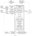
- FIG. 16 is a flowchart of a movement control method for an underactuated robot according to an exemplary embodiment of this application.
- the vehicle wheel portion includes a leg portion and a wheel portion, and step 104 may be implemented as step 1041. Details of step 1041 are as follows.
- Step 1041 Control the wheel portion to move and the base portion to move inclinedly according to the status information, so as to maintain body balance of the underactuated robot and prevent the loaded object from falling from the base portion.
- the inclined movement of the base portion and the movement of the wheel portion interact with each other through stretching/retraction of the leg portion.
- the movement of the wheel portion includes at least moving movement and inclined movement.
- the wheel portion moves in a forward direction.
- the wheel portion moves inclinedly, so that the body of the underactuated robot inclines to avoid the obstacle.
- the wheel portion may include a driving wheel 123, and the second driving motor 1242 provides a driving force to the driving wheel 123, so that the driving wheel 123 performs moving movement and inclined movement.
- the second driving motor 1242 drives the driving wheel 123 to move forward or backward in the forward direction of the underactuated robot 10.
- the second driving motor 1242 drives the driving wheel 123 to be inclined, so that an included angle between the driving wheel 123 and the ground changes, thereby driving the body of the underactuated robot 10 to be inclined.
- the x-axis in the foregoing content is used as an example.
- the base portion is continuously inclined up and down around the x-axis, so that the base portion is in a swaying state in the x-axis direction. If the x-axis is the forward direction of the wheel-legged robot 10, the inclined movement of the base portion may be regarded as a nodding action of the base portion.
- the y-axis in the foregoing content is used as an example.
- the base portion is continuously inclined up and down around the y-axis, so that the base portion is in a swaying state in the y-axis direction. If the y-axis is a dual-wheel connection direction of the wheel-legged robot 10, the inclined movement of the base portion may be regarded as a shaking action of the base portion.
- the loaded object is a sphere by way of example.
- the sphere is enclosed without form closure and force closure on the base portion.
- the balance controller keeps body balance of the underactuated robot by controlling the movement of the vehicle wheel portion and keeps the sphere from falling from the base portion by controlling the movement of the base portion.
- the inclined movement of the base portion and the movement of the wheel portion interact with each other through stretching/retraction of the leg portion.
- the inclined movement of the base portion affects the movement of the wheel portion through the leg portion, and the movement of the wheel portion affects the inclined movement of the base portion through the leg portion.
- the leg portion includes a thigh unit 121 and a calf unit 122
- the wheel portion includes a driving wheel 123, for example.
- the base portion 11 moves inclinedly, the base portion 11 affects the forward and/or backward movement of the driving wheel 123 through stretching/retraction of the thigh unit 121 and the calf unit 122.
- the driving wheel 123 moves forward and/or backward, the driving wheel 123 drives the calf unit 122 and the thigh unit 121 to stretch/retract in sequence, thereby affecting the left-right sway and/or the back-and-forth sway of the base portion 11.
- the movement of the vehicle wheel portion and the inclined movement of the base portion can be realized through the whole-body dynamics control of the underactuated robot, and each joint of the underactuated robot is controlled according to the reference signal outputted by the controller, so as to implement the movement control of the vehicle wheel portion and the base portion.
- This part is to be described in detail later, and is only an example description herein.
- a plurality of movement states of underactuated robot are given, to prevent the loaded object from falling from the base portion, thereby improving the stability of the underactuated robot.
- the wheel portion is controlled to move and the base portion is controlled to move inclinedly according to the status information in a case that the loaded object and/or the underactuated robot is subject to external interference, so as to maintain body balance of the underactuated robot and prevent the loaded object from falling from the base portion.
- the external interference to the loaded object and/or the underactuated robot may be a force applied by other objects to the loaded object and/or the underactuated robot, or may be the resistance encountered by the underactuated robot when crossing or passing an obstacle. For example, when the underactuated robot passes the obstacle, some entities of the obstacle squeeze the base portion, so that the underactuated robot and the loaded object are simultaneously squeezed.
- FIG. 17 to FIG. 19 are diagrams showing implementation of movement control for an underactuated robot under different external interference according to an exemplary embodiment of this application.
- the underactuated robot is a wheel-legged robot 10 by way of example.
- the driving motor of the wheel-legged robot 10 provides a driving force to two driving wheels 123 included by the vehicle wheel portion 12 (not shown), so that the wheel-legged robot 10 is in a dynamic balancing state.
- the two driving wheels 123 are the wheel portions of the vehicle wheel portion 12, the loaded object 20 is placed on the base portion 11, and the wheel-legged robot 10 controls at least one of the base portion 11 and the driving wheels 123 to move, so as to keep the loaded object 20 from falling from the base portion 11.
- an external interference is added to the center of the sphere, so that the loaded object 20 does not fall after rolling on the base portion 11, and the wheel-legged robot 10 still remains balanced.
- the base portion 11 performs closed-loop control in different attitude angle directions.
- a torque is added around the center of mass of the loaded object 20, so that the loaded object 20 does not fall after rolling on the base portion 11, and the wheel-legged robot 10 still remains balanced.
- the base portion 11 also performs closed-loop control in different attitude angle directions.
- the wheel-legged robot 10 controls the driving wheel 123 to move, for example, forward or backward in the wheel rotation direction, so as to keep the loaded object 20 on the base portion 11.
- the balance controller of the wheel-legged robot 10 needs to consider control reference signals of both the base portion 11 and the vehicle wheel portion 12, so that the movement of the vehicle wheel portion 12 can assist the movement of the base portion 11, and the loaded object 20 can be maintained on the base portion 11. It is to be understood that the movement of the vehicle wheel portion 12 and the base portion 11 can be implemented by the controller of the wheel-legged robot 10. For the specific implementation, reference may be made to the foregoing contents, and the details are not described again.
- step 1041 may be implemented by: controlling the wheel portion to move forward in a first direction according to the status information in a case that the loaded object moves on the base portion in the first direction; or controlling one side of the base portion close to the first direction to lift and the other side of the base portion away from the first direction to fall according to the status information in a case that the loaded object moves in the first direction; or controlling the wheel portion to move forward in the first direction and controlling the one side of the base portion close to the first direction to lift and the other side of the base portion away from the first direction to fall according to the status information in a case that the loaded object moves in the first direction.
- the loaded object 20 rolls on the base portion 11, and the first direction is a rolling forward direction of the loaded object 20 by way of example.
- the loaded object 20 rolls in the first direction.
- the underactuated robot 10 may perform one of the following three controlling operations.
- the body of the underactuated robot 10 is kept balanced, and the loaded object 20 is prevented from falling from the base portion 11.
- the driving wheel 123 accelerates in the rolling direction of the loaded object 20, and the base portion 11 remains stationary.
- the driving wheel 123 remains stationary, and two sides of the base portion 11 are lifted or lowered according to the rolling forward direction of the loaded object 20, so that the base portion 11 is inclined and sways.
- the driving wheel 123 moves in cooperation with the base portion 11, so that the underactuated robot 10 moves forward in the rolling forward direction of the loaded object 20, and the base portion 11 is in a swaying state.
- the underactuated robot in a case that the loaded object and/or the underactuated robot is subject to external interference, the underactuated robot can still achieve the goal of keeping the body balance of the underactuated robot and keeping the loaded object from falling from the base portion.
- the embodiment of this application can further provide a plurality of possibilities of external interference. It is to be understood that the plurality of possibilities are only schematic examples. Other possibilities that the loaded object and/or the underactuated robot may be subject to torque impact are all within the protection scope of this application, and the details are not described again.
- FIG. 20 is a flowchart of a movement control method for an underactuated robot according to an exemplary embodiment of this application.
- the method is performed by a controller of the underactuated robot.
- the underactuated robot includes a vehicle wheel portion and a base portion connected to the vehicle wheel portion. A loaded object is placed on the base portion.
- the movement control method provided in the embodiment of this application includes the following steps.
- Step 202 Determine status information of a loaded object on a base portion.
- the movement control method for an underactuated robot provided in the embodiment of this application provides an optional determination manner of the control information of the base portion and/or the vehicle wheel portion.
- the inclination angle acceleration reference value of the base portion is determined based on the status information of the loaded object on the base portion, and the control information is determined based on the value and the whole-body dynamics model, so as to realize the control of the base portion and/or the vehicle wheel portion.
- the displacement is S h
- the movement speed is ⁇ h
- the preset displacement is S h ref
- the preset movement speed is ⁇ h ref
- At least one of S h ref , ⁇ h ref , ⁇ h ref , and ⁇ h ref can be determined according to a structural feature of the underactuated robot.
- the determination of ⁇ h ref and ⁇ h ref is similar to the determination of S h ref and ⁇ h ref , reference may be made to the foregoing contents, and the details are not described again.
- Step 2062 Control at least one of the base portion and the vehicle wheel portion to move according to torque information, so as to prevent the loaded object from falling from the base portion.
- the controller of the underactuated robot transmits information (the information may be torque information) for implementing movement control to the driving motor of the underactuated robot, and the driving motor provides different driving forces according to the corresponding torque information to control the movement of the base portion and/or the vehicle wheel portion.
- the position information of the loaded object on the base portion may be acquired in a plurality of ways.
- a photographing area of the camera can cover the upper surface of the base portion in a case that the position information is acquired through the camera.
- the acquiring the position information of the loaded object on the base portion through a camera may be implemented by: determining the position information according to image information acquired by the camera.
- the contact position coordinate transformation is a process of converting the position information of the loaded object on the base portion into status information.
- the position information is acquired by the tactile sensor by way of example.
- a correspondence between a force signal changing unit and a position of the pressure sensor array on the upper surface of the base portion may be described through the contact position coordinate transformation.
- the relationship between the position of the upper surface of the base portion and the center of mass of the underactuated robot is known, and the contact point of the upper surface of the base portion and the loaded object may be obtained through coordinate conversion, which is equivalent to a position relationship between the loaded object and the center of mass being obtained.
- the position information is acquired by the tactile sensor by way of example.
- the pressure value changes.
- Each unit can output a corresponding pressure value, but the pressure value of the unit that is not pressed is 0 or a very small noise value, and therefore it is necessary to filter out these small noises.
- the process may be regarded as a signal conditioning process.
- the averaging means that the pressure values within a certain range (such as 4*4 dot matrix or several dots in a circular region) are averaged, and the contact point between the loaded object and the underactuated robot is considered to contact the center of several dots.
- the calculation of force distribution means that the pressure value within a certain range is expressed in the form of distribution, and integration processing may be performed on the force value to obtain the magnitude and position distribution of the force, to determine the state of the loaded object.
- the threshold filtering means that because there is a certain probability that the pressure sensor is not detected, some noise may be detected without force, and a threshold is set accordingly. When the detected pressure value is below the threshold, it is considered that the sensor is not triggered.
- Step 1012 Acquire position information and form information of a loaded object on a base portion.
- the form information includes at least one piece of stress information, shape information, structure information, and physical information.
- the stress information refers to a stress value of the loaded object at a certain point on the base portion, and the stress information may be acquired in a plurality of manners.
- the position information is sensed by a tactile sensor or a pressure sensor laid on the base portion.
- the position information is acquired through an action capture system.
- related information such as the position, a displacement direction, a speed, and an acceleration of the loaded object on the base portion may be determined according to the stress information.
- the shape information is an external shape of the loaded object.
- the shape information of the loaded object is a regular sphere or an irregular polyhedron.
- the structure information means that the composition structure of the loaded object includes but is not limited to components of the loaded object, a relative position relationship between components, and shapes and positions of components.
- the physical information is parameter information related to the physical characteristics of the loaded object, such as the mass and moment of inertia of the loaded object.
- the acquisition manners of shape information, structure information, and physical information are similar.
- the information may be sensed by a tactile sensor or a pressure sensor, or may be acquired by a camera, or may be manually inputted into the controller of the underactuated robot by an operator.
- Step 1022 Perform contact position coordinate transformation according to the position information and the form information (for example, the stress information in all embodiments of the present disclosure) to determine the status information.
- the form information for example, the stress information in all embodiments of the present disclosure
- step 1022 is similar to step 1021, which may be used as reference, and details are not described again.
- the controller of the underactuated robot issues an instruction to at least one auxiliary component of the tactile sensor, the pressure sensor, the action capture system, and the camera to acquire the position information or the position information and the stress information (as an example of the form information in all embodiments of the present disclosure) of the loaded object on the base portion.
- at least one auxiliary component reports the position information or the position information and the stress information of the loaded object on the base portion to the controller, and the controller determines the status information according to the position information or the position information and the stress information.
- the position information or the position information and the stress information may be processed by at least one auxiliary component to obtain status information, and then the status information is reported to the controller.
- the movement control method for an underactuated robot provided in the embodiment of this application provides an optional determination manner of the status information.
- the underactuated robot is a wheel-legged robot and the loaded object is a sphere by way of example.
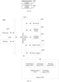
- FIG. 27 is an overall control frame diagram of an underactuated robot according to an exemplary embodiment of this application.
- the wheel-legged robot includes a balance controller and a balance ball controller.
- the balance controller is configured to complete a cycle of balance angle reference to implement body balance of the wheel-legged robot.
- the balance ball controller is configured to implement a cycle of the balance ball reference, so as to achieve the goal of keeping the loaded object from falling from the base portion.
- the wheel-legged robot can estimate the state through state signal collection, and determine a wheel rotation reference signal and other reference signals through the balance controller after the estimation is completed, which are used for controlling the movement of the vehicle wheel portion.
- the wheel rotation reference signal is used for completing a wheel balance task, and other reference signals are used for completing a wheel movement and steering task.
- the wheel-legged robot can perform contact position coordinate transformation through position information collection and/or stress information collection of the loaded object, and then determine a base attitude signal and other reference signals by using the balance ball controller through signal conditioning, which are used for controlling the movement of the base portion.
- the base attitude reference signal is used for completing a base attitude task, and other reference signals are used for completing a tail task.
- the base attitude reference signal may be determined according to the inclination angle acceleration reference value of the base portion mentioned in the foregoing content, and is used for determining at least one of an inclination direction, an inclination angle, and an inclination speed of the base portion.
- the overall movement of the wheel-legged robot is controlled by whole-body dynamics control, and the movement of the vehicle wheel portion and the base portion needs to satisfy the needs of the whole-body dynamics control.
- the control task includes a wheel balancing task, a wheel moving and steering task, a base attitude task, a tail task, a torque task, and an external force task.
- the wheel balancing task is to keep the attitude of an upper body of the robot balanced
- the wheel moving and steering task is a task that satisfies movement forward and backward of the robot and steering in a yaw direction.
- the base attitude task can realize the rotation of the base in pitch, roll, and yaw directions and the translation in x, y, and z directions.
- the tail task may be to place the tail portion to a specified position according to a given joint angle value corresponding to the tail portion.
- the torque task is generally to introduce the integral of a sum of squares of the torque of each joint motor with time into a cost function, so as to ensure that the value of each joint torque falls within a limited value range in the process of optimal solution.
- the external force task includes external forces in three directions corresponding to the contact points between two wheels and the ground respectively.
- the integral of a sum of squares of the external forces with time is introduced into a cost function, so as to ensure that values of the external forces all fall within a limited value range in the process of optimal solution.
- the whole-body dynamics model can be subject to a plurality of constraint conditions.
- the constraint conditions include a dynamics model constraint condition, a closed-loop link constraint, a constraint that no wheel slips or leaves the ground, and a friction constraint.
- an embodiment of this application further provides an underactuated robot.
- the underactuated robot includes a vehicle wheel portion and a base portion connected to the vehicle wheel portion, the base portion being configured to bear a loaded object; a controller being arranged in that underactuated robot, the controller being configured to control the underactuated robot to: control, according to status information of the loaded object on the base portion, at least one of the base portion and the vehicle wheel portion to move, so as to prevent the loaded object from falling from the base portion.
- the controller may be arranged according to the actual needs, which is not limited in this application. All underactuated robots that can achieve the goal of keeping the loaded object from falling from the base portion through the movement control of the controller fall within the protection scope of this application.
- the movement control of the underactuated robot has been described in detail in the foregoing contents, which may be used as a reference, and details are not described again.
- a pressure sensor array can be arranged on an upper surface of the base portion.
- the pressure sensor array is configured to acquire position information of the loaded object on the base portion.
- the density of the pressure sensor array may be limited according to the actual needs. For details, reference is made to the foregoing part, and details are not described again.
- the tactile sensor includes a pressure sensor array arranged in an m ⁇ n matrix, a length and a width of the m ⁇ n matrix matching the upper surface of the base portion, and m and n being positive integers.
- the underactuated robot can further include a camera.
- the camera is configured to acquire the position information of the loaded object on the base portion.
- FIG. 28 is a schematic diagram of a movement control apparatus of an underactuated robot according to an exemplary embodiment of this application.
- the apparatus includes: a determination module 2820, configured to determine status information of a loaded object on a base portion; and a control module 2840, configured to control, according to the determined status information, at least one of the base portion and a vehicle wheel portion to move, so as to prevent the loaded object from falling from the base portion.
- the external interference can include at least one of the following: a center of the loaded object is subject to external interference; a part of the loaded object other than the center is subject to external interference; a center of mass of the loaded object is subject to external interference; a circumferential side of the center of mass of the loaded object is subject to external interference; the base portion is subject to external interference; and the vehicle wheel portion is subject to external interference.
- control module 2840 can be configured to: control the wheel portion to move forward in a first direction according to the status information in a case that the loaded object moves on the base portion in the first direction; or control one side of the base portion close to the first direction to lift and the other side of the base portion away from the first direction to fall according to the status information in a case that the loaded object moves in the first direction; or control the wheel portion to move forward in the first direction and controlling the one side of the base portion close to the first direction to lift and the other side of the base portion away from the first direction to fall according to the status information in a case that the loaded object moves in the first direction.
- control module 2840 can be configured to: determine an inclination angle acceleration reference value of the base portion according to the status information; and control the at least one of the base portion and the vehicle wheel portion to move according to the inclination angle acceleration reference value and a whole-body dynamics model of the underactuated robot.
- the status information can include: a displacement of a contact point of the loaded object on the base portion in a target direction relative to the center of mass of the underactuated robot on the base portion, a movement speed of the contact point on the base portion in the target direction, an inclination angle of the base portion, and an inclination angle speed of the base portion.
- control module 2840 can be configured to: construct the whole-body dynamics model based on a driving torque, a ground friction, and a closed-loop force of the underactuated robot; and substitute the inclination angle acceleration reference value into the whole-body dynamics model to determine the torque information through the PID controller.
- the whole-body dynamics model is constrained by a dynamics model constraint condition, the dynamics model constraint condition including the inclination angle acceleration reference value.
- the determination module 2820 can be configured to: acquire the position information through a tactile sensor laid on the base portion; or acquire the position information through a pressure sensor laid on the base portion; or acquire the position information through an action capture system; or acquire the position information of the loaded object on the base portion through a camera.
- a pressure sensor array can be arranged on an upper surface of the base portion.
- the determination module 2820 is configured to determine the position information through a contact point of the loaded object on the pressure sensor array.
- the tactile sensor includes a pressure sensor array arranged in an m ⁇ n matrix, a length and a width of the m ⁇ n matrix matching the upper surface of the base portion, and m and n being positive integers.
- a photographing area of the camera can cover the upper surface of the base portion.
- the determination module 2820 is configured to determine the position information according to image information acquired by the camera.
- FIG. 29 is a structural block diagram of an electronic device 2900 according to an exemplary embodiment of this application.
- the electronic device 2900 may be a portable mobile terminal, such as an electronic device, a smartphone, a tablet computer, a Moving Picture Experts Group Audio Layer III (MP3) player, a Moving Picture Experts Group Audio Layer IV (MP4) player, a notebook computer, or a desktop computer that is configured to implement the control of the underactuated robot.
- the electronic device 2900 may further be referred to as another name such as user equipment, a portable terminal, a laptop terminal, a desktop terminal, or the like.
- the electronic device 2900 may be implemented as a control device part in a robot.
- the memory 2902 may include one or more computer-readable storage media.
- the computer-readable storage medium may be non-transient.
- the memory 2902 may further include a high-speed random access memory and a nonvolatile memory, for example, one or more disk storage devices or flash storage devices.
- the non-transient computer-readable storage medium in the memory 2902 is configured to store at least one instruction, the at least one instruction being configured to be executed by the processor 2901 to implement the movement control method for an underactuated robot provided in the method embodiments of this application.
- the electronic device 2900 may further optionally include a peripheral device interface 2903 and at least one peripheral device.
- the processor 2901, the memory 2902, and the peripheral device interface 2903 may be connected through a bus or a signal line.
- Each peripheral device may be connected to the peripheral device interface 2903 through a bus, a signal line, or a circuit board.
- the peripheral device includes: at least one of a radio frequency (RF) circuit 2904, a display screen 2905, a camera assembly 2906, an audio circuit 2907, and a power supply 2908.
- RF radio frequency
- the peripheral device interface 2903 may be configured to connect the at least one peripheral device related to input/output (I/O) to the processor 2901 and the memory 2902.
- the processor 2901, the memory 2902, and the peripheral device interface 2903 are integrated on the same chip or circuit board.
- any or both of the processor 2901, the memory 2902, and the peripheral device interface 2903 may be implemented on an independent chip or circuit board, which is not limited in this embodiment.
- the RF circuit 2904 is configured to receive and transmit an RF signal, which is also referred to as an electromagnetic signal.
- the RF circuit 2904 communicates with a communication network and other communication devices through the electromagnetic signal.
- the RF circuit 2904 converts an electric signal into an electromagnetic signal for transmission, or converts a received electromagnetic signal into an electric signal.
- the RF circuit 2904 includes: an antenna system, an RF transceiver, one or more amplifiers, a tuner, an oscillator, a digital signal processor, a codec chip set, a subscriber identity module card, and the like.
- the RF circuit 2904 may communicate with other terminals by using at least one wireless communication protocol.
- the wireless communication protocol includes but is not limited to: the World Wide Web, a metropolitan area network, Intranet, various generations of mobile communication networks (2G, 3G, 4G, and 5G), a wireless local area network, and/or a wireless fidelity (Wi-Fi) network.
- the RF circuit 2904 may further include a near field communication (NFC)-related circuit, which is not limited in this application.
- NFC near field communication
- the display screen 2905 is configured to display a user interface (UI).
- the UI may include a graph, texts, an icon, a video, and any combination thereof.
- the display screen 2905 is a touch display screen
- the display screen 2905 further has the capability of collecting a touch signal on or above a surface of the display screen 2905.
- the touch signal may be inputted to the processor 2901 as a control signal for processing.
- the display screen 2905 may be further configured to provide a virtual button and/or a virtual keyboard, which are/is also referred to as a soft button and/or a soft keyboard.
- one display screen 2905 may be arranged on a front panel of the electronic device 2900.
Landscapes
- Engineering & Computer Science (AREA)
- Mechanical Engineering (AREA)
- Robotics (AREA)
- Human Computer Interaction (AREA)
- Chemical & Material Sciences (AREA)
- Combustion & Propulsion (AREA)
- Transportation (AREA)
- Manipulator (AREA)
Abstract
Description
- This application claims priority to
Chinese Patent Application No. 202210015856.0, entitled "MOVEMENT CONTROL METHOD FOR UNDERACTUATED ROBOT AND UNDERACTUATED ROBOT", and filed on January 07, 2022 - This application relates to the field of robots, and in particular, to a movement control method for an underactuated robot and an underactuated robot.
- An underactuated robot is a robot with fewer drives than degrees of freedom of joints. Typically, the robot has a problem in balance. A wheel-legged robot with a base portion is used as an example. The base portion can float, and the robot moves through a vehicle wheel portion to keep balance. Therefore, it may be understood that the robot with an underactuated system has the problem of body attitude control.
- During the actual use, it is possible to use the underactuated robot to complete the specified task. For example, a wheel-legged robot uses the base portion to transport a spherical object. Since the spherical object has no form seal and force seal on the base portion, the spherical object is in an unstable state on the base portion, causing the possibility of falling. At present, no clear research result is obtained for the control method related to the problem.
- Embodiments of this application provide a movement control method for an underactuated robot and an underactuated robot. At least one of a base portion and a vehicle wheel portion is controlled to move according to status information, so as to ensure that a loaded object is prevented from falling from the base portion, so as to improve the stability of the underactuated robot. The technical solution includes at least the following solutions.
- According to an aspect of this application, a movement control method for an underactuated robot is provided, the method being performed by a controller of the underactuated robot, the underactuated robot including a vehicle wheel portion and a base portion connected to the vehicle wheel portion, a loaded object being placed on the base portion, and the method including:
- determining status information of the loaded object on the base portion; and
- controlling, according to the determined status information, at least one of the base portion and the vehicle wheel portion to move, so as to prevent the loaded object from falling from the base portion.
- According to an aspect of this application, an underactuated robot is provided, including a vehicle wheel portion and a base portion connected to the vehicle wheel portion, the base portion being configured to bear a loaded object;
a controller being arranged in that underactuated robot, the controller being configured to control the underactuated robot to: control, according to status information of the loaded object on the base portion, at least one of the base portion and the vehicle wheel portion to move, so as to prevent the loaded object from falling from the base portion. - According to an aspect of this application, a movement control apparatus for an underactuated robot is provided, the apparatus including:
- a determination module, configured to determine status information of a loaded object on a base portion; and
- a control module, configured to control, according to the determined status information, at least one of the base portion and a vehicle wheel portion to move, so as to prevent the loaded object from falling from the base portion.
- According to an aspect of this application, a computer device is provided, including a processor,
- the processor being configured to: determine status information of a loaded object on a base portion; and
- control, according to the determined status information, at least one of the base portion and the vehicle wheel portion to move, so as to prevent the loaded object from falling from the base portion.
- According to an aspect of this application, a computer-readable storage medium is provided, the storage medium storing a computer program, the computer program being executed by a processor to implement the movement control method for an underactuated robot according to any one of the above embodiments of this application.
- According to an aspect of this application, a chip is provided, including a programmable logic circuit and/or program instructions, the chip, when run, being configured to implement the movement control method for an underactuated robot according to any one of the above embodiments.
- According to an aspect of this application, a computer program product is provided, including computer instructions stored in a computer-readable storage medium, a processor reading the computer instructions from the computer-readable storage medium and executing the computer instructions, to implement the movement control method for an underactuated robot according to any one of the above embodiments.
- Beneficial effects brought by the technical solutions provided in the embodiments of this application include at least the following.
- The underactuated robot can control the base portion and/or the vehicle wheel portion to move according to the status information of the loaded object on the base portion, to prevent the loaded object from falling from the base portion, thereby improving the stability of the underactuated robot.
-
-
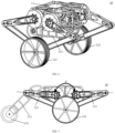
FIG. 1 is a schematic structural diagram of a wheel-legged robot according to an exemplary embodiment of this application. -
FIG. 2 is a partial schematic diagram of a wheel-legged robot according to an exemplary embodiment of this application. -
FIG. 3 is a front view of a wheel-legged robot standing with two wheels according to an exemplary embodiment of this application. -
FIG. 4 is a side view of a wheel-legged robot standing with two wheels according to an exemplary embodiment of this application. -
FIG. 5 is a top view of a wheel-legged robot standing with two wheels according to an exemplary embodiment of this application. -
FIG. 6 shows a schematic three-dimensional view of a wheel-legged robot with a counterweight leg being in a retracted state according to an exemplary embodiment of this application. -
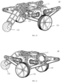
FIG. 7 is a front view of a wheel-legged robot standing with three wheels according to an exemplary embodiment of this application. -
FIG. 8 is a side view of a wheel-legged robot standing with three wheels according to an exemplary embodiment of this application. -
FIG. 9 is a top view of a wheel-legged robot standing with three wheels according to an exemplary embodiment of this application. -
FIG. 10 is a schematic three-dimensional view of a wheel-legged robot standing with three wheels according to an exemplary embodiment of this application. -
FIG. 11 is another schematic three-dimensional view of a wheel-legged robot standing with three wheels according to an exemplary embodiment of this application. -
FIG. 12 is a schematic form diagram of a wheel-legged robot according to an exemplary embodiment of this application. -
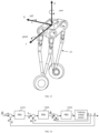
FIG. 13 is a schematic diagram of three space angles according to an exemplary embodiment of this application. -
FIG. 14 is a block diagram of balance control in a pitch angle direction according to an exemplary embodiment of this application. -
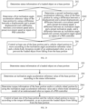
FIG. 15 is a flowchart of a movement control method for an underactuated robot according to an exemplary embodiment of this application. -
FIG. 16 is a flowchart of a movement control method for an underactuated robot according to an exemplary embodiment of this application. -
FIG. 17 is a diagram showing implementation of movement control for an underactuated robot under external interference according to an exemplary embodiment of this application. -
FIG. 18 is a diagram showing implementation of movement control for an underactuated robot under external interference according to an exemplary embodiment of this application. -
FIG. 19 is a diagram showing implementation of movement control for an underactuated robot under external interference according to an exemplary embodiment of this application. -
FIG. 20 is a flowchart of a movement control method for an underactuated robot according to an exemplary embodiment of this application. -
FIG. 21 is a schematic diagram showing common problems when grasping an object by hand according to an exemplary embodiment of this application. -
FIG. 22 is a schematic diagram of scalar definition of an underactuated robot according to an exemplary embodiment of this application. -
FIG. 23 is a flowchart of a movement control method for an underactuated robot according to an exemplary embodiment of this application. -
FIG. 24 is a flowchart of a movement control method for an underactuated robot according to an exemplary embodiment of this application. -
FIG. 25 is a schematic diagram of generalized coordinates of an underactuated robot according to an exemplary embodiment of this application. -
FIG. 26 is a flowchart of a movement control method for an underactuated robot according to an exemplary embodiment of this application. -
FIG. 27 is an overall control frame diagram of an underactuated robot according to an exemplary embodiment of this application. -
FIG. 28 is a schematic diagram of a movement control apparatus of an underactuated robot according to an exemplary embodiment of this application. -
FIG. 29 is a block diagram of an electronic device according to an exemplary embodiment of this application. -
FIG. 30 is a structural block diagram of an underactuated robot according to an exemplary embodiment of this application. - Reference numerals in the accompanying drawings are described below.
- 10-Wheel-legged robot;
- 11-Base portion;
- 12-Vehicle wheel portion; 121-Thigh unit; 122-Calf unit; 123-Driving wheel; 124-Driving unit; 1241-First driving motor; 1242-Second driving motor;
- 13-Tail portion; 131-Counterweight leg; 132-Driven wheel; 133-Third driving motor;
- 01-Torsion spring; 02-Rotary shaft; 03-Synchronous belt; 04-Synchronous pulley;
- 20-Loaded object.
- Unless otherwise defined, all technical terms used in embodiments of this application have the same meaning as commonly understood by a person skilled in the art. In the embodiments of this application, "front" and "back" involved are based on front and back shown in the accompanying drawings. "First end" and "second end" are two opposite ends. To make the objectives, technical solutions, and advantages of this application clearer, the following further describes implementations of this application in detail with reference to the accompanying drawings.
- An underactuated robot is a robot with fewer drives than degrees of freedom of joints. The underactuated robot generally has the problem of body balance.
-
FIG. 1 shows a wheel-legged robot 10 according to an exemplary embodiment of this application. The wheel-legged robot 10 is a type of underactuated robot, and a movement control method for an underactuated robot provided in the embodiment of this application can be implemented by the wheel-legged robot. The wheel-legged robot 10 combines the advantages of a wheeled robot and a biped robot, has high wheel energy efficiency, and strong adaptability, and can avoid obstacles by using legs on the uneven ground. The wheel-legged robot 10 is an unstable underactuated system, and only two contact points are provided between the ground and the wheels/legs, which leads to challenging balance control of the wheel-legged robot 10 because it is difficult to achieve the body balance. - For example, the wheel-
legged robot 10 includes abase portion 11,vehicle wheel portions 12, and atail portion 13. Thevehicle wheel portion 12 and thetail portion 13 are respectively drive-connected to thebase portion 11. Optionally, thevehicle wheel portions 12 may be arranged on left and right sides, which may be completely symmetrical or not completely symmetrical on the left and right sides. - For example, each of the
vehicle wheel portions 12 includes a leg portion and a wheel portion. The leg portion includes athigh unit 121 and acalf unit 122, and the wheel portion includes adriving wheel 123. For example, thethigh unit 121 is composed of two rods and thecalf unit 122 is composed of two rods. The two rods included by thethigh unit 121, the two rods included by thecalf unit 122, and thebase portion 11 form a planar five-link mechanism. - In the embodiments of the present disclosure including the embodiments of both the claims and the specification (hereinafter referred to as "all embodiments of the present disclosure"), the
first driving motor 1241 can be fixed to thebase portion 11 for providing a driving force to thethigh unit 121. - The
first driving motor 1241 includes two motors by way of example. Two rods included by thethigh unit 121 are respectively fixedly connected to output shafts of the two motors included by thefirst driving motor 1241, and connected ends of the two rods included by thethigh unit 121 and the two rods included by thecalf unit 122 are all in the form of rotating pairs to form a planar five-link mechanism. - In all embodiments of the present disclosure, a
second driving motor 1242 can be fixed to a certain rod of thecalf unit 122 for providing a driving force to thedriving wheel 123. - Referring to the partial schematic diagram of the wheel-
legged robot 10 shown inFIG. 2 , the driving of thedriving wheel 123 can be implemented in the following manner. Thesecond driving motor 1242 drives therotary shaft 02 of thedriving wheel 123 through belt transmission. Therotary shaft 02 is coaxial with an axial direction of the rotating pair between the two rods included by thecalf unit 122. Thetorsion spring 01 is sleeved on therotary shaft 02, and arms of thetorsion spring 01 are respectively fixed to the two rods included by thecalf unit 122. - In all embodiments of the present disclosure, a
synchronous pulley 04 can be mounted to the output shaft of thesecond driving motor 1242, thesynchronous pulley 04 can be fixed to therotary shaft 02, and thedriving wheel 123 can be fixed to the other section of therotary shaft 02. Thesynchronous belt 03 is sleeved on thesynchronous pulley 04. Thesecond driving motor 1242 drives thesynchronous pulley 04 to rotate by driving thesynchronous belt 03, thereby driving thedriving wheel 123 to rotate. - In all embodiments of the present disclosure, in the wheel-
legged robot 10 provided in the embodiment of this application, thetail portion 13 can include acounterweight leg 131, a drivenwheel 132, and athird driving motor 133. Thecounterweight leg 131 implements the balancing function during the movement of the wheel-legged robot 10, and thethird driving motor 133 is configured to provide a driving force to the drivenwheel 132. -
FIG. 3 to FIG. 5 respectively show a front view, a left view, and a top view of a wheel-legged robot 10 standing with two wheels.FIG. 6 shows a schematic three-dimensional view of a wheel-legged robot 10 with acounterweight leg 131 being in a retracted state. - In an optional implementation scenario, the wheel-
legged robot 10 may further be in a state of standing with three wheels. In a case that the wheel-legged robot 10 is in the state of standing with three wheels,FIG. 7 to FIG. 9 respectively show a front view, a left view, and a top view of a wheel-legged robot 10 standing with three wheels.FIG. 10 and FIG. 11 respectively show different three-dimensional views of a wheel-legged robot 10 standing with three wheels. - Referring to
FIG. 7 , a position angle formed by the axis lines of the two rods included by thethigh unit 121 is θ by way of example, and the position angle θ is < 180°, and the mechanism may be in a self-stable state. In an optional implementation scenario, the wheel-legged robot 10 may further have other forms, and an example of one form is given inFIG. 12 . - It is to be understood that the wheel-
legged robot 10 is a type of underactuated robot, and the following embodiments of this application only use the wheel-legged robot 10 as an example. The specific structure and form of the wheel-legged robot 10 may be set according to the actual situation, which does not constitute a limitation on this application. - In order to realize the balance of the wheel-
legged robot 10, it is usually necessary to perform balance feedback control on the wheel-legged robot 10. The balance feedback control mainly means that a self-balance measurement value is fed back to a control system, so that the final balance measurement value can reach the standard. - For example,
FIG. 13 is a schematic diagram of three space angles according to an exemplary embodiment of this application. The embodiment of this application mainly realizes the balance through three space angles: a pitch angle, a yaw angle, and a roll angle. - Referring to
FIG. 13 , a right-hand Cartesian coordinate system of a three-dimensional control is established for the wheel-legged robot 10. The pitch angle is an angle of rotation around an x-axis, the x-axis is a coordinate axis in a forward direction of the wheel-legged robot 10, and the corresponding roll angle is expressed by θ later. The yaw angle is an angle of rotation around a y-axis, the y-axis is a coordinate axis in a dual-wheel connection direction of the wheel-legged robot 10, and the corresponding pitch angle is expressed by φ later. The roll angle is an angle of rotation around the z-axis, the z-axis is a coordinate axis in a vertical upward direction, and the corresponding yaw angle is expressed by ϕ later. - The balance control in the pitch angle direction is used as an example to describe the balance control.
- The angle in the pitch direction indicates a sway amplitude of the wheel-
legged robot 10 in the forward direction, that is, the angle in the pitch direction indicates the angle at which the wheel-legged robot 10 sways back and forth in the control direction of wheel rotation, because only a single contact point exists between each vehicle wheel and a movement surface, and the wheels of the wheel-legged robot 10 are transversely arranged. - The control in the pitch direction is implemented by a plurality of closed-loop proportional-integral-derivative (PID) controllers. The wheel-
legged robot 10 is projected onto a two-dimensional plane to form a simplified two-dimensional plane model. X represents a distance that the wheel center moves transversely in the simplified two-dimensional plane model. Assuming that no wheel slips or leaves the ground, X is equal to the product of the angle of rotation of the wheel and a radius of the wheel. - For example, Ẋ represents a movement speed of the wheel center, Ẋ ref represents a reference speed of wheel center movement, and θ represents the pitch angle of the wheel-
legged robot 10, that is, the angle of rotation around the direction perpendicular to the paper in the simplified two-dimensional plane model. Correspondingly, θ̇ represents the pitch angle speed of the wheel-legged robot 10, θ̇ ref represents a pitch angle speed reference value of the wheel-legged robot 10, and τ represents a torque inputted to a vehicle wheel motor of the wheel-legged robot 10. θ, θ̇, and Ẋ are collected by a sensor. For example, θ and θ̇ are acquired by an inertial measurement unit (IMU), and Ẋ is acquired by an encoder sensor of the wheel. -
FIG. 14 shows a block diagram of balance control in a pitch direction according to an exemplary embodiment of this application. The outermost control reference quantity is a reference value Ẋ ref of the movement speed of the wheel center. - First, the reference speed Ẋ ref of the wheel center movement is acquired, that is, the speed that the wheel needs to reach according to the expected movement, the movement speed Ẋ of the wheel center is collected by the sensor, a result obtained after Ẋ ref and the movement speed Ẋ of the wheel center are subtracted is inputted to the
PID controller 1410, and θ ref is obtained through the output of thePID controller 1410. - Secondly, θ ref is used as the control reference quantity for a next control loop. After θ ref and θ are subtracted, a pitch angle difference is obtained, that is, a difference between a current pitch angle and a reference pitch angle, and the pitch angle difference is inputted to the
PID controller 1420, to obtain θ̇ ref. Subsequently, θ̇ ref is used as the control reference quantity for the next control loop, the result obtained after the subtraction of θ̇ ref and θ̇ is inputted to thePID controller 1430, and τ is obtained through the output of thePID controller 1430. The balance control of the robot can be implemented by transmitting τ to the wheel motor of the wheel-legged robot 10. - In addition, after the state of the wheel-
legged robot 10 changes correspondingly, values of θ, θ̇, and Ẋ change correspondingly, and these values are acquired by sensors and used in a new round of control of the wheel-legged robot 10, thereby forming closed-loop control. - τ obtained according to the above balance control may be used as a wheel rotation reference signal of a type controller of the whole body of the wheel-
legged robot 10. A plurality of calculation and generation methods for the reference signal are provided. This application is only an illustrative example, and other calculation and generation methods for obtaining τ do not limit this application. - For example, the balance control of the yaw angle and the roll angle in the roll direction is similar to that in the pitch direction of the pitch angle, which may be used as reference, and the details are not described again.
- Based on the foregoing content, this application provides a movement control method for an underactuated robot, which can enable the underactuated robot to maintain a loaded object on a base portion.
-
FIG. 15 shows a flowchart of a movement control method for an underactuated robot according to an exemplary embodiment of this application. The underactuated robot includes a vehicle wheel portion and a base portion connected to the vehicle wheel portion, and a loaded object is placed on the base portion. - The method is implemented by a controller of the underactuated robot, and the movement control of the underactuated robot can be implemented by the controller. For example, after the movement mode of the vehicle wheel portion and/or the base portion is determined, the controller respectively transmits control information to different motors to control the movement of the vehicle wheel portion and/or the base portion.
- It is to be understood that the controller may be arranged inside the underactuated robot, for example, implemented as an internal actuator of the underactuated robot. Alternatively, the controller may be arranged in an external device, for example, implemented as a remote controller of an underactuated robot, implemented as a terminal device (such as a computer device) that performs command control on the underactuated robot, or the like. Alternatively, the controller may further be implemented as other devices, or an execution component in other devices, and the details are not described again.
- For example, the movement control method provide in the embodiment of this application includes the following steps.
- Step 102: Determine status information of a loaded object on a base portion.
- For example, the loaded object is in physical contact with the base portion, but the loaded object has no form closure and force closure on the base portion.
- During the movement of the underactuated robot, a contact point between the loaded object and the base portion is not fixed, which causes the movement state of the loaded object to have no clear rules. However, since the loaded object is placed on the base portion, the underactuated robot needs to consider the physical characteristics of the loaded object during the movement, such as mass and moment of inertia, and different physical parameters generate great differences in the interaction between the loaded object and the underactuated robot.
- The loaded object may be any object, including a rigid object and an elastic object. A shape, a material, a size, and a structure of the loaded object are not limited in this application, and any one or more objects may be regarded as the loaded object involved in this application. When a plurality of objects are regarded as loaded objects involved in this application, the status information of each object on the base portion may be determined separately. Physical information of the plurality of objects may also be processed to determine overall status information.
- The loaded object may be a regular or irregular object such as a cube, a cuboid, a cylinder, a sphere, or the like. If the loaded object is a cube, less friction exists between the cube and the base portion, so that the cube slides on the base portion.
- The loaded object is a sphere by way of example in the following embodiments.
- For example, the status information of the loaded object on the base portion includes at least one of attitude information of the loaded object, movement information of the loaded object, physical information of the loaded object, attitude information of the base portion, movement information of the base portion, and physical information of the base portion. The attitude information of the loaded object is used for indicating a position of the loaded object on the base portion. The movement information of the loaded object includes but is not limited to displacement information, speed information, and acceleration information of the loaded object. The physical information of the loaded object includes but is not limited to parameter information related to the physical characteristics of the loaded object, such as the mass and moment of inertia of the loaded object. For the attitude information, the movement information, and the physical information of the base portion, reference may be made to the above contents, and the details are not described again.
- For example, the status information includes: a displacement of a contact point of the loaded object on the base portion in an x direction relative to a center of mass of the underactuated robot on the base portion, and a movement speed of the contact point on the base portion in the x direction. For another example, the status information includes: a displacement of a contact point of the loaded object on the base portion in an x direction relative to the center of mass of the underactuated robot on the base portion, a movement speed of the contact point on the base portion in the x direction, an inclination angle of the base portion, and an inclination angle speed of the base portion.
- The x direction is the x-axis direction in the foregoing content, and the x-axis is the coordinate axis in the forward direction of the wheel-legged robot, which corresponds to the roll angle. Optionally, the status information may further include relevant information in the y direction, the y direction is the y-axis direction in the foregoing content, and the y-axis is the coordinate axis in the dual-wheel connection direction of the wheel-
legged robot 10, which corresponds to the pitch angle. - In an optionally implementation scenario, the status information may be obtained through at least one auxiliary component of a tactile sensor, a pressure sensor, an action capture system, and a camera (which will be described in detail below). For example, step 102 may be implemented by: acquiring position information of the loaded object on the base portion through the tactile sensor; and performing contact position coordinate transformation according to the position information to determine the status information.
- The movement control method for an underactuated robot provided based on the embodiment of this application is performed by the controller of the underactuated robot. When movement control is needed, the controller issues an instruction to at least one auxiliary component of the tactile sensor, the pressure sensor, the action capture system, and the camera to acquire the position information of the loaded object on the base portion. Subsequently, at least one auxiliary component reports the position information of the loaded object on the base portion to the controller, and the controller determines the status information according to the position information. Alternatively, the position information may be processed by at least one auxiliary component to obtain status information, and then the status information is reported to the controller for further processing by the controller.
- Step 104: Control, according to the determined status information, at least one of the base portion and the vehicle wheel portion to move, so as to prevent the loaded object from falling from the base portion.
- For example, the keeping the loaded object from falling from the base portion includes but is not limited to at least one of the following situations: the loaded object remains stationary on the base portion, moves on the base portion, rotates on the base portion, bounces on the base portion, and rolls on the base portion. The loaded object is a sphere by way of example. The sphere remains stationary, rolling, or bouncing on the base portion, all of which may be regarded that the sphere is maintained on the base portion.
- In this application, the movement state of the underactuated robot is selected according to the actual needs, which is not limited. The movement state of the underactuated robot includes but is not limited to at least one of a stationary state, a moving state, a flipping state, a dancing state, a jumping state, a static balancing state, or a dynamic balancing state.
- For example, when the underactuated robot is in a stationary state, the vehicle wheel portion keeps the base portion at a fixed position relative to the ground. For another example, when the underactuated robot is in a moving state, the vehicle wheel portion moves to keep a body of the underactuated robot balanced. For another example, when the underactuated robot is in the flipping state, a relative position of the vehicle wheel portion and the base portion varies with different flipping stages. For another example, when the underactuated robot is in the dancing state, the vehicle wheel portion moves or moves inclinedly, and/or the base portion moves or move inclinedly.
- In all embodiments of the present disclosure, in the static balancing state, the body of the underactuated robot can be not displaced, and the base portion can be kept stationary or move inclinedly, so that the underactuated robot is in a balanced state in situ, which may be considered that the underactuated robot is in a relatively static state. It is to be understood that in the static balancing state, the vehicle wheel portion may shake slightly in situ, which is caused by the whole-body dynamics model of the underactuated robot. Any shaking within the error range may be regarded as that the vehicle wheel portion remains in situ, and the error range may be set according to actual needs.
- In all embodiments of the present disclosure, in the dynamic balancing state, the body of the underactuated robot can be displaced, the vehicle wheel portion can move, and the base portion can be kept stationary or move inclinedly, so that the underactuated robot is in a balanced state during the displacement.
- The movement state of the underactuated robot is the dynamic balancing state by way of example. In the control process of the underactuated robot, the underactuated robot moves in any direction to ensure body balance. In this case, the loaded object is placed on the base portion, and after the status information of the loaded object on the base portion is determined, the at least one of the base portion and the vehicle wheel portion is controlled to move according to the determined status information, so as to ensure that the underactuated robot can keep the loaded object on the base portion while realizing the body balance.
- For example, the movement of the base portion includes at least inclined movement, and the continuous inclined movement of the base portion may cause the base portion to be in a swaying state, such as nodding or shaking a head of the base portion. The movement of the vehicle wheel portion includes at least moving movement and inclined movement, for example, the movement of the vehicle wheel portion toward a forward direction.
- After the status information of the loaded object on the base portion is determined, the at least one of the base portion and the vehicle wheel portion according to the status information can be controlled by the whole-body dynamics control of the underactuated robot.
- The whole-body dynamics control is implemented by a balance controller by way of example. The status information is inputted into the balance controller of the underactuated robot, and a generated relevant reference signal for the whole-body dynamics control is outputted through the corresponding whole-body dynamics model to drive the at least one of the base portion and the vehicle wheel portion. The relevant reference signal includes but is not limited to at least one of the following signals: a reference signal of wheel rotation, a reference signal of a base portion attitude, and a reference signal of a tail portion attitude. The output of the balance controller is torque information of each joint, and the movement of the base portion and/or the vehicle wheel portion may be determined according to the determined torque information. Optionally, the balance controller is a PID controller.
- For example, after the status information is determined, the controller of the underactuated robot determines the relevant reference signal for the whole-body dynamics control based on a balance processor. Subsequently, the controller transmits the relevant reference signal to the base portion and/or the vehicle wheel portion, so that the base portion and/or the vehicle wheel portion can move according to the transmitted signal. For example, the controller transmits the torque information of each joint of the vehicle wheel portion to the corresponding motor, so that the motor controls the corresponding joint based on the corresponding torque information, thereby realizing the movement of the vehicle wheel portion.
- Based on the above, according to the movement control method for an underactuated robot provided in the embodiment of this application, the underactuated robot can control the base portion and/or the vehicle wheel portion to move through the controller according to the status information of the loaded object on the base portion, to prevent the loaded object from falling from the base portion, thereby improving the stability of the underactuated robot.
- According to the foregoing content, a plurality of movement states of the underactuated robot are provided. The movement state is a dynamic balancing state by way of example. The underactuated robot needs to keep the body balance and prevent the loaded object from falling from the base portion.
- Based on
FIG. 15, FIG. 16 is a flowchart of a movement control method for an underactuated robot according to an exemplary embodiment of this application. Optionally, the vehicle wheel portion includes a leg portion and a wheel portion, and step 104 may be implemented asstep 1041. Details ofstep 1041 are as follows. - Step 1041: Control the wheel portion to move and the base portion to move inclinedly according to the status information, so as to maintain body balance of the underactuated robot and prevent the loaded object from falling from the base portion.
- The inclined movement of the base portion and the movement of the wheel portion interact with each other through stretching/retraction of the leg portion.
- For example, the movement of the wheel portion includes at least moving movement and inclined movement. For example, the wheel portion moves in a forward direction. For another example, when passing an obstacle, the wheel portion moves inclinedly, so that the body of the underactuated robot inclines to avoid the obstacle.
- Referring to
FIG. 1 , the wheel portion may include adriving wheel 123, and thesecond driving motor 1242 provides a driving force to thedriving wheel 123, so that thedriving wheel 123 performs moving movement and inclined movement. For example, thesecond driving motor 1242 drives thedriving wheel 123 to move forward or backward in the forward direction of theunderactuated robot 10. Alternatively, thesecond driving motor 1242 drives thedriving wheel 123 to be inclined, so that an included angle between thedriving wheel 123 and the ground changes, thereby driving the body of theunderactuated robot 10 to be inclined. - For example, the movement of the base portion includes at least inclined movement, and the continuous inclined movement of the base portion may cause the base portion to be in a swaying state.
- For example, referring to
FIG. 13 , the x-axis in the foregoing content is used as an example. The base portion is continuously inclined up and down around the x-axis, so that the base portion is in a swaying state in the x-axis direction. If the x-axis is the forward direction of the wheel-legged robot 10, the inclined movement of the base portion may be regarded as a nodding action of the base portion. For another example, the y-axis in the foregoing content is used as an example. The base portion is continuously inclined up and down around the y-axis, so that the base portion is in a swaying state in the y-axis direction. If the y-axis is a dual-wheel connection direction of the wheel-legged robot 10, the inclined movement of the base portion may be regarded as a shaking action of the base portion. - The loaded object is a sphere by way of example. The sphere is enclosed without form closure and force closure on the base portion. In the control process of the underactuated robot, the balance controller keeps body balance of the underactuated robot by controlling the movement of the vehicle wheel portion and keeps the sphere from falling from the base portion by controlling the movement of the base portion.
- For example, the inclined movement of the base portion and the movement of the wheel portion interact with each other through stretching/retraction of the leg portion. The inclined movement of the base portion affects the movement of the wheel portion through the leg portion, and the movement of the wheel portion affects the inclined movement of the base portion through the leg portion.
- Referring to
FIG. 1 , the leg portion includes athigh unit 121 and acalf unit 122, and the wheel portion includes adriving wheel 123, for example. When thebase portion 11 moves inclinedly, thebase portion 11 affects the forward and/or backward movement of thedriving wheel 123 through stretching/retraction of thethigh unit 121 and thecalf unit 122. When thedriving wheel 123 moves forward and/or backward, thedriving wheel 123 drives thecalf unit 122 and thethigh unit 121 to stretch/retract in sequence, thereby affecting the left-right sway and/or the back-and-forth sway of thebase portion 11. - The movement of the vehicle wheel portion and the inclined movement of the base portion can be realized through the whole-body dynamics control of the underactuated robot, and each joint of the underactuated robot is controlled according to the reference signal outputted by the controller, so as to implement the movement control of the vehicle wheel portion and the base portion. This part is to be described in detail later, and is only an example description herein.
- Based on the above, according to the movement control method for an underactuated robot provided in the embodiment of this application, a plurality of movement states of underactuated robot are given, to prevent the loaded object from falling from the base portion, thereby improving the stability of the underactuated robot.
- In an optional implementation scenario, the loaded object and/or the underactuated robot is to be subject to external interference. Based on this,
step 1041 can be implemented as follows. - The wheel portion is controlled to move and the base portion is controlled to move inclinedly according to the status information in a case that the loaded object and/or the underactuated robot is subject to external interference, so as to maintain body balance of the underactuated robot and prevent the loaded object from falling from the base portion.
- The external interference to the loaded object and/or the underactuated robot may be a force applied by other objects to the loaded object and/or the underactuated robot, or may be the resistance encountered by the underactuated robot when crossing or passing an obstacle. For example, when the underactuated robot passes the obstacle, some entities of the obstacle squeeze the base portion, so that the underactuated robot and the loaded object are simultaneously squeezed.
- For example, the external interference includes at least one of the following: a center of the loaded object is subject to external interference; a part of the loaded object other than the center is subject to external interference; a center of mass of the loaded object is subject to external interference; a circumferential side of the center of mass of the loaded object is subject to external interference; the base portion is subject to external interference; and the vehicle wheel portion is subject to external interference.
-
FIG. 17 to FIG. 19 are diagrams showing implementation of movement control for an underactuated robot under different external interference according to an exemplary embodiment of this application. - The underactuated robot is a wheel-
legged robot 10 by way of example. The driving motor of the wheel-legged robot 10 provides a driving force to two drivingwheels 123 included by the vehicle wheel portion 12 (not shown), so that the wheel-legged robot 10 is in a dynamic balancing state. The two drivingwheels 123 are the wheel portions of thevehicle wheel portion 12, the loadedobject 20 is placed on thebase portion 11, and the wheel-legged robot 10 controls at least one of thebase portion 11 and the drivingwheels 123 to move, so as to keep theloaded object 20 from falling from thebase portion 11. - Alternatively, the loaded
object 20 is a sphere. - Referring to
FIG. 17 , an external interference is added to the center of the sphere, so that the loadedobject 20 does not fall after rolling on thebase portion 11, and the wheel-legged robot 10 still remains balanced. In the process of maintaining balance, thebase portion 11 performs closed-loop control in different attitude angle directions. - Referring to
FIG. 18 , an external interference is added to other positions rather than the center of the sphere, so that the loadedobject 20 does not fall after rolling on thebase portion 11, and the wheel-legged robot 10 still remains balanced. In the process of maintaining balance, thebase portion 11 also performs closed-loop control in different attitude angle directions. - Referring to
FIG. 19 , a torque is added around the center of mass of the loadedobject 20, so that the loadedobject 20 does not fall after rolling on thebase portion 11, and the wheel-legged robot 10 still remains balanced. In the process of maintaining balance, thebase portion 11 also performs closed-loop control in different attitude angle directions. - In all embodiments of the present disclosure, in a case that the loaded object and/or the underactuated robot is to be subject to external interference, there is a higher possibility that the loaded object and/or the underactuated robot is to be subject to greater external interference. In this case, a possibility that the loaded
object 20 cannot be maintained on thebase portion 11 exists only by the movement of thebase portion 11. In this case, the wheel-legged robot 10 controls thedriving wheel 123 to move, for example, forward or backward in the wheel rotation direction, so as to keep theloaded object 20 on thebase portion 11. - In this case, the balance controller of the wheel-
legged robot 10 needs to consider control reference signals of both thebase portion 11 and thevehicle wheel portion 12, so that the movement of thevehicle wheel portion 12 can assist the movement of thebase portion 11, and the loadedobject 20 can be maintained on thebase portion 11. It is to be understood that the movement of thevehicle wheel portion 12 and thebase portion 11 can be implemented by the controller of the wheel-legged robot 10. For the specific implementation, reference may be made to the foregoing contents, and the details are not described again. - In all embodiments of the present disclosure,
step 1041 may be implemented by:
controlling the wheel portion to move forward in a first direction according to the status information in a case that the loaded object moves on the base portion in the first direction; or controlling one side of the base portion close to the first direction to lift and the other side of the base portion away from the first direction to fall according to the status information in a case that the loaded object moves in the first direction; or controlling the wheel portion to move forward in the first direction and controlling the one side of the base portion close to the first direction to lift and the other side of the base portion away from the first direction to fall according to the status information in a case that the loaded object moves in the first direction. - Referring to
FIG. 17 to FIG. 19 , the loadedobject 20 rolls on thebase portion 11, and the first direction is a rolling forward direction of the loadedobject 20 by way of example. The loadedobject 20 rolls in the first direction. In order to keep theloaded object 20 from falling from thebase portion 11, theunderactuated robot 10 may perform one of the following three controlling operations. - 1. The
driving wheel 123 is controlled to move, so that thedriving wheel 123 moves forward in the rolling forward direction of the loadedobject 20. - 2. The
underactuated robot 10 may control a side of thebase portion 11 close to the rolling forward direction of the loadedobject 20 to lift and the other side away from the rolling forward direction of the loadedobject 20 to fall, so that thebase portion 11 performs inclined movement. - 3. In a case that the loaded
object 20 rolls at a relatively high speed, or is subject to relatively great external interference, theunderactuated robot 10 may control, by controlling thedriving wheel 123 to move, a side of thebase portion 11 close to the rolling forward direction of the loadedobject 20 to lift and the other side away from the rolling forward direction of the loadedobject 20 to fall. - Through the movement of the
driving wheel 123 and/or the lifting and falling of two sides of thebase portion 11, the body of theunderactuated robot 10 is kept balanced, and the loadedobject 20 is prevented from falling from thebase portion 11. For example, thedriving wheel 123 accelerates in the rolling direction of the loadedobject 20, and thebase portion 11 remains stationary. For another example, thedriving wheel 123 remains stationary, and two sides of thebase portion 11 are lifted or lowered according to the rolling forward direction of the loadedobject 20, so that thebase portion 11 is inclined and sways. For another example, thedriving wheel 123 moves in cooperation with thebase portion 11, so that theunderactuated robot 10 moves forward in the rolling forward direction of the loadedobject 20, and thebase portion 11 is in a swaying state. - Based on the above, according to the movement control method for an underactuated robot provided in the embodiments of this application, the vehicle wheel portion is controlled to move and the base portion is controlled to move inclinedly through the controller according to the status information of the loaded object on the base portion, so as to keep the body balance of the underactuated robot and prevent the loaded object from falling from the base portion.
- In all embodiments of the present disclosure, in a case that the loaded object and/or the underactuated robot is subject to external interference, the underactuated robot can still achieve the goal of keeping the body balance of the underactuated robot and keeping the loaded object from falling from the base portion.
- In all embodiments of the present disclosure, the embodiment of this application can further provide a plurality of possibilities of external interference. It is to be understood that the plurality of possibilities are only schematic examples. Other possibilities that the loaded object and/or the underactuated robot may be subject to torque impact are all within the protection scope of this application, and the details are not described again.
- Based on the foregoing content,
FIG. 20 is a flowchart of a movement control method for an underactuated robot according to an exemplary embodiment of this application. The method is performed by a controller of the underactuated robot. The underactuated robot includes a vehicle wheel portion and a base portion connected to the vehicle wheel portion. A loaded object is placed on the base portion. The movement control method provided in the embodiment of this application includes the following steps. - Step 202: Determine status information of a loaded object on a base portion.
- For example, the loaded object is in physical contact with the base portion, but the loaded object has no form closure and force closure on the base portion. The loaded object may be any object, including a rigid object and an elastic object. A shape, a material, a size, and a structure of the loaded object are not limited in this application, and any one or more objects may be regarded as the loaded object involved in this application.
- For example,
step 202 is the same asstep 102, which may be used as reference, and details are not described again. - Step 204: Determine an inclination angle acceleration reference value of the base portion according to the status information.
- For the status information, reference may be made to the foregoing contents, and the details are not described again.
- For example, the inclination angle acceleration reference value of the base portion may be used as an attitude reference signal of the base portion to realize the control of the base portion. For example, the controller of the underactuated robot may determine the corresponding inclination angle acceleration reference value through different control laws according to the different contents of the status information.
- Information such as an inclination direction, an inclination angle, and an inclination speed of the base portion may be determined according to the inclination angle acceleration reference value. Based on the foregoing information, the base portion moves inclinedly toward a target inclination direction at a target inclination speed until the target inclination angle is reached.
- In order to describe the interaction between the loaded object and the base portion, reference is made to the schematic diagram for describing common problems when grasping an object by hand shown in
FIG. 21 . The lower arc represents a curved surface of a finger when a hand grasps an object, and an arc length of the curved surface is represented by Sh . The above curve represents the surface curve of the grabbed object, and an arc length corresponding to a projection of the curve on the plane is represented by S. - For example, a coordinate system of a hand is represented by a subscript H, a coordinate system of the object is represented by a subscript o, and the world coordinate system is represented by Σ w . Based on this, ph represents an origin position of the hand coordinate system Σ h relative to the world coordinate system Σ w . θh represents an attitude change of the hand coordinate system Σ h relative to the world coordinate system Σ w . Similarly, po represents the origin position of the object coordinate system Σ o relative to the world coordinate system Σ w , and θo represents the attitude change of the object coordinate system Σ o relative to the world coordinate system Σ w . t is a tangent direction of a tangent point between the object and the hand.
- It is to be understood that
FIG. 21 is equivalent to providing a set of general methods. During the use of the general method, the hand and the object can be replaced by others, such as the base portion and the loaded object. Optionally, an upper surface of the base portion is not a plane, and the loaded object is an object with an irregular shape. The method in the embodiment of the application is an exemplary use of the general method. - Based on
FIG. 21 , the loaded object is a sphere by way of example.FIG. 22 is a schematic diagram of scalar definition of an underactuated robot according to an exemplary embodiment of this application. For the convenience of identification, a curved surface of a loaded object is standardized as a standard sphere, and a circle inFIG. 22 is a tangent plane corresponding to the sphere. For an x direction, a y direction, and a z direction appearing in the following, reference is made to the directions given in the foregoing contents. When an upper surface of abase portion 11 of a wheel-legged robot 10 contacts the sphere, a distance in the z direction between a straight line where the upper surface contacts the sphere and a center of mass of the robot is expressed as dh . - According to the foregoing content, the contents of the status information of the loaded object on the
base portion 11 are different. For example, the status information includes a displacement of a contact point of the loaded object on thebase portion 11 in a target direction relative to the center of mass of theunderactuated robot 10 on thebase portion 11, a movement speed of the contact point on thebase portion 11 in the target direction, an inclination angle of thebase portion 11, and an inclination angle speed of thebase portion 11. Sh represents the displacement of the contact point on thebase portion 11 in the target direction relative to the center of mass of theunderactuated robot 10, Ṡh represents the movement speed of the contact point on thebase portion 11 in the target direction, θh represents the inclination angle of thebase portion 11, and θ̇h represents the inclination angle speed of thebase portion 11. The target direction may be the x direction and/or the y direction, and the rotation in the x direction or the y direction may be used as reference of the change of thebase portion 11 in the z direction. - The inclination angle acceleration reference value of the
base portion 11 can be determined according to one or more of the above displacement, the movement speed, the inclination angle, and the inclination angle speed. For example, the inclination angle acceleration reference value is determined by a difference between the displacement, the movement speed, the inclination angle, and the inclination angle speed and the corresponding preset value. - The target direction is respectively the x direction and the y direction by way of example. A matrix of the inclination angle acceleration reference value of the
base portion 11 may be obtained according tostep 204. The matrix may be used in the whole-body dynamics control of theunderactuated robot 10. The use of the matrix in the whole-body dynamics model is described in detail below. - Step 206: Control at least one of the base portion and a vehicle wheel portion to move according to the inclination angle acceleration reference value and a whole-body dynamics model of the underactuated robot, so as to prevent the loaded object from falling from the base portion.
- For the loaded object being prevented from falling from the base portion, and the control of the base portion and/or the vehicle wheel portion, reference may be made to the foregoing contents, and details are not described again.
- The whole-body dynamics model of the underactuated robot is configured to implement the whole-body dynamics control of the underactuated robot. The inclination angle acceleration reference value is an input value of the model, and the control reference signal of the underactuated robot can be determined according to the inclination angle acceleration reference value and the whole-body dynamics model, to implement the control of the base portion and/or the vehicle wheel portion.
- For example, after the inclination angle acceleration reference value is determined, the controller of the underactuated robot inputs the matrix of the inclination angle acceleration reference value of the base portion into a balance controller, acquires torque information of the base portion and/or the vehicle wheel portion according to the whole-body dynamics model, and controls the base portion and/or the vehicle wheel portion to move correspondingly according to the torque information.
- Based on the above, the movement control method for an underactuated robot provided in the embodiment of this application provides an optional determination manner of the control information of the base portion and/or the vehicle wheel portion. The inclination angle acceleration reference value of the base portion is determined based on the status information of the loaded object on the base portion, and the control information is determined based on the value and the whole-body dynamics model, so as to realize the control of the base portion and/or the vehicle wheel portion.
- In all embodiments of the present disclosure, the embodiment of this application can further provide two different calculation methods of the inclination angle acceleration reference value. Based on
FIG. 20 ,FIG. 23 is a flowchart of a movement control method for an underactuated robot according to an exemplary embodiment of this application. Step 204 may be implemented asstep 2041 orstep 2042, andstep 2041 andstep 2042 are performed alternatively, which is specifically as follows. - The status information includes: a displacement Sh of a contact point of the loaded object on the base portion in a target direction relative to a center of mass of the underactuated robot on the base portion, and a movement speed Ṡh of the contact point on the base portion in the target direction, for example. Step 204 may be implemented as
step 2041, which is specifically as follows. - Step 2041: A first inclination angle acceleration reference value of the base portion is determined by using a difference between the displacement and a preset displacement and a difference between the movement speed and a preset movement speed as inputs of a PID controller.
- The preset displacement is represented by Sh ref , and the preset movement speed is represented by Ṡh ref .
- Optionally, at least one of Sh ref and Ṡh ref is determined according to a structural feature of the underactuated robot.
- In an optional implementation scenario, front, rear, left, and right dimensions of the underactuated robot are completely symmetrical, and a center of mass becomes a geometric center, so that the preset values Sh ref and Ṡh ref can be set to 0. In another optional implementation scenario, the front, rear, left, and right dimensions of the underactuated robot are not completely symmetrical. If the center of mass and the geometric center are not the same, the preset values Sh ref and Ṡh ref may be set according to the structural feature of the underactuated robot to correct the error caused by the deviation of the center of mass from the geometric center.
- For example, weights of the underactuated robot on left and right sides are asymmetric, which causes the center of mass to deviate from the geometric center. In this case, the position of the center of gravity of the underactuated robot may be determined by simulation or real machine measurement, and then a smallest motor joint torque required when the underactuated robot and the loaded object are closest to the balanced state as a whole is calculated when the loaded object is at a certain point on the base portion. For example, a value range of Sh ref is -5 cm to 5 cm. It is to be understood that the above examples are only exemplary examples, and do not specifically limit the value range of Sh ref involved in this application.
- After the difference between the displacement and the preset displacement and the difference between the movement speed and the preset movement speed are determined, the controller of the underactuated robot uses the two differences as the inputs of the PID controller, and the corresponding inclination angle acceleration reference value can be determined through the PID controller, to implement the control of the vehicle wheel portion and/or the base portion.
- In all embodiments of the present disclosure,
step 2041 may be implemented by: determining a first difference according to the displacement and the preset displacement, and determining a second difference according to the movement speed and the preset movement speed; and determining the first inclination angle acceleration reference value by the PID controller according to a product of a first parameter and the first difference and a sum of products of a second parameter and the second difference. The first parameter is a reference value of a proportional coordination coefficient, and the second parameter is a reference value of a differential adjustment coefficient. - For example, the displacement is Sh, the movement speed is Ṡh, the preset displacement is Sh ref , and the preset movement speed is Ṡh ref . A first feedback control law for controlling the loaded object to be prevented from falling from the base portion may be expressed as follows:

h is the first parameter, and kd,Sh is the second parameter. - The controller of the underactuated robot can implement the control of the displacement and the movement speed of the loaded object on the base portion according to the first feedback control law, so that the actual displacement of the loaded object is close to Sh ref and the movement speed of the loaded object on the base portion is close to Ṡh ref .
- In all embodiments of the present disclosure, the first parameter and the second parameter may be set to constant values, and may also be adjusted according to actual needs.
- According to the foregoing content, the controller of the underactuated robot may obtain the inclination angle acceleration reference values in different target directions. For example, when the target direction is the x direction, that is, when considering the plane where the pitch is located, the first inclination angle acceleration reference value of the base portion in the pitch direction may be obtained. For another example, when the target direction is the y direction, that is, when considering the plane where the roll is located, the first inclination angle acceleration reference value of the base portion in the roll direction may be obtained.
- The status information includes: a displacement Sh of a contact point of the loaded object on the base portion in a target direction relative to a center of mass of the underactuated robot on the base portion, and a movement speed Ṡh of the contact point on the base portion in the target direction, for example. Step 204 may be implemented as
step 2042, which is specifically as follows. - Step 2042: Determine a second inclination angle acceleration reference value of the base portion by using a difference between the displacement and a preset displacement, a difference between the movement speed and a preset movement speed, a difference between the inclination angle and a preset inclination angle, and a difference between the inclination angle speed and a preset inclination angle speed as inputs of a PID controller.
- The preset displacement is represented by Sh ref , the preset movement speed is represented by Ṡh ref , the preset inclination angle is represented by θh ref, and the preset inclination angle speed is represented by θ̇h ref .
- In all embodiments of the present disclosure, at least one of Sh ref, Ṡh ref, θh ref, and θ̇h ref can be determined according to a structural feature of the underactuated robot. The determination of θh ref and θ̇h ref is similar to the determination of Sh ref and Ṡh ref , reference may be made to the foregoing contents, and the details are not described again.
- After the difference between the displacement and the preset displacement, the difference between the movement speed and the preset movement speed, the difference between the inclination angle and the preset inclination angle, and the difference between the inclination angle speed and the preset inclination angle speed are determined, the controller of the underactuated robot uses the four differences as the inputs of the PID controller, and the corresponding inclination angle acceleration reference value can be determined through the PID controller, to implement the control of the vehicle wheel portion and/or the base portion.
- In all embodiments of the present disclosure,
step 2042 may be implemented by: determining a first difference according to the displacement and the preset displacement, determining a second difference according to the movement speed and the preset movement speed, determining a third difference according to the difference between the inclination angle and a preset inclination angle, and determining a fourth difference according to the difference between the inclination angle speed and the preset inclination angle speed; and determining the second inclination angle acceleration reference value by the PID controller according to a product of a third parameter and the first difference, a sum of products of a fourth parameter and the second difference, a product of a fifth parameter and the third parameter, and a product of a sixth parameter and the fourth parameter. The third parameter and the fifth parameter are reference values of different proportional coordination coefficients, and the fourth parameter and the sixth parameter are reference values of different differential adjustment coefficients. - For example, the displacement is Sh, the movement speed is Ṡh, the inclination angle is θh, the inclination angle speed is θ̇h, the preset displacement is Sh ref , the preset movement speed is Ṡh ref, the preset inclination angle is θh ref , and the preset inclination angle speed is θ̇h ref . A second feedback control law for controlling the loaded object to be prevented from falling from the base portion may be expressed as follows:

h is the third parameter, kd,Sh is the fourth parameter, kp,θh is the fifth parameter, kd,θh is the sixth parameter, kp,Sh and kp,θh are reference values of different proportional coordination reference coefficients, and kd,Sh and kd,θh are reference values of different differential adjustment coefficients. - The controller of the underactuated robot can implement the control of the displacement and the movement speed of the loaded object on the base portion according to the second feedback control law, so that the actual displacement of the loaded object is close to Sh ref and the movement speed of the loaded object on the base portion is close to Ṡh ref . In addition, the controller of the underactuated robot can also implement the control of the inclination angle and the inclination angle speed of the base portion according to the second feedback control law, so that the inclination angle of the base portion is close to θh ref and the inclination angle speed of the base portion is close to θ̇h ref .
- In all embodiments of the present disclosure, the first parameter and the second parameter may be set to constant values, and may also be adjusted according to actual needs.
- Similar to the first inclination angle acceleration reference value, the controller of the underactuated robot may further obtain the inclination angle acceleration reference values in different target directions through the corresponding control law. For example, when the target direction is the x direction, that is, when considering the plane where the pitch is located, the second inclination angle acceleration reference value of the base portion in the pitch direction may be obtained. For another example, when the target direction is the y direction, that is, when considering the plane where the roll is located, the second inclination angle acceleration reference value of the base portion in the roll direction may be obtained.
- According to the foregoing content, after the inclination angle acceleration reference value of the base portion is determined according to the status information, the controller of the underactuated robot may control the base portion and/or the vehicle wheel portion to move correspondingly according to the inclination angle acceleration reference value and the whole-body dynamics model of the underactuated robot.
- In all embodiments of the present disclosure, based on
FIG. 20 ,FIG. 24 is a flowchart of a movement control method for an underactuated robot according to an exemplary embodiment of this application. Step 206 may be implemented asstep 2061 andstep 2062, which are specifically as follows. - Step 2061: Determine torque information of the base portion and/or the vehicle wheel portion by using the inclination angle acceleration reference value and the whole-body dynamics model of the underactuated robot as inputs of a PID controller.
- The input information of the whole-body dynamics model is the inclination angle acceleration reference value, and the output information is the torque information of the base portion and/or the vehicle wheel portion. It is to be understood that the whole-body dynamics model may be determined according to the Lagrange equation or Newton-Euler equation. Alternatively, the whole-body dynamics model may be determined in other manners, and the following contents are only illustrative examples and do not constitute a limitation on this application.
- In all embodiments of the present disclosure,
step 2061 may be implemented by: constructing the whole-body dynamics model based on a driving torque, a ground friction, and a closed-loop force of the underactuated robot; and substituting the inclination angle acceleration reference value into the whole-body dynamics model to determine the torque information through the PID controller. - Coordinates


- According to the foregoing content, the controller of the underactuated robot can determine the inclination angle acceleration reference value of the base portion according to the status information, and the determined inclination angle acceleration reference value may be expressed in a matrix form. Based on the foregoing content, the matrix of the inclination angle acceleration reference value obtained according to the x direction and the y direction is

- For example, the controller of the underactuated robot can respectively determine the inclination angle acceleration reference values corresponding to the x direction and the y direction according to the control law given in the foregoing content. Then, a matrix


- For example, τ represents a driving torque of the underactuated robot, f represents a ground friction, λ represents a closed-loop force. The whole-body dynamics model of the underactuated robot may be expressed as follows:


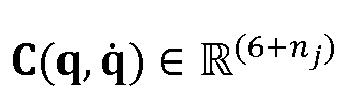
j ×6 I nj ×nj ] is a matrix for driving joints selected from all joints, f is a ground contact force,

FIG. 25 . - Based on the above, the movement control method for an underactuated robot provided in the embodiment of this application provides two alternative methods for determining the inclination angle acceleration reference value, to implement the control of the base portion and/or the vehicle wheel portion.
-
FIG. 25 is a schematic diagram of generalized coordinates of an underactuated robot according to an exemplary embodiment of this application. The joint angle qi and the driving torque τ i are marked around the joint. Double subscripts of q {·,·} and τ{·,·} respectively represent joint indexes of left and right legs. InFIG. 25 , only the connection and joints on the left leg are marked, and the right leg is symmetrical with the left leg for reference. In addition, for the sake of clarity, two joint angles q 11 and q 12 of a tail portion and the driving torques τ 7 and τ 8 are omitted inFIG. 25 . The controller of the underactuated robot may determine the control reference signal of the vehicle wheel portion and/or the base portion according to the whole-body dynamics model
- In all embodiments of the present disclosure, variable values of the driving torque τ, the ground friction f, and the closed-loop force λ that enable the whole-body dynamics model to have a minimum value may be determined through the argmin function, so as to determine the control reference signal of the vehicle wheel portion and/or the base portion. The argmin function may be expressed as:

- In the process of determining the variable values of the driving torque τ, the ground friction f, and the closed-loop force A, it is necessary to impose a conditional constraint on the underactuated robot.
- In all embodiments of the present disclosure, the whole-body dynamics model can be constrained by a dynamics model constraint condition, the dynamics model constraint condition including the inclination angle acceleration reference value. The dynamics model constraint condition is expressed as

- In addition to the constraint of the dynamics model constraint condition, the underactuated robot is further subject to at least one of the following constraints: a closed-loop link constraint; a constraint that no wheel slips or leaves the ground; and a friction constraint.
- The closed-loop link constraint may be expressed as J λ q̈ + J̇ λ q̇ = 0.


1 and J P2 are respectively Jacobian matrices of dots P1 and P2. Assuming that the wheel is purely rolling and contacts the ground, and no slip and slide occurs in radial and axial directions of the wheel, the constraint that no wheel slips or leaves the ground may be expressed as
- Step 2062: Control at least one of the base portion and the vehicle wheel portion to move according to torque information, so as to prevent the loaded object from falling from the base portion.
- For the loaded object being prevented from falling from the base portion, and the control of the base portion and/or the vehicle wheel portion, reference may be made to the foregoing contents, and details are not described again. After the torque information of the base portion and/or the vehicle wheel portion is determined, the controller of the underactuated robot transmits information (the information may be torque information) for implementing movement control to the driving motor of the underactuated robot, and the driving motor provides different driving forces according to the corresponding torque information to control the movement of the base portion and/or the vehicle wheel portion.
- For example,
step 2062 is similar to step 104, which may be used as reference, and details are not described again. - Based on the above, in the movement control method for an underactuated robot provided in the embodiment of this application, the inclination angle acceleration reference value of the base portion is determined according to the status information, and the controller of the underactuated robot inputs the inclination angle acceleration reference value into the whole-body dynamics model to obtain the control reference signal of the base portion and/or the vehicle wheel portion, thereby implementing the control of the base portion and/or the vehicle wheel portion.
- In all embodiments of the present disclosure, the embodiment of this application can provide two alternative methods for determining the inclination angle acceleration reference value. Optionally, the embodiment of this application provides an implementation of the whole-body dynamics model. It is to be understood that the foregoing contents are all illustrative examples, and any formula modification or increase or decrease of common variables according to the foregoing contents are included in the protection scope of this application.
- According to the foregoing content, the embodiment of this application further provides a method for determining the status information of the loaded object on the base portion. Based on
FIG. 15 ,FIG. 26 is a flowchart of a movement control method for an underactuated robot according to an exemplary embodiment of this application. - In all embodiments of the present disclosure, contact position coordinate transformation may be performed on the acquired information by acquiring position information of the loaded object on the base portion, or the position information and stress information, to determine the corresponding status information. Based on this, step 102 may be implemented as one of the following two sets of steps, which are specifically as follows.
- Step 1011: Acquire position information of a loaded object on a base portion.
- The position information of the loaded object on the base portion may be acquired in a plurality of ways.
- For example, the position information is sensed by a tactile sensor or a pressure sensor laid on the base portion. For another example, the position information is acquired through an action capture system. For another example, an image or a video on the base portion is acquired through a camera, and the position information is determined according to an image or video frame analysis technology.
- In all embodiments of the present disclosure,
step 1011 may be implemented by at least one of: acquiring the position information through a tactile sensor laid on the base portion; acquiring the position information through a pressure sensor laid on the base portion; acquiring the position information through an action capture system; and acquiring the position information of the loaded object on the base portion through a camera. - In a case that the position information is acquired by the tactile sensor, the tactile sensor may be composed of an m*n pressure sensor array. Optionally, a pressure sensor array is arranged on an upper surface of the base portion. The acquiring the position information through a tactile sensor laid on the base portion may be implemented by: determining the position information through a contact point of the loaded object on the pressure sensor array.
- In all embodiments of the present disclosure, the tactile sensor can include a pressure sensor array arranged in an m×n matrix, a length and a width of the m×n matrix matching the upper surface of the base portion, and m and n being positive integers. For example, if dimensions of the upper surface of the base portion are 40 cm*20 cm, one tactile sensor pressure acquisition point may be placed at a distance of 1 cm, and a pressure dot matrix on the upper surface of the base portion forms a corresponding 40*20 dot matrix. It is to be understood that in practical application, with the change of the dimension of the upper surface of the base portion, a difference among physical characteristics of the loaded object, a difference between an initial speed and a pressure detection range in the application scene, the delay of the bottom control of the motor, and the like, the spacing of a pressure dot matrix of the tactile sensor can be adaptively changed, and values of m and n may also be adaptively adjusted. The foregoing are only illustrative examples, and the values of m and n involved in this application are not specifically limited.
- In all embodiments of the present disclosure, a photographing area of the camera can cover the upper surface of the base portion in a case that the position information is acquired through the camera. The acquiring the position information of the loaded object on the base portion through a camera may be implemented by: determining the position information according to image information acquired by the camera.
- In all embodiments of the present disclosure, the position information can be identified by position coordinates of the loaded object on the base portion.
- Step 1021: Perform contact position coordinate transformation according to the position information to determine the status information.
- The contact position coordinate transformation is a process of converting the position information of the loaded object on the base portion into status information. The position information is acquired by the tactile sensor by way of example. A correspondence between a force signal changing unit and a position of the pressure sensor array on the upper surface of the base portion may be described through the contact position coordinate transformation. The relationship between the position of the upper surface of the base portion and the center of mass of the underactuated robot is known, and the contact point of the upper surface of the base portion and the loaded object may be obtained through coordinate conversion, which is equivalent to a position relationship between the loaded object and the center of mass being obtained.
- The position information is acquired by the tactile sensor by way of example. When an external force of the loaded object is applied to the corresponding pressure unit, the pressure value changes. Each unit can output a corresponding pressure value, but the pressure value of the unit that is not pressed is 0 or a very small noise value, and therefore it is necessary to filter out these small noises. The process may be regarded as a signal conditioning process.
- According to the different ways that the tactile sensor, the pressure sensor, the action capture system, or the camera acquires position information, the signal conditioning process is also different. Optionally, the signal conditioning includes but is not limited to using at least one of the following manners: averaging, calculation of force distribution, and threshold filtering.
- The averaging means that the pressure values within a certain range (such as 4*4 dot matrix or several dots in a circular region) are averaged, and the contact point between the loaded object and the underactuated robot is considered to contact the center of several dots. The calculation of force distribution means that the pressure value within a certain range is expressed in the form of distribution, and integration processing may be performed on the force value to obtain the magnitude and position distribution of the force, to determine the state of the loaded object. The threshold filtering means that because there is a certain probability that the pressure sensor is not detected, some noise may be detected without force, and a threshold is set accordingly. When the detected pressure value is below the threshold, it is considered that the sensor is not triggered.
- It is to be understood that the foregoing is an example of the signal conditioning process and does not constitute a limitation on the signal conditioning involved in this application.
- In all embodiments of the present disclosure, the position information may further be used for subsequent control. The rolling direction and speed of the loaded object on the base portion may be obtained by using a difference between positions of points on the base portion that contact the loaded object at two adjacent moments.
- The two adjacent moments may be regarded as two adjacent acquisition time points in a sampling period. The position information is acquired by the tactile sensor by way of example. It is assumed that the sampling period of the tactile sensor is 1,000 or 500 times a second, and two adjacent moments are two adjacent acquisition time points.
- Step 1012: Acquire position information and form information of a loaded object on a base portion.
- For example, the form information includes at least one piece of stress information, shape information, structure information, and physical information.
- The stress information refers to a stress value of the loaded object at a certain point on the base portion, and the stress information may be acquired in a plurality of manners. For example, the position information is sensed by a tactile sensor or a pressure sensor laid on the base portion. For another example, the position information is acquired through an action capture system.
- For example, related information such as the position, a displacement direction, a speed, and an acceleration of the loaded object on the base portion may be determined according to the stress information.
- The shape information is an external shape of the loaded object. For example, the shape information of the loaded object is a regular sphere or an irregular polyhedron. The structure information means that the composition structure of the loaded object includes but is not limited to components of the loaded object, a relative position relationship between components, and shapes and positions of components. The physical information is parameter information related to the physical characteristics of the loaded object, such as the mass and moment of inertia of the loaded object.
- The acquisition manners of shape information, structure information, and physical information are similar. For example, the information may be sensed by a tactile sensor or a pressure sensor, or may be acquired by a camera, or may be manually inputted into the controller of the underactuated robot by an operator.
- Step 1022: Perform contact position coordinate transformation according to the position information and the form information (for example, the stress information in all embodiments of the present disclosure) to determine the status information.
- For the contact position coordinate transformation, reference may be made to the foregoing content.
- For example,
step 1022 is similar to step 1021, which may be used as reference, and details are not described again. - In an optional implementation scenario, the controller of the underactuated robot issues an instruction to at least one auxiliary component of the tactile sensor, the pressure sensor, the action capture system, and the camera to acquire the position information or the position information and the stress information (as an example of the form information in all embodiments of the present disclosure) of the loaded object on the base portion. Subsequently, at least one auxiliary component reports the position information or the position information and the stress information of the loaded object on the base portion to the controller, and the controller determines the status information according to the position information or the position information and the stress information. Alternatively, the position information or the position information and the stress information may be processed by at least one auxiliary component to obtain status information, and then the status information is reported to the controller.
- Based on the above, the movement control method for an underactuated robot provided in the embodiment of this application provides an optional determination manner of the status information.
- According to the foregoing content, the underactuated robot is a wheel-legged robot and the loaded object is a sphere by way of example.
FIG. 27 is an overall control frame diagram of an underactuated robot according to an exemplary embodiment of this application. The wheel-legged robot includes a balance controller and a balance ball controller. The balance controller is configured to complete a cycle of balance angle reference to implement body balance of the wheel-legged robot. The balance ball controller is configured to implement a cycle of the balance ball reference, so as to achieve the goal of keeping the loaded object from falling from the base portion. - In all embodiments of the present disclosure, the wheel-legged robot can estimate the state through state signal collection, and determine a wheel rotation reference signal and other reference signals through the balance controller after the estimation is completed, which are used for controlling the movement of the vehicle wheel portion. The wheel rotation reference signal is used for completing a wheel balance task, and other reference signals are used for completing a wheel movement and steering task.
- In all embodiments of the present disclosure, the wheel-legged robot can perform contact position coordinate transformation through position information collection and/or stress information collection of the loaded object, and then determine a base attitude signal and other reference signals by using the balance ball controller through signal conditioning, which are used for controlling the movement of the base portion. The base attitude reference signal is used for completing a base attitude task, and other reference signals are used for completing a tail task. For example, the base attitude reference signal may be determined according to the inclination angle acceleration reference value of the base portion mentioned in the foregoing content, and is used for determining at least one of an inclination direction, an inclination angle, and an inclination speed of the base portion.
- According to the foregoing content, the overall movement of the wheel-legged robot is controlled by whole-body dynamics control, and the movement of the vehicle wheel portion and the base portion needs to satisfy the needs of the whole-body dynamics control.
- In the whole-body dynamics control, different control tasks are added according to the whole-body dynamics model, and considering physical constraints of the body, mapping between angular acceleration information of a joint space and a task space to each joint torque is established. By transmitting the joint torque to the corresponding driving motor of the wheel-legged robot, joint force control of the robot is realized, and then a form, an attitude, and a position of the robot in space are changed.
- For example, the control task includes a wheel balancing task, a wheel moving and steering task, a base attitude task, a tail task, a torque task, and an external force task. The wheel balancing task is to keep the attitude of an upper body of the robot balanced, and the wheel moving and steering task is a task that satisfies movement forward and backward of the robot and steering in a yaw direction. The base attitude task can realize the rotation of the base in pitch, roll, and yaw directions and the translation in x, y, and z directions. The tail task may be to place the tail portion to a specified position according to a given joint angle value corresponding to the tail portion. The torque task is generally to introduce the integral of a sum of squares of the torque of each joint motor with time into a cost function, so as to ensure that the value of each joint torque falls within a limited value range in the process of optimal solution. The external force task includes external forces in three directions corresponding to the contact points between two wheels and the ground respectively. The integral of a sum of squares of the external forces with time is introduced into a cost function, so as to ensure that values of the external forces all fall within a limited value range in the process of optimal solution.
- In all embodiments of the present disclosure, the whole-body dynamics model can be subject to a plurality of constraint conditions. The constraint conditions include a dynamics model constraint condition, a closed-loop link constraint, a constraint that no wheel slips or leaves the ground, and a friction constraint.
- Based on the above, the movement control method for an underactuated robot provided in the embodiment of this application provides an optional determination manner of the status information. In addition, the embodiment of this application further gives an overall control framework using the wheel-legged robot as an example.
- For example, an embodiment of this application further provides an underactuated robot.
- For example, the underactuated robot includes a vehicle wheel portion and a base portion connected to the vehicle wheel portion, the base portion being configured to bear a loaded object; a controller being arranged in that underactuated robot, the controller being configured to control the underactuated robot to: control, according to status information of the loaded object on the base portion, at least one of the base portion and the vehicle wheel portion to move, so as to prevent the loaded object from falling from the base portion. The controller may be arranged according to the actual needs, which is not limited in this application. All underactuated robots that can achieve the goal of keeping the loaded object from falling from the base portion through the movement control of the controller fall within the protection scope of this application. The movement control of the underactuated robot has been described in detail in the foregoing contents, which may be used as a reference, and details are not described again.
- In all embodiments of the present disclosure, a pressure sensor array can be arranged on an upper surface of the base portion. The pressure sensor array is configured to acquire position information of the loaded object on the base portion. The density of the pressure sensor array may be limited according to the actual needs. For details, reference is made to the foregoing part, and details are not described again. For example, the tactile sensor includes a pressure sensor array arranged in an m×n matrix, a length and a width of the m×n matrix matching the upper surface of the base portion, and m and n being positive integers.
- In all embodiments of the present disclosure, the underactuated robot can further include a camera. The camera is configured to acquire the position information of the loaded object on the base portion.
- In all embodiments of the present disclosure, the camera can be arranged on the base portion, and a photographing area of the camera can cover the upper surface of the base portion.
- Apparatus embodiments of this application are described below. For details that are not described in detail in the apparatus embodiments, reference may be made to the corresponding records in the foregoing method embodiments, and details are not described herein again.
-
FIG. 28 is a schematic diagram of a movement control apparatus of an underactuated robot according to an exemplary embodiment of this application. The apparatus includes: adetermination module 2820, configured to determine status information of a loaded object on a base portion; and acontrol module 2840, configured to control, according to the determined status information, at least one of the base portion and a vehicle wheel portion to move, so as to prevent the loaded object from falling from the base portion. - In all embodiments of the present disclosure, the vehicle wheel portion can include a leg portion and a wheel portion. The
control module 2840 is configured to control the wheel portion to move and the base portion to move inclinedly according to the status information, so as to maintain body balance of the underactuated robot and prevent the loaded object from falling from the base portion, the inclined movement of the base portion and the movement of the wheel portion interacting with each other through stretching/retraction of the leg portion. - In all embodiments of the present disclosure, the
control module 2840 can be configured to control the vehicle wheel portion to move and the base portion to move inclinedly according to the status information in a case that the loaded object and/or the underactuated robot is subject to external interference, so as to maintain body balance of the underactuated robot and prevent the loaded object from falling from the base portion. - In all embodiments of the present disclosure, the external interference can include at least one of the following: a center of the loaded object is subject to external interference; a part of the loaded object other than the center is subject to external interference; a center of mass of the loaded object is subject to external interference; a circumferential side of the center of mass of the loaded object is subject to external interference; the base portion is subject to external interference; and the vehicle wheel portion is subject to external interference.
- In all embodiments of the present disclosure, the
control module 2840 can be configured to: control the wheel portion to move forward in a first direction according to the status information in a case that the loaded object moves on the base portion in the first direction; or control one side of the base portion close to the first direction to lift and the other side of the base portion away from the first direction to fall according to the status information in a case that the loaded object moves in the first direction; or control the wheel portion to move forward in the first direction and controlling the one side of the base portion close to the first direction to lift and the other side of the base portion away from the first direction to fall according to the status information in a case that the loaded object moves in the first direction. - In all embodiments of the present disclosure, the
control module 2840 can be configured to: determine an inclination angle acceleration reference value of the base portion according to the status information; and control the at least one of the base portion and the vehicle wheel portion to move according to the inclination angle acceleration reference value and a whole-body dynamics model of the underactuated robot. - In all embodiments of the present disclosure, the status information can include: a displacement of a contact point of the loaded object on the base portion in a target direction relative to a center of mass of the underactuated robot on the base portion, and a movement speed of the contact point on the base portion in the target direction. The
control module 2840 is configured to determine a first inclination angle acceleration reference value of the base portion by using a difference between the displacement and a preset displacement and a difference between the movement speed and a preset movement speed as inputs of a PID controller. - In all embodiments of the present disclosure, the status information can include: a displacement of a contact point of the loaded object on the base portion in a target direction relative to the center of mass of the underactuated robot on the base portion, a movement speed of the contact point on the base portion in the target direction, an inclination angle of the base portion, and an inclination angle speed of the base portion. The
control module 2840 is configured to determine a second inclination angle acceleration reference value of the base portion by using a difference between the displacement and a preset displacement, a difference between the movement speed and a preset movement speed, a difference between the inclination angle and a preset inclination angle, and a difference between the inclination angle speed and a preset inclination angle speed as inputs of a PID controller. - In all embodiments of the present disclosure, at least one of the preset displacement, the preset movement speed, the preset inclination angle, and the preset inclination angle speed can be determined according to structural features of the underactuated robot.
- In all embodiments of the present disclosure, the
control module 2840 can be configured to: determine torque information of the base portion and/or the vehicle wheel portion by using the inclination angle acceleration reference value and the whole-body dynamics model of the underactuated robot as inputs of a PID controller; and control the at least one of the base portion and the vehicle wheel portion to move according to the torque information. - In all embodiments of the present disclosure, the
control module 2840 can be configured to: construct the whole-body dynamics model based on a driving torque, a ground friction, and a closed-loop force of the underactuated robot; and substitute the inclination angle acceleration reference value into the whole-body dynamics model to determine the torque information through the PID controller. Optionally, the whole-body dynamics model is constrained by a dynamics model constraint condition, the dynamics model constraint condition including the inclination angle acceleration reference value. - In all embodiments of the present disclosure, the
determination module 2820 can be configured to acquire position information of a loaded object on a base portion; and perform contact position coordinate transformation according to the position information to determine the status information. - In all embodiments of the present disclosure, the
determination module 2820 can be configured to: acquire the position information through a tactile sensor laid on the base portion; or acquire the position information through a pressure sensor laid on the base portion; or acquire the position information through an action capture system; or acquire the position information of the loaded object on the base portion through a camera. - In all embodiments of the present disclosure, a pressure sensor array can be arranged on an upper surface of the base portion. The
determination module 2820 is configured to determine the position information through a contact point of the loaded object on the pressure sensor array. Optionally, the tactile sensor includes a pressure sensor array arranged in an m×n matrix, a length and a width of the m×n matrix matching the upper surface of the base portion, and m and n being positive integers. - In all embodiments of the present disclosure, a photographing area of the camera can cover the upper surface of the base portion. The
determination module 2820 is configured to determine the position information according to image information acquired by the camera. - In all embodiments of the present disclosure, the
determination module 2820 can be configured to: acquire the position information and form information of the loaded object on the base portion, the form information including at least one piece of stress information, shape information, structure information, and physical information; and perform contact position coordinate transformation according to the position information and the form information to determine the status information. - For the apparatus provided in the foregoing embodiments, only division of the functional modules is described by using examples. In practical application, the functions are completed by different functional modules as required. That is to say, an internal structure of the device is divided into different functional modules to complete all or a part of the functions described above. In addition, the apparatus provided in the foregoing embodiments and the method embodiments in the foregoing content fall within a same conception. For details of a specific implementation process, refer to the method embodiments. Details are not described herein again.
-
FIG. 29 is a structural block diagram of anelectronic device 2900 according to an exemplary embodiment of this application. - The
electronic device 2900 may be a portable mobile terminal, such as an electronic device, a smartphone, a tablet computer, a Moving Picture Experts Group Audio Layer III (MP3) player, a Moving Picture Experts Group Audio Layer IV (MP4) player, a notebook computer, or a desktop computer that is configured to implement the control of the underactuated robot. Theelectronic device 2900 may further be referred to as another name such as user equipment, a portable terminal, a laptop terminal, a desktop terminal, or the like. In the embodiment of this application, theelectronic device 2900 may be implemented as a control device part in a robot. - The
electronic device 2900 generally includes aprocessor 2901 and amemory 2902. - The
processor 2901 may include one or more processing cores, such as a 4-core processor, an 8-core processor, and the like. Theprocessor 2901 may be implemented in at least one hardware form of a digital signal processor (DSP), a field-programmable gate array (FPGA), and a programmable logic array (PLA). Theprocessor 2901 may also include a main processor and a coprocessor. The main processor is a processor configured to process data in an awake state, and is also referred to as a central processing unit (CPU). The coprocessor is a low power consumption processor configured to process the data in a standby state. In some embodiments, theprocessor 2901 may be integrated with a graphics processing unit (GPU). The GPU is configured to render and draw content that needs to be displayed on a display screen. In some embodiments, theprocessor 2901 may further include an artificial intelligence (AI) processor. The AI processor is configured to process computing operations related to machine learning. - The
memory 2902 may include one or more computer-readable storage media. The computer-readable storage medium may be non-transient. Thememory 2902 may further include a high-speed random access memory and a nonvolatile memory, for example, one or more disk storage devices or flash storage devices. In some embodiments, the non-transient computer-readable storage medium in thememory 2902 is configured to store at least one instruction, the at least one instruction being configured to be executed by theprocessor 2901 to implement the movement control method for an underactuated robot provided in the method embodiments of this application. - In all embodiments of the present disclosure, the
electronic device 2900 may further optionally include aperipheral device interface 2903 and at least one peripheral device. Theprocessor 2901, thememory 2902, and theperipheral device interface 2903 may be connected through a bus or a signal line. Each peripheral device may be connected to theperipheral device interface 2903 through a bus, a signal line, or a circuit board. Specifically, the peripheral device includes: at least one of a radio frequency (RF)circuit 2904, adisplay screen 2905, acamera assembly 2906, anaudio circuit 2907, and apower supply 2908. - The
peripheral device interface 2903 may be configured to connect the at least one peripheral device related to input/output (I/O) to theprocessor 2901 and thememory 2902. In some embodiments, theprocessor 2901, thememory 2902, and theperipheral device interface 2903 are integrated on the same chip or circuit board. In some other embodiments, any or both of theprocessor 2901, thememory 2902, and theperipheral device interface 2903 may be implemented on an independent chip or circuit board, which is not limited in this embodiment. - The
RF circuit 2904 is configured to receive and transmit an RF signal, which is also referred to as an electromagnetic signal. TheRF circuit 2904 communicates with a communication network and other communication devices through the electromagnetic signal. TheRF circuit 2904 converts an electric signal into an electromagnetic signal for transmission, or converts a received electromagnetic signal into an electric signal. Optionally, theRF circuit 2904 includes: an antenna system, an RF transceiver, one or more amplifiers, a tuner, an oscillator, a digital signal processor, a codec chip set, a subscriber identity module card, and the like. TheRF circuit 2904 may communicate with other terminals by using at least one wireless communication protocol. The wireless communication protocol includes but is not limited to: the World Wide Web, a metropolitan area network, Intranet, various generations of mobile communication networks (2G, 3G, 4G, and 5G), a wireless local area network, and/or a wireless fidelity (Wi-Fi) network. In some embodiments, theRF circuit 2904 may further include a near field communication (NFC)-related circuit, which is not limited in this application. - The
display screen 2905 is configured to display a user interface (UI). The UI may include a graph, texts, an icon, a video, and any combination thereof. In a case that thedisplay screen 2905 is a touch display screen, thedisplay screen 2905 further has the capability of collecting a touch signal on or above a surface of thedisplay screen 2905. The touch signal may be inputted to theprocessor 2901 as a control signal for processing. In this case, thedisplay screen 2905 may be further configured to provide a virtual button and/or a virtual keyboard, which are/is also referred to as a soft button and/or a soft keyboard. In some embodiments, onedisplay screen 2905 may be arranged on a front panel of theelectronic device 2900. In some other embodiments, at least twodisplay screens 2905 may be respectively arranged on different surfaces of theelectronic device 2900 or may be folded. In some other embodiments, thedisplay screen 2905 may be a flexible display screen arranged on a curved surface or a folding surface of theelectronic device 2900. Thedisplay screen 2905 may be even arranged as a non-rectangular irregular figure, that is, a special-shaped screen. Thedisplay screen 2905 may be manufactured by using a liquid crystal display (LCD), an organic light-emitting diode (OLED), or the like. - The
camera assembly 2906 is configured to collect an image or a video. Optionally, thecamera assembly 2906 includes a front camera and a rear camera. Generally, the front camera is arranged on the front panel of the terminal, and the rear camera is arranged on the back of the terminal. In some embodiments, at least two rear cameras are arranged, which are respectively any of a main camera, a depth-of-field camera, a wide-angle camera, and a telephoto camera, to achieve background blurring through fusion of the main camera and the depth-of-field camera, panoramic shooting and virtual reality (VR) shooting through fusion of the main camera and the wide-angle camera, or other fusion shooting functions. In some embodiments, thecamera assembly 2906 may further include a flashlight. The flashlight may be a single-color-temperature flashlight or a dual-color-temperature flashlight. The dual-color-temperature flashlight is a combination of a warm flashlight and a cold flashlight, which may be used for light compensation at different color temperatures. - The
audio circuit 2907 may include a microphone and a speaker. The microphone is configured to collect sound waves of a user and an environment, and convert the sound waves into electrical signals and input the electrical signals to theprocessor 2901 for processing, or input the electrical signals to theRF circuit 2904 to implement voice communication. For the purpose of stereo collection or noise reduction, a plurality of microphones may be respectively arranged at different parts of theelectronic device 2900. The microphone may be further an array microphone or an omnidirectional acquisition microphone. The speaker is configured to convert the electrical signal from theprocessor 2901 or theRF circuit 2904 into sound waves. The speaker may be a conventional film speaker, or may be a piezoelectric ceramic speaker. In a case that the speaker is the piezoelectric ceramic speaker, the speaker not only can convert an electric signal into the sound wave audible to a human being, but also can convert the electric signal into the sound wave inaudible to a human being, for ranging and other purposes. In some embodiments, theaudio circuit 2907 may further include a headphone jack. - The
power supply 2908 is configured to supply power to assemblies in theelectronic device 2900. Thepower supply 2908 may be an alternating current battery, a direct current battery, a disposable battery, or a rechargeable battery. When thepower supply 2908 includes a rechargeable battery, the rechargeable battery may be a wired rechargeable battery or a wireless rechargeable battery. The wired rechargeable battery is a battery charged through a wired circuit, and the wireless rechargeable battery is a battery charged through a wireless coil. The rechargeable battery may be further configured to support a fast charging technology. - In all embodiments of the present disclosure, the
electronic device 2900 can further include one ormore sensors 2909. The one ormore sensors 2909 include but are not limited to: anacceleration sensor 2910, agyroscope sensor 2911, apressure sensor 2912, anoptical sensor 2913, and aproximity sensor 2914. - The
acceleration sensor 2910 may detect a magnitude of acceleration on three coordinate axes of a coordinate system established with theelectronic device 2900. For example, theacceleration sensor 2910 may be configured to detect components of acceleration of gravity on the three coordinate axes. Theprocessor 2901 may control, according to a gravity acceleration signal collected by theacceleration sensor 2910, thedisplay screen 2905 to display the UI in a landscape view or a portrait view. Theacceleration sensor 2910 may be further configured to collect movement data of a game or a user. - The
gyroscope sensor 2911 may detect a body direction and a rotation angle of theelectronic device 2900. Thegyroscope sensor 2911 may cooperate with theacceleration sensor 2910 to collect a 3D action performed by a user on theelectronic device 2900. Theprocessor 2901 may implement the following functions according to the data collected by the gyroscope sensor 2911: movement sensing (for example, changing the UI based on a tilt operation of the user), image stabilization during shooting, game control, and inertial navigation. - The
pressure sensor 2912 may be arranged at a side frame of theelectronic device 2900 and/or a lower layer of thedisplay screen 2905. In a case that thepressure sensor 2912 is arranged at the side frame of theelectronic device 2900, a grip signal of the user on theelectronic device 2900 may be detected, and theprocessor 2901 may perform left-right hand recognition or a shortcut operation according to the grip signal collected by thepressure sensor 2912. In a case that thepressure sensor 2912 is arranged at the lower layer of thedisplay screen 2905, theprocessor 2901 controls an operable control on the UI interface according to a pressure operation performed by the user on thedisplay screen 2905. The operable control includes at least one of a button control, a scroll-bar control, an icon control, and a menu control. - The
optical sensor 2913 is configured to collect ambient light intensity. In an embodiment, theprocessor 2901 may control display brightness of thedisplay screen 2905 according to the ambient light intensity collected by theoptical sensor 2913. Specifically, in a case that the ambient light intensity is relatively high, the display brightness of thedisplay screen 2905 is increased. In a case that the ambient light intensity is relatively low, the display brightness of thedisplay screen 2905 is reduced. In another embodiment, theprocessor 2901 may further dynamically adjust a shooting parameter of thecamera assembly 2906 according to the ambient light intensity collected by theoptical sensor 2913. - The
proximity sensor 2914, also referred to as a distance sensor, is usually arranged on the front panel of theelectronic device 2900. Theproximity sensor 2914 is configured to acquire a distance between the user and a front side of theelectronic device 2900. In an embodiment, in a case that theproximity sensor 2914 detects that the distance between the user and the front side of theelectronic device 2900 gradually becomes smaller, theprocessor 2901 controls thedisplay screen 2905 to be switched from a screen-on state to a screen-off state. In a case that theproximity sensor 2914 detects that the distance between the user and the front side of theelectronic device 2900 gradually becomes larger, theprocessor 2901 controls thedisplay screen 2905 to be switched from the screen-off state to the screen-on state. - A person skilled in the art may understand that the structure shown in
FIG. 29 does not constitute a limitation on theelectronic device 2900, and may include more or fewer assemblies than that shown in the drawing, or combine some assemblies, or adopt different assembly arrangements. -
FIG. 30 is a schematic structural block diagram of an underactuated robot according to an embodiment of this application. As shown inFIG. 30 , the underactuated robot in this embodiment may include: one ormore processors 3001; and one ormore sensors 3002, one ormore motors 3003, and amemory 3004. Theprocessor 3001, thesensor 3002, themotor 3003, and thememory 3004 are connected through abus 3005. Thememory 3004 is configured to store a computer program. The computer program includes a program instruction. Theprocessor 3001 is configured to execute the program instruction stored in thememory 3004. - The
processor 3001 may be a central processing unit (CPU). Theprocessor 3001 may further include a hardware chip. The foregoing hardware chip may be an application-specific integrated circuit (ASIC), a programmable logic device (PLD), or the like. The PLD may be a field-programmable gate array (FPGA), a generic array logic (GAL), and the like. Theprocessor 3001 may also be a combination of the foregoing structures. In some embodiments, theprocessor 3001 may be implemented as an internal controller of the underactuated robot involved in the foregoing content. - The
sensor 3002 is configured to acquire status data related to the movement control of the underactuated robot, such as position information and/or stress information involved in the foregoing contents. - The
motor 3003 is configured to control the movement of the underactuated robot and complete the movement action. Optionally, themotor 3003 includes a joint motor and a wheel motor of the underactuated robot. - The
memory 3004 may include a volatile memory such as a random-access memory (RAM). Thememory 3004 may also include a non-volatile memory such as a flash memory, a solid-state drive (SSD), or the like. Optionally, thememory 3004 may further include a combination of the foregoing types of memories. - In the embodiment of this application, the
memory 3004 is configured to store a computer program. The computer program includes a program instruction. Theprocessor 3001 is configured to execute the program instruction stored in thememory 3004 to implement the movement control method for an underactuated robot given in the foregoing content. - An embodiment of this application further provides a computer device. The computer device includes a processor, the processor being configured to: determine status information of a loaded object on a base portion; and control, according to the determined status information, at least one of the base portion and the vehicle wheel portion to move, so as to prevent the loaded object from falling from the base portion.
- An embodiment of this application further provides a computer-readable storage medium, the storage medium storing a computer program, the computer program being executed by a processor to implement the movement control method for an underactuated robot as described above.
- An embodiment of this application further provides a chip, including a programmable logic circuit and/or program instructions, the chip, when run, being configured to implement the movement control method for an underactuated robot as described above.
- An embodiment of this application further provides a computer program product, including computer instructions stored in a computer-readable storage medium, a processor reading the computer instructions from the computer-readable storage medium and executing the computer instructions, to implement the movement control method for an underactuated robot as described above.
- In this application, it is to be understood that the terms such as "first" and "second" are used only for the purpose of description, and not to be understood as indicating or implying the relative importance or implicitly specifying a number of indicated technical features.
- An optional embodiment of this application may be formed by using any combination of all the foregoing optional technical solutions, and the details are not described herein again.
- The foregoing descriptions are merely optional embodiments of this application, but are not intended to limit this application. Any modification, equivalent replacement, or improvement made within the spirit and principle of this application shall fall within the protection scope of this application.
Claims (24)
- A movement control method for an underactuated robot, the method being executable by a controller of the underactuated robot, the underactuated robot comprising a vehicle wheel portion and a base portion connected to the vehicle wheel portion, a loaded object being placed on the base portion, and the method comprising:determining status information of the loaded object on the base portion; andcontrolling, according to the determined status information, at least one of the base portion and the vehicle wheel portion to move, so as to prevent the loaded object from falling from the base portion.
- The method according to claim 1, wherein the vehicle wheel portion comprises a leg portion and a wheel portion, and the controlling, according to the determined status information, at least one of the base portion and the vehicle wheel portion to move, so as to prevent the loaded object from falling from the base portion comprises:
controlling the wheel portion to move and the base portion to move inclinedly according to the status information, so as to maintain body balance of the underactuated robot and prevent the loaded object from falling from the base portion, the inclined movement of the base portion and the movement of the wheel portion interacting with each other through stretching/retraction of the leg portion. - The method according to claim 2, wherein the controlling the wheel portion to move and the base portion to move inclinedly according to the status information, so as to maintain body balance of the underactuated robot and prevent the loaded object from falling from the base portion comprises:
controlling the wheel portion to move and the base portion to move inclinedly according to the status information in a case that the loaded object and/or the underactuated robot is subject to external interference, so as to maintain body balance of the underactuated robot and prevent the loaded object from falling from the base portion. - The method according to claim 3, wherein the external interference comprises at least one of the following:a center of the loaded object is subject to external interference;a part of the loaded object other than the center is subject to external interference;a center of mass of the loaded object is subject to external interference;a circumferential side of the center of mass of the loaded object is subject to external interference;the base portion is subject to external interference; andthe vehicle wheel portion is subject to external interference.
- The method according to claim 2, wherein the controlling the vehicle wheel portion to move and the base portion to move inclinedly according to the status information comprises:controlling the wheel portion to move forward in a first direction according to the status information in a case that the loaded object moves on the base portion in the first direction; orcontrolling one side of the base portion close to the first direction to lift and the other side of the base portion away from the first direction to fall according to the status information in a case that the loaded object moves in the first direction; orcontrolling the wheel portion to move forward in the first direction and controlling the one side of the base portion close to the first direction to lift and the other side of the base portion away from the first direction to fall according to the status information in a case that the loaded object moves in the first direction.
- The method according to any one of claims 1 to 5, wherein the controlling, according to the determined status information, at least one of the base portion and the vehicle wheel portion to move comprises:determining an inclination angle acceleration reference value of the base portion according to the status information; andcontrolling the at least one of the base portion and the vehicle wheel portion to move according to the inclination angle acceleration reference value and a whole-body dynamics model of the underactuated robot.
- The method according to claim 6, wherein the status information comprises a displacement of a contact point of the loaded object on the base portion in a target direction relative to a center of mass of the underactuated robot on the base portion and a movement speed of the contact point on the base portion in the target direction; and
the determining an inclination angle acceleration reference value of the base portion according to the status information comprises:
determining a first inclination angle acceleration reference value of the base portion by using a difference between the displacement and a preset displacement and a difference between the movement speed and a preset movement speed as inputs of a closed-loop proportional-integral-derivative PID controller. - The method according to claim 6, wherein the status information comprises a displacement of a contact point of the loaded object on the base portion in a target direction relative to the center of mass of the underactuated robot on the base portion, a movement speed of the contact point on the base portion in the target direction, an inclination angle of the base portion, and an inclination angle speed of the base portion; and
the determining an inclination angle acceleration reference value of the base portion according to the status information comprises:
determining a second inclination angle acceleration reference value of the base portion by using a difference between the displacement and a preset displacement, a difference between the movement speed and a preset movement speed, a difference between the inclination angle and a preset inclination angle, and a difference between the inclination angle speed and a preset inclination angle speed as inputs of a closed-loop PID controller. - The method according to claim 7 or 8, wherein at least one of the preset displacement, the preset movement speed, the preset inclination angle, and the preset inclination angle speed is determined according to structural features of the underactuated robot.
- The method according to claim 6, wherein the controlling the at least one of the base portion and the vehicle wheel portion to move according to the inclination angle acceleration reference value and a whole-body dynamics model of the underactuated robot comprises:determining torque information of the base portion and/or the vehicle wheel portion by using the inclination angle acceleration reference value and the whole-body dynamics model of the underactuated robot as inputs of a closed-loop PID controller; andcontrolling the at least one of the base portion and the vehicle wheel portion to move according to the torque information.
- The method according to claim 10, wherein the determining torque information of the base portion and/or the vehicle wheel portion by using the inclination angle acceleration reference value and the whole-body dynamics model of the underactuated robot as inputs of a PID controller comprises:constructing the whole-body dynamics model based on a driving torque, a ground friction, and a closed-loop force of the underactuated robot; andsubstituting the inclination angle acceleration reference value into the whole-body dynamics model to determine the torque information through the PID controller.
- The method according to claim 11, wherein the whole-body dynamics model is constrained by a dynamics model constraint condition, the dynamics model constraint condition comprising the inclination angle acceleration reference value.
- The method according to any one of claims 1 to 5, wherein the determining status information of the loaded object on the base portion comprises:acquiring position information of the loaded object on the base portion; andperforming contact position coordinate transformation according to the position information to determine the status information.
- The method according to claim 13, wherein the acquiring position information of the loaded object on the base portion comprises at least one of:acquiring the position information through a tactile sensor laid on the base portion;acquiring the position information through a pressure sensor laid on the base portion;acquiring the position information through an action capture system; andacquiring the position information of the loaded object on the base portion through a camera.
- The method according to claim 14, wherein a pressure sensor array is arranged on an upper surface of the base portion; and
the acquiring the position information through a tactile sensor laid on the base portion comprises:
determining the position information through a contact point of the loaded object on the pressure sensor array. - The method according to claim 15, wherein the tactile sensor comprises a pressure sensor array arranged in an m×n matrix, a length and a width of the m×n matrix matching the upper surface of the base portion, and m and n being positive integers.
- The method according to claim 14, wherein a photographing area of the camera covers the upper surface of the base portion; and
the acquiring the position information of the loaded object on the base portion through a camera comprises:
determining the position information according to image information acquired by the camera. - The method according to any one of claims 1 to 5, wherein the determining status information of the loaded object on the base portion comprises:acquiring position information of the loaded object on the base portion and form information of the loaded object, the form information comprising at least one piece of stress information, shape information, structure information, and physical information; andperforming contact position coordinate transformation according to the position information and the form information to determine the status information.
- An underactuated robot, comprising a vehicle wheel portion and a base portion connected to the vehicle wheel portion, the base portion being configured to bear a loaded object; and
a controller being arranged in the underactuated robot, the controller being configured to control the underactuated robot to: control, according to status information of the loaded object on the base portion, at least one of the base portion and the vehicle wheel portion to move, so as to prevent the loaded object from falling from the base portion. - A movement control apparatus for an underactuated robot, the apparatus comprising:a determination module, configured to determine status information of a loaded object on a base portion; anda control module, configured to control, according to the determined status information, at least one of the base portion and a vehicle wheel portion to move, so as to prevent the loaded object from falling from the base portion.
- A computer device, comprising a processor,the processor being configured to: determine status information of a loaded object on a base portion; andcontrol, according to the determined status information, at least one of the base portion and a vehicle wheel portion to move, so as to prevent the loaded object from falling from the base portion.
- A computer-readable storage medium, storing a computer program, the computer program being executed by a processor to implement the movement control method for an underactuated robot according to any one of claims 1 to 18.
- A chip, comprising a programmable logic circuit and/or program instructions, the chip, when run, being configured to implement the movement control method for an underactuated robot according to any one of claims 1 to 18.
- A computer program product, comprising computer instructions stored in a computer-readable storage medium, a processor reading the computer instructions from the computer-readable storage medium and executing the computer instructions, to implement the movement control method for an underactuated robot according to any one of claims 1 to 18.
Applications Claiming Priority (2)
| Application Number | Priority Date | Filing Date | Title |
|---|---|---|---|
| CN202210015856.0A CN116442208B (en) | 2022-01-07 | 2022-01-07 | Motion control method of underactuated system robot and underactuated system robot |
| PCT/CN2022/129831 WO2023130824A1 (en) | 2022-01-07 | 2022-11-04 | Motion control method for under-actuated system robot, and under-actuated system robot |
Publications (2)
| Publication Number | Publication Date |
|---|---|
| EP4393654A1 true EP4393654A1 (en) | 2024-07-03 |
| EP4393654A4 EP4393654A4 (en) | 2025-03-26 |
Family
ID=87073028
Family Applications (1)
| Application Number | Title | Priority Date | Filing Date |
|---|---|---|---|
| EP22918276.1A Pending EP4393654A4 (en) | 2022-01-07 | 2022-11-04 | Motion control method for under-actuated system robot, and under-actuated system robot |
Country Status (5)
| Country | Link |
|---|---|
| US (1) | US12583099B2 (en) |
| EP (1) | EP4393654A4 (en) |
| JP (1) | JP7758271B2 (en) |
| CN (1) | CN116442208B (en) |
| WO (1) | WO2023130824A1 (en) |
Families Citing this family (7)
| Publication number | Priority date | Publication date | Assignee | Title |
|---|---|---|---|---|
| CN111776106B (en) * | 2020-08-12 | 2024-02-23 | 腾讯科技(深圳)有限公司 | Mechanical leg and wheeled mobile device |
| US12415267B2 (en) * | 2023-05-30 | 2025-09-16 | Siemens Aktiengesellschaft | Synthesizing machine learning-based controllers for underactuated robotic manipulators |
| CN117444934B (en) * | 2023-12-25 | 2024-03-26 | 国仪大为(北京)智能科技有限公司 | Rehabilitation accompanying deformation robot |
| CN118990516A (en) * | 2024-10-21 | 2024-11-22 | 北京东方昊为工业装备有限公司 | Method for controlling movement track of industrial robot |
| CN119472651B (en) * | 2024-10-25 | 2026-02-17 | 江西云杉智能科技有限公司 | AGV control method, AGV control device and AGV |
| CN119749738B (en) * | 2024-12-31 | 2025-11-07 | 同济大学 | Design and control method of wheel leg balance robot capable of actively jumping |
| CN120886286B (en) * | 2025-08-22 | 2026-01-30 | 沈阳工程学院 | Self-adaptive grabbing device for special-shaped curved surface workpiece |
Family Cites Families (18)
| Publication number | Priority date | Publication date | Assignee | Title |
|---|---|---|---|---|
| JP2004021693A (en) * | 2002-06-18 | 2004-01-22 | Sanyo Electric Co Ltd | Transfer robot table angle control method |
| JP2006123854A (en) * | 2004-11-01 | 2006-05-18 | Matsushita Electric Ind Co Ltd | Luggage transport robot |
| JP2010225139A (en) * | 2009-02-27 | 2010-10-07 | Toshiba Corp | Mobile equipment |
| AU2015230123A1 (en) | 2014-03-12 | 2016-09-22 | Kil Bong Song | Centrifugal propulsion apparatus and ship having same |
| CN104898669B (en) | 2015-04-30 | 2019-01-11 | 广东虚拟现实科技有限公司 | A method and system for virtual reality walking control based on inertial sensors |
| US20180236668A1 (en) * | 2015-10-27 | 2018-08-23 | Panasonic Intellectual Property Management Co., Lt | Carrier device |
| CN106428284B (en) | 2016-08-30 | 2018-11-02 | 陆任行 | Polypody independently moves toter |
| CN107499393B (en) * | 2017-08-04 | 2020-11-13 | 歌尔科技有限公司 | Double round self-balancing robot |
| CN207903351U (en) * | 2017-12-28 | 2018-09-25 | 广州赛特智能科技有限公司 | A kind of merchandising machine people of autonomous control balance |
| US10821602B2 (en) * | 2017-12-28 | 2020-11-03 | Aeolus Robotics Corporation Limited | Carrier for robot and robot having the same |
| CN109099898A (en) * | 2018-08-17 | 2018-12-28 | 北京理工大学 | A kind of mobile service system based on self-stabilization platform |
| GB2586217B (en) * | 2019-08-01 | 2022-06-15 | Arrival Ltd | A system and method for operating an autonomous mobile robot based on payload sensing |
| CN110764413B (en) * | 2019-10-29 | 2020-09-29 | 中国科学院自动化研究所 | Self-stabilizing control method, system and device for wheel-legged robot |
| CN111085446B (en) * | 2020-01-03 | 2023-07-18 | 华南理工大学 | A fast-response and balanced logistics robot and its control method |
| CN112975978B (en) | 2021-03-05 | 2022-07-29 | 深圳市优必选科技股份有限公司 | Multi-legged robot load balancing method, device and multi-legged robot |
| CN113753150B (en) * | 2021-05-31 | 2024-01-12 | 腾讯科技(深圳)有限公司 | Control method, device and equipment of wheel leg type robot and readable storage medium |
| DE102022202045B4 (en) * | 2022-02-28 | 2024-12-05 | Fraunhofer-Gesellschaft zur Förderung der angewandten Forschung eingetragener Verein | Devices and methods for and with mobile platforms for the transport of cargo |
| CN116812036A (en) * | 2022-03-22 | 2023-09-29 | 台达电子工业股份有限公司 | Mobile carrier and stabilizing method thereof |
-
2022
- 2022-01-07 CN CN202210015856.0A patent/CN116442208B/en active Active
- 2022-11-04 EP EP22918276.1A patent/EP4393654A4/en active Pending
- 2022-11-04 JP JP2024514490A patent/JP7758271B2/en active Active
- 2022-11-04 WO PCT/CN2022/129831 patent/WO2023130824A1/en not_active Ceased
-
2023
- 2023-07-11 US US18/350,339 patent/US12583099B2/en active Active
Also Published As
| Publication number | Publication date |
|---|---|
| US20230347501A1 (en) | 2023-11-02 |
| CN116442208B (en) | 2024-12-13 |
| JP2024532535A (en) | 2024-09-05 |
| EP4393654A4 (en) | 2025-03-26 |
| US12583099B2 (en) | 2026-03-24 |
| JP7758271B2 (en) | 2025-10-22 |
| WO2023130824A1 (en) | 2023-07-13 |
| CN116442208A (en) | 2023-07-18 |
Similar Documents
| Publication | Publication Date | Title |
|---|---|---|
| EP4393654A1 (en) | Motion control method for under-actuated system robot, and under-actuated system robot | |
| US12594804B2 (en) | Mobile robot motion control method and mobile robot | |
| CN116991090B (en) | Motion swinging method and device of robot, storage medium and product | |
| CN113752250A (en) | Method and device for controlling robot joint, robot and storage medium | |
| CN110785601A (en) | Control method of handheld cloud deck and handheld cloud deck | |
| WO2024066868A1 (en) | Robot control method and apparatus, and robot, computer-readable storage medium and computer program product | |
| CN114764241A (en) | Motion state control method, device and equipment and readable storage medium | |
| US20230381964A1 (en) | Method and apparatus for controlling wheel-legged robot | |
| CN114791729B (en) | Control method, device, equipment and readable storage medium of wheeled robot | |
| CN115480560B (en) | Control method and device for motion state, wheel-leg robot and storage medium | |
| CN116991153B (en) | Motion control methods for mobile robots and mobile robots | |
| CN115480561B (en) | Control method and device for motion state, wheel-leg robot and storage medium | |
| CN115480483B (en) | Robot dynamic parameter identification method, device, equipment and medium | |
| HK40088469B (en) | Motion control method for underactuated system robot and underactuated system robot | |
| HK40088469A (en) | Motion control method for underactuated system robot and underactuated system robot | |
| CN115480594A (en) | Jump control method, apparatus, device, and medium | |
| CN116985112B (en) | Quadruped robot control method and quadruped robot | |
| HK40100934B (en) | Motion control method for mobile robot and mobile robot | |
| HK40100934A (en) | Motion control method for mobile robot and mobile robot | |
| CN113962138B (en) | Method, device, equipment and storage medium for determining parameter value of mobile platform | |
| HK40071534A (en) | Control method, device, equipment and readable storage medium for a wheeled robot | |
| CN119840748A (en) | Mobile platform, robot, control method and control device | |
| Calciu et al. | Three omni-wheel ballbot optimum implementation | |
| CN121492004A (en) | Control methods and devices for mobile robots, mobile robots and storage media |
Legal Events
| Date | Code | Title | Description |
|---|---|---|---|
| STAA | Information on the status of an ep patent application or granted ep patent |
Free format text: STATUS: THE INTERNATIONAL PUBLICATION HAS BEEN MADE |
|
| PUAI | Public reference made under article 153(3) epc to a published international application that has entered the european phase |
Free format text: ORIGINAL CODE: 0009012 |
|
| STAA | Information on the status of an ep patent application or granted ep patent |
Free format text: STATUS: REQUEST FOR EXAMINATION WAS MADE |
|
| 17P | Request for examination filed |
Effective date: 20240328 |
|
| AK | Designated contracting states |
Kind code of ref document: A1 Designated state(s): AL AT BE BG CH CY CZ DE DK EE ES FI FR GB GR HR HU IE IS IT LI LT LU LV MC ME MK MT NL NO PL PT RO RS SE SI SK SM TR |
|
| A4 | Supplementary search report drawn up and despatched |
Effective date: 20250220 |
|
| RIC1 | Information provided on ipc code assigned before grant |
Ipc: B62D 57/028 20060101ALI20250214BHEP Ipc: B25J 13/00 20060101ALI20250214BHEP Ipc: B25J 19/00 20060101ALI20250214BHEP Ipc: B25J 5/00 20060101ALI20250214BHEP Ipc: B25J 9/16 20060101AFI20250214BHEP |
|
| DAV | Request for validation of the european patent (deleted) | ||
| DAX | Request for extension of the european patent (deleted) |