EP4393652A1 - Waist structure of robot and robot - Google Patents
Waist structure of robot and robot Download PDFInfo
- Publication number
- EP4393652A1 EP4393652A1 EP22918246.4A EP22918246A EP4393652A1 EP 4393652 A1 EP4393652 A1 EP 4393652A1 EP 22918246 A EP22918246 A EP 22918246A EP 4393652 A1 EP4393652 A1 EP 4393652A1
- Authority
- EP
- European Patent Office
- Prior art keywords
- movable platform
- motors
- waist structure
- pitch
- platform
- Prior art date
- Legal status (The legal status is an assumption and is not a legal conclusion. Google has not performed a legal analysis and makes no representation as to the accuracy of the status listed.)
- Granted
Links
Images




Classifications
-
- B—PERFORMING OPERATIONS; TRANSPORTING
- B25—HAND TOOLS; PORTABLE POWER-DRIVEN TOOLS; MANIPULATORS
- B25J—MANIPULATORS; CHAMBERS PROVIDED WITH MANIPULATION DEVICES
- B25J17/00—Joints
-
- B—PERFORMING OPERATIONS; TRANSPORTING
- B25—HAND TOOLS; PORTABLE POWER-DRIVEN TOOLS; MANIPULATORS
- B25J—MANIPULATORS; CHAMBERS PROVIDED WITH MANIPULATION DEVICES
- B25J17/00—Joints
- B25J17/02—Wrist joints
- B25J17/0258—Two-dimensional joints
-
- B—PERFORMING OPERATIONS; TRANSPORTING
- B25—HAND TOOLS; PORTABLE POWER-DRIVEN TOOLS; MANIPULATORS
- B25J—MANIPULATORS; CHAMBERS PROVIDED WITH MANIPULATION DEVICES
- B25J19/00—Accessories fitted to manipulators, e.g. for monitoring, for viewing; Safety devices combined with or specially adapted for use in connection with manipulators
- B25J19/0008—Balancing devices
- B25J19/0016—Balancing devices using springs
-
- B—PERFORMING OPERATIONS; TRANSPORTING
- B25—HAND TOOLS; PORTABLE POWER-DRIVEN TOOLS; MANIPULATORS
- B25J—MANIPULATORS; CHAMBERS PROVIDED WITH MANIPULATION DEVICES
- B25J9/00—Program-controlled manipulators
- B25J9/10—Program-controlled manipulators characterised by positioning means for manipulator elements
- B25J9/104—Program-controlled manipulators characterised by positioning means for manipulator elements with cables, chains or ribbons
-
- B—PERFORMING OPERATIONS; TRANSPORTING
- B25—HAND TOOLS; PORTABLE POWER-DRIVEN TOOLS; MANIPULATORS
- B25J—MANIPULATORS; CHAMBERS PROVIDED WITH MANIPULATION DEVICES
- B25J9/00—Program-controlled manipulators
- B25J9/10—Program-controlled manipulators characterised by positioning means for manipulator elements
- B25J9/108—Bearings specially adapted therefor
-
- B—PERFORMING OPERATIONS; TRANSPORTING
- B25—HAND TOOLS; PORTABLE POWER-DRIVEN TOOLS; MANIPULATORS
- B25J—MANIPULATORS; CHAMBERS PROVIDED WITH MANIPULATION DEVICES
- B25J9/00—Program-controlled manipulators
- B25J9/10—Program-controlled manipulators characterised by positioning means for manipulator elements
- B25J9/12—Program-controlled manipulators characterised by positioning means for manipulator elements electric
-
- B—PERFORMING OPERATIONS; TRANSPORTING
- B62—LAND VEHICLES FOR TRAVELLING OTHERWISE THAN ON RAILS
- B62D—MOTOR VEHICLES; TRAILERS
- B62D57/00—Vehicles characterised by having other propulsion or other ground- engaging means than wheels or endless track, alone or in addition to wheels or endless track
- B62D57/02—Vehicles characterised by having other propulsion or other ground- engaging means than wheels or endless track, alone or in addition to wheels or endless track with ground-engaging propulsion means, e.g. walking members
- B62D57/028—Vehicles characterised by having other propulsion or other ground- engaging means than wheels or endless track, alone or in addition to wheels or endless track with ground-engaging propulsion means, e.g. walking members having wheels and mechanical legs
-
- B—PERFORMING OPERATIONS; TRANSPORTING
- B62—LAND VEHICLES FOR TRAVELLING OTHERWISE THAN ON RAILS
- B62D—MOTOR VEHICLES; TRAILERS
- B62D57/00—Vehicles characterised by having other propulsion or other ground- engaging means than wheels or endless track, alone or in addition to wheels or endless track
- B62D57/02—Vehicles characterised by having other propulsion or other ground- engaging means than wheels or endless track, alone or in addition to wheels or endless track with ground-engaging propulsion means, e.g. walking members
- B62D57/032—Vehicles characterised by having other propulsion or other ground- engaging means than wheels or endless track, alone or in addition to wheels or endless track with ground-engaging propulsion means, e.g. walking members with alternately or sequentially lifted supporting base and legs; with alternately or sequentially lifted feet or skid
Definitions
- the present disclosure relates to the technical field of robots, specifically to a waist structure of a robot, and a robot.
- Some bio-robots can simulate actions and postures of human or animals.
- the waist of a bio-robot serves as an important connecting structure, which plays a role of supporting the body and upper limbs, enlarging an operating space, and making the entire robot more flexible in motion.
- the waist needs to have a sufficient degree of freedom and high load-bearing capacity, as well as to be able to quickly perform actions such as bending down, bending backward, and side swaying.
- the waist of the bio-robot is mostly achieved in a series configuration.
- a motor and a reducer need to be integrated into a complete set of module to form an actuator.
- the module is relatively heavy, usually has poor load-bearing capacity and transmission accuracy, and has a limited range of motion. Therefore, how to design a waist structure reasonably is crucial for system construction of a bio-robot.
- Embodiments of the present disclosure provide a waist structure of a robot and a robot, which can achieve large-range and high-dexterity motions of a robot in a pitch angle direction and a yaw angle direction and make the robot have relatively high load-bearing capacity and stability.
- the embodiments of the present disclosure provide a waist structure of a robot.
- the waist structure includes: a fixed platform, a load-carrying bearing, a connector, a movable platform, two motors, and two drive assemblies.
- the load-carrying bearing is arranged on the fixed platform.
- the connector includes a first end and a second end facing away from each other; the first end is provided with a yaw shaft; the yaw shaft is connected to an inner ring of the load-carrying bearing; and the second end is provided with a pitch shaft.
- the movable platform is rotatably connected to the pitch shaft.
- the motors are arranged on the fixed platform. Each drive assembly corresponds to one motor, and the drive assemblies are connected to the movable platform and the corresponding motors.
- the motors are configured to actuate the drive assemblies to do a circumferential motion, to drive the movable platform to rotate relative to the connector in an axial direction of the pitch shaft, and can actuate the corresponding drive assemblies to drive the movable platform and the connector to rotate relative to the fixed platform in an axial direction of the yaw shaft.
- the embodiments of the present disclosure provide a robot.
- the robot includes the waist structure according to any one of the above implementations, a body structure, and a lower limb structure.
- the body structure is connected to the movable platform of the waist structure.
- the lower limb structure is connected to the fixed platform of the waist structure.
- the waist structure of the robot provided by the embodiments of the present disclosure can achieve large-range and high-dexterity motions of a robot in a pitch angle direction and a yaw angle direction and make the robot have relatively high load-bearing capacity and stability.
- the robot provided by the embodiments of the present disclosure can achieve motions of an upper limb structure relative to the lower limb structure in two degrees of freedom, namely, in the pitch angle direction and the yaw angle direction, so that the robot has relatively high load-carrying capacity and relatively good drive capacity.
- connection may be a fixed connection, a detachable connection, an integral connection, a mechanical connection, an electrical connection, or mutual communication.
- connection may be a direct connection, an indirect connection through an intermediate medium, internal communication between two components, or an interaction relationship between two components.
- the mechanical and electrical integration technology is a comprehensive high-tech that combines a microelectronic technology, a computer technology, an information technology, and a mechanical technology. It is an organic combination of the mechanical technology and the microelectronic technology.
- the movable platform 40 When the movable platform 40 rotates relative to a connector 30 in an axial direction of a pitch shaft 34, the movable platform 40 rotates relative to the fixed platform 10 in a pitch direction (P1/P2 direction), so that the movable platform 40 can drive the body structure 300 to perform actions of "bending down”, “bending backward”, and the like relative to the lower limb structure 400.
- P1/P2 direction a pitch direction
- the waist structure 100 can achieve that the body structure 300 of the humanoid robot has two degrees of freedom in motion relative to the lower limb structure 400, and meet a demand of the humanoid robot 1000 for large-range and high-dexterity motions, so that the humanoid robot 1000 can make more postures.
- the fixed platform 10 and the movable platform 40 of the waist structure 100 can be connected through the two drive assemblies 60 that move independently.
- the waist structure 100 has two degrees of freedom, so that the waist structure 100 is in a parallel form.
- the motor 50 has a relatively small rotational inertia and high rotation accuracy, so that a requirement for a torque of the motor 50 is relatively low. It is not necessary to arrange a reducer to ensure the drive accuracy, so that the number of essential parts of the waist structure 100 can be reduced, the waist structure 100 is more compact, and the weight of the waist structure 100 is reduced.
- the rigidity of the parallel form can be greater than that of the serial form, so that the waist structure 100 has relatively high carrying capacity.
- a push force and a pull force which are supplied by the drive assembly 601 and the drive assembly 602 to the left and right sides of the center axis of the movable platform 40 can be not in a balance, so that the movable platform 40 rotates in the pitch angle (P1/P2) direction while rotating in the yaw angle (Y1/Y2) direction.
- the rotations of the movable platform 40 relative to the fixed platform 10 in the two degrees of freedom namely, the pitch angle (P1/P2) and the yaw angle (Y1/Y2), can be accurately controlled by controlling the rotation directions and speeds of the motor 501 and the motor 502, so that the waist structure 100 can change various actions.
- each drive assembly 60 includes: a moving part 61, a first connecting rod 62, a second connecting rod 63, and a third connecting rod 64.
- the motors 50 can be connected to the moving parts 61, and can actuate the moving parts 61 to rotate circumferentially.
- output shafts (not shown) of the motors 50 can be fixedly connected to the moving parts 61, to drive the moving parts 61 to rotate when the output shafts of the motors rotate.
- the first connecting rods 62 can be connected to the moving parts 61.
- the second connecting rods 63 can be connected to the movable platform 40.
- the third connecting rods 64 can be connected and arranged between the first connecting rod 62 and the second connecting rod 63, and can be connected to the first connecting rod 62 and the second connecting rod 63.
- the drive assembly 60 can change a direction of an actuating force supplied by the motor 50, and provide a push force or a pull force to the movable platform 40 in an axial direction of a roll shaft, so that the gravity of the movable platform 40 and the weight of a load on the movable platform 40 which need to be borne are small; and a relatively good dynamic response performance and carrying capacity are achieved.
- each drive assembly 60 further includes a first knuckle bearing 65 and a second knuckle bearing 66.
- the first connecting rod 62 and the third connecting rod 64 can be connected through the first knuckle bearing 65 to form a first spherical pair, so that the third connecting rod 64 has a relatively large motion range relative to the first connecting rod 62.
- the second connecting rod 63 and the third connecting rod 64 can be connected through the second knuckle bearing 66 to form a second spherical pair, so that the second connecting rod 63 has a relatively large motion range relative to the third connecting rod 64.
- the first spherical pair and the second spherical pair can provide a relatively large motion range, to support the movable platform 40 to rotate relative to the fixed platform 10 in various postures in the two degrees of freedom, namely, the pitch angle (P1/P2) and the yaw angle (Y1/Y2), so that the waist structure 100 has a relatively large working space.
- the two second connecting portions 43 can be provided with connecting slots 431.
- the second connecting rods 63 extend into the connecting slots 431 and can be connected to the second connecting portions 43. In this way, the second connecting rods 63 and the second connecting portions 43 can be combined reliably, and can be difficulty separated.
- FIG. 9 is a schematic diagram of an action principle of gravity compensation achieved by the pull wire module 70 in a state that the movable platform 40 rotates around the pitch shaft 34 relative to the fixed platform 10.
Landscapes
- Engineering & Computer Science (AREA)
- Mechanical Engineering (AREA)
- Robotics (AREA)
- Chemical & Material Sciences (AREA)
- Combustion & Propulsion (AREA)
- Transportation (AREA)
- Manipulator (AREA)
Abstract
Description
- This application claims priority to
Chinese Patent Application No. 202210003032.1, filed with the China National Intellectual Property Administration on January 04, 2022 - The present disclosure relates to the technical field of robots, specifically to a waist structure of a robot, and a robot.
- Some bio-robots can simulate actions and postures of human or animals. The waist of a bio-robot serves as an important connecting structure, which plays a role of supporting the body and upper limbs, enlarging an operating space, and making the entire robot more flexible in motion. To achieve agile operations of the upper part of the body, the waist needs to have a sufficient degree of freedom and high load-bearing capacity, as well as to be able to quickly perform actions such as bending down, bending backward, and side swaying.
- The waist of the bio-robot is mostly achieved in a series configuration. Generally, a motor and a reducer need to be integrated into a complete set of module to form an actuator. The module is relatively heavy, usually has poor load-bearing capacity and transmission accuracy, and has a limited range of motion. Therefore, how to design a waist structure reasonably is crucial for system construction of a bio-robot.
- Embodiments of the present disclosure provide a waist structure of a robot and a robot, which can achieve large-range and high-dexterity motions of a robot in a pitch angle direction and a yaw angle direction and make the robot have relatively high load-bearing capacity and stability.
- The embodiments of the present disclosure provide a waist structure of a robot. The waist structure includes: a fixed platform, a load-carrying bearing, a connector, a movable platform, two motors, and two drive assemblies. The load-carrying bearing is arranged on the fixed platform. The connector includes a first end and a second end facing away from each other; the first end is provided with a yaw shaft; the yaw shaft is connected to an inner ring of the load-carrying bearing; and the second end is provided with a pitch shaft. The movable platform is rotatably connected to the pitch shaft. The motors are arranged on the fixed platform. Each drive assembly corresponds to one motor, and the drive assemblies are connected to the movable platform and the corresponding motors. The motors are configured to actuate the drive assemblies to do a circumferential motion, to drive the movable platform to rotate relative to the connector in an axial direction of the pitch shaft, and can actuate the corresponding drive assemblies to drive the movable platform and the connector to rotate relative to the fixed platform in an axial direction of the yaw shaft.
- The embodiments of the present disclosure provide a robot. The robot includes the waist structure according to any one of the above implementations, a body structure, and a lower limb structure. The body structure is connected to the movable platform of the waist structure. The lower limb structure is connected to the fixed platform of the waist structure.
- The waist structure of the robot provided by the embodiments of the present disclosure can achieve large-range and high-dexterity motions of a robot in a pitch angle direction and a yaw angle direction and make the robot have relatively high load-bearing capacity and stability. The robot provided by the embodiments of the present disclosure can achieve motions of an upper limb structure relative to the lower limb structure in two degrees of freedom, namely, in the pitch angle direction and the yaw angle direction, so that the robot has relatively high load-carrying capacity and relatively good drive capacity.
- In order to illustrate the technical solutions in the embodiments of the present disclosure more clearly, the following briefly introduces the accompanying drawings required in the description of the embodiments. Obviously, the accompanying drawings described below are only some embodiments of the present disclosure. Those of ordinary skill in the art can also obtain other drawings according to the drawings without any creative work.
-
FIG. 1 is an axis view of a waist structure according to an embodiment of the present disclosure. -
FIG. 2 is a schematic structural diagram of a robot according to an embodiment of the present disclosure. -
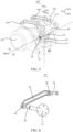
FIG. 3 is a schematic structural diagram of a waist structure according to an embodiment of the present disclosure. -
FIG. 4 is a sectional view of a waist structure according to an embodiment of the present disclosure. -
FIG. 5 is another axis view of a waist structure according to an embodiment of the present disclosure. -
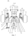
FIG. 6 is a front view of a drive assembly according to an embodiment of the present disclosure. -
FIG. 7 is an exploded diagram of a waist structure according to an embodiment of the present disclosure. -
FIG. 8 is still another axis view of a waist structure according to an embodiment of the present disclosure. -
FIG. 9 is a schematic diagram of an action principle of gravity compensation of a waist structure according to an embodiment of the present disclosure. -
FIG. 10 is another schematic diagram of an action principle of gravity compensation of a waist structure according to an embodiment of the present disclosure. - The technical schemes in all embodiments of the present disclosure will be clearly and completely described below with reference to the drawings in the embodiments of the present disclosure, and it is obvious that the described embodiments are only a part of the embodiments of the present disclosure, but not all of them. All other embodiments obtained by a person skilled in the art based on the embodiments of the present disclosure without creative efforts shall fall within the protection scope of the present disclosure.
- In the description of the present disclosure, it should be understood that orientation or position relationships indicated by the terms such as "center", "longitudinal", "transverse", "length", "width", "thickness", "on", "under", "front", "rear", "left", "right", "vertical", "horizontal", "top", "bottom", "inside", "outside", "clockwise", "anticlockwise", and the like are based on orientation or position relationships shown in the accompanying drawings, and are used only for ease and brevity of illustration and description, rather than indicating or implying that the mentioned apparatus or component must have a particular orientation or must be constructed and operated in a particular orientation. Therefore, such terms should not be construed as limiting of the present disclosure. In addition, the terms "first" and "second" are only for the purpose of description, and may not be understood as indicating or implying the relative importance or implicitly indicating the number of technical features indicated. Thus, features defined by "first" and "second" may expressly or implicitly include one or more of that feature. In the description of the present invention, "plurality" means two or more, unless otherwise expressly and specifically defined.
- In the description of the present disclosure, it should be noted that unless otherwise explicitly specified or defined, the terms such as "mount", "connect", and "couple" should be understood in a broad sense. For example, the connection may be a fixed connection, a detachable connection, an integral connection, a mechanical connection, an electrical connection, or mutual communication. Or, the connection may be a direct connection, an indirect connection through an intermediate medium, internal communication between two components, or an interaction relationship between two components. A person of ordinary skill in the art may understand the specific meanings of the foregoing terms in the present disclosure according to specific situations.
- In the present disclosure, unless otherwise explicitly stipulated and restricted, that a first feature is "on" or "below" a second feature may include that the first and second features are in direct contact, or may include that the first and second features are not in direct contact but in contact by using other features therebetween. In addition, that the first feature is "on", "above", or "over" the second feature includes that the first feature is right above and on the inclined top of the second feature or merely indicates that a level of the first feature is higher than that of the second feature. That the first feature is "below", "under", or "beneath" the second feature includes that the first feature is right below and at the inclined bottom of the second feature or merely indicates that a level of the first feature is lower than that of the second feature.
- In all embodiments of the present disclosure including the embodiments of both the claims and the specification (hereinafter referred to as "all embodiments of the present disclosure"). Many different implementations or examples are provided in the following disclosure to implement different structures of the present disclosure. To simplify the disclosure of the present disclosure, components and settings in particular examples are described below. Of course, they are merely examples and are not intended to limit the present disclosure. In addition, in the present disclosure, reference numerals and/or reference letters may be repeated in different examples. The repetition is for the purposes of simplification and clearness, and is not intended to indicate relationships between the various implementations and/or settings discussed herein. Moreover, the present disclosure provides examples of various particular processes and materials, but a person of ordinary skill in the art may be aware of application of other processes and/or use of other materials.
- All the embodiments of the present disclosure can be applied to various application scenarios such as artificial intelligence, a robot technology, mechanical and electrical integration, and the like.
- First, some nouns or terms appearing in a process of describing the embodiments of the present disclosure are suitable for the following explanations:
- Artificial Intelligence (AI) involves a theory, a method, a technology, and an application system that use a digital computer or a machine controlled by the digital computer to simulate, extend, and expand human intelligence, sense an environment, obtain knowledge, and use the knowledge to obtain an optimal result. In other words, AI is a comprehensive technology in computer science and attempts to understand the essence of intelligence and produce a new intelligent machine that can react in a manner similar to human intelligence. AI is to study the design principles and implementation methods of various intelligent machines, to enable the machines to have the functions of perception, reasoning, and decision-making.
- A robot can be a machine that can perform tasks such as work or movement through programming and automatic control. Robots have basic features such as perception, decision-making, and execution, which can assist or even replace human in completing dangerous, burdensome, and complex work, to improve the working efficiency and quality, serve human life, and expand or extend the range of human activities and abilities.
- The mechanical and electrical integration technology is a comprehensive high-tech that combines a microelectronic technology, a computer technology, an information technology, and a mechanical technology. It is an organic combination of the mechanical technology and the microelectronic technology.
- A degree of freedom refers to the number of independent motion parameters that needs to be given for determining a motion of a mechanism according to a mechanical principle. In a definition of a degree of freedom, uniqueness, necessity, and independence are three key words. Unique determination means that after these variables are given, the robot has a unique configuration. Necessity is a minimal concept, which means a minimum number of variables that can determine a status of the robot. Independence means that these variables can change independently.
- Specifically, referring to
FIG. 1 to FIG. 10 , the embodiments of the present disclosure provide awaist structure 100 of arobot 1000. Thewaist structure 100 includes a fixedplatform 10, a load-carryingbearing 20, aconnector 30, amovable platform 40, two ormore motors 50, and twodrive assemblies 60. The load-carryingbearing 20 can be arranged on the fixedplatform 10. Theconnector 30 includes afirst end 31 and asecond end 32 facing away from each other. Thefirst end 31 can be provided with ayaw shaft 33. Theyaw shaft 33 can be connected to aninner ring 21 of the load-carryingbearing 20. Thesecond end 32 can be provided with apitch shaft 34. Themovable platform 40 and thepitch shaft 34 can be rotatably connected. The two ormore motors 50 are arranged on the fixedplatform 10. Eachdrive assembly 60 corresponds to onemotor 50, and thedrive assemblies 60 are connected to themovable platform 40 and the correspondingmotors 50. The two ormore motors 50 can actuate thedrive assemblies 60 to drive themovable platform 40 to rotate relative to theconnector 30 in an axial direction of thepitch shaft 34, and can actuate thecorresponding drive assemblies 60 to drive themovable platform 40 and theconnector 30 to rotate relative to the fixedplatform 10 in an axial direction of theyaw shaft 33. - The "fixed
platform 10" and the "movable platform 40" can be meant to indicate that the two platforms can move relatively, rather than limiting that the fixedplatform 10 needs to be in a stationary state and that themovable platform 40 needs to be in a moving state. Therefore, the fixedplatform 10 and themovable platform 40 here may be referred to as a "first platform" and a "second platform", respectively. - Referring to
FIG. 1 , in an inertial coordinate system (inertial system) corresponding to thewaist structure 100, themovable platform 40 rotates relative to theconnector 30 in the axial direction of thepitch shaft 34. Equivalently, themovable platform 40 rotates relative to the fixedplatform 10 in a pitch angle direction (P1/P2 direction) of a posture angle. Themovable platform 40 rotates relative to the fixedplatform 10 in the axial direction of theyaw shaft 33. Equivalently, themovable platform 40 rotates relative to the fixedplatform 10 in a yaw angle direction (Y1/Y2 direction) of the posture angle. In this way, thewaist structure 100 has two degrees of freedom, and can achieve large-range and high-dexterity motions in the pitch angle (P1/P2) direction and the yaw angle (Y1/Y2) direction. - Referring to
FIG. 2, FIG. 2 is ahumanoid robot 1000 using awaist structure 100. Thehumanoid robot 1000 includes anupper limb structure 200, a body structure 300, awaist structure 100, and alower limb structure 400. A fixedplatform 10 of thewaist structure 100 is connected to thelower limb structure 400, and amovable platform 40 can be connected to the body structure 300. Thewaist structure 100 can connect the body structure 300 with thelower limb structure 400. When themovable platform 40 rotates relative to aconnector 30 in an axial direction of apitch shaft 34, themovable platform 40 rotates relative to the fixedplatform 10 in a pitch direction (P1/P2 direction), so that themovable platform 40 can drive the body structure 300 to perform actions of "bending down", "bending backward", and the like relative to thelower limb structure 400. When themovable platform 40 and theconnector 30 rotate relative to the fixedplatform 10 in an axial direction of ayaw shaft 33, themovable platform 40 rotates relative to the fixedplatform 10 in a yaw direction (Y1/ Y2 direction), so that themovable platform 40 can drive the body structure 300 to perform actions of "twisting the waist", "side swaying", and the like relative to thelower limb structure 400. In this way, thewaist structure 100 can achieve that the body structure 300 of the humanoid robot has two degrees of freedom in motion relative to thelower limb structure 400, and meet a demand of thehumanoid robot 1000 for large-range and high-dexterity motions, so that thehumanoid robot 1000 can make more postures. - The
waist structure 100 of this embodiment of the present disclosure is not limited to being applied to thehumanoid robot 1000. Some bio-robots, for example, a quadruped robot, a hexapod robot, an eight-legged robot, and a snake-type robot, which have the body structure 300 and thelower limb structure 400 can also use thewaist structure 100, so that the body structure 300 has two degrees of freedom in motion relative to thelower limb structure 400, to improve the motion range and motion dexterity of thebio-robot 1000. - Referring to
FIG. 1 , two ormore motors 50 serving as power output apparatuses can be arranged in thewaist structure 100, and eachmotor 50 corresponds to onedrive assembly 60. Thedrive assemblies 60 transmit power output by themotors 50 to themovable platform 40, to drive themovable platform 40 to rotate relative to the fixedplatform 10. Eachmotor 50 independently actuates thecorresponding drive assembly 60 to move, that is, motions of the twodrive assemblies 60 of thewaist structure 100 can be independent of each other. Thedrive assemblies 60 can be connected to themovable platform 40 and themotors 50 arranged in the fixedplatform 10. Equivalently, thedrive assemblies 60 can be connected to themovable platform 40 and the fixedplatform 10. In this way, the fixedplatform 10 and themovable platform 40 of thewaist structure 100 can be connected through the twodrive assemblies 60 that move independently. Furthermore, thewaist structure 100 has two degrees of freedom, so that thewaist structure 100 is in a parallel form. Compared with a serial form, in theparallel waist structure 100 of this embodiment of the present disclosure, themotor 50 has a relatively small rotational inertia and high rotation accuracy, so that a requirement for a torque of themotor 50 is relatively low. It is not necessary to arrange a reducer to ensure the drive accuracy, so that the number of essential parts of thewaist structure 100 can be reduced, thewaist structure 100 is more compact, and the weight of thewaist structure 100 is reduced. Furthermore, the rigidity of the parallel form can be greater than that of the serial form, so that thewaist structure 100 has relatively high carrying capacity. - In all embodiments of the present disclosure, referring to
FIG. 3, FIG. 3 is a simplified schematic diagram of the fixedplatform 10, themovable platform 40, theconnector 30, themotors 50, and thedrive assemblies 60 of thewaist structure 100. In the perspective ofFIG. 3 , themotors 50 can rotate clockwise, to actuate thedrive assemblies 60 to drive themovable platform 40 to rotate relative to the fixedplatform 10 clockwise (in the P1 direction), performing an action of "bending down". Similarly, themotors 50 can rotate anticlockwise (in the P2 direction), to actuate thedrive assemblies 60 to drive themovable platform 40 to rotate relative to the fixedplatform 10 anticlockwise, performing an action of "bending backward". - In all embodiments of the present disclosure, with reference to
FIG. 1 , a rotation direction of a revolute pair formed by thedrive assemblies 60 and the correspondingmotors 50 can be in the pitch angle (P1/P2) direction, so that the rotation, in the pitch angle direction, of themovable platform 40 driven by thedrive assemblies 60 has a relatively large rotation range, which can achieve that themovable platform 40 rotates relative to the fixedplatform 10 in a large angle in the pitch angle (P1/P2) direction, that is, themovable platform 40 can perform large-angle actions of "bending down" and "bending backward". - In all embodiments of the present disclosure, referring to
FIG. 1 andFIG. 3 , in thewaist structure 100 provided in this embodiment of the present disclosure, thedrive assemblies 60 can be connected to the correspondingmotors 50 in a manner of the revolute pair, and thedrive assemblies 60 can be connected to the movable platform at a position in front of or behind the movable platform. In this way, the drive assemblies do not need to be arranged between themovable platform 40 and the fixedplatform 10, so that themovable platform 40 and the fixedplatform 10 can be arranged more compactly, which is conductive to achieving a small-sized design of thewaist structure 100. - In summary, in the
waist structure 100 of this embodiment of the present disclosure, themotors 50 can actuate thedrive assemblies 60 to do a circumferential motion, to drive themovable platform 40 to do a large-range and high-dexterity motion relative to the fixedplatform 10 in the pitch angle (P1/P2) direction and the yaw angle (Y1/Y2) direction, so that thewaist structure 100 can be constituted into the parallel form, has the two degrees of freedom, and has the advantages of high carrying capacity, high dynamic response capacity, high motion accuracy, large motion range, compact structure, and the like. - The following describes the
waist structure 100 according to the embodiments of the present disclosure with reference to the accompanying drawings. - Referring to
FIG. 1 andFIG. 4 , the load-carryingbearing 20 can be arranged on the fixedplatform 10. Specifically, an outer ring 22 of the load-carryingbearing 20 can be connected to the fixedplatform 10, and theinner ring 21 of the load-carryingbearing 20 can rotate relative to the outer ring 22, that is, can rotate relative to the fixedplatform 10. Theyaw shaft 33 of thefirst end 31 of theconnector 30 can be connected to theinner ring 21 of the load-carryingbearing 20. Thepitch shaft 34 of thesecond end 32 of theconnector 30 can be rotatably connected to themovable platform 40, to connect themovable platform 40 to the fixedplatform 10. When themovable platform 40 is actuated to rotate in the yaw angle (Y1/Y2) direction, theconnector 30 and theinner ring 21 of the load-carryingbearing 20 rotate in the yaw angle (Y1/Y2) direction together, that is, themovable platform 40, theconnector 30, and theinner ring 21 of the load-carryingbearing 20 rotate relative to the fixedplatform 10 in the axial direction of the yaw shaft. When themovable platform 40 is actuated to rotate in the pitch angle (P1/P2) direction, themovable platform 40 rotates relative to theconnector 30 in the axial direction of thepitch shaft 34, to achieve that themovable platform 40 rotates relative to theconnector 30 in the axial direction of thepitch shaft 34. - In all embodiments of the present disclosure, with reference to
FIG. 5 , the two ormore motors 50 respectively independently actuate thecorresponding drive assemblies 60 to move. When the two ormore motors 50 synchronously rotate in the same direction, the two ormore motors 50 can actuate thecorresponding drive assemblies 60 to drive themovable platform 40 to rotate relative to theconnector 30 in the axial direction of thepitch shaft 34. When rotation directions of the two ormore motors 50 are different, the two ormore motors 50 can actuate thecorresponding drive assemblies 60 to drive themovable platform 40 and theconnector 30 to rotate relative to the fixedplatform 10 in the axial direction of theyaw shaft 33. - For example, referring to
FIG. 4 andFIG. 5 , taking two motors as an example, it is assumed that the twomotors 50 are separately amotor 501 and amotor 502, and that the twodrive assemblies 60 are separately adrive assembly 601 and adrive assembly 602. It is assumed that a clockwise direction R1 shown inFIG. 5 is a forward rotation direction of themotor 501 and themotor 502, and an anticlockwise direction R2 is a backward rotation direction of themotor 501 and themotor 502. - In all embodiments of the present disclosure, referring to
FIG. 4 andFIG. 5 , positions of the twodrive assemblies 60 connected to themovable platform 40 are located above a center-of-gravity position G of themovable platform 40. Referring toFIG. 6 , when themotor 501 and themotor 502 synchronously rotate at the same speed in the forward direction, thedrive assembly 601 and thedrive assembly 602 synchronously push themovable platform 40 to rotate in the pitch angle (P1/P2) P1 direction to perform an action of "bending down". Referring toFIG. 5 , when themotor 501 and themotor 502 synchronously rotate at the same speed in the backward direction, thedrive assembly 601 and thedrive assembly 602 synchronously pull themovable platform 40 to rotate in the pitch angle (P1/P2) P2 direction to perform an action of "bending backward". Referring toFIG. 6 , when speeds of themotor 501 and themotor 502 are the same, that themotor 501 rotates in the forward direction, and that themotor 502 rotates in the backward direction, thedrive assembly 601 pushes themovable platform 40, and thedrive assembly 602 pulls themovable platform 40, so that themovable platform 40 rotates in the yaw angle (Y1/Y2) Y1 direction. When speeds of themotor 501 and themotor 502 are the same, that themotor 501 rotates in the backward direction, and that themotor 502 rotates in the forward direction, thedrive assembly 601 pulls themovable platform 40, and thedrive assembly 602 pushes themovable platform 40, so that themovable platform 40 rotates in the yaw angle (Y1/Y2) Y2 direction. - In all embodiments of the present disclosure, referring to
FIG. 4 andFIG. 5 , when rotation directions of the twomotors 50 are different and speeds of the twomotors 50 are different, the twomotors 50 can actuate thecorresponding drive assemblies 60 to drive themovable platform 40 to rotate relative to theconnector 30 in the axial direction of thepitch shaft 34, and the twomotors 50 can actuate thecorresponding drive assemblies 60 to drive themovable platform 40 and theconnector 30 to rotate relative to the fixedplatform 10 in the axial direction of theyaw shaft 33. Positions of the twodrive assemblies 60 connected to themovable platform 40 can be respectively located on left and right sides of a center axis C1 of themovable platform 40. When speeds of themotor 501 and themotor 502 are different, thedrive assembly 601 and thedrive assembly 602 can drive themovable platform 40 to rotate in the pitch angle (P1/P2) direction and the yaw angle (Y1/Y2) direction. For example, referring toFIG. 5 , when themotor 501 rotates in the forward direction and that themotor 502 does not rotate, the drive assembly 601can push themovable platform 40 to rotate in the pitch angle (P1/P2) P1 direction. In addition, since only thedrive assembly 601 pushes themovable platform 40, the left side of the center axis of themovable platform 40 can be stressed, which can drive themovable platform 40 to rotate in the yaw angle (Y1/Y2) Y1 direction. - In all embodiments of the present disclosure, referring to
FIG. 4 andFIG. 5 , when rotation directions of the twomotors 50 are different and speeds of the twomotors 50 are different, the twomotors 50 can actuate thecorresponding drive assemblies 60 to drive themovable platform 40 to rotate relative to theconnector 30 in the axial direction of thepitch shaft 34, and the twomotors 50 can actuate thecorresponding drive assemblies 60 to drive themovable platform 40 and theconnector 30 to rotate relative to the fixedplatform 10 in the axial direction of theyaw shaft 33. For example, when rotation directions ofmotor 501 and themotor 502 are the same and that speeds of themotor 501 and themotor 502 are different, themotor 501 and themotor 502 can separately actuate thedrive assembly 601 and thedrive assembly 602 to supply different power to the left and right sides of the center axis of the of themovable platform 40, so that themovable platform 40 rotates in the yaw angle (Y1/Y2) direction while rotating in the pitch angle (P1/P2) direction. - Referring to
FIG. 4 andFIG. 5 , when rotation directions of themotor 501 and themotor 502 are different, if speeds of themotor 501 and themotor 502 are the same, a push force and a pull force which are supplied by thedrive assembly 601 and thedrive assembly 602 to the left and right sides of the center axis of themovable platform 40 can be in a balance, so that themovable platform 40 rotates in the yaw angle (Y1/Y2) direction. - In all embodiments of the present disclosure, referring to
FIG. 4 andFIG. 5 , when rotation directions of the twomotors 50 are different and speeds of the twomotors 50 are different, the twomotors 50 can actuate thecorresponding drive assemblies 60 to drive themovable platform 40 to rotate relative to theconnector 30 in the axial direction of thepitch shaft 34, and the twomotors 50 can actuate thecorresponding drive assemblies 60 to drive themovable platform 40 and theconnector 30 to rotate relative to the fixedplatform 10 in the axial direction of theyaw shaft 33. For example, when rotation directions ofmotor 501 and themotor 502 are different and that speeds of themotor 501 and themotor 502 are also different, a push force and a pull force which are supplied by thedrive assembly 601 and thedrive assembly 602 to the left and right sides of the center axis of themovable platform 40 can be not in a balance, so that themovable platform 40 rotates in the pitch angle (P1/P2) direction while rotating in the yaw angle (Y1/Y2) direction. - In this way, the rotations of the
movable platform 40 relative to the fixedplatform 10 in the two degrees of freedom, namely, the pitch angle (P1/P2) and the yaw angle (Y1/Y2), can be accurately controlled by controlling the rotation directions and speeds of themotor 501 and themotor 502, so that thewaist structure 100 can change various actions. - In all embodiments of the present disclosure, referring to
FIG. 6 andFIG. 7 , eachdrive assembly 60 includes: a movingpart 61, a first connectingrod 62, a second connectingrod 63, and a third connectingrod 64. With reference toFIG. 1 andFIG. 4 , themotors 50 can be connected to the movingparts 61, and can actuate the movingparts 61 to rotate circumferentially. Specifically, output shafts (not shown) of themotors 50 can be fixedly connected to the movingparts 61, to drive the movingparts 61 to rotate when the output shafts of the motors rotate. The first connectingrods 62 can be connected to the movingparts 61. The secondconnecting rods 63 can be connected to themovable platform 40. The thirdconnecting rods 64 can be connected and arranged between the first connectingrod 62 and the second connectingrod 63, and can be connected to the first connectingrod 62 and the second connectingrod 63. Referring toFIG. 6 , in this way, thedrive assembly 60 can change a direction of an actuating force supplied by themotor 50, and provide a push force or a pull force to themovable platform 40 in an axial direction of a roll shaft, so that the gravity of themovable platform 40 and the weight of a load on themovable platform 40 which need to be borne are small; and a relatively good dynamic response performance and carrying capacity are achieved. - In all embodiments of the present disclosure, referring to
FIG. 6 , eachdrive assembly 60 further includes a first knuckle bearing 65 and a second knuckle bearing 66. The first connectingrod 62 and the third connectingrod 64 can be connected through the first knuckle bearing 65 to form a first spherical pair, so that the third connectingrod 64 has a relatively large motion range relative to the first connectingrod 62. The second connectingrod 63 and the third connectingrod 64 can be connected through the second knuckle bearing 66 to form a second spherical pair, so that the second connectingrod 63 has a relatively large motion range relative to the third connectingrod 64. - Referring to
FIG. 5 and FIG. 6 , themotors 50 are fixedly connected to the fixedplatform 10. The movingparts 61 can rotate relative to the fixedplatform 10. Equivalently, the movingparts 61 can be revolute pairs connected to the fixedplatform 10. If "S" represents a spherical pair, and "R" represents a revolute pair, themovable platform 40 and the fixedplatform 10 can be connected through one revolute pair and two spherical pairs, to form an "RSS" type structure. Thedrive assembly 60 that connects themovable platform 40 to the fixedplatform 10 can be an "RSS" branched chain. The twodrive assemblies 60 can be in a parallel relationship, so that thewaist structure 100 is constituted into an "RSS" type parallel mechanism. With reference toFIG. 4 to FIG. 6 , the first spherical pair and the second spherical pair can provide a relatively large motion range, to support themovable platform 40 to rotate relative to the fixedplatform 10 in various postures in the two degrees of freedom, namely, the pitch angle (P1/P2) and the yaw angle (Y1/Y2), so that thewaist structure 100 has a relatively large working space. - In all embodiments of the present disclosure, referring to
FIG. 1 andFIG. 7 , themovable platform 40 includes asupport 41, two first connectingportions 42, and two second connectingportions 43. The two first connectingportions 42 can be symmetric about a center axis of thesupport 41, and thepitch shaft 34 can be connected to the two first connectingportions 42. The two second connectingportions 43 can be symmetric about the center axis of thesupport 41, and the two second connectingportions 43 can be respectively connected to the second connectingrods 63 of the twodrive assemblies 60. In this way, force bearing point of themovable platform 40 can be symmetric, so that it is easy to calculate an actuating force required to be inputted by eachmotor 50 when thedrive assembly 60 drives themovable platform 40 to move, to accurately control themovable platform 40 to move relative to the fixedplatform 10. - In all embodiments of the present disclosure, referring to
FIG. 1 , the two second connectingportions 43 can be provided with connectingslots 431. The secondconnecting rods 63 extend into the connectingslots 431 and can be connected to the second connectingportions 43. In this way, the second connectingrods 63 and the second connectingportions 43 can be combined reliably, and can be difficulty separated. - In all embodiments of the present disclosure, referring to
FIG. 1 , the two first connectingportions 42 extend from thesupport 41. The first connectingportions 42 can be provided with first throughholes 421. Thepitch shaft 34 can be connected to the first connectingportions 42 through the first throughholes 421. Specifically, the two first connectingportions 42 can be extending walls extending from thesupport 41. A mounting space can be formed between the two first connectingportions 42 and thesupport 41 and can be used for accommodating theconnector 30. Thepitch shaft 34 of theconnector 30 penetrates through the two first throughholes 421 to cause themovable platform 40 to be connected to theconnector 30 and to rotate around thepitch shaft 34. - In all embodiments of the present disclosure, referring to
FIG. 1 andFIG. 7 , in one embodiment, theconnector 30 further includes a connectingbody 35. There are twopitch shafts 34. The twopitch shafts 34 respectively extend from a first side and a second side of the connectingbody 35. The twopitch shafts 34 can be integrated with the body. The manufacturing process is simple. The twopitch shafts 34 extending from thefirst side 351 and thesecond side 352 of the connectingbody 35 respectively penetrate through the two first throughholes 421 to be respectively connected to the two first connectingportions 42. In another embodiment, there is onepitch shaft 34. Thepitch shaft 34 penetrates through the first side and the second side of the body and penetrates through the two first throughholes 421 respectively. In this way,different pitch shafts 34 can be removed from the connectingbody 35 for replacement. - In all embodiments of the present disclosure, referring to
FIG. 7 , the connectingbody 35 includes athird side 353 located between thefirst side 351 and thesecond side 352. Theyaw shaft 33 extends from the third side. In this way, theconnector 30 can be formed into a "T"-shaped structure. With reference toFIG. 1 , the axial direction of theyaw shaft 33 can be consistent with a yaw axis direction, and the axial direction of thepitch shaft 34 can be consistent with a pitch axis direction. By a simple structure, thewaist structure 100 has the two degrees of freedom in the pitch angle (P1/P2) direction and the yaw angle (Y1/Y2) direction, so that the manufacturing process can be simplified. - In all embodiments of the present disclosure, referring to
FIG. 7 , limitingportions 36 can be arranged at ends of thepitch shafts 34 away from the connectingbody 35. Theconnector 30 further includes connectingbearings 37. The connectingbearings 37 can be arranged in the first throughholes 421 and sleeve thepitch shafts 34. The limitingportions 36 can be used for limiting axial displacements of the connectingbearings 37 along thepitch shafts 34. - In all embodiments of the present disclosure, referring to
FIG. 1 andFIG. 4 , the fixedplatform 10 includes abase 11, two mountingportions 12, and ashaft hole 13. The two mountingportions 12 can be symmetric about a center axis of thebase 11. Mounting holes (which are blocked in the figure, not shown) can be formed in the mountingportions 12, and themotors 50 can be mounted in the mounting holes. Theshaft hole 13 can be formed in a center of thebase 11, and the load-carryingbearing 20 can be arranged in theshaft hole 13. - Specifically, the mounting
portions 12 can be platy structures symmetric about the center axis of thebase 11. In one embodiment, the two mountingportions 12 can be fixedly mounted on two sides of thebase 11. In another embodiment, the two mountingportions 12 respectively extend from two sides of thebase 11. Thewaist structure 100 of this embodiment of the present disclosure can adopt any one of the above embodiments, and will not be limited here. - In all embodiments of the present disclosure, referring to
FIG. 1 andFIG. 4 , themotors 50 can be mounted in the mounting holes and can be connected to the movingparts 61. The mountingportions 12 can be located between themotors 50 and the movingparts 61. If a space encircled by the two mountingportions 12 and thebase 11 is an internal space of the fixedplatform 10, and spaces outside the two mountingportions 12 opposite to the internal space can be external spaces of the fixedplatform 10, the twomotors 50 can be mounted in the external spaces of the fixedplatform 10. The twodrive assemblies 60, themovable platform 40, theconnector 30, and the load-carryingbearing 20 can be all arranged in the internal space of the fixedplatform 10, so that the internal space of the fixedplatform 10 can be compact in structure, and it is convenient to connect themotors 50 to an external power supply device or a power line. - Referring to
FIG. 4 , in one embodiments of the present disclosure, the outer ring 22 of the load-carryingbearing 20 can be arranged in theshaft hole 13 and can be fixedly connected to theshaft hole 13. In another embodiment, the load-carryingbearing 20 can be arranged above theshaft hole 13. The outer ring 22 of the load-carryingbearing 20 can be fixedly connected to thebase 11. Theinner ring 21 of the load-carryingbearing 20 corresponds to theshaft hole 13. In this way, the load-carryingbearing 20 and the base 11 can favorably bear the gravity of themovable platform 40 and the weight of the load on themovable platform 40, so that the carrying capacity of thewaist structure 100 is improved. Thewaist structure 100 of this embodiment of the present disclosure can adopt any one of the above embodiments, and will not be limited here. - In all embodiments of the present disclosure, referring to
FIG. 5 , the twomotors 50 and the twodrive assemblies 60 can be symmetric about the center axis C2 of thebase 11. In some embodiments, the twomotors 50, the twodrive assemblies 60, and the two second connectingportions 43 of themovable platform 40 can be symmetric about the center axis C2 of thebase 11. In this way, the structure of thewaist structure 100 can be in a left and right symmetry arrangement, which can effectively ensure the symmetry of a motion space of the movable platform. - In all embodiments of the present disclosure, referring to
FIG. 4 ,FIG. 7 , andFIG. 8 , thewaist structure 100 further includes apull wire module 70, configured to compensate the gravity of themovable platform 40. Thepull wire module 70 includes afollower 71, apulley assembly 72, afixed part 73, anelastic part 74, and apull wire 75. Thefollower 71 can be connected to theinner ring 21 of the load-carryingbearing 20. Thepulley assembly 72 and thefixed part 73 can be arranged on thefollower 71. Theelastic part 74 can be connected to the fixedpart 73. Thepull wire 75 cooperates with thepulley assembly 72. One end of thepull wire 75 can be connected to theelastic part 74, and the other end of thepull wire 75 can be connected to themovable platform 40. In one embodiment, theelastic part 74 can be a tension spring, and thepull wire 75 can be a metal wire. - When the
movable platform 40 rotates relative to the fixedplatform 10 around thepitch shaft 34, theelastic part 74 can be stretched according to a degree of pitching of themovable platform 40, to provide an elastic force to compensate the gravity of themovable platform 40 and the weight of the load on themovable platform 40, that is, to provide gravity compensation to improve the carrying capacity of thewaist structure 100. A stress status of thewaist structure 100 during movement of therobot 1000 can be effectively improved, and the response speed can be increased. In addition, under the action of the gravity compensation of thepull wire module 70, thewaist structure 100 can be stably kept in a certain posture without deformation, to improve the motion accuracy. - When the
movable platform 40 rotates relative to the fixedplatform 10 in the axial direction of theyaw shaft 33, thefollower 71 follows themovable platform 40 to rotate relative to the fixedplatform 10 in the axial direction of theyaw shaft 33. In this way, a change in a force direction of a pull force of thepull wire 75 caused by the rotation of themovable platform 40 around theyaw shaft 33 can be avoided, and motion decoupling can be achieved, so that the change of the pull force of thepull wire 75 only depends on a change in an angle of themovable platform 40 around the pitch shaft 34 (an angle change along the pitch angle (P1/P2)). - In all embodiments of the present disclosure, with reference to
FIG. 7 ,FIG. 8 , andFIG. 9 , when theelastic part 74 can be in a stretched state, the gravity of themovable platform 40 can be compensated on the basis of a first distance, a second distance, an elongation of theelastic part 74, a pitch inclination angle, and a pull wire inclination angle. The first distance can be a distance between a center-of-gravity position of themovable platform 40 and an axis position of eachpitch shaft 34; the second distance can be a distance between a center of gravity of apulley 7211 of thepulley assembly 72 and an axis position of theyaw shaft 33; the pitch inclination angle can be an angle that themovable platform 40 rotates around thepitch shaft 34 relative to a center-of-gravity direction; and the pull wire inclination angle can be an inclination angle of a portion of thepull wire 75 located between thepulley 7211 and themovable platform 40 relative to a plane where the fixedplatform 10 can be located. -
FIG. 9 is a schematic diagram of an action principle of gravity compensation achieved by thepull wire module 70 in a state that themovable platform 40 rotates around thepitch shaft 34 relative to the fixedplatform 10. - Point A can be a connecting point between the
pull wire 75 and themovable platform 40; point B can be the center of gravity and rotation center of thepulley 7211 in the structure of thepulley 7211; point O can be the center-of-gravity position of thepitch shaft 34; point G can be the center-of-gravity position of themovable platform 40; and point C can be a vertical point of a vertical line between point A and line segment OG. Point O may also be a point located at the axis position of theyaw shaft 33. To facilitate the following description, in this embodiment shown inFIG. 9 , it is assumed that thepulley 7211 in thepulley assembly 72 has a relatively small radius. A distance between thepull wire 75 on thepulley 7211 and the rotation center of thepulley 7211 is relatively short, that is, a distance between thepull wire 75 on thepulley 7211 and point B is relatively short, so that a distance between point A and point B approximatively represents a length of thepull wire 75 between point A and point B. Or, it is assumed that thepull wire 75 passes through the rotation center B of thepulley 7211. In this way, a distance between point A and point B is a length of thepull wire 75 between point A and point B. - It is set that a length of line segment AC is la, that a distance between point C and point O is lb, that a distance between point B and point O is the second distance lc, that a distance between point G and point O can be the first distance lh, that a distance between point A and point O can be ls, that a rectangular plane coordinate system can be built by taking point O as an origin, that a yaw angle of line segment OG relative to a y axis direction of the coordinate system can be the pitch inclination angle θ, and that an included angle between line segment AB and an x axis of the coordinate system can be the pull wire inclination angle α. Thus, a rigidity k of the
elastic part 74 required for gravity compensation satisfies:

where Δ can be the elongation of theelastic part 74, that is, a stretched length of theelastic part 74; and mg can be an equivalent gravity of the center-of-gravity position G of themovable platform 40. In the state that themovable platform 40 rotates around thepitch shaft 34 relative to the fixedplatform 10, mg will not change. Therefore, the rigidity of theelastic part 74 can be related to the first distance lh, the second distance lc, the elongation Δ of theelastic part 74, the pitch inclination angle θ, and the pull wire inclination angle α. The gravity of themovable platform 40 can be compensated on the basis of the above parameters. - Specifically, point B and point O can be on the same horizontal line. It is assumed that a torque generated by the gravity mg at point O is T1, T1=mglhsinθ. It is assumed that the
elastic part 74 is stretched, so that a torque provided by thepull wire module 70 at point A is T2, T2=klcΔsinα. In case of T1=T2, the torque provided by thepull wire module 70 can compensate for the torque generated by the gravity mg, so that if the rigidity k of theelastic part 74 satisfies:
pull wire module 70 can realize a gravity compensation function. - Further, after the parts of the
waist structure 100 are confirmed, the positions of thepulley 7211 and theconnector 30 are fixed, so the second distance lc will not change. Referring toFIG. 9 ,


waist structure 100 can be confirmed, the center-of-gravity position G of themovable platform 40 can be confirmed; the position of connecting point A between thepull wire 75 and themovable platform 40 can be fixed; the center-of-gravity position O of thepitch shaft 34 can be fixed; and the position of point C can be also fixed. Therefore, the distance lh between point G and point O, the distance ls between point A and point O, the distance lb between point C and point O, and the distance la between point A and point C will not change. Therefore, a size of the rigidity k of theelastic part 74 required for gravity compensation only depends on the pitch inclination angle θ and the elongation △ of theelastic part 74. When the pitch inclination angle θ=90°, the elongation △ of theelastic part 74 can be the maximum, and the rigidity k of theelastic part 74 required for gravity compensation can be the maximum; and thepull wire module 70 can completely compensate for the gravity mg. In this way, the rigidity k of theelastic part 74 corresponding to the pitch inclination angle θ=90° is used as a rigidity baseline of theelastic part 74, to meet a gravity compensation requirement for themovable platform 40. - In all embodiments of the present disclosure, with reference with
FIG. 10 , when theelastic part 74 is in the stretched state, after the center-of-gravity position of themovable platform 40 skews, the gravity of the movable platform can be compensated on the basis of a third distance, the first distance, the second distance, the elongation of theelastic part 74, the pitch inclination angle, and the pull wire inclination angle; and the third distance can be a distance between the center-of-gravity position of the movable platform before skewing and the center-of-gravity position of the movable platform after skewing. After the center-of-gravity position of themovable platform 40 skews relative to the initial position, namely, point G, (the center-of-gravity position of themovable platform 40 before skewing) due to a motion or a change in the load, the center-of-gravity position of themovable platform 40 after skewing is set to be G', so that a distance between point G and G' can be △x (which is the third distance). In this case, the torque T1 generated by the gravity mg at point O is T1', T1'=mg(lhsinθ+△x), T1'>T1. In this case, themotor 50 provides a torque T3, T3=mgΔx, and thepull wire module 70 provides a torque T2, T2=klc△sinα=mglhsinθ. The gravity compensation can be achieved by combining the torque T2 and the torque T3, T2+T3=T1'. That is, in this case, the structure of thepull wire 75 can still provide part of the gravity compensation, to improve the stress status of thewaist structure 100 and improve the motion response speed and the motion accuracy. - In all embodiments of the present disclosure, referring to
FIG. 8 , a receivingspace 48 and apull wire hole 49 can be formed in themovable platform 40. Thepull wire 75 includes apull wire head 751. Thepull wire head 751 can be received in the receivingspace 48, and thepull wire 75 can be led out from thepull wire hole 49. In this way, the receivingspace 48 can play a role of protecting thepull wire head 751. - In all embodiments of the present disclosure, referring to
FIG. 4 andFIG. 8 , thefollower 71 includes a followingportion 711, a fixingportion 712, and an extendingportion 713. The followingportion 711 can be connected to theinner ring 21 of the load-carryingbearing 20. Specifically, theconnector 30 and the followingportion 711 can be respectively connected to two sides, facing away from each other, of theinner ring 21 of the load-carryingbearing 20. A fixinghole 7121 can be formed in the fixingportion 712, and thefixed part 73 can be mounted in thefixing hole 7121. Thepulley assembly 72 can be arranged at the extendingportion 713. - In all embodiments of the present disclosure, referring to
FIG. 4 , thefollower 71 includes two extendingportions 713 spaced from each other; apulley slot 7131 can be formed between the two extendingportions 713; and each extendingportion 713 can be provided with apin hole 7132. Thepulley assembly 72 includes twopulley systems 721, and the twopulley systems 721 can be arranged at the extendingportions 713 in a spaced manner. With reference toFIG. 9 , thepulley systems 721 includepulleys 7211, spacers (not shown), and pins 7212. Thepulleys 7211 can be arranged between the two extendingportions 713. Thepins 7212 penetrate through the pin holes 7132 and thepulleys 7211. The spacers can be arranged between thepulleys 7211 and the extendingportions 713. Referring toFIG. 9 , the center-of-gravity position of thepulley 7211 of thetopmost pulley system 721 of the twopulley systems 721 corresponds to point B inFIG. 9 , and the center-of-gravity position of thepulley 7211 and the center-of-gravity position of thepitch shaft 34 can be on the same horizontal line. - In some embodiments of the present disclosure may be formed by using any combination of all the foregoing technical solutions, and details are not described here.
- Referring to
FIG. 2 , the embodiments of the present disclosure provide arobot 1000. Therobot 1000 includes thewaist structure 100 according to any one of the above implementations, a body structure 300, and alower limb structure 400. The body structure 300 can be connected to themovable platform 40. Thelower limb structure 400 can be connected to the fixedplatform 10. By using thewaist structure 100 in the parallel "RSS" form to connect the body structure 300 to thelower limb structure 400, therobot 1000 provided by this embodiment of the present disclosure can achieve motions of anupper limb structure 200 relative to thelower limb structure 400 in two degrees of freedom, namely, in a pitch angle (P1/P2) direction and a yaw angle (Y1/Y2) direction, so that therobot 1000 has relatively high load-carrying capacity and relatively good drive capacity. - In the foregoing embodiments, description of each embodiment focuses on a different part, and for parts that are not described in detail in one embodiment, refer to the related description of other embodiments.
- In the descriptions of the embodiments of the present disclosure, specific features, structures, materials, or characteristics may be combined in a proper manner in any one or more of the embodiments or examples.
- The foregoing descriptions are merely specific implementations of the present disclosure, but are not intended to limit the protection scope of the present disclosure. Any variation or replacement readily figured out by a person skilled in the art within the technical scope disclosed in the present disclosure shall fall within the protection scope of the present disclosure. Therefore, the protection scope of the present disclosure shall be subject to the protection scope of the claims.
Claims (20)
- A waist structure of a robot, comprising:a fixed platform;a load-carrying bearing arranged on the fixed platform;a connector comprising a first end and a second end facing away from each other, the first end being provided with a yaw shaft, the yaw shaft being connected to an inner ring of the load-carrying bearing, and the second end being provided with a pitch shaft;a movable platform rotatably connected to the pitch shaft;two motors arranged on the fixed platform; andtwo drive assemblies, each drive assembly corresponding to one motor, and the drive assemblies being connected to the movable platform and the corresponding motors;wherein the motors are configured to actuate the drive assemblies to do a circumferential motion, to drive the movable platform to rotate relative to the connector in an axial direction of the pitch shaft, and actuating the corresponding drive assemblies to drive the movable platform and the connector to rotate relative to the fixed platform in an axial direction of the yaw shaft.
- The waist structure of the robot according to claim 1, wherein the two motors respectively and independently actuate the corresponding drive assemblies to move;when the two motors synchronously rotate in a same direction, the two motors are configured to actuate the corresponding drive assemblies to drive the movable platform to rotate relative to the connector in the axial direction of the pitch shaft; andwhen rotation directions of the two motors are different, the two motors are configured to actuate the corresponding drive assemblies to drive the movable platform and the connector to rotate relative to the fixed platform in the axial direction of the yaw shaft.
- The waist structure of the robot according to claim 2, wherein when speeds of the two motors are different, the two motors are configured to actuate the corresponding drive assemblies to drive the movable platform to rotate relative to the connector in the axial direction of the pitch shaft, and actuate the corresponding drive assemblies to drive the movable platform and the connector to rotate relative to the fixed platform in the axial direction of the yaw shaft.
- The waist structure of the robot according to claim 2 or 3, wherein when rotation directions of the two motors are the same and speeds of the two motors are different, the two motors are configured to actuate the corresponding drive assemblies to drive the movable platform to rotate relative to the connector in the axial direction of the pitch shaft, and the two motors actuate the corresponding drive assemblies to drive the movable platform and the connector to rotate relative to the fixed platform in the axial direction of the yaw shaft.
- The waist structure of the robot according to claim 2 or 3, wherein when rotation directions of the motors are different and speeds of the two motors are different, the two motors are configured to actuate the corresponding drive assemblies to drive the movable platform to rotate relative to the connector in the axial direction of the pitch shaft, and the two motors actuate the corresponding drive assemblies to drive the movable platform and the connector to rotate relative to the fixed platform in the axial direction of the yaw shaft.
- The waist structure of the robot according to any one of claims 1 to 5, wherein each drive assembly comprises:a moving part connected to the corresponding motor to form a revolute pair;a first connecting rod connected to the moving part;a second connecting rod connected to the movable platform; anda third connecting rod connected and arranged between the first connecting rod and the second connecting rod and is connected to the first connecting rod and the second connecting rod.
- The waist structure of the robot according to claim 6, wherein each drive assembly further comprises a first knuckle bearing and a second knuckle bearing; the first connecting rod and the third connecting rod are connected through the first knuckle bearing to form a first spherical pair; and the second connecting rod and the third connecting rod are connected through the second knuckle bearing to form a second spherical pair.
- The waist structure of the robot according to claim 6 or 7, wherein the movable platform comprises:a support;two first connecting portions being symmetric about a center axis of the support, the pitch shaft being connected to the two first connecting portions; andtwo second connecting portions being symmetric about the center axis of the support, wherein the two second connecting portions are respectively connected to the second connecting rods of the two drive assemblies.
- The waist structure of the robot according to claim 8, wherein the two first connecting portions extend from the support; the first connecting portions are provided with a first through hole; and the pitch shaft is connected to the first connecting portions through the first through hole.
- The waist structure of the robot according to claim 9, wherein the connector further comprises a connecting body; and there are two pitch shafts which extend respectively from a first side and a second side of the connecting body and respectively penetrate through two of the first through holes.
- The waist structure of the robot according to claim 10, wherein limiting portions are provided at ends of the pitch shafts away from the connecting body; the connector further comprises connecting bearings; the connecting bearings are provided in the first through holes and sleeve the pitch shafts; and the limiting portions are configured to limit axial displacements of the connecting bearings along the pitch shafts.
- The waist structure of the robot according to claim 8, wherein the two second connecting portions are provided with connecting slots; and the second connecting rods extend into the connecting slots and are connected to the second connecting portions.
- The waist structure of the robot according to any one of claims 1 to 12, wherein the fixed platform comprises:a base;two mounting portions, the two mounting portions being symmetric about a center axis of the base, mounting holes being formed in the mounting portions, and the motors being mounted in the mounting holes; anda shaft hole formed in a center of the base, the load-carrying bearing being arranged in the shaft hole.
- The waist structure of the robot according to any one of claims 1 to 13, wherein the waist structure further comprises a pull wire module, configured to compensate the gravity of the movable platform; and the pull wire module comprises:a follower connected to the inner ring of the load-carrying bearing;a pulley assembly arranged on the follower;a fixed part arranged on the follower;an elastic part fixedly connected to the fixed part; anda pull wire cooperating with the pulley assembly, one end of the pull wire being connected to the elastic part, and the other end of the pull wire being connected to the movable platform, whereinthe follower is configured to rotate around the yaw shaft relative to the fixed platform when the movable platform rotates around the yaw shaft relative to the fixed platform.
- The waist structure of the robot according to claim 14, wherein when the elastic part is in a stretched state, the gravity of the movable platform is compensated on the basis of a first distance, a second distance, an elongation of the elastic part, a pitch inclination angle, and a pull wire inclination angle; the first distance is a distance between a center-of-gravity position of the movable platform and an axis position of each pitch shaft; the second distance is a distance between a center of gravity of a pulley of the pulley assembly and an axis position of the yaw shaft; the pitch inclination angle is an angle that the movable platform rotates around the pitch shaft relative to a center-of-gravity direction; and the pull wire inclination angle is an inclination angle of a portion of the pull wire located between the pulley and the movable platform relative to a plane where the fixed platform is located.
- The waist structure of the robot according to claim 15, wherein when the elastic part is in the stretched state, after the center-of-gravity position of the movable platform shifts, the gravity of the movable platform is compensated on the basis of a third distance, the first distance, the second distance, the elongation of the elastic part, the pitch inclination angle, and the pull wire inclination angle; and the third distance is a distance between the center-of-gravity position of the movable platform before shifting and the center-of-gravity position of the movable platform after skewing.
- The waist structure of the robot according to claim 14, wherein a receiving space and a pull wire hole are formed in the movable platform; the pull wire comprises a pull wire head; the pull wire head is received in the receiving space; and the pull wire is led out from the pull wire hole.
- The waist structure of the robot according to claim 14, wherein the follower comprises:a following portion connected to the inner ring of the load-carrying bearing;a fixing portion provided with a fixing hole, the fixed part being mounted in the fixing hole; andan extending portion, the pulley assembly being arranged at the extending portion.
- The waist structure of the robot according to claim 17, wherein the follower comprises two extending portions spaced from each other; a pulley slot is formed between the two extending portions; each extending portion is provided with a pin hole; the pulley assembly comprises two pulley systems; the two pulley systems are arranged at the extending portions in a spaced manner; the pulley systems comprise pulleys, spacers, and pins; the pulleys are arranged between the two extending portions; the pins penetrate through the pin holes and the pulleys; and the spacers are arranged between the pulleys and the extending portions.
- A robot, comprising:the waist structure according to any one of claims 1 to 19;a body structure connected to the movable platform of the waist structure; anda lower limb structure connected to the fixed platform of the waist structure.
Applications Claiming Priority (2)
| Application Number | Priority Date | Filing Date | Title |
|---|---|---|---|
| CN202210003032.1A CN116423530A (en) | 2022-01-04 | 2022-01-04 | The waist structure of the robot and the robot |
| PCT/CN2022/125435 WO2023130793A1 (en) | 2022-01-04 | 2022-10-14 | Waist structure of robot and robot |
Publications (4)
| Publication Number | Publication Date |
|---|---|
| EP4393652A1 true EP4393652A1 (en) | 2024-07-03 |
| EP4393652A4 EP4393652A4 (en) | 2025-01-01 |
| EP4393652C0 EP4393652C0 (en) | 2026-01-21 |
| EP4393652B1 EP4393652B1 (en) | 2026-01-21 |
Family
ID=87073006
Family Applications (1)
| Application Number | Title | Priority Date | Filing Date |
|---|---|---|---|
| EP22918246.4A Active EP4393652B1 (en) | 2022-01-04 | 2022-10-14 | Waist structure of robot and robot |
Country Status (4)
| Country | Link |
|---|---|
| US (1) | US20230294308A1 (en) |
| EP (1) | EP4393652B1 (en) |
| CN (1) | CN116423530A (en) |
| WO (1) | WO2023130793A1 (en) |
Families Citing this family (8)
| Publication number | Priority date | Publication date | Assignee | Title |
|---|---|---|---|---|
| CN117775136B (en) * | 2023-12-25 | 2026-06-23 | 之江实验室 | Hydraulic wheel leg robot and hydraulic driving system thereof |
| WO2025235079A1 (en) * | 2024-05-09 | 2025-11-13 | Timeback Incorporated | Ball joint differential for robot |
| CN118682791B (en) * | 2024-08-29 | 2024-12-17 | 上海傅利叶智能科技有限公司 | Waist crotch subassembly and humanoid robot |
| CN119610206A (en) * | 2025-01-13 | 2025-03-14 | 哈尔滨工业大学 | A three-degree-of-freedom serial-parallel hybrid humanoid robot waist structure |
| CN120002709A (en) * | 2025-04-17 | 2025-05-16 | 深圳逐际动力科技有限公司 | Robot waist omnidirectional driven driven shaft assembly, robot waist omnidirectional driving assembly and robot |
| CN119974053B (en) * | 2025-04-17 | 2025-08-08 | 深圳逐际动力科技有限公司 | Waist omnidirectional driving component for humanoid robot and humanoid robot |
| CN120347814B (en) * | 2025-06-24 | 2025-10-28 | 广东天太机器人有限公司 | Robot and waist structure thereof |
| CN120588275A (en) * | 2025-07-25 | 2025-09-05 | 上海傅利叶智能科技有限公司 | Waist assembly and humanoid robot |
Family Cites Families (17)
| Publication number | Priority date | Publication date | Assignee | Title |
|---|---|---|---|---|
| CN101850554B (en) * | 2010-04-30 | 2012-04-11 | 东南大学 | Low-noise humanoid robot head system |
| US9360093B2 (en) * | 2011-08-16 | 2016-06-07 | Baylor University | Six-degree-of-freedom cam-controlled support platform |
| CN202964644U (en) * | 2012-11-20 | 2013-06-05 | 北京博纳启源科技有限公司 | Electric two-degree-of-freedom motion platform |
| CN103192377B (en) * | 2013-03-18 | 2015-11-04 | 安科智慧城市技术(中国)有限公司 | Freely-movable device |
| CN104390796B (en) * | 2014-10-09 | 2017-04-05 | 北京工业大学 | A kind of upper body experiment porch of anthropomorphic robot |
| CN104985585B (en) * | 2015-05-12 | 2017-06-16 | 北京理工大学 | A kind of bionical waist mechanism of the anthropomorphic robot of telescopic drive |
| US20210387346A1 (en) * | 2016-10-22 | 2021-12-16 | Carla R. Gillett | Humanoid robot for performing maneuvers like humans |
| CN106737593B (en) * | 2016-12-31 | 2019-06-04 | 中国工程物理研究院激光聚变研究中心 | Decoupling single-branch-driven three-degree-of-freedom device with adjustable dynamic characteristics |
| CN106985149A (en) * | 2017-06-06 | 2017-07-28 | 江苏金刚文化科技集团股份有限公司 | Robot of a kind of half body robot and remote control half body |
| CN107243921B (en) * | 2017-06-14 | 2020-04-14 | 东北大学 | A waist joint for humanoid robot |
| CN109397245A (en) * | 2018-12-11 | 2019-03-01 | 哈尔滨工业大学(深圳) | A kind of nursing robot |
| CN109893398A (en) * | 2019-04-04 | 2019-06-18 | 广东铭凯医疗机器人有限公司 | A kind of bionical healing robot |
| IT201900007848A1 (en) * | 2019-06-03 | 2020-12-03 | Milano Politecnico | Load compensation device, in particular gravitational loads, applicable to exoskeletons |
| CN210284427U (en) * | 2019-07-31 | 2020-04-10 | 青岛农业大学 | A hang self-adaptation adjusting part for robot |
| CN110774277A (en) * | 2019-12-02 | 2020-02-11 | 福州大学 | Snake-shaped arm three-degree-of-freedom wrist joint and movement method |
| CN111059431B (en) * | 2019-12-24 | 2022-11-15 | 燕山大学 | A two-degree-of-freedom parallel rotating platform with eccentric moment unloading device |
| US11440198B2 (en) * | 2020-04-28 | 2022-09-13 | Ubtech Robotics Corp Ltd | Control system and method for movement of neck mechanism for robot |
-
2022
- 2022-01-04 CN CN202210003032.1A patent/CN116423530A/en active Pending
- 2022-10-14 EP EP22918246.4A patent/EP4393652B1/en active Active
- 2022-10-14 WO PCT/CN2022/125435 patent/WO2023130793A1/en not_active Ceased
-
2023
- 2023-05-25 US US18/202,222 patent/US20230294308A1/en active Pending
Also Published As
| Publication number | Publication date |
|---|---|
| EP4393652C0 (en) | 2026-01-21 |
| CN116423530A (en) | 2023-07-14 |
| WO2023130793A1 (en) | 2023-07-13 |
| EP4393652B1 (en) | 2026-01-21 |
| US20230294308A1 (en) | 2023-09-21 |
| EP4393652A4 (en) | 2025-01-01 |
Similar Documents
| Publication | Publication Date | Title |
|---|---|---|
| EP4393652B1 (en) | Waist structure of robot and robot | |
| TWI603824B (en) | Rotating structure of robot | |
| US11945528B2 (en) | Hip joint mechanism and humanoid robot | |
| US11897122B2 (en) | Robot hand | |
| KR20050099503A (en) | Speed reducer for industrial robot | |
| CN224043820U (en) | Joint module and finger | |
| JP2018089766A (en) | Industrial robot | |
| CN116423473A (en) | The waist structure of the robot and the robot | |
| US20180290295A1 (en) | Rotational driving mechanism in a robot | |
| CN119974053B (en) | Waist omnidirectional driving component for humanoid robot and humanoid robot | |
| CN118182675A (en) | Humanoid robot and its lower limb device | |
| CN118682791A (en) | Waist and hip assembly and humanoid robot | |
| CN106163746A (en) | The articulation mechanism of humanoid robot | |
| KR20110124925A (en) | Joint module for robot and joint system for robot with same | |
| CN120862748B (en) | Central driving type three-degree-of-freedom humanoid robot shoulder joint mechanism | |
| JP2005246565A (en) | Leg part mechanism of robot device | |
| CN120606919A (en) | Unilateral parallel link ankle structure and robot | |
| JP4675356B2 (en) | Legged mobile robot | |
| HK40088367A (en) | Waist structure of robot and robot | |
| KR102331630B1 (en) | Robot Joint | |
| KR100774887B1 (en) | Triaxial joint device of manipulator | |
| HK40088366A (en) | Waist structure of robot and robot | |
| JP2005161436A (en) | Waist yaw axis drive device for humanoid robot | |
| CN119910692B (en) | Three-degree-of-freedom decoupling wrist | |
| CN121468652B (en) | A multimodal robot elbow joint mechanism |
Legal Events
| Date | Code | Title | Description |
|---|---|---|---|
| STAA | Information on the status of an ep patent application or granted ep patent |
Free format text: STATUS: THE INTERNATIONAL PUBLICATION HAS BEEN MADE |
|
| PUAI | Public reference made under article 153(3) epc to a published international application that has entered the european phase |
Free format text: ORIGINAL CODE: 0009012 |
|
| STAA | Information on the status of an ep patent application or granted ep patent |
Free format text: STATUS: REQUEST FOR EXAMINATION WAS MADE |
|
| 17P | Request for examination filed |
Effective date: 20240328 |
|
| AK | Designated contracting states |
Kind code of ref document: A1 Designated state(s): AL AT BE BG CH CY CZ DE DK EE ES FI FR GB GR HR HU IE IS IT LI LT LU LV MC ME MK MT NL NO PL PT RO RS SE SI SK SM TR |
|
| A4 | Supplementary search report drawn up and despatched |
Effective date: 20241204 |
|
| RIC1 | Information provided on ipc code assigned before grant |
Ipc: B62D 57/028 20060101ALI20241128BHEP Ipc: B62D 57/032 20060101ALI20241128BHEP Ipc: B25J 17/00 20060101ALI20241128BHEP Ipc: B25J 19/00 20060101ALI20241128BHEP Ipc: B25J 11/00 20060101ALI20241128BHEP Ipc: B25J 9/08 20060101ALI20241128BHEP Ipc: B25J 9/00 20060101AFI20241128BHEP |
|
| DAV | Request for validation of the european patent (deleted) | ||
| DAX | Request for extension of the european patent (deleted) | ||
| GRAP | Despatch of communication of intention to grant a patent |
Free format text: ORIGINAL CODE: EPIDOSNIGR1 |
|
| STAA | Information on the status of an ep patent application or granted ep patent |
Free format text: STATUS: GRANT OF PATENT IS INTENDED |
|
| INTG | Intention to grant announced |
Effective date: 20250811 |
|
| GRAS | Grant fee paid |
Free format text: ORIGINAL CODE: EPIDOSNIGR3 |
|
| GRAA | (expected) grant |
Free format text: ORIGINAL CODE: 0009210 |
|
| STAA | Information on the status of an ep patent application or granted ep patent |
Free format text: STATUS: THE PATENT HAS BEEN GRANTED |
|
| AK | Designated contracting states |
Kind code of ref document: B1 Designated state(s): AL AT BE BG CH CY CZ DE DK EE ES FI FR GB GR HR HU IE IS IT LI LT LU LV MC ME MK MT NL NO PL PT RO RS SE SI SK SM TR |
|
| REG | Reference to a national code |
Ref country code: CH Ref legal event code: F10 Free format text: ST27 STATUS EVENT CODE: U-0-0-F10-F00 (AS PROVIDED BY THE NATIONAL OFFICE) Effective date: 20260121 |
|
| REG | Reference to a national code |
Ref country code: DE Ref legal event code: R096 Ref document number: 602022029022 Country of ref document: DE |
|
| REG | Reference to a national code |
Ref country code: IE Ref legal event code: FG4D |
|
| U01 | Request for unitary effect filed |
Effective date: 20260203 |
|
| U07 | Unitary effect registered |
Designated state(s): AT BE BG DE DK EE FI FR IT LT LU LV MT NL PT RO SE SI Effective date: 20260206 |
|
| PG25 | Lapsed in a contracting state [announced via postgrant information from national office to epo] |
Ref country code: RS Free format text: LAPSE BECAUSE OF FAILURE TO SUBMIT A TRANSLATION OF THE DESCRIPTION OR TO PAY THE FEE WITHIN THE PRESCRIBED TIME-LIMIT Effective date: 20260421 |
|
| PG25 | Lapsed in a contracting state [announced via postgrant information from national office to epo] |
Ref country code: ES Free format text: LAPSE BECAUSE OF FAILURE TO SUBMIT A TRANSLATION OF THE DESCRIPTION OR TO PAY THE FEE WITHIN THE PRESCRIBED TIME-LIMIT Effective date: 20260121 |
|
| PG25 | Lapsed in a contracting state [announced via postgrant information from national office to epo] |
Ref country code: PL Free format text: LAPSE BECAUSE OF FAILURE TO SUBMIT A TRANSLATION OF THE DESCRIPTION OR TO PAY THE FEE WITHIN THE PRESCRIBED TIME-LIMIT Effective date: 20260121 |
|
| PG25 | Lapsed in a contracting state [announced via postgrant information from national office to epo] |
Ref country code: GR Free format text: LAPSE BECAUSE OF FAILURE TO SUBMIT A TRANSLATION OF THE DESCRIPTION OR TO PAY THE FEE WITHIN THE PRESCRIBED TIME-LIMIT Effective date: 20260422 |
|
| PG25 | Lapsed in a contracting state [announced via postgrant information from national office to epo] |
Ref country code: NO Free format text: LAPSE BECAUSE OF FAILURE TO SUBMIT A TRANSLATION OF THE DESCRIPTION OR TO PAY THE FEE WITHIN THE PRESCRIBED TIME-LIMIT Effective date: 20260421 |
|
| PG25 | Lapsed in a contracting state [announced via postgrant information from national office to epo] |
Ref country code: HR Free format text: LAPSE BECAUSE OF FAILURE TO SUBMIT A TRANSLATION OF THE DESCRIPTION OR TO PAY THE FEE WITHIN THE PRESCRIBED TIME-LIMIT Effective date: 20260121 |
|
| PG25 | Lapsed in a contracting state [announced via postgrant information from national office to epo] |
Ref country code: IS Free format text: LAPSE BECAUSE OF FAILURE TO SUBMIT A TRANSLATION OF THE DESCRIPTION OR TO PAY THE FEE WITHIN THE PRESCRIBED TIME-LIMIT Effective date: 20260521 |