EP4393624A1 - Milling tool and method for chamfering flank edges of teeth on a cylindrical toothed workpiece - Google Patents
Milling tool and method for chamfering flank edges of teeth on a cylindrical toothed workpiece Download PDFInfo
- Publication number
- EP4393624A1 EP4393624A1 EP22216751.2A EP22216751A EP4393624A1 EP 4393624 A1 EP4393624 A1 EP 4393624A1 EP 22216751 A EP22216751 A EP 22216751A EP 4393624 A1 EP4393624 A1 EP 4393624A1
- Authority
- EP
- European Patent Office
- Prior art keywords
- workpiece
- cutting edge
- cutting
- rotation
- milling tool
- Prior art date
- Legal status (The legal status is an assumption and is not a legal conclusion. Google has not performed a legal analysis and makes no representation as to the accuracy of the status listed.)
- Granted
Links
Images





Classifications
-
- B—PERFORMING OPERATIONS; TRANSPORTING
- B23—MACHINE TOOLS; METAL-WORKING NOT OTHERWISE PROVIDED FOR
- B23F—MAKING GEARS OR TOOTHED RACKS
- B23F19/00—Finishing gear teeth by other tools than those used for manufacturing gear teeth
- B23F19/10—Chamfering the end edges of gear teeth
- B23F19/102—Chamfering the end edges of gear teeth by milling
- B23F19/107—Chamfering the end edges of gear teeth by milling the tool being a fly cutter
-
- B—PERFORMING OPERATIONS; TRANSPORTING
- B23—MACHINE TOOLS; METAL-WORKING NOT OTHERWISE PROVIDED FOR
- B23F—MAKING GEARS OR TOOTHED RACKS
- B23F21/00—Tools specially adapted for use in machines for manufacturing gear teeth
- B23F21/12—Milling tools
- B23F21/20—Fly cutters
- B23F21/203—Fly cutters with inserted cutting elements
- B23F21/206—Fly cutters with inserted cutting elements in exchangeable arrangement
-
- B—PERFORMING OPERATIONS; TRANSPORTING
- B23—MACHINE TOOLS; METAL-WORKING NOT OTHERWISE PROVIDED FOR
- B23B—TURNING; BORING
- B23B2200/00—Details of cutting inserts
- B23B2200/04—Overall shape
- B23B2200/0404—Hexagonal
- B23B2200/0409—Hexagonal irregular
-
- B—PERFORMING OPERATIONS; TRANSPORTING
- B23—MACHINE TOOLS; METAL-WORKING NOT OTHERWISE PROVIDED FOR
- B23B—TURNING; BORING
- B23B2200/00—Details of cutting inserts
- B23B2200/16—Supporting or bottom surfaces
- B23B2200/165—Supporting or bottom surfaces with one or more grooves
-
- B—PERFORMING OPERATIONS; TRANSPORTING
- B23—MACHINE TOOLS; METAL-WORKING NOT OTHERWISE PROVIDED FOR
- B23C—MILLING
- B23C2200/00—Details of milling cutting inserts
- B23C2200/04—Overall shape
- B23C2200/0416—Irregular
-
- B—PERFORMING OPERATIONS; TRANSPORTING
- B23—MACHINE TOOLS; METAL-WORKING NOT OTHERWISE PROVIDED FOR
- B23C—MILLING
- B23C2210/00—Details of milling cutters
- B23C2210/02—Connections between the shanks and detachable cutting heads
-
- B—PERFORMING OPERATIONS; TRANSPORTING
- B23—MACHINE TOOLS; METAL-WORKING NOT OTHERWISE PROVIDED FOR
- B23C—MILLING
- B23C2220/00—Details of milling processes
- B23C2220/16—Chamferring
Definitions
- the present invention relates to a milling tool according to the preamble of claim 1 for chamfering flank edges of internal or external teeth on a cylindrical toothed workpiece at at least one of two opposite end faces of the workpiece.
- the invention also relates to a method for chamfering such flank edges.
- External or internal gear teeth or spline teeth may be machined on a cylindrical workpiece by cutting technologies using different types of cutting tools.
- the resulting teeth on the workpiece will have burrs and sharp edges at the intersections between the tooth flank surfaces of the teeth and the respective end face of the workpiece following the initial machining operation, i.e. at the flank edges of the teeth at the opposite end faces of the workpiece.
- a subsequent finishing operation may therefore be required in order to chamfer the flank edges of the teeth at the opposite end faces of the workpiece and thereby remove said burrs and sharp edges.
- the tool body 2 comprises a cutting part 10, which is located in front of the rear part 6 as seen in the axial direction of the tool body and at a distance from the rear part 6.
- a cutting insert 20, 20' provided with cutting edges 21, 22, 23, 24 is mounted to the cutting part 10.
- the rear end 23b of the third cutting edge 23 is located closer to said radial plane RP than the front end 23a of the third cutting edge 23, wherein the distance between the third cutting edge 23 and said radial plane RP is gradually increasing as seen in a direction along the third cutting edge 23 from the rear end 23b thereof to the front end 23a thereof.
- the rear end 24b of the fourth cutting edge 24 is located closer to said radial plane RP than the front end 24a of the fourth cutting edge 24, wherein the distance between the fourth cutting edge 24 and said radial plane RP is gradually increasing as seen in a direction along the fourth cutting edge 24 from the rear end 24b thereof to the front end 24a thereof.
- Each one of the through holes 15 has an elongated cross-sectional shape with a longer axis extending substantially in the longitudinal direction of the splines 17 to thereby allow the cutting part 10 to move perpendicularly to the shafts 42a of the fastening elements 42 in the longitudinal direction of the splines 47 on the front end face 44 of the shank part 40.
- the cutting part 10 is lockable to the shank part 40 in a desired sliding position in relation to the shank part 40 by tightening of the fastening elements 42.
- the adjustment mechanism 50 may of course also be designed in any other suitable manner.
- the milling tool 1 may be moved in relation to the workpiece 8 in the axial direction z of the workpiece in each one of steps b and d, to thereby gradually move the first cutting edge 21 in a direction towards the first end face 9a of the workpiece 8 during the chamfering of the first flank edges 61 in step b and gradually move the second cutting edge 22 in a direction towards the first end face 9a of the workpiece 8 during the chamfering of the second flank edges 62 in step d, wherein each one of the first flank edges 61 is chamfered by the first cutting edge 21 in several consecutive cuts in step b and each one of the second flank edges 62 is chamfered by the second cutting edge 22 in several consecutive cuts in step d.
Landscapes
- Engineering & Computer Science (AREA)
- Mechanical Engineering (AREA)
- Milling Processes (AREA)
- Gear Processing (AREA)
Abstract
Description
- The present invention relates to a milling tool according to the preamble of
claim 1 for chamfering flank edges of internal or external teeth on a cylindrical toothed workpiece at at least one of two opposite end faces of the workpiece. The invention also relates to a method for chamfering such flank edges. - External or internal gear teeth or spline teeth may be machined on a cylindrical workpiece by cutting technologies using different types of cutting tools. In such a case, the resulting teeth on the workpiece will have burrs and sharp edges at the intersections between the tooth flank surfaces of the teeth and the respective end face of the workpiece following the initial machining operation, i.e. at the flank edges of the teeth at the opposite end faces of the workpiece. A subsequent finishing operation may therefore be required in order to chamfer the flank edges of the teeth at the opposite end faces of the workpiece and thereby remove said burrs and sharp edges.
-
WO 2022/013068 A1 discloses a method for chamfering flank edges of teeth on a cylindrical toothed workpiece at an end face of the workpiece by means of a milling tool, wherein the workpiece and the milling tool are rotated with a predefined relationship between the speed of rotation of the milling tool and the speed of rotation of the workpiece, while keeping the axis of rotation of the milling tool in parallel with the central axis of the workpiece. In the method according toWO 2022/013068 A1 , the flank edges are chamfered in such a manner that a first flank edge on a tooth is chamfered in a direction from the tooth tip to the tooth root of the tooth, whereupon an opposite second flank edge on an adjacent tooth is chamfered in a direction from the tooth root to the tooth tip of the tooth. During the chamfering of the flank edges at one of the end faces of the workpiece, the milling tool is moved in different predefined directions in a plane perpendicular to the central axis of the workpiece to thereby change the mutual position between the axis of rotation of the milling tool and the central axis of the workpiece during the chamfering operation. The milling tool disclosed inWO 2022/013068 A1 is configured to be moved into contact with a forwardly facing end face of the workpiece. When the flank edges at a forwardly facing first end face of the workpiece have been chamfered, the workpiece has to be repositioned in the workpiece holder to make the opposite second end face of the workpiece face forwards towards the milling tool before proceeding with a chamfering of the flank edges at this second end face of the workpiece. - The object of the present invention is to provide a milling tool of the above-mentioned type that has a new and favourable design.
- According to a first aspect of the invention, said object is achieved by means of a milling tool having the features defined in
claim 1. - The milling tool according to the first aspect of the invention comprises a tool body, which at a rear end has a rear part configured for attachment to a machine in order to allow the tool body to be rotated by the machine about an axis of rotation of the tool body, wherein the tool body comprises a cutting part located in front of the rear part as seen in an axial direction of the tool body, and wherein the milling tool comprises at least one cutting insert mounted to the cutting part.
- Said at least one cutting insert is provided with at least a first cutting edge and a second cutting edge extending in a common extension plane, which is parallel to a longitudinal plane that contains the axis of rotation, wherein the first cutting edge and the second cutting edge are located opposite each other on opposite sides of a radial plane that contains the axis of rotation and is perpendicular to said longitudinal plane, and wherein:
- the first cutting edge has a rear end and an opposite front end, the rear end of the first cutting edge being located closer to the rear part of the tool body than the front end of the first cutting edge, wherein the front end of the first cutting edge is located closer to said radial plane than the rear end of the first cutting edge and the distance between the first cutting edge and said radial plane is gradually increasing as seen in a direction along the first cutting edge from the front end thereof to the rear end thereof, and
- the second cutting edge has a rear end and an opposite front end, the rear end of the second cutting edge being located closer to the rear part of the tool body than the front end of the second cutting edge, wherein the front end of the second cutting edge is located closer to said radial plane than the rear end of the second cutting edge and the distance between the second cutting edge and said radial plane is gradually increasing as seen in a direction along the second cutting edge from the front end thereof to the rear end thereof.
- Furthermore, said at least one cutting insert has a rake face with one or more rake surfaces for the first and second cutting edges, wherein this rake face faces radially outward away from the axis of rotation.
- The arrangement of the first and second cutting edges and the rake face on the cutting part as defined above imply that the milling tool may be used for chamfering the flank edges of internal or external teeth on a cylindrical toothed workpiece at an end face thereof in a manner described in closer detail below. First flank edges on a first side of the teeth may be chamfered at a first end face of the workpiece by the first cutting edge during rotation of the milling tool in a first direction of rotation without requiring any movement of the milling tool in a plane perpendicular to the central axis of the workpiece during the chamfering of these first flank edges, and second flank edges on an opposite second side of the teeth may be chamfered at the same end face of the workpiece by the second cutting edge during rotation of the milling tool in an opposite second direction of rotation without requiring any movement of the milling tool in a plane perpendicular to the central axis of the workpiece during the chamfering of these second flank edges, wherein the cutting forces on the milling tool during the chamfering operations will be directed substantially towards the axis of rotation of the tool body, which is favourable with respect to the durability of the milling tool.
- The above-mentioned internal or external teeth on the workpiece are preferably gear teeth or spline teeth.
- According to an embodiment of the invention, said rake face is planar and extends in the same extension plane as the first and second cutting edges, which facilitates the manufacturing of the cutting insert. However, the rake face may as an alternative comprise rake surfaces laying below and/or above this extension plane.
- The first and second cutting edges are preferably rectilinear, or at least substantially rectilinear, wherein the first cutting edge and the second cutting edge extend at a first angle and a second angle, respectively, to said radial plane. The first and second cutting edges may have such inclinations that said first and second angles differ from each other. However, the first and second cutting edges preferably have such inclinations that said first and second angles are substantially equal. Said first and second angles are with advantage larger than or equal to 15° and smaller than 85°, preferably 20-80°.
- According to another embodiment of the invention, the first cutting edge and the second cutting edge are mirror symmetrical to each other with respect to said radial plane. The cutting performance of the first cutting edge when the milling tool is rotated in a first direction of rotation and chamfering is performed by the first cutting edge will hereby be the same as the cutting performance of the second cutting edge when the milling tool is rotated in the opposite direction of rotation and chamfering is performed by the second cutting edge.
- Another embodiment of the invention is characterized in:
- that said at least one cutting insert is also provided with a third cutting edge and a fourth cutting edge extending in the same extension plane as the first and second cutting edges, wherein the third cutting edge and the fourth cutting edge are located opposite each other on opposite sides of said radial plane, and wherein:
- the third cutting edge has a rear end and an opposite front end, the rear end of the third cutting edge being located closer to the rear part of the tool body than the front end of the third cutting edge, wherein the rear end of the third cutting edge is located closer to said radial plane than the front end of the third cutting edge and the distance between the third cutting edge and said radial plane is gradually increasing as seen in a direction along the third cutting edge from the rear end thereof to the front end thereof, and
- the fourth cutting edge has a rear end and an opposite front end, the rear end of the fourth cutting edge being located closer to the rear part of the tool body than the front end of the fourth cutting edge, wherein the rear end of the fourth cutting edge is located closer to said radial plane than the front end of the fourth cutting edge and the distance between the fourth cutting edge and said radial plane is gradually increasing as seen in a direction along the fourth cutting edge from the rear end thereof to the front end thereof; and
- that said rake face is provided with one or more rake surfaces also for the third and fourth cutting edges.
- The milling tool may hereby be used for chamfering the flank edges of internal or external teeth on a cylindrical toothed workpiece at both end faces of the workpiece without requiring any repositioning of the workpiece. Thus, the workpiece may remain clamped to a suitable workpiece holder of the machine in one and the same orientation during the entire chamfering process, which saves time. The above-mentioned first and second cutting edges may be used for chamfering the flank edges of the teeth on a toothed workpiece at a first end face of the workpiece that faces away from a workpiece holder that carries the workpiece in a rotatable manner, and the above-mentioned third and fourth cutting edges may be used for chamfering the flank edges of the teeth on the workpiece at an opposite second end face of the workpiece. The chamfering process may start with a chamfering of the flank edges at the end face of the workpiece that faces away from the workpiece holder and thereafter proceed with a chamfering of the flank edges at the end face of the workpiece that faces the workpiece holder. As an alternative, the chamfering process may start with a chamfering of the flank edges at the end face of the workpiece that faces the workpiece holder and thereafter proceed with a chamfering of the flank edges at the end face of the workpiece that faces away from the workpiece holder. Third flank edges on a first side of the teeth may be chamfered at said second end face of the workpiece by the third cutting edge during rotation of the milling tool in a first direction of rotation without requiring any movement of the milling tool in a plane perpendicular to the central axis of the workpiece during the chamfering of these third flank edges, and flank edges on an opposite second side of the teeth may be chamfered at the same end face of the workpiece by the fourth cutting edge during rotation of the milling tool in an opposite second direction of rotation without requiring any movement of the milling tool in a plane perpendicular to the central axis of the workpiece during the chamfering of these fourth flank edges, wherein the cutting forces on the milling tool during the chamfering operations performed by means of the third and fourth cutting edges will be directed substantially towards the axis of rotation of the tool body, which is favourable with respect to the durability of the milling tool.
- The third cutting edge and the fourth cutting edge are preferably mirror symmetrical to each other with respect to said radial plane. The cutting performance of the third cutting edge when the milling tool is rotated in a first direction of rotation and chamfering is performed by the third cutting edge will hereby be the same as the cutting performance of the fourth cutting edge when the milling tool is rotated in the opposite direction of rotation and chamfering is performed by the fourth cutting edge.
- Another embodiment of the invention is characterized in:
- that the first cutting edge and the third cutting edge are mirror symmetrical to each other with respect to a plane of symmetry that extends halfway between the first and third cutting edges perpendicularly to said radial plane and perpendicularly to said extension plane; and
- that also the second cutting edge and the fourth cutting edge are mirror symmetrical to each other with respect to said plane of symmetry.
- According to another embodiment of the invention, said at least one cutting insert comprises a base part and an extension arm fixed to and projecting from the base part, wherein the extension arm has an inner end facing the base part and an opposite outer end, said cutting edges and said rake face being arranged on the extension arm at the outer end thereof, and wherein the base part is configured to be received in an insert seat in the cutting part and the extension arm is configured to project from the cutting part in radial direction in relation to the axis of rotation when the cutting insert is mounted to the cutting part. The length of the extension arm is to be suitably adapted to the tooth depth of the teeth on the toothed workpiece to be machined and is suitably 1-20 mm, preferably 1-15 mm, and more preferably 3-9 mm.
- The cutting insert is preferably releasably mounted to said insert seat. Hereby, a cutting insert may easily be replaced by a new one when any of the cutting edges on the cutting insert has been worn out.
- Another embodiment of the invention is characterized in:
- that the tool body comprises an elongated shank part, which carries the cutting part and extends from the cutting part towards the rear part and which has a front end facing the cutting part, an opposite rear end and a peripheral surface extending around the shank part between the rear end and the front end thereof, wherein the shank part has a longitudinal central axis that coincides with the axis of rotation of the tool body; and
- that the inner end of the extension arm is located at a longer distance from the axis of rotation than a radially outermost part of the peripheral surface of the shank part when the cutting insert is mounted to the cutting part.
- The shank part is preferably rod-shaped and is to be longer than the length of the workpiece, i.e. longer than the axial distance between the two opposite end faces of the workpiece. The shank part may for instance have a length of 50-200 mm, preferably 100-150 mm.
- According to another embodiment of the invention, the cutting part is slidably mounted to the shank part at the front end thereof so as to be linearly slidable in relation to the shank part perpendicularly to the axis of rotation and in a longitudinal direction of the extension arm, wherein the cutting part is lockable to the shank part in different sliding positions in relation to the shank part to thereby allow an adjustment of the radial distance between said extension plane and the axis of rotation. However, the cutting part and the shank part may as an alternative be formed in one piece.
- According to another embodiment of the invention, the cutting part comprises a disc-shaped or cylindrical base with a central axis that coincides with the axis of rotation and at least one extension arm fixed to the base and projecting from the base in radial direction in relation to the axis of rotation, wherein the extension arm has an inner end facing the base and an opposite outer end, said at least one cutting insert being mounted to the extension arm at the outer end thereof. The radial distance between said extension plane and a radially outermost part of the base is suitably 5-40 mm, preferably 7-30 mm, and more preferably 9-22 mm. The cutting insert is preferably releasably mounted to an insert seat provided at the outer end of the associated extension arm. Hereby, a cutting insert may easily be replaced by a new one when any of the cutting edges on the cutting insert has been worn out.
- The cutting part may comprise two or more such extension arms evenly or at least substantially evenly distributed about the central axis of the base, wherein the number of cutting inserts of the milling tool corresponds to the number of extension arms, each cutting insert being mounted to a respective one of the extension arms at the outer end thereof. Hereby, flank edges on two or more teeth on a workpiece may be machined during each revolution of the milling tool.
- Further advantageous features of the milling tool according to the present invention will appear from the description following below.
- According to a second aspect of the invention, said object is achieved by means of a method having the features defined in claim 19.
- The method according to the second aspect of the invention is a method for chamfering flank edges of internal or external teeth on a cylindrical toothed workpiece at at least one of two opposite end faces of the workpiece, wherein each one of said teeth has a tooth tip, a tooth root, a first tooth flank surface extending between the tooth tip and the tooth root on a first side of the tooth and a second tooth flank surface extending between the tooth tip and the tooth root on an opposite second side of the tooth, a first flank edge being formed at an intersection between the first tooth flank surface and a first one of the two end faces of the workpiece and a second flank edge being formed at an intersection between the second tooth flank surface and said first one of the two end faces of the workpiece, wherein the workpiece is rotatable by a machine about a central axis of the workpiece and wherein the chamfering is performed by means of a milling tool according to the invention, which is rotatable by the machine about the axis of rotation of the tool body, the method comprising the following steps:
- a) positioning the milling tool in a first predefined position in relation to the workpiece with the axis of rotation of the tool body in parallel with the central axis of the workpiece and with the cutting part of the tool body adjacent to said first one of the two end faces of the workpiece and with the first and second cutting edges facing this end face;
- b) rotating the workpiece about its central axis in a direction of rotation with the second tooth flank surfaces as leading tooth flank surfaces and the first tooth flank surfaces as trailing tooth flank surfaces and simultaneously rotating the milling tool about the axis of rotation of the tool body, with a predefined relationship between the speed of rotation of the milling tool and the speed of rotation of the workpiece, in the same direction of rotation as the workpiece when said teeth are internal teeth on the workpiece or in an opposite direction of rotation when said teeth are external teeth on the workpiece, while keeping the axis of rotation of the tool body in parallel with the central axis of the workpiece and with the first cutting edge as leading cutting edge and the second cutting edge as trailing cutting edge such that the first cutting edge chamfers at least a part of the first flank edge of said teeth from the tooth tip towards the tooth root of each tooth;
- c) positioning the milling tool in a second predefined position in relation to the workpiece with the axis of rotation of the tool body in parallel with the central axis of the workpiece and with the cutting part of the tool body adjacent to said first one of the two end faces of the workpiece and with the first and second cutting edges facing this end face; and
- d) rotating the workpiece about its central axis in a direction of rotation with the first tooth flank surfaces as leading tooth flank surfaces and the second tooth flank surfaces as trailing tooth flank surfaces and simultaneously rotating the milling tool about the axis of rotation of the tool body, with a predefined relationship between the speed of rotation of the milling tool and the speed of rotation of the workpiece, in the same direction of rotation as the workpiece when said teeth are internal teeth on the workpiece or in an opposite direction of rotation when said teeth are external teeth on the workpiece, while keeping the axis of rotation of the tool body in parallel with the central axis of the workpiece and with the second cutting edge as leading cutting edge and the first cutting edge as trailing cutting edge such that the second cutting edge chamfers at least a part of the second flank edge of said teeth from the tooth tip towards the tooth root of each tooth.
- Thus, each one of the first and second flank edges at the above-mentioned first end face of the workpiece is chamfered along at least a part of its extension in a machining direction from the tooth tip towards the tooth root of the associated tooth, wherein the cutting forces on the milling tool during the chamfering operations will be directed substantially towards the axis of rotation of the tool body. During the chamfering in step b and during the chamfering in step d, the axis of rotation of the tool body may remain in a fixed position in relation to the central axis of the workpiece, as seen in a plane perpendicular to the central axis of the workpiece.
- In this description and the subsequent claims, the expression "leading tooth flank surfaces" refers to the tooth flank surfaces that are facing in the direction of rotation, i.e. forwards, when the toothed workpiece is rotated about its central axis, whereas the expression "trailing tooth flank surfaces" refers to the tooth flank surfaces that are facing in the opposite direction, i.e. backwards, when the toothed workpiece is rotated about its central axis. In a corresponding manner, the expression "leading cutting edge" refers to a cutting edge that is facing in the direction of rotation, i.e. forwards, when the milling tool is rotated about the axis of rotation of the tool body, whereas the expression "trailing cutting edge" refers to a cutting edge that is facing in the opposite direction, i.e. backwards, when the milling tool is rotated about the axis of rotation of the tool body.
- According to an embodiment of the invention, the milling tool is moved in relation to the workpiece in axial direction in steps b and d to thereby gradually move the first cutting edge in a direction towards said first one of the two end faces of the workpiece during the chamfering of the first flank edges of said teeth in step b and gradually move the second cutting edge in a direction towards this end face of the workpiece during the chamfering of the second flank edges of said teeth in step d.
- Further advantageous features of the method according to the present invention will appear from the dependent claims and the description following below.
- According to a third aspect, the invention relates to a computer based program having instructions which when executed by a CNC machine causes the CNC machine to perform the steps according to any of the methods described above. Said computer program, or computer program product, may be included in a CAM software product, i.e. a software for computer-aided manufacturing. Said computer program may be in the form of a computer readable medium such as a USB stick, a CD-ROM or a data stream.
- With reference to the appended drawings, a specific description of embodiments of the invention cited as examples follows below. In the drawings:
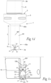
- Fig 1a
- is a perspective view of a milling tool according to a first embodiment of the present invention,
- Fig 1b
- is a lateral view of the milling tool of
Fig 1a , - Fig 1c
- is a front view of the milling tool of
Fig 1a , - Fig 1d
- is a lateral view from another direction of the milling tool of
Fig 1a , - Fig 1e
- is a lateral view in larger scale of a cutting part included in the milling tool of
Fig 1a , as seen from the same direction as inFig 1d , - Fig 1f
- is an exploded perspective view of the milling tool of
Fig 1a , - Figs 2a and 2b
- are perspective views from different directions of a cutting insert included in the milling tool of
Fig 1a , - Fig 2c
- is a lateral view of the cutting insert of
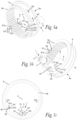
Figs 2a and 2b , - Figs 3a and 3b
- are perspective views from different directions of the milling tool of
Fig 1a and an internally toothed workpiece, as seen with the milling tool in a position for chamfering flank edges at a first end face of the workpiece, - Fig 3c
- is a front view of the milling tool and workpiece of
Figs 3a and 3b , - Fig 4a
- is a perspective view of the milling tool and workpiece of
Figs 3a-3c , as seen with the milling tool in a position for chamfering flank edges at an opposite second end face of the workpiece, - Fig 4b
- is a front view of the milling tool and workpiece of
Fig 4a , - Fig 5
- is a perspective view in larger scale of a part of the internally toothed workpiece of
Fig 3a , - Fig 6a
- is an end view in larger scale of a part of the internally toothed workpiece of
Fig 3a , as seen after a chamfering of the flank edges at the first end face of the workpiece, - Fig 6b
- is another end view in larger scale of a part of the internally toothed workpiece of
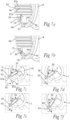
Fig 3a , as seen after a chamfering of the flank edges at the second end face of the workpiece, - Figs 7a-7h
- are schematic illustrations of different stages in a process of chamfering flank edges on an internally toothed workpiece by means of the milling tool of
Fig 1a , - Fig 8a
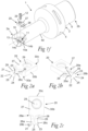
- is a perspective view of a milling tool according to a second embodiment of the invention,
- Fig 8b
- is a lateral view of the milling tool of
Fig 8a , - Figs 8c and 8d
- are exploded perspective views from different directions of the milling tool of
Fig 8a , - Fig 9a
- is a perspective view of a milling tool according to a third embodiment of the invention,
- Fig 9b
- is a front view of the milling tool of
Fig 9a , - Fig 9c
- is a lateral view of the milling tool of
Fig 9a , - Fig 9d
- is a lateral view from another direction of the milling tool of
Fig 9a , - Figs 9e and 9f
- are exploded perspective views from different directions of a part of the milling tool of
Fig 9a , - Fig 10a
- is a front view of a cutting insert included in the milling tool of
Fig 9a , - Fig 10b
- is a rear view of a cutting of
Fig 10a , - Fig 10c
- is a lateral view of the cutting insert of
Fig 10a , - Fig 10d
- is a planar view of the cutting insert of
Fig 10a , and - Fig 11
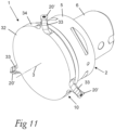
- is a perspective view of a milling tool according to a fourth embodiment of the invention.
- Different embodiments of a
milling tool 1 according to the present invention are illustrated inFigs 1a-1f ,Figs 8a-8d ,Figs 9a-9f andFig 11 . Themilling tool 1 is intended to be used for chamfering flank edges of internal or external teeth on a cylindrical toothed workpiece at opposite end faces of the workpiece. Themilling tool 1 comprises atool body 2, which is configured to be rotated about an axis ofrotation 3. Thetool body 2 has afront end 2a and an oppositerear end 2b. In the illustrated embodiments, acollar 5 is provided on thetool body 2. Arear part 6 of thetool body 2 located between thecollar 5 and therear end 2b forms a connection member, through which thetool body 2 is mountable, directly or via an intermediate tool holder, to a rotating spindle or the similar of a machine, for instance a milling machine. - The
tool body 2 comprises a cuttingpart 10, which is located in front of therear part 6 as seen in the axial direction of the tool body and at a distance from therear part 6. A cuttinginsert 20, 20' provided with cuttingedges part 10. - The cutting
insert 20, 20' is provided with afirst cutting edge 21 and asecond cutting edge 22 extending in a common extension plane EP, which is parallel to a longitudinal plane LP through thetool body 2 containing the axis ofrotation 3. Thefirst cutting edge 21 and thesecond cutting edge 22 are located opposite each other on opposite sides of a radial plane RP that contains the axis ofrotation 3 and is perpendicular to said longitudinal plane LP and consequently also perpendicular to said extension plane EP. Each one of the first and second cutting edges 21, 22 has afront end rear end rear end 21b of thefirst cutting edge 21 is located closer to therear part 6 of the tool body than thefront end 21a of the first cutting edge, and therear end 22b of thesecond cutting edge 22 is located closer to therear part 6 of the tool body than thefront end 22a of the second cutting edge. Thefront end 21a of thefirst cutting edge 21 is located closer to said radial plane RP than therear end 21b of thefirst cutting edge 21, wherein the distance between thefirst cutting edge 21 and said radial plane RP is gradually increasing as seen in a direction along thefirst cutting edge 21 from thefront end 21a thereof to therear end 21b thereof. Thefront end 22a of thesecond cutting edge 22 is located closer to said radial plane RP than therear end 22b of thesecond cutting edge 22, wherein the distance between thesecond cutting edge 22 and said radial plane RP is gradually increasing as seen in a direction along thesecond cutting edge 22 from thefront end 22a thereof to therear end 22b thereof. - In the illustrated embodiments, the
first cutting edge 21 is substantially rectilinear and extends at an angle α1 to said radial plane RP and thesecond cutting edge 22 is substantially rectilinear and extends at an angle α2 to said radial plane RP. The first and second angles α1, α2 may differ from each other but are preferably equal or at least substantially equal. The first angle α1 and the second angle α2 are larger than or equal to 15° and smaller than 85°, preferably 20-80°. In the illustrated embodiments, the first angle α1 and the second angle α2 are both approximately 45°. - In the illustrated embodiments, the cutting
insert 20, 20' is also provided with athird cutting edge 23 and afourth cutting edge 24 extending in the same extension plane EP as the first and second cutting edges 21, 22. Thethird cutting edge 23 and thefourth cutting edge 24 are located opposite each other on opposite sides of said radial plane RP. Each one of the third and fourth cutting edges 23, 24 has afront end rear end rear end 23b of thethird cutting edge 23 is located closer to therear part 6 of the tool body than thefront end 23a of thethird cutting edge 23, and therear end 24a of thefourth cutting edge 24 is located closer to therear part 6 of the tool body than thefront end 24a of thefourth cutting edge 24. Therear end 23b of thethird cutting edge 23 is located closer to said radial plane RP than thefront end 23a of thethird cutting edge 23, wherein the distance between thethird cutting edge 23 and said radial plane RP is gradually increasing as seen in a direction along thethird cutting edge 23 from therear end 23b thereof to thefront end 23a thereof. Therear end 24b of thefourth cutting edge 24 is located closer to said radial plane RP than thefront end 24a of thefourth cutting edge 24, wherein the distance between thefourth cutting edge 24 and said radial plane RP is gradually increasing as seen in a direction along thefourth cutting edge 24 from therear end 24b thereof to thefront end 24a thereof. - The cutting
insert 20, 20' has arake face 25 with one or more rake surfaces for the cutting edges 21-24 of the cutting insert. This rake face 25 faces radially outward away from the axis ofrotation 3. In the illustrated embodiments, therake face 25 is planar and extends in the same, or at least substantially the same, extension plane EP as the cutting edges 21-24. - The cutting
insert 20, 20' is also provided with clearance faces 26a, 26b, 26c, 26d associated with the cutting edges 21-24, wherein thefirst cutting edge 21 is formed at an intersection between therake face 25 and afirst clearance face 26a, thesecond cutting edge 22 is formed at an intersection between therake face 25 and asecond clearance face 26b, thethird cutting edge 23 is formed at an intersection between therake face 25 and athird clearance face 26c and thefourth cutting edge 24 is formed at an intersection between therake face 25 and afourth clearance face 26d. - In the illustrated embodiments, the
first cutting edge 21 and thesecond cutting edge 22 are mirror symmetrical to each other with respect to said radial plane RP, and also thethird cutting edge 23 and thefourth cutting edge 24 are mirror symmetrical to each other with respect to this radial plane RP. Furthermore, thefirst cutting edge 21 and thethird cutting edge 23 are here mirror symmetrical to each other with respect to a plane of symmetry PS (seeFigs 1e and9d ) that extends halfway between the first and third cutting edges 21, 23 perpendicularly to said radial plane RP and perpendicularly to said extension plane ES, wherein also thesecond cutting edge 22 and thefourth cutting edge 24 are mirror symmetrical to each other with respect to this plane of symmetry PS. - In the embodiments illustrated in
Figs 1a-1f and inFigs 8a-8d , the cuttinginsert 20 comprises abase part 27 and anextension arm 28 fixed to and projecting from thebase part 27. Theextension arm 28 has aninner end 28a facing thebase part 27 and an oppositeouter end 28b, wherein the cutting edges 21-24 and saidrake face 25 are arranged on theextension arm 28 at theouter end 28b thereof. In this case, the clearance faces 26a-26d are arranged on theextension arm 28 and provided on aperipheral surface 26 that extends around theextension arm 28 between theinner end 28a and theouter end 28b thereof. Theextension arm 28 suitably has a length of 1-20 mm, preferably 1-15 mm, and more preferably 3-9 mm. - The
base part 27 is configured to be received in aninsert seat 11 in the cuttingpart 10 and theextension arm 28 is configured to project from the cuttingpart 10 in radial direction in relation to the axis ofrotation 3 when the cuttinginsert 20 is mounted to the cuttingpart 10. Theinner end 28a of theextension arm 28 is preferably located at a longer distance from the axis ofrotation 3 than a radially outermost surface on the cuttingpart 10 when the cuttinginsert 20 is mounted to the cuttingpart 10. - The illustrated
cutting insert 20 is releasably fixed to theinsert seat 11 by means of afastening element 12 in the form of a screw, which extends through a throughhole 29 in the cuttinginsert 20 and is engaged in a threaded hole 13 (seeFig 1f ) in atangential support surface 14a in theinsert seat 11. Theinsert seat 11 is also provided with anaxial support surface 14b and aradial support surface 14c for supporting the cuttinginsert 20 when mounted in theinsert seat 11. Anaxial abutment surface 30b is provided on thebase part 27 of the cuttinginsert 20 and is configured to abut against theaxial support surface 14b in theinsert seat 11. Thebase part 27 is also provided with aradial abutment surface 30c, which is configured to abut against theradial support surface 14c in theinsert seat 11, and atangential abutment surface 30a, which is configured to abut against thetangential support surface 14a in theinsert seat 11. - In the embodiments illustrated in
Figs 1a-1f and inFigs 8a-8d , thetool body 2 comprises anelongated shank part 40, which carries the cuttingpart 10 and extends from the cutting part towards therear part 6. Theshank part 40 has afront end 40a facing the cuttingpart 10 and an oppositerear end 40b facing thecollar 5 and therear part 6. The cuttingpart 10 is fixed to theshank part 40 at thefront end 40a thereof. Theshank part 40 has aperipheral surface 41, which extends around theshank part 40 between therear end 40b and thefront end 40a thereof. Theshank part 40 has a longitudinal central axis that coincides with an axis ofrotation 3 of thetool body 2. Theinner end 28a of theextension arm 28 is located at a longer distance from the axis ofrotation 3 than a radially outermost part of theperipheral surface 41 of theshank part 40 when the cuttinginsert 20 is mounted in theinsert seat 11 of the cuttingpart 10. - In the illustrated embodiments, the
shank part 40 is rod-shaped and has the form of a right circular cylinder. However, theshank part 40 may also have any other suitable shape. Theshank part 40 may have a length L of 50-200 mm, preferably 100-150 mm. - In the embodiment illustrated in
Figs 1a-1f , the cuttingpart 10 and theshank part 40 are formed in one piece. - In the embodiment illustrated in
Figs 8a-8d , the cuttingpart 10 is detachably mounted to theshank part 40 at thefront end 40a thereof by means offastening elements 42 in the form of two screws, which extend through a respective throughhole 15 in the cuttingpart 10 and are engaged in a respective threadedhole 43 provided in a front end face 44 of theshank part 40. - In the embodiment illustrated in
Figs 8a-8d , the cuttingpart 10 is slidably mounted to theshank part 40 at thefront end 40a thereof so as to be linearly slidable in relation to theshank part 40 perpendicularly to the axis ofrotation 3 and in the longitudinal direction of theextension arm 28, wherein the cuttingpart 10 is lockable to theshank part 40 in different sliding positions in relation to theshank part 40 to thereby allow an adjustment of the radial distance between the above-mentioned extension plane EP and the axis ofrotation 3. In the illustrated example, arear face 16 of the cuttingpart 10 is provided with mutuallyparallel splines 17, which extend in parallel with a longitudinal axis of theextension arm 28 and which are in slidable engagement withcorresponding splines 47 provided on the front end face 44 of theshank part 40 in order to allow the cuttingpart 10 to slide in the desired direction in relation to theshank part 40 during the adjustment of the sliding position of the cuttingpart 10 in relation to theshank part 40. - The
milling tool 1 illustrated inFigs 8a-8d comprises anadjustment mechanism 50, by means of which the sliding position of the cuttingpart 10 in relation to theshank part 40 is adjustable. Thus, the exact positioning of the cuttingpart 10 along thesplines 47 on the front end face 44 of theshank part 40 is adjustable by means of theadjustment mechanism 50. In the illustrated embodiment, theadjustment mechanism 50 comprises anadjustment element 51, which is configured to act between the cuttingpart 10 and theshank part 40. Thisadjustment element 51 comprises apin 52, which is rotatably received in ahole 46 provided in the front end face 44 of theshank part 40, and ahead 53, which is fixed to thepin 52 and rotatably received in arecess 18 provided in therear face 16 of the cuttingpart 10. The axis of rotation of thepin 52 is parallel to but offset from the axis of rotation of thehead 53 such that a rotation of thehead 53 in therecess 18 will effect a sliding movement of the cuttingpart 10 in the longitudinal direction of thesplines socket 54 designed for releasable engagement with a torque tool (not shown) is provided in a front face of thehead 53 so as to allow a torque tool to be connected to thehead 53 when thehead 53 is to be rotated in order to make it move the cuttingpart 10 in the longitudinal direction of thesplines socket 54 is accessible through a hole in the cuttingpart 10. Each one of the throughholes 15 has an elongated cross-sectional shape with a longer axis extending substantially in the longitudinal direction of thesplines 17 to thereby allow the cuttingpart 10 to move perpendicularly to theshafts 42a of thefastening elements 42 in the longitudinal direction of thesplines 47 on the front end face 44 of theshank part 40. The cuttingpart 10 is lockable to theshank part 40 in a desired sliding position in relation to theshank part 40 by tightening of thefastening elements 42. Theadjustment mechanism 50 may of course also be designed in any other suitable manner. - In the embodiment illustrated in
Figs 9a-9f , the cuttingpart 10 comprises a disc-shaped orcylindrical base 32 with a central axis that coincides with the axis ofrotation 3. In this case, the cuttingpart 10 also comprises anextension arm 33, which is fixed to thebase 32 and projects from aperipheral surface 34 of the base 32 in radial direction in relation to the axis ofrotation 3. Theextension arm 33 has aninner end 33a facing thebase 32 and an oppositeouter end 33b. Theextension arm 33 is fixed to the base 32 at itsinner end 33a and the cutting insert 20' is mounted to theextension arm 33 at theouter end 33b thereof. Theextension arm 33 has such a length that the radial distance between the above-mentioned extension plane EP and a radially outermost part of thebase 32, i.e. theperipheral surface 34, is 5-40 mm, preferably 7-30 mm, and more preferably 9-22 mm. - The cutting
part 10 may comprises two or moresuch extension arms 33 evenly or at least substantially evenly distributed about the central axis of the base 32 with an equal angular distance between every twoconsecutive extension arms 33, as illustrated inFig 11 where the cuttingpart 10 is provided with threeextension arms 33. In this case, the number of cutting inserts 20' of themilling tool 1 corresponds to the number ofextension arms 33, wherein each cutting insert 20' is mounted to a respective one of theextension arms 33 at theouter end 33b thereof. - In the embodiment illustrated in
Figs 9a-9f , the cutting insert 20' is releasably mounted to aninsert seat 35 provided at theouter end 33b of theextension arm 33. The illustrated cutting insert 20' is releasably fixed to theinsert seat 35 by means of afastening element 36 in the form of a screw, which extends through a throughhole 29 in the cutting insert 20' and is engaged in a threadedhole 39 in asupport surface 37 in theinsert seat 35. Thesupport surface 37 is with advantage provided withsplines 38 or the similar configured for positive mechanical engagement withcorresponding splines 31 on an underside of the cutting insert 20' in order to ensure a correct positioning of the cutting insert 20' in theinsert seat 35 and prevent the cutting insert 20' from moving in relation to thesupport surface 37 when properly mounted to theinsert seat 35. - As mentioned above, the
milling tool 1 is intended to be used for chamfering flank edges 61-64 (seeFigs 5 and 6 ) of internal orexternal teeth 60 on a cylindricaltoothed workpiece 8 at afirst end face 9a of the workpiece and at an oppositesecond end face 9b of the workpiece. Eachtooth 60 on theworkpiece 8 has atooth tip 65, atooth root 66, a firsttooth flank surface 67a extending between thetooth tip 65 and thetooth root 66 on a first side of the tooth and a secondtooth flank surface 67b extending between thetooth tip 65 and thetooth root 66 on an opposite second side of the tooth. Afirst flank edge 61 is formed at an intersection between the firsttooth flank surface 67a and thefirst end face 9a of theworkpiece 8, asecond flank edge 62 is formed at an intersection between the secondtooth flank surface 67b and thefirst end face 9a of theworkpiece 8, athird flank edge 63 is formed at an intersection between the firsttooth flank surface 67a and thesecond end face 9b of theworkpiece 8 and afourth flank edge 64 is formed at an intersection between the secondtooth flank surface 67b and thesecond end face 9b of theworkpiece 8. Abottom land 68 is provided between thetooth roots 66 of every twoadjacent teeth 60 and atop land 69 is provided at thetooth tip 65 of eachtooth 60. - The
edges 70 at the interfaces between thetop land 69 of eachtooth 60 on theworkpiece 8 and therespective end face milling tool 1. - During the performance of a chamfering operation with the use of the
milling tool 1, theworkpiece 8 is attached to a rotatable workpiece holder (not shown) of a machine and rotatable by the machine about acentral axis 4 of theworkpiece 8, wherein themilling tool 1 is attached to a rotatable tool holder (not shown) of the machine and rotatable by the machine about the axis ofrotation 3 of thetool body 2 and moveable by the machine in relation to theworkpiece 8 in the axial direction z of theworkpiece 8 with the axis ofrotation 3 of thetool body 2 in parallel with thecentral axis 4 of theworkpiece 8. The speed of rotation of theworkpiece 8, the speed of rotation of themilling tool 1 and the movements of themilling tool 1 in relation to theworkpiece 8 are controlled in a program-controlled manner by means of an electronic control device (not shown). - The workpiece holder and the tool holder of the machine are normally located opposite to each other with the tool holder facing the workpiece holder. In the examples illustrated in
Figs 3-4 , the end face of theworkpiece 8 referred to as thefirst end face 9a is facing the tool holder of the machine, wherein the oppositesecond end face 9b of theworkpiece 8 is facing the workpiece holder of the machine. - When mounted to the workpiece holder of the machine, the
workpiece 8 is rotatable by the machine about itscentral axis 4 in a first direction of rotation R1 and in an opposite second direction of rotation R2. When theworkpiece 8 is positioned with thesecond end face 9b of theworkpiece 8 facing the workpiece holder (as illustrated inFigs 3-4 ), theworkpiece 8 will be rotated with the second tooth flank surfaces 67b of theteeth 60 on the workpiece as leading tooth flank surfaces and with the first tooth flank surfaces 67a of theteeth 60 on the workpiece as trailing tooth flank surfaces when rotated in the first direction of rotation R1, and with the first tooth flank surfaces 67a of theteeth 60 on the workpiece as leading tooth flank surfaces and with the second tooth flank surfaces 67b of theteeth 60 on the workpiece as trailing tooth flank surfaces when rotated in the second direction of rotation R2. - In order to perform a chamfering of the first and second flank edges 61, 62 of the
teeth 60 on theworkpiece 8, the following steps are performed: - a) the
milling tool 1 is positioned in a first predefined position in relation to theworkpiece 8 with the axis ofrotation 3 of thetool body 2 in parallel with thecentral axis 4 of theworkpiece 8 and with the cuttingpart 10 of thetool body 2 adjacent to thefirst end face 9a of theworkpiece 8 and with the first and second cutting edges 21, 22 facing thisend face 9a, as illustrated inFigs 3a and 3b ; - b) the
workpiece 8 is rotated about itscentral axis 4 in a direction of rotation R1 with the second tooth flank surfaces 67b as leading tooth flank surfaces and with the first tooth flank surfaces 67a as trailing tooth flank surfaces and themilling tool 1 is simultaneously rotated about the axis ofrotation 3 of thetool body 2, with a predefined relationship between the speed of rotation of themilling tool 1 and the speed of rotation of theworkpiece 8, in the same direction of rotation R1 as theworkpiece 8 when saidteeth 60 are internal teeth on the workpiece 8 (seeFigs 3a-3c ) or in an opposite direction of rotation R2 when saidteeth 60 are external teeth on theworkpiece 8, while keeping the axis ofrotation 3 of thetool body 2 in parallel with thecentral axis 4 of theworkpiece 8 and with thefirst cutting edge 21 as leading cutting edge and thesecond cutting edge 22 as trailing cutting edge such that thefirst cutting edge 21 chamfers a part of thefirst flank edge 61 of saidteeth 60 from thetooth tip 65 towards thetooth root 66 of eachtooth 60; - c) the
milling tool 1 is positioned in a second predefined position in relation to theworkpiece 8 with the axis ofrotation 3 of thetool body 2 in parallel with thecentral axis 4 of theworkpiece 8 and with the cuttingpart 10 of thetool body 2 adjacent to thefirst end face 9a of theworkpiece 8 and with the first and second cutting edges 21, 22 facing thisend face 9a; and - d) the
workpiece 8 is rotated about itscentral axis 4 in a direction of rotation R2 with the first tooth flank surfaces 67a as leading tooth flank surfaces and the second tooth flank surfaces 67b as trailing tooth flank surfaces and themilling tool 1 is simultaneously rotated about the axis ofrotation 3 of thetool body 2, with a predefined relationship between the speed of rotation of themilling tool 1 and the speed of rotation of theworkpiece 8, in the same direction of rotation R2 as theworkpiece 8 when saidteeth 60 are internal teeth on theworkpiece 8 or in an opposite direction of rotation R1 when saidteeth 60 are external teeth on theworkpiece 8, while keeping the axis ofrotation 3 of thetool body 2 in parallel with thecentral axis 4 of theworkpiece 8 and with thesecond cutting edge 22 as leading cutting edge and thefirst cutting edge 21 as trailing cutting edge such that thesecond cutting edge 22 chamfers a part of thesecond flank edge 62 of saidteeth 60 from thetooth tip 65 towards thetooth root 66 of eachtooth 60. - In order to perform a chamfering also of the third and fourth flank edges 63, 64 of the
teeth 60 on theworkpiece 8, the following additional steps are performed: - e) the
milling tool 1 is positioned in a third predefined position in relation to theworkpiece 8 with the axis ofrotation 3 of thetool body 2 in parallel with thecentral axis 4 of theworkpiece 8 and with the cuttingpart 10 of thetool body 2 adjacent to thesecond end face 9b of theworkpiece 8 and with the third and fourth cutting edges 23, 24 facing thisend face 9b, as illustrated inFigs 4a and 4b ; - f) the
workpiece 8 is rotated about itscentral axis 4 in a direction of rotation R1 with the second tooth flank surfaces 67b as leading tooth flank surfaces and with the first tooth flank surfaces 67a as trailing tooth flank surfaces and themilling tool 1 is simultaneously rotated about the axis ofrotation 3 of thetool body 2, with a predefined relationship between the speed of rotation of themilling tool 1 and the speed of rotation of theworkpiece 8, in the same direction of rotation R1 as theworkpiece 8 when saidteeth 60 are internal teeth on the workpiece 8 (seeFigs 4a -4c) or in an opposite direction of rotation R2 when saidteeth 60 are external teeth on theworkpiece 8, while keeping the axis ofrotation 3 of thetool body 2 in parallel with thecentral axis 4 of theworkpiece 8 and with thethird cutting edge 23 as leading cutting edge and thefourth cutting edge 24 as trailing cutting edge such that thethird cutting edge 23 chamfers a part of thethird flank edge 63 of saidteeth 60 from thetooth tip 65 towards thetooth root 66 of eachtooth 60; - g) the
milling tool 1 is positioned in a fourth predefined position in relation to theworkpiece 8 with the axis ofrotation 3 of thetool body 2 in parallel with thecentral axis 4 of theworkpiece 8 and with the cuttingpart 10 of thetool body 2 adjacent to thesecond end face 9b of theworkpiece 8 and with the third and fourth cutting edges 23, 24 facing thisend face 9b; and - h) the
workpiece 8 is rotated about itscentral axis 4 in a direction of rotation R2 with the first tooth flank surfaces 67a as leading tooth flank surfaces and the second tooth flank surfaces 67b as trailing tooth flank surfaces and themilling tool 1 is simultaneously rotated about the axis ofrotation 3 of thetool body 2, with a predefined relationship between the speed of rotation of themilling tool 1 and the speed of rotation of theworkpiece 8, in the same direction of rotation R2 as theworkpiece 8 when saidteeth 60 are internal teeth on theworkpiece 8 or in an opposite direction of rotation R1 when saidteeth 60 are external teeth on theworkpiece 8, while keeping the axis ofrotation 3 of thetool body 2 in parallel with thecentral axis 4 of theworkpiece 8 and with thefourth cutting edge 24 as leading cutting edge and thethird cutting edge 23 as trailing cutting edge such that thefourth cutting edge 24 chamfers a part of thefourth flank edge 64 of saidteeth 60 from thetooth tip 65 towards thetooth root 66 of eachtooth 60. - During the chamfering in each one of the above-mentioned steps b, d, f and h, a part of the active one of the cutting edges 21-24 is rotated into a gap between two
adjacent teeth 60 and is thereafter moved together with this gap in the direction of rotation of theworkpiece 8 during a part of a revolution of theworkpiece 8, while coming into cutting engagement with a part of one of the flank edges that are located on opposite sides of the gap, before being rotated out of the gap, as illustrated inFigs 7a-7i . Upon continued rotation of themilling tool 1, a part of the active one of the cutting edges 21-24 is rotated into a new gap between two otheradjacent teeth 60 on theworkpiece 8, and so on. The position of themilling tool 1 in relation to theworkpiece 8 and the rotation of themilling tool 1 in relation to the rotation of theworkpiece 8 are to be so adapted that the active one of the cutting edges 21-24 in each one of steps b, d, f and h will make contact with eachflank edge tooth tip 65 and thereafter will move, in cutting engagement, along a part of theflank edge tooth root 66 while chamfering this part pf the flank edge, as illustrated inFigs 7c-7g . - The relationship between the speed of rotation of the
milling tool 1 and the speed of rotation of theworkpiece 8 is to be so adapted in each one of the above-mentioned steps b, d, f and h that a part of the active one of the cutting edges 21-24 has entered the gaps between allteeth 60 on theworkpiece 8 after a certain number of revolutions of theworkpiece 8. In order to allow the active cutting edge to move in the same direction as the gap between twoadjacent teeth 60 on theworkpiece 8 with a part of the cutting edge received in the gap in question, themilling tool 1 has to be rotated about the axis ofrotation 3 of thetool body 2 in the same direction of rotation as theworkpiece 8 when flank edges 61-64 ofinternal teeth 60 on a workpiece are being chamfered and in a direction of rotation that is opposite to the direction of rotation of theworkpiece 8 when flank edges 61-64 ofexternal teeth 60 on a workpiece are being chamfered. - During the chamfering in each one of the above-mentioned steps b, d, f and h, the axis of
rotation 3 of thetool body 2 is maintained in a fixed position in relation to thecentral axis 4 of theworkpiece 8, as seen in a plane x, y perpendicular to thecentral axis 4 of theworkpiece 8. However, themilling tool 1 may be moved in relation to theworkpiece 8 in the axial direction z of the workpiece in each one of steps b and d, to thereby gradually move thefirst cutting edge 21 in a direction towards thefirst end face 9a of theworkpiece 8 during the chamfering of the first flank edges 61 in step b and gradually move thesecond cutting edge 22 in a direction towards thefirst end face 9a of theworkpiece 8 during the chamfering of the second flank edges 62 in step d, wherein each one of the first flank edges 61 is chamfered by thefirst cutting edge 21 in several consecutive cuts in step b and each one of the second flank edges 62 is chamfered by thesecond cutting edge 22 in several consecutive cuts in step d. Themilling tool 1 may also be moved in relation to theworkpiece 8 in the axial direction z of the workpiece in each one of steps f and h, to thereby gradually move thethird cutting edge 23 in a direction towards thesecond end face 9b of theworkpiece 8 during the chamfering of the third flank edges 63 in step f and gradually move thefourth cutting edge 24 in a direction towards thesecond end face 9b of theworkpiece 8 during the chamfering of the fourth flank edges 64 in step h, wherein each one of the third flank edges 63 is chamfered by thethird cutting edge 23 in several consecutive cuts in step b and each one of the second flank edges 62 is chamfered by thesecond cutting edge 22 in several consecutive cuts in step d. As an alternative, themilling tool 1 may remain in a fixed position in relation to theworkpiece 8, as seen in the axial direction z of the workpiece, during the chamfering in steps b, d, f and h, wherein each individual flank edge 61-64 is chamfered by the active one of the cutting edges 21-24 in one single cut. - During the chamfering in steps b, d, f and h, the axis of
rotation 3 of thetool body 2 has to be in such a position in relation to theworkpiece 8 that therake face 25 is prevented from hitting the bottom lands 68 adjacent to the flank edges that are being chamfered. It is therefore not possible, with themilling tool 1 according to the present invention, to chamfer the flank edges 61-64 along the entire length thereof. On the contrary, the chamfering of an individual flank edge 61-64 has to be ended at a distance from the adjacentbottom land 68, as illustrated inFigs 6a and 6b . - The invention is of course not in any way restricted to the embodiments described above. On the contrary, many possibilities to modifications thereof will be apparent to a person with ordinary skill in the art without departing from the basic idea of the invention such as defined in the appended claims.
Claims (23)
- A milling tool for chamfering flank edges (61-64) of internal or external teeth (60) on a cylindrical toothed workpiece (8) at at least one of two opposite end faces (9a, 9b) of the workpiece (8), the milling tool (1) comprising:- a tool body (2), which at a rear end (2b) has a rear part (6) configured for attachment to a machine in order to allow the tool body (2) to be rotated by the machine about an axis of rotation (3) of the tool body (2), wherein the tool body (2) comprises a cutting part (10) located in front of the rear part (6) as seen in an axial direction of the tool body (2); and- at least one cutting insert (20, 20') mounted to the cutting part (10),characterized in:- that said at least one cutting insert (20, 20') is provided with at least a first cutting edge (21) and a second cutting edge (22) extending in a common extension plane (EP), which is parallel to a longitudinal plane (LP) that contains the axis of rotation (3), wherein the first cutting edge (21) and the second cutting edge (22) are located opposite each other on opposite sides of a radial plane (RP) that contains the axis of rotation (3) and is perpendicular to said longitudinal plane (LP), and wherein:• the first cutting edge (21) has a rear end (21b) and an opposite front end (21a), the rear end (21b) of the first cutting edge (21) being located closer to the rear part (6) of the tool body than the front end (21a) of the first cutting edge (21), wherein the front end (21a) of the first cutting edge (21) is located closer to said radial plane (RP) than the rear end (21b) of the first cutting edge (21) and the distance between the first cutting edge (21) and said radial plane (RP) is gradually increasing as seen in a direction along the first cutting edge (21) from the front end (21a) thereof to the rear end (21b) thereof, and• the second cutting edge (22) has a rear end (22b) and an opposite front end (22a), the rear end (22b) of the second cutting edge (22) being located closer to the rear part (6) of the tool body than the front end (22a) of the second cutting edge (22), wherein the front end (22a) of the second cutting edge (22) is located closer to said radial plane (RP) than the rear end (22b) of the second cutting edge (22) and the distance between the second cutting edge (22) and said radial plane (RP) is gradually increasing as seen in a direction along the second cutting edge (22) from the front end (22a) thereof to the rear end (22b) thereof; and- that said at least one cutting insert (20, 20') has a rake face (25) with one or more rake surfaces for the first and second cutting edges (21, 22), wherein this rake face (25) faces radially outward away from the axis of rotation (3).
- A milling tool according to claim 1, characterized in that said rake face (25) is planar and extends in the same extension plane (EP) as the first and second cutting edges (21, 22).
- A milling tool according to claim 1 or 2, characterized in:- that the first cutting edge (21) is substantially rectilinear and extends at an angle (α1) to said radial plane (RP) that is larger than or equal to 15° and smaller than 85°, preferably 20-80°; and- that the second cutting edge (22) is substantially rectilinear and extends at an angle (α2) to said radial plane (RP) that is larger than or equal to 15° and smaller than 85°, preferably 20-80°.
- A milling tool according to any of claims 1-3, characterized in that the first cutting edge (21) and the second cutting edge (22) are mirror symmetrical to each other with respect to said radial plane (RP).
- A milling tool according to any of claims 1-4, characterized in:- that said at least one cutting insert (20, 20') is also provided with a third cutting edge (23) and a fourth cutting edge (24) extending in the same extension plane (EP) as the first and second cutting edges (21, 22), wherein the third cutting edge (23) and the fourth cutting edge (24) are located opposite each other on opposite sides of said radial plane (RP), and wherein:• the third cutting edge (23) has a rear end (23b) and an opposite front end (23a), the rear end (23b) of the third cutting edge (23) being located closer to the rear part (6) of the tool body than the front end (23a) of the third cutting edge (23), wherein the rear end (23b) of the third cutting edge (23) is located closer to said radial plane (RP) than the front end (23a) of the third cutting edge (23) and the distance between the third cutting edge (23) and said radial plane (RP) is gradually increasing as seen in a direction along the third cutting edge (23) from the rear end (23b) thereof to the front end (23a) thereof, and• the fourth cutting edge (24) has a rear end (24b) and an opposite front end (24a), the rear end (24b) of the fourth cutting edge (24) being located closer to the rear part (6) of the tool body than the front end (24a) of the fourth cutting edge (24), wherein the rear end (24b) of the fourth cutting edge (24) is located closer to said radial plane (RP) than the front end (24a) of the fourth cutting edge (24) and the distance between the fourth cutting edge (24) and said radial plane (RP) is gradually increasing as seen in a direction along the fourth cutting edge (24) from the rear end (24b) thereof to the front end (24a) thereof; and- that said rake face (25) is provided with one or more rake surfaces also for the third and fourth cutting edges (23, 24).
- A milling tool according to claim 5, characterized in that the third cutting edge (23) and the fourth cutting edge (24) are mirror symmetrical to each other with respect to said radial plane (RP).
- A milling tool according to claim 5 or 6, characterized in:- that the first cutting edge (21) and the third cutting edge (23) are mirror symmetrical to each other with respect to a plane of symmetry (PS) that extends halfway between the first and third cutting edges (21, 23) perpendicularly to said radial plane (RP) and perpendicularly to said extension plane (EP); and- that also the second cutting edge (22) and the fourth cutting edge (24) are mirror symmetrical to each other with respect to said plane of symmetry (PS).
- A milling tool according to any of claims 5-7, characterized in that said at least one cutting insert (20) comprises a base part (27) and an extension arm (28) fixed to and projecting from the base part (27), wherein the extension arm (28) has an inner end (28a) facing the base part (27) and an opposite outer end (28b), said cutting edges (21-24) and said rake face (25) being arranged on the extension arm (28) at the outer end (28b) thereof, and wherein the base part (27) is configured to be received in an insert seat (11) in the cutting part (10) and the extension arm (28) is configured to project from the cutting part (10) in radial direction in relation to the axis of rotation (3) when the cutting insert (20) is mounted to the cutting part (10).
- A milling tool according to claim 8, characterized in that the extension arm (28) has a length of 1-20 mm, preferably 1-15 mm, more preferably 3-9 mm.
- A milling tool according to claim 8 or 9, characterized in:- that the tool body (2) comprises an elongated shank part (40), which carries the cutting part (10) and extends from the cutting part (10) towards the rear part (6) and which has a front end (40a) facing the cutting part (10), an opposite rear end (40b) and a peripheral surface (41) extending around the shank part (40) between the rear end (40b) and the front end (40a) thereof, wherein the shank part (40) has a longitudinal central axis that coincides with the axis of rotation (3) of the tool body (2); and- that the inner end (28a) of the extension arm (28) is located at a longer distance from the axis of rotation (3) than a radially outermost part of the peripheral surface (41) of the shank part (40) when the cutting insert (20) is mounted to the cutting part (10).
- A milling tool according to claim 10, characterized in that the cutting part (10) is slidably mounted to the shank part (40) at the front end (40a) thereof so as to be linearly slidable in relation to the shank part (40) perpendicularly to the axis of rotation (3) and in a longitudinal direction of the extension arm (28), wherein the cutting part (10) is lockable to the shank part (40) in different sliding positions in relation to the shank part (40) to thereby allow an adjustment of the radial distance between said extension plane (EP) and the axis of rotation (3).
- A milling tool according to claim 10, characterized in that the cutting part (10) and the shank part (40) are formed in one piece.
- A milling tool according to any of claims 10-12, characterized in that the shank part (40) is rod-shaped.
- A milling tool according to any of claims 10-13, characterized in that the shank part (40) has a length (L) of 50-200 mm, preferably 100-150 mm.
- A milling tool according to any of claims 5-7, characterized in that the cutting part (10) comprises a disc-shaped or cylindrical base (32) with a central axis that coincides with the axis of rotation (3) and at least one extension arm (33) fixed to the base (32) and projecting from the base (32) in radial direction in relation to the axis of rotation (3), wherein the extension arm (33) has an inner end (33a) facing the base (32) and an opposite outer end (33b), said at least one cutting insert (20') being mounted to the extension arm (33) at the outer end (33b) thereof.
- A milling tool according to claim 15, characterized in that the radial distance between said extension plane (EP) and a radially outermost part of the base (32) is 5-40 mm, preferably 7-30 mm, more preferably 9-22 mm.
- A milling tool according to claim 15 or 16, characterized in that said at least one cutting insert (20') is releasably mounted to an insert seat (35) provided at the outer end (33b) of the associated extension arm (33).
- A milling tool according to any of claims 15-17, characterized in that the cutting part (10) comprises two or more such extension arms (33) evenly or at least substantially evenly distributed about the central axis of the base (32), wherein the number of cutting inserts (20') of the milling tool (1) corresponds to the number of extension arms (33), each cutting insert (20') being mounted to a respective one of the extension arms (33) at the outer end (33b) thereof.
- A method for chamfering flank edges of internal or external teeth (60) on a cylindrical toothed workpiece (8) at at least one of two opposite end faces (9a, 9b) of the workpiece (8), wherein each one of said teeth (60) has a tooth tip (65), a tooth root (66), a first tooth flank surface (67a) extending between the tooth tip (65) and the tooth root (66) on a first side of the tooth and a second tooth flank surface (67b) extending between the tooth tip (65) and the tooth root (66) on an opposite second side of the tooth, a first flank edge (61) being formed at an intersection between the first tooth flank surface (67a) and a first one (9a) of the two end faces of the workpiece (8) and a second flank edge (62) being formed at an intersection between the second tooth flank surface (67b) and said first one (9a) of the two end faces of the workpiece (8), wherein the workpiece (8) is rotatable by a machine about a central axis (4) of the workpiece (8) and wherein the chamfering is performed by means of a milling tool (1) according to any of claims 1-18, which is rotatable by the machine about the axis of rotation (3) of the tool body (2), the method comprising the following steps:a) positioning the milling tool (1) in a first predefined position in relation to the workpiece (8) with the axis of rotation (3) of the tool body (2) in parallel with the central axis (4) of the workpiece (8) and with the cutting part (10) of the tool body (2) adjacent to said first one (9a) of the two end faces of the workpiece (8) and with the first and second cutting edges (21, 22) facing this end face (9a);b) rotating the workpiece (8) about its central axis (4) in a direction of rotation (R1) with the second tooth flank surfaces (67b) as leading tooth flank surfaces and the first tooth flank surfaces (67a) as trailing tooth flank surfaces and simultaneously rotating the milling tool (1) about the axis of rotation (3) of the tool body (2), with a predefined relationship between the speed of rotation of the milling tool (1) and the speed of rotation of the workpiece (8), in the same direction of rotation (R1) as the workpiece (8) when said teeth (60) are internal teeth on the workpiece (8) or in an opposite direction of rotation (R2) when said teeth (60) are external teeth on the workpiece (8), while keeping the axis of rotation (3) of the tool body (2) in parallel with the central axis (4) of the workpiece (8) and with the first cutting edge (21) as leading cutting edge and the second cutting edge (22) as trailing cutting edge such that the first cutting edge (21) chamfers at least a part of the first flank edge (61) of said teeth (60) from the tooth tip (65) towards the tooth root (66) of each tooth (60);c) positioning the milling tool (1) in a second predefined position in relation to the workpiece (8) with the axis of rotation (3) of the tool body (2) in parallel with the central axis (4) of the workpiece (8) and with the cutting part (10) of the tool body (2) adjacent to said first one (9a) of the two end faces of the workpiece (8) and with the first and second cutting edges (21, 22) facing this end face (9a); andd) rotating the workpiece (8) about its central axis (4) in a direction of rotation (R2) with the first tooth flank surfaces (67a) as leading tooth flank surfaces and the second tooth flank surfaces (67b) as trailing tooth flank surfaces and simultaneously rotating the milling tool (1) about the axis of rotation (3) of the tool body (2), with a predefined relationship between the speed of rotation of the milling tool (1) and the speed of rotation of the workpiece (8), in the same direction of rotation (R2) as the workpiece (8) when said teeth (60) are internal teeth on the workpiece (8) or in an opposite direction of rotation (R1) when said teeth (60) are external teeth on the workpiece (8), while keeping the axis of rotation (3) of the tool body (2) in parallel with the central axis (4) of the workpiece (8) and with the second cutting edge (22) as leading cutting edge and the first cutting edge (21) as trailing cutting edge such that the second cutting edge (22) chamfers at least a part of the second flank edge (62) of said teeth (60) from the tooth tip (65) towards the tooth root (66) of each tooth (60).
- A method according to claim 19, wherein:- the milling tool (1) is moved in relation to the workpiece (8) in axial direction (z) in step b to thereby gradually move the first cutting edge (21) in a direction towards said first one (9a) of the two end faces of the workpiece (8) during the chamfering of the first flank edges (61) of said teeth (60); and- the milling tool (1) is moved in relation to the workpiece (8) in axial direction (z) in step d to thereby gradually move the second cutting edge (22) in a direction towards said first one (9a) of the two end faces of the workpiece (8) during the chamfering of the second flank edges (62) of said teeth (60).
- A method according to claim 19 or 20, wherein a third flank edge (63) is formed at an intersection between the first tooth flank surface (67a) of each one of said teeth (60) and a second one (9b) of the two end faces of the workpiece (8) and a fourth flank edge (64) is formed at an intersection between the second tooth flank surface (67b) of each one of said teeth (60) and said second one (9b) of the two end faces of the workpiece (8), and wherein said milling tool (1) is a milling tool according to any of claims 5-18, the method comprising the following additional steps:e) positioning the milling tool (1) in a third predefined position in relation to the workpiece (8) with the axis of rotation (3) of the tool body (2) in parallel with the central axis (4) of the workpiece (8) and with the cutting part (10) of the tool body (2) adjacent to said second one (9b) of the two end faces of the workpiece (8) and with the third and fourth cutting edges (23, 24) facing this end face (9b);f) rotating the workpiece (8) about its central axis (4) in a direction of rotation (R1) with the second tooth flank surfaces (67b) as leading tooth flank surfaces and the first tooth flank surfaces (67a) as trailing tooth flank surfaces and simultaneously rotating the milling tool (1) about the axis of rotation (3) of the tool body (2), with a predefined relationship between the speed of rotation of the milling tool (1) and the speed of rotation of the workpiece (8), in the same direction of rotation (R1) as the workpiece (8) when said teeth (60) are internal teeth on the workpiece (8) or in an opposite direction of rotation (R2) when said teeth (60) are external teeth on the workpiece (8), while keeping the axis of rotation (3) of the tool body (2) in parallel with the central axis (4) of the workpiece (8) and with the third cutting edge (23) as leading cutting edge and the fourth cutting edge (24) as trailing cutting edge such that the third cutting edge (23) chamfers at least a part of the third flank edge (63) of said teeth (60) from the tooth tip (65) towards the tooth root (66) of each tooth (60);g) positioning the milling tool (1) in a fourth predefined position in relation to the workpiece (8) with the axis of rotation (3) of the tool body (2) in parallel with the central axis (4) of the workpiece (8) and with the cutting part (10) of the tool body (2) adjacent to said second one (9b) of the two end faces of the workpiece (8) and with the third and fourth cutting edges (23, 24) facing this end face (9b); andh) rotating the workpiece (8) about its central axis (4) in a direction of rotation (R2) with the first tooth flank surfaces (67a) as leading tooth flank surfaces and the second tooth flank surfaces (67b) as trailing tooth flank surfaces and simultaneously rotating the milling tool (1) about the axis of rotation (3) of the tool body (2), with a predefined relationship between the speed of rotation of the milling tool (1) and the speed of rotation of the workpiece (8), in the same direction of rotation (R2) as the workpiece (8) when said teeth (60) are internal teeth on the workpiece (8) or in an opposite direction of rotation (R1) when said teeth (60) are external teeth on the workpiece (8), while keeping the axis of rotation (3) of the tool body (2) in parallel with the central axis (4) of the workpiece (8) and with the fourth cutting edge (24) as leading cutting edge and the third cutting edge (23) as trailing cutting edge such that the fourth cutting edge (24) chamfers at least a part of the fourth flank edge (64) of said teeth (60) from the tooth tip (65) towards the tooth root (66) of each tooth (60).
- A method according to claim 21, wherein:- the milling tool (1) is moved in relation to the workpiece (8) in axial direction (z) in step f to thereby gradually move the third cutting edge (23) in a direction towards said second one (9b) of the two end faces of the workpiece (8) during the chamfering of the third flank edges (63) of said teeth (60); and- the milling tool (1) is moved in relation to the workpiece (8) in axial direction (z) in step h to thereby gradually move the fourth cutting edge (24) in a direction towards said second one (9b) of the two end faces of the workpiece (8) during the chamfering of the fourth flank edges (64) of said teeth (60).
- A computer program having instructions which when executed by a CNC machine causes the CNC machine to perform the steps according to any of claims 19-22.
Priority Applications (3)
| Application Number | Priority Date | Filing Date | Title |
|---|---|---|---|
| EP22216751.2A EP4393624B1 (en) | 2022-12-27 | 2022-12-27 | Milling tool and method for chamfering flank edges of teeth on a cylindrical toothed workpiece |
| PCT/EP2023/082628 WO2024141205A1 (en) | 2022-12-27 | 2023-11-22 | Milling tool and method for chamfering flank edges of teeth on a cylindrical toothed workpiece |
| JP2025537173A JP2026506440A (en) | 2022-12-27 | 2023-11-22 | Milling tool and method for chamfering tooth relief edges on cylindrical toothed workpieces |
Applications Claiming Priority (1)
| Application Number | Priority Date | Filing Date | Title |
|---|---|---|---|
| EP22216751.2A EP4393624B1 (en) | 2022-12-27 | 2022-12-27 | Milling tool and method for chamfering flank edges of teeth on a cylindrical toothed workpiece |
Publications (2)
| Publication Number | Publication Date |
|---|---|
| EP4393624A1 true EP4393624A1 (en) | 2024-07-03 |
| EP4393624B1 EP4393624B1 (en) | 2025-06-11 |
Family
ID=84604236
Family Applications (1)
| Application Number | Title | Priority Date | Filing Date |
|---|---|---|---|
| EP22216751.2A Active EP4393624B1 (en) | 2022-12-27 | 2022-12-27 | Milling tool and method for chamfering flank edges of teeth on a cylindrical toothed workpiece |
Country Status (3)
| Country | Link |
|---|---|
| EP (1) | EP4393624B1 (en) |
| JP (1) | JP2026506440A (en) |
| WO (1) | WO2024141205A1 (en) |
Citations (2)
| Publication number | Priority date | Publication date | Assignee | Title |
|---|---|---|---|---|
| DE4400887A1 (en) * | 1994-01-14 | 1995-08-17 | Praewema Werkzeugmaschinenfabr | Milling machine for processing ridge edges on the end faces of teeth of a gear wheel |
| WO2022013068A1 (en) | 2020-07-13 | 2022-01-20 | Profilator Gmbh & Co. Kg | Device and method for producing chamfers on tooth flanks of gears, and cutting tool, cutting plate, and control program for same |
-
2022
- 2022-12-27 EP EP22216751.2A patent/EP4393624B1/en active Active
-
2023
- 2023-11-22 JP JP2025537173A patent/JP2026506440A/en active Pending
- 2023-11-22 WO PCT/EP2023/082628 patent/WO2024141205A1/en not_active Ceased
Patent Citations (2)
| Publication number | Priority date | Publication date | Assignee | Title |
|---|---|---|---|---|
| DE4400887A1 (en) * | 1994-01-14 | 1995-08-17 | Praewema Werkzeugmaschinenfabr | Milling machine for processing ridge edges on the end faces of teeth of a gear wheel |
| WO2022013068A1 (en) | 2020-07-13 | 2022-01-20 | Profilator Gmbh & Co. Kg | Device and method for producing chamfers on tooth flanks of gears, and cutting tool, cutting plate, and control program for same |
Also Published As
| Publication number | Publication date |
|---|---|
| JP2026506440A (en) | 2026-02-25 |
| WO2024141205A1 (en) | 2024-07-04 |
| EP4393624B1 (en) | 2025-06-11 |
Similar Documents
| Publication | Publication Date | Title |
|---|---|---|
| JP5902564B2 (en) | Milling tools and segments | |
| KR101746078B1 (en) | Machine tool and method for producing gearing | |
| CN100503112C (en) | Method for removing burrs, bevel gear cutting machine used therefor | |
| AU701071B2 (en) | Improved integral boring and threading tool and method | |
| US8113750B2 (en) | Face hob hypoid gear tooth cutting by common blades | |
| EP1603698A1 (en) | Tool and cutting insert for the fine turning of grooves in workpieces | |
| JP6963012B2 (en) | Milling tool | |
| US20130022424A1 (en) | Face hob hypoid gear tooth top-land radius by common chamfer tool | |
| EP1930109A2 (en) | Cup-shaped milling cutter for airfoils | |
| CN115916443B (en) | Equipment and methods for forming chamfers on the tooth surface of gears, as well as cutting tools, inserts and control programs for this purpose. | |
| CN108602145B (en) | Single Blade Bevel Gear Cutting Tools | |
| WO2017211427A1 (en) | Clamping system for an abutment blank | |
| JP2001347412A (en) | Front cutter and cutter blade | |
| EP4393624B1 (en) | Milling tool and method for chamfering flank edges of teeth on a cylindrical toothed workpiece | |
| WO2010101512A2 (en) | Method of thread milling, thread, and insert and tool for thread milling | |
| CN109414771B (en) | Cutting insert and indexable insert type rotary cutting tool | |
| JP4017377B2 (en) | Cutting tools | |
| WO2021019800A1 (en) | Skiving cutter and skiving device | |
| EP4368324A1 (en) | Milling tool and method for chamfering flank edges of teeth on a cylindrical toothed workpiece | |
| EP4368325A1 (en) | Method for chamfering flank edges of teeth on a cylindrical toothed workpiece | |
| CN113811410B (en) | Boring tool holders and turning tools | |
| JP3903717B2 (en) | Tapered hole machining method and tapered hole machining tool | |
| US20020083796A1 (en) | End mill type gear cutters for spindle driven machines | |
| CN116871571B (en) | Milling method for internal spline of blisk | |
| JP2003039221A (en) | Drilling method and boring tool |
Legal Events
| Date | Code | Title | Description |
|---|---|---|---|
| PUAI | Public reference made under article 153(3) epc to a published international application that has entered the european phase |
Free format text: ORIGINAL CODE: 0009012 |
|
| STAA | Information on the status of an ep patent application or granted ep patent |
Free format text: STATUS: THE APPLICATION HAS BEEN PUBLISHED |
|
| AK | Designated contracting states |
Kind code of ref document: A1 Designated state(s): AL AT BE BG CH CY CZ DE DK EE ES FI FR GB GR HR HU IE IS IT LI LT LU LV MC ME MK MT NL NO PL PT RO RS SE SI SK SM TR |
|
| STAA | Information on the status of an ep patent application or granted ep patent |
Free format text: STATUS: REQUEST FOR EXAMINATION WAS MADE |
|
| 17P | Request for examination filed |
Effective date: 20250103 |
|
| GRAP | Despatch of communication of intention to grant a patent |
Free format text: ORIGINAL CODE: EPIDOSNIGR1 |
|
| STAA | Information on the status of an ep patent application or granted ep patent |
Free format text: STATUS: GRANT OF PATENT IS INTENDED |
|
| INTG | Intention to grant announced |
Effective date: 20250226 |
|
| GRAS | Grant fee paid |
Free format text: ORIGINAL CODE: EPIDOSNIGR3 |
|
| P01 | Opt-out of the competence of the unified patent court (upc) registered |
Free format text: CASE NUMBER: APP_15472/2025 Effective date: 20250331 |
|
| GRAA | (expected) grant |
Free format text: ORIGINAL CODE: 0009210 |
|
| STAA | Information on the status of an ep patent application or granted ep patent |
Free format text: STATUS: THE PATENT HAS BEEN GRANTED |
|
| AK | Designated contracting states |
Kind code of ref document: B1 Designated state(s): AL AT BE BG CH CY CZ DE DK EE ES FI FR GB GR HR HU IE IS IT LI LT LU LV MC ME MK MT NL NO PL PT RO RS SE SI SK SM TR |
|
| REG | Reference to a national code |
Ref country code: GB Ref legal event code: FG4D |
|
| REG | Reference to a national code |
Ref country code: CH Ref legal event code: EP |
|
| REG | Reference to a national code |
Ref country code: IE Ref legal event code: FG4D |
|
| REG | Reference to a national code |
Ref country code: DE Ref legal event code: R096 Ref document number: 602022015780 Country of ref document: DE |
|
| PG25 | Lapsed in a contracting state [announced via postgrant information from national office to epo] |
Ref country code: ES Free format text: LAPSE BECAUSE OF FAILURE TO SUBMIT A TRANSLATION OF THE DESCRIPTION OR TO PAY THE FEE WITHIN THE PRESCRIBED TIME-LIMIT Effective date: 20250611 Ref country code: FI Free format text: LAPSE BECAUSE OF FAILURE TO SUBMIT A TRANSLATION OF THE DESCRIPTION OR TO PAY THE FEE WITHIN THE PRESCRIBED TIME-LIMIT Effective date: 20250611 |
|
| REG | Reference to a national code |
Ref country code: LT Ref legal event code: MG9D |
|
| PG25 | Lapsed in a contracting state [announced via postgrant information from national office to epo] |
Ref country code: GR Free format text: LAPSE BECAUSE OF FAILURE TO SUBMIT A TRANSLATION OF THE DESCRIPTION OR TO PAY THE FEE WITHIN THE PRESCRIBED TIME-LIMIT Effective date: 20250912 Ref country code: NO Free format text: LAPSE BECAUSE OF FAILURE TO SUBMIT A TRANSLATION OF THE DESCRIPTION OR TO PAY THE FEE WITHIN THE PRESCRIBED TIME-LIMIT Effective date: 20250911 |
|
| REG | Reference to a national code |
Ref country code: NL Ref legal event code: MP Effective date: 20250611 |
|
| PG25 | Lapsed in a contracting state [announced via postgrant information from national office to epo] |
Ref country code: BG Free format text: LAPSE BECAUSE OF FAILURE TO SUBMIT A TRANSLATION OF THE DESCRIPTION OR TO PAY THE FEE WITHIN THE PRESCRIBED TIME-LIMIT Effective date: 20250611 |
|
| PG25 | Lapsed in a contracting state [announced via postgrant information from national office to epo] |
Ref country code: HR Free format text: LAPSE BECAUSE OF FAILURE TO SUBMIT A TRANSLATION OF THE DESCRIPTION OR TO PAY THE FEE WITHIN THE PRESCRIBED TIME-LIMIT Effective date: 20250611 |
|
| PG25 | Lapsed in a contracting state [announced via postgrant information from national office to epo] |
Ref country code: RS Free format text: LAPSE BECAUSE OF FAILURE TO SUBMIT A TRANSLATION OF THE DESCRIPTION OR TO PAY THE FEE WITHIN THE PRESCRIBED TIME-LIMIT Effective date: 20250911 |
|
| PG25 | Lapsed in a contracting state [announced via postgrant information from national office to epo] |
Ref country code: LV Free format text: LAPSE BECAUSE OF FAILURE TO SUBMIT A TRANSLATION OF THE DESCRIPTION OR TO PAY THE FEE WITHIN THE PRESCRIBED TIME-LIMIT Effective date: 20250611 |
|
| PG25 | Lapsed in a contracting state [announced via postgrant information from national office to epo] |
Ref country code: NL Free format text: LAPSE BECAUSE OF FAILURE TO SUBMIT A TRANSLATION OF THE DESCRIPTION OR TO PAY THE FEE WITHIN THE PRESCRIBED TIME-LIMIT Effective date: 20250611 |
|
| PG25 | Lapsed in a contracting state [announced via postgrant information from national office to epo] |
Ref country code: PT Free format text: LAPSE BECAUSE OF FAILURE TO SUBMIT A TRANSLATION OF THE DESCRIPTION OR TO PAY THE FEE WITHIN THE PRESCRIBED TIME-LIMIT Effective date: 20251013 |
|
| REG | Reference to a national code |
Ref country code: AT Ref legal event code: MK05 Ref document number: 1801990 Country of ref document: AT Kind code of ref document: T Effective date: 20250611 |
|
| PG25 | Lapsed in a contracting state [announced via postgrant information from national office to epo] |
Ref country code: IS Free format text: LAPSE BECAUSE OF FAILURE TO SUBMIT A TRANSLATION OF THE DESCRIPTION OR TO PAY THE FEE WITHIN THE PRESCRIBED TIME-LIMIT Effective date: 20251011 |
|
| PGFP | Annual fee paid to national office [announced via postgrant information from national office to epo] |
Ref country code: DE Payment date: 20251104 Year of fee payment: 4 |
|
| PG25 | Lapsed in a contracting state [announced via postgrant information from national office to epo] |
Ref country code: AT Free format text: LAPSE BECAUSE OF FAILURE TO SUBMIT A TRANSLATION OF THE DESCRIPTION OR TO PAY THE FEE WITHIN THE PRESCRIBED TIME-LIMIT Effective date: 20250611 Ref country code: SM Free format text: LAPSE BECAUSE OF FAILURE TO SUBMIT A TRANSLATION OF THE DESCRIPTION OR TO PAY THE FEE WITHIN THE PRESCRIBED TIME-LIMIT Effective date: 20250611 |
|
| PGFP | Annual fee paid to national office [announced via postgrant information from national office to epo] |
Ref country code: FR Payment date: 20251124 Year of fee payment: 4 |
|
| PG25 | Lapsed in a contracting state [announced via postgrant information from national office to epo] |
Ref country code: CZ Free format text: LAPSE BECAUSE OF FAILURE TO SUBMIT A TRANSLATION OF THE DESCRIPTION OR TO PAY THE FEE WITHIN THE PRESCRIBED TIME-LIMIT Effective date: 20250611 |
|
| PG25 | Lapsed in a contracting state [announced via postgrant information from national office to epo] |
Ref country code: PL Free format text: LAPSE BECAUSE OF FAILURE TO SUBMIT A TRANSLATION OF THE DESCRIPTION OR TO PAY THE FEE WITHIN THE PRESCRIBED TIME-LIMIT Effective date: 20250611 |
|
| PG25 | Lapsed in a contracting state [announced via postgrant information from national office to epo] |
Ref country code: EE Free format text: LAPSE BECAUSE OF FAILURE TO SUBMIT A TRANSLATION OF THE DESCRIPTION OR TO PAY THE FEE WITHIN THE PRESCRIBED TIME-LIMIT Effective date: 20250611 |
|
| PG25 | Lapsed in a contracting state [announced via postgrant information from national office to epo] |
Ref country code: SK Free format text: LAPSE BECAUSE OF FAILURE TO SUBMIT A TRANSLATION OF THE DESCRIPTION OR TO PAY THE FEE WITHIN THE PRESCRIBED TIME-LIMIT Effective date: 20250611 |
|
| PG25 | Lapsed in a contracting state [announced via postgrant information from national office to epo] |
Ref country code: RO Free format text: LAPSE BECAUSE OF FAILURE TO SUBMIT A TRANSLATION OF THE DESCRIPTION OR TO PAY THE FEE WITHIN THE PRESCRIBED TIME-LIMIT Effective date: 20250611 |
|
| REG | Reference to a national code |
Ref country code: DE Ref legal event code: R026 Ref document number: 602022015780 Country of ref document: DE |
|
| PLBI | Opposition filed |
Free format text: ORIGINAL CODE: 0009260 |
|
| PLAX | Notice of opposition and request to file observation + time limit sent |
Free format text: ORIGINAL CODE: EPIDOSNOBS2 |
|
| REG | Reference to a national code |
Ref country code: CH Ref legal event code: L10 Free format text: ST27 STATUS EVENT CODE: U-0-0-L10-L00 (AS PROVIDED BY THE NATIONAL OFFICE) Effective date: 20260325 |
|
| PG25 | Lapsed in a contracting state [announced via postgrant information from national office to epo] |
Ref country code: DK Free format text: LAPSE BECAUSE OF FAILURE TO SUBMIT A TRANSLATION OF THE DESCRIPTION OR TO PAY THE FEE WITHIN THE PRESCRIBED TIME-LIMIT Effective date: 20250611 |
|
| PGFP | Annual fee paid to national office [announced via postgrant information from national office to epo] |
Ref country code: IT Payment date: 20251231 Year of fee payment: 4 |
|
| 26 | Opposition filed |
Opponent name: KRISTEN + GOERMANN KG Effective date: 20260311 |