EP4393542A1 - Irradiation probe and irradiation probe system - Google Patents
Irradiation probe and irradiation probe system Download PDFInfo
- Publication number
- EP4393542A1 EP4393542A1 EP22861276.8A EP22861276A EP4393542A1 EP 4393542 A1 EP4393542 A1 EP 4393542A1 EP 22861276 A EP22861276 A EP 22861276A EP 4393542 A1 EP4393542 A1 EP 4393542A1
- Authority
- EP
- European Patent Office
- Prior art keywords
- irradiation probe
- light
- leakage
- optical fibers
- irradiation
- Prior art date
- Legal status (The legal status is an assumption and is not a legal conclusion. Google has not performed a legal analysis and makes no representation as to the accuracy of the status listed.)
- Pending
Links
Images








Classifications
-
- G—PHYSICS
- G01—MEASURING; TESTING
- G01N—INVESTIGATING OR ANALYSING MATERIALS BY DETERMINING THEIR CHEMICAL OR PHYSICAL PROPERTIES
- G01N21/00—Investigating or analysing materials by the use of optical means, i.e. using sub-millimetre waves, infrared, visible or ultraviolet light
- G01N21/17—Systems in which incident light is modified in accordance with the properties of the material investigated
- G01N21/47—Scattering, i.e. diffuse reflection
- G01N21/4738—Diffuse reflection, e.g. also for testing fluids, fibrous materials
- G01N21/474—Details of optical heads therefor, e.g. using optical fibres
-
- A—HUMAN NECESSITIES
- A61—MEDICAL OR VETERINARY SCIENCE; HYGIENE
- A61N—ELECTROTHERAPY; MAGNETOTHERAPY; RADIATION THERAPY; ULTRASOUND THERAPY
- A61N5/00—Radiation therapy
- A61N5/06—Radiation therapy using light
- A61N5/067—Radiation therapy using light using laser light
-
- A—HUMAN NECESSITIES
- A61—MEDICAL OR VETERINARY SCIENCE; HYGIENE
- A61B—DIAGNOSIS; SURGERY; IDENTIFICATION
- A61B18/00—Surgical instruments, devices or methods for transferring non-mechanical forms of energy to or from the body
- A61B18/18—Surgical instruments, devices or methods for transferring non-mechanical forms of energy to or from the body by applying electromagnetic radiation, e.g. microwaves
- A61B18/20—Surgical instruments, devices or methods for transferring non-mechanical forms of energy to or from the body by applying electromagnetic radiation, e.g. microwaves using laser
- A61B18/22—Surgical instruments, devices or methods for transferring non-mechanical forms of energy to or from the body by applying electromagnetic radiation, e.g. microwaves using laser the beam being directed along or through a flexible conduit, e.g. an optical fibre; Couplings or hand-pieces therefor
- A61B18/24—Surgical instruments, devices or methods for transferring non-mechanical forms of energy to or from the body by applying electromagnetic radiation, e.g. microwaves using laser the beam being directed along or through a flexible conduit, e.g. an optical fibre; Couplings or hand-pieces therefor with a catheter
-
- A—HUMAN NECESSITIES
- A61—MEDICAL OR VETERINARY SCIENCE; HYGIENE
- A61N—ELECTROTHERAPY; MAGNETOTHERAPY; RADIATION THERAPY; ULTRASOUND THERAPY
- A61N5/00—Radiation therapy
- A61N5/06—Radiation therapy using light
- A61N5/0601—Apparatus for use inside the body
-
- A—HUMAN NECESSITIES
- A61—MEDICAL OR VETERINARY SCIENCE; HYGIENE
- A61N—ELECTROTHERAPY; MAGNETOTHERAPY; RADIATION THERAPY; ULTRASOUND THERAPY
- A61N5/00—Radiation therapy
- A61N5/06—Radiation therapy using light
- A61N2005/063—Radiation therapy using light comprising light transmitting means, e.g. optical fibres
-
- G—PHYSICS
- G01—MEASURING; TESTING
- G01N—INVESTIGATING OR ANALYSING MATERIALS BY DETERMINING THEIR CHEMICAL OR PHYSICAL PROPERTIES
- G01N21/00—Investigating or analysing materials by the use of optical means, i.e. using sub-millimetre waves, infrared, visible or ultraviolet light
- G01N21/17—Systems in which incident light is modified in accordance with the properties of the material investigated
- G01N21/47—Scattering, i.e. diffuse reflection
- G01N21/4738—Diffuse reflection, e.g. also for testing fluids, fibrous materials
- G01N21/474—Details of optical heads therefor, e.g. using optical fibres
- G01N2021/4742—Details of optical heads therefor, e.g. using optical fibres comprising optical fibres
-
- G—PHYSICS
- G01—MEASURING; TESTING
- G01N—INVESTIGATING OR ANALYSING MATERIALS BY DETERMINING THEIR CHEMICAL OR PHYSICAL PROPERTIES
- G01N21/00—Investigating or analysing materials by the use of optical means, i.e. using sub-millimetre waves, infrared, visible or ultraviolet light
- G01N21/17—Systems in which incident light is modified in accordance with the properties of the material investigated
- G01N21/47—Scattering, i.e. diffuse reflection
- G01N21/4738—Diffuse reflection, e.g. also for testing fluids, fibrous materials
- G01N21/474—Details of optical heads therefor, e.g. using optical fibres
- G01N2021/4752—Geometry
- G01N2021/4759—Annular illumination
-
- G—PHYSICS
- G01—MEASURING; TESTING
- G01N—INVESTIGATING OR ANALYSING MATERIALS BY DETERMINING THEIR CHEMICAL OR PHYSICAL PROPERTIES
- G01N21/00—Investigating or analysing materials by the use of optical means, i.e. using sub-millimetre waves, infrared, visible or ultraviolet light
- G01N21/17—Systems in which incident light is modified in accordance with the properties of the material investigated
- G01N21/47—Scattering, i.e. diffuse reflection
- G01N21/4738—Diffuse reflection, e.g. also for testing fluids, fibrous materials
- G01N21/474—Details of optical heads therefor, e.g. using optical fibres
- G01N2021/4752—Geometry
- G01N2021/4761—Mirror arrangements, e.g. in IR range
-
- G—PHYSICS
- G01—MEASURING; TESTING
- G01N—INVESTIGATING OR ANALYSING MATERIALS BY DETERMINING THEIR CHEMICAL OR PHYSICAL PROPERTIES
- G01N2201/00—Features of devices classified in G01N21/00
- G01N2201/06—Illumination; Optics
- G01N2201/069—Supply of sources
- G01N2201/0696—Pulsed
- G01N2201/0697—Pulsed lasers
-
- G—PHYSICS
- G02—OPTICS
- G02B—OPTICAL ELEMENTS, SYSTEMS OR APPARATUS
- G02B6/00—Light guides; Structural details of arrangements comprising light guides and other optical elements, e.g. couplings
- G02B6/04—Light guides; Structural details of arrangements comprising light guides and other optical elements, e.g. couplings formed by bundles of fibres
Definitions
- the present invention relates to an irradiation probe and an irradiation probe system.
- a medical probe that can be used for photodynamic therapy (PDT) or photodynamic diagnosis (PDD) include a probe that emits laser light from a side surface of the probe to the surrounding area and a probe that emits laser light from a side surface to a specific direction (for example, see Patent Literature 1).
- Patent Literature 1 JP 3675482 B2
- the light may be unnecessarily applied to, for example, even a region in the living body where the light is not required to be applied originally or is not to be applied.
- An irradiation probe includes: a plurality of optical fibers bundled together, each of the optical fibers including, as at least a partial section in a longitudinal direction, a leakage section configured to output leakage light radially outward, wherein each of the optical fibers has directivity in which intensity of leakage light in a specific radial direction is higher than intensity of leakage light in another radial direction in a cross section intersecting an axial direction of the leakage section, the optical fibers are disposed apart from a central axis of the irradiation probe in radial directions different from each other, and the optical fibers are bundled together in a posture in which leakage light to the specific radial direction from the leakage section is directed radially outward of the irradiation probe.
- An irradiation probe includes: a plurality of optical fibers bundled together, each of the optical fibers including, as at least a partial section in a longitudinal direction, a leakage section configured to output leakage light radially outward, wherein the irradiation probe includes a reflective member placed at least radially inward of the irradiation probe with respect to the optical fiber and configured to reflect the leakage light from the optical fiber, each of the optical fibers has directivity in which intensity of leakage light in a specific radial direction is higher than intensity of leakage light in another radial direction in a cross section intersecting an axial direction of the leakage section, the optical fibers are disposed apart from a central axis of the irradiation probe in radial directions different from each other, and the optical fibers are bundled together in a posture in which leakage light to the specific radial direction from the leakage section is directed radially inward of the irradiation probe.
- At least one of the optical fibers may include a scattering region in which light is scattered in a predetermined range in a circumferential direction of the optical fiber.
- An outer surface of the optical fiber in the scattering region may be a convex curved surface in which an average radius of curvature in the scattering region is equal to or greater than a radius of a general region different from the scattering region, a plane intersecting a radial direction of the optical fiber, or a concave curved surface that is concave radially inward.
- the optical fibers may be disposed apart from a central axis of the irradiation probe in radial directions different from each other, and the irradiation probe may include a shielding member that prevents the leakage light from the leakage section of each of the optical fibers from traveling radially inward or a circumferential direction of the irradiation probe.
- An irradiation probe includes: a plurality of optical fibers bundled together, each of the optical fibers including, as at least a partial section in a longitudinal direction, a leakage section configured to output leakage light radially outward, wherein the optical fibers are disposed apart from a central axis of the irradiation probe in radial directions different from each other, and the irradiation probe includes a shielding member configured to prevent the leakage light from the leakage section of each of the optical fibers from traveling radially inward or a circumferential direction of the irradiation probe.
- the shielding member may be configured to reflect the leakage light.
- the shielding member may include an intervening portion placed between two optical fibers of the plurality of optical fibers in a circumferential direction of the irradiation probe.
- the shielding member may include an opaque fiber that does not transmit leakage light.
- the shielding member may include, as the opaque fiber, a first opaque fiber placed radially inward of the irradiation probe with respect to the optical fiber or placed between two optical fibers of the plurality of optical fibers in a circumferential direction of the irradiation probe.
- the shielding member may include, as the opaque fiber: two first opaque fibers adjacent to each other; and a second opaque fiber placed on a side close to the optical fiber with respect to a boundary between the two first opaque fibers.
- the metal member may have conductivity.
- the shielding member may include: a cover as the metal member; and a core member surrounded by the cover and made of a material having an elastic modulus smaller than an elastic modulus of the metal member.
- the shielding member may include an extending portion extending in a radial direction of the irradiation probe at least in the leakage section.
- a plurality of extending portions may be integrated radially inward of the irradiation probe as the extending portion.
- the shielding member may include a sleeve configured to partially cover an outer periphery of the optical fiber at least in the leakage section and, extend in the longitudinal direction, the sleeve including an opening opened radially outward of the irradiation probe.
- the irradiation probe may include a projected portion projected by projection light of the irradiation probe, the projected portion being configured such that, when the projection light is projected in a radial direction of the irradiation probe, a projected shape by the projection light varies depending on a rotational posture around a central axis of the irradiation probe.
- the projected portion may include at least two portions that are separated from each other in the longitudinal direction and are separated from each other in a circumferential direction of the irradiation probe at a central angle different from 0° or 180° when viewed in the longitudinal direction.
- a diameter of the core wire may be larger than a diameter of the optical fiber.
- An irradiation probe system for example, include: the irradiation probe; a light source; and a switching mechanism configured to selectively input light from the light source to at least one of the plurality of optical fibers.
- the light output device 100 includes a plurality of light source units 110.
- Each of the light source units 110 includes a light source that outputs laser light and an optical system that guides light from the light source to the delivery optical fiber 20 (both are not illustrated).
- the light source includes, for example, a laser device that outputs laser light.
- the light output device 100 includes the plurality of light source units 110, that is, the light sources as an example, but the light output device 100 is not limited thereto. It is only required that the light output device 100 includes at least one light source unit 110.
- the control device 200 can control the light source units 110 to output light or stop the output, for example. Further, the control device 200 can control operations of devices and portions other than the light source units 110 in the irradiation probe system 1.
- the input unit 220 constitutes a user interface operated by an operator (user), and inputs an instruction signal to the control device 200 in response to an operation input of the operator.
- the control device 200 is an example of a control mechanism, and the input unit 220 is an example of an operation input unit.
- FIG. 2 is a cross-sectional view of the leakage portion 11 of the irradiation probe 10.
- the irradiation probe 10 includes a plurality of optical fibers 30 bundled together and a cover 13 transparent to light transmitted through the optical fibers 30.
- the irradiation probe 10 includes the three optical fibers 30, but the number of optical fibers 30 is not limited to three, and may be two or four or more.
- Each of the optical fibers 30 includes a core 31 and a clad (not illustrated) surrounding the core 31.
- the optical fiber 30 includes the core 31 and the clad.
- the clad is substantially removed from each optical fiber 30, and only the cores 31 are bundled together. That is, in the example of FIG. 2 , an outer surface 30a of each optical fiber 30 is an outer surface of the core 31.
- a scattering region 33 in which light is scattered is provided in at least one of the outer surface 30a and a range having a predetermined depth in the vicinity of the outer surface 30a.
- the scattering region 33 extends in the circumferential direction. Specifically, as illustrated in FIG. 2 , the scattering region 33 is provided in a partial section in the circumferential direction, specifically, in a fan-shaped arc having a predetermined central angle (In FIG. 2 , as an example, 60 deg.) or in a range near the fan-shaped arc, in a cross section orthogonal to a central axis Ax2 of the optical fiber 30.
- the scattering region 33 extends also in the axial direction (longitudinal direction).
- the scattering region 33 is provided over a predetermined section in the longitudinal direction of the leakage portion 11.
- the scattering region 33 may be provided over the entire region of the leakage portion 11, may be provided over a part of the region of the leakage portion 11, or may be intermittently provided at a plurality of positions of the leakage portion 11. In a case where a plurality of scattering regions 33 is provided in the leakage portion 11, the scattering regions 33 are provided side by side in the longitudinal direction.
- the section in which the scattering region 33 is provided is an example of a leakage section.
- the leakage section is included in the leakage portion 11.
- the leakage section of the optical fiber 30 in which the scattering region 33 is provided is a part of the constituent elements of the leakage portion 11 of the irradiation probe 10.
- FIG. 3 is a cross-sectional view of the optical fiber 30 at a portion where the scattering region 33 is provided. As illustrated in FIG. 3 , in the scattering region 33, a plurality of recesses 33a is formed on the outer surface 30a. Light transmitted in the core 31 is refracted and scattered in the recesses 33a, and leaks from the outer surface 30a to the outside of the core 31, that is, the outside of the optical fiber 30.
- the specifications of the recesses 33a and the protrusions e.g., locations, densities, the size, and the depth thereof, are appropriately adjusted, so that the distribution of the intensity of light leakage in the axial direction and the circumferential direction of the leakage portion 11 can be appropriately adjusted.
- the scattering region 33 is appropriately provided in the optical fiber 30.
- the optical fiber 30 can be configured as an optical fiber in which the intensity of leakage light to a specific radial direction (radially outward) from the central axis Ax2 of the optical fiber 30 is higher than the intensity of leakage light to the other radial directions in the intensity distribution in the circumferential direction of the leakage light in the cross section intersecting the axial direction, that is, the optical fiber 30 can be configured as an optical fiber having directivity.
- the intensity of the leakage light to a radial direction Df is higher than the intensity thereof in the other radial directions.
- the radial direction Df is an example of the specific radial direction.
- each of the optical fibers 30 is arranged in a posture in which the scattering region 33 is located farthest from the central axis Ax1 of the irradiation probe 10, so that leakage light output to the radial direction Df from the optical fibers 30 is output toward the radial directions D1 to D3 (radially outward) different from each other in the irradiation probe 10.
- the light source units 110 are optically connected to the optical fibers 30 different from each other. Therefore, the control device 200 controls the light output device 100 so that any one of the plurality of light source units 110 selectively outputs light, to thereby select, from among the plurality of optical fibers 30, the optical fiber 30 that outputs leakage light.
- leakage light is output from the leakage portion 11 of the irradiation probe 10 to the radial directions D1 to D3 different from each other according to the optical fibers 30. Therefore, the control device 200 selectively operates the light source units 110 to thereby switch the output direction of leakage light from the leakage portion 11, that is, irradiation light output from the irradiation probe 10, namely, the radial directions D1 to D3.
- the control device 200 is an example of a switching mechanism.
- FIG. 4 is a block diagram of the irradiation probe system 1.
- the irradiation probe system 1 includes the control device 200, the input unit 220, and an output unit 230.
- the input unit 220 and the output unit 230 construct a user interface for the user and the operator.
- the input unit 220 is, for example, an input device such as an operation unit, e.g., a remote controller, a switch box, or a joystick, or an input device, e.g., a keyboard, a touch panel, a mouse, a switch, or an operation button.
- the output unit 230 is, for example, a display, a printer, a lamp, a speaker, or the like, and is an output device using image, printing, or audio.
- the control device 200 includes a controller 210, a main storage unit 241, and an auxiliary storage device 242.
- the controller 210 is, for example, a processor (circuit) such as a central processing unit (CPU).
- the main storage unit 241 is, for example, a random access memory (RAM) or a read only memory (ROM).
- the auxiliary storage device 242 is a nonvolatile rewritable storage device such as a solid state drive (SSD) or a hard disk drive (HDD).
- the controller 210 operates as an irradiation control unit 211, an input control unit 212, and an output control unit 213 by reading programs stored in the main storage unit 241 and the auxiliary storage device 242 to execute each processing.
- Each of the programs may be provided by being recorded on a computer-readable recording medium in an installable or executable format file.
- the recording medium may also be referred to as a program product.
- Information such as values, maps, and tables used in arithmetic processing by the programs and the processor may be stored in advance in the main storage unit 241 or the auxiliary storage device 242, or may be stored in a storage unit of a computer connected to a communication network and stored in the auxiliary storage device 242 by being downloaded via the communication network.
- the auxiliary storage device 242 stores data written by the processor.
- the arithmetic processing by the controller 210 may be executed at least partially by hardware.
- the controller 210 may include, for example, a field programmable gate array (FPGA), an application specific integrated circuit (A
- the irradiation control unit 211 can control each of the light source units 110 included in the light output device 100 to output light and stop outputting the light. Further, the irradiation control unit 211 can switch the light source unit 110 that outputs light, among the plurality of light source units 110 (light sources), in response to the operator inputting operation to the input unit 220. In other words, the irradiation control unit 211 operates to switch the irradiation directions (radial directions D1 to D3) of light from the irradiation probe 10.
- the irradiation control unit 211 switches between the operation state and the operation stop state of one light source unit 110, so that a state in which light is input from the light output device 100 to the optical fiber 30-1 and a state in which light is not input to any of the optical fibers 30 are alternately switched.
- the irradiation light as the leakage light is intermittently output in the radial direction D1 (upward in FIG. 6 ).
- the irradiation light output in the radial direction D1 flashes at predetermined time intervals.
- the intensity of light irradiation can be reduced and the damage to the living tissue due to the light and heat can be reduced by the rotation of irradiation light as illustrated in FIG. 5 or the flash of irradiation light as illustrated in FIG. 6 .
- the rotation direction, the rotation speed, the flash speed, changes thereof, and the like are not limited to the examples of FIGS. 5 and 6 , and can be appropriately set.
- FIGS. 7 to 9 are schematic diagrams of a switching mechanism 40 included in the irradiation probe system 1 according to the second embodiment.
- FIG. 7 illustrates a state in which light from the light output device 100 is input to the optical fiber 30-1
- FIG. 8 illustrates a state in which light from the light output device 100 is input to the optical fiber 30-2
- FIG. 9 illustrates a state in which light from the light output device 100 is input to the optical fiber 30-3.
- the switching mechanism 40 can select the optical fiber 30 that inputs light from the delivery optical fiber 20, that is, the optical fiber 30 that leaks and outputs light in the leakage portion 11.
- the shielding member 50 includes a plurality of plates 51.
- Each of the plates 51 extends in a radial direction from the central axis Ax1 so as to pass between the two optical fibers 30.
- the plate 51 is positioned between the two optical fibers 30 in the circumferential direction of the irradiation probe 10.
- the plurality of plates 51 is connected to each other and integrated on or near the central axis Ax1, that is, radially inward of the irradiation probe 10.
- two plates 51 are located in the opposite direction to the eccentric direction of the subject optical fiber 30, and are located on both sides in the circumferential direction of the subject optical fiber 30.
- Such a configuration prevents leakage light from the optical fibers 30 from traveling in the opposite direction to the eccentric direction and the circumferential direction of the irradiation probe 10.
- the plate 51 is an example of an intervening portion and an example of an extending portion.
- the shielding member 50 may reflect leakage light.
- the shielding member 50 reflects leakage light traveling in a direction different from the intended direction in a direction close to the intended direction, which improves the directivity as the irradiation probe 10.
- the shielding member 50 is an example of a reflective member.
- the leakage portion 11 outputs leakage light having high directivity in the eccentric directions (radial directions D1 to D3) of the optical fibers 30.
- FIG. 21 illustrates another modification in which the shape of the scattering region 33 is changed from the example of FIG. 17 .
- the scattering region 33 is formed as the cover layer 32 as illustrated in FIG. 14 .
- the cover layer 32 can be configured as a part of a thin cladding layer. Also in such a configuration, functions and effects similar to those in the examples of FIGS. 15 to 20 can be obtained.
- FIG. 22 is a cross-sectional view of a modification in which the directivity of the leakage light by the optical fiber 30 is reduced as compared with the examples of FIGS. 15 and 16 .
- the optical fiber 30 has the scattering element substantially uniformly or entirely in the substantially entire region of the cross section or the outer surface 30a or the region close to the outer surface 30a.
- the intensity distribution of the leakage light in the circumferential direction of the optical fiber 30 is a relatively flat distribution without a peak in a specific radial direction.
- the plurality of plates 51 may be separated from each other.
- the boundary between the plurality of plates 51 may be covered with another shielding member (not illustrated).
- FIG. 23 is a cross-sectional view illustrating an example of the configuration of the leakage portion 11.
- the shielding member 50 includes a plurality of dummy fibers 52.
- the plurality of dummy fibers 52 include the dummy fiber 52 located at the center of the cross section of the irradiation probe 10 and the dummy fiber 52 located between the two optical fibers 30.
- the optical fibers 30 and the dummy fibers 52 are alternately arranged in the circumferential direction around the dummy fiber 52 located at the center of the cross section.
- the dummy fiber 52 includes, for example, a metal member, and shields leakage light from the optical fiber 30.
- the dummy fibers 52 are placed radially inward of the irradiation probe 10 and on both sides of the subject optical fiber 30 in the circumferential direction. Therefore, according to the example of FIG. 23 , the plurality of dummy fibers 52 can function as the shielding members 50.
- the dummy fiber 52 is an example of an opaque fiber that does not transmit leakage light, and is an example of a first opaque fiber.
- the dummy fiber 52 may be a reflective member that reflects leakage light from the optical fiber 30.
- the dummy fiber 52 may be made of a synthetic resin material having high reflectivity such as polytetrafluoroethylene (PTFE).
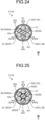
- FIG. 24 is a cross-sectional view illustrating an example of the configuration of the leakage portion 11.
- the dummy fiber 52 is entirely made of the metal member, whereas in the example of FIG. 24 , the dummy fiber 52 includes a core member 52a having an elastic modulus smaller than that of a metal material such as a synthetic resin material, and a cover 52b made of a metal material covering the surface of the core member.
- the shielding member 50 and thus the leakage portion 11 can be configured more flexibly.
- the cover 52b is an example of the metal member.
- the dummy fiber 52 may be the reflective member that reflects leakage light from the optical fiber 30.
- the dummy fiber 52 may be the dummy fiber 52 without the core member 52a and the cover 52b as in the example of FIG. 23 .
- FIG. 26 is a cross-sectional view illustrating an example of the configuration of the leakage portion 11.
- the leakage portion 11 has a configuration similar to that of the example of FIG. 23 .
- the number of optical fibers 30 is six, which is greater than that of the example of FIG. 23 .
- the shielding member 50 includes a dummy fiber 52C located at the center of the cross section and the dummy fibers 52 alternately arranged on the outer periphery of the dummy fiber 52C together with the optical fibers 30.
- the dummy fiber 52C located at the center of the cross section can function as a support member of the plurality of optical fibers 30 and the dummy fibers 52 arranged on the outer periphery of the dummy fiber 52C or a guide at the time of manufacturing. Since the diameter of the dummy fiber 52C is larger than the diameter of the optical fibers 30, leakage light from each optical fiber 30 toward the direction opposite to the radial directions D1 to D6 can be more reliably blocked.
- Protrusions 54 are provided on both sides of the recess 54a. Each of the protrusions 54 is located between the two optical fibers 30 in the circumferential direction of the irradiation probe 10. The protrusion 54 is an example of the intervening portion. The plurality of protrusions 54 is connected to each other and integrated on or near the central axis Ax1, that is, radially inward of the irradiation probe 10. Therefore, also in the example of FIG. 27 , functions and effects similar to those of FIGS. 15 and 16 can be obtained.
- the recess 54a and the optical fiber 30 may be in surface contact with each other, and a protrusion or a recess along the shape of the recess 54a may be formed on the outer surface 30a of the optical fiber 30 by providing a recess or a protrusion (not illustrated) in the recess 54a.
- the scattering region 33 in contact with the recess 54a can be formed on the outer surface 30a.
- the shielding member 50 is an example of the core wire, and the recess and the protrusion provided in the recess 54a are an example of a scattering body.
- FIG. 28 is a cross-sectional view of one optical fiber 30 in the leakage portion 11.
- the shielding member 50 partially covers the periphery of the optical fiber 30 in the leakage portion 11 and is configured as a sleeve 55 extending in the longitudinal direction.
- the sleeve 55 is provided with a slit-shaped opening 50a that is opened in the radial direction D1 and extends in the longitudinal direction. Also with such a configuration, the sleeve 55 is located between the two optical fibers 30 in the circumferential direction and is located radially inward of the irradiation probe 10 with respect to the optical fiber 30.
- the sleeve 55 can prevent leakage light from the optical fiber 30 from traveling in the direction opposite to the radial direction D1 and the circumferential direction of the irradiation probe 10. Further, the sleeve 55 may be the reflective member that reflects leakage light from the optical fiber 30.
- FIGS. 29 and 30 are side views of a modification of the end portion 10b of the irradiation probe 10 having a plurality of (three in this example) dummy fibers 52 as in the example of FIGS. 23 to 25 .
- FIGS. 29 and 30 are different from each other in rotational posture around the central axis Ax1 of the irradiation probe 10.
- the dummy fiber 52 includes a metal member, and in a case where projection light such as X-rays is emitted from the side along the radial direction, a projection image Im as indicated by a two-dot-dash line in FIGS. 29 and 30 can be obtained.
- positions and shapes in the longitudinal direction of end portions 52-1 to 52-3 of the dummy fiber 52 are set so that the rotational posture around the central axis Ax1 of the irradiation probe 10 can be determined from the projection image Im.
- the end portions 52-1 to 52-3 of the dummy fibers 52 are examples of a projected portion.
- the projected portion has at least two portions that are separated from each other in the longitudinal direction of the irradiation probe 10 and are separated from each other in the circumferential direction of the irradiation probe 10 at a central angle different from 0° or 180° when viewed in the longitudinal direction
- the projected shape of the projected portion changes according to the rotational posture.
- the central angle is 0° and 180°, for both of the two portions, there is a possibility of a rotational posture in which the width of the projected shape is too narrow to obtain a projected shape, and thus, the two portions are excluded.
- the end portions 52-1 to 52-3 of the three dummy fibers 52 are separated from each other in the X direction (longitudinal direction). As illustrated in FIGS. 23 to 25 , the three dummy fibers 52 are separated from the central axis Ax1 in the radial direction, and are separated from each other in the circumferential direction at a central angle of 120° therebetween when viewed in the longitudinal direction. Therefore, in the examples of FIGS. 29 and 30 , two end portions of the end portions 52-1 to 52-3 are examples of the two portions that exhibit functions and effects of determining the rotational posture by side projection. In this example, projection images Im different according to the rotational posture are obtained, including the rotational postures different from those in FIGS. 29 and 30 . Therefore, according to the examples of FIGS. 29 and 30 , it is possible to detect the rotational posture of the irradiation probe 10 relatively easily and accurately using the dummy fibers 52.
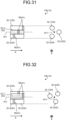
- the arrangement of the plurality of covers 56 is set so that the rotational posture around the central axis Ax1 of the irradiation probe 10 can be determined from the projection image Im in a case where the projection light is emitted from the side along the radial direction.
- the cover 56 is an example of the projected portion.
- the cover 56 may also be referred to as a marker.
- the covers 56 provided in the end portions 52-1 to 52-3 of the three dummy fibers 52 are separated from each other in the X direction (longitudinal direction).
- the covers 56 provided in the three dummy fibers 52 are separated from the central axis Ax1 in the radial direction, and, as illustrated on the right side of FIGS. 31 and 32 , are separated from each other in the circumferential direction at a central angle of 120° therebetween when viewed in the longitudinal direction. Therefore, in the examples of FIGS. 31 and 32 , two covers of the three covers 56 are examples of the two portions that exhibit functions and effects of determining the rotational posture by side projection.
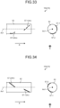
- FIGS. 33 and 34 are side views (left side) and front views (right side) of a modification of the end portion 10b of the irradiation probe 10 having a dummy fiber 52 passing through the central axis Ax1 as in the examples of FIGS. 23 to 26 .
- FIGS. 33 and 34 are different from each other in rotational posture around the central axis Ax1 of the irradiation probe 10.
- markers 57-1 and 57-2 made of a metal member or the like are provided on the outer periphery of the dummy fiber 52.
- the dummy fiber 52 is transparent to projection light such as X-rays, and the markers 57-1 and 57-2 are opaque to the projection light.
- the projection image Im can be obtained for the plurality of markers 57-1 and 57-2.
- the arrangement of the plurality of markers 57-1 and 57-2 is set so that the rotational posture around the central axis Ax1 of the irradiation probe 10 can be determined from the projection image Im in a case where the projection light is emitted from the side along the radial direction.
- the markers 57-1 and 57-2 are examples of the projected portion.
- the two portions and the projected portion can be implemented in various forms.
- the two portions and the projected portion can be provided on the shielding member 50 such as the plate 51 other than the dummy fiber 52, the optical fiber 30, the cover 13, or the like, and the shapes, arrangements, and the like of the two portions and the projected portion can be variously set.
- the present invention can be used in an irradiation probe and an irradiation probe system.
Landscapes
- Health & Medical Sciences (AREA)
- Life Sciences & Earth Sciences (AREA)
- Engineering & Computer Science (AREA)
- Biomedical Technology (AREA)
- Physics & Mathematics (AREA)
- General Health & Medical Sciences (AREA)
- Pathology (AREA)
- Nuclear Medicine, Radiotherapy & Molecular Imaging (AREA)
- Animal Behavior & Ethology (AREA)
- Public Health (AREA)
- Veterinary Medicine (AREA)
- Optics & Photonics (AREA)
- Surgery (AREA)
- Radiology & Medical Imaging (AREA)
- Chemical & Material Sciences (AREA)
- Analytical Chemistry (AREA)
- Biochemistry (AREA)
- General Physics & Mathematics (AREA)
- Immunology (AREA)
- Electromagnetism (AREA)
- Otolaryngology (AREA)
- Heart & Thoracic Surgery (AREA)
- Medical Informatics (AREA)
- Molecular Biology (AREA)
- Radiation-Therapy Devices (AREA)
Abstract
Description
- The present invention relates to an irradiation probe and an irradiation probe system.
- Conventionally, known examples of a medical probe that can be used for photodynamic therapy (PDT) or photodynamic diagnosis (PDD) include a probe that emits laser light from a side surface of the probe to the surrounding area and a probe that emits laser light from a side surface to a specific direction (for example, see Patent Literature 1).
- Patent Literature 1:
JP 3675482 B2 - In the case of using the probe that emits light entirely to the surrounding area from the side surface disclosed in
Patent Literature 1, the light may be unnecessarily applied to, for example, even a region in the living body where the light is not required to be applied originally or is not to be applied. - Further, in the case of using the probe that emits light only in a specific direction from the side surface disclosed in
Patent Literature 1, if the light is applied to, for example, a region in the living body different from a region originally intended to be irradiated, it is necessary to change the rotational posture around the axis of the probe. This change in rotational posture of the probe is not easy and is labor-intensive. - Therefore, one of the problems to be solved by the present invention is to achieve an improved novel irradiation probe and irradiation probe system that are, for example, capable of switching the irradiation direction of light from a side surface of the probe around the axis of the probe.
- An irradiation probe according to the present invention, for example, includes: a plurality of optical fibers bundled together, each of the optical fibers including, as at least a partial section in a longitudinal direction, a leakage section configured to output leakage light radially outward, wherein each of the optical fibers has directivity in which intensity of leakage light in a specific radial direction is higher than intensity of leakage light in another radial direction in a cross section intersecting an axial direction of the leakage section, the optical fibers are disposed apart from a central axis of the irradiation probe in radial directions different from each other, and the optical fibers are bundled together in a posture in which leakage light to the specific radial direction from the leakage section is directed radially outward of the irradiation probe.
- An irradiation probe according to the present invention, for example, includes: a plurality of optical fibers bundled together, each of the optical fibers including, as at least a partial section in a longitudinal direction, a leakage section configured to output leakage light radially outward, wherein the irradiation probe includes a reflective member placed at least radially inward of the irradiation probe with respect to the optical fiber and configured to reflect the leakage light from the optical fiber, each of the optical fibers has directivity in which intensity of leakage light in a specific radial direction is higher than intensity of leakage light in another radial direction in a cross section intersecting an axial direction of the leakage section, the optical fibers are disposed apart from a central axis of the irradiation probe in radial directions different from each other, and the optical fibers are bundled together in a posture in which leakage light to the specific radial direction from the leakage section is directed radially inward of the irradiation probe.
- In the irradiation probe, in the leakage section, at least one of the optical fibers may include a scattering region in which light is scattered in a predetermined range in a circumferential direction of the optical fiber.
- An outer surface of the optical fiber in the scattering region may be a convex curved surface in which an average radius of curvature in the scattering region is equal to or greater than a radius of a general region different from the scattering region, a plane intersecting a radial direction of the optical fiber, or a concave curved surface that is concave radially inward.
- The optical fibers may be disposed apart from a central axis of the irradiation probe in radial directions different from each other, and the irradiation probe may include a shielding member that prevents the leakage light from the leakage section of each of the optical fibers from traveling radially inward or a circumferential direction of the irradiation probe.
- An irradiation probe according to the present invention, for example, includes: a plurality of optical fibers bundled together, each of the optical fibers including, as at least a partial section in a longitudinal direction, a leakage section configured to output leakage light radially outward, wherein the optical fibers are disposed apart from a central axis of the irradiation probe in radial directions different from each other, and the irradiation probe includes a shielding member configured to prevent the leakage light from the leakage section of each of the optical fibers from traveling radially inward or a circumferential direction of the irradiation probe.
- In the irradiation probe, the shielding member may be configured to reflect the leakage light.
- In the irradiation probe, the shielding member may include an intervening portion placed between two optical fibers of the plurality of optical fibers in a circumferential direction of the irradiation probe.
- In the irradiation probe, the shielding member may include an opaque fiber that does not transmit leakage light.
- In the irradiation probe, the shielding member may include, as the opaque fiber, a first opaque fiber placed radially inward of the irradiation probe with respect to the optical fiber or placed between two optical fibers of the plurality of optical fibers in a circumferential direction of the irradiation probe.
- In the irradiation probe, the shielding member may include, as the opaque fiber: two first opaque fibers adjacent to each other; and a second opaque fiber placed on a side close to the optical fiber with respect to a boundary between the two first opaque fibers.
- In the irradiation probe, the shielding member may include a metal member.
- In the irradiation probe, the metal member may have conductivity.
- In the irradiation probe, the shielding member may include: a cover as the metal member; and a core member surrounded by the cover and made of a material having an elastic modulus smaller than an elastic modulus of the metal member.
- In the irradiation probe, the shielding member may include an extending portion extending in a radial direction of the irradiation probe at least in the leakage section.
- In the irradiation probe, a plurality of extending portions may be integrated radially inward of the irradiation probe as the extending portion.
- In the irradiation probe, the shielding member may include a sleeve configured to partially cover an outer periphery of the optical fiber at least in the leakage section and, extend in the longitudinal direction, the sleeve including an opening opened radially outward of the irradiation probe.
- In the irradiation probe, the irradiation probe may include a projected portion projected by projection light of the irradiation probe, the projected portion being configured such that, when the projection light is projected in a radial direction of the irradiation probe, a projected shape by the projection light varies depending on a rotational posture around a central axis of the irradiation probe.
- In the irradiation probe, the projected portion may include at least two portions that are separated from each other in the longitudinal direction and are separated from each other in a circumferential direction of the irradiation probe at a central angle different from 0° or 180° when viewed in the longitudinal direction.
- In the irradiation probe, the optical fiber may include an outer scattering portion placed radially outward of the irradiation probe in the leakage section to scatter light.
- In the irradiation probe, the optical fiber may include an inner scattering portion placed radially inward of the irradiation probe in the leakage section to scatter light.
- The irradiation probe may include a core wire extending in a longitudinal direction of the irradiation probe, wherein the plurality of optical fibers may be arranged along an outer periphery of the core wire.
- In the irradiation probe, a diameter of the core wire may be larger than a diameter of the optical fiber.
- In the irradiation probe, the plurality of optical fibers may be at least partially accommodated in a recess provided in the core wire.
- In the irradiation probe, the core wire may include a portion made of a synthetic resin material.
- In the irradiation probe, the core wire may include a scattering body.
- An irradiation probe system according to the present invention, for example, include: the irradiation probe; a light source; and a switching mechanism configured to selectively input light from the light source to at least one of the plurality of optical fibers.
- An irradiation probe system according to the present invention, for example, include: an irradiation probe including a plurality of optical fibers bundled together, the plurality of optical fibers being arranged side by side in a circumferential direction of the irradiation probe and configured to leak light radially outward from an outer surface of each of the plurality of optical fibers in a leakage section in a longitudinal direction; a light source; and a switching mechanism configured to selectively input light from the light source to at least one of the plurality of optical fibers.
- The irradiation probe system may include a plurality of light sources as the light source.
- The irradiation probe system may include a control mechanism configured to control at least one of the light source and the switching mechanism so that light from the light source is intermittently input to the optical fiber.
- In the irradiation probe system, the switching mechanism may be configured to operate so that the optical fiber to which light from the light source is input is sequentially switched over time in a circumferential direction of the irradiation probe.
- According to the present invention, for example, an improved novel irradiation probe system and irradiation probe can be achieved.
-
-
FIG. 1 is an exemplary and schematic configuration diagram of an irradiation probe system according to a first embodiment. -
FIG. 2 is an exemplary and schematic cross-sectional view of an irradiation probe according to the first embodiment. -
FIG. 3 is an exemplary and schematic cross-sectional view of a part of an optical fiber of the irradiation probe according to the first embodiment. -
FIG. 4 is an exemplary block diagram of an irradiation probe system according to an embodiment. -
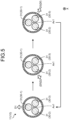
FIG. 5 is an exemplary and schematic cross-sectional view of an irradiation probe illustrating an example of a temporal change in a light irradiation state by the irradiation probe system of the embodiment. -
FIG. 6 is an exemplary and schematic cross-sectional view of an irradiation probe illustrating an example of a temporal change in a light irradiation state by the irradiation probe system of the embodiment. -
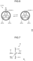
FIG. 7 is an exemplary schematic diagram of a switching mechanism of an irradiation probe system according to a second embodiment. -
FIG. 8 is an exemplary schematic diagram of the switching mechanism of the irradiation probe system according to the second embodiment, and is a diagram illustrating a state different from that inFIG. 7 . -
FIG. 9 is an exemplary schematic diagram of the switching mechanism of the irradiation probe system according to the second embodiment, and is a diagram illustrating a state different from those inFIGS. 7 and8 . -
FIG. 10 is a schematic cross-sectional view of a modification of a scattering region of an irradiation probe of the embodiment. -
FIG. 11 is a schematic cross-sectional view of a modification of the scattering region of the irradiation probe of the embodiment. -
FIG. 12 is a schematic cross-sectional view of a modification of the scattering region of the irradiation probe of the embodiment. -
FIG. 13 is a schematic side view of a modification of the scattering region of the irradiation probe of the embodiment. -
FIG. 14 is a schematic cross-sectional view of a modification of the scattering region of the irradiation probe of the embodiment. -
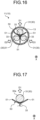
FIG. 15 is an exemplary and schematic cross-sectional view of an irradiation probe of a modification to the embodiment. -
FIG. 16 is an exemplary and schematic cross-sectional view of an irradiation probe of a modification to the embodiment. -
FIG. 17 is a partially enlarged view ofFIG. 16 . -
FIG. 18 is an exemplary and schematic cross-sectional view of a part of an irradiation probe of a modification to the embodiment. -
FIG. 19 is an exemplary and schematic cross-sectional view of a part of an irradiation probe of a modification to the embodiment. -
FIG. 20 is an exemplary and schematic cross-sectional view of a part of an irradiation probe of a modification to the embodiment. -
FIG. 21 is an exemplary and schematic cross-sectional view of a part of an irradiation probe of a modification to the embodiment. -
FIG. 22 is an exemplary and schematic cross-sectional view of a part of an irradiation probe of a modification to the embodiment. -
FIG. 23 is an exemplary and schematic cross-sectional view of an irradiation probe of a modification to the embodiment. -
FIG. 24 is an exemplary and schematic cross-sectional view of an irradiation probe of a modification to the embodiment. -
FIG. 25 is an exemplary and schematic cross-sectional view of an irradiation probe of a modification to the embodiment. -
FIG. 26 is an exemplary and schematic cross-sectional view of an irradiation probe of a modification to the embodiment. -
FIG. 27 is an exemplary and schematic cross-sectional view of an irradiation probe of a modification to the embodiment. -
FIG. 28 is an exemplary and schematic cross-sectional view of a part of an optical fiber of a modification to the embodiment. -
FIG. 29 is an exemplary and schematic side view of a shielding member provided in an end portion of an irradiation probe of a modification to the embodiment. -
FIG. 30 is an exemplary and schematic side view of the shielding member ofFIG. 29 in which a rotational posture around a central axis is different from that ofFIG. 29 . -
FIG. 31 is an exemplary and schematic diagram illustrating a shielding member provided in an end portion of an irradiation probe of a modification to the embodiment. -
FIG. 32 is an exemplary and schematic diagram illustrating the shielding member ofFIG. 31 in which a rotational posture around a central axis is different from that ofFIG. 31 . -
FIG. 33 is an exemplary and schematic diagram illustrating a shielding member provided in an end portion of an irradiation probe of a modification to the embodiment. -
FIG. 34 is an exemplary and schematic diagram illustrating the shielding member ofFIG. 33 in which a rotational posture around a central axis is different. Description of Embodiments - Hereinafter, exemplary embodiments of the present invention and modifications thereto are disclosed. Configurations of the embodiments and the modifications described below, and functions and results (effects) provided by the configurations thereof are examples. The present invention can also be realized by configurations other than those disclosed in the following embodiments and modifications. In addition, according to the present invention, it is possible to obtain at least one of various effects (including derivative effects also) achieved by the configuration.
- The plurality of embodiments and modifications described below have similar configurations. Therefore, according to the configurations of the embodiments and modifications, similar functions and effects based on the similar configurations can be obtained. In addition, in the following description, the similar configurations are given similar symbols, and duplicate descriptions may be omitted.
- In the present specification, ordinal numbers are given for convenience in order to distinguish components, parts, directions, and the like, and do not indicate priority or order.
- In the drawings, the X direction is an axial direction (longitudinal direction) of an
irradiation probe 10. -
FIG. 1 is a schematic diagram of anirradiation probe system 1 according to an embodiment. As illustrated inFIG. 1 , theirradiation probe system 1 includes alight output device 100, theirradiation probe 10, acontrol device 200, a deliveryoptical fiber 20, and aninput unit 220. - The
light output device 100 includes a plurality oflight source units 110. Each of thelight source units 110 includes a light source that outputs laser light and an optical system that guides light from the light source to the delivery optical fiber 20 (both are not illustrated). The light source includes, for example, a laser device that outputs laser light. Further, in the embodiment, thelight output device 100 includes the plurality oflight source units 110, that is, the light sources as an example, but thelight output device 100 is not limited thereto. It is only required that thelight output device 100 includes at least onelight source unit 110. - Each of the
light source units 110 and theirradiation probe 10 are optically connected via the deliveryoptical fiber 20 provided to correspond to the subjectlight source unit 110. - The
irradiation probe 10 includes a plurality of optical fibers, has an elongated substantially cylindrical and linear shape, and has flexibility. Theirradiation probe 10 has anend portion 10a that is one end in the axial direction and anend portion 10b that is the other end in the axial direction. Theend portion 10a is an input end to which light from thelight source units 110 is input, and may also be referred to as a base end. Theend portion 10b is positioned on the side opposite to theend portion 10a in the axial direction, and may also be referred to as a distal end. - The
irradiation probe 10 includes aleakage portion 11 and atransmission portion 12. Theleakage portion 11 is provided over a predetermined length in the axial direction at a position away from theend portion 10a, and is a section that leaks light radially outward from anouter surface 10c of theirradiation probe 10. Light leaking from theouter surface 10c as a side surface of theleakage portion 11 is irradiation light from theirradiation probe 10. In addition, thetransmission portion 12 is a section that transmits light between theend portion 10a and theleakage portion 11, between theleakage portion 11 and theend portion 10b, or, in a case where the plurality ofleakage portions 11 is axially provided at an interval, thetransmission portion 12 is a section that transmits light between the twoleakage portions 11 sandwiching the interval. In the embodiment, as an example, theleakage portion 11 is provided only in the section adjacent to theend portion 10b, but the present invention is not limited thereto, and theleakage portion 11 may be provided apart from theend portion 10b. - The
control device 200 can control thelight source units 110 to output light or stop the output, for example. Further, thecontrol device 200 can control operations of devices and portions other than thelight source units 110 in theirradiation probe system 1. Theinput unit 220 constitutes a user interface operated by an operator (user), and inputs an instruction signal to thecontrol device 200 in response to an operation input of the operator. Thecontrol device 200 is an example of a control mechanism, and theinput unit 220 is an example of an operation input unit. -
FIG. 2 is a cross-sectional view of theleakage portion 11 of theirradiation probe 10. As illustrated inFIG. 2 , theirradiation probe 10 includes a plurality ofoptical fibers 30 bundled together and acover 13 transparent to light transmitted through theoptical fibers 30. In the embodiment, as an example, theirradiation probe 10 includes the threeoptical fibers 30, but the number ofoptical fibers 30 is not limited to three, and may be two or four or more. - The plurality of
optical fibers 30 is arranged at substantially equal intervals and in a substantially rotationally symmetric manner around a central axis Ax1 of theirradiation probe 10. In other words, theoptical fibers 30 are placed to be shifted from the central axis Ax1 of theirradiation probe 10 in different radial directions D1 to D3. Note that theirradiation probe 10 may include a holding member (not illustrated) that holds the plurality ofoptical fibers 30 in a predetermined relative positional relationship in a cross section intersecting the axial direction of theleakage portion 11. - The
optical fibers 30 are optically connected to the deliveryoptical fibers 20, respectively. Theoptical fiber 30 and the deliveryoptical fiber 20 may be directly connected by fusion or the like, or indirectly connected via a coupling portion or the like, or theoptical fiber 30 and the deliveryoptical fiber 20 may be made of a single optical fiber. - Each of the
optical fibers 30 includes acore 31 and a clad (not illustrated) surrounding thecore 31. In thetransmission portion 12, theoptical fiber 30 includes thecore 31 and the clad. On the other hand, in theleakage portion 11, for example, as illustrated inFIG. 2 , the clad is substantially removed from eachoptical fiber 30, and only thecores 31 are bundled together. That is, in the example ofFIG. 2 , anouter surface 30a of eachoptical fiber 30 is an outer surface of thecore 31. - In the
leakage portion 11, ascattering region 33 in which light is scattered is provided in at least one of theouter surface 30a and a range having a predetermined depth in the vicinity of theouter surface 30a. Thescattering region 33 extends in the circumferential direction. Specifically, as illustrated inFIG. 2 , thescattering region 33 is provided in a partial section in the circumferential direction, specifically, in a fan-shaped arc having a predetermined central angle (InFIG. 2 , as an example, 60 deg.) or in a range near the fan-shaped arc, in a cross section orthogonal to a central axis Ax2 of theoptical fiber 30. Although not illustrated, thescattering region 33 extends also in the axial direction (longitudinal direction). In other words, thescattering region 33 is provided over a predetermined section in the longitudinal direction of theleakage portion 11. Thescattering region 33 may be provided over the entire region of theleakage portion 11, may be provided over a part of the region of theleakage portion 11, or may be intermittently provided at a plurality of positions of theleakage portion 11. In a case where a plurality of scatteringregions 33 is provided in theleakage portion 11, thescattering regions 33 are provided side by side in the longitudinal direction. In theoptical fiber 30, the section in which thescattering region 33 is provided is an example of a leakage section. The leakage section is included in theleakage portion 11. In other words, the leakage section of theoptical fiber 30 in which thescattering region 33 is provided is a part of the constituent elements of theleakage portion 11 of theirradiation probe 10. -
FIG. 3 is a cross-sectional view of theoptical fiber 30 at a portion where thescattering region 33 is provided. As illustrated inFIG. 3 , in thescattering region 33, a plurality ofrecesses 33a is formed on theouter surface 30a. Light transmitted in thecore 31 is refracted and scattered in therecesses 33a, and leaks from theouter surface 30a to the outside of the core 31, that is, the outside of theoptical fiber 30. - In the example of
FIG. 3 , therecesses 33a are discretely formed, and the size and depth of therecesses 33a are not constant. However, this is an example, and the plurality ofrecesses 33a may be regularly arranged, or specifications of the plurality ofrecesses 33a, e.g., a size, a depth, and a shape may be substantially constant. In thescattering region 33, instead of therecess 33a, a protrusion may be formed on theouter surface 30a. The protrusion may be, for example, a portion between therecess 33a and therecess 33a. In the embodiment, leakage of light radially outward from thecore 31 is facilitated due to therecesses 33a and the protrusions. The specifications of therecesses 33a and the protrusions, e.g., locations, densities, the size, and the depth thereof, are appropriately adjusted, so that the distribution of the intensity of light leakage in the axial direction and the circumferential direction of theleakage portion 11 can be appropriately adjusted. - The
scattering region 33 is appropriately provided in theoptical fiber 30. As a result, theoptical fiber 30 can be configured as an optical fiber in which the intensity of leakage light to a specific radial direction (radially outward) from the central axis Ax2 of theoptical fiber 30 is higher than the intensity of leakage light to the other radial directions in the intensity distribution in the circumferential direction of the leakage light in the cross section intersecting the axial direction, that is, theoptical fiber 30 can be configured as an optical fiber having directivity. In the example ofFIG. 2 , in eachoptical fiber 30, the intensity of the leakage light to a radial direction Df is higher than the intensity thereof in the other radial directions. The radial direction Df is an example of the specific radial direction. In the present specification, the specific radial direction is a radial direction where the peak is reached in the intensity distribution in the circumferential direction of theoptical fiber 30 of the leakage light from theoptical fiber 30. In a case where there is a plurality of radial directions (for example, two directions) where the peak is reached, each direction is the specific radial direction. - Here, as described above, in the embodiment, the
optical fibers 30 having the above-described directivity of the leakage light are disposed apart from the central axis Ax1 of theirradiation probe 10 in the radial directions D1 to D3 different from each other. Theoptical fibers 30 are bundled together in a posture in which the leakage light to the radial direction Df from thescattering region 33 is directed radially outward of theirradiation probe 10 in theleakage portion 11. In the embodiment, as an example, as illustrated inFIG. 2 , each of theoptical fibers 30 is arranged in a posture in which thescattering region 33 is located farthest from the central axis Ax1 of theirradiation probe 10, so that leakage light output to the radial direction Df from theoptical fibers 30 is output toward the radial directions D1 to D3 (radially outward) different from each other in theirradiation probe 10. - The
light source units 110 are optically connected to theoptical fibers 30 different from each other. Therefore, thecontrol device 200 controls thelight output device 100 so that any one of the plurality oflight source units 110 selectively outputs light, to thereby select, from among the plurality ofoptical fibers 30, theoptical fiber 30 that outputs leakage light. Here, as described above, leakage light is output from theleakage portion 11 of theirradiation probe 10 to the radial directions D1 to D3 different from each other according to theoptical fibers 30. Therefore, thecontrol device 200 selectively operates thelight source units 110 to thereby switch the output direction of leakage light from theleakage portion 11, that is, irradiation light output from theirradiation probe 10, namely, the radial directions D1 to D3. Thecontrol device 200 is an example of a switching mechanism. -
FIG. 4 is a block diagram of theirradiation probe system 1. As illustrated inFIG. 4 , theirradiation probe system 1 includes thecontrol device 200, theinput unit 220, and anoutput unit 230. Theinput unit 220 and theoutput unit 230 construct a user interface for the user and the operator. Theinput unit 220 is, for example, an input device such as an operation unit, e.g., a remote controller, a switch box, or a joystick, or an input device, e.g., a keyboard, a touch panel, a mouse, a switch, or an operation button. Theoutput unit 230 is, for example, a display, a printer, a lamp, a speaker, or the like, and is an output device using image, printing, or audio. - The
control device 200 includes acontroller 210, amain storage unit 241, and anauxiliary storage device 242. - The
controller 210 is, for example, a processor (circuit) such as a central processing unit (CPU). Themain storage unit 241 is, for example, a random access memory (RAM) or a read only memory (ROM). Theauxiliary storage device 242 is a nonvolatile rewritable storage device such as a solid state drive (SSD) or a hard disk drive (HDD). - The
controller 210 operates as anirradiation control unit 211, aninput control unit 212, and anoutput control unit 213 by reading programs stored in themain storage unit 241 and theauxiliary storage device 242 to execute each processing. Each of the programs may be provided by being recorded on a computer-readable recording medium in an installable or executable format file. The recording medium may also be referred to as a program product. Information such as values, maps, and tables used in arithmetic processing by the programs and the processor may be stored in advance in themain storage unit 241 or theauxiliary storage device 242, or may be stored in a storage unit of a computer connected to a communication network and stored in theauxiliary storage device 242 by being downloaded via the communication network. Theauxiliary storage device 242 stores data written by the processor. Further, the arithmetic processing by thecontroller 210 may be executed at least partially by hardware. In this case, thecontroller 210 may include, for example, a field programmable gate array (FPGA), an application specific integrated circuit (ASIC), or the like. - The
irradiation control unit 211 can control each of thelight source units 110 included in thelight output device 100 to output light and stop outputting the light. Further, theirradiation control unit 211 can switch thelight source unit 110 that outputs light, among the plurality of light source units 110 (light sources), in response to the operator inputting operation to theinput unit 220. In other words, theirradiation control unit 211 operates to switch the irradiation directions (radial directions D1 to D3) of light from theirradiation probe 10. - The
input control unit 212 receives an input signal from theinput unit 220. Further, theinput control unit 212 may control theinput unit 220 to enable predetermined operation input. - The
output control unit 213 controls theoutput unit 230 to execute predetermined output. -
FIGS. 5 and6 are cross-sectional views of theleakage portion 11 illustrating an example of a temporal change in a light irradiation state by theirradiation probe 10. - In the example of
FIG. 5 , theirradiation control unit 211 sequentially switches between the operation state and the operation stop state of the threelight source units 110, so that a state in which light is input from thelight output device 100 to the optical fiber 30-1, a state in which light is input from thelight output device 100 to the optical fiber 30-2, and a state in which light is input from thelight output device 100 to the optical fiber 30-3 are sequentially and repeatedly switched. Thereby, a state in which the irradiation light as the leakage light is output from theleakage portion 11 in the radial direction D1 (upward inFIG. 5 ), a state in which the irradiation light as the leakage light is output in the radial direction D2 (lower left inFIG. 5 ), and a state in which the irradiation light as the leakage light is output in the radial direction D3 (lower right inFIG. 5 ) are sequentially and repeatedly switched. In this case, the irradiation light from theirradiation probe 10 rotates around the central axis Ax1 of theirradiation probe 10. - In the example of
FIG. 6 , theirradiation control unit 211 switches between the operation state and the operation stop state of onelight source unit 110, so that a state in which light is input from thelight output device 100 to the optical fiber 30-1 and a state in which light is not input to any of theoptical fibers 30 are alternately switched. As a result, the irradiation light as the leakage light is intermittently output in the radial direction D1 (upward inFIG. 6 ). In other words, the irradiation light output in the radial direction D1 flashes at predetermined time intervals. - The intensity of light irradiation can be reduced and the damage to the living tissue due to the light and heat can be reduced by the rotation of irradiation light as illustrated in
FIG. 5 or the flash of irradiation light as illustrated inFIG. 6 . The rotation direction, the rotation speed, the flash speed, changes thereof, and the like are not limited to the examples ofFIGS. 5 and6 , and can be appropriately set. - As described above, in the embodiment, the
control device 200 operates, so that the irradiation direction of light (leakage light and irradiation light) from theirradiation probe 10 can be switched without changing the rotational posture around the central axis Ax1 of theirradiation probe 10. Therefore, for example, in a case where the irradiation direction is changed because light is applied, from theirradiation probe 10, to a region different from a region originally intended to be irradiated with light, or because light is to be applied in different radial directions, changing the rotational posture of theirradiation probe 10 is unnecessary or minimized, so that the irradiation direction can be changed more easily or more quickly. - Further, in the embodiment, the
control device 200 operates to rotate light around the central axis Ax1 of theirradiation probe 10 or flash light, so that the irradiation intensity, the irradiation area, and the irradiation timing of the light are adjusted, and a more appropriate light irradiation state for the affected area can be easily achieved. -
FIGS. 7 to 9 are schematic diagrams of aswitching mechanism 40 included in theirradiation probe system 1 according to the second embodiment.FIG. 7 illustrates a state in which light from thelight output device 100 is input to the optical fiber 30-1,FIG. 8 illustrates a state in which light from thelight output device 100 is input to the optical fiber 30-2, andFIG. 9 illustrates a state in which light from thelight output device 100 is input to the optical fiber 30-3. In theirradiation probe system 1 of the embodiment, theswitching mechanism 40 can select theoptical fiber 30 that inputs light from the deliveryoptical fiber 20, that is, theoptical fiber 30 that leaks and outputs light in theleakage portion 11. - The
switching mechanism 40 includes, for example, amovable portion 40a movable in the Y direction inFIG. 7 to 9 , and themovable portion 40a includesmirrors 40b-1 and 40b-3 provided at different positions in the Y direction. Theswitching mechanism 40 also includes a drive mechanism (not illustrated) capable of changing the position of themovable portion 40a in the Y direction. The drive mechanism includes, for example, a motor, a speed reduction mechanism that decelerates rotation of the motor, and a motion conversion mechanism that converts rotation of the speed reduction mechanism into linear motion of themovable portion 40a along the Y direction. The operation of the switching mechanism 40 (drive mechanism) is controlled by a switchingcontrol unit 214 included in thecontroller 210 as illustrated inFIG. 4 . Note that the drive mechanism is not limited to have such a configuration, and may include another mechanism such as an electromagnetic solenoid. - In such a configuration, the
switching mechanism 40 changes the position of themovable portion 40a in the Y direction, so that theswitching mechanism 40 can switch a state in which light from thelight output device 100 is reflected by themirror 40b-1 and then coupled to the optical fiber 30-1 (FIG. 7 ), a state in which light from thelight output device 100 is coupled to the optical fiber 30-2 without passing through themirrors 40b-1 and 40b-3 (FIG. 8 ), and a state in which light from thelight output device 100 is reflected by themirror 40b-3 and then coupled to the optical fiber 30-3 (FIG. 9 ). - The configuration of the
irradiation probe 10 is similar to that of the first embodiment. Therefore, also in the embodiment, it is possible to selectively output light from any one of the plurality ofoptical fibers 30 in theleakage portion 11, and thus, it is possible to obtain the functions and effects similar to those of the first embodiment. - Then, according to the embodiment, it is not necessary to provide one
light source unit 110 for each of theoptical fibers 30, and accordingly, the number oflight source units 110 in thelight output device 100 can be further reduced. As a result, it is possible to obtain advantages that thelight output device 100 can be configured to be smaller or lighter and that the labor and cost involved in manufacturing thelight output device 100 can be reduced. -
FIGS. 10 and 11 are cross-sectional views each illustrating an example of a configuration of thescattering region 33. In the example ofFIG. 10 ,particles 33b are included inside theoptical fiber 30 in which thescattering region 33 is formed, and in the example ofFIG. 11 ,holes 33c are included inside theoptical fiber 30 in which thescattering region 33 is formed. Theparticles 33b and theholes 33c may have, for example, a nanostructure with a diameter of 100 [nm] or less. Theparticles 33b may be, for example, fillers such as fine particles or fine tubes. In these cases, the direction of light travel is changed due to theparticles 33b and theholes 33c, that is, light is scattered. Thus, light easily leaks radially outward from theouter surface 30a. -
FIG. 12 is a cross-sectional view illustrating another example of the configuration of thescattering region 33. In the example ofFIG. 12 , theouter surface 30a of theoptical fiber 30 is inclined to the X direction that is the longitudinal direction of theoptical fiber 30. Theouter surface 30a is, for example, a tapered surface or the like. As described above, in a part where the shape of theouter surface 30a changes as theouter surface 30a extends in the X direction, for example, light enters the part beyond the critical angle, so that the light easily leaks radially outward from theouter surface 30a. Theparticles 33b and theholes 33c may also be referred to as scattering elements. -
FIG. 13 is a side view illustrating another example of the configuration of thescattering region 33. In the example ofFIG. 13 , thescattering region 33 is curved. Light easily leaks from the curve part. That is, also with the configuration ofFIG. 13 , light easily leaks radially outward from theouter surface 30a. -
FIG. 14 is a cross-sectional view illustrating another example of the configuration of thescattering region 33. In the example ofFIG. 14 , thescattering region 33 includes acover layer 32 that at least partially covers anouter surface 31a of thecore 31. The refractive index of thecover layer 32 is set to be substantially the same as or higher than the refractive index of thecore 31. Further, thecover layer 32 includesscattering elements 33d such as particles or holes. In this case, light that has reached the interface between the core 31 and thecover layer 32 enters thecover layer 32, is scattered by thescattering element 33d, and leaks radially outward. According to such a configuration, for example, it is possible to obtain an advantage that the provision of thecover layer 32 enables appropriately setting or changing a place where light leaks, a place where light easily leaks, or a place where the intensity of leakage light becomes high. In addition, in a case where thecore 31 is appropriately pressurized radially inward by thecover layer 32, light easily leaks from the pressurized part. - The configurations illustrated in
FIGS. 10 to 14 may be appropriately combined in theoptical fiber 30 for implementation. -
FIG. 15 is a cross-sectional view illustrating an example of a configuration of theleakage portion 11. In the example ofFIG. 15 , theleakage portion 11 includes a shieldingmember 50. The shieldingmember 50 blocks leakage light from theoptical fibers 30 positioned to be shifted from the central axis Ax1 of theirradiation probe 10 in the radial directions D1 to D3 (hereinafter, referred to as eccentric directions) from being directed in the direction opposite to the eccentric direction and the circumferential direction of theirradiation probe 10. - The specifications of the
scattering region 33 are adjusted, so that leakage light having high directivity in the radial directions D1 to D3, which are eccentric directions of theoptical fibers 30, is output from eachoptical fiber 30. However, although the ratio is low, a part of the leakage light is output in a direction other than the radial directions D1 to D3, that is, in a direction different from the intended direction. Such light output in a direction different from the intended direction causes a decrease in directivity as theirradiation probe 10, and the light is unnecessarily applied to, for example, even a region in the living body where the light is not required to be applied originally or is not to be applied. In this regard, according to the modification ofFIG. 15 , the shieldingmember 50 can prevent leakage light (irradiation light) from theirradiation probe 10 from being output in a direction other than the intended directions (radial directions D1 to D3), and it is thus possible to prevent a decrease in directivity as theirradiation probe 10, and it is also possible to prevent the light from being unnecessarily applied to, for example, even a region in the living body where the light is not required to be applied originally or is not to be applied. - In the example of
FIG. 15 , the shieldingmember 50 includes a plurality ofplates 51. Each of theplates 51 extends in a radial direction from the central axis Ax1 so as to pass between the twooptical fibers 30. In other words, theplate 51 is positioned between the twooptical fibers 30 in the circumferential direction of theirradiation probe 10. The plurality ofplates 51 is connected to each other and integrated on or near the central axis Ax1, that is, radially inward of theirradiation probe 10. In such a configuration, for each of theoptical fibers 30, twoplates 51 are located in the opposite direction to the eccentric direction of the subjectoptical fiber 30, and are located on both sides in the circumferential direction of the subjectoptical fiber 30. Such a configuration prevents leakage light from theoptical fibers 30 from traveling in the opposite direction to the eccentric direction and the circumferential direction of theirradiation probe 10. Theplate 51 is an example of an intervening portion and an example of an extending portion. - The shielding
member 50 includes, for example, a metal member, and shields leakage light from theoptical fiber 30. The shieldingmember 50 may be entirely made of a metal material such as, for example, a copper-based material. This enhances heat dissipation in theleakage portion 11 and reduces the rise in temperature of theleakage portion 11. In this case, the shieldingmember 50 is an example of the metal member. Further, the shieldingmember 50 may include, for example, a core member having an elastic modulus smaller than that of a metal material such as a synthetic resin material, and a cover made of a metal material covering a surface of the core member. In this case, the shieldingmember 50 and thus theleakage portion 11 can be configured more flexibly. In this case, the cover is an example of the metal member. - The shielding
member 50 may reflect leakage light. The shieldingmember 50 reflects leakage light traveling in a direction different from the intended direction in a direction close to the intended direction, which improves the directivity as theirradiation probe 10. In this case, the shieldingmember 50 is an example of a reflective member. -
FIG. 16 is a cross-sectional view illustrating an example of the configuration of theleakage portion 11. In the example ofFIG. 15 , thescattering region 33 is located radially outward of theirradiation probe 10 in eachoptical fiber 30, whereas in the example ofFIG. 16 , thescattering region 33 is located radially inward of theirradiation probe 10 in eachoptical fiber 30. Thescattering region 33 in the case ofFIG. 15 is an example of an inner scattering portion, and thescattering region 33 in the case ofFIG. 16 is an example of an outer scattering portion. - In addition, each of the
optical fibers 30 has directivity in which the intensity of leakage light directed radially outward of theirradiation probe 10 and the intensity of leakage light directed radially inward of theirradiation probe 10 in the posture ofFIG. 16 are higher than the intensity of leakage light in the other directions, in the intensity distribution in the circumferential direction of theoptical fiber 30 of leakage light by adjusting the specifications of thescattering region 33. In other words, theoptical fibers 30 have radiation characteristics of leakage light having high directivity in two directions of the radial directions D1 to D3 (eccentric directions, radially outward) and a direction opposite to the eccentric directions (radially inward) in the posture of bundledoptical fibers 30 as illustrated inFIG. 16 . Further, the shieldingmember 50 is an example of the reflective member, and is configured to reflect leakage light. - In this case, for each
optical fiber 30, part of the light (scattered light) directed radially outward of theirradiation probe 10 in thescattering region 33 is totally reflected by a surface (hereinafter, referred to as a facing surface) on the opposite side of thescattering region 33 of theoptical fiber 30 and remains in theoptical fiber 30. Further, another part of the light directed radially outward of theirradiation probe 10 in thescattering region 33 does not satisfy total reflection conditions on the facing surface, and thus, leaks from the facing surface to outside of the subjectoptical fiber 30, and is directed in the radial directions D1 to D3 or a direction close to the radial directions D1 to D3. - On the other hand, part of the light (scattered light) directed radially inward of the
irradiation probe 10 in thescattering region 33 is reflected by the shieldingmember 50 and then directed in the radial directions D1 to D3 or a direction close to the radial directions D1 to D3. Further, another part of the scattered light directed radially inward of theirradiation probe 10 in thescattering region 33 enters theoptical fiber 30 again, and is divided, at the facing surface, into light remaining in theoptical fiber 30 and light to be output from the facing surface in the radial directions D1 to D3 or in a direction close to the radial directions D1 to D3. - With such a configuration, the
leakage portion 11 outputs leakage light having high directivity in the eccentric directions (radial directions D1 to D3) of theoptical fibers 30. - In this example, most of the scattered light from the
scattering region 33, including the light that is reflected by the shieldingmember 50 to enter again theoptical fiber 30, is output to the outside of theleakage portion 11 through the facing surface. On the facing surface, light that does not satisfy the total reflection conditions, that is, light having a small inclination angle with respect to the radial directions D1 to D3, selectively leaks to the outside of theoptical fiber 30. Therefore, according to the configuration in which thescattering region 33 is located radially inward of theirradiation probe 10 in eachoptical fiber 30 as in the examples ofFIGS. 16 and 17 , the directivity in the radial directions D1 to D3 as theirradiation probe 10 is increased as compared with the configuration in which thescattering region 33 is located radially inward of theirradiation probe 10 in eachoptical fiber 30. -
FIG. 17 is a partially enlarged view of a modification toFIG. 16 . In the example ofFIG. 17 , the average radius of curvature in thescattering region 33 is the same as a radius of a general region of theouter surface 30a of theoptical fiber 30 in which thescattering region 33 is not formed. In this case, in thescattering region 33, theouter surface 30a is a convex curved surface. -
FIG. 18 illustrates another modification in which the shape of thescattering region 33 is changed from the example ofFIG. 17 . In the example ofFIG. 18 , the average radius of curvature of theouter surface 30a in thescattering region 33 is equal to or greater than a radius of a general region of theouter surface 30a of theoptical fiber 30 in which thescattering region 33 is not formed. Also in this case, in thescattering region 33, theouter surface 30a is a convex curved surface. -
FIG. 19 illustrates another modification in which the shape of thescattering region 33 is changed from the example ofFIG. 17 . In the example ofFIG. 19 , theouter surface 30a in thescattering region 33 is a plane intersecting the radial direction of theoptical fiber 30. -
FIG. 20 illustrates another modification in which the shape of thescattering region 33 is changed from the example ofFIG. 17 . In the example ofFIG. 20 , theouter surface 30a in thescattering region 33 is a concave curved surface that is concave radially inward of theoptical fiber 30. - The inventors have intensively studied various modifications as illustrated in
FIGS. 17 to 20 , and found that a distribution ratio between scattered light (hereinafter, referred to as first scattered light) traveling from thescattering region 33 to radially inward of theirradiation probe 10, that is, traveling in a direction opposite to the eccentric direction of eachoptical fiber 30, and scattered light (hereinafter, referred to as second scattered light) traveling from thescattering region 33 to radially outward of theirradiation probe 10, that is, traveling in the eccentric direction (radial directions D1 to D3) of eachoptical fiber 30 can be adjusted according to the specifications of thescattering region 33. Hereinafter, the ratio of the second scattered light to the first scattered light is referred to as a branching ratio. - Specifically, it has been found that, in a case where the average radius of curvature of the
outer surface 30a in thescattering region 33 is greater than the radius of theouter surface 30a in the general region as illustrated inFIG. 18 , the branching ratio can be increased as compared with a case where the average radius of curvature of theouter surface 30a in thescattering region 33 is the same as the radius of the general region as illustrated inFIG. 17 . Further, it has been found that, in a case where theouter surface 30a in thescattering region 33 is a flat surface or a concave curved surface as illustrated inFIGS. 19 and20 , the branching ratio can be reduced as compared with a case where the radius of curvature of theouter surface 30a in thescattering region 33 is the same as the radius of the general region. Further, it has been found that the magnitude of the branching ratio can be adjusted by adjusting various specifications of thescattering region 33 such as the radius of curvature and the circumferential length of thescattering region 33. As a result, for example, an effect of increasing the degree of freedom of design as theirradiation probe 10 can be obtained. - In the examples of
FIGS. 17 to 20 , the scattering element in thescattering region 33 can be configured as therecess 33a (seeFIG. 3 ) or the protrusion formed on theouter surface 30a, theparticles 33b (seeFIG. 10 ) or theholes 33c (seeFIG. 11 ) provided inside and in the vicinity of theouter surface 30a, or the like. - Further, in forming the
recesses 33a or the protrusions in thescattering region 33, masking is performed on theouter surface 30a of theoptical fiber 30 except for a part where thescattering region 33 is to be formed, and processing of forming an uneven surface such as sandblasting is performed on an unmasked opening part, whereby therecesses 33a or the protrusions can be formed. In this case, the shape and the radius of curvature of thescattering region 33 can be appropriately adjusted by performing masking in multiple stages or adjusting the irradiation time according to the irradiation direction for sandblasting. -
FIG. 21 illustrates another modification in which the shape of thescattering region 33 is changed from the example ofFIG. 17 . InFIG. 21 , thescattering region 33 is formed as thecover layer 32 as illustrated inFIG. 14 . Thecover layer 32 can be configured as a part of a thin cladding layer. Also in such a configuration, functions and effects similar to those in the examples ofFIGS. 15 to 20 can be obtained. -
FIG. 22 is a cross-sectional view of a modification in which the directivity of the leakage light by theoptical fiber 30 is reduced as compared with the examples ofFIGS. 15 and16 . Instead of having thescattering region 33 only in a specific part in the circumferential direction, in the example ofFIG. 22 , theoptical fiber 30 has the scattering element substantially uniformly or entirely in the substantially entire region of the cross section or theouter surface 30a or the region close to theouter surface 30a. In this case, the intensity distribution of the leakage light in the circumferential direction of theoptical fiber 30 is a relatively flat distribution without a peak in a specific radial direction. However, also in this case, by configuring the shieldingmember 50 as a reflective member, leakage light (irradiation light) having relatively high directivity in the eccentric directions (radial directions D1 to D3) of theoptical fiber 30 is output from theirradiation probe 10 including the reflected light at the shieldingmember 50. - In the examples of
FIGS. 15 and16 , the plurality ofplates 51 may be separated from each other. In this case, the boundary between the plurality ofplates 51 may be covered with another shielding member (not illustrated). -
FIG. 23 is a cross-sectional view illustrating an example of the configuration of theleakage portion 11. In the example ofFIG. 23 , the shieldingmember 50 includes a plurality ofdummy fibers 52. The plurality ofdummy fibers 52 include thedummy fiber 52 located at the center of the cross section of theirradiation probe 10 and thedummy fiber 52 located between the twooptical fibers 30. Theoptical fibers 30 and thedummy fibers 52 are alternately arranged in the circumferential direction around thedummy fiber 52 located at the center of the cross section. - The
dummy fiber 52 includes, for example, a metal member, and shields leakage light from theoptical fiber 30. In addition, for eachoptical fiber 30, thedummy fibers 52 are placed radially inward of theirradiation probe 10 and on both sides of the subjectoptical fiber 30 in the circumferential direction. Therefore, according to the example ofFIG. 23 , the plurality ofdummy fibers 52 can function as the shieldingmembers 50. Thedummy fiber 52 is an example of an opaque fiber that does not transmit leakage light, and is an example of a first opaque fiber. - The
dummy fiber 52 may be made of, for example, a conductive metal material such as a copper-based material. In this case, thedummy fiber 52 can be used as a conductor for power or an electric signal. Further, in this case, thedummy fiber 52 may have an insulating cover. - In the example of
FIG. 23 , thedummy fiber 52 may be a reflective member that reflects leakage light from theoptical fiber 30. For example, thedummy fiber 52 may be made of a synthetic resin material having high reflectivity such as polytetrafluoroethylene (PTFE). -
FIG. 24 is a cross-sectional view illustrating an example of the configuration of theleakage portion 11. In the example ofFIG. 23 , thedummy fiber 52 is entirely made of the metal member, whereas in the example ofFIG. 24 , thedummy fiber 52 includes a core member 52a having an elastic modulus smaller than that of a metal material such as a synthetic resin material, and acover 52b made of a metal material covering the surface of the core member. In this case, the shieldingmember 50 and thus theleakage portion 11 can be configured more flexibly. In this case, thecover 52b is an example of the metal member. -
FIG. 25 is a cross-sectional view illustrating an example of the configuration of theleakage portion 11. In the example ofFIG. 25 , adummy fiber 53 is added as the shieldingmember 50 to the example ofFIG. 24 . Thedummy fiber 53 includes, for example, a metal member, and shields leakage light from theoptical fiber 30. In addition, thedummy fiber 53 has the same diameter as or a different diameter from thedummy fiber 52, is thinner than thedummy fiber 52 as an example, is located on a side closer to theoptical fiber 30 with respect to a boundary between twodummy fibers 52 adjacent to each other, and covers the boundary with respect to theoptical fiber 30. Thedummy fiber 53 is an example of the opaque fiber, and is an example of a second opaque fiber. - Such a configuration prevents leakage light from the
optical fiber 30 from traveling in a direction different from the intended direction (radial directions D1 to D3) via the boundary between the twodummy fibers 52. - Also in the example of
FIG. 25 , thedummy fiber 52 may be the reflective member that reflects leakage light from theoptical fiber 30. Thedummy fiber 52 may be thedummy fiber 52 without the core member 52a and thecover 52b as in the example ofFIG. 23 . -
FIG. 26 is a cross-sectional view illustrating an example of the configuration of theleakage portion 11. In the example ofFIG. 26 , theleakage portion 11 has a configuration similar to that of the example ofFIG. 23 . However, the number ofoptical fibers 30 is six, which is greater than that of the example ofFIG. 23 . Further, the shieldingmember 50 includes adummy fiber 52C located at the center of the cross section and thedummy fibers 52 alternately arranged on the outer periphery of thedummy fiber 52C together with theoptical fibers 30. In addition, the diameter of thedummy fiber 52C is larger than the diameter of each of theoptical fibers 30 and thedummy fibers 52, and the diameter of thedummy fibers 52 is substantially the same as the diameter of theoptical fibers 30. Thedummy fiber 52C is an example of a core wire extending in the longitudinal direction of theirradiation probe 10. - In this case, the
dummy fiber 52C located at the center of the cross section can function as a support member of the plurality ofoptical fibers 30 and thedummy fibers 52 arranged on the outer periphery of thedummy fiber 52C or a guide at the time of manufacturing. Since the diameter of thedummy fiber 52C is larger than the diameter of theoptical fibers 30, leakage light from eachoptical fiber 30 toward the direction opposite to the radial directions D1 to D6 can be more reliably blocked. - In the example of
FIG. 26 , thedummy fiber 52C and thedummy fibers 52 may be the reflective members that reflect leakage light from theoptical fiber 30. -
FIG. 27 is a cross-sectional view illustrating an example of the configuration of theleakage portion 11. In the example ofFIG. 27 , the shieldingmember 50 is formed with arecess 54a that accommodates theoptical fiber 30 at least partially. Therecess 54a can be formed, for example, by pressing theoptical fiber 30 or a member different from theoptical fiber 30 radially inward at the time of manufacturing. Alternatively, the shieldingmember 50 including therecess 54a may be molded by extrusion molding or the like. In the example ofFIG. 27 , at least a part of the shieldingmember 50 may be made of a relatively flexible material having an elastic modulus smaller than that of a metal material such as a synthetic resin material. -
Protrusions 54 are provided on both sides of therecess 54a. Each of theprotrusions 54 is located between the twooptical fibers 30 in the circumferential direction of theirradiation probe 10. Theprotrusion 54 is an example of the intervening portion. The plurality ofprotrusions 54 is connected to each other and integrated on or near the central axis Ax1, that is, radially inward of theirradiation probe 10. Therefore, also in the example ofFIG. 27 , functions and effects similar to those ofFIGS. 15 and16 can be obtained. - In the example of
FIG. 27 , the shieldingmember 50 may be the reflective member that reflects leakage light from theoptical fiber 30. - In the example of
FIG. 27 , therecess 54a and theoptical fiber 30 may be in surface contact with each other, and a protrusion or a recess along the shape of therecess 54a may be formed on theouter surface 30a of theoptical fiber 30 by providing a recess or a protrusion (not illustrated) in therecess 54a. In this case, thescattering region 33 in contact with therecess 54a can be formed on theouter surface 30a. The shieldingmember 50 is an example of the core wire, and the recess and the protrusion provided in therecess 54a are an example of a scattering body. -
FIG. 28 is a cross-sectional view of oneoptical fiber 30 in theleakage portion 11. In the example ofFIG. 28 , the shieldingmember 50 partially covers the periphery of theoptical fiber 30 in theleakage portion 11 and is configured as a sleeve 55 extending in the longitudinal direction. The sleeve 55 is provided with a slit-shapedopening 50a that is opened in the radial direction D1 and extends in the longitudinal direction. Also with such a configuration, the sleeve 55 is located between the twooptical fibers 30 in the circumferential direction and is located radially inward of theirradiation probe 10 with respect to theoptical fiber 30. Therefore, the sleeve 55 can prevent leakage light from theoptical fiber 30 from traveling in the direction opposite to the radial direction D1 and the circumferential direction of theirradiation probe 10. Further, the sleeve 55 may be the reflective member that reflects leakage light from theoptical fiber 30. -
FIGS. 29 and 30 are side views of a modification of theend portion 10b of theirradiation probe 10 having a plurality of (three in this example)dummy fibers 52 as in the example ofFIGS. 23 to 25 .FIGS. 29 and 30 are different from each other in rotational posture around the central axis Ax1 of theirradiation probe 10. In this example, thedummy fiber 52 includes a metal member, and in a case where projection light such as X-rays is emitted from the side along the radial direction, a projection image Im as indicated by a two-dot-dash line inFIGS. 29 and 30 can be obtained. In theend portion 10b, positions and shapes in the longitudinal direction of end portions 52-1 to 52-3 of thedummy fiber 52 are set so that the rotational posture around the central axis Ax1 of theirradiation probe 10 can be determined from the projection image Im. The end portions 52-1 to 52-3 of thedummy fibers 52 are examples of a projected portion. - In a case where the projected portion has at least two portions that are separated from each other in the longitudinal direction of the
irradiation probe 10 and are separated from each other in the circumferential direction of theirradiation probe 10 at a central angle different from 0° or 180° when viewed in the longitudinal direction, the projected shape of the projected portion changes according to the rotational posture. In a case where the central angle is 0° and 180°, for both of the two portions, there is a possibility of a rotational posture in which the width of the projected shape is too narrow to obtain a projected shape, and thus, the two portions are excluded. - In the examples of
FIGS. 29 and 30 , the end portions 52-1 to 52-3 of the threedummy fibers 52 are separated from each other in the X direction (longitudinal direction). As illustrated inFIGS. 23 to 25 , the threedummy fibers 52 are separated from the central axis Ax1 in the radial direction, and are separated from each other in the circumferential direction at a central angle of 120° therebetween when viewed in the longitudinal direction. Therefore, in the examples ofFIGS. 29 and 30 , two end portions of the end portions 52-1 to 52-3 are examples of the two portions that exhibit functions and effects of determining the rotational posture by side projection. In this example, projection images Im different according to the rotational posture are obtained, including the rotational postures different from those inFIGS. 29 and 30 . Therefore, according to the examples ofFIGS. 29 and 30 , it is possible to detect the rotational posture of theirradiation probe 10 relatively easily and accurately using thedummy fibers 52. -
FIGS. 31 and 32 are side views (left side) and front views (right side) of a modification of theend portion 10b of theirradiation probe 10 having a plurality of (three in this example)dummy fibers 52 as in the examples ofFIGS. 23 to 25 .FIGS. 31 and 32 are different from each other in rotational posture around the central axis Ax1 of theirradiation probe 10. In this example, each of thedummy fibers 52 is provided with anannular cover 56 made of a metal member or the like covering the outer periphery. Thedummy fiber 52 is transparent to projection light such as X-rays, and thecover 56 is opaque to the projection light. In this case, the projection image Im can be obtained for the plurality ofcovers 56. The arrangement of the plurality ofcovers 56 is set so that the rotational posture around the central axis Ax1 of theirradiation probe 10 can be determined from the projection image Im in a case where the projection light is emitted from the side along the radial direction. Thecover 56 is an example of the projected portion. Thecover 56 may also be referred to as a marker. - In the examples of
FIGS. 31 and 32 , thecovers 56 provided in the end portions 52-1 to 52-3 of the threedummy fibers 52 are separated from each other in the X direction (longitudinal direction). Thecovers 56 provided in the threedummy fibers 52 are separated from the central axis Ax1 in the radial direction, and, as illustrated on the right side ofFIGS. 31 and 32 , are separated from each other in the circumferential direction at a central angle of 120° therebetween when viewed in the longitudinal direction. Therefore, in the examples ofFIGS. 31 and 32 , two covers of the three covers 56 are examples of the two portions that exhibit functions and effects of determining the rotational posture by side projection. In this example, projection images Im different according to the rotational posture are obtained, including the rotational postures different from those inFIGS. 31 and 32 . Therefore, according to the examples ofFIGS. 31 and 32 , it is possible to detect the rotational posture of theirradiation probe 10 relatively easily and accurately using thedummy fibers 52 and thecovers 56 thereof. In the examples ofFIGS. 15 and16 , also in a case where each of the threeplates 51 is given a marker (not illustrated) made of a metal member or the like so that the positions in the longitudinal direction are different from each other, the same marker arrangement as that in the examples ofFIGS. 31 and 32 can be obtained, and the same functions and effects can be achieved. - In addition, the
covers 56 can be arranged at predetermined intervals in the longitudinal direction. Therefore, the curved state of theirradiation probe 10 can be grasped based on the arrangement of thecovers 56. In this case, thecovers 56 may be arranged not only at theend portion 10b but also arranged dispersedly in a longer section of theleakage portion 11. -
FIGS. 33 and 34 are side views (left side) and front views (right side) of a modification of theend portion 10b of theirradiation probe 10 having adummy fiber 52 passing through the central axis Ax1 as in the examples ofFIGS. 23 to 26 .FIGS. 33 and 34 are different from each other in rotational posture around the central axis Ax1 of theirradiation probe 10. In this example, markers 57-1 and 57-2 made of a metal member or the like are provided on the outer periphery of thedummy fiber 52. Thedummy fiber 52 is transparent to projection light such as X-rays, and the markers 57-1 and 57-2 are opaque to the projection light. In this case, the projection image Im can be obtained for the plurality of markers 57-1 and 57-2. The arrangement of the plurality of markers 57-1 and 57-2 is set so that the rotational posture around the central axis Ax1 of theirradiation probe 10 can be determined from the projection image Im in a case where the projection light is emitted from the side along the radial direction. The markers 57-1 and 57-2 are examples of the projected portion. - In the examples of
FIGS. 33 and 34 , the two markers 57-1 and 57-2 provided in thedummy fiber 52 are separated from each other in the X direction (longitudinal direction). The two markers 57-1 and 57-2 are separated from the central axis Ax1 in the radial direction, and, as illustrated on the right side ofFIGS. 33 and 34 , the central portions are separated from each other in the circumferential direction at a central angle of about 90° therebetween when viewed in the longitudinal direction. Therefore, in the examples ofFIGS. 33 and 34 , the two markers 57-1 and 57-2 are examples of the two portions that exhibit functions and effects of determining the rotational posture by side projection. In this example, projection images Im different according to the rotational posture are obtained, including the rotational postures different from those inFIGS. 33 and 34 . Therefore, according to the examples ofFIGS. 33 and 34 , it is possible to detect the rotational posture of theirradiation probe 10 relatively easily and accurately using thedummy fiber 52 and the markers 57-1 and 57-2. - In addition, two portions separated from each other on the markers 57-1 and 57-2 are separated from each other in the longitudinal direction and separated from each other in the circumferential direction of the
irradiation probe 10 at a central angle different from 0° or 180° when viewed in the longitudinal direction, and thus can be an example of two portions that exhibit functions and effects of determining the rotational posture by side projection. - Note that the examples of
FIGS. 29 to 34 are merely examples, and the two portions and the projected portion can be implemented in various forms. For example, the two portions and the projected portion can be provided on the shieldingmember 50 such as theplate 51 other than thedummy fiber 52, theoptical fiber 30, thecover 13, or the like, and the shapes, arrangements, and the like of the two portions and the projected portion can be variously set. - Although the embodiments of the present invention have been exemplified above, the above embodiments are merely examples, and are not intended to limit the scope of the invention. The above-described embodiments can be implemented in various other forms, and various omissions, substitutions, combinations, and changes can be made without departing from the gist of the invention. In addition, specifications (structure, type, direction, model, size, length, width, thickness, height, number, arrangement, position, material, and the like) of each configuration, shape, and the like can be appropriately changed and implemented.
- For example, the irradiation probe may include both the reflective member and the non-reflective shielding member.
- The present invention can be used in an irradiation probe and an irradiation probe system.
-
- 1
- IRRADIATION PROBE SYSTEM
- 10
- IRRADIATION PROBE
- 10a
- END PORTION
- 10b
- END PORTION
- 10c
- OUTER SURFACE
- 11
- LEAKAGE PORTION
- 12
- TRANSMISSION PORTION
- 13
- COVER
- 20
- DELIVERY OPTICAL FIBER
- 30, 30-1, 30-2, 30-3
- OPTICAL FIBER
- 30a
- OUTER SURFACE
- 31
- CORE
- 31a
- OUTER SURFACE
- 32
- COVER LAYER
- 33
- SCATTERING REGION (OUTER SCATTERING PORTION, INNER SCATTERING PORTION)
- 33a
- RECESS
- 33b
- PARTICLE
- 33c
- HOLE
- 33d
- SCATTERING ELEMENT
- 40
- SWITCHING MECHANISM
- 40a
- MOVABLE PORTION
- 40b-1, 40b-3
- MIRROR
- 50
- SHIELDING MEMBER (METAL MEMBER, PROJECTED PORTION)
- 50a
- OPENING
- 51
- PLATE (INTERVENING PORTION, EXTENDING PORTION)
- 52
- DUMMY FIBER (OPAQUE FIBER, FIRST OPAQUE FIBER)
- 52-1 to 52-3
- END PORTION (PROJECTED PORTION)
- 52a
- CORE MEMBER
- 52b
- COVER
- 52C
- DUMMY FIBER (CORE WIRE)
- 53
- DUMMY FIBER (OPAQUE FIBER, SECOND OPAQUE FIBER)
- 54
- PROTRUSION
- 54a
- RECESS
- 55
- SLEEVE
- 56
- COVER (PROJECTED PORTION)
- 57-1, 57-2
- MARKER (PROJECTED PORTION)
- 100
- LIGHT OUTPUT DEVICE
- 110
- LIGHT SOURCE UNIT (LIGHT SOURCE)
- 200
- CONTROL DEVICE (CONTROL MECHANISM, SWITCHING MECHANISM)
- 210
- CONTROLLER
- 211
- IRRADIATION CONTROL UNIT
- 212
- INPUT CONTROL UNIT
- 213
- OUTPUT CONTROL UNIT
- 214
- SWITCHING CONTROL UNIT
- 220
- INPUT UNIT
- 230
- OUTPUT UNIT
- 241
- MAIN STORAGE UNIT
- 242
- AUXILIARY STORAGE DEVICE
- Ax1
- CENTRAL AXIS
- Ax2
- CENTRAL AXIS
- D1 to D6
- RADIAL DIRECTION (OF IRRADIATION PROBE)
- Df
- RADIAL DIRECTION (OF OPTICAL FIBER)
- Im
- PROJECTION IMAGE
- X
- DIRECTION
- Y
- DIRECTION
Claims (31)
- An irradiation probe comprising:a plurality of optical fibers bundled together, each of the optical fibers including, as at least a partial section in a longitudinal direction, a leakage section configured to output leakage light radially outward, whereineach of the optical fibers has directivity in which intensity of leakage light in a specific radial direction is higher than intensity of leakage light in another radial direction in a cross section intersecting an axial direction of the leakage section,the optical fibers are disposed apart from a central axis of the irradiation probe in radial directions different from each other, andthe optical fibers are bundled together in a posture in which leakage light to the specific radial direction from the leakage section is directed radially outward of the irradiation probe.
- An irradiation probe comprising:a plurality of optical fibers bundled together, each of the optical fibers including, as at least a partial section in a longitudinal direction, a leakage section configured to output leakage light radially outward, whereinthe irradiation probe includes
a reflective member placed at least radially inward of the irradiation probe with respect to the optical fiber and configured to reflect the leakage light from the optical fiber,each of the optical fibers has directivity in which intensity of leakage light in a specific radial direction is higher than intensity of leakage light in another radial direction in a cross section intersecting an axial direction of the leakage section,the optical fibers are disposed apart from a central axis of the irradiation probe in radial directions different from each other, andthe optical fibers are bundled together in a posture in which leakage light to the specific radial direction from the leakage section is directed radially inward of the irradiation probe. - The irradiation probe according to claim 1 or 2, wherein, in the leakage section, at least one of the optical fibers includes a scattering region in which light is scattered in a predetermined range in a circumferential direction of the optical fiber.
- The irradiation probe according to claim 3, wherein an outer surface of the optical fiber in the scattering region is a convex curved surface in which an average radius of curvature in the scattering region is equal to or greater than a radius of a general region different from the scattering region, a plane intersecting a radial direction of the optical fiber, or a concave curved surface that is concave radially inward.
- The irradiation probe according to any one of claims 1 to 4, whereinthe optical fibers are disposed apart from a central axis of the irradiation probe in radial directions different from each other, andthe irradiation probe comprises a shielding member that prevents the leakage light from the leakage section of each of the optical fibers from traveling radially inward or a circumferential direction of the irradiation probe.
- An irradiation probe comprising:a plurality of optical fibers bundled together, each of the optical fibers including, as at least a partial section in a longitudinal direction, a leakage section configured to output leakage light radially outward, whereinthe optical fibers are disposed apart from a central axis of the irradiation probe in radial directions different from each other, andthe irradiation probe includes a shielding member configured to prevent the leakage light from the leakage section of each of the optical fibers from traveling radially inward or a circumferential direction of the irradiation probe.
- The irradiation probe according to claim 5 or 6, wherein the shielding member is configured to reflect the leakage light.
- The irradiation probe according to any one of claims 5 to 7, wherein the shielding member includes an intervening portion placed between two optical fibers of the plurality of optical fibers in a circumferential direction of the irradiation probe.
- The irradiation probe according to any one of claims 5 to 8, wherein the shielding member includes an opaque fiber that does not transmit leakage light.
- The irradiation probe according to claim 9, wherein the shielding member includes, as the opaque fiber, a first opaque fiber placed radially inward of the irradiation probe with respect to the optical fiber or placed between two optical fibers of the plurality of optical fibers in a circumferential direction of the irradiation probe.
- The irradiation probe according to claim 10, wherein the shielding member includes, as the opaque fiber:two first opaque fibers adjacent to each other; anda second opaque fiber placed on a side close to the optical fiber with respect to a boundary between the two first opaque fibers.
- The irradiation probe according to any one of claims 5 to 11, wherein the shielding member includes a metal member.
- The irradiation probe according to claim 12, wherein the metal member has conductivity.
- The irradiation probe according to claim 12 or 13, wherein the shielding member includes:a cover as the metal member; anda core member surrounded by the cover and made of a material having an elastic modulus smaller than an elastic modulus of the metal member.
- The irradiation probe according to any one of claims 5 to 14, wherein the shielding member includes an extending portion extending in a radial direction of the irradiation probe at least in the leakage section.
- The irradiation probe according to claim 15, wherein a plurality of extending portions are integrated radially inward of the irradiation probe as the extending portion.
- The irradiation probe according to any one of claims 5 to 16, wherein the shielding member includes a sleeve configured to partially cover an outer periphery of the optical fiber at least in the leakage section and, extend in the longitudinal direction, the sleeve including an opening opened radially outward of the irradiation probe.
- The irradiation probe according to any one of claims 5 to 17, comprising a projected portion projected by projection light of the irradiation probe, the projected portion being configured such that, when the projection light is projected in a radial direction of the irradiation probe, a projected shape by the projection light varies depending on a rotational posture around a central axis of the irradiation probe.
- The irradiation probe according to claim 18, wherein the projected portion includes at least two portions that are separated from each other in the longitudinal direction and are separated from each other in a circumferential direction of the irradiation probe at a central angle different from 0° or 180° when viewed in the longitudinal direction.
- The irradiation probe according to any one of claims 1 to 19, wherein the optical fiber includes an outer scattering portion placed radially outward of the irradiation probe in the leakage section to scatter light.
- The irradiation probe according to any one of claims 1 to 20, wherein the optical fiber includes an inner scattering portion placed radially inward of the irradiation probe in the leakage section to scatter light.
- The irradiation probe according to any one of claims 1 to 21, comprisinga core wire extending in a longitudinal direction of the irradiation probe, whereinthe plurality of optical fibers are arranged along an outer periphery of the core wire.
- The irradiation probe according to claim 22, wherein a diameter of the core wire is larger than a diameter of the optical fiber.
- The irradiation probe according to claim 22 or 23, wherein the plurality of optical fibers are at least partially accommodated in a recess provided in the core wire.
- The irradiation probe according to any one of claims 22 to 24, wherein the core wire includes a portion made of a synthetic resin material.
- The irradiation probe according to any one of claims 22 to 25, wherein the core wire includes a scattering body.
- An irradiation probe system comprising:the irradiation probe according to any one of claims 1 to 26;a light source; anda switching mechanism configured to selectively input light from the light source to at least one of the plurality of optical fibers.
- An irradiation probe system comprising:an irradiation probe including
a plurality of optical fibers bundled together, the plurality of optical fibers being arranged side by side in a circumferential direction of the irradiation probe and configured to leak light radially outward from an outer surface of each of the plurality of optical fibers in a leakage section in a longitudinal direction;a light source; anda switching mechanism configured to selectively input light from the light source to at least one of the plurality of optical fibers. - The irradiation probe system according to claim 27 or 28, comprising a plurality of light sources as the light source.
- The irradiation probe system according to any one of claims 27 to 29, comprising a control mechanism configured to control at least one of the light source and the switching mechanism so that light from the light source is intermittently input to the optical fiber.
- The irradiation probe system according to any one of claims 27 to 30, wherein the switching mechanism is configured to operate so that the optical fiber to which light from the light source is input is sequentially switched over time in a circumferential direction of the irradiation probe.
Applications Claiming Priority (2)
| Application Number | Priority Date | Filing Date | Title |
|---|---|---|---|
| JP2021139393 | 2021-08-27 | ||
| PCT/JP2022/031414 WO2023026988A1 (en) | 2021-08-27 | 2022-08-19 | Irradiation probe and irradiation probe system |
Publications (2)
| Publication Number | Publication Date |
|---|---|
| EP4393542A1 true EP4393542A1 (en) | 2024-07-03 |
| EP4393542A4 EP4393542A4 (en) | 2025-07-02 |
Family
ID=85322147
Family Applications (1)
| Application Number | Title | Priority Date | Filing Date |
|---|---|---|---|
| EP22861276.8A Pending EP4393542A4 (en) | 2021-08-27 | 2022-08-19 | IRRADIATION PROBE AND IRRADIATION PROBE SYSTEM |
Country Status (4)
| Country | Link |
|---|---|
| US (1) | US20240167949A1 (en) |
| EP (1) | EP4393542A4 (en) |
| JP (1) | JPWO2023026988A1 (en) |
| WO (1) | WO2023026988A1 (en) |
Family Cites Families (15)
| Publication number | Priority date | Publication date | Assignee | Title |
|---|---|---|---|---|
| JPS6291607U (en) * | 1985-11-29 | 1987-06-11 | ||
| JPS63112704U (en) * | 1987-01-16 | 1988-07-20 | ||
| JP3675482B2 (en) | 1994-09-09 | 2005-07-27 | カーディオフォーカス・インコーポレイテッド | Phototherapy equipment |
| US5738679A (en) * | 1996-06-26 | 1998-04-14 | S.L.T. Japan Company Limited | Apparatus for laser treatment for living tissue |
| DE602004011696T2 (en) * | 2003-03-27 | 2009-02-19 | Terumo K.K. | Medical irradiation device |
| US8792978B2 (en) * | 2010-05-28 | 2014-07-29 | Lockheed Martin Corporation | Laser-based nerve stimulators for, E.G., hearing restoration in cochlear prostheses and method |
| US20120303011A1 (en) * | 2010-11-27 | 2012-11-29 | Cook Medical Technologies Llc | Catheters and Methods for Identification and Treatment of Bodily Passages |
| WO2013114376A1 (en) * | 2012-01-31 | 2013-08-08 | Asymmetric Medical Ltd. | Configuring optical fibers to emit radiation by bending |
| US20160151639A1 (en) * | 2013-07-10 | 2016-06-02 | Oxys Ag | Devices and methods for delivery of therapeutic energy |
| US9429731B2 (en) * | 2013-08-12 | 2016-08-30 | Corning Optical Communications LLC | Optical fiber cable assembly comprising optical tracer fiber |
| WO2015160064A1 (en) * | 2014-04-18 | 2015-10-22 | 부경대학교산학협력단 | Probe comprising optically diffusing fiber, method for manufacturing same and applications thereof |
| US10677977B2 (en) * | 2014-11-12 | 2020-06-09 | 3M Innovative Properties Company | Illumination system including lightguide |
| US20170173349A1 (en) * | 2015-12-22 | 2017-06-22 | DePuy Synthes Products, LLC | Efficient Delivery of Phototherapy Using an Optical Light Fiber |
| CN113057732A (en) * | 2021-03-25 | 2021-07-02 | 哈尔滨医科大学 | Laser ablation catheter |
| US20250076201A1 (en) * | 2023-09-01 | 2025-03-06 | Cytoveris Inc. | Multispectral In-Vivo Imaging Probe Device for Enhanced Tissue Visualization |
-
2022
- 2022-08-19 JP JP2023543881A patent/JPWO2023026988A1/ja active Pending
- 2022-08-19 WO PCT/JP2022/031414 patent/WO2023026988A1/en not_active Ceased
- 2022-08-19 EP EP22861276.8A patent/EP4393542A4/en active Pending
-
2024
- 2024-02-01 US US18/429,650 patent/US20240167949A1/en active Pending
Also Published As
| Publication number | Publication date |
|---|---|
| WO2023026988A1 (en) | 2023-03-02 |
| EP4393542A4 (en) | 2025-07-02 |
| US20240167949A1 (en) | 2024-05-23 |
| JPWO2023026988A1 (en) | 2023-03-02 |
Similar Documents
| Publication | Publication Date | Title |
|---|---|---|
| US11213191B2 (en) | Optical fiber arrangement for endoscope | |
| US10564411B2 (en) | Illumination device and endoscope | |
| CN219963105U (en) | Medical device system and medical device | |
| US10610087B2 (en) | Apparatus, systems, and methods for biomedical imaging and stimulation | |
| JP6057715B2 (en) | Optical measuring device and probe device | |
| JP6103820B2 (en) | Endoscope illumination optical system and endoscope | |
| WO2015005112A1 (en) | Illumination device | |
| JP6751486B2 (en) | Light diffuser for use in photoimmunotherapy | |
| WO2015005159A1 (en) | Illumination device | |
| JP2015172624A (en) | Virtual image observation optical system and light guide prism | |
| JP7521868B2 (en) | Fixing body including a light guide portion, and aerosol generating device including the fixing body | |
| US20140177266A1 (en) | Fiber unit | |
| KR20220052262A (en) | Waveguide structure with segmented diffractive optical elements and near-eye display apparatus employing the same | |
| KR20150079553A (en) | Device, apparatus and method for cosmetic treatment by light | |
| US20240167949A1 (en) | Irradiation probe and irradiation probe system | |
| KR102203166B1 (en) | Equipment capable of plasma irradiation and skin condition measurement | |
| US20120253129A1 (en) | Endoscope and lighting optical device therefor | |
| JPWO2006049206A1 (en) | Illumination device and image reading device using the same | |
| WO2021199568A1 (en) | Display device | |
| US20190038246A1 (en) | Medical imaging apparatus | |
| EP4393541A1 (en) | Irradiation probe | |
| CN116997285A (en) | Irradiation probe system and illumination probe | |
| WO2017179168A1 (en) | Imaging device | |
| JP7789059B2 (en) | Light transmitting and receiving probe system and light transmitting and receiving probe | |
| JP2017093949A (en) | Magnetic resonance imaging system |
Legal Events
| Date | Code | Title | Description |
|---|---|---|---|
| STAA | Information on the status of an ep patent application or granted ep patent |
Free format text: STATUS: THE INTERNATIONAL PUBLICATION HAS BEEN MADE |
|
| PUAI | Public reference made under article 153(3) epc to a published international application that has entered the european phase |
Free format text: ORIGINAL CODE: 0009012 |
|
| STAA | Information on the status of an ep patent application or granted ep patent |
Free format text: STATUS: REQUEST FOR EXAMINATION WAS MADE |
|
| 17P | Request for examination filed |
Effective date: 20240215 |
|
| AK | Designated contracting states |
Kind code of ref document: A1 Designated state(s): AL AT BE BG CH CY CZ DE DK EE ES FI FR GB GR HR HU IE IS IT LI LT LU LV MC MK MT NL NO PL PT RO RS SE SI SK SM TR |
|
| DAV | Request for validation of the european patent (deleted) | ||
| DAX | Request for extension of the european patent (deleted) | ||
| A4 | Supplementary search report drawn up and despatched |
Effective date: 20250602 |
|
| RIC1 | Information provided on ipc code assigned before grant |
Ipc: G02B 6/00 20060101ALI20250526BHEP Ipc: A61B 18/24 20060101ALI20250526BHEP Ipc: A61N 5/067 20060101AFI20250526BHEP |
|
| STAA | Information on the status of an ep patent application or granted ep patent |
Free format text: STATUS: EXAMINATION IS IN PROGRESS |
|
| 17Q | First examination report despatched |
Effective date: 20260331 |