EP4393529A1 - Disposable set, apparatus and procedure of blood recirculation in an extracorporeal blood treatment apparatus - Google Patents
Disposable set, apparatus and procedure of blood recirculation in an extracorporeal blood treatment apparatus Download PDFInfo
- Publication number
- EP4393529A1 EP4393529A1 EP22307062.4A EP22307062A EP4393529A1 EP 4393529 A1 EP4393529 A1 EP 4393529A1 EP 22307062 A EP22307062 A EP 22307062A EP 4393529 A1 EP4393529 A1 EP 4393529A1
- Authority
- EP
- European Patent Office
- Prior art keywords
- blood
- line
- site
- infusion
- pump
- Prior art date
- Legal status (The legal status is an assumption and is not a legal conclusion. Google has not performed a legal analysis and makes no representation as to the accuracy of the status listed.)
- Granted
Links
Images





Classifications
-
- A—HUMAN NECESSITIES
- A61—MEDICAL OR VETERINARY SCIENCE; HYGIENE
- A61M—DEVICES FOR INTRODUCING MEDIA INTO, OR ONTO, THE BODY; DEVICES FOR TRANSDUCING BODY MEDIA OR FOR TAKING MEDIA FROM THE BODY; DEVICES FOR PRODUCING OR ENDING SLEEP OR STUPOR
- A61M1/00—Suction or pumping devices for medical purposes; Devices for carrying-off, for treatment of, or for carrying-over, body-liquids; Drainage systems
- A61M1/36—Other treatment of blood in a by-pass of the natural circulatory system, e.g. temperature adaptation, irradiation ; Extra-corporeal blood circuits
- A61M1/3621—Extra-corporeal blood circuits
- A61M1/3622—Extra-corporeal blood circuits with a cassette forming partially or totally the blood circuit
- A61M1/36226—Constructional details of cassettes, e.g. specific details on material or shape
- A61M1/362263—Details of incorporated filters
- A61M1/362264—Details of incorporated filters the filter being a blood filter
-
- A—HUMAN NECESSITIES
- A61—MEDICAL OR VETERINARY SCIENCE; HYGIENE
- A61M—DEVICES FOR INTRODUCING MEDIA INTO, OR ONTO, THE BODY; DEVICES FOR TRANSDUCING BODY MEDIA OR FOR TAKING MEDIA FROM THE BODY; DEVICES FOR PRODUCING OR ENDING SLEEP OR STUPOR
- A61M1/00—Suction or pumping devices for medical purposes; Devices for carrying-off, for treatment of, or for carrying-over, body-liquids; Drainage systems
- A61M1/34—Filtering material out of the blood by passing it through a membrane, i.e. hemofiltration or diafiltration
- A61M1/342—Adding solutions to the blood, e.g. substitution solutions
- A61M1/3424—Substitution fluid path
- A61M1/3431—Substitution fluid path upstream of the filter
- A61M1/3434—Substitution fluid path upstream of the filter with pre-dilution and post-dilution
-
- A—HUMAN NECESSITIES
- A61—MEDICAL OR VETERINARY SCIENCE; HYGIENE
- A61M—DEVICES FOR INTRODUCING MEDIA INTO, OR ONTO, THE BODY; DEVICES FOR TRANSDUCING BODY MEDIA OR FOR TAKING MEDIA FROM THE BODY; DEVICES FOR PRODUCING OR ENDING SLEEP OR STUPOR
- A61M1/00—Suction or pumping devices for medical purposes; Devices for carrying-off, for treatment of, or for carrying-over, body-liquids; Drainage systems
- A61M1/36—Other treatment of blood in a by-pass of the natural circulatory system, e.g. temperature adaptation, irradiation ; Extra-corporeal blood circuits
- A61M1/3601—Extra-corporeal circuits in which the blood fluid passes more than once through the treatment unit
-
- A—HUMAN NECESSITIES
- A61—MEDICAL OR VETERINARY SCIENCE; HYGIENE
- A61M—DEVICES FOR INTRODUCING MEDIA INTO, OR ONTO, THE BODY; DEVICES FOR TRANSDUCING BODY MEDIA OR FOR TAKING MEDIA FROM THE BODY; DEVICES FOR PRODUCING OR ENDING SLEEP OR STUPOR
- A61M1/00—Suction or pumping devices for medical purposes; Devices for carrying-off, for treatment of, or for carrying-over, body-liquids; Drainage systems
- A61M1/36—Other treatment of blood in a by-pass of the natural circulatory system, e.g. temperature adaptation, irradiation ; Extra-corporeal blood circuits
- A61M1/3621—Extra-corporeal blood circuits
- A61M1/3627—Degassing devices; Buffer reservoirs; Drip chambers; Blood filters
-
- A—HUMAN NECESSITIES
- A61—MEDICAL OR VETERINARY SCIENCE; HYGIENE
- A61M—DEVICES FOR INTRODUCING MEDIA INTO, OR ONTO, THE BODY; DEVICES FOR TRANSDUCING BODY MEDIA OR FOR TAKING MEDIA FROM THE BODY; DEVICES FOR PRODUCING OR ENDING SLEEP OR STUPOR
- A61M60/00—Blood pumps; Devices for mechanical circulatory actuation; Balloon pumps for circulatory assistance
- A61M60/10—Location thereof with respect to the patient's body
- A61M60/104—Extracorporeal pumps, i.e. the blood being pumped outside the patient's body
- A61M60/109—Extracorporeal pumps, i.e. the blood being pumped outside the patient's body incorporated within extracorporeal blood circuits or systems
- A61M60/113—Extracorporeal pumps, i.e. the blood being pumped outside the patient's body incorporated within extracorporeal blood circuits or systems in other functional devices, e.g. dialysers or heart-lung machines
-
- A—HUMAN NECESSITIES
- A61—MEDICAL OR VETERINARY SCIENCE; HYGIENE
- A61M—DEVICES FOR INTRODUCING MEDIA INTO, OR ONTO, THE BODY; DEVICES FOR TRANSDUCING BODY MEDIA OR FOR TAKING MEDIA FROM THE BODY; DEVICES FOR PRODUCING OR ENDING SLEEP OR STUPOR
- A61M60/00—Blood pumps; Devices for mechanical circulatory actuation; Balloon pumps for circulatory assistance
- A61M60/20—Type thereof
- A61M60/247—Positive displacement blood pumps
- A61M60/253—Positive displacement blood pumps including a displacement member directly acting on the blood
- A61M60/268—Positive displacement blood pumps including a displacement member directly acting on the blood the displacement member being flexible, e.g. membranes, diaphragms or bladders
- A61M60/279—Peristaltic pumps, e.g. roller pumps
-
- A—HUMAN NECESSITIES
- A61—MEDICAL OR VETERINARY SCIENCE; HYGIENE
- A61M—DEVICES FOR INTRODUCING MEDIA INTO, OR ONTO, THE BODY; DEVICES FOR TRANSDUCING BODY MEDIA OR FOR TAKING MEDIA FROM THE BODY; DEVICES FOR PRODUCING OR ENDING SLEEP OR STUPOR
- A61M60/00—Blood pumps; Devices for mechanical circulatory actuation; Balloon pumps for circulatory assistance
- A61M60/30—Medical purposes thereof other than the enhancement of the cardiac output
- A61M60/36—Medical purposes thereof other than the enhancement of the cardiac output for specific blood treatment; for specific therapy
- A61M60/37—Haemodialysis, haemofiltration or diafiltration
-
- A—HUMAN NECESSITIES
- A61—MEDICAL OR VETERINARY SCIENCE; HYGIENE
- A61M—DEVICES FOR INTRODUCING MEDIA INTO, OR ONTO, THE BODY; DEVICES FOR TRANSDUCING BODY MEDIA OR FOR TAKING MEDIA FROM THE BODY; DEVICES FOR PRODUCING OR ENDING SLEEP OR STUPOR
- A61M60/00—Blood pumps; Devices for mechanical circulatory actuation; Balloon pumps for circulatory assistance
- A61M60/80—Constructional details other than related to driving
- A61M60/845—Constructional details other than related to driving of extracorporeal blood pumps
- A61M60/847—Constructional details other than related to driving of extracorporeal blood pumps arranged in a cassette
Definitions
- the invention also relates to an apparatus for extracorporeal blood treatment and to a procedure to perform fluid/blood recirculation in loop in a disposable set of an extracorporeal blood treatment apparatus.
- the extracorporeal blood treatment apparatus of the present invention may perform dialysis treatments such as hemodialysis (HD) treatments, hemofiltration (HF) treatments, hemodiafiltration (HDF) treatments, or ultrafiltration (UF) treatments, as well as Continuous Renal Replacement Therapy (CRRT) treatments; the apparatus may also be configured for ECCO2R or oxygenation treatments, as well as for adsorption, hemoperfusion, liver treatments, or plasmapheresis.
- dialysis treatments such as hemodialysis (HD) treatments, hemofiltration (HF) treatments, hemodiafiltration (HDF) treatments, or ultrafiltration (UF) treatments
- CRRT Continuous Renal Replacement Therapy
- the kidneys fulfil many functions, including the removal of water, the excretion of catabolites (or waste from the metabolism, for example urea and creatinine), the regulation of the concentration of the electrolytes in the blood (e.g. sodium, potassium, magnesium, calcium, bicarbonates, phosphates, chlorides) and the regulation of the acid/base equilibrium within the body, which is obtained in particular by the removal of weak acids and by the production of ammonium salts.
- the concentration of the electrolytes in the blood e.g. sodium, potassium, magnesium, calcium, bicarbonates, phosphates, chlorides
- the regulation of the acid/base equilibrium within the body which is obtained in particular by the removal of weak acids and by the production of ammonium salts.
- the blood treatment which takes place in a dialyzer as regards waste from the metabolism and electrolytes results from two mechanisms of molecular transport through the membrane.
- the molecules migrate from the liquid where their concentration is higher to the liquid where their concentration is lower. This is diffusive transport.
- certain catabolites and certain electrolytes are entrained by the plasma fluid which filters through the membrane under the effect of the pressure difference created between the two compartments of the exchanger. This is convective transport.
- one relevant concern includes reducing the risk of blood clotting within the blood lines of the disposable set.
- the aim of the invention is therefore to at least partially solve one or more of the drawbacks and/or limitations described above.
- a first aim is to reduce the risk of clotting in the extracorporeal blood circuit by prevention of blood stagnation.
- a further object is to more easily address alarms that stop the blood pump and thus induce a risk of circuit clotting if troubleshooting is delayed, preventing, or at least reducing, the risk of blood clotting in the lines of the disposable set.
- An additional aim is to improve the life time of the disposable set, which is particularly relevant in CRRT therapies.
- a further aim is to avoid the blood volume housed in the disposable set to be discarded, which results in blood loss for the patient and the disposal of the circuit, thus also reducing waste during extracorporeal blood treatments.
- An auxiliary aim is to allow for recirculation in the blood withdrawal line to the maximum extent possible so to avoid blood stagnation in a long portion of the blood lines.
- a first aspect refers to an extracorporeal blood treatment apparatus including:
- a disposable set (100) for an extracorporeal blood treatment apparatus (1) comprising:
- a method of recirculating blood in an extracorporeal blood treatment apparatus (1) includes:
- an extracorporeal blood treatment apparatus including:
- a disposable set (100) for an extracorporeal blood treatment apparatus (1) comprising:
- the loop recirculation circuit (11) is configured to allow fluid recirculation in a first direction from the first site (31) towards the filtration unit (2) and from the filtration unit (2) towards the second site (32) or in an second direction from the second site (32) towards the filtration unit (2) and from the filtration unit (2) towards the first site (31).
- the first site (31) comprises a fluid connector, in particular a three-way fluid connector, including:
- the disposable set further comprises at least one pressure detecting site (48a; 49a) arranged on the blood withdrawal line (6) between the first site (31) and the filtration unit (2), in particular said at least one pressure detecting site (48a; 49a) being a pressure pod.
- the disposable set further comprises a pressure detecting site (48a) arranged on the blood withdrawal line (6) between the first site (31) and the blood pump tract (6p), in particular said pressure detecting site (48a) being a pressure pod.
- the disposable set further comprises a pressure detecting site (50a) arranged on the infusion line (63) between the branch site (67) and the second end (63b) of the infusion line (63).
- the infusion line (63) extends from the first end (63a) of the infusion line (63) for a first tract (72), said first tract (72) branching at the branch site (67) in:
- the infusion pump tract (65p) of the infusion line (63) is arranged on the first tract (72) of the infusion line (63), in particular the infusion pump tract (65p) being part of the first tract (72) of the infusion line (63).
- the fluid source (64) comprises a pre-packaged bag containing a replacement solution.
- the third end (63c) of the infusion line (63) is directly connected to the blood return line (7) at the second site (32).
- the disposable set comprises a bubble trap (19) arranged on the return line (7) of the blood circuit (17), said bubble trap (19) being configured to remove bubbles from the blood during the extracorporeal blood treatment.
- the second site (32) is arranged at the bubble trap (19), the third end (63c) of the infusion line (63) being fluidly connected to the bubble trap (19), and wherein the loop recirculation circuit (11) further comprises said bubble trap (19).
- the first site (31) is closer to the second end (6b) of the blood withdrawal line (6) than to the first end (6a) of the blood withdrawal line (6).
- the disposable set further comprises a pre-blood-pump infusion line (51) extending from a first end (51a) for connection to a second fluid source (10), and a second end (51b) fluidly connected to the blood withdrawal line (6).
- a pre-blood-pump infusion line (51) extending from a first end (51a) for connection to a second fluid source (10), and a second end (51b) fluidly connected to the blood withdrawal line (6).
- the second end (51b) of the pre-blood-pump infusion line (51) is interposed between the second end (6b) of the blood withdrawal line (6) and the blood pump tract (6p) and/or between the second end (6b) of the blood withdrawal line (6) and the first site (31).
- the second end (63b) of the infusion line (63) is directly connected to the pre-blood-pump infusion line (51), in particular downstream a PBP infusion pump tract (51p) of the pre-blood-pump infusion line (51) configured to be engaged by a PBP infusion pump (54).
- control unit (12) is not configured to stop the blood pump (21) before starting the recirculation procedure, eventually the control unit (12) is configured to change a blood pump speed before starting the recirculation procedure.
- the disposable set comprises a blood warmer disposable unit having a blood flow path with an inlet and an outlet, the blood warmer disposable unit being fluidly connected the blood circuit (17) upstream the second site (32), in particular the inlet of the blood warmer disposable unit being fluidly connected to the blood return line (7) and the outlet of the blood warmer disposable unit being fluidly connected to the blood return line (7) upstream the second site (32), during the recirculation procedure, the control unit (12) being configured to recirculate the blood contained in the blood warmer bag.
- control unit (12) is configured to determine an alarm situation for the apparatus and to start, preferably automatically, the recirculation procedure once the alarm situation is detected.
- control unit (12) is configured to run the blood pump (21) in a same direction as during the extracorporeal blood treatment.
- control unit (12) is configured to end the recirculation procedure, once a user has cleared an alarm triggering the recirculation procedure.
- reference number 1 generally refers to the extracorporeal blood treatment apparatus, particularly, but not exclusively, for intensive care therapies.
- the extracorporeal blood treatment apparatus of the present invention may perform any dialysis treatments such as hemodialysis (HD), hemofiltration (HF), hemodiafiltration (HDF), or ultrafiltration (UF), as well as (C)RRT treatments; the apparatus may alternatively/additionally be configured for ECCO2R or oxygenation treatments, as well as for adsorption, liver treatments, hemoperfusion, or plasmapheresis.
- the extracorporeal blood treatment apparatus 1 is designed to receive a disposable set 100 as claimed in the present application and below described.
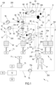
- the apparatus according to figure 1 is particularly (but not exclusively) designed for Renal Replacement Therapies (RRT) and particularly for Continuous Renal Replacement Therapies (CRRT).
- RRT Renal Replacement Therapies
- CRRT apparatuses are configured to deliver very specific treatments designed for patients versing in acute states of illness and who have temporarily lost their kidney function.
- CRRT systems may be structurally and/or operationally different from extracorporeal blood treatment systems designed for chronic patient care.
- CRRT systems need to exhibit specific technical features enabling the system to:
- the CRRT machine is dressed using an integrated disposable set 100, wherein all the lines and the filtration unit are grouped together and already properly connected in the disposable set. Further, all the fluids are normally (but not necessarily) contained in pre-packaged bags (dialysis fluid or replacement fluids in bags of e.g., 2, 5 or 10 litres each) or pre-packaged syringes (heparin and/or concentrated calcium replacement solution).
- pre-packaged bags dialysis fluid or replacement fluids in bags of e.g., 2, 5 or 10 litres each
- pre-packaged syringes heparin and/or concentrated calcium replacement solution
- the disposable set 100 comprises at least one filtration unit 2, which is configured to treat the blood withdrawn from the patient.
- the filtration unit 2 may be any kind of filter to treat blood, such as a filter for performing haemodialysis (HD), ultrafiltration (UF), haemofiltration (HF) and haemodiafiltration (HDF), for hemoperfusion, a plasmafilter, an adsorber, etc...
- HD haemodialysis
- UF ultrafiltration
- HF haemofiltration
- HDF haemodiafiltration
- the blood circuit 17 further comprises a pump tract 6p configured to engage a blood pump 21 of the extracorporeal blood apparatus to promote blood flow in the blood withdrawal line 6 and in the blood return line 7.
- the pump tract 6p may be arranged on the blood withdrawal line 6 or on the blood return line 7.
- the blood circuit 17 may comprise two blood pumps, wherein a first blood pump is engaged to the blood withdrawal line 6, and a second blood pump is engaged to the blood return line 7 (this embodiment is not shown).
- pump symbols in the drawings do not necessarily indicate the direction of the flow inside the respective pump tract.
- each and every (e.g., peristaltic) pump may be controlled in one direction and in the opposite direction, too, depending on the apparatus and therapy needs.
- the blood withdrawal line 6 includes the pump tract 6p that is engaged by the blood pump 21 of the extracorporeal blood treatment apparatus.
- the blood pump 21 is configured to determine a blood flow in a direction 200 from the second end 6b of the withdrawal line towards the filtration unit 2 and then to back to the blood return line 7.
- the blood pump tract 6p may be a portion of the blood withdrawal line 6 itself, which is interposed between the first end 6a and the second end 6b of the blood withdrawal line 6.
- the blood pump tract 6p may be different with respect to the other line tracts of the blood withdrawal line 6 in terms of dimension (e.g. passage section and/or wall thickness) and/or material.
- the blood pump tract 6p may have an external dimension, i.e. an external diameter, larger than an external dimension, i.e. an external diameter, of the first and/or second tracts of the blood withdrawal line 6.
- the blood pump tract 6p may have an internal dimension, i.e.
- the blood pump tract 6p may also be curved (e.g., a ⁇ shape) and/or may have elastic properties different from the properties of the first and the other line tracts of the blood withdrawal line 6: for example the blood pump tract 6p may be more flexible than the other line tracts of the blood withdrawal line 6 e.g., to withstand the fatigue stresses caused by the peristaltic pump 21 of the blood treatment apparatus.
- the blood withdrawal line 6 and the blood return line 7 are connected directly or indirectly to the blood cardiovascular system of the patient through an access device such as a needle, a catheter, or a graft.
- an access device such as a needle, a catheter, or a graft.
- the blood withdrawal line 6 and the blood return line 7 are directly connected to the blood cardiovascular system of the patient; however, in certain situations, such as when the patient is subject to a cardiopulmonary by-pass and therefore already connected to an ECMO machine, the blood withdrawal line 6 and the blood return line 7 may be connected to the ECMO extracorporeal blood lines and consequently indirectly connected to the blood cardiovascular system of the patient (via the ECMO blood lines).
- the apparatus 1 comprises a blood pump 21 for controlling the blood flow in the blood circuit 17.
- the blood pump 21 is generally a peristaltic pump acting either on the blood withdrawal line 6 (as shown e.g. in figures 1-5 ) and/or on the blood return line 7 (embodiment not shown).
- An operator may enter a set value for the blood flow rate through a user interface 15 and a control unit 12, during treatment, is configured to control the blood pump based on the set blood flow rate.
- Blood is withdrawn from the patient at a vascular access and flows through the blood withdrawal line 6; after passing through the primary chamber 3 of the filtration unit 2, where the suitable exchanges of substances, molecules and fluids occur through the semipermeable membrane 5, the treated blood enters the blood return line 7, first passing through the air separator, commonly known as "bubble trap", 19 designed to ensure removal of air bubbles present in the blood.
- the treated blood getting out of the bubble trap 19, before being returned to the patient P passes through an air bubble sensor 55 verifying the absence of air bubbles within the treated blood that has to be re-introduced in the patient's blood vascular circuit at the venous access.
- a corresponding safety valve 27 may be present on the blood withdrawal line 6 close to the patient vascular access to fully isolate the patient from the extracorporeal blood circuit in case of need.
- the safety valve 27 of the blood withdrawal line 6 and the safety valve 20 of the blood return line 7 may be arranged both in the close position so that the patient P is fluidly isolated from the blood circuit 17 of the disposable set.
- the safety valve 27 of the blood withdrawal line 6 and the safety valve 20 of the blood return line 7 may be manually controllable, but are usually automatically controllable by the control unit 12 between the close position and the open position, and vice versa.
- the disposable set 100 further comprises an infusion line 63 extending from a first end 63a, for connection to an infusion fluid source 64, and a branch site 67 branching off the infusion line 63 towards a second end 63b and towards a third end 63c.
- the portion of the infusion line 63 interposed between the second end 63b and the third end 63c of the infusion line 63 defines a recirculation portion 66 of the infusion line, as described in more detail here-after in the present description.
- the fluid source 64 is a source of infusion or replacement fluid.
- the fluid source 64 may be a plastic bag housing a pre-packaged replacement fluid solution.
- the second end 63b of the infusion line 63 is in direct or indirect fluid communication with the blood withdrawal line 6 at a first site 31.
- a direct fluid communication between the infusion line 63 and the blood withdrawal line 6 means that the infusion line 63 is directly connected to the blood withdrawal line 6 and the fluid exiting the second end 63b of the infusion line 63 enters directly into the blood stream flowing in the blood withdrawal line 6 of the blood circuit 17.
- An indirect fluid communication between the infusion line 63 and the blood withdrawal line 6 means that the infusion line 63 is not directly connected to the blood withdrawal line 6, but to another fluid line (e.g., PBP line 51) that is itself directly connected to the blood withdrawal line 6.
- PBP line 51 another fluid line
- the infusion fluid exiting the second end 63b of the infusion line 63 enters the other fluid line and then reaches the blood withdrawal line 6 at the injection point of the other line into the blood withdrawal line 6.
- the first site 31 is located on the blood circuit 17 and is specifically arranged on the blood withdrawal line 6 and is interposed between the blood pump tract 6p and the second end 6b of the blood withdrawal line 6. Even though not essential, the first site 31 may be arranged as close as possible to the patient, so that the remaining portion of the withdrawal line 6 between the first site 31 and the patient is as short as possible. The first site 31 is upstream the blood pump tract 6p with respect to the blood withdrawal direction 200.
- the first site 31 may or may not coincide with the second end 63b of the infusion line 63.
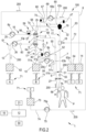
- the first site 31 is coincident with the location where the second end 63b of the infusion line 63 (directly) connects to the blood withdrawal line 6 (e.g., fig. 1 ); in other embodiments, the first site 31 (which is on the blood withdrawal line 6) may be distinct and spatially separated from the second end 63b of the infusion line 63 (e.g., fig. 2 ).
- the first site 31 may comprise a fluid connector, i.e. a three-way fluid connector, including a blood inlet (directly) fluidly connected to the withdrawal line 6 and facing the second end 6b of the blood withdrawal line 6, a blood outlet (directly) fluidly connected to the withdrawal line 6 and facing the first end 6a of the blood withdrawal line 6, in particular facing the pump tract 6p of the blood withdrawal line 6, and an infusion inlet (directly or indirectly) in fluid communication with the second end 63b of the infusion line 63.
- a fluid connector i.e. a three-way fluid connector, including a blood inlet (directly) fluidly connected to the withdrawal line 6 and facing the second end 6b of the blood withdrawal line 6, a blood outlet (directly) fluidly connected to the withdrawal line 6 and facing the first end 6a of the blood withdrawal line 6, in particular facing the pump tract 6p of the blood withdrawal line 6, and an infusion inlet (directly or indirectly) in fluid communication with the second end 63b of the infusion line 63.
- the fluid connector may be made by plastic material stiffer than the material of the infusion line 63 and/or of the blood withdrawal line 6.
- the infusion line 63 is flexible, in particular more flexible than the fluid connector.
- the blood withdrawal line 6 is more flexible than the fluid connector.
- the first site 31 is distinct and spatially separated from the second end 6b of the blood withdrawal line 6.
- the third 63c end of the infusion line 63 is in direct or indirect fluid communication with the blood return line 7 at a second site 32.
- the second site 32 is interposed between the blood pump tract 6p and the second end 7b of the blood return line 7.
- the second site 32 is interposed between the blood outlet 2b of the filtration unit 2 and the second end 7b of the return line 7.
- the second site 32 may comprise a fluid connector, too, i.e. a three-way fluid connector, including a blood inlet (directly) fluidly connected to the return line 7 and facing the first end 7a of the blood return line 7, a blood outlet (directly) fluidly connected to the return line 7 and facing the second end 7b of the blood return line 7, and an infusion inlet (directly or indirectly) in fluid communication with the third end 63c of the infusion line 63.
- a bubble trap 19 may be located at the second site 32 arranged on the blood return line 7.
- the bubble trap 19 includes a blood inlet (directly) fluidly connected to the return line 7 and facing the first end 7a of the blood return line 7, a blood outlet (directly) fluidly connected to the return line 7 and facing the second end 7b of the blood return line 7, and an infusion inlet (directly) fluidly connected to the third end 63c of the infusion line 63.
- the bubble trap 19 is configured to separate air/gas bubbles from the blood stream, in order to prevent bubbles to flow towards the patient.
- the second site 32 is distinct and spatially separated from the second end 7b of the blood return line 7.
- the infusion line 63 extends from the first end 63a thereof for a first tract 72 up to the branch site 67, where the first tract 72 branches into a second tract 68, extending from the branch site 67 up to the second end 63b of the infusion line 63, and into a third tract 69 extending from the branch site 67 up to the third end 63c of the infusion line 63.
- a recirculation portion 66 of the infusion line 63 comprises (and may be entirely defined by - in the case of figures 1 , 1a , 4 , 4a , 5 , and 5a ) the second tract 68 and the third tract 69 of the infusion line 63.
- the infusion line 63 further comprises a respective infusion pump tract 65p, interposed between the first end 63a and the branch site 67 of the infusion line 63; the infusion pump tract 65p of the infusion line 63 is configured to be engaged by a respective infusion pump 65 of the extracorporeal blood treatment apparatus, i.e. an occlusive pump such as a peristaltic pump, configured to cause a fluid flow in a direction from the first end 63a of the infusion line towards the branch site 67.
- the infusion pump tract 65p may comprise the same technical features previously described and differentiating the blood pump tract 6p from the other line tracts of the blood withdrawal line 6.
- the apparatus 1 includes the infusion pump 65 (in the example a peristaltic pump) engaged to the infusion line 63 and configured to determine, during infusion, the flow rate along the line of the substance housed in the infusion fluid source 64, i.e. replacement fluid.
- the infusion pump 65 in the example a peristaltic pump engaged to the infusion line 63 and configured to determine, during infusion, the flow rate along the line of the substance housed in the infusion fluid source 64, i.e. replacement fluid.
- the extracorporeal blood treatment apparatus 1 may further comprise a selector 70 active on the infusion line 63 at the branch site 67.
- the selector 70 may be switchable (at least) between:
- both the second tract 68 and the third tract 69 of the infusion line 63 define the recirculation portion 66 of the loop recirculation circuit 11.
- the selector 70 in the recirculation position, the selector 70 (which may be a valve clamping either the second tract 68 or the third tract 69 or none of the tubes 68, 69) is not acting on (clamping) any tube portions and is in a neutral and distanced position from the second and third tracts 68, 69.
- the infusion pump 65 may be an occlusive pump and may be inactive thereby preventing any flow; alternatively, a clamp, the same selector 70, or another device may prevent flow in the first tract 72 e.g., by closing it.
- fluid flows from the first tract 72 towards the second and/or third tracts 68, 69 and infuse replacement fluid in the blood circuit.
- the cooperation between an active infusion pump 65 and the selector 70 may define the quantity of fluid pre-infused and the quantity of fluid simultaneously post-infused.
- the selector 70 prevents fluid communication between the first site 31 and the second site 32 through the recirculation portion 66 of the loop recirculation circuit 11.
- the first operating position the passage of fluid from the fluid source 64 to the second tract 68 is allowed, while the passage of fluid from the fluid source 64 to the third tract 69 is prevented.
- the second operating position the passage of fluid from the fluid source 64 to the third tract 69 is allowed, while the passage of fluid from the fluid source 64 to the second tract 68 is prevented.
- first operating position and the second operating position may be taken during a standard dialysis treatment to either pre- or post-infuse a replacement fluid into the extracorporeal blood circuit, while the recirculation position of selector 70 is taken to allow fluid recirculation in the recirculation condition.
- Selector 70 may consist of a valve element operating on the infusion line 63 by alternatively blocking the passage of fluid in either branch and further placeable in the neutral position. Suitable selectors may be alternatively provided, which are able to establish a priori the amount of liquid that has to pass through both branches simultaneously. It will also be possible to vary the percentages of fluid in either branch as a function of time and of the pre-established therapies.
- the selector 70 is connected to the control unit 12, wherein the latter is configured to control selectively the selector in said first operating position, in the second operating position and in the recirculation position.
- the disposable set may further comprise a pre-blood-pump (PBP) infusion line 51 extending from a first end 51a for connection to a second fluid source 10, and a second end 51b fluidly connected to the blood withdrawal line 6.
- the pre-blood-pump infusion line 51 may be an anticoagulant infusion line 51; in such a case the second fluid source 10 may house a fluid solution including citrate and/or citric acid.
- the second fluid source 10 may be a plastic bag housing the PBP infusion fluid.
- the second end 51b of the pre-blood-pump infusion line 51 is interposed between the second end 6b of the blood withdrawal line 6 and the blood pump tract 6p as shown in figures 1 and 2 .
- the second end 51b of the pre-blood-pump infusion line 51 may be interposed between the second end 6b of the blood withdrawal line 6 and the first site 31 as shown in figure 1 in case of direct connection of the infusion line 63 to the blood withdrawal line 6. Indeed, in such a case, connection between second end 63b of the infusion line 63 and the withdrawal line is optionally downstream the second end 51b of the pre-blood-pump infusion line 51.
- the pre-blood-pump infusion line 51 also comprises a respective PBP (pre-blood-pump) infusion pump tract 51p configured to be engaged by a respective PBP infusion pump 54 configured to infuse the substance from the second fluid source 10 through the pre-blood-pump infusion line 51 and into the blood circuit 17.
- PBP pre-blood-pump
- the PBP infusion pump 54 is operatively connected to the control unit 12 which is configured to selectively control the PBP infusion pump 54 to promote the infusion fluid to flow within the infusion line 51 and to deliver the infusion fluid into the blood withdrawal line 6: the control unit 12 may be configured to control the PBP infusion pump 54 to set the prescription flow rate. Also in this regard, the type of treatment, the infusion bag content, and other conditions determine the set infusion rate. The control unit may also be configured to stop the PBP infusion pump 54 to arrest delivery of the infusion fluid.
- the second end 51b of the pre-blood-pump infusion line 51 is connected to the blood withdrawal line 6 at the first site 31.
- the second tract 68 of the infusion line 63 is directly connected to the pre-blood-pump infusion line 51 at an access point 51c interposed between the second end 51b of the pre-blood-pump infusion line 51 and the PBP infusion pump tract 51p of the pre-blood-pump infusion line 51.
- the infusion line 63 and the pre-blood-pump infusion line 51 are connected together, at the access point 51c, and fluid moves towards the blood withdrawal line 6 along a common infusion tract extending up to the first site 31 (i.e., the common infusion tract runs from the access point 51c to the second end 51b of the pre-blood-pump infusion line 51).
- the disposable set further comprises an ion replacement fluid line 74 connected, on one end, to an ion replacement container 73 and, to the other end, to the blood return line (7), for example at an access site 18, such as a connector allowing infusion and homogenous mixing of the infused fluid with the blood.
- an access site 18 is placed downstream the second site 32 and possibly, but not necessarily, upstream the air bubble sensor 55.
- An ion replacement pump 75 acting on a ion replacement pump tract 75p allow to pump the fluid through the ion replacement infusion line 74.
- the ion replacement infusion line 74 is directly connected to an additional patient vascular access directly infusing the ion replacement fluid into the patient blood (e.g., into a venous peripheral vessel of the patient).
- the ion replacement infusion line 74 is used to infuse a calcium (and possibly a magnesium, too) concentrated solution to re-establish the proper electrolyte balance in the patient blood during treatments with regional anticoagulation using citrate.
- the disposable set 100 further comprises a fluid supply line 8.
- the fluid supply line 8 delivers dialysis fluid from a dialysis liquid source 14 to the filtration unit 2.
- the dialysis liquid source 14 consists of one or more bags containing a suitable dialysis liquid designed to supply the supply line 8 of the dialysis fluid circuit 16 with dialysis fluid.
- the dialysis liquid supply line 8 also comprises a respective supply pump tract 8p configured to be engaged by a dialysis fluid pump 25 of the extracorporeal blood treatment apparatus to promote dialysis fluid flow towards the fluid inlet of the secondary chamber 4 of the filtration unit.
- the dialysis fluid pump 25 i.e. a peristaltic pump, defines a direction 200 of dialysis fluid circulation and controls the flow rate of the fresh dialysis liquid from the bag 64 towards the filtration unit 2.
- a branching 56 is provided splitting the dialysis supply line 8 up into an intake branch 57 and a post infusion tract 58.
- the supply line 8 splits in a post infusion tract 58 extending up to the return line 7 so that the fluid supply line 8 is fluidly connected to the return line 7 of the blood circuit 17.
- infusion branch 58 By means of said infusion branch 58 it is possible to obtain a post-infusion directly in the blood line 17 using the content of the primary fluid container 64.
- the loop recirculation circuit 11 is configured to allow blood to continuously flow within the loop recirculation circuit 11 in loop: the blood pump 21, engaged to the blood pump tract 6p, is configured to determine the blood flow within the loop recirculation circuit 11.
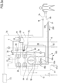
- the loop recirculation circuit is shown, with bold lines, in figures 1a , 2a , and according to specific embodiments of the disposable set 100, in figures 3a , 4a , and 5a .
- blood recirculation in the loop recirculation circuit 11 may be started without stopping the blood pump 21. Indeed, it is sufficient that the control unit 12 sets the disposable in a configuration that allows the blood pushed by the blood pump 21 to recirculate in the loop recirculation circuit 11. It might be sufficient to allow blood to flow along the third tract 69 and the second tract 68 of the infusion line 63. To achieve this configuration, the selector 70 is moved to the recirculation position (neutral position). No infusion of fluid through infusion line 63 is commanded (i.e., infusion pump 65 is stopped).
- control unit 12 is configured to perform a rinsing step of infusion line 63, and in particular of the second tract 68 of the infusion line 63 where blood was recirculated.
- the control unit 12 commands a specific (higher) flow rate through the second tract 68 of the infusion line 63.
- the third tract 69 of the infusion line 63 is rinsed.
- the control unit 12 is configured to move the selector 70 to post-infusion (second operating position) and to wash blood away from the third tract 69.
Landscapes
- Health & Medical Sciences (AREA)
- Heart & Thoracic Surgery (AREA)
- Engineering & Computer Science (AREA)
- Cardiology (AREA)
- Life Sciences & Earth Sciences (AREA)
- Anesthesiology (AREA)
- Biomedical Technology (AREA)
- Hematology (AREA)
- Animal Behavior & Ethology (AREA)
- General Health & Medical Sciences (AREA)
- Public Health (AREA)
- Veterinary Medicine (AREA)
- Vascular Medicine (AREA)
- Mechanical Engineering (AREA)
- Pulmonology (AREA)
- Urology & Nephrology (AREA)
- External Artificial Organs (AREA)
Abstract
Description
- The present invention relates to a disposable set for an extracorporeal blood treatment apparatus configured to allow for fluid/blood recirculation in loop, for example when an alarm is issued stopping the blood pump, and the treatment has to be (e.g., temporarily) interrupted.
- The invention also relates to an apparatus for extracorporeal blood treatment and to a procedure to perform fluid/blood recirculation in loop in a disposable set of an extracorporeal blood treatment apparatus.
- The extracorporeal blood treatment apparatus of the present invention may perform dialysis treatments such as hemodialysis (HD) treatments, hemofiltration (HF) treatments, hemodiafiltration (HDF) treatments, or ultrafiltration (UF) treatments, as well as Continuous Renal Replacement Therapy (CRRT) treatments; the apparatus may also be configured for ECCO2R or oxygenation treatments, as well as for adsorption, hemoperfusion, liver treatments, or plasmapheresis.
- The kidneys fulfil many functions, including the removal of water, the excretion of catabolites (or waste from the metabolism, for example urea and creatinine), the regulation of the concentration of the electrolytes in the blood (e.g. sodium, potassium, magnesium, calcium, bicarbonates, phosphates, chlorides) and the regulation of the acid/base equilibrium within the body, which is obtained in particular by the removal of weak acids and by the production of ammonium salts. In individuals who have lost (temporarily or permanently) the use of their kidneys, since these excretion and regulation mechanisms no longer work, the body accumulates water and waste from the metabolism and exhibits an excess of electrolytes, as well as, in general, acidosis, the pH of the blood plasma shifting downwards, below 7.35 (the blood pH normally varies within narrow limits of between 7.35 and 7.45). As mentioned, in order to overcome renal dysfunction, resort is conventionally made to a blood treatment involving extracorporeal circulation through an exchanger having a semipermeable membrane (dialyzer) in which the patient's blood is circulated on one side of the membrane and a dialysis liquid, comprising the main electrolytes of the blood in concentrations close to those in the blood of a healthy subject, is circulated on the other side. Furthermore, a pressure difference is created between the two compartments of the dialyzer which are delimited by the semipermeable membrane, so that a fraction of the plasma fluid passes by ultrafiltration through the membrane into the compartment containing the dialysis liquid. The blood treatment which takes place in a dialyzer as regards waste from the metabolism and electrolytes results from two mechanisms of molecular transport through the membrane. On the one hand, the molecules migrate from the liquid where their concentration is higher to the liquid where their concentration is lower. This is diffusive transport. On the other hand, certain catabolites and certain electrolytes are entrained by the plasma fluid which filters through the membrane under the effect of the pressure difference created between the two compartments of the exchanger. This is convective transport. Three of the abovementioned functions of the kidney, namely the removal of water, the excretion of catabolites and the regulation of the electrolytic concentration of the blood, are therefore performed in a conventional blood treatment device by the combination of dialysis and blood filtration (this combination is referred to as hemodiafiltration). To perform one or more of the above described treatments, the extracorporeal blood treatment equipment may comprise a disposable set including a plurality of lines for delivering fluid directly to the patient or into the extracorporeal blood circuit.
- The disposable set for extracorporeal blood treatment commonly comprises a fluid circuit including fluid lines, blood lines and a filtration unit. The disposable set is usually engaged to a front panel of an extracorporeal blood treatment apparatus for delivering any one of the above mentioned treatments.
- In case of extracorporeal blood circulation, one relevant concern includes reducing the risk of blood clotting within the blood lines of the disposable set.
- However, during an extracorporeal blood treatment, it may be necessary to stop the blood pump (i.e., stop the extracorporeal blood circulation) when the extracorporeal blood is still in the blood circuit of the apparatus, for example, when an alarm is issued requiring to temporally suspend the treatment to allow the operator to fix the problem. In such a situation, the blood remains stationary in the blood lines increasing the risk of blood clotting both in the blood lines and in the filtration unit. Blood clotting risk increases with passing time, therefore, the operator should be able to resume the treatment in the shortest time possible. In such alarm situations with the blood pump stopped, stressful situations are caused on the operators, particularly the less experienced ones. In case blood clots in the lines and/or in the filtration unit, the disposable set has to be disposed and replaced with a new one. This leads to substantive loss of blood from the patient and determines an increase of the treatment costs and time.
- The aim of the invention is therefore to at least partially solve one or more of the drawbacks and/or limitations described above.
- A first aim is to reduce the risk of clotting in the extracorporeal blood circuit by prevention of blood stagnation. A further object is to more easily address alarms that stop the blood pump and thus induce a risk of circuit clotting if troubleshooting is delayed, preventing, or at least reducing, the risk of blood clotting in the lines of the disposable set.
- A further aim is to give the practitioner more time (thus also reducing stress) for troubleshooting, such as fixing treatment or patient issues and/or resetting apparatus parameters, during the temporary interruption in the treatment.
- An additional aim is to improve the life time of the disposable set, which is particularly relevant in CRRT therapies.
- A further aim is to avoid the blood volume housed in the disposable set to be discarded, which results in blood loss for the patient and the disposal of the circuit, thus also reducing waste during extracorporeal blood treatments.
- An auxiliary aim is to allow for recirculation in the blood withdrawal line to the maximum extent possible so to avoid blood stagnation in a long portion of the blood lines.
- These objects and more, which will appear more from the following description, are substantially achieved by a disposable set, an apparatus, and a recirculation procedure in accordance with one or more of the following claims and/or aspects.
- Not all aims may be achieved by each and every embodiment of the invention.
- The disposable set of the invention is according to the feature combination of claim 1. The apparatus of the invention is according to the feature combination of
claim 13. - A first aspect refers to an extracorporeal blood treatment apparatus including:
- one or more pumps (21, 25, 26, 54, 65, 75) comprising a blood pump (21),
- one or more intercepting elements (20, 27, 59, 70),
- a disposable set (100) comprising:
- ➢ a filtration unit (2) having a blood inlet (2a) and a blood outlet (2b);
- ➢ a blood circuit (17) including:
- ▪ a blood withdrawal line (6) extending between a first end (6a) connected to the blood inlet (2a) of the filtration unit (2), and a second end (6b) for connection to a patient (P);
- ▪ a blood return line (7) extending between a first end (7a) connected to the blood outlet (2b) of the filtration unit (2), and a second end (7b) for connection to the patient;
- ▪ a blood pump tract (6p) located on the blood circuit (17) and engaged to the blood pump (21) of the extracorporeal blood treatment apparatus to promote blood flow in the blood circuit,
- > an infusion line (63) extending from a first end (63a) for connection to an infusion fluid source (64) and branching off at a branch site (67) towards:
- ▪ a second end (63b) of the infusion line (63) in direct or indirect fluid communication with the blood withdrawal line (6) at a first site (31), the first site (31) being interposed between the second end (6b) of the blood withdrawal line (6) and the blood pump tract (6p); and
- ▪ a third end (63c) of the infusion line (63) in direct or indirect fluid communication with the blood return line (7) at a second site (32), the second site (32) being interposed between the blood pump tract (6p) and the second end of the blood return line (7);
- a control unit (12) configured to control said one or more pumps (21, 25, 26, 54, 65, 75) and said one or more intercepting elements (20, 27, 59, 70) in order to define different flow circuits inside the blood circuit (17) and the infusion line (63), the control unit (12) being configured to define at least the following flow circuits:
- ➢ a treatment flow circuit, wherein the one or more pumps (21, 25, 26, 54, 65, 75) and the one or more intercepting elements (20, 27, 59, 70) are configured to allow blood to flow from the second end (6b) of the blood withdrawal line (6) to the filtration unit (2) and from the filtration unit (2) to the second end (7b) of the blood return line (7); and
- ➢ a loop recirculation circuit (11), wherein the one or more pumps (21, 25, 26, 54, 65, 75) and the one or more intercepting elements (20, 27, 59, 70) are configured to allow blood or a fluid to continuously flow in a loop circulation,
- the filtration unit (2);
- the blood pump tract (6p);
- a portion of the blood withdrawal line (6) interposed between the first site (31) of the blood withdrawal line (6) and the blood inlet (2a) of the filtration unit (2);
- a portion of the blood return line (7) interposed between the blood outlet (2b) of the filtration unit (2) and the second site (32) of the blood return line (7);
- a recirculation portion (66) of the infusion line (63) downstream the branch site (67) and interposed between the first site (31) and the second site (32).
- In a 2nd independent aspect a disposable set (100) for an extracorporeal blood treatment apparatus (1) is provided comprising:
- a filtration unit (2) having a blood inlet (2a) and a blood outlet (2b);
- a blood circuit (17) including:
- > a blood withdrawal line (6) extending between a first end (6a) connected to the blood inlet (2a) of the filtration unit (2), and a second end (6b) for connection to a patient (P);
- ➢ a blood return line (7) extending between a first end (7a) connected to the blood outlet (2b) of the filtration unit (2), and a second end (7b) for connection to the patient;
- ➢ a blood pump tract (6p) located on the blood circuit (17) and configured to be engaged to a blood pump (21) of the extracorporeal blood treatment apparatus to promote blood flow in the blood circuit,
- an infusion line (63) extending from a first end (63a) for connection to an infusion fluid source (64) and branching off at a branch site (67) towards:
- ➢ a second end (63b) of the infusion line (63) in direct or indirect fluid communication with the blood withdrawal line (6) at a first site (31), the first site (31) being interposed between the second end (6b) of the blood withdrawal line (6) and the blood pump tract (6p); and
- ➢ a third end (63c) of the infusion line (63) in direct or indirect fluid communication with the blood return line (7) at a second site (32), the second site (32) being interposed between the blood pump tract (6p) and the second end of the blood return line (7);
- the filtration unit (2);
- the blood pump tract (6p);
- a portion of the blood withdrawal line (6) interposed between the first site (31) of the blood withdrawal line (6) and the blood inlet (2a) of the filtration unit (2);
- a portion of the blood return line (7) interposed between the blood outlet (2b) of the filtration unit (2) and the second site (32) of the blood return line (7);
- a recirculation portion (66) of the infusion line (63) downstream the branch site (67) and interposed between the first site (31) and the second site (32);
- In a 3rd independent aspect a method of recirculating blood in an extracorporeal blood treatment apparatus (1) is provided, wherein the apparatus (1) includes:
- one or more pumps (21, 25, 26, 54, 65, 75) comprising a blood pump (21),
- one or more intercepting elements (20, 27, 59, 70),
- a disposable set (100), particularly in accordance with any one of the previous claims, comprising:
- ➢ a filtration unit (2) having a blood inlet (2a) and a blood outlet (2b);
- ➢ a blood circuit (17) including:
- ▪ a blood withdrawal line (6) extending between a first end (6a) connected to the blood inlet (2a) of the filtration unit (2), and a second end (6b) for connection to a patient (P);
- ▪ a blood return line (7) extending between a first end (7a) connected to the blood outlet (2b) of the filtration unit (2), and a second end (7b) for connection to the patient;
- ▪ a blood pump tract (6p) located on the blood circuit (17) and engaged to the blood pump (21) of the extracorporeal blood treatment apparatus to promote blood flow in the blood circuit,
- > an infusion line (63) extending from a first end (63a) for connection to an infusion fluid source (64) and branching off at a branch site (67) towards:
- ▪ a second end (63b) of the infusion line (63) in direct or indirect fluid communication with the blood withdrawal line (6) at a first site (31), the first site (31) being interposed between the second end (6b) of the blood withdrawal line (6) and the blood pump tract (6p); and
- ▪ a third end (63c) of the infusion line (63) in direct or indirect fluid communication with the blood return line (7) at a second site (32), the second site (32) being interposed between the blood pump tract (6p) and the second end of the blood return line (7);
- a control unit (12) configured to control said one or more pumps (21, 25, 26, 54, 65, 75) and said one or more intercepting elements (20, 27, 59, 70) in order to define different flow circuits inside the blood circuit (17) and the infusion line (63),
- wherein the method of recirculating blood comprises switching from:
- ➢ a treatment flow circuit, wherein the one or more pumps (21, 25, 26, 54, 65, 75) and the one or more intercepting elements (20, 27, 59, 70) allow blood to flow from the second end (6b) of the blood withdrawal line (6) to the filtration unit (2) and from the filtration unit (2) to the second end (7b) of the blood return line (7); to
- ➢ a loop recirculation circuit (11), wherein the one or more pumps (21, 25, 26, 54, 65, 75) and the one or more intercepting elements (20, 27, 59, 70) allow blood or a fluid to continuously flow in a loop circulation,
- wherein the loop recirculation circuit (11) includes:
- the filtration unit (2);
- the blood pump tract (6p);
- a portion of the blood withdrawal line (6) interposed between the first site (31) of the blood withdrawal line (6) and the blood inlet (2a) of the filtration unit (2);
- a portion of the blood return line (7) interposed between the blood outlet (2b) of the filtration unit (2) and the second site (32) of the blood return line (7);
- wherein the method of recirculating blood comprises switching from:
- In a 4th independent aspect an extracorporeal blood treatment apparatus including:
- one or more pumps (21, 25, 26, 54, 65, 75) comprising a blood pump (21),
- one or more intercepting elements (20, 27, 59, 70),
- a disposable set (100) comprising:
- ➢ a filtration unit (2) having a blood inlet (2a) and a blood outlet (2b);
- ➢ a blood circuit (17) including:
- ▪ a blood withdrawal line (6) extending between a first end (6a) connected to the blood inlet (2a) of the filtration unit (2), and a second end (6b) for connection to a patient (P);
- ▪ a blood return line (7) extending between a first end (7a) connected to the blood outlet (2b) of the filtration unit (2), and a second end (7b) for connection to the patient;
- ▪ a blood pump tract (6p) located on the blood circuit (17) and engaged to the blood pump (21) of the extracorporeal blood treatment apparatus to promote blood flow in the blood circuit,
- > a pre-blood-pump infusion line (51) extending from a first end (51a) for connection to a second fluid source (10), and a second end (51b) fluidly connected to the blood withdrawal line (6) between the second end (6b) of the blood withdrawal line (6) and the blood pump tract (6p);
- > an infusion line (63) extending from a first end (63a) for connection to an infusion fluid source (64) and branching off at a branch site (67) towards:
- ▪ a second end (63b) of the infusion line (63) directly connected to the pre-blood-pump infusion line (51) and in fluid communication with the blood withdrawal line (6) at a first site (31), the first site (31) being interposed between the second end (6b) of the blood withdrawal line (6) and the blood pump tract (6p); and
- ▪ a third end (63c) of the infusion line (63) in direct or indirect fluid communication with the blood return line (7) at a second site (32), the second site (32) being interposed between the blood pump tract (6p) and the second end of the blood return line (7);
- a control unit (12) configured to control said one or more pumps (21, 25, 26, 54, 65, 75) and said one or more intercepting elements (20, 27, 59, 70) in order to define different flow circuits inside the blood circuit (17) and the infusion line (63), the control unit (12) being configured to define at least the following flow circuits:
- > a treatment flow circuit, wherein the one or more pumps (21, 25, 26, 54, 65, 75) and the one or more intercepting elements (20, 27, 59, 70) are configured to allow blood to flow from the second end (6b) of the blood withdrawal line (6) to the filtration unit (2) and from the filtration unit (2) to the second end (7b) of the blood return line (7); and
- ➢ a loop recirculation circuit (11), wherein the one or more pumps (21, 25, 26, 54, 65, 75) and the one or more intercepting elements (20, 27, 59, 70) are configured to allow blood or a fluid to continuously flow in a loop circulation,
- the filtration unit (2);
- the blood pump tract (6p);
- a portion of the blood withdrawal line (6) interposed between the first site (31) of the blood withdrawal line (6) and the blood inlet (2a) of the filtration unit (2);
- a portion of the blood return line (7) interposed between the blood outlet (2b) of the filtration unit (2) and the second site (32) of the blood return line (7);
- a recirculation portion (66) of the infusion line (63) downstream the branch site (67) and interposed between the first site (31) and the second site (32)
- the common infusion tract.
- In a 5th independent aspect a disposable set (100) for an extracorporeal blood treatment apparatus (1) is provided comprising:
- a filtration unit (2) having a blood inlet (2a) and a blood outlet (2b);
- a blood circuit (17) including:
- > a blood withdrawal line (6) extending between a first end (6a) connected to the blood inlet (2a) of the filtration unit (2), and a second end (6b) for connection to a patient (P);
- ➢ a blood return line (7) extending between a first end (7a) connected to the blood outlet (2b) of the filtration unit (2), and a second end (7b) for connection to the patient;
- ➢ a blood pump tract (6p) located on the blood circuit (17) and configured to be engaged to a blood pump (21) of the extracorporeal blood treatment apparatus to promote blood flow in the blood circuit,
- a pre-blood-pump infusion line (51) extending from a first end (51a) for connection to a second fluid source (10), and a second end (51b) fluidly connected to the blood withdrawal line (6) between the second end (6b) of the blood withdrawal line (6) and the blood pump tract (6p);
- an infusion line (63) extending from a first end (63a) for connection to an infusion fluid source (64) and branching off at a branch site (67) towards:
- > a second end (63b) of the infusion line (63) directly connected to the pre-blood-pump infusion line (51) and in fluid communication with the blood withdrawal line (6) at a first site (31), the first site (31) being interposed between the second end (6b) of the blood withdrawal line (6) and the blood pump tract (6p); and
- ➢ a third end (63c) of the infusion line (63) in direct or indirect fluid communication with the blood return line (7) at a second site (32), the second site (32) being interposed between the blood pump tract (6p) and the second end of the blood return line (7);
- the filtration unit (2);
- the blood pump tract (6p);
- a portion of the blood withdrawal line (6) interposed between the first site (31) of the blood withdrawal line (6) and the blood inlet (2a) of the filtration unit (2);
- a portion of the blood return line (7) interposed between the blood outlet (2b) of the filtration unit (2) and the second site (32) of the blood return line (7);
- a recirculation portion (66) of the infusion line (63) downstream the branch site (67) and interposed between the first site (31) and the second site (32);
- the common infusion tract;
- In the following depending aspects, features of the disposable set are provided which may be implemented in combination with the apparatus, disposable set, and method of the previous aspects.
- In a 6th aspect according to any one of the previous aspects, the loop recirculation circuit (11) is configured to allow fluid recirculation in a first direction from the first site (31) towards the filtration unit (2) and from the filtration unit (2) towards the second site (32) or in an second direction from the second site (32) towards the filtration unit (2) and from the filtration unit (2) towards the first site (31).
- In a 7th aspect according to any one of the previous aspects:
- the blood inlet (2a) of the filtration unit (2) is in bidirectional fluid communication with the recirculation portion (66) of the infusion line (63) through the first site (31); and
- the blood outlet (2b) of the filtration unit (2) is in bidirectional fluid communication with the recirculation portion (66) of the infusion line (63) through the second site (32).
- In an 8th aspect according to any one of the previous aspects, the second end (63b) of the infusion line (63) is directly connected to the blood withdrawal line (6) at a first site (31).
- In a 9th aspect according to any one of the previous aspects, the first site (31) comprises a fluid connector, in particular a three-way fluid connector, including:
- a blood inlet fluidly connected to the withdrawal line (6) and facing the second end (6b) of the blood withdrawal line (6);
- a blood outlet fluidly connected to the withdrawal line (6) and facing the first end (6a) of the blood withdrawal line (6), optionally facing the pump tract (6p) of the blood withdrawal line (6);
- an infusion inlet fluidly connected to the recirculation portion (66) of the infusion line (63), and in particular fluidly connected to the second end (63b) of the infusion line (63).
- In a 10th aspect according to any one of the previous aspects, the disposable set further comprises at least one pressure detecting site (48a; 49a) arranged on the blood withdrawal line (6) between the first site (31) and the filtration unit (2), in particular said at least one pressure detecting site (48a; 49a) being a pressure pod.
- In a 11th aspect according to any one of the previous aspects, the disposable set further comprises a pressure detecting site (48a) arranged on the blood withdrawal line (6) between the first site (31) and the blood pump tract (6p), in particular said pressure detecting site (48a) being a pressure pod.
- In a 12th aspect according to any one of the previous aspects, the disposable set further comprises a pressure detecting site (49a) arranged on the blood withdrawal line (6) between the blood pump tract (6p) and the filtration unit (2), in particular said pressure detecting site (49a) being a pressure pod.
- In a 13th aspect according to any one of the previous aspects, the disposable set further comprises a pressure detecting site (50a) arranged on the infusion line (63) between the branch site (67) and the second end (63b) of the infusion line (63).
- In a 14th aspect according to any one of the previous aspects:
- the pump tract (6p) is arranged on the blood withdrawal line (6), in particular interposed between the first site (31) and the first end (6a) of the blood withdrawal line (6);
or - the pump tract (6p) is arranged on the blood return line (7), in particular between the first end (7a) of the blood return line (7) and the second site (32).
- In a 15th aspect according to any one of the previous aspects, the first site (31) is arranged on the blood withdrawal line (6) upstream the blood pump tract (6p) with respect to a blood withdrawal direction (200) directed from the second end (6b) to the first end (6a) of the blood withdrawal line (6), in particular the first site (31) being arranged upstream a blood pump (21) of the extracorporeal blood treatment apparatus configured to act on the blood pump tract (6p) of the blood withdrawal line (6).
- In a 16th aspect according to any one of the previous aspects, the infusion line (63) extends from the first end (63a) of the infusion line (63) for a first tract (72), said first tract (72) branching at the branch site (67) in:
- a second tract (68) extending from the branch site (67) up to the second end (63b) of the infusion line (63); and
- a third tract (69) extending from the branch site (67) up to the third end (63c) of the infusion line (63), the recirculation portion (66) of the infusion line (63) comprising the second tract (68) and the third tract (69) of the infusion line (63).
- In a 17th aspect according to the previous aspect, the infusion line (63) comprises a respective infusion pump tract (65p) configured to be engaged by an infusion pump (65) of the extracorporeal blood treatment apparatus, said infusion pump tract (65p) being interposed between the first end (63a) and the branch site (67) of the infusion line (63).
- In an 18th aspect according to the previous aspect, the infusion pump tract (65p) of the infusion line (63) is arranged on the first tract (72) of the infusion line (63), in particular the infusion pump tract (65p) being part of the first tract (72) of the infusion line (63).
- In a 19th aspect according to any one of the previous aspects, the fluid source (64) comprises a pre-packaged bag containing a replacement solution.
- In a 20th aspect according to any one of the previous aspects, the third end (63c) of the infusion line (63) is directly connected to the blood return line (7) at the second site (32).
- In a 21st aspect according to any one of the previous aspects, the disposable set comprises a bubble trap (19) arranged on the return line (7) of the blood circuit (17), said bubble trap (19) being configured to remove bubbles from the blood during the extracorporeal blood treatment.
- In a 22nd aspect according to the previous aspect, the second site (32) is arranged at the bubble trap (19), the third end (63c) of the infusion line (63) being fluidly connected to the bubble trap (19), and wherein the loop recirculation circuit (11) further comprises said bubble trap (19).
- In a 23rd aspect according to any one of the previous two aspects, the bubble trap (19) comprises:
- a blood inlet connected to the receiving portion of the blood return line (7), the receiving portion of the return line (7) being interposed between the outlet (2b) of the filtration unit (2) and said blood inlet of the bubble trap (19);
- a blood outlet connected to a secondary tract of the blood return line (7), the secondary tract of the blood return line (7) being interposed between said blood outlet of the bubble trap (19) and the second end (7b) of the return line (7);
- an auxiliary connection connected to the third end (63c) of the infusion line (63).
- In a 24th aspect according to any one of the previous aspects, the first site (31) is closer to the second end (6b) of the blood withdrawal line (6) than to the first end (6a) of the blood withdrawal line (6).
- in a 25th aspect according to any one of the previous aspects, the disposable set further comprises a pre-blood-pump infusion line (51) extending from a first end (51a) for connection to a second fluid source (10), and a second end (51b) fluidly connected to the blood withdrawal line (6).
- In a 26th aspect according to the previous aspect, the second end (51b) of the pre-blood-pump infusion line (51) is interposed between the second end (6b) of the blood withdrawal line (6) and the blood pump tract (6p) and/or between the second end (6b) of the blood withdrawal line (6) and the first site (31).
- In a 27th aspect according to any one of the previous two aspects, the pre-blood-pump infusion line (51) comprises a respective PBP infusion pump tract (51p) configured to be engaged by a PBP infusion pump (54), in particular said PBP infusion pump (54) being configured to promote infusion of a substance through said pre-blood-pump infusion line (51).
- In a 28th aspect according to any one of the previous two aspects, the second end (63b) of the infusion line (63) is directly connected to the pre-blood-pump infusion line (51), in particular downstream a PBP infusion pump tract (51p) of the pre-blood-pump infusion line (51) configured to be engaged by a PBP infusion pump (54).
- In a 29th aspect according to any one of the previous three aspects, the infusion line (63) and the pre-blood-pump infusion line (51) are connected together and present a common infusion tract extending up to the first site (31) of the blood withdrawal line (6), the loop recirculation circuit (11) comprising said common infusion tract.
- In a 30th aspect according to any one of the previous four aspects, the disposable set further comprises a pressure detecting site (52a) arranged on the pre-blood-pump infusion line (51) between a PBP infusion pump tract (51p) of the pre-blood-pump infusion line (51) and the second end (51b) of the pre-blood-pump infusion line (51), in particular said pressure detecting site (52a) being a pressure pod.
- In a 31st aspect according to the previous aspect and
aspect 27, the pressure detecting site (52a) is arranged between the PBP infusion pump tract (51p) and the second end (63b) of the infusion line (63). - In a 32nd aspect according to any one of the previous six aspects, the pre-blood-pump infusion line (51) is an anticoagulant infusion line, in particular the second fluid source (10) comprising a PBP bag containing citrate and/or citric acid.
- In a 33rd aspect according to any one of the previous aspects, the filtration unit (2) comprises:
- a primary chamber (3) fluidly connected to the blood circuit through the blood inlet and the blood outlet of the filtration unit (2),
- a secondary chamber (4) fluidly connected or connectable to a fluid circuit (16), said secondary chamber (4) being configured to receive dialysis fluid and/or to remove effluent fluid,
- In a 34th aspect according to any one of the previous aspects, the disposable set further comprises a fluid circuit (16) including:
- an effluent fluid line (13) extending between a first end for connection to a discharge unit, such as a collection container (62), and a second end fluidly connected to a fluid outlet of a secondary chamber (4) of the filtration unit (2), wherein said effluent fluid line (13) comprises an effluent pump tract (13p) configured to be engaged to an effluent pump (26) of the extracorporeal blood treatment apparatus to promote flow of effluent fluid from the fluid outlet of the secondary chamber (4) towards the discharge unit;
- optionally a fluid supply line (8) extending between a first end for connection to a dialysis fluid source (14), and a second end fluidly connected to a fluid inlet of a secondary chamber (4) of the filtration unit (2), wherein said fluid supply line (8) comprises a supply pump tract (8p) configured to be engaged to a supply pump (25) of the extracorporeal blood treatment apparatus to promote dialysis fluid towards the fluid inlet of the secondary chamber (4) of the filtration unit (2).
- In a 35th aspect according to the previous aspect, the fluid supply line (8) splits in a post infusion tract (58) extending up to the return line (7) so that the fluid supply line (8) is selectively fluidly connectable to the return line (7) of the blood circuit (17).
- In a 36th aspect according to the previous aspect, the post infusion tract (58) is connected to a bubble trap (19) placed on the blood return line (7).
- In a 37th aspect according to any one of the previous two aspects, a third tract (69) of the infusion line (63) and the post infusion tract (58) of the fluid supply line (8) share a common terminal line tract.
- In a 38th aspect according to any one of the previous three aspects, the post infusion tract (58) of the fluid supply line (8) is fluidly connected to the second site (32).
- In a 39th aspect according to any one of the previous five aspects, the fluid supply line (8) includes an intake branch (57) extending up to the filtration unit (2).
- In a 40th aspect according to any one of the previous six aspects, the disposable set further comprises a pressure detecting site (60a) arranged:
- on the effluent fluid line (13) between the filtration unit (2) and the effluent pump tract (13p), and/or
- on the supply line (8) between the supply pump (25) and the filtration unit (2), optionally on intake branch (57); in particular said pressure detecting site (60a) being a pressure pod.
- In a 41st aspect according to any one of the previous seven aspects, the fluid circuit (16) comprises a dialysis fluid source (14) connected to the supply line (8), the dialysis fluid source (14) including a bag housing a dialysis fluid.
- In a 42nd aspect according to any one of the previous aspects, the disposable set further comprises an ion replacement container (73) and an ion replacement fluid line (74) connected to the ion replacement container (73) and to the blood return line (7), optionally at an access site (18) placed downstream the second site (32). In a 43rd aspect according to any one of the previous aspects, the disposable set does not comprise a one-way valve at the first site (31) and/or at the second site (32).
- In a 44th aspect according to any one of the previous aspects, the loop recirculation circuit (11) comprises a bubble trap (19).
- in a 44th bis aspect according to any one of the previous aspects, the disposable set further comprises a blood warmer disposable unit, such as a flexible bag or a rigid container, having a blood flow path with an inlet and an outlet for the fluid, the blood warmer disposable unit being fluidly connected the blood circuit (17) upstream the second site (32), in particular the inlet of the blood warmer disposable unit being fluidly connected to an upstream segment of the blood return line (7) and the outlet of the blood warmer disposable unit being fluidly connected to a downstream segment of the blood return line (7), both fluid connections being upstream the second site (32).
- In a 44th ter aspect according to aspect 44 bis, the blood warmer disposable unit is included in the loop recirculation circuit (11). In this way blood in the warmer bag is kept in motion during the recirculation procedure. In a 44th quater aspect according to aspect 44 bis or 44 ter, the blood warmer disposable unit is placed upstream the bubble trap (19).
- In a 45th aspect according to any one of the previous aspects, the blood pump tract (6p) is configured to be engaged to a peristaltic blood pump (21).
- In a 46th aspect according to any one of the previous aspects when depending on
aspect 16, the infusion pump tract (65p) of the infusion line (63) is configured to be engaged by a peristaltic infusion pump (65). - In a 47th aspect according to any one of the previous aspects, the disposable set is engageable to an extracorporeal blood treatment apparatus, such as a CRRT apparatus, a hemodialysis (HD) apparatus, an ultrafiltration (UF) apparatus, a haemofiltration (HF) apparatus, a haemodiafiltration (HDF) apparatus configured for performing a haemodiafiltration treatment, an adsorption apparatus, a carbon dioxide removal (ECCO2R) apparatus, a therapeutic plasma exchange (TPE) or a blood oxygenation apparatus.
- In a 48th aspect according to any one of the previous aspects:
- the first site (31) is located between the second end (6b) of the blood withdrawal line (6) and the filtration unit (2), in particular the first site (31) is not coincident with the second end (6b) of the blood withdrawal line (6), and
- the second site (32) is located between the filtration unit (2) and the second end (7b) of the blood return line (7), in particular the second site (32) is not coincident with the second end (7b) of the blood return line (7).
- In a 49th aspect according to any one of the previous aspects:
- the first site (31) is distinct from the second end (6b) of the blood withdrawal line (6); and
- the second site (32) is distinct from the second end (7b) of the blood return line (7).
- In a 50th aspect according to any one of the previous aspects, the loop recirculation circuit (11) does not include the second end (6b) of the blood withdrawal line (6) and the second end (7b) of the blood return line (7).
- In a 51st aspect according to any one of the previous aspects, the apparatus further comprises a safety valve (27) placed on the blood withdrawal line (6) between the second end (6b) of the blood withdrawal line (6) and the first site (31).
- In a 52nd aspect according to any one of the previous aspects, the apparatus further comprises a safety valve (20) placed on the blood return line (7) between the second site (32) and the second end (7b) of the blood return line (7).
- In a 53rd aspect according to any one of the previous aspects, the disposable set further comprises the loop recirculation circuit (11) that is a close circuit.
- Below
additional aspects 54 to 73bis refers to the apparatus for extracorporeal blood treatment according toprevious aspects 1 and 4; however, the relevant features disclosed therein may be combined with the disposable set features of the preceding depending aspects as well when combined with the apparatus. - In a 54th aspect according to any one of the previous aspects, the control unit (12) is configured to perform a recirculation procedure comprising the steps of:
- defining the loop recirculation circuit (11) by at least:
- >
- > commanding the one or more intercepting elements (20, 27, 59, 70) to put in fluid communication, the first site (31) with the second site (32) through the recirculation portion (66) of the infusion line (63);
- allowing the blood pump (21) to determine blood flow at least within the loop recirculation circuit (11) of the blood circuit (17) of the disposable set.
- Safety valve/s (20 and/or 27) on the
blood circuit 17 may be left open for example in case of complete obstruction of the patient vascular access. - Further, safety valve/
s blood circuit 17 may also be left open in case of partial access obstruction scenario; then the control unit (12) still controls the blood pump (21) to determine blood flow within the loop recirculation circuit (11) of the blood circuit (17) of the disposable set, but additionally a blood circulation is maintained in the blood circuit section between second site (32) and the patient and between the patient and the first site (31). Indeed, in the latter scenario, where the obstruction is not 'full/total', a small blood flow 'q' could be taken from the catheter at the second end (6b) and returned to second end (7b), while a recirculation flow 'Qb-q' is present in the infusion line branches, namely second and third tracts (68 and 69). - In a 54th aspect bis, according to any one of the previous aspects, the control unit (12) is configured to perform a recirculation procedure comprising the steps of defining the loop recirculation circuit (11) by at least:
- > commanding the one or more intercepting elements (20, 27, 59, 70) to prevent fluid passage either or both in the blood withdrawal line (6) between the second end (6b) of the blood withdrawal line (6) and the first site (31) and in the blood return line (7) between the second site (32) and the second end (7b) of the blood return line (7).
- In a 55th aspect according to any one of the previous aspects, the one or more intercepting elements (20, 27, 59, 70) comprise an intercepting element (70) acting on the infusion line (63) and movable between:
- a recirculation position, wherein the intercepting element (70) is configured to allow fluid communication between the first site (31) and the second site (32) through the recirculation portion (63) of the infusion line (63);
- a lock position, wherein the intercepting element (70) is configured to prevent fluid communication between the first site (31) and the second site (32) through the recirculation portion (63) of the infusion line (63);
- In a 55th bis aspect according to the previous aspect, the control unit (12) is not configured to stop the blood pump (21) before starting the recirculation procedure, eventually the control unit (12) is configured to change a blood pump speed before starting the recirculation procedure.
- In a 56th aspect according to any one of the previous two aspects, in the lock position, the control unit (12) is configured to command the intercepting element (70) to prevent fluid passage towards either or both the second end (63b) and the third end (63c) of the infusion line (63).
- In a 57th aspect according to any one of the previous aspects, the one or more intercepting elements (20, 27, 59, 70) comprise at least one of:
- a first safety valve (20) active on the blood withdrawal line (6) and arranged between the second end (6b) of the blood withdrawal line (6) and the first site (31), the first safety valve (20) being arranged closer to the patient than the first site (31), and
- a second safety valve (27) active on the blood return line (7), and arranged between the second end (7b) of the blood return line (7) and the second site (32), in particular the second safety valve (27) being arranged closer to the patient than the second site (32);
- an open position, wherein blood passage, respectively through the blood withdrawal line (6) and the blood return line (7), is allowed; and
- a close position, wherein blood passage, respectively through the blood withdrawal line (6) and the blood return line (7), is prevented,
- In a 57th bis aspect according to the previous aspect, the control unit (12) is configured to keep the first safety valve (20) and/or the second safety valve (27) to the open position during the recirculation procedure.
- In a 57th ter aspect according to the
previous aspect 57, wherein, in the recirculation procedure, the control unit (12) is configured to move the first safety valve (20) and/or the second safety valve (27) to the close position to prevent fluid passage. - In a 58th aspect according to any one of the previous aspects, one or more pumps (21, 25, 26, 54, 65, 75) comprises an infusion pump (65) active on the infusion pump tract (63p) of the infusion line, wherein, in the recirculation procedure, the control unit (12) is configured to keep said infusion pump (65) inactive, in particular the infusion pump (65) being an occlusive pump, such as a peristaltic pump.
- In a 58th bis aspect according to any one of the previous aspects, the control unit (12) is configured to stop the blood pump (21) before starting the recirculation procedure.
- In a 59th aspect according to the previous aspect, the infusion pump (65) active on the infusion line (63) is arranged between the first end (63a) of the infusion line (63) and the branch site (67) upstream the branch site (67).
- In a 59th bis aspect according to any one of the previous aspects, after stopping the blood pump (21) and before starting the recirculation procedure, the control unit (12) is configured to raise a blood level in a bubble trap (19) particularly to avoid recirculating air bubbles.
- In a 60th aspect according to any one of the previous aspects, during the recirculation procedure, the control unit (12) is configured to stop any ultrafiltration of fluids from a primary chamber (3) towards a secondary chamber (4) of the filtration unit (2).
- In a 61st aspect according to any one of the previous aspects, during the recirculation procedure, the control unit (12) is configured to keep the patient (P) fluidly isolated from the loop recirculation circuit (11).
- In a 61st aspect according to any one of the previous aspects 1 to 60, during the recirculation procedure, the control unit (12) is not configured to keep the patient (P) fluidly isolated from the loop recirculation circuit (11). In a 62nd aspect according to any one of the previous aspects, during the recirculation procedure, the control unit (12) is configured to recirculate blood in the loop recirculation circuit (11) to prevent blood from clotting.
- In a 63rd aspect according to any one of the previous aspects, during the recirculation procedure, the control unit (12) is configured to interrupt the extracorporeal blood treatment.
- In a 64th aspect according to any one of the previous aspects, the loop recirculation circuit (11) defines an optionally close inner volume wherein the control unit (12) is configured to recirculate blood during the recirculation procedure.
- In a 65th aspect according to any one of the previous aspects, the disposable set further comprises a pre-blood-pump infusion line (51) extending from a first end (51a) for connection to a second fluid source (10), and a second end (51b) fluidly connected to the blood withdrawal line (6), said one or more pumps (21, 25, 26, 54, 65, 75) comprising a PBP infusion pump (54) acting on the pre-blood-pump infusion line (51).
- In a 66th aspect according to the previous aspect, during the recirculation procedure, the control unit (12) is configured to keep the PBP infusion pump (54) inactive, in particular the PBP infusion pump (54) being an occlusive pump, such as a peristaltic pump.
- In a 66th bis aspect according to any one of the previous aspects, the disposable set comprises a blood warmer disposable unit having a blood flow path with an inlet and an outlet, the blood warmer disposable unit being fluidly connected the blood circuit (17) upstream the second site (32), in particular the inlet of the blood warmer disposable unit being fluidly connected to the blood return line (7) and the outlet of the blood warmer disposable unit being fluidly connected to the blood return line (7) upstream the second site (32), during the recirculation procedure, the control unit (12) being configured to recirculate the blood contained in the blood warmer bag.
- In a 66th ter aspect according to
aspect 66 bis, wherein, during the recirculation procedure, the control unit (12) is configured to: - stop heating the blood warmer bag; or
- adjust a set point temperature of a warmer unit, in particular as a function of a patient actual blood temperature or of a patient desired blood temperature or as a default setting.
- In a 67th aspect according to any one of the previous aspects, the control unit (12) is configured to determine an alarm situation for the apparatus and to start, preferably automatically, the recirculation procedure once the alarm situation is detected.
- In a 68th aspect according to the previous aspect, upon alarm situation is detected, the control unit (12) is configured to stop the blood pump (21) and, optionally to close a second safety valve (20) on the blood return line (7) and/or a first safety valve (27) on the blood withdrawal line (6).
- In a 69th aspect according to any one of the previous two aspects, upon alarm situation is detected, the control unit (12) is configured to check whether an infusion fluid source (64) is available to the infusion line (63) and to provide an alarm and/or to abort the recirculation procedure in case the infusion fluid source (64) is not available. In a 70th aspect according to any one of the previous aspects, during the recirculation procedure, the control unit (12) is configured to run the blood pump (21) at a speed different than a speed of the blood pump (21) during the extracorporeal blood treatment.
- In a 70th bis aspect according to any one of the previous aspects, during the recirculation procedure, the control unit (12) is configured to run the blood pump (21) in a same direction as during the extracorporeal blood treatment.
- In a 70th ter aspect according to any one of the previous aspects, wherein the control unit (12) is configured to end the recirculation procedure, once a user has cleared an alarm triggering the recirculation procedure.
- In a 70th quater aspect according to any one of the previous aspects, wherein the control unit (12) is configured end the recirculation procedure in case a lapsed recirculation time is higher than a pre-set recirculation time, optionally wherein the pre-set recirculation time is a function of the anticoagulation mode during extracorporeal blood treatment.
- In a 70th quinquies aspect according to any one of the previous aspects, wherein the control unit (12) is configured to request confirmation to a user, e.g., via a user interface, to resume the treatment once the recirculation procedure is ended.
- Alternatively, the user may select to stop the treatment (e.g., for changing the disposable set).
- In a 71st aspect according to any one of the previous aspects, to end the recirculation procedure, the control unit (12) is configured to command the one or more intercepting elements (20, 27, 59, 70) to prevent fluid communication between the first site (31) and the second site (32) through the recirculation portion (66) of the infusion line (63).
- In a 71st bis aspect according to any one of the previous aspects, to resume the extracorporeal blood treatment after recirculation, the control unit (12) is configured to check a blood level in a bubble trap (19) and, if necessary, to provide an adjustment, e.g., via an air pump (47), for example according to a pressure level during recirculation versus a return pressure operating point prior to the recirculation procedure.
- In a 72nd aspect according to the
previous aspect 71, after preventing fluid communication between the first site (31) and the second site (32) through the recirculation portion (66), the control unit (12) is configured to ramp-up or decrease the blood pump (21) to a set flow rate for the extracorporeal blood treatment. - In a 73rd aspect according to any one of the previous two aspects, wherein the control unit (12) is configured to:
- a. move an intercepting element (70) acting on the infusion line (63) to a lock position allowing fluid flow in a second tract (68) extending from the branch site (67) up to the second end (63b) of the infusion line (63) and blocking a fluid flow in a third tract (69) extending from the branch site (67) up to the third end (63c) of the infusion line (63) to prevent fluid communication between the first site (31) and the second site (32) through the recirculation portion (66);
- b. rinse the blood in the second tract (68) with a fluid from the infusion line (63).
- In a 73rd bis aspect according to any one of the previous three aspects, wherein the control unit (12) is configured to:
- a. move an intercepting element (70) acting on the infusion line (63) to a lock position allowing fluid flow in a third tract (69) extending from the branch site (67) up to the third end (63c) of the infusion line (63) and blocking a fluid flow in a second tract (68) extending from the branch site (67) up to the second end (63b) of the infusion line (63) to prevent fluid communication between the first site (31) and the second site (32) through the recirculation portion (66);
- b. rinse the blood in the third tract (69) with a fluid from the infusion line (63).
- Below
additional aspects 74 to 89 refers to the method of recirculating blood in an extracorporeal blood treatment apparatus according toprevious aspect 3; however, the relevant features disclosed therein may be combined with the disposable set and/or the apparatus features of the preceding depending aspects as well when combined with the method aspect. - In a 74th aspect according to any one of the previous aspects when combined with
method aspect 3, the method further comprises: - to define the loop recirculation circuit (11) including:
- ∘ to command the one or more intercepting elements (20, 27, 59, 70) to put in fluid communication, the first site (31) with the second site (32) through the recirculation portion (66) of the infusion line (63);
- to allow the blood pump (21) to determine blood flow within the loop recirculation circuit (11) of the blood circuit (17) of the disposable set.
- In a 74th bis aspect according to the previous aspect, when combined with
method aspect 3, to define the loop recirculation circuit (11) includes to command the one or more intercepting elements (20, 27, 59, 70) to prevent fluid passage either or both in the blood withdrawal line (6) between the second end (6b) of the blood withdrawal line (6) and the first site (31) and in the blood return line (7) between the second site (32) and the second end (7b) of the blood return line (7). - In a 74th ter aspect according to the
previous aspect 74, to define the loop recirculation circuit (11) includes to command the one or more intercepting elements (20, 27, 59, 70) to allow fluid passage either or both in the blood withdrawal line (6) between the second end (6b) of the blood withdrawal line (6) and the first site (31) and in the blood return line (7) between the second site (32) and the second end (7b) of the blood return line (7). - In a 74th quater aspect according to the previous aspect, the method comprises controlling the blood pump (21) to determine blood flow within the loop recirculation circuit (11) of the blood circuit (17) of the disposable set, and maintaining additionally a blood circulation in the blood circuit section between second site (32) and the patient and between the patient and the first site (31), in particular wherein blood is withdrawn at the second end (6b) of the blood withdrawal line (6) and returned to second end (7b) of the blood return line (7), a blood flow (q) being generated in the blood circuit (17) upstream the first site (31) and downstream the second site (32), a recirculation flow (Qb-q) being present in the recirculation portion (66) of the infusion line (63), namely in the second and the third tracts (68 and 69), and in a remaining portion of the blood circuit (17) comprising the blood pump tract (6p) and the filtration unit (2).
- In a 75th aspect according to any one of the
previous aspects 74 to 74 quater or toaspect 3, the one or more intercepting elements (20, 27, 59, 70) comprise an intercepting element (70) acting on the infusion line (63) and movable between: - a recirculation position, wherein the intercepting element (70) is configured to allow fluid communication between the first site (31) and the second site (32) through the recirculation portion (63) of the infusion line (63);
- a lock position, wherein the intercepting element (70) is configured to prevent fluid communication between the first site (31) and the second site (32) through the recirculation portion (63) of the infusion line (63);
- In a 76th aspect according to any one of the previous two aspects or to
aspect 3, the one or more intercepting elements (20, 27, 59, 70) comprise at least one of: - a first safety valve (20) active on the blood withdrawal line (6) and arranged between the second end (6b) of the blood withdrawal line (6) and the first site (31), and
- a second safety valve (27) active on the blood return line (7), and arranged between the second end (7b) of the blood return line (7) and the second site (32);
- an open position, wherein blood passage, respectively through the blood withdrawal line (6) and the blood return line (7), is allowed; and
- a close position, wherein blood passage, respectively through the blood withdrawal line (6) and the blood return line (7), is prevented,
- before the recirculation procedure, to move the first safety valve (20) and/or the second safety valve (27) to the close position to prevent fluid passage and to keep the first safety valve (20) and/or the second safety valve (27) to the close position during the recirculation procedure, or
- not to switch the first safety valve (20) and/or the second safety valve (27) to the close position and to keep the first safety valve (20) and/or the second safety valve (27) to the open position during the recirculation procedure.
- In a 77th aspect according to any one of the
previous aspects 74 to 76 or toaspect 3, the extracorporeal blood treatment apparatus further comprises an infusion pump (65) engaging a first infusion tract (72) of the infusion line (63),
the method further comprising the steps of: - stopping or keeping inactive the infusion pump (65);
- allowing fluid circulation in the recirculation portion (66) of the infusion line (63) downstream the branch site (67) and between the second site (32) and the first site (31); and
- after stopping the infusion pump (65) and allowing circulation, activating the blood pump (21), if previously stopped.
- In a 78th aspect according to any one of the
previous aspects 74 to 77 or toaspect 3, the method further comprises, during recirculation, stopping any ultrafiltration of fluids from a primary chamber (3) towards a secondary chamber (4) of the filtration unit (2). - In a 79th aspect according to any one of the
previous aspects 74 to 78 or toaspect 3, the method further comprises, during recirculation, keeping the patient (P) fluidly isolated from the loop recirculation circuit (11). - In an 80th aspect according to any one of the
previous aspects 74 to 79 or toaspect 3, the method further comprises, during recirculation, not keeping the patient (P) fluidly isolated from the loop recirculation circuit (11). In an 81st aspect according to any one of theprevious aspects 74 to 79 or toaspect 3, the method further comprises, during recirculation, recirculating blood in the loop recirculation circuit (11) to prevent blood from clotting. - In an 82nd aspect according to any one of the
previous aspects 74 to 81 or toaspect 3, the method further comprises ending the recirculation procedure, once a user has cleared an alarm triggering the recirculation procedure. - In an 83rd aspect according to any one of the
previous aspects 74 to 82 or toaspect 3, the method further comprises ending the recirculation procedure in case a lapsed recirculation time is higher than a pre-set recirculation time, optionally wherein the pre-set recirculation time is a function of the anticoagulation mode during extracorporeal blood treatment. - In an 84th aspect according to any one of the
previous aspects 74 to 83 or toaspect 3, the method further comprises requesting confirmation to a user, e.g., via a user interface, to resume the treatment once the recirculation procedure is ended and/or requesting confirmation to a user, e.g., via a user interface, to stop the treatment. - In an 85th aspect according to any one of the
previous aspects 74 to 84 or toaspect 3, the method further comprises, to resume the extracorporeal blood treatment after recirculation, checking a blood level in a bubble trap (19) and, if necessary, provide an adjustment, e.g., via an air pump (47), for example according to a pressure level during recirculation versus a return pressure operating point prior to the recirculation procedure. In an 86th aspect according to any one of theprevious aspects 74 to 85, or toaspect 3, the method comprises, to end the recirculation procedure, commanding the one or more intercepting elements (20, 27, 59, 70) to prevent fluid communication between the first site (31) and the second site (32) through the recirculation portion (66) of the infusion line (63). - In an 87th aspect according to aspect 86, the method further comprises, after preventing fluid communication between the first site (31) and the second site (32) through the recirculation portion (66), ramping-up or decreasing the blood pump (21) to a set flow rate for the extracorporeal blood treatment.
- In an 88th aspect according to any one of the previous two aspects, the method comprises:
- a. moving an intercepting element (70) acting on the infusion line (63) to a lock position allowing fluid flow in a second tract (68) extending from the branch site (67) up to the second end (63b) of the infusion line (63) and blocking a fluid flow in a third tract (69) extending from the branch site (67) up to the third end (63c) of the infusion line (63) to prevent fluid communication between the first site (31) and the second site (32) through the recirculation portion (66);
- b. rinsing the blood in the second tract (68) with a fluid from the infusion line (63).
- In an 89th aspect according to any one of the previous three aspects, the method comprises:
- a. moving an intercepting element (70) acting on the infusion line (63) to a lock position allowing fluid flow in a third tract (69) extending from the branch site (67) up to the third end (63c) of the infusion line (63) and blocking a fluid flow in a second tract (68) extending from the branch site (67) up to the second end (63b) of the infusion line (63) to prevent fluid communication between the first site (31) and the second site (32) through the recirculation portion (66);
- b. rinsing the blood in the third tract (69) with a fluid from the infusion line (63).
- Some embodiments and some aspects of the invention will be described below with reference to the attached drawings, provided for illustrative purposes only, wherein:
-
Figure 1 is a schematic view of the fluid lines of a disposable set coupled to pumps, sensors and actuators of a related apparatus according to an embodiment of the present invention; -
Figure 1 a represents the scheme offigure 1 with a recirculation loop highlighted by a thicker line; -
Figure 2 is a schematic view of the fluid lines of a disposable set coupled to pumps, sensors and actuators of a related apparatus according to a second embodiment of the present invention; -
Figure 2a represents the scheme offigure 2 with the recirculation loop highlighted by a thicker line; -
Figure 3 is a representation of a disposable set coupled to pumps, sensors and actuators of a related apparatus according to a third embodiment of the present invention; -
Figure 3a mirrors the scheme offigure 3 , wherein the recirculation loop is schematically highlighted by a thicker line; -
Figure 4 is a representation of a further embodiment of a disposable set mounted on a related treatment apparatus according to a fourth embodiment of the present invention; -
Figure 4a mirrors the scheme offigure 4 , wherein the recirculation loop is schematically highlighted by a thicker line; -
Figure 5 is a representation of an alternative embodiment of a disposable set mounted on a related treatment apparatus according to a fifth embodiment of the present invention; -
Figure 5a mirrors the scheme offigure 5 , wherein the recirculation loop is schematically highlighted by a thicker line. - In this detailed description, corresponding parts illustrated in the various figures are indicated with the same numerical references. The figures may illustrate the invention by means of non-scale representations; therefore, parts and components illustrated in the figures relating to the object of the invention may relate exclusively to schematic representations.
- The terms upstream and downstream refer to a direction or trajectory of advancement of the fluid or blood configured to flow within a line of the disposable set during a usual blood treatment procedure, wherein blood is withdrawn from the patient at a first access site, circulated into the blood withdrawal line, the filtration unit and the blood return line before being re-injected into the patient at a second access site. Infusion lines directs the respective fluid into the extracorporeal blood circuit and the fresh dialysis fluid is fed to the filtration unit (countercurrent to the blood) and removed via an effluent line towards a drain.
- With reference to
figure 1 , reference number 1 generally refers to the extracorporeal blood treatment apparatus, particularly, but not exclusively, for intensive care therapies. The extracorporeal blood treatment apparatus of the present invention may perform any dialysis treatments such as hemodialysis (HD), hemofiltration (HF), hemodiafiltration (HDF), or ultrafiltration (UF), as well as (C)RRT treatments; the apparatus may alternatively/additionally be configured for ECCO2R or oxygenation treatments, as well as for adsorption, liver treatments, hemoperfusion, or plasmapheresis.The extracorporeal blood treatment apparatus 1 is designed to receive adisposable set 100 as claimed in the present application and below described. - The apparatus according to
figure 1 is particularly (but not exclusively) designed for Renal Replacement Therapies (RRT) and particularly for Continuous Renal Replacement Therapies (CRRT). CRRT apparatuses are configured to deliver very specific treatments designed for patients versing in acute states of illness and who have temporarily lost their kidney function. In this respect, CRRT systems may be structurally and/or operationally different from extracorporeal blood treatment systems designed for chronic patient care. CRRT systems need to exhibit specific technical features enabling the system to: - allow setting of a weight loss rate,
- continuously remove excess water in accordance with a set weight loss rate,
- operate continuously at comparably low flow rates compatible with CRRT, and
- balance ion equilibrium by means of proper dialysis being performed and/or by means of substitution fluid continuously being delivered at controlled flow rates.
- Finally, in order to prepare a CRRT apparatus as soon as possible given the acute situation of a patient requiring a treatment and given the absence of advance notice of the emergency situation requiring treatment, the CRRT machine is dressed using an integrated
disposable set 100, wherein all the lines and the filtration unit are grouped together and already properly connected in the disposable set. Further, all the fluids are normally (but not necessarily) contained in pre-packaged bags (dialysis fluid or replacement fluids in bags of e.g., 2, 5 or 10 litres each) or pre-packaged syringes (heparin and/or concentrated calcium replacement solution). Notwithstanding the specifically described embodiments are referred to extracorporeal blood treatment apparatus and disposable sets for acute therapy, the present invention is not limited to such field and may also be implemented and used in apparatus for the treatment of chronic patients. -
Reference number 100 is directed to a disposable set for the extracorporeal blood treatment apparatus. Thedisposable set 100, schematically shown infigures 1-5 , comprises blood lines and fluid lines respectively configured to be engaged to the treatment apparatus 1, the latter comprising for example peristaltic pumps to promote fluid and blood flows. - The
disposable set 100 comprises at least onefiltration unit 2, which is configured to treat the blood withdrawn from the patient. Thefiltration unit 2 may be any kind of filter to treat blood, such as a filter for performing haemodialysis (HD), ultrafiltration (UF), haemofiltration (HF) and haemodiafiltration (HDF), for hemoperfusion, a plasmafilter, an adsorber, etc... - As shown in
figures 1 and2 , in certain embodiments, thefiltration unit 2 has aprimary chamber 3 and asecondary chamber 4 separated by asemi-permeable membrane 5, wherein theprimary chamber 3 receives blood withdrawn from the patient, while thesecondary chamber 4 receives waste products filtered out from the blood and discharges them through a fluid outlet connected to aneffluent fluid line 13. Depending upon the treatment, themembrane 5 of thefiltration unit 2 may be selected to have different properties and performances. Ablood circuit 17 comprises ablood withdrawal line 6 extending between afirst end 6a connected to ablood inlet 2a of theprimary chamber 3 of thefiltration unit 2, and asecond end 6b for connection to a patient P. Theblood withdrawal line 6 is configured to receive blood from the patient P and to allow blood circulation along awithdrawal direction 200 from thesecond end 6b towards thefirst end 6a of theblood withdrawal line 6 and into thefiltration unit 2. - The
blood circuit 17 further comprises ablood return line 7 extending between afirst end 7a connected to ablood outlet 2b of theprimary chamber 3 of thefiltration unit 2, and asecond end 7b for connection to the patient P. Theblood return line 7 is configured to receive (treated) blood from theblood outlet 2b of thefiltration unit 2 and to allow blood circulation along a return direction from thefirst end 7a towards thesecond end 7b of theblood return line 7. - The
blood withdrawal line 6 and theblood return line 7 are usually made of a flexible material, for example PVC or a plastic based material, and may also be transparent to allow an operator to see the blood flowing within the lines. - The
blood circuit 17 further comprises apump tract 6p configured to engage ablood pump 21 of the extracorporeal blood apparatus to promote blood flow in theblood withdrawal line 6 and in theblood return line 7. Thepump tract 6p may be arranged on theblood withdrawal line 6 or on theblood return line 7. Alternatively, theblood circuit 17 may comprise two blood pumps, wherein a first blood pump is engaged to theblood withdrawal line 6, and a second blood pump is engaged to the blood return line 7 (this embodiment is not shown). - Please note that pump symbols in the drawings do not necessarily indicate the direction of the flow inside the respective pump tract. Generally, each and every (e.g., peristaltic) pump may be controlled in one direction and in the opposite direction, too, depending on the apparatus and therapy needs.
- As shown in the embodiments of
figures 1 to 5 , theblood withdrawal line 6 includes thepump tract 6p that is engaged by theblood pump 21 of the extracorporeal blood treatment apparatus. Theblood pump 21 is configured to determine a blood flow in adirection 200 from thesecond end 6b of the withdrawal line towards thefiltration unit 2 and then to back to theblood return line 7. - In a first example and as represented in the drawings, the
blood pump tract 6p may be a portion of theblood withdrawal line 6 itself, which is interposed between thefirst end 6a and thesecond end 6b of theblood withdrawal line 6. Theblood pump tract 6p may be different with respect to the other line tracts of theblood withdrawal line 6 in terms of dimension (e.g. passage section and/or wall thickness) and/or material. In particular theblood pump tract 6p may have an external dimension, i.e. an external diameter, larger than an external dimension, i.e. an external diameter, of the first and/or second tracts of theblood withdrawal line 6. In addition or alternatively, theblood pump tract 6p may have an internal dimension, i.e. an inner diameter, defining the fluid passage of theblood pump tract 6p, which is larger than an internal dimension, i.e. an internal diameter, of the first and/or second tracts of the blood withdrawal line. Theblood pump tract 6p may be a separate and different tube segment with respect to the other line tracts of theblood withdrawal line 6, wherein theblood pump tract 6p is engaged/coupled to the other tracts by gluing or welding process during a manufacturing process of the disposable set 100 (and/or a suitable connector may be interposed between the end of the pump tract and the other tube portions of the withdrawal line to join the respective ends). - The
blood pump tract 6p may also be curved (e.g., a Ω shape) and/or may have elastic properties different from the properties of the first and the other line tracts of the blood withdrawal line 6: for example theblood pump tract 6p may be more flexible than the other line tracts of theblood withdrawal line 6 e.g., to withstand the fatigue stresses caused by theperistaltic pump 21 of the blood treatment apparatus. - In an alternative, the
blood pump tract 6p may be a disposable pump header to be connected to the pump body e.g., by magnetic coupling. Theblood pump 21 may be a centrifuge pump. This is for example the case of a centrifuge pump that may be used in ECMO circuit - During treatment, the
blood withdrawal line 6 and theblood return line 7 are connected directly or indirectly to the blood cardiovascular system of the patient through an access device such as a needle, a catheter, or a graft. Normally, in a renal replacement treatment theblood withdrawal line 6 and theblood return line 7 are directly connected to the blood cardiovascular system of the patient; however, in certain situations, such as when the patient is subject to a cardiopulmonary by-pass and therefore already connected to an ECMO machine, theblood withdrawal line 6 and theblood return line 7 may be connected to the ECMO extracorporeal blood lines and consequently indirectly connected to the blood cardiovascular system of the patient (via the ECMO blood lines). - The apparatus 1 comprises a
blood pump 21 for controlling the blood flow in theblood circuit 17. Theblood pump 21 is generally a peristaltic pump acting either on the blood withdrawal line 6 (as shown e.g. infigures 1-5 ) and/or on the blood return line 7 (embodiment not shown). An operator may enter a set value for the blood flow rate through auser interface 15 and acontrol unit 12, during treatment, is configured to control the blood pump based on the set blood flow rate. - Blood is withdrawn from the patient at a vascular access and flows through the
blood withdrawal line 6; after passing through theprimary chamber 3 of thefiltration unit 2, where the suitable exchanges of substances, molecules and fluids occur through thesemipermeable membrane 5, the treated blood enters theblood return line 7, first passing through the air separator, commonly known as "bubble trap", 19 designed to ensure removal of air bubbles present in the blood. The treated blood getting out of thebubble trap 19, before being returned to the patient P passes through anair bubble sensor 55 verifying the absence of air bubbles within the treated blood that has to be re-introduced in the patient's blood vascular circuit at the venous access. Downstream theair bubble sensor 55, a safety valve 20 (or venous clamp) is provided: thesafety valve 20, in case of alarm requiring stop of the blood pump and patient isolation, blocks the blood flow towards the patient. For example, should thebubble sensor 55 detect the presence of air/gas in the blood flow, thecontrol unit 12 controls thesafety valve 20 to the close position to prevent air to be infused into the patient. - A corresponding safety valve 27 (or arterial clamp) may be present on the
blood withdrawal line 6 close to the patient vascular access to fully isolate the patient from the extracorporeal blood circuit in case of need. - The
safety valve 27 of theblood withdrawal line 6 and thesafety valve 20 of theblood return line 7 may be arranged both in the close position so that the patient P is fluidly isolated from theblood circuit 17 of the disposable set. Thesafety valve 27 of theblood withdrawal line 6 and thesafety valve 20 of theblood return line 7 may be manually controllable, but are usually automatically controllable by thecontrol unit 12 between the close position and the open position, and vice versa. - The
disposable set 100 further comprises aninfusion line 63 extending from afirst end 63a, for connection to aninfusion fluid source 64, and abranch site 67 branching off theinfusion line 63 towards asecond end 63b and towards athird end 63c. The portion of theinfusion line 63 interposed between thesecond end 63b and thethird end 63c of theinfusion line 63 defines arecirculation portion 66 of the infusion line, as described in more detail here-after in the present description. - The
fluid source 64 is a source of infusion or replacement fluid. In particular, thefluid source 64 may be a plastic bag housing a pre-packaged replacement fluid solution. - The
second end 63b of theinfusion line 63 is in direct or indirect fluid communication with theblood withdrawal line 6 at afirst site 31. A direct fluid communication between theinfusion line 63 and theblood withdrawal line 6 means that theinfusion line 63 is directly connected to theblood withdrawal line 6 and the fluid exiting thesecond end 63b of theinfusion line 63 enters directly into the blood stream flowing in theblood withdrawal line 6 of theblood circuit 17. - An indirect fluid communication between the
infusion line 63 and theblood withdrawal line 6 means that theinfusion line 63 is not directly connected to theblood withdrawal line 6, but to another fluid line (e.g., PBP line 51) that is itself directly connected to theblood withdrawal line 6. As a consequence, the infusion fluid exiting thesecond end 63b of theinfusion line 63 enters the other fluid line and then reaches theblood withdrawal line 6 at the injection point of the other line into theblood withdrawal line 6. - As below further explained, an example of direct fluid communication is shown in
figures 1 and1a (and 4, 4a, 5, 5a), while an example of indirect fluid communication is shown infigures 2 and2a (and 3, 3a). - The
first site 31 is located on theblood circuit 17 and is specifically arranged on theblood withdrawal line 6 and is interposed between theblood pump tract 6p and thesecond end 6b of theblood withdrawal line 6. Even though not essential, thefirst site 31 may be arranged as close as possible to the patient, so that the remaining portion of thewithdrawal line 6 between thefirst site 31 and the patient is as short as possible. Thefirst site 31 is upstream theblood pump tract 6p with respect to theblood withdrawal direction 200. - As apparent, the
first site 31 may or may not coincide with thesecond end 63b of theinfusion line 63. In some embodiments, thefirst site 31 is coincident with the location where thesecond end 63b of the infusion line 63 (directly) connects to the blood withdrawal line 6 (e.g.,fig. 1 ); in other embodiments, the first site 31 (which is on the blood withdrawal line 6) may be distinct and spatially separated from thesecond end 63b of the infusion line 63 (e.g.,fig. 2 ). - The
first site 31 may comprise a fluid connector, i.e. a three-way fluid connector, including a blood inlet (directly) fluidly connected to thewithdrawal line 6 and facing thesecond end 6b of theblood withdrawal line 6, a blood outlet (directly) fluidly connected to thewithdrawal line 6 and facing thefirst end 6a of theblood withdrawal line 6, in particular facing thepump tract 6p of theblood withdrawal line 6, and an infusion inlet (directly or indirectly) in fluid communication with thesecond end 63b of theinfusion line 63. - The fluid connector may be made by plastic material stiffer than the material of the
infusion line 63 and/or of theblood withdrawal line 6. On the contrary, theinfusion line 63 is flexible, in particular more flexible than the fluid connector. Analogously, theblood withdrawal line 6 is more flexible than the fluid connector. - Notably, the
first site 31 is distinct and spatially separated from thesecond end 6b of theblood withdrawal line 6. - The third 63c end of the
infusion line 63 is in direct or indirect fluid communication with theblood return line 7 at asecond site 32. - The
second site 32 is interposed between theblood pump tract 6p and thesecond end 7b of theblood return line 7. In particular, when theblood pump tract 6p is on theblood withdrawal line 6, thesecond site 32 is interposed between theblood outlet 2b of thefiltration unit 2 and thesecond end 7b of thereturn line 7. - The
second site 32 may comprise a fluid connector, too, i.e. a three-way fluid connector, including a blood inlet (directly) fluidly connected to thereturn line 7 and facing thefirst end 7a of theblood return line 7, a blood outlet (directly) fluidly connected to thereturn line 7 and facing thesecond end 7b of theblood return line 7, and an infusion inlet (directly or indirectly) in fluid communication with thethird end 63c of theinfusion line 63. According to the embodiment shown infigures 1 and2 , abubble trap 19 may be located at thesecond site 32 arranged on theblood return line 7. Thebubble trap 19 includes a blood inlet (directly) fluidly connected to thereturn line 7 and facing thefirst end 7a of theblood return line 7, a blood outlet (directly) fluidly connected to thereturn line 7 and facing thesecond end 7b of theblood return line 7, and an infusion inlet (directly) fluidly connected to thethird end 63c of theinfusion line 63. Thebubble trap 19 is configured to separate air/gas bubbles from the blood stream, in order to prevent bubbles to flow towards the patient. - Notably, the
second site 32 is distinct and spatially separated from thesecond end 7b of theblood return line 7. - As previously mentioned, the
infusion line 63 extends from thefirst end 63a thereof for afirst tract 72 up to thebranch site 67, where thefirst tract 72 branches into asecond tract 68, extending from thebranch site 67 up to thesecond end 63b of theinfusion line 63, and into athird tract 69 extending from thebranch site 67 up to thethird end 63c of theinfusion line 63. Arecirculation portion 66 of theinfusion line 63 comprises (and may be entirely defined by - in the case offigures 1 ,1a ,4 ,4a ,5 , and5a ) thesecond tract 68 and thethird tract 69 of theinfusion line 63. - The
infusion line 63 further comprises a respectiveinfusion pump tract 65p, interposed between thefirst end 63a and thebranch site 67 of theinfusion line 63; theinfusion pump tract 65p of theinfusion line 63 is configured to be engaged by a respective infusion pump 65 of the extracorporeal blood treatment apparatus, i.e. an occlusive pump such as a peristaltic pump, configured to cause a fluid flow in a direction from thefirst end 63a of the infusion line towards thebranch site 67. Theinfusion pump tract 65p may comprise the same technical features previously described and differentiating theblood pump tract 6p from the other line tracts of theblood withdrawal line 6. - Correspondingly, the apparatus 1 includes the infusion pump 65 (in the example a peristaltic pump) engaged to the
infusion line 63 and configured to determine, during infusion, the flow rate along the line of the substance housed in theinfusion fluid source 64, i.e. replacement fluid. - The extracorporeal blood treatment apparatus 1 may further comprise a
selector 70 active on theinfusion line 63 at thebranch site 67. Theselector 70 may be switchable (at least) between: - a first operating position (pre-infusion), wherein the
selector 70 allows fluid communication between thefirst tract 72 and thesecond tract 68 of theinfusion line 63, and prevents fluid communication between thefirst tract 72 and thethird tract 69 of theinfusion line 63; - a second operating position (post-infusion), wherein the
selector 70 prevents fluid communication between thefirst tract 72 and thesecond tract 68 of theinfusion line 63, and allows fluid communication between the first tract and thethird tract 69 of theinfusion line 63; and - a recirculation position (neutral position), wherein the
second tract 68 and thethird tract 69 of theinfusion line 63 are in fluidly communication with each other. - In particular, when the
selector 70 is in the recirculation position, both thesecond tract 68 and thethird tract 69 of theinfusion line 63 define therecirculation portion 66 of theloop recirculation circuit 11. Furthermore, when theselector 70 is in the recirculation position, thefirst site 31 is in fluid communication with thesecond site 32 through therecirculation portion 66. In other terms, in the recirculation position, the selector 70 (which may be a valve clamping either thesecond tract 68 or thethird tract 69 or none of thetubes 68, 69) is not acting on (clamping) any tube portions and is in a neutral and distanced position from the second andthird tracts first tract 72 of theinfusion line 63. For example, theinfusion pump 65 may be an occlusive pump and may be inactive thereby preventing any flow; alternatively, a clamp, thesame selector 70, or another device may prevent flow in thefirst tract 72 e.g., by closing it. - Differently, in either the first or the second operating position, fluid flows from the
first tract 72 towards the second and/orthird tracts active infusion pump 65 and theselector 70 may define the quantity of fluid pre-infused and the quantity of fluid simultaneously post-infused. - Of course, in case only pre- or post-infusion at a time are manageable (i.e., either 100% in pre-infusion or 100% in post- infusion), then the
selector 70 prevents fluid communication between thefirst site 31 and thesecond site 32 through therecirculation portion 66 of theloop recirculation circuit 11. In particular, in the first operating position, the passage of fluid from thefluid source 64 to thesecond tract 68 is allowed, while the passage of fluid from thefluid source 64 to thethird tract 69 is prevented. On the contrary, in the second operating position, the passage of fluid from thefluid source 64 to thethird tract 69 is allowed, while the passage of fluid from thefluid source 64 to thesecond tract 68 is prevented. Notably, the first operating position and the second operating position may be taken during a standard dialysis treatment to either pre- or post-infuse a replacement fluid into the extracorporeal blood circuit, while the recirculation position ofselector 70 is taken to allow fluid recirculation in the recirculation condition. -
Selector 70 may consist of a valve element operating on theinfusion line 63 by alternatively blocking the passage of fluid in either branch and further placeable in the neutral position. Suitable selectors may be alternatively provided, which are able to establish a priori the amount of liquid that has to pass through both branches simultaneously. It will also be possible to vary the percentages of fluid in either branch as a function of time and of the pre-established therapies. Notably theselector 70 is connected to thecontrol unit 12, wherein the latter is configured to control selectively the selector in said first operating position, in the second operating position and in the recirculation position. - The disposable set may further comprise a pre-blood-pump (PBP)
infusion line 51 extending from afirst end 51a for connection to a secondfluid source 10, and asecond end 51b fluidly connected to theblood withdrawal line 6. The pre-blood-pump infusion line 51 may be ananticoagulant infusion line 51; in such a case the secondfluid source 10 may house a fluid solution including citrate and/or citric acid. The secondfluid source 10 may be a plastic bag housing the PBP infusion fluid. - The
second end 51b of the pre-blood-pump infusion line 51 is interposed between thesecond end 6b of theblood withdrawal line 6 and theblood pump tract 6p as shown infigures 1 and2 . - Further, the
second end 51b of the pre-blood-pump infusion line 51 may be interposed between thesecond end 6b of theblood withdrawal line 6 and thefirst site 31 as shown infigure 1 in case of direct connection of theinfusion line 63 to theblood withdrawal line 6. Indeed, in such a case, connection betweensecond end 63b of theinfusion line 63 and the withdrawal line is optionally downstream thesecond end 51b of the pre-blood-pump infusion line 51. - The pre-blood-
pump infusion line 51 also comprises a respective PBP (pre-blood-pump)infusion pump tract 51p configured to be engaged by a respective PBP infusion pump 54 configured to infuse the substance from the secondfluid source 10 through the pre-blood-pump infusion line 51 and into theblood circuit 17. - The
PBP infusion pump 54 is operatively connected to thecontrol unit 12 which is configured to selectively control the PBP infusion pump 54 to promote the infusion fluid to flow within theinfusion line 51 and to deliver the infusion fluid into the blood withdrawal line 6: thecontrol unit 12 may be configured to control the PBP infusion pump 54 to set the prescription flow rate. Also in this regard, the type of treatment, the infusion bag content, and other conditions determine the set infusion rate. The control unit may also be configured to stop the PBP infusion pump 54 to arrest delivery of the infusion fluid. - According to the embodiment of
figures 2 and3 , thesecond end 51b of the pre-blood-pump infusion line 51 is connected to theblood withdrawal line 6 at thefirst site 31. In this case, thesecond tract 68 of theinfusion line 63 is directly connected to the pre-blood-pump infusion line 51 at anaccess point 51c interposed between thesecond end 51b of the pre-blood-pump infusion line 51 and the PBPinfusion pump tract 51p of the pre-blood-pump infusion line 51. In other terms, theinfusion line 63 and the pre-blood-pump infusion line 51 are connected together, at theaccess point 51c, and fluid moves towards theblood withdrawal line 6 along a common infusion tract extending up to the first site 31 (i.e., the common infusion tract runs from theaccess point 51c to thesecond end 51b of the pre-blood-pump infusion line 51). - The disposable set further comprises an ion
replacement fluid line 74 connected, on one end, to anion replacement container 73 and, to the other end, to the blood return line (7), for example at anaccess site 18, such as a connector allowing infusion and homogenous mixing of the infused fluid with the blood. As shown in the enclosed figures, theaccess site 18 is placed downstream thesecond site 32 and possibly, but not necessarily, upstream theair bubble sensor 55. Anion replacement pump 75 acting on a ionreplacement pump tract 75p allow to pump the fluid through the ionreplacement infusion line 74. - In an alternative embodiment (not shown) the ion
replacement infusion line 74 is directly connected to an additional patient vascular access directly infusing the ion replacement fluid into the patient blood (e.g., into a venous peripheral vessel of the patient). - Usually, the ion
replacement infusion line 74 is used to infuse a calcium (and possibly a magnesium, too) concentrated solution to re-establish the proper electrolyte balance in the patient blood during treatments with regional anticoagulation using citrate. - According to the disclosed embodiments, the
disposable set 100 further comprises afluid supply line 8. Thefluid supply line 8 delivers dialysis fluid from adialysis liquid source 14 to thefiltration unit 2. Thedialysis liquid source 14 consists of one or more bags containing a suitable dialysis liquid designed to supply thesupply line 8 of thedialysis fluid circuit 16 with dialysis fluid. - The dialysis
liquid supply line 8 also comprises a respective supply pump tract 8p configured to be engaged by adialysis fluid pump 25 of the extracorporeal blood treatment apparatus to promote dialysis fluid flow towards the fluid inlet of thesecondary chamber 4 of the filtration unit. - The
dialysis fluid pump 25, i.e. a peristaltic pump, defines adirection 200 of dialysis fluid circulation and controls the flow rate of the fresh dialysis liquid from thebag 64 towards thefiltration unit 2. - In the embodiments of the figures, downstream from the
dialysis fluid pump 25 in the direction of circulation 200 a branching 56 is provided splitting thedialysis supply line 8 up into anintake branch 57 and apost infusion tract 58. In other terms, thesupply line 8 splits in apost infusion tract 58 extending up to thereturn line 7 so that thefluid supply line 8 is fluidly connected to thereturn line 7 of theblood circuit 17. - By means of said
infusion branch 58 it is possible to obtain a post-infusion directly in theblood line 17 using the content of theprimary fluid container 64. - The
post infusion tract 58 may share an end portion with thethird tract 69 of theinfusion line 63, so that bothinfusion line 63 and thepost infusion tract 58 are connected together and deliver fluid to thesecond site 32. In particular, thepost infusion line 63 and thepost infusion tract 58 may be connected to thebubble trap 19 of the disposable set. The shared end portion is interposed between the point wherein theinfusion line 63 joins thepost infusion tract 58 and thesecond site 32/thebubble trap 19. - In a different embodiment (not shown), the
post infusion tract 58 may extend directly to thebubble trap 19 or to theblood return line 7, without sharing any portion with theinfusion line 63. - Conversely, the
intake branch 57 conveys the fluid directly to thefiltration unit 2 and in particular to thesecondary chamber 4 of said filtration unit. Thedialysis fluid circuit 16 is further equipped with aselector 59 for determining the percentages of fluid flow within theinfusion branch 58 and theintake branch 57. Generally saidselector 59, usually placed near the branching 56, can be positioned at least between a first operating position in which it allows the passage of fluid in theintake branch 57 and blocks the passage in thepost infusion line 58, and a second operating position in which it allows the passage of fluid in thepost infusion line 58 and blocks the passage in theintake branch 57. In other words, saidselector 59 may consist of a valve element operating on thedialysis fluid circuit 16 by alternatively blocking the passage of fluid in either branch. Suitable selectors may be alternatively provided, which are able to establish a priori the amount of liquid that has to pass through both branches simultaneously. It will also be possible to vary the percentages of fluid in either branch as a function of time and of the pre-established therapies. Notably theselector 59 may be connected to thecontrol unit 12, wherein the latter is configured to control selectively the selector in said first operating condition and in the second operating condition. - The dialysis liquid through the
intake branch 57 gets into thesecondary chamber 4 of thefiltration unit 2. In particular, theprimary chamber 3 through which the blood flow passes is separated from thesecondary chamber 4 through which the dialysis liquid passes by means of thesemipermeable membrane 5 ensuring the suitable passage of the substances/molecules and of fluid from the blood towards the dialysis liquid by means of convection and diffusion processes, and further ensuring through diffusion the passage of substances/molecules from the dialysis liquid towards the blood. - The
disposable set 100 further comprises aneffluent fluid line 13 connected to the fluid outlet of the filtration unit 2: theeffluent fluid line 13 may also comprise a respectiveeffluent pump tract 13p configured to be engaged by aneffluent pump 26. The fluid to be removed then passes through aneffluent pressure sensor 60 and ablood detector 61 and is conveyed into a drain, such as a collection container orbag 62. - An actuator is provided for conveying fluid, for instance an
effluent pump 26 controlling the flow rate in theeffluent fluid line 13 within thefluid circuit 16. Also said pump is generally a peristaltic pump. - The
disposable set 100 may further comprise one or morepressure detecting sites figures 3 to 5 ) arranged on theblood circuit 17 and/or on theinfusion line 63 and/or on the pre-blood-pump infusion line 51 and/or on theeffluent line 13; the pressure detecting sites allow detecting a pressure in the respective line/circuit portion. In general, thepressure detecting sites - For example, a
pressure detecting site 48a (e.g., a POD) may be arranged on theblood withdrawal line 6 between thefirst site 31 and theblood pump tract 6p, as shown infigures 3 ,3a ,4 , and4a . An (additional)pressure detecting site 49a (e.g., a POD) may be arranged on theblood withdrawal line 6 between theblood pump tract 6p and theblood inlet 2a of thefiltration unit 2. This is shown in all thefigures 3 to 5 . - Alternatively to
pressure detecting site 48a (or, in a non-shown embodiment, in addition to), apressure detecting site 50a (e.g., a POD) may be arranged on theinfusion line 63 close to, or at, the first site 31 (seefigures 5 and5a ). - Alternatively to
pressure detecting site 48a on theblood withdrawal line 6 orpressure detecting site 50a on the infusion line 63 (or, in a non-shown embodiment, in addition to one or both), apressure detecting site 52a (e.g., a POD) may be arranged on the PBP infusion line 51 (seefigures 3 and3a ). - The pressure detecting site of the disposable set may further comprise itself a pressure gauge, or alternatively may be configured to be connected to a pressure gauge configured to measure the blood or fluid pressure in the respective line.
- Indeed, when the respective pressure site of the disposable set is properly connected to the pressure gauge of extracorporeal blood treatment apparatus, it defines a respective pressure sensor. In this regard, according to
figures 1 and1a , afirst pressure sensor 48 is defined just upstream theblood pump 21 and asecond pressure sensor 49 is defined downstream theblood pump 21 and upstream thefiltration unit 2. Aneffluent sensor 60 is located in theeffluent line 13 downstream thefiltration unit 2 and upstream theeffluent pump 26. - In the embodiment of
figures 2 and2a ,pressure sensor 48 is removed and anadditional pressure sensor 52 is located on thePBP infusion line 51 upstream thejunction point 51c and downstream thePBP pump 54. - As an alternative to placing the sensor on the
PBP infusion line 51, apressure sensor 50 could be directly placed on theinfusion line 63 and in particular at and immediately upstream of thejunction point 51c. This latter configuration is shown in dashed lines. - The
control unit 12 is connected to all sensor, actuators, and pumps and controls the operations of the apparatus. - According to the present invention, the
blood circuit 17 may be configured in aloop recirculation circuit 11 wherein blood may be recirculated in case e.g., an alarm is issued or e.g., an event occurs. From the structural point of view, in a first embodiment (e.g.,figure 1a ), theloop recirculation circuit 11 includes a delivery portion of theblood withdrawal line 6 interposed between thefirst site 31 of theblood withdrawal line 6 and theblood inlet 2a of the filtration unit 2 (and including theblood pump tract 6p), the blood chamber of thefiltration unit 2, a receiving portion of theblood return line 7 interposed between theblood outlet 2b of thefiltration unit 2 and thesecond site 32 of theblood return line 7 and arecirculation portion 66 of theinfusion line 63 interposed between thefirst site 31 and thesecond site 32. More in detail, therecirculation portion 66 of theinfusion line 63 comprises thesecond tract 68 and thethird tract 69 of theinfusion line 63 that are connected to each other at thebranch site 67. Theloop recirculation circuit 11 may further comprise thebubble trap 19 in case thethird tract 69 enters into thebubble trap 19 for infusing into theblood return line 7. Seefigures 1a ,4a , and5a . - In a second embodiment (e.g., see
figure 2a ), theloop recirculation circuit 11 includes a delivery portion of theblood withdrawal line 6 interposed between thefirst site 31 of theblood withdrawal line 6 and theblood inlet 2a of the filtration unit 2 (and including theblood pump tract 6p), the blood chamber of thefiltration unit 2, a receiving portion of theblood return line 7 interposed between theblood outlet 2b of thefiltration unit 2 and thesecond site 32 of theblood return line 7 and arecirculation portion 66 of theinfusion line 63 interposed between thefirst site 31 and thePBP infusion line 51. More in detail, therecirculation portion 66 of theinfusion line 63 comprises thesecond tract 68 and thethird tract 69 of theinfusion line 63 that are connected to each other at thebranch site 67. Moreover, theloop recirculation circuit 11 comprises the common tract of thePBP infusion line 51 between theaccess point 51c and thesecond end 51b of thePBP infusion line 51. Theloop recirculation circuit 11 may further comprise thebubble trap 19 in case thethird tract 69 enters into thebubble trap 19 for infusing into theblood return line 7. Seefigures 2a and3a . - During a recirculation condition, the
loop recirculation circuit 11 is configured to allow blood to continuously flow within theloop recirculation circuit 11 in loop: theblood pump 21, engaged to theblood pump tract 6p, is configured to determine the blood flow within theloop recirculation circuit 11. The loop recirculation circuit is shown, with bold lines, infigures 1a ,2a , and according to specific embodiments of thedisposable set 100, infigures 3a ,4a , and5a . - The
loop recirculation circuit 11 is configured to allow fluid recirculation, in a clockwise and/or in a counterclockwise direction, in order to avoid blood clogging in a situation wherein for example the blood pump has been temporarily stopped and the patient isolated as a reaction to an alarm or an event. - In general, blood recirculation in the
loop recirculation circuit 11 may be started without stopping theblood pump 21. Indeed, it is sufficient that thecontrol unit 12 sets the disposable in a configuration that allows the blood pushed by theblood pump 21 to recirculate in theloop recirculation circuit 11. It might be sufficient to allow blood to flow along thethird tract 69 and thesecond tract 68 of theinfusion line 63. To achieve this configuration, theselector 70 is moved to the recirculation position (neutral position). No infusion of fluid throughinfusion line 63 is commanded (i.e.,infusion pump 65 is stopped). - Notably, the blood pump speed may be different during the recirculation procedure with respect to the blood pump speed during extracorporeal blood treatment.
- As apparent, to achieve the blood recirculation in the
loop recirculation circuit 11 it is not necessary to close any of thesafety valves s blood circuit 17 may also be left open in case of total or partial access obstruction scenario; thecontrol unit 12 still controls theblood pump 21 to determine blood flow within theloop recirculation circuit 11 of theblood circuit 17 of the disposable set, but additionally (in case of partial occlusion) a blood circulation is maintained in the blood circuit section betweensecond site 32 and the patient and between the patient and thefirst site 31. Indeed, in the latter scenario, where the obstruction is not 'full/total', a small blood flow 'q' could be taken from the catheter at thesecond end 6b and the same small blood flow is returned tosecond end 7b, while a recirculation flow 'Qb-q' (difference from the blood flow Qb defined by the blood pump action and the residual small flow q to and from the patient access) is present in the infusion line branches, namely in the second andthird tracts - Clearly, the alarm condition may trigger the need of blood pump stop and/or safety valve/s closure. Differently, blood pump stop may not be a must in a scenario where the recirculation is selected by the operator (versus alarm driven). In this case, it may be considered opening the intercepting
element 70 before - optionally -close safety valves 20 and/or 27, and without stopping theblood pump 21. - Thus, the provided configuration allows keeping blood in movement, while the patient, if connected to the disposable set, may, or may not be isolated.
- In order to allow recirculation of the fluid/blood in the loop recirculation circuit, the disposable set should not comprise or implement any component that may prevent recirculation, such as one-way valves in the infusion line/s, clamps, or selectors preventing or configured to prevent the blood flow in the loop.
- According to the embodiments of
figures 1 ,1a ,4 ,4a , and5 , and5a theinfusion line 63 is directly connected to theblood withdrawal line 6 at thefirst site 31. The term "directly" specifies that theinfusion line 63 has itssecond end 63b fixed to theblood withdrawal line 6. Further, further branches are absent on theinfusion line 63 between theinfusion site 31 and thebranch site 67. - According to the embodiments of
figures 2 ,2a ,3 and3a , theinfusion line 63 is not directly connected to the withdrawal line 6: theinfusion line 63 shares indeed a common end portion with the pre-blood-pump infusion line 51. Thus said common end portion is configured to selectively transport the fluid solution coming from either the secondfluid source 10, the fluid solution coming from theinfusion fluid source 64, or blood during the blood recirculation condition. - During the recirculation condition, safety clamp/
s blood withdrawal line 6 and/or on theblood return line 7 are optionally closed. - A default sequence may be initiated from an alarm state where blood pump is stopped and
safety valve 20 or clamp on theblood return line 7 closed. In general, the infusion fluid source 64 (solution bag) should be available for theinfusion line 63 e.g., on the replacement scale C. The sequence is very similar for all the shown embodiments. - The main steps of the sequence are the following: the
control unit 12 moves theselector 70 to the recirculation position (neutral position); before moving theselector 70, thecontrol unit 12 checks thebubble trap 19 fluid level and checks the access and return pressures to verify that they are compatible with moving theselector 70 to neutral position. If necessary, blood or fluid level in thebubble trap 19 is adjusted using theair pump 47. Before re-starting the blood pump at a default low flow rate (usually different from the blood pump set during the extracorporeal blood treatment - blood flow rate is set from configuration menus), thecontrol unit 12 checks the blood level in thebubble trap 19 to raise it in order to avoid recirculating air bubbles. - Note that in case vascular access to the patient (e.g., catheter access way) is obstructed, there might be a large pressure difference across the blood pump when the flow is stopped. Similar situation may occur during high flow rate therapies (such as ECCO2R) in the case where
safety valves 20 and/or 27 are closed. - In case of large pressure differences across the blood pump, when
selector 70 is suddenly moved to neutral, air bubbles may be drawn into thethird tract 69 of the infusion line 63 (even if fluid level in thebubble trap 19 was OK before theselector 70 switch). To avoid the problem, the pressure difference (access vs return pressure) should be - at least partly - equalized before theselector 70 is moved. - Clearly, opening of
safety valves control unit 12 may infuse some infusion fluid e.g., frominfusion fluid source 64 viainfusion line 63 and/or fromdialysis liquid source 14 viasupply line 8 and postinfusion line 58 or also across thefiltration unit 2 towards theblood circuit 17 to adjust at least one of the access and return pressures as to bring them to a closer value range (e.g. within less than 50 or 100 mmHg of pressure difference). In this situation, the pressure equalization is a prerequisite to the move of theselector 70, rather than to the restart of the blood pump. - During the pre-post recirculation, the
control unit 12 runs the blood pump usually, but not necessarily, in the same direction as during treatment. In particular, thecontrol unit 12 keeps the blood pump running, while the operator intervenes and performs the troubleshooting. - Once operator intends to resume treatment, the
control unit 12 asks for confirmation to resume the treatment or to change/discard the disposable set. - Once the operator confirms to resume treatment, the
control unit 12 checks the blood level in thebubble trap 19 and provides an adjustment (e.g., via air pump 47) according to pressure level during recirculation versus last return pressure operating point prior to the recirculation. - Subsequently, the
control unit 12 switches theselector 70 to pre-infusion position (first operating position) before restarting all pumps to their respective prescription settings. Thecontrol unit 12 controls theblood pump 21 to reach the prescribed blood flow rate. - Further, the
control unit 12 is configured to perform a rinsing step ofinfusion line 63, and in particular of thesecond tract 68 of theinfusion line 63 where blood was recirculated. In case the pre-infusion flow rate is too low for timely rinsing (or absent in the treatment settings, i.e., no pre-infusion), thecontrol unit 12 commands a specific (higher) flow rate through thesecond tract 68 of theinfusion line 63. Further, also thethird tract 69 of theinfusion line 63 is rinsed. Thecontrol unit 12 is configured to move theselector 70 to post-infusion (second operating position) and to wash blood away from thethird tract 69. - Finally, in case the circuit according to
figure 2 and2a is used for recirculation, then also PBP line should be rinsed. In case PBP flow rate is not sufficient for rinsing, then thecontrol unit 12 is configured to set a flow rate in the PBP line sufficient for the complete rinsing. Eventually, PBP flow rate and pre-infusion flow rate for rinsing are synchronized so that the common line tract is fully rinsed (e.g., without infusing too much citrate solution). Of course, if therapy prescription provides for post-infusion rather than pre-infusion, thecontrol unit 12 switches theselector 70 to the second condition (post-infusion) after completion of the previously described rinsing steps.
Claims (15)
- Disposable set (100) for an extracorporeal blood treatment apparatus (1) comprising:- a filtration unit (2) having a blood inlet (2a) and a blood outlet (2b);- a blood circuit (17) including:> a blood withdrawal line (6) extending between a first end (6a) connected to the blood inlet (2a) of the filtration unit (2), and a second end (6b) for direct or indirect connection to a patient (P);> a blood return line (7) extending between a first end (7a) connected to the blood outlet (2b) of the filtration unit (2), and a second end (7b) for direct or indirect connection to the patient;➢ a blood pump tract (6p) located on the blood circuit (17) and configured to be engaged to a blood pump (21) of the extracorporeal blood treatment apparatus to promote blood flow in the blood circuit,- an infusion line (63) extending from a first end (63a) for connection to an infusion fluid source (64) and branching off at a branch site (67) towards:wherein the blood circuit is designed to allow fluid flow in a loop recirculation circuit (11) including:➢ a second end (63b) of the infusion line (63) in direct or indirect fluid communication with the blood withdrawal line (6) at a first site (31), the first site (31) being interposed between the second end (6b) of the blood withdrawal line (6) and the blood pump tract (6p); and➢ a third end (63c) of the infusion line (63) in direct or indirect fluid communication with the blood return line (7) at a second site (32), the second site (32) being interposed between the blood pump tract (6p) and the second end of the blood return line (7);- a portion of the blood withdrawal line (6) interposed between the first site (31) of the blood withdrawal line (6) and the blood inlet (2a) of the filtration unit (2);- the blood pump tract (6p);- the filtration unit (2);- a portion of the blood return line (7) interposed between the blood outlet (2b) of the filtration unit (2) and the second site (32) of the blood return line (7);- a recirculation portion (66) of the infusion line (63) downstream the branch site (67) and interposed between the first site (31) and the second site (32);the loop recirculation circuit (11) being configured to allow blood or a fluid, at least in a recirculation condition, to continuously flow in a loop circulation.
- Disposable set according to the preceding claim 1, wherein the loop recirculation circuit (11) is configured to allow fluid recirculation in a first direction from the first site (31) towards the filtration unit (2) and from the filtration unit (2) towards the second site (32)or in a second direction from the second site (32) towards the filtration unit (2) and from the filtration unit (2) towards the first site (31), and wherein:- the blood inlet (2a) of the filtration unit (2) is in bidirectional fluid communication with the recirculation portion (66) of the infusion line (63) through the first site (31); and- the blood outlet (2b) of the filtration unit (2) is in bidirectional fluid communication with the recirculation portion (66) of the infusion line (63) through the second site (32).
- Disposable set according to any one of the preceding claims 1 and 2, wherein the second end (63b) of the infusion line (63) is directly connected to the blood withdrawal line (6) at a first site (31),
the first site (31) comprises a fluid connector, in particular a three-way fluid connector, including:- a blood inlet fluidly connected to the withdrawal line (6) and facing the second end (6b) of the blood withdrawal line (6);- a blood outlet fluidly connected to the withdrawal line (6) and facing the first end (6a) of the blood withdrawal line (6), optionally facing the pump tract (6p) of the blood withdrawal line (6);- an infusion inlet fluidly connected to the recirculation portion (66) of the infusion line (63), and in particular fluidly connected to the second end (63b) of the infusion line (63). - Disposable set according to any one of the preceding claims 1 to 3, further comprising a blood warmer disposable unit comprising a blood flow path with an inlet and an outlet, the blood warmer disposable unit being fluidly connected the blood circuit (17) upstream the second site (32), in particular, the inlet of the blood warmer disposable unit being fluidly connected to the blood return line (7) and the outlet of the blood warmer disposable unit being fluidly connected to the blood return line (7) upstream the second site (32).
- Disposable set according to any one of the preceding claims 1 to 4, wherein the infusion line (63) extends from the first end (63a) of the infusion line (63) for a first tract (72), said first tract (72) branching at the branch site (67) in:- a second tract (68) extending from the branch site (67) up to the second end (63b) of the infusion line (63); and- a third tract (69) extending from the branch site (67) up to the third end (63c) of the infusion line (63), the recirculation portion (66) of the infusion line (63) comprising the second tract (68) and the third tract (69) of the infusion line (63),wherein the infusion line (63) comprises a respective infusion pump tract (65p) arranged on the first tract (72) of the infusion line (63) and configured to be engaged by an infusion pump (65) of the extracorporeal blood treatment apparatus, said infusion pump tract (65p) being interposed between the first end (63a) and the branch site (67) of the infusion line (63).
- Disposable set according to any one of the preceding claims 1 to 5, wherein the third end (63c) of the infusion line (63) is directly connected to the blood return line (7) at the second site (32) or
wherein the disposable set comprises a bubble trap (19) configured to remove bubbles from the blood during the extracorporeal blood treatment and arranged on the return line (7) of the blood circuit (17), the second site (32) being arranged at the bubble trap (19), and the third end (63c) of the infusion line (63) being fluidly connected to the bubble trap (19), and wherein the loop recirculation circuit (11) further comprises said bubble trap (19). - Disposable set according to the preceding claim 6, wherein the bubble trap (19) comprises:- a blood inlet connected to the receiving portion of the blood return line (7), the receiving portion of the return line (7) being interposed between the outlet (2b) of the filtration unit (2) and said blood inlet of the bubble trap (19);- a blood outlet connected to a secondary tract of the blood return line (7), the secondary tract of the blood return line (7) being interposed between said blood outlet of the bubble trap (19) and the second end (7b) of the return line (7);- an auxiliary connection connected to the third end (63c) of the infusion line (63).
- Disposable set according to any one of the preceding claims 1 to 7, wherein the disposable set further comprises a pre-blood-pump infusion line (51) extending from a first end (51a) for connection to a second fluid source (10), and a second end (51b) fluidly connected to the blood withdrawal line (6), the second end (51b) of the pre-blood-pump infusion line (51) being interposed between the second end (6b) of the blood withdrawal line (6) and the blood pump tract (6p) and/or between the second end (6b) of the blood withdrawal line (6) and the first site (31), the pre-blood-pump infusion line (51) comprising a respective PBP infusion pump tract (51p) configured to be engaged by a PBP infusion pump (54),
wherein the second end (63b) of the infusion line (63) is directly connected to the pre-blood-pump infusion line (51), in particular downstream a PBP infusion pump tract (51p) of the pre-blood-pump infusion line (51) configured to be engaged by a PBP infusion pump (54). - Disposable set according to the preceding claim 8, wherein the infusion line (63) and the pre-blood-pump infusion line (51) are connected together and present a common infusion tract extending up to the first site (31) of the blood withdrawal line (6), the loop recirculation circuit (11) comprising said common infusion tract.
- Disposable set according to any one of the preceding claims 1 to 9, wherein the filtration unit (2) comprises:> a primary chamber (3) fluidly connected to the blood circuit through the blood inlet and the blood outlet of the filtration unit (2),➢ a secondary chamber (4) fluidly connected or connectable to a fluid circuit (16), said secondary chamber (4) being configured to receive dialysis fluid and/or to remove effluent fluid,and wherein the primary chamber (3) is separated from the secondary chamber (4) by a semi-permeable membrane (5),the disposable set further comprising a fluid circuit (16) including:- an effluent fluid line (13) extending between a first end for connection to a discharge unit, such as a collection container (62), and a second end fluidly connected to a fluid outlet of a secondary chamber (4) of the filtration unit (2), wherein said effluent fluid line (13) comprises an effluent pump tract (13p) configured to be engaged to an effluent pump (26) of the extracorporeal blood treatment apparatus to promote flow of effluent fluid from the fluid outlet of the secondary chamber (4) towards the discharge unit;- optionally a fluid supply line (8) extending between a first end for connection to a dialysis fluid source (14), and a second end fluidly connected to a fluid inlet of a secondary chamber (4) of the filtration unit (2), wherein said fluid supply line (8) comprises a supply pump tract (8p) configured to be engaged to a supply pump (25) of the extracorporeal blood treatment apparatus to promote dialysis fluid towards the fluid inlet of the secondary chamber (4) of the filtration unit (2).
- Extracorporeal blood treatment apparatus including:- one or more pumps (21, 25, 26, 54, 65, 75) comprising a blood pump (21),- one or more intercepting elements (20, 27, 59, 70),- a disposable set (100), particularly in accordance with any one of the previous claims, comprising:➢ a filtration unit (2) having a blood inlet (2a) and a blood outlet (2b);➢ a blood circuit (17) including:▪ a blood withdrawal line (6) extending between a first end (6a) connected to the blood inlet (2a) of the filtration unit (2), and a second end (6b) for connection to a patient (P);▪ a blood return line (7) extending between a first end (7a) connected to the blood outlet (2b) of the filtration unit (2), and a second end (7b) for connection to the patient;▪ a blood pump tract (6p) located on the blood circuit (17) and engaged to the blood pump (21) of the extracorporeal blood treatment apparatus to promote blood flow in the blood circuit,> an infusion line (63) extending from a first end (63a) for connection to an infusion fluid source (64) and branching off at a branch site (67) towards:▪ a second end (63b) of the infusion line (63) in direct or indirect fluid communication with the blood withdrawal line (6) at a first site (31), the first site (31) being interposed between the second end (6b) of the blood withdrawal line (6) and the blood pump tract (6p); and▪ a third end (63c) of the infusion line (63) in direct or indirect fluid communication with the blood return line (7) at a second site (32), the second site (32) being interposed between the blood pump tract (6p) and the second end of the blood return line (7);- a control unit (12) configured to control said one or more pumps (21, 25, 26, 54, 65, 75) and said one or more intercepting elements (20, 27, 59, 70) in order to define different flow circuits inside the blood circuit (17) and the infusion line (63), the control unit (12) being configured to define at least the following flow circuits:wherein the loop recirculation circuit (11) includes:➢ a treatment flow circuit, wherein the one or more pumps (21, 25, 26, 54, 65, 75) and the one or more intercepting elements (20, 27, 59, 70) are configured to allow blood to flow from the second end (6b) of the blood withdrawal line (6) to the filtration unit (2) and from the filtration unit (2) to the second end (7b) of the blood return line (7); and➢ a loop recirculation circuit (11), wherein the one or more pumps (21, 25, 26, 54, 65, 75) and the one or more intercepting elements (20, 27, 59, 70) are configured to allow blood or a fluid to continuously flow in a loop circulation,• a portion of the blood withdrawal line (6) interposed between the first site (31) of the blood withdrawal line (6) and the blood inlet (2a) of the filtration unit (2);• the blood pump tract (6p);• the filtration unit (2);• a portion of the blood return line (7) interposed between the blood outlet (2b) of the filtration unit (2) and the second site (32) of the blood return line (7);• a recirculation portion (66) of the infusion line (63) downstream the branch site (67) and interposed between the first site (31) and the second site (32).
- Apparatus according to the preceding claim 11, wherein the control unit (12) is configured to perform a recirculation procedure comprising the steps of:- defining the loop recirculation circuit (11) by at least:➢ commanding the one or more intercepting elements (20, 27, 59, 70) to put in fluid communication, the first site (31) with the second site (32) through the recirculation portion (66) of the infusion line (63);- controlling the blood pump (21) to determine blood flow within the loop recirculation circuit (11) of the blood circuit (17) of the disposable set,
in particular wherein the one or more intercepting elements (20, 27, 59, 70) comprise an intercepting element (70) acting on the infusion line (63) and movable between:➢ a recirculation position, wherein the intercepting element (70) is configured to allow fluid communication between the first site (31) and the second site (32) through the recirculation portion (63) of the infusion line (63);➢ a lock position, wherein the intercepting element (70) is configured to prevent fluid communication between the first site (31) and the second site (32) through the recirculation portion (63) of the infusion line (63);and wherein, in the recirculation procedure, the control unit (12) is configured to switch the intercepting element (70) to the recirculation position. - Apparatus according to claim 12, wherein, before starting the recirculation procedure, the control unit (12) is configured to:a. stop the blood pump (21);b. prior switching the intercepting element (70) to the recirculation position, operate on the blood circuit (17) to reduce a pressure difference between portions of the blood circuit (17) across the blood pump (21);in particular wherein to reduce the pressure difference, the control unit (12) is configured to perform at least one of the following actions:i. commanding the one or more intercepting elements (20, 27, 59, 70) from a close to an open position to switch from preventing to allowing fluid passage in the blood withdrawal line (6) between the second end (6b) of the blood withdrawal line (6) and the first site (31) and/or in the blood return line (7) between the second site (32) and the second end (7b) of the blood return line (7);ii. infusing an infusion fluid into the blood circuit (17) to adjust at least one of an access pressure and a return pressure as to bring them to a closer value, for example to a pressure difference of less than 100 mmHg.
- Apparatus according to any one of the preceding claims 11 to 13, wherein one or more pumps (21, 25, 26, 54, 65, 75) comprises an infusion pump (65) active on the infusion pump tract (63p) of the infusion line, wherein, in the recirculation procedure, the control unit (12) is configured to:a. keep said infusion pump (65) inactive, in particular the infusion pump (65) being an occlusive pump, such as a peristaltic pump;b. stop any ultrafiltration of fluids from a primary chamber (3) towards a secondary chamber (4) of the filtration unit (2);c. recirculate blood in the loop recirculation circuit (11) to prevent blood from clotting;d. optionally run the blood pump (21) at a speed different from a speed of the blood pump (21) during the extracorporeal blood treatment, in particular, during the recirculation procedure, the control unit (12) is configured to run the blood pump (21) in a same direction as during the extracorporeal blood treatment.
- Apparatus according to any one of the preceding claims 11 to 14, wherein, at an end of the recirculation procedure, the control unit (12) is configured to:a. move an intercepting element (70) acting on the infusion line (63) to a lock position allowing fluid flow in a second tract (68) extending from the branch site (67) up to the second end (63b) of the infusion line (63) and blocking a fluid flow in a third tract (69) extending from the branch site (67) up to the third end (63c) of the infusion line (63) to prevent fluid communication between the first site (31) and the second site (32) through the recirculation portion (66);b. rinse the blood in the second tract (68) with a fluid from the infusion line (63).
Priority Applications (7)
| Application Number | Priority Date | Filing Date | Title |
|---|---|---|---|
| EP22307062.4A EP4393529B1 (en) | 2022-12-29 | 2022-12-29 | Disposable set, apparatus and procedure of blood recirculation in an extracorporeal blood treatment apparatus |
| EP26179713.8A EP4772208A3 (en) | 2022-12-29 | 2022-12-29 | Disposable set, apparatus and procedure of blood recirculation in an extracorporeal blood treatment apparatus |
| PCT/EP2023/087936 WO2024141609A1 (en) | 2022-12-29 | 2023-12-28 | Disposable set, apparatus and procedure of blood recirculation in an extracorporeal blood treatment apparatus |
| AU2023417284A AU2023417284A1 (en) | 2022-12-29 | 2023-12-28 | Disposable set, apparatus and procedure of blood recirculation in an extracorporeal blood treatment apparatus |
| CN202380095163.XA CN120813395A (en) | 2022-12-29 | 2023-12-28 | Disposable kit, device and program for blood recirculation in an extracorporeal blood treatment device |
| US19/143,634 US20260207836A1 (en) | 2022-12-29 | 2023-12-28 | Disposable set, apparatus and procedure of blood recirculation in an extracorporeal blood treatment apparatus |
| JP2025538444A JP2026502241A (en) | 2022-12-29 | 2023-12-28 | Disposable sets, devices and procedures for blood recirculation in extracorporeal blood treatment devices |
Applications Claiming Priority (1)
| Application Number | Priority Date | Filing Date | Title |
|---|---|---|---|
| EP22307062.4A EP4393529B1 (en) | 2022-12-29 | 2022-12-29 | Disposable set, apparatus and procedure of blood recirculation in an extracorporeal blood treatment apparatus |
Related Child Applications (1)
| Application Number | Title | Priority Date | Filing Date |
|---|---|---|---|
| EP26179713.8A Division EP4772208A3 (en) | 2022-12-29 | 2022-12-29 | Disposable set, apparatus and procedure of blood recirculation in an extracorporeal blood treatment apparatus |
Publications (2)
| Publication Number | Publication Date |
|---|---|
| EP4393529A1 true EP4393529A1 (en) | 2024-07-03 |
| EP4393529B1 EP4393529B1 (en) | 2026-05-27 |
Family
ID=85018830
Family Applications (2)
| Application Number | Title | Priority Date | Filing Date |
|---|---|---|---|
| EP26179713.8A Pending EP4772208A3 (en) | 2022-12-29 | 2022-12-29 | Disposable set, apparatus and procedure of blood recirculation in an extracorporeal blood treatment apparatus |
| EP22307062.4A Active EP4393529B1 (en) | 2022-12-29 | 2022-12-29 | Disposable set, apparatus and procedure of blood recirculation in an extracorporeal blood treatment apparatus |
Family Applications Before (1)
| Application Number | Title | Priority Date | Filing Date |
|---|---|---|---|
| EP26179713.8A Pending EP4772208A3 (en) | 2022-12-29 | 2022-12-29 | Disposable set, apparatus and procedure of blood recirculation in an extracorporeal blood treatment apparatus |
Country Status (6)
| Country | Link |
|---|---|
| US (1) | US20260207836A1 (en) |
| EP (2) | EP4772208A3 (en) |
| JP (1) | JP2026502241A (en) |
| CN (1) | CN120813395A (en) |
| AU (1) | AU2023417284A1 (en) |
| WO (1) | WO2024141609A1 (en) |
Cited By (2)
| Publication number | Priority date | Publication date | Assignee | Title |
|---|---|---|---|---|
| WO2026139211A1 (en) | 2024-12-27 | 2026-07-02 | Gambro Lundia Ab | Disposable set for extracorporeal blood treatment apparatus |
| WO2026139210A1 (en) | 2024-12-27 | 2026-07-02 | Gambro Lundia Ab | Extracorporeal blood treatment apparatus |
Citations (2)
| Publication number | Priority date | Publication date | Assignee | Title |
|---|---|---|---|---|
| EP1590017B1 (en) * | 2003-02-07 | 2011-02-23 | Gambro Lundia AB | Extracorporeal blood treatment machine. |
| US20150292529A1 (en) * | 2012-10-29 | 2015-10-15 | Debiotech S.A. | Device for extracorporeal blood treatment |
-
2022
- 2022-12-29 EP EP26179713.8A patent/EP4772208A3/en active Pending
- 2022-12-29 EP EP22307062.4A patent/EP4393529B1/en active Active
-
2023
- 2023-12-28 AU AU2023417284A patent/AU2023417284A1/en active Pending
- 2023-12-28 US US19/143,634 patent/US20260207836A1/en active Pending
- 2023-12-28 JP JP2025538444A patent/JP2026502241A/en active Pending
- 2023-12-28 CN CN202380095163.XA patent/CN120813395A/en active Pending
- 2023-12-28 WO PCT/EP2023/087936 patent/WO2024141609A1/en not_active Ceased
Patent Citations (2)
| Publication number | Priority date | Publication date | Assignee | Title |
|---|---|---|---|---|
| EP1590017B1 (en) * | 2003-02-07 | 2011-02-23 | Gambro Lundia AB | Extracorporeal blood treatment machine. |
| US20150292529A1 (en) * | 2012-10-29 | 2015-10-15 | Debiotech S.A. | Device for extracorporeal blood treatment |
Cited By (2)
| Publication number | Priority date | Publication date | Assignee | Title |
|---|---|---|---|---|
| WO2026139211A1 (en) | 2024-12-27 | 2026-07-02 | Gambro Lundia Ab | Disposable set for extracorporeal blood treatment apparatus |
| WO2026139210A1 (en) | 2024-12-27 | 2026-07-02 | Gambro Lundia Ab | Extracorporeal blood treatment apparatus |
Also Published As
| Publication number | Publication date |
|---|---|
| EP4772208A3 (en) | 2026-08-19 |
| CN120813395A (en) | 2025-10-17 |
| WO2024141609A1 (en) | 2024-07-04 |
| AU2023417284A1 (en) | 2025-07-10 |
| EP4772208A2 (en) | 2026-07-08 |
| US20260207836A1 (en) | 2026-07-23 |
| EP4393529B1 (en) | 2026-05-27 |
| JP2026502241A (en) | 2026-01-21 |
Similar Documents
| Publication | Publication Date | Title |
|---|---|---|
| US12070539B2 (en) | Extracorporeal blood treatment method | |
| US9814822B2 (en) | Plasma generation with dialysis systems | |
| MXPA06006835A (en) | Medical fluid therapy flow control systems and methods. | |
| WO2024141609A1 (en) | Disposable set, apparatus and procedure of blood recirculation in an extracorporeal blood treatment apparatus | |
| EP3655057B1 (en) | Apparatus for extracorporeal treatment of blood and method of priming an extracorporeal blood circuit | |
| WO2015177606A1 (en) | Home hemodialysis systems | |
| US11992588B2 (en) | Blood hose set, a control device or closed-loop control device, a blood treatment apparatus and a method for the single-needle treatment | |
| JP3907866B2 (en) | Automatic hemodialysis machine | |
| JP2017522986A (en) | Flushing method for extracorporeal blood circuit | |
| US12616938B2 (en) | Filter device for dialysis applications | |
| US20240058519A1 (en) | Disposable circuit for extracorporeal treatment of blood, apparatus for extracorporeal treatment of blood and associated method | |
| US12447255B2 (en) | Apparatus for extracorporeal blood treatment | |
| EP4072614B1 (en) | Fluid diverting device for an apparatus for extracorporeal treatment of blood and blood set provided with said fluid diverting device | |
| US12623008B2 (en) | Apparatus for extracorporeal blood treatment | |
| CA3184136A1 (en) | A filter device for dialysis applications | |
| EP4194023A1 (en) | Disposable set and extracorporeal blood treatment apparatus for preventing degassing in an infusion fluid line |
Legal Events
| Date | Code | Title | Description |
|---|---|---|---|
| PUAI | Public reference made under article 153(3) epc to a published international application that has entered the european phase |
Free format text: ORIGINAL CODE: 0009012 |
|
| STAA | Information on the status of an ep patent application or granted ep patent |
Free format text: STATUS: THE APPLICATION HAS BEEN PUBLISHED |
|
| AK | Designated contracting states |
Kind code of ref document: A1 Designated state(s): AL AT BE BG CH CY CZ DE DK EE ES FI FR GB GR HR HU IE IS IT LI LT LU LV MC ME MK MT NL NO PL PT RO RS SE SI SK SM TR |
|
| STAA | Information on the status of an ep patent application or granted ep patent |
Free format text: STATUS: REQUEST FOR EXAMINATION WAS MADE |
|
| 17P | Request for examination filed |
Effective date: 20241213 |
|
| GRAP | Despatch of communication of intention to grant a patent |
Free format text: ORIGINAL CODE: EPIDOSNIGR1 |
|
| STAA | Information on the status of an ep patent application or granted ep patent |
Free format text: STATUS: GRANT OF PATENT IS INTENDED |
|
| INTG | Intention to grant announced |
Effective date: 20251223 |
|
| GRAS | Grant fee paid |
Free format text: ORIGINAL CODE: EPIDOSNIGR3 |
|
| GRAA | (expected) grant |
Free format text: ORIGINAL CODE: 0009210 |
|
| STAA | Information on the status of an ep patent application or granted ep patent |
Free format text: STATUS: THE PATENT HAS BEEN GRANTED |
|
| AK | Designated contracting states |
Kind code of ref document: B1 Designated state(s): AL AT BE BG CH CY CZ DE DK EE ES FI FR GB GR HR HU IE IS IT LI LT LU LV MC ME MK MT NL NO PL PT RO RS SE SI SK SM TR |
|
| REG | Reference to a national code |
Ref country code: CH Ref legal event code: F10 Free format text: ST27 STATUS EVENT CODE: U-0-0-F10-F00 (AS PROVIDED BY THE NATIONAL OFFICE) Effective date: 20260527 Ref country code: GB Ref legal event code: FG4D |
|
| REG | Reference to a national code |
Ref country code: DE Ref legal event code: R096 Ref document number: 602022037480 Country of ref document: DE |