EP4393463A1 - Underpants-type disposable wearable article - Google Patents
Underpants-type disposable wearable article Download PDFInfo
- Publication number
- EP4393463A1 EP4393463A1 EP22860858.4A EP22860858A EP4393463A1 EP 4393463 A1 EP4393463 A1 EP 4393463A1 EP 22860858 A EP22860858 A EP 22860858A EP 4393463 A1 EP4393463 A1 EP 4393463A1
- Authority
- EP
- European Patent Office
- Prior art keywords
- stretchable region
- width direction
- intergluteal cleft
- region
- stretchable
- Prior art date
- Legal status (The legal status is an assumption and is not a legal conclusion. Google has not performed a legal analysis and makes no representation as to the accuracy of the status listed.)
- Pending
Links
Images







Classifications
-
- A—HUMAN NECESSITIES
- A61—MEDICAL OR VETERINARY SCIENCE; HYGIENE
- A61F—FILTERS IMPLANTABLE INTO BLOOD VESSELS; PROSTHESES; DEVICES PROVIDING PATENCY TO, OR PREVENTING COLLAPSING OF, TUBULAR STRUCTURES OF THE BODY, e.g. STENTS; ORTHOPAEDIC, NURSING OR CONTRACEPTIVE DEVICES; FOMENTATION; TREATMENT OR PROTECTION OF EYES OR EARS; BANDAGES, DRESSINGS OR ABSORBENT PADS; FIRST-AID KITS
- A61F13/00—Bandages or dressings; Absorbent pads
- A61F13/15—Absorbent pads, e.g. sanitary towels, swabs or tampons for external or internal application to the body; Supporting or fastening means therefor; Tampon applicators
- A61F13/45—Absorbent pads, e.g. sanitary towels, swabs or tampons for external or internal application to the body; Supporting or fastening means therefor; Tampon applicators characterised by the shape
- A61F13/49—Absorbent pads, e.g. sanitary towels, swabs or tampons for external or internal application to the body; Supporting or fastening means therefor; Tampon applicators characterised by the shape specially adapted to be worn around the waist, e.g. diapers or nappies
- A61F13/49001—Absorbent pads, e.g. sanitary towels, swabs or tampons for external or internal application to the body; Supporting or fastening means therefor; Tampon applicators characterised by the shape specially adapted to be worn around the waist, e.g. diapers or nappies having preferential bending zones, e.g. fold lines or grooves
-
- A—HUMAN NECESSITIES
- A61—MEDICAL OR VETERINARY SCIENCE; HYGIENE
- A61F—FILTERS IMPLANTABLE INTO BLOOD VESSELS; PROSTHESES; DEVICES PROVIDING PATENCY TO, OR PREVENTING COLLAPSING OF, TUBULAR STRUCTURES OF THE BODY, e.g. STENTS; ORTHOPAEDIC, NURSING OR CONTRACEPTIVE DEVICES; FOMENTATION; TREATMENT OR PROTECTION OF EYES OR EARS; BANDAGES, DRESSINGS OR ABSORBENT PADS; FIRST-AID KITS
- A61F13/00—Bandages or dressings; Absorbent pads
- A61F13/15—Absorbent pads, e.g. sanitary towels, swabs or tampons for external or internal application to the body; Supporting or fastening means therefor; Tampon applicators
- A61F13/45—Absorbent pads, e.g. sanitary towels, swabs or tampons for external or internal application to the body; Supporting or fastening means therefor; Tampon applicators characterised by the shape
- A61F13/49—Absorbent pads, e.g. sanitary towels, swabs or tampons for external or internal application to the body; Supporting or fastening means therefor; Tampon applicators characterised by the shape specially adapted to be worn around the waist, e.g. diapers or nappies
- A61F13/49007—Form-fitting, self-adjusting disposable diapers
- A61F13/49009—Form-fitting, self-adjusting disposable diapers with elastic means
- A61F13/49017—Form-fitting, self-adjusting disposable diapers with elastic means the elastic means being located at the crotch region
-
- A—HUMAN NECESSITIES
- A61—MEDICAL OR VETERINARY SCIENCE; HYGIENE
- A61F—FILTERS IMPLANTABLE INTO BLOOD VESSELS; PROSTHESES; DEVICES PROVIDING PATENCY TO, OR PREVENTING COLLAPSING OF, TUBULAR STRUCTURES OF THE BODY, e.g. STENTS; ORTHOPAEDIC, NURSING OR CONTRACEPTIVE DEVICES; FOMENTATION; TREATMENT OR PROTECTION OF EYES OR EARS; BANDAGES, DRESSINGS OR ABSORBENT PADS; FIRST-AID KITS
- A61F13/00—Bandages or dressings; Absorbent pads
- A61F13/15—Absorbent pads, e.g. sanitary towels, swabs or tampons for external or internal application to the body; Supporting or fastening means therefor; Tampon applicators
- A61F13/45—Absorbent pads, e.g. sanitary towels, swabs or tampons for external or internal application to the body; Supporting or fastening means therefor; Tampon applicators characterised by the shape
- A61F13/49—Absorbent pads, e.g. sanitary towels, swabs or tampons for external or internal application to the body; Supporting or fastening means therefor; Tampon applicators characterised by the shape specially adapted to be worn around the waist, e.g. diapers or nappies
- A61F13/49007—Form-fitting, self-adjusting disposable diapers
- A61F13/49009—Form-fitting, self-adjusting disposable diapers with elastic means
- A61F13/4902—Form-fitting, self-adjusting disposable diapers with elastic means characterised by the elastic material
-
- A—HUMAN NECESSITIES
- A61—MEDICAL OR VETERINARY SCIENCE; HYGIENE
- A61F—FILTERS IMPLANTABLE INTO BLOOD VESSELS; PROSTHESES; DEVICES PROVIDING PATENCY TO, OR PREVENTING COLLAPSING OF, TUBULAR STRUCTURES OF THE BODY, e.g. STENTS; ORTHOPAEDIC, NURSING OR CONTRACEPTIVE DEVICES; FOMENTATION; TREATMENT OR PROTECTION OF EYES OR EARS; BANDAGES, DRESSINGS OR ABSORBENT PADS; FIRST-AID KITS
- A61F13/00—Bandages or dressings; Absorbent pads
- A61F13/15—Absorbent pads, e.g. sanitary towels, swabs or tampons for external or internal application to the body; Supporting or fastening means therefor; Tampon applicators
- A61F13/45—Absorbent pads, e.g. sanitary towels, swabs or tampons for external or internal application to the body; Supporting or fastening means therefor; Tampon applicators characterised by the shape
- A61F13/49—Absorbent pads, e.g. sanitary towels, swabs or tampons for external or internal application to the body; Supporting or fastening means therefor; Tampon applicators characterised by the shape specially adapted to be worn around the waist, e.g. diapers or nappies
- A61F13/496—Absorbent pads, e.g. sanitary towels, swabs or tampons for external or internal application to the body; Supporting or fastening means therefor; Tampon applicators characterised by the shape specially adapted to be worn around the waist, e.g. diapers or nappies in the form of pants or briefs
-
- A—HUMAN NECESSITIES
- A61—MEDICAL OR VETERINARY SCIENCE; HYGIENE
- A61F—FILTERS IMPLANTABLE INTO BLOOD VESSELS; PROSTHESES; DEVICES PROVIDING PATENCY TO, OR PREVENTING COLLAPSING OF, TUBULAR STRUCTURES OF THE BODY, e.g. STENTS; ORTHOPAEDIC, NURSING OR CONTRACEPTIVE DEVICES; FOMENTATION; TREATMENT OR PROTECTION OF EYES OR EARS; BANDAGES, DRESSINGS OR ABSORBENT PADS; FIRST-AID KITS
- A61F13/00—Bandages or dressings; Absorbent pads
- A61F13/15—Absorbent pads, e.g. sanitary towels, swabs or tampons for external or internal application to the body; Supporting or fastening means therefor; Tampon applicators
- A61F13/53—Absorbent pads, e.g. sanitary towels, swabs or tampons for external or internal application to the body; Supporting or fastening means therefor; Tampon applicators characterised by the absorbing medium
- A61F13/531—Absorbent pads, e.g. sanitary towels, swabs or tampons for external or internal application to the body; Supporting or fastening means therefor; Tampon applicators characterised by the absorbing medium having a homogeneous composition through the thickness of the pad
- A61F13/532—Absorbent pads, e.g. sanitary towels, swabs or tampons for external or internal application to the body; Supporting or fastening means therefor; Tampon applicators characterised by the absorbing medium having a homogeneous composition through the thickness of the pad inhomogeneous in the plane of the pad
- A61F13/5323—Absorbent pads, e.g. sanitary towels, swabs or tampons for external or internal application to the body; Supporting or fastening means therefor; Tampon applicators characterised by the absorbing medium having a homogeneous composition through the thickness of the pad inhomogeneous in the plane of the pad having absorbent material located in discrete regions, e.g. pockets
Definitions
- the present invention relates to an underpants-type disposable wearing article excellent in fitting to an intergluteal cleft.
- rubber thread-shaped, net-shaped or film-shaped elastic members are attached to a lower torso region and the like in an outer member to form a stretchable region stretching and contracting between a natural length state where the stretchable region is contracted together with the elastic members to form pleats and a spread state where the stretchable region is stretched without forming the pleats (See Patent Literatures 1 to 3, for example).
- a main object of the present invention is to suppress unevenness, crack and twist of an absorber, while improved fitting to an intergluteal cleft is to be attained.
- An underpants-type disposable wearing article including:
- the unevenness, crack and twist of the absorber at both the sides of the intergluteal cleft stretchable region in the width direction can be suppressed, while the improved fitting to the intergluteal cleft can be attained by the intergluteal cleft stretchable region.
- the directions along which the slots extend can be determined as appropriate according to a shape of round-leg portions of the underpants-type disposable wearing article and arrangements of various kinds of elastic members, respectively, and in a normal case, the acute intersecting angles between the front-back direction and the directions along which the slots extend are preferably within a range of the present aspect, respectively.
- the absorber may be deformed easily so as to, in particular, decrease the widths of the slots.
- intervals between edges of the slots on the center side in the width direction and the side edges of the intergluteal cleft stretchable region are preferably about 20 to 50 mm, respectively.
- the inner member 10 and the outer member 20 are folded back at a center in the front-back direction LD (longitudinal direction) corresponding to a boundary between the front body part F and the back body part B, and both side portions thereof are bonded to each other by thermal welding or the hotmelt adhesive to form side seal portions 21, thereby obtaining the underpants-type disposable diaper in which a waist opening and a left-and-right-pair of leg opening portions are formed.
- bonding means such as a hotmelt adhesive
- top sheet 11 that covers a top side (skin contact side) of the absorber 13
- a perforated or non-perforated nonwoven fabric, a porous plastic sheet, etc. is preferably used.
- a plurality of stretchable regions 80 is provided at individual sites located in the waist end portion 23, the under-waist portion U and the intermediate region L.
- the stretchable region 80 may be partially omitted at a middle portion thereof in the width direction WD, a middle portion thereof in the front-back direction LD, etc.
- the elastic sheet 30 is left without disconnection in the width direction WD, and the joined portions 40 are disposed such that the first sheet layer 20A and the second sheet layer 20B contract by the contraction force of the elastic sheet 30 and contraction pleats 25 are formed, thereby imparting such elasticity.
- the acute intersecting angle ⁇ 1 between the stretchable direction ED and the continuous direction of the non-joint band 51, and the acute intersecting angle ⁇ 2 between the stretchable direction ED and the continuous direction of the non-joint band 52, in the spread state are set to be more than 0 degrees and 45 degrees or less, particularly a range of 10 to 30 degrees.
- the area ratio of the joined portions 40 and the area of each of the joined portions 40 in the stretchable region 80 can be determined as appropriate and are preferably within the following ranges in a normal case.
- the maximum elongation and stretching stress of the stretchable region 80 can be adjusted by the area of each of the joined portions 40.
- a plurality of regions having different area ratios of the joined portions 40 may be provided in the stretchable region 80 to change fitting according to the site.
- edge portion regions 81 of leg openings correspond to a flexibly stretching and contracting region in which the area ratio of the joined portions 40 is high comparing to other regions in the stretchable region 80, and thus the stretching stress is weak.
- a shape of each of the joined portions 40 and a shape of each of the joint holes 31 in the natural length state can be determined as appropriate, and may be set to any shape such as a perfect circle, an ellipse, a polygon such as a triangle, a rectangle (see Fig. 9 , Fig. 11 and Fig. 15 ), or a rhombus (see Fig. 10(b) ), a convex lens shape (see Fig. 10(a) ), a concave lens shape (see Fig. 10(c) ), a star shape, a cloud shape, etc.
- the dimensions of the individual joined portions 40 are not particularly limited.
- An arrangement pattern of the joined portions 40 in the stretchable region 80 is not particularly limited and any pattern (see for example, Patent Literatures 1 to 8) can be adopted.
- any pattern see for example, Patent Literatures 1 to 8
- it is preferable that the non-joint bands 51 and 52 in each of which the portion not having the joined portions 40 is continuous are formed in an oblique lattice shape.
- the examples illustrated in the drawings are particularly preferable.
- both the continuous portion of the elastic sheet 30 in the first non-joint band 51 having a wide width and the continuous portion of the elastic sheet 30 in the first non-joint bands 51 having a narrow width are visually emphasized.
- an appearance having beautiful oblique stripe patterns is exhibited.
- the unit structure described above is not limited by the magnitude of the width 51w as long as the plurality of first non-joint bands 51 having different first widths 51w is included. However, it is preferable that a large first width 51w in the first non-joint bands 51 is 1.2 to 60 times that of a first non-joint band 51 having a closest width 51w and a small first width 51w is 0.01 to 0.8 times that of the first non-joint band 51 having the closest width 51w.
- the first widths 51w in all the first non-joint bands 51 may be different from each other, and a first width 51w in some of the plurality of first non-joint bands 51 may be different from a first width 51w of one or a plurality of other first non-joint bands 51 as illustrated in the figure.
- a maximum value of the first widths 51w in the first non-joint bands 51 is a maximum value of widths in a direction orthogonal to a continuous direction in all the non-joint bands 51 and 52 having same or different inclination directions since an oblique stripe pattern due to the contraction pleats 25 of the first non-joint bands 51 and the continuous portion of the elastic sheet 30 therein is more strongly visually recognized in the stretchable region 80.
- the maximum value of the first widths 51w in the first non-joint bands 51 can be determined as appropriate, and is preferably 1.2 to 60 times that of the first non-joint band 51 having the closest width 51w.
- widths of all the non-joint bands 51 and 52 including the first non-joint bands 51 in the direction orthogonal to the continuous direction are not limited and are preferably within a range of 0.02 to 5 mm in a normal case.
- the widths of the first non-joint bands 51 in the direction orthogonal to the continuous direction thereof correspond to the first widths 51w, and each of these width has a constant value, because these non-joint bands 51 and 52 are linearly continuous portions.
- a first interval 51s determined as an interval between the adjacent first non-joint bands 51 in the direction orthogonal to the first direction 51d can be determined as appropriate. Therefore, the first interval 51s may be the same as, wider than, or narrower than the first width 51w of the adjacent first non-joint bands 51. As one preferable example, it is possible to mention a mode in which the maximum value of the first widths 51w of the first non-joint bands 51 is smaller than a maximum value of the first interval 51s in the unit structure. In this way, by forming a wide interval portion in the unit structure, the oblique stripe pattern due to the contraction pleats 25 of the first non-joint bands 51 and the continuous portion of the elastic sheet 30 therein is more strongly visually recognized.
- the non-joint bands 51 and 52 are formed in an oblique lattice shape in the stretchable region 80, the first non-joint bands 51 are continuous portions in one direction in the non-joint bands 51 and 52 having the oblique lattice shape, and the second non-joint bands 52 are continuous portions in another direction in the non-joint bands 51 and 52 having the oblique lattice shape.
- the first direction 51d and the second direction 52d are opposite to each other in terms of inclination with respect to the stretchable direction ED.
- the joined portions 40 are aligned in the first direction 51d.
- all the joined portions 40 have an elongated shape in which an acute intersecting angle ⁇ 3 between the longitudinal direction and the direction orthogonal to the stretchable direction ED is within 10 degrees and a maximum dimension 40e in the stretchable direction ED is 0.1 to 0.4 mm since it is possible to ensure a larger dimension of the first non-joint bands 51 in the stretchable direction ED and to suppress a decrease in elasticity.
- each of the joined portions 40 having an elongated shape in which the acute intersecting angle ⁇ 3 between the longitudinal direction and the first direction 51d is 45 degrees or more and a maximum dimension 40g in the direction orthogonal to the longitudinal direction is 0.1 to 0.4 mm are aligned at intervals in the first direction 51d between the adjacent first narrow non-joint bands 51.
- One row or a plurality of rows of the joined portions 40 may be located between the adjacent non-joint bands 51 and 52.
- intervals between the joined portions 40 in a row direction are regular. However, all the intervals may not be constant, and some intervals may be different.
- the non-stretchable region 70 may be provided at least on one side of the stretchable region 80 in the width direction.
- the non-stretchable region 70 means that a maximum elongation in the stretchable direction ED is 120% or less.
- the maximum elongation of the non-stretchable region 70 is preferably 110% or less, and more preferably 100%.
- Arrangement of the stretchable region 80 and the non-stretchable region 70 can be determined as appropriate.
- a portion overlapping the absorber 13 is a region not requiring high elasticity.
- the non-stretchable region 70 can be formed by densely disposing the joined portions 40 so that the first sheet layer 20A and the second sheet layer 20B are prevented from being contracted by the contraction force of the elastic sheet 30 to form pleats.
- Specific examples of a method for forming the non-stretchable region 70 include those shown in, for example, Patent Literatures 3 to 6.
- Fig. 25 and Fig. 26 illustrate an example of the non-stretchable region 70 disclosed in Patent Literature 6.
- first sheet layer 20A and the second sheet layer 20B are bonded in the joined portions 40 through the joint holes 31 formed in the elastic sheet 30, it is desirable that neither the first sheet layer 20A nor the second sheet layer 20B is bonded to the elastic sheet 30 except at least between the first sheet layer 20A and the second sheet layer 20B in the joined portions 40.
- a particularly preferable mode is that the first sheet layer 20A and the second sheet layer 20B are bonded by the molten and solidified material 20m of the part of the first sheet layer 20A and the second sheet layer 20B and a molten and solidified material 30m of all or the most part of the elastic sheet 30 in the joined portions 40.
- the molten and solidified material 30m of the elastic sheet 30 shown in white is seen among the molten and solidified material 20m of fibers in the first sheet layer 20A or the second sheet layer 20B shown in black.
- the molten and solidified material 30m of the elastic sheet 30 is not seen among the molten and solidified material 20m of the fibers in the first sheet layer 20A or the second sheet layer 20B.
- the melting point of the elastic sheet 30 is preferably about 80 to 145°C, and the melting point of the first sheet layer 20A and the second sheet layer 20B is preferably about 85 to 190°C, particularly preferably 150 to 190°C.
- the difference between the melting points of the first sheet layer 20A and the second sheet layer 20B and the melting point of the elastic sheet 30 is preferably about 60 to 90°C.
- the heating temperature is preferably about 100 to 150°C.
- the elastic sheet 30 is stretched to a predetermined stretch rate in an MD (machine direction, flow direction) through a path from a nip position by the feed drive roll 63 and the nip roll 62 to a seal position by the anvil roll 60 and the ultrasonic horn 61.
- the stretch rate of the elastic sheet 30 can be set by selecting a speed difference between the anvil roll 60 and the feed drive roll 63, and can be set to about 300% to 500%, for example.
- the constituent material of the first sheet layer 20A and the constituent material of the second sheet layer 20B can be individually provided over the entire front-back direction LD, and without folding back the constituent materials, the elastic sheet 30 may be interposed between the constituent material of the first sheet layer 20A and the constituent material of the second sheet layer 20B.
- the intergluteal cleft stretchable region 82 which includes an intergluteal cleft elastic member (the elastic sheet 30 in the illustrated example) therein, is provided in the back body part B.
- the intergluteal cleft stretchable region 82 refers to a region extending over both sides of the second portion B2 in the width direction WD and both the side edges of the region are away from both imaginary straight lines to a center side thereof in the width direction WD, respectively, provided that the imaginary straight lines pass through both the first portions B1 along the front-back direction LD, respectively.
- a position of the intergluteal cleft stretchable region 82 is changed according to dimensions and designs of the product. In a normal case, for example, it can be determined as follows. That is, in the spread state of the product from which the side seal portions 21 are removed by cutting along the edges thereof on the center side, respectively, assuming that the position of the edge of the waist opening of the front body part F corresponds to 0% and the position of the edge of the waist opening of the back body part B corresponds to 100%, the intergluteal cleft stretchable region 82 may be provided from a position in a range of 50 to 70% to a position in a range of 60 to 80%.
- a shape of the intergluteal cleft stretchable region 82 can be determined as appropriate: such as a rectangular shape, which has a pair of sides along the front-back direction LD and a pair of sides along the width direction WD as shown in Fig. 24(a) ; a shape having a width becoming wider toward the back side (for example, such as an isosceles triangle with a base along the width direction WD and an apex at the front side of the base, like the sacrum stretchable region 83 illustrated in Fig.
- this region which is adjacent to the sacrum stretchable region 83 at both the sides thereof in the width direction WD, may refer to the stretchable region 80.
- the sacrum stretchable region 83 may be provided from a position in a range of 40 to 60% to a position in a range of 50 to 70%.
- a shape of the sacrum stretchable region 83 refers preferably to a shape having a width becoming wider toward the back side (for example, such as an isosceles triangle with a base along the width direction WD and an apex at the front side of the base, like the example illustrated in Fig. 22 ), and can be a rectangular shape with a pair of sides along the front-back direction LD and a pair of sides along the width direction WD as the intergluteal cleft stretchable region 82 shown in Fig. 24(a) .
- the unevenness, crack and twist of the absorber 13 at both the sides of the intergluteal cleft stretchable region 82 in the width direction WD can be suppressed, while the improved fitting to the intergluteal cleft can be attained by the intergluteal cleft stretchable region 82.
- the slots 100 may extend linearly (may be, for example, substantially rectangular shaped) and as shown in Fig. 24(a) , the slots 100 may extend in curved lines (including bending lines) so as to have larger inclinations to the front-back direction LD toward the back side, respectively. Further, as shown in Fig. 22 , Fig. 23(a) , Fig. 23(b) and Fig. 24(a) , widths 100w of the slots 100 (dimensions in the directions orthogonal to directions along which the slots extend) may be constant. Alternatively, as shown in Fig. 24(b) , the slots 100 may have shapes which are tapered toward the front side so as to be, for example, triangle-shaped.
- the widths 100w of the slots 100 may be determined as appropriate. As an example, the widths 100w of the slots 100 are preferably 0.05 to 0.2 times the maximum width 13w of the absorber 13, respectively.
- a positional relation between the side edges of the intergluteal cleft stretchable region 82 and the slots 100 can be determined as appropriate and the side edges of the intergluteal cleft stretchable region and the slots may be separated from each other, respectively.
- the above side edges and the slots are closer to each other (that is, intervals between the side edges of the intergluteal cleft stretchable region 82 and the slots 100 are smaller than intervals between the side edges of the absorber 13 and the slots 100), respectively, because when the lifting force, which is generated by the backward movements of the legs, exerts, the force may be applied easily, in particular, to the slots 100 of the absorber 13.
- the slots 100 are provided at both the sides of only the front side portion of the intergluteal cleft stretchable region 82 in the front-back direction LD.
- the slots 100 may be provided at both sides of only the back side portion of the intergluteal cleft stretchable region 82 in the front-back direction LD, or the slots 100 may be provided at both sides of only the middle part of the intergluteal cleft stretchable region 82 in the front-back direction LD.
- the elastic sheet stretchable structure 20X as in the illustrated examples is adopted, if the non-stretchable region 70 having the maximum elongation of less than 120% in the width direction WD is adjacent to the intergluteal cleft stretchable region 82 at both the sides thereof in the width direction WD and the slots 100 are arranged only in the non-stretchable region 70 (a whole of each slot 100 is located within the non-stretchable region 70), the widths of the slots 100 become unlikely to be decreased in a situation where the lifting force, which is generated by the backward movements of the legs, does not exert. In this case, the widths of the slots 100 do not need to be increased to an excessive degree in order to prepare for a situation where the above lifting force exerts, and thereby decrease of an absorption amount may be prevented.
- the unevenness, crack and twist of the absorber 13 at both the sides of the sacrum stretchable region 83 in the width direction WD can be suppressed, while the improved fitting to a dent formed on a body surface at the sacrum of the wearer can be attained by the sacrum stretchable region 83.
Landscapes
- Health & Medical Sciences (AREA)
- Epidemiology (AREA)
- Engineering & Computer Science (AREA)
- Biomedical Technology (AREA)
- Heart & Thoracic Surgery (AREA)
- Vascular Medicine (AREA)
- Life Sciences & Earth Sciences (AREA)
- Animal Behavior & Ethology (AREA)
- General Health & Medical Sciences (AREA)
- Public Health (AREA)
- Veterinary Medicine (AREA)
- Absorbent Articles And Supports Therefor (AREA)
Abstract
Description
- The present invention relates to an underpants-type disposable wearing article excellent in fitting to an intergluteal cleft.
- In a general underpants-type disposable wearing article, for ensuring fitting, rubber thread-shaped, net-shaped or film-shaped elastic members are attached to a lower torso region and the like in an outer member to form a stretchable region stretching and contracting between a natural length state where the stretchable region is contracted together with the elastic members to form pleats and a spread state where the stretchable region is stretched without forming the pleats (See
Patent Literatures 1 to 3, for example). - Particularly, in each of underpants-type disposable wearing articles disclosed in
Patent Literature 1 andPatent Literature 2, a stretchable region (intergluteal cleft stretchable region) is provided along a width direction in a portion facing an intergluteal cleft. Accordingly, this portion is more contracted in the width direction than portions on both sides thereof so as to bend and enter into the intergluteal cleft for fitting. Therefore, improved fitting not only to the intergluteal cleft but also to a whole of swollen gluteal can be preferably attained. - However, due to the improved fitting to the portion facing the intergluteal cleft, when a wearer walks, a lifting force, which is generated by backward movements of legs of the wearer, exerts alternately on both sides of the intergluteal cleft stretchable region in the width direction, so that unevenness, crack and twist of an absorber are likely to occur at both the sides of the intergluteal cleft stretchable region in the width direction. Such unevenness, crack and twist of the absorber produce undesirable results such as uncomfortable feeling to the wearer and unintentional deterioration of an absorption performance.
-
- Patent Literature 1:
JP 2018-082853 A - Patent Literature 2:
JP 2012-010905 A - Patent Literature 3:
JP 2016-187386 A - Therefore, a main object of the present invention is to suppress unevenness, crack and twist of an absorber, while improved fitting to an intergluteal cleft is to be attained.
- An underpants-type disposable wearing article solving the above-mentioned problem is as follows.
- An underpants-type disposable wearing article including:
- an outer member forming at least a lower torso region of a front body part;
- a lower torso region of a back body part and an absorber provided from the front body part to the back body part; and
- side seal portions in which both side portions of the front body part and both side portions of the back body part are bonded to each other, respectively, to form a waist opening and a left-and-right-pair of leg opening portions,
- wherein the back body part includes a pair of first portions, which face left and right gluteal peaks, respectively, and a second portion located in that range of a center line passing through a center of the back body part in a width direction, which faces an intergluteal cleft,
- an intergluteal cleft stretchable region is provided over both sides of the second portion in the width direction with an intergluteal cleft elastic member therein such that both side edges of the intergluteal cleft stretchable region are away from both imaginary straight lines to a center side thereof in the width direction, respectively, the imaginary straight lines passing through both the first portions along a front-back direction, respectively,
- the intergluteal cleft stretchable region stretches and contracts in the width direction between a natural length state where the intergluteal cleft stretchable region is contracted together with the intergluteal cleft elastic member, and a spread state where the intergluteal cleft stretchable region is stretched to be spread together with the intergluteal cleft elastic member,
- a maximum elongation in the width direction of the intergluteal cleft stretchable region is larger than a maximum elongation in the width direction of a region, which is adjacent to the intergluteal cleft stretchable region on both sides thereof in the width direction,
- the absorber extends backward beyond the first portions, and both side edges of the absorber extend, in the back body part, so as to pass through positions, which are away from both line segments to outer sides thereof in the width direction, respectively, the both line segments connecting the first portions and a front end of the second portion, respectively, and
- in the absorber, at both the sides of the intergluteal cleft stretchable region in the width direction, slots are formed to extend outwardly in the width direction toward a back side, respectively.
- In the present underpants-type disposable wearing article provided with the intergluteal cleft stretchable region, improved fitting to the intergluteal cleft may be attained. However, with only the intergluteal cleft stretchable region formed, as stated above, when a wearer walks, a lifting force, which is generated by backward movements of legs of the wearer, exerts alternately on both the sides of the intergluteal cleft stretchable region in the width direction, so that the unevenness, crack and twist of the absorber are likely to occur at both the sides of the intergluteal cleft stretchable region in the width direction.
- On the contrary, in the absorber of the present underpants-type disposable wearing article, at both the sides of the intergluteal cleft stretchable region in the width direction, slots (elongated holes in a plan view penetrating the absorber in a thickness direction) are formed to extend outwardly in the width direction toward the back side, respectively. In this way, even when the lifting force exerts alternately on both the sides of the intergluteal cleft stretchable region in the width direction, the absorber deforms such that the widths of the slots are decreased (in a manner where the slots are closed), respectively, thus, the force can be absorbed. As a result, the unevenness, crack and twist of the absorber at both the sides of the intergluteal cleft stretchable region in the width direction can be suppressed, while the improved fitting to the intergluteal cleft can be attained by the intergluteal cleft stretchable region.
- The underpants-type disposable wearing article according to the first aspect,
wherein acute intersecting angles between the front-back direction and directions along which the slots extend are 30 to 70 degrees, respectively. - The directions along which the slots extend can be determined as appropriate according to a shape of round-leg portions of the underpants-type disposable wearing article and arrangements of various kinds of elastic members, respectively, and in a normal case, the acute intersecting angles between the front-back direction and the directions along which the slots extend are preferably within a range of the present aspect, respectively.
- Incidentally, the directions along which the slots extend refer to directions along which center lines of the slots extend, respectively. Further, in a case where the directions along which the slots extend are curved like circular arcs, the directions along which the slots extend refer to directions along which tangential lines of the center lines of the slots extend, respectively.
- The underpants-type disposable wearing article according to the first or second aspect,
wherein, those portions of both the side edges of the intergluteal cleft stretchable region, which correspond to both the slots at least locating in the width direction, respectively, extend in parallel with directions along which both the slots extend, respectively. - It is preferable that there is a positional relation between the side edges of the intergluteal cleft stretchable region and the directions along which the slots extend as in the present aspect, because when the lifting force, which is generated by the backward movements of the legs, exerts, the absorber may be deformed easily so as to, in particular, decrease the widths of the slots.
- The underpants-type disposable wearing article according to any one of the first to third aspects,
wherein the slots are adjacent to the intergluteal cleft stretchable region. - It is preferable that there is a positional relation between the side edges of the intergluteal cleft stretchable region and the directions along which the slots extend as in the present aspect, because when the lifting force, which is generated by the backward movements of the legs, exerts, the force may be applied easily, in particular, to the slots of the absorber. As an example, intervals between edges of the slots on the center side in the width direction and the side edges of the intergluteal cleft stretchable region are preferably about 20 to 50 mm, respectively.
- The underpants-type disposable wearing article according to any one of the first to fourth aspects,
- wherein the intergluteal cleft stretchable region includes a first sheet layer, a second sheet layer and an elastic sheet disposed therebetween as the intergluteal cleft elastic member, and the first sheet layer and the second sheet layer are bonded directly or indirectly at a large number of joined portions arranged at intervals,
- at least in a middle part of the intergluteal cleft stretchable region in the front-back direction, an area ratio of the joined portions decreases stepwise or continuously from both side edges of the middle part toward the center thereof in the width direction, respectively.
- In an elastic sheet stretchable structure, a percentage of contraction becomes higher as an area ratio of the joined portions is stepwise or continuously decreased. Thus, in the present aspect, in the intergluteal cleft stretchable region, the percentage of contraction becomes higher from both the side edges of the middle part toward the center thereof in the width direction. The intergluteal cleft stretchable region of the present aspect therefore becomes excellent particularly in the fitting to the intergluteal cleft.
- The underpants-type disposable wearing article according to any one of the first to fifth aspects,
- wherein the back body part has a non-stretchable region, which is adjacent to the intergluteal cleft stretchable region at both sides thereof in the width direction and located at the center side of both the side edges of the absorber in the width direction, and a side stretchable region, which is adjacent to the non-stretchable region at both sides thereof in the width direction and extended to outer sides of both the side edges of the absorber in the width direction,
- a region, which is provided from a part of the side stretchable region on one side, through a part of the non-stretchable region on one side, the intergluteal cleft stretchable region, and a part of the non-stretchable region on the other side, to a part of the side stretchable region on the other side includes a first sheet layer, a second sheet layer and an elastic sheet forming the intergluteal cleft elastic member and being disposed therebetween, and the first sheet layer and the second sheet layer are bonded directly or indirectly at a large number of joined portions arranged at intervals,
- a maximum elongation in the width direction of the non-stretchable region is less than 120%,
- a maximum elongation of the intergluteal cleft stretchable region is 1.5 to 3 times the maximum elongation in the width direction of the non-stretchable region,
- a maximum elongation of the side stretchable region is 2 to 5 times the maximum elongation in the width direction of the non-stretchable region,
- the slots are provided only in the non-stretchable region.
- When the elastic sheet stretchable structure is adopted, if the non-stretchable region having the maximum elongation of less than 120% in the width direction is adjacent to the intergluteal cleft stretchable region at both the sides thereof in the width direction and the slots are arranged only in the non-stretchable region, the widths of the slots become unlikely to be decreased in a situation where the lifting force, which is generated by the backward movements of the legs, does not exert. In this case, the widths of the slots do not need to be increased to an excessive degree in order to prepare for a situation where the lifting force exerts, and thereby decrease of an absorption amount may be prevented.
- The underpants-type disposable wearing article according to any one of the first to six aspects,
- wherein the back body part includes a third portion, which is a part of the center line passing through the center of the back body part in the width direction and located in a range facing a sacrum,
- a sacrum stretchable region is provided over both sides of the third portion in the width direction with a sacrum elastic member therein such that both side edges of the sacrum stretchable region are away from both the imaginary straight lines to the center side thereof in the width direction, respectively, the imaginary straight lines passing through both the first portions along the front-back direction, respectively,
- the sacrum stretchable region stretches and contracts in the width direction between a natural length state where the sacrum stretchable region is contracted together with the sacrum elastic member, and a spread state where the sacrum stretchable region is stretched to be spread together with the sacrum elastic member,
- a maximum elongation in the width direction of the sacrum stretchable region is larger than a maximum elongation in the width direction of a region, which is adjacent to the sacrum stretchable region on both sides thereof in the width direction,
- the absorber extends backward beyond the front end of the third portion, and both the side edges of the absorber are away from both side edges of the third portion to outer sides thereof in the width direction, respectively, and
- in the absorber, at both the sides of the sacrum stretchable region in the width direction, slots are formed to extend outwardly in the width direction toward the back side, respectively.
- In the present underpants-type disposable wearing article provided with the sacrum stretchable region, improved fitting to a dent formed on a body surface at the sacrum may be attained. However, with only the sacrum stretchable region formed, when the wearer walks or when the wearer twists an upper part of the body while sitting, a lifting force, which is generated by backward movements of legs, exerts alternately on both the sides of the sacrum stretchable region in the width direction, so that unevenness, crack and twist of the absorber are likely to occur at both the sides of the sacrum stretchable region in the width direction.
- On the contrary, in the absorber of the present underpants-type disposable wearing article, at both the sides of the sacrum stretchable region in the width direction, the slots (elongated holes in a plan view penetrating the absorber in the thickness direction) are formed to extend outwardly in the width direction toward the back side, respectively. In this way, even when the lifting force exerts alternately on both the sides of the sacrum stretchable region in the width direction, the absorber deforms such that the widths of the slots are decreased (in a manner where the slots are closed), thus, the force can be absorbed. As a result, the unevenness, crack and twist of the absorber at both the sides of the sacrum stretchable region in the width direction can be suppressed, while the improved fitting to the dent formed on the body surface at the sacrum can be attained by the sacrum stretchable region.
- The underpants-type disposable wearing article according to the seventh aspect,
wherein acute inclination angles between the front-back direction and directions along which the slots provided at both the sides of the sacrum stretchable region in the width direction extend are 0.3 to 0.8 times the acute intersecting angles between the front-back direction and the directions along which the slots provided at both the sides of the intergluteal cleft stretchable region in the width direction extend, respectively. - It is preferable that the angles are changed as stated in the present aspect, because the slots at respective positions become able to perform their own functions sufficiently.
- The present invention provides advantages such as an ability to suppress unevenness, crack and twist of an absorber, while improved fitting to an intergluteal cleft is to be attained.
-
-
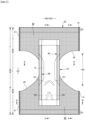
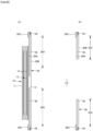
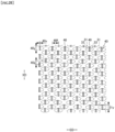
Fig. 1 is a plan view (internal surface side) of an underpants-type disposable diaper in a spread state. -
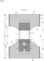
Fig. 2 is a plan view (external surface side) of the underpants-type disposable diaper in the spread state. -
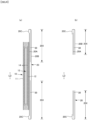
Fig. 3 is a plan view illustrating only a main part of the underpants-type disposable diaper in the spread state. -
Fig. 4(a) is a cross-sectional view taken along C-C line ofFig. 1 , andFig. 4(b) is a cross-sectional view taken along E-E line ofFig. 1 . -
Fig. 5 is a cross-sectional view taken along A-A line ofFig. 1 . -
Fig. 6 is a cross-sectional view taken along B-B line ofFig. 1 . -
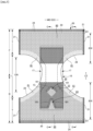
Fig. 7 is a plan view (external surface side) of an underpants-type disposable diaper in a spread state. -
Fig. 8(a) is a cross-sectional view taken along C-C line ofFig. 7 , andFig. 8(b) is a cross-sectional view taken along E-E line ofFig. 7 . -
Fig. 9(a) is a plan view of a main part of a stretchable region,Fig. 9(b) is a cross-sectional view taken along D-D line ofFig. 9(a), Fig. 9(c) is a cross-sectional view in a worn state, andFig. 9(d) is a cross-sectional view in a natural length state. -
Fig. 10 is a plan view illustrating various shapes of joined portions. -
Fig. 11 is a plan view of the stretchable region in the spread state. -
Fig. 12 is an enlarged plan view illustrating a main part of the stretchable region in the spread state. -
Fig. 13 is an enlarged plan view illustrating a main part of the stretchable region in the natural length state. -
Fig. 14(a) is a cross-sectional view taken along D-D line ofFig. 12 andFig. 14(b) is a cross-sectional view in the natural length state. -
Fig. 15 is a plan view of the stretchable region in the spread state. -
Fig. 16 is an enlarged plan view illustrating the main part of the stretchable region in the spread state. -
Fig. 17 is an enlarged plan view illustrating the main part of the stretchable region in the natural length state. -
Fig. 18 is a cross-sectional view schematically illustrating a cross section of a main part of an outer member stretched to some extent. -
Fig. 19 is a cross-sectional view schematically illustrating a cross section of a main part of an outer member stretched to some extent. -
Fig. 20(a) is a trace view of a plane photograph of a joined portion formed in a first welding mode, andFig. 20(b) is a trace view of a plane photograph of a joined portion formed in a third welding mode. -
Fig. 21 is a schematic view of an ultrasonic sealing device. -
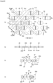
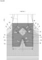
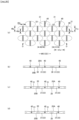
Fig. 22 is an enlarged plan view illustrating a main part of the stretchable region in the natural length state. -
Fig. 23 is an enlarged plan view illustrating the main part of the stretchable region in the spread state. -
Fig. 24 is a cross-sectional view schematically illustrating an elastic sheet stretchable structure. -
Fig. 25(a) is a plan view of a main part of a non-stretchable region,Fig. 25(b) is a cross-sectional view taken along D-D line ofFig. 25(a), Fig. 25(c) is a cross-sectional view in a worn state, andFig. 25(d) is a cross-sectional view in a natural length state. -
Fig. 26 is a plan view of the main part of the non-stretchable region. - Hereinafter, a detailed description will be given of an underpants-type disposable diaper as a typical example of an underpants-type disposable wearing article, referring to accompanying drawings. Incidentally, each of dotted pattern regions in the drawings indicates an adhesive as a bonding means that bonds respective components located on a top side and an underside thereof. The adhesive may be applied by solid, bead, curtain, summit, or spiral coating of a hot melt adhesive, or pattern coating (transfer of the hot melt adhesive in a letterpress method). Further, instead of or together with the above methods, the elastic member can be fixed by applying the hot melt adhesive to an outer peripheral surface of an elastic member by means of comb gun or sure wrap application or the like. Examples of the hot melt adhesive include EVA-based, pressure sensitive adhesion rubber-based (elastomer-based), polyolefin-based, and polyester/polyamide-based adhesives, and can be used without any particular limitation. As bonding means that bonds respective components, it is possible to use means by material welding such as heat sealing or ultrasonic sealing.
- Further, as a nonwoven fabric in the following description, a known nonwoven fabric can be appropriately used according to a site or a purpose. Examples of a constituent fiber of the nonwoven fabric include, but are not limited to, a synthetic fiber such as a polyolefin-based fiber including polyethylene and polypropylene, a polyester-based fiber, or a polyamide-based fiber (including a composite fiber such as core-sheath in addition to a single component fiber), a regenerated fiber such as rayon or cupra, and a natural fiber such as cotton. These fibers can be mixed and used. In order to enhance flexibility of the nonwoven fabric, it is preferable to use a crimped fiber as the constituent fiber. In addition, the constituent fiber of the nonwoven fabric may be a hydrophilic fiber (including a fiber that has become hydrophilic by a hydrophilizing agent), a hydrophobic fiber, or a water-repellent fiber (including a fiber that has become water-repellent by a water repellent agent). In addition, the nonwoven fabric is generally classified into a short fiber nonwoven fabric, a long fiber nonwoven fabric, a spunbond nonwoven fabric, a meltblown nonwoven fabric, a spunlace nonwoven fabric, a thermal bond (air-through) nonwoven fabric, a needle punch nonwoven fabric, a point bond nonwoven fabric, a laminated nonwoven fabric (an SMS nonwoven fabric, an SMMS nonwoven fabric, or the like in each of which different nonwoven fabric layers are laminated and a meltblown layer is sandwiched between spunbond layers, in addition to SSS nonwoven fabric in which same or similar nonwoven fabric layers are laminated), and the like depending on a fiber length, a sheet forming method, a fiber bonding method, and a stacked structure, and any of these nonwoven fabrics can be used. The laminated nonwoven fabric is manufactured as one unit including all layers integrally, and refers to a fabric processed by bonding fibers across the all layers. However, the laminated nonwoven fabric does not include a fabric formed by sticking, with a bonding means such as a hot melt adhesive, a plurality of nonwoven fabrics which have been manufactured separately.
-
Fig. 1 to Fig. 6 show an underpants-type disposable diaper including a front body part F covering a front side of a wearer and a back body part B covering a back side of the wearer. A reference character LD (longitudinal direction) denotes a front-back direction, and a reference character WD denotes a width direction. The underpants-type disposable diaper (hereinafter also simply referred to as a diaper) in the illustrated example includes anouter member 20 forming at least a lower torso region T and aninner member 10 fixed to theouter member 20, and theinner member 10 is provided with anabsorber 13 therein. In manufacturing, after an underside surface of theinner member 10 is bonded to an internal surface (upper surface) of theouter member 20 by bonding means such as a hotmelt adhesive, theinner member 10 and theouter member 20 are folded back at a center in the front-back direction LD (longitudinal direction) corresponding to a boundary between the front body part F and the back body part B, and both side portions thereof are bonded to each other by thermal welding or the hotmelt adhesive to formside seal portions 21, thereby obtaining the underpants-type disposable diaper in which a waist opening and a left-and-right-pair of leg opening portions are formed. - In particular, the back body part B in the illustrated example includes, as shown in enlarged view of
Fig. 22 , a pair of first portions B1, which face a left gluteal peak (top of a left gluteal swell) and a right gluteal peak (top of a right gluteal swell), respectively, and a second portion B2 located in that range of a center line passing through a center of the back body part in a width direction WD, which faces an intergluteal cleft. In addition, the back body part B includes also a third portion B3, which is a part of the center line passing through the center of the back body part in the width direction WD and located in a range facing a sacrum. - Positions of the first portion B1, the second portion B2 and the third portion B3 can be determined as appropriate according to dimensions, designs and the like of a product. As an example, in a spread state of the product from which the
side seal portions 21 are removed by cutting along edges thereof on a center side, respectively, assuming that a position of an edge of the waist opening of the front body part F corresponds to 0% and a position of an edge of the waist opening of the back body part B corresponds to 100%, the first portions B1 may be located in a range of 50 to 80%. In addition, in a spread state of the product (in a state in which the product is stretched to a maximum elongation in the width direction WD by pulling the product from both side ends thereof while one of theside seal portions 21 and the other of theside seal portions 21 are pinched, respectively), assuming that a side edge of one of theside seal portions 21 of the back body part B corresponds to 0% and a side edge of the other of theside seal portions 21 of the back body part B corresponds to 100%, one of the first portions B1 may be located in a range of 20 to 40% and the other of the first portions B1 may be located in a range of 60 to 80%, respectively. The positions of the first portions B1 in the width direction WD may be on both side edges of theabsorber 13, respectively. - In addition, in the spread state of the product from which the
side seal portions 21 are removed by cutting along the edges thereof on the center side, respectively, assuming that the position of the edge of the waist opening of the front body part F corresponds to 0% and the position of the edge of the waist opening of the back body part B corresponds to 100%, the second portion B2 may refer to a portion extending from a position in a range of 50 to 70% to a position in a range of 60 to 80%. Further, in the spread state of the product from which the side seal portions are removed by cutting along the edges thereof on the center side, respectively, assuming that the position of the edge of the waist opening of the front body part F corresponds to 0% and the position of the edge of the waist opening of the back body part B corresponds to 100%, the third portion B3 may refer to a portion extending from a position in a range of 60 to 80% to a position in a range of 70 to 90%. - As illustrated in
Fig. 4 to Fig. 6 , theinner member 10 has a structure in which theabsorber 13 is interposed between a liquid pervioustop sheet 11 and a liquidimpervious sheet 12 made of polyethylene, etc. and absorbs and holds excretion fluid passing through thetop sheet 11. A planar shape of theinner member 10 is not particularly limited. However, a substantially rectangular shape is generally adopted as shown inFig. 1 . - As the
top sheet 11 that covers a top side (skin contact side) of theabsorber 13, a perforated or non-perforated nonwoven fabric, a porous plastic sheet, etc. is preferably used. - As the liquid
impervious sheet 12 covering an underside (non-skin contact side) of theabsorber 13, a liquid impervious plastic sheet such as polyethylene or polypropylene may be used. In particular, a sheet having a moisture penetration property may be preferably used from a viewpoint of preventing stuffiness. Examples thereof include a microporous sheet obtained by melt-kneading an inorganic filler and a polyolefin resin such as polyethylene or polypropylene, molding the melt-kneaded mixture into a sheet, and then stretching the sheet in one or two axial directions. - As the
absorber 13, it is possible to use a known one, which is based on, for example, a pulp fiber stack, an assembly of filaments of cellulose acetate, etc., or a nonwoven fabric and which has superabsorbent polymer particles mixed therewith or fixed thereto, or the like as necessary. To hold the shape, to prevent the superabsorbent polymer particles from escaping from theabsorber 13, and for other purposes, theabsorber 13 can be wrapped in awrapping sheet 14 having a liquid pervious and liquid retaining property such as crepe paper as necessary. - The
absorber 13 is provided from the front body part F to the back body part B. In particular, it is preferable that theabsorber 13 extends backward beyond the pair of first portions B1, which face the left and right gluteal peaks, respectively, and both the side edges of the absorber extend, in the back body part B, so as to pass through positions, which are away from both line segments to outer sides thereof in the width direction WD, provided that the both line segments connect the first portions B1 and a front end of the second portion B2 (located in that range of the center line passing through the center of the back body part in the width direction WD,which faces the intergluteal cleft), respectively. In addition, it is preferable that theabsorber 13 extends backward beyond the front end of the third portion B3 facing the sacrum, and both the side edges of theabsorber 13 are away from both side edges of the third portion B3 to outer sides thereof in the width direction WD, respectively. - The
absorber 13 is preferably formed into a substantially hourglass shape having anarrower portion 13N narrower than both front and back sides at a crotch portion. However, it may have another shape such as a rectangular shape. A size of thenarrower portion 13N can be determined as appropriate. A length of thenarrower portion 13N in the front-back direction can be set to about 20 to 50% of a maximum length of the diaper, and a width of a narrowest portion thereof can be set to about 40 to 60% of amaximum width 13w of theabsorber 13. In the case of having such anarrower portion 13N, when the planar shape of theinner member 10 is substantially rectangular,non-absorber side portions 17 not having theabsorber 13 are formed at a portion corresponding to thenarrower portion 13N of theabsorber 13 in theinner member 10. - In the illustrated embodiment, the liquid
impervious sheet 12 is folded back to the underside together with thetop sheet 11 on both sides in the width direction WD of theabsorber 13. However, the liquidimpervious sheet 12 may extend beyond both the side edges of theabsorber 13 in the width direction or may extend between positions, which are away from both the side edges of theabsorber 13 to the center side thereof in the width direction, respectively. As this liquidimpervious sheet 12, it is desirable to use an opaque sheet so that brown color of excreta or urine is not seen. As opacification, a pigment or a filler such as calcium carbonate, titanium oxide, zinc oxide, white carbon, clay, talc, or barium sulfate added to plastic and formed into a film is preferably used. - It is preferable that three-dimensional gather
parts 90 fit around the legs are formed on both side portions of theinner member 10. As illustrated inFig. 5 andFig. 6 , each of the three-dimensional gatherparts 90 includes a fixedportion 91 fixed to a side portion of the underside surface of theinner member 10, amain unit section 92 extending from the fixedportion 91 up to a side portion of a top surface of theinner member 10 through a side of theinner member 10, a fallenportion 93 formed by front and back end portions of themain unit section 92 fixed to the side portion of the top surface of the inner member 10 (top sheet 11 in the illustrated example) in a fallen state using a hotmelt adhesive 95b, etc., and afree portion 94 formed between parts of the fallenportion 93 to be unfixed. Each of these portions is formed of a gathersheet 95 that is a duplicate sheet obtained by folding a sheet such as a nonwoven fabric. The gathersheet 95 is attached over the entireinner member 10 in the front-back direction, the fallenportion 93 is provided on the front side and the back side of each of thenon-absorber side portions 17, and thefree portion 94 extends to both the front and back sides of each of thenon-absorber side portions 17. In addition, between facing surfaces of the duplicate gathersheets 95, gatherelastic members 96 are disposed at tip portions and the like of the free portion. As illustrated inFig. 5 , the gatherelastic members 96 are for raising thefree portion 94 by an elastic contraction force in a product state. - A fixing structure of the gather
elastic members 96 and the gathersheet 95 is not particularly limited. For example, as in an example illustrated inFig. 5 andFig. 6 , it is possible to adopt a structure described in the following. In portions other than the fallenportion 93, the gatherelastic members 96 are attached and fixed to the gathersheet 95 through a hotmelt adhesive at positions of the gatherelastic members 96, and facing surfaces of the gathersheet 95 are bonded to each other. However, in the fallenportion 93, the hotmelt adhesive is not present at the positions of the gatherelastic members 96. Therefore, the gatherelastic members 96 and the gathersheet 95 are not attached to each other, and the facing surfaces of the gathersheet 95 are not bonded to each other at positions having the gatherelastic members 96. - As the gather
elastic member 96, it is possible to use a normally used material such as polystyrene-based rubber, polyolefin-based rubber, polyurethane-based rubber, polyester-based rubber, polyurethane, polyethylene, polystyrene, styrene-butadiene copolymer, silicone, polyester, etc. In addition, to make it difficult to see from the outside, it is preferable that a fineness is set to 925 dtex or less, a tension is set to 150 to 350%, and an interval is set to 7.0 mm or less. Incidentally, as the gatherelastic member 96, it is possible to use a tape-like member having a certain width in addition to an elongated member as in the illustrated example. - As a material of the gather
sheet 95, various kinds of nonwoven fabrics may be used. However, in particular, in order to prevent stuffiness, it is preferable to use a nonwoven fabric that suppresses a basis weight and has excellent air permeability. Further, with regard to the gathersheet 95, to prevent passage of urine, etc., prevent a rash, and enhance a feel to a skin (dry feeling), it is preferable to use a water repellent nonwoven fabric coated with a silicone-based, paraffin metal-based, or alkylchromic chloride-based water repellent agent, etc. - As illustrated in
Fig. 3 to Fig. 6 , the underside surface of theinner member 10 is bonded to the internal surface of theouter member 20 by a hotmelt adhesive, etc. in an innermember fixing region 10B (shaded region). The range of the innermember fixing region 10B can be determined as appropriate and may cover almost the entireinner member 10. However, it is preferable that both ends of theinner member 10 in the width direction are not fixed to theouter member 20. - The
outer member 20 forms at least the lower torso region T of the front body part F and the lower torso region T of the back body part B. In the illustrated example, theouter member 20 further includes an intermediate region L corresponding to a range in the front-back direction between the lower torso region T of the front body part F and the lower torso region T of the back body part B. However, at least one of the front body part F and the back body part B may not include the intermediate region L. Referring to theouter member 20, as in the illustrated example, in the crotch portion, side edges of theouter member 20 may be located on a central side with respect to side edges of theinner member 10 in the width direction or located on an outer side thereof in the width direction. - A part located on the lower torso region T in the
outer member 20 can be divided into awaist end portion 23 forming an end portion on a waist opening side and an under-waist portion U which is a portion lower than thewaist end portion 23. When theouter member 20 has, in the part located on the lower torso region T, boundaries in each of which a stretching force in the width direction WD changes (boundaries in each of which e.g., the type, fineness, thickness, or stretch rate of the elastic member changes), a portion on the waist opening side of a boundary closest to the waist opening refers to thewaist end portion 23. When there is no such a boundary, a portion extending from theabsorber 13 or the inner member 19 on the waist opening side refers to thewaist end portion 23. The lengths of these portions in the front-back direction LD can be determined as appropriate according to the size, type, etc. of the product. - In order to improve fitting to a body, in the
outer member 20, astretchable region 80, which is elastically stretching and contracting together with elastic members, may be formed by attaching the elastic members to appropriate sites. In a natural length state, thestretchable region 80 is contracted according to contraction of the elastic members such that wrinkles or pleats are formed. Then, thestretchable region 80 may be stretched together with the elastic members to a predetermined maximum elongation so as to be spread without forming wrinkles. As the elastic member, a known elongated elastic member such as a thread shaped elastic member and a belt shaped elastic member may be used. In addition to these members, it is also possible without any particular limitation to use anelastic sheet 30 such as elastic film and a nonwoven fabric made of elastomeric fibers. It is preferable that a plurality ofstretchable regions 80 is provided at individual sites located in thewaist end portion 23, the under-waist portion U and the intermediate region L. However, as can be known from anon-stretchable region 70 discussed below, thestretchable region 80 may be partially omitted at a middle portion thereof in the width direction WD, a middle portion thereof in the front-back direction LD, etc. - In the
outer member 20 of the illustrated example, except for a part located in a portion of the intermediate region L, as illustrated inFig. 2 andFig. 4 toFig. 6 , theelastic sheet 30 is interposed between afirst sheet layer 20A and asecond sheet layer 20B, and as illustrated inFig. 9 , theouter member 20 has an elastic sheetstretchable structure 20X in which thefirst sheet layer 20A and thesecond sheet layer 20B are bonded throughjoint holes 31 penetrating theelastic sheet 30 at a large number of joinedportions 40 arranged at intervals. Further, a region having this elastic sheetstretchable structure 20X includes thestretchable region 80 that contracts in the width direction by contraction of theelastic sheet 30 and is extensible in the width direction (that is, the stretchable direction ED is the width direction WD of the diaper). - A planar shape of the
outer member 20 is formed by concave around-leg lines 29 so that both side edges of the intermediate region L in the width direction form leg openings, respectively, and has a shape similar to an hourglass as a whole. Theouter member 20 may be formed separately in the front body part F and the back body part B, and both bodies may be disposed to be separated in the front-back direction LD of the diaper at the crotch portion. - An embodiment illustrated in
Fig. 1 andFig. 2 is an embodiment in which the elastic sheetstretchable structure 20X extends to thewaist end portion 23. However, the elastic sheetstretchable structure 20X used for thewaist end portion 23 may cause insufficient tightening to thewaist end portion 23. Therefore, as illustrated inFig. 7 andFig. 8 , in thewaist end portion 23, the elastic sheetstretchable structure 20X is not provided, and a stretchable structure by conventional elongated waist end portionelastic members 24 can be provided as necessary. The waist end portionelastic members 24 are elongated elastic members such as a plurality of rubber threads arranged at intervals in the front-back direction LD, and the waist end portionelastic members 24 apply a stretching force to tighten a waist circumference of the body. The waist end portionelastic members 24 are not disposed substantially in a bundle at close intervals, and three or more waist end portionelastic members 24, preferably five or more waist end portionelastic members 24 are disposed at intervals of about 3 to 8 mm in the front-back direction to form a predetermined stretchable zone. A stretch rate of the waist end portionelastic members 24 at the time of fixing can be determined as appropriate, and may be set to about 230 to 320% for a normal adult. As the waist end portionelastic members 24, rubber threads are used in the illustrated example. However, other elongated elastic members such as flat rubber may be used. Although not illustrated, theelastic sheet 30 may be provided at thewaist end portion 23, and the elongated waist end portionelastic members 24 may be provided at positions overlapping theelastic sheet 30, so that a stretchable structure using both elastic members can be provided. In addition, in the illustrated embodiment, the elongated elastic members extending along leg openings are not provided in the edge portions of the leg openings in theouter member 20, but the elongated elastic members may be provided at positions overlapping theelastic sheet 30 in the edge portions or instead of theelastic sheet 30 of the edge portions. - As other embodiments, although not illustrated, appropriate modifications can be made. For example, the elastic sheet
stretchable structure 20X may not be provided in the intermediate region L, the elastic sheetstretchable structure 20X may be continuously provided in the front-back direction LD from the inside of the lower torso region T of the front body part F to the inside of the lower torso region T of the back body part B via the intermediate region L, or the elastic sheetstretchable structure 20X may be provided only in one of the front body part F and the back body part B. - A region having the elastic sheet
stretchable structure 20X in theouter member 20 has thestretchable region 80 that can be stretched and contracted in the width direction WD. Thestretchable region 80 contracts in the width direction WD by a contraction force of theelastic sheet 30 and is extensible in the width direction WD. More specifically, in a state where theelastic sheet 30 is stretched in the width direction WD, thefirst sheet layer 20A and thesecond sheet layer 20B are bonded through thejoint holes 31 of theelastic sheet 30 at intervals in each of the width direction WD and the front-back direction LD orthogonal thereto (the direction LD orthogonal to the stretchable direction ED) to form a large number of the joinedportions 40, thereby forming the elastic sheetstretchable structure 20X. Further, in thestretchable region 80, theelastic sheet 30 is left without disconnection in the width direction WD, and the joinedportions 40 are disposed such that thefirst sheet layer 20A and thesecond sheet layer 20B contract by the contraction force of theelastic sheet 30 and contraction pleats 25 are formed, thereby imparting such elasticity. - The
stretchable region 80 may haveportions 32 in each of which theelastic sheet 30 is linearly continuous along the width direction WD as in an example illustrated inFig. 9 or may not havesuch portions 32 as in an example illustrated inFig. 11 and an example illustrated inFig. 15 . - In the
stretchable region 80, thefirst sheet layer 20A and thesecond sheet layer 20B between the joinedportions 40 swell in a direction in which they are separated from each other, thereby forming the contraction pleats 25 extending in the front-back direction LD in the natural length state as illustrated inFig. 9 , andFig. 14(b) . Further, in the worn state of being stretched to some extent in the width direction WD, the contraction pleats 25 are left even though the contraction pleats 25 are extended. In addition, as in the illustrated embodiment, since thefirst sheet layer 20A and thesecond sheet layer 20B are not bonded to theelastic sheet 30 at least in a portion other than between thefirst sheet layer 20A and thesecond sheet layer 20B in the joinedportions 40, as can be seen fromFig. 9(c) assuming a worn state andFig. 9(a) assuming a spread state of thefirst sheet layer 20A and thesecond sheet layer 20B, in these states, edges of thejoint holes 31 in theelastic sheet 30 are separated from outer peripheral edges of the joinedportions 40 in the stretchable direction ED, respectively, so that vent holes 33 (gaps) are formed so as to open. Thus, even when the material of theelastic sheet 30 is a non-porous film or sheet, air permeability is imparted by the vent holes 33. In particular, in the case where theelastic sheet 30 has theportions 32 linearly continuous along the width direction WD, thejoint holes 31 narrow due to further contraction of theelastic sheet 30 and a gap is hardly formed between thejoint holes 31 and the joinedportions 40 in the natural length state. On the other hand, in the case where theelastic sheet 30 does not have the portions linearly continuous along the width direction WD, the vent holes 33 are left. - It is desirable that a maximum elongation in the width direction WD of the
stretchable region 80 is 190% or more (preferably 200 to 220%). Basically, the maximum elongation of thestretchable region 80 is substantially determined by the stretch rate of theelastic sheet 30 at the time of manufacture. However, the maximum elongation decreases due to factors that inhibit contraction in the width direction WD based thereon. A main factor of such inhibition is a ratio of the length L of the joinedportions 40 per unit length in the width direction WD, and the maximum elongation decreases as this ratio increases. In a normal case, since the length L of the joinedportions 40 has a correlation with an area ratio of the joinedportions 40, the maximum elongation of thestretchable region 80 can be adjusted by the area ratio of the joinedportions 40. - As in the examples illustrated in
Fig. 9 , in the case where theelastic sheet 30 has theportions 32 linearly continuous along the width direction WD, the stretching stress of thestretchable region 80 can be adjusted mainly by a sum ofdimensions 32w orthogonal to the width direction WD (equal tointervals 31d of the joint holes 31) of theportions 32 in each of which theelastic sheet 30 is linearly continuous along the width direction WD (seeFig. 9(a) ). On the other hand, as in the example illustrated inFig. 11 and the example illustrated inFig. 15 , in the case where theelastic sheet 30 does not have the portions linearly continuous along the width direction WD, the stretching stress of thestretchable region 80 can be adjusted by an intersecting angle Θ1 between the stretchable direction ED and the continuous direction ofnon-joint band 51, and an intersecting angle Θ2 between the stretchable direction ED and the continuous direction ofnon-joint band 52. Here, in each of thenon-joint bands portions 40 is continuous. In a normal case, it is preferable that the acute intersecting angle Θ1 between the stretchable direction ED and the continuous direction of thenon-joint band 51, and the acute intersecting angle Θ2 between the stretchable direction ED and the continuous direction of thenon-joint band 52, in the spread state, are set to be more than 0 degrees and 45 degrees or less, particularly a range of 10 to 30 degrees. - The area ratio of the joined
portions 40 and the area of each of the joinedportions 40 in thestretchable region 80 can be determined as appropriate and are preferably within the following ranges in a normal case. - Area of each of the joined portions 40: 0.14 to 3.5 mm2 (particularly 0.14 to 1.0 mm2)
- Area ratio of the joined portions 40: 1.8 to 19.1% (particularly 1.8 to 10.6%)
- As described above, the maximum elongation and stretching stress of the
stretchable region 80 can be adjusted by the area of each of the joinedportions 40. Thus, as illustrated inFig. 7 , a plurality of regions having different area ratios of the joinedportions 40 may be provided in thestretchable region 80 to change fitting according to the site. In the embodiment illustrated inFig. 7 ,edge portion regions 81 of leg openings correspond to a flexibly stretching and contracting region in which the area ratio of the joinedportions 40 is high comparing to other regions in thestretchable region 80, and thus the stretching stress is weak. - A shape of each of the joined
portions 40 and a shape of each of thejoint holes 31 in the natural length state can be determined as appropriate, and may be set to any shape such as a perfect circle, an ellipse, a polygon such as a triangle, a rectangle (seeFig. 9 ,Fig. 11 andFig. 15 ), or a rhombus (seeFig. 10(b) ), a convex lens shape (seeFig. 10(a) ), a concave lens shape (seeFig. 10(c) ), a star shape, a cloud shape, etc. The dimensions of the individual joinedportions 40 are not particularly limited. However, amaximum length 40y (approximately equal to adimension 31y of each of thejoint holes 31 in the orthogonal direction to the stretchable direction) is preferably 0.5 to 3.0 mm, particularly preferably 0.7 to 1.1 mm, and amaximum width 40x is preferably 0.1 to 3.0 mm, particularly 0.1 to 1.1 mm in the case of a shape that is long in a direction XD orthogonal to the stretchable direction ED. - An arrangement pattern of the joined
portions 40 in thestretchable region 80 is not particularly limited and any pattern (see for example,Patent Literatures 1 to 8) can be adopted. In particular, as in the example illustrated inFig. 9 , as in the example illustrated inFig. 11 , and as in the example illustrated inFig. 15 , it is preferable that thenon-joint bands portions 40 is continuous are formed in an oblique lattice shape. The examples illustrated in the drawings are particularly preferable. That is, in each of these examples, in thestretchable region 80, as thenon-joint bands portions 40 is continuous, in the spread state, a firstnon-joint band 51 linearly continuous along afirst direction 51d intersecting the stretchable direction ED at an acute angle (the acute intersecting angle Θ1) is repeatedly present at intervals in a direction orthogonal to thefirst direction 51d. In addition, a large number of the joinedportions 40 andjoint holes 31 are provided at intervals between adjacent firstnon-joint bands 51 in thestretchable region 80. Further, characteristically, a unit structure including a plurality of firstnon-joint bands 51 having differentfirst widths 51w determined as widths in the direction orthogonal to thefirst direction 51d is repeatedly present in the direction orthogonal to thefirst direction 51d in thestretchable region 80. - As described above, when the unit structure including the plurality of first
non-joint bands 51 having differentfirst widths 51w is repeatedly present in the direction orthogonal to thefirst direction 51d in thestretchable region 80, a similar magnitude change in width is formed in continuous portion of theelastic sheet 30 inside the firstnon-joint bands 51. That is, when thewidth 51w of the firstnon-joint bands 51 is narrow, the width of the continuous portion of theelastic sheet 30 on the inside is narrowed. In addition, when thewidth 51w of the firstnon-joint bands 51 is wide, the width of the continuous portion of theelastic sheet 30 on the inside is widened. Further, when there is a change in thefirst width 51w in the continuous portion of theelastic sheet 30 in the firstnon-joint bands 51, both the continuous portion of theelastic sheet 30 in the firstnon-joint band 51 having a wide width and the continuous portion of theelastic sheet 30 in the firstnon-joint bands 51 having a narrow width are visually emphasized. As a result, regardless of whether thestretchable region 80 is in the natural length state (seeFig. 13 andFig. 17 ) or in the worn state stretched to some extent, an appearance having beautiful oblique stripe patterns is exhibited. That is, in a state of being contracted to some extent, a size of the contraction pleats 25 in the firstnon-joint bands 51 changes according to thefirst width 51w of the firstnon-joint band 51, and thus an oblique stripe pattern appears more clearly due to an influence of the contraction pleats 25. - The unit structure described above is not limited by the magnitude of the
width 51w as long as the plurality of firstnon-joint bands 51 having differentfirst widths 51w is included. However, it is preferable that a largefirst width 51w in the firstnon-joint bands 51 is 1.2 to 60 times that of a firstnon-joint band 51 having aclosest width 51w and a smallfirst width 51w is 0.01 to 0.8 times that of the firstnon-joint band 51 having theclosest width 51w. - In addition, in the unit structure described above, as long as the plurality of first
non-joint bands 51 having the differentfirst widths 51w is included, thefirst widths 51w in all the firstnon-joint bands 51 may be different from each other, and afirst width 51w in some of the plurality of firstnon-joint bands 51 may be different from afirst width 51w of one or a plurality of other firstnon-joint bands 51 as illustrated in the figure. - Even if an oblique stripe pattern along the
first direction 51d due to the contraction pleats 25 of the firstnon-joint bands 51 and the continuous portion of theelastic sheet 30 therein appears in thestretchable region 80, when an oblique stripe pattern along another oblique direction is more strongly visually recognized in the samestretchable region 80, there is concern that the oblique stripe pattern due to the contraction pleats 25 of the firstnon-joint bands 51 and the continuous portion of theelastic sheet 30 therein becomes inconspicuous. On the other hand, it is preferable that a maximum value of thefirst widths 51w in the firstnon-joint bands 51 is a maximum value of widths in a direction orthogonal to a continuous direction in all thenon-joint bands non-joint bands 51 and the continuous portion of theelastic sheet 30 therein is more strongly visually recognized in thestretchable region 80. In this case, the maximum value of thefirst widths 51w in the firstnon-joint bands 51 can be determined as appropriate, and is preferably 1.2 to 60 times that of the firstnon-joint band 51 having theclosest width 51w. Incidentally, widths of all thenon-joint bands non-joint bands 51 in the direction orthogonal to the continuous direction are not limited and are preferably within a range of 0.02 to 5 mm in a normal case. Naturally, with regard to the widths of thenon-joint bands non-joint bands 51 in the direction orthogonal to the continuous direction thereof correspond to thefirst widths 51w, and each of these width has a constant value, because thesenon-joint bands - A
first interval 51s determined as an interval between the adjacent firstnon-joint bands 51 in the direction orthogonal to thefirst direction 51d can be determined as appropriate. Therefore, thefirst interval 51s may be the same as, wider than, or narrower than thefirst width 51w of the adjacent firstnon-joint bands 51. As one preferable example, it is possible to mention a mode in which the maximum value of thefirst widths 51w of the firstnon-joint bands 51 is smaller than a maximum value of thefirst interval 51s in the unit structure. In this way, by forming a wide interval portion in the unit structure, the oblique stripe pattern due to the contraction pleats 25 of the firstnon-joint bands 51 and the continuous portion of theelastic sheet 30 therein is more strongly visually recognized. In this case, the maximum value of thefirst widths 51w of the firstnon-joint bands 51 can be determined as appropriate, and is preferably 0.01 to 9 times the maximum value of thefirst interval 51s. Incidentally, intervals between all thenon-joint bands non-joint bands 51 in the direction orthogonal to the continuous direction are not particularly limited and are preferably within a range of 0.3 to 50 mm in a normal case. Naturally, with regard to the intervals between the adjacentnon-joint bands 51 and between the adjacentnon-joint bands 52, for example, the intervals between the adjacent firstnon-joint bands 51 in the direction orthogonal to the continuous direction thereof correspond to thefirst intervals 51s, and each of these intervals has a constant value along the continuous direction. - In the
stretchable region 80, with regard tonon-joint bands non-joint bands 52 linearly continuous along asecond direction 52d intersecting the stretchable direction ED at an acute angle (acute intersecting angle Θ2) other than thefirst direction 51d may be repeatedly present at intervals in a direction orthogonal to thesecond direction 52d, or the secondnon-joint bands 52 may not be present. In one preferable mode having the secondnon-joint bands 52, thenon-joint bands stretchable region 80, the firstnon-joint bands 51 are continuous portions in one direction in thenon-joint bands non-joint bands 52 are continuous portions in another direction in thenon-joint bands first direction 51d and thesecond direction 52d are opposite to each other in terms of inclination with respect to the stretchable direction ED. Incidentally, as in the example illustrated inFig. 11 and the example illustrated inFig. 15 , even in a mode not having thenon-joint bands second directions stretchable region 80, elasticity in thestretchable region 80 can be sufficiently ensured. - However, when an oblique stripe pattern along an oblique direction of the second
non-joint bands 52 is more strongly visually recognized in the samestretchable region 80, there is concern that the oblique stripe pattern due to the contraction pleats 25 of the firstnon-joint bands 51 and the continuous portion of theelastic sheet 30 therein becomes inconspicuous. Therefore, in the case where the secondnon-joint bands 52 are present as in the example illustrated inFig. 15 , it is desirable that all thesecond widths 52w determined as a width in the direction orthogonal to thesecond direction 52d in the secondnon-joint bands 52 are the same, or the joinedportions 40 are disposed so that the secondnon-joint bands 52 are not present. In this way, in thestretchable region 80, the oblique stripe pattern due to the contraction pleats 25 of the firstnon-joint bands 51 and the continuous portion of theelastic sheet 30 inside thereof is more strongly visually recognized. - Meanwhile, between adjacent first
non-joint bands 51, the joinedportions 40 are aligned in thefirst direction 51d. In this case, for example, as illustrated inFig. 16 , it is preferable that all the joinedportions 40 have an elongated shape in which an acute intersecting angle θ3 between the longitudinal direction and the direction orthogonal to the stretchable direction ED is within 10 degrees and amaximum dimension 40e in the stretchable direction ED is 0.1 to 0.4 mm since it is possible to ensure a larger dimension of the firstnon-joint bands 51 in the stretchable direction ED and to suppress a decrease in elasticity. - In addition, as in the example illustrated in
Fig. 11 , when the unit structure includes a plurality of first widenon-joint bands 51 having a maximumfirst width 51w and a plurality of first narrownon-joint bands 51 having a narrowerfirst width 51w adjacent to each other in the direction orthogonal to thefirst direction 51d, it is preferable that each of the joinedportions 40 having an elongated shape in which the acute intersecting angle between the longitudinal direction and thesecond direction 52d is within 5 degrees and amaximum dimension 40f in the direction orthogonal to the longitudinal direction is 0.1 to 0.4 mm are aligned at intervals in thefirst direction 51d between the adjacent first widenon-joint bands 51. In addition, it is preferable that each of the joinedportions 40 having an elongated shape in which the acute intersecting angle θ3 between the longitudinal direction and thefirst direction 51d is 45 degrees or more and amaximum dimension 40g in the direction orthogonal to the longitudinal direction is 0.1 to 0.4 mm are aligned at intervals in thefirst direction 51d between the adjacent first narrownon-joint bands 51. By such a shape and arrangement of the joinedportions 40, the contraction pleats 25 of the firstnon-joint bands 51 and the continuous portion of theelastic sheet 30 therein are particularly visually emphasized due to the smaller area of each of the joinedportions 40. - One row or a plurality of rows of the joined portions 40 (rows in the continuous direction of the
non-joint bands 51 and 52) may be located between the adjacentnon-joint bands portions 40 in a row direction are regular. However, all the intervals may not be constant, and some intervals may be different. - In a region having the elastic sheet
stretchable structure 20X in theouter member 20, as illustrated inFig. 7 , thenon-stretchable region 70 may be provided at least on one side of thestretchable region 80 in the width direction. Thenon-stretchable region 70 means that a maximum elongation in the stretchable direction ED is 120% or less. The maximum elongation of thenon-stretchable region 70 is preferably 110% or less, and more preferably 100%. Arrangement of thestretchable region 80 and thenon-stretchable region 70 can be determined as appropriate. In the case of theouter member 20 of the underpants-type disposable diaper as in the present example, a portion overlapping theabsorber 13 is a region not requiring high elasticity. Thus, as in the illustrated embodiment, it is preferable to form a part or all of the portion overlapping the absorber 13 (it is desirable to include almost the entire innermember fixing region 10B) into thenon-stretchable region 70. Naturally, thenon-stretchable region 70 may be provided from a region overlapping theabsorber 13 to a region not overlapping theabsorber 13 away from the region in the width direction WD or the front-back direction LD, and thenon-stretchable region 70 may be provided only in the region not overlapping theabsorber 13. - The shape of each of the joined
portions 40 in thenon-stretchable region 70 is not particularly limited, and may be appropriately selected from the same shapes as those described in the section of thestretchable region 80. - In addition, the area ratio of the joined
portions 40 and the area of each of the joinedportions 40 in thenon-stretchable region 70 can be determined as appropriate. However, in a normal case, the area ratio and the area are preferably within the following ranges since thenon-stretchable region 70 does not become hard due to the small area of each of the joinedportions 40 and the low area ratio of the joinedportions 40. - Area of each of the joined portions 40: 0.10 to 0.75 mm2 (particularly 0.10 to 0.35 mm2)
- Area ratio of the joined portions 40: 4 to 13% (particularly 5 to 10%)
- The
non-stretchable region 70 can be formed by densely disposing the joinedportions 40 so that thefirst sheet layer 20A and thesecond sheet layer 20B are prevented from being contracted by the contraction force of theelastic sheet 30 to form pleats. Specific examples of a method for forming thenon-stretchable region 70 include those shown in, for example, Patent Literatures 3 to 6.Fig. 25 andFig. 26 illustrate an example of thenon-stretchable region 70 disclosed in Patent Literature 6. Although theelastic sheet 30 has been originally continuous along the stretchable direction ED, in thisnon-stretchable region 70, thejoint holes 31 are arranged densely at least to a certain degree in a staggered shape such that theelastic sheet 30 does not, due to the presence of thesejoint holes 31, have the portions linearly continuous along the stretchable direction ED. In this case, as shown inFig. 25 andFig. 26 , in both the natural length state and the spread state, the vent holes (gaps) 33 are formed so as to open with a substantially the same size. - When the
first sheet layer 20A and thesecond sheet layer 20B are bonded in the joinedportions 40 through thejoint holes 31 formed in theelastic sheet 30, it is desirable that neither thefirst sheet layer 20A nor thesecond sheet layer 20B is bonded to theelastic sheet 30 except at least between thefirst sheet layer 20A and thesecond sheet layer 20B in the joinedportions 40. - Means for bonding the
first sheet layer 20A and thesecond sheet layer 20B in the joinedportions 40 is not particularly limited. For example, in the joinedportions 40, thefirst sheet layer 20A and thesecond sheet layer 20B may be bonded with a hot melt adhesive or may be bonded by means of material welding such as heat sealing or ultrasonic sealing. - In a case in which the
first sheet layer 20A and thesecond sheet layer 20B are bonded through thejoint holes 31 of theelastic sheet 30 in the joinedportions 40, as a mode in which the joinedportions 40 are formed by material welding, it is possible to adopt any one of a first welding mode, a second welding mode and a third welding mode, as follows. In the first welding mode, thefirst sheet layer 20A and thesecond sheet layer 20B are bonded only by a molten and solidified material 20m of a most part or a part of at least one of thefirst sheet layer 20A and thesecond sheet layer 20B in the joined portions 40 (seeFig. 18(a) ). In the second welding mode, thefirst sheet layer 20A and thesecond sheet layer 20B are bonded only by a molten and solidified material 30m of all, a most part, or a part of theelastic sheet 30 in the joined portions 40 (seeFig. 18(b) ). In the third welding mode, both of these modes are combined (seeFig. 18(c) ). Among these modes, the second and third welding modes are preferable. - A particularly preferable mode is that the
first sheet layer 20A and thesecond sheet layer 20B are bonded by the molten and solidified material 20m of the part of thefirst sheet layer 20A and thesecond sheet layer 20B and a molten and solidified material 30m of all or the most part of theelastic sheet 30 in the joinedportions 40. Incidentally, in the third welding mode illustrated inFig. 20(b) , the molten and solidified material 30m of theelastic sheet 30 shown in white is seen among the molten and solidified material 20m of fibers in thefirst sheet layer 20A or thesecond sheet layer 20B shown in black. On the other hand, in the first welding mode illustrated inFig. 20(a) , the molten and solidified material 30m of theelastic sheet 30 is not seen among the molten and solidified material 20m of the fibers in thefirst sheet layer 20A or thesecond sheet layer 20B. - When the
first sheet layer 20A and thesecond sheet layer 20B are bonded using the molten and solidified material 20m of the most part or the part of at least one of thefirst sheet layer 20A and thesecond sheet layer 20B as an adhesive as in the first welding mode or the third welding mode, it is preferable that a part of thefirst sheet layer 20A and thesecond sheet layer 20B is not melted since the joinedportions 40 are not hardened. - Incidentally, when the
first sheet layer 20A and thesecond sheet layer 20B are nonwoven fabrics, a case in which a part of thefirst sheet layer 20A and thesecond sheet layer 20B does not melt includes a mode in which cores (not only cores in composite fibers, but also central parts in single component fivers) of all fibers do not melt but surrounding parts thereof (not only sheath in composite fibers, but also surrounding parts in single component fivers) melt, or a mode in which some fibers do not melt at all while remaining fibers totally melt or while cores of the remaining fibers are left but surrounding parts thereof melt. - When the
first sheet layer 20A and thesecond sheet layer 20B are bonded using the molten and solidified material 30m of theelastic sheet 30 as an adhesive like the second welding mode and the third welding mode, the peel strength becomes high. In the second welding mode, under a condition that a melting point of at least one of thefirst sheet layer 20A and thesecond sheet layer 20B is higher than a melting point of theelastic sheet 30 and a heating temperature at the time of forming the joinedportions 40, theelastic sheet 30 is sandwiched between thefirst sheet layer 20A and thesecond sheet layer 20B, and portions to be the joinedportions 40 are pressurized and heated such that only theelastic sheet 30 is melted at the time of manufacture. - On the other hand, in the third welding mode, under a condition that a melting point of at least one of the
first sheet layer 20A and thesecond sheet layer 20B is higher than the melting point of theelastic sheet 30, theelastic sheet 30 is sandwiched between thefirst sheet layer 20A and thesecond sheet layer 20B, and portions to be the joinedportions 40 are pressurized and heated such that at least one of thefirst sheet layer 20A and thesecond sheet layer 20B and theelastic sheet 30 are melted at the time of manufacture. - From such a viewpoint, the melting point of the
elastic sheet 30 is preferably about 80 to 145°C, and the melting point of thefirst sheet layer 20A and thesecond sheet layer 20B is preferably about 85 to 190°C, particularly preferably 150 to 190°C. The difference between the melting points of thefirst sheet layer 20A and thesecond sheet layer 20B and the melting point of theelastic sheet 30 is preferably about 60 to 90°C. The heating temperature is preferably about 100 to 150°C. - In the second welding mode and the third welding mode, when the
first sheet layer 20A and thesecond sheet layer 20B are nonwoven fabrics, the molten and solidified material 30m of theelastic sheet 30 may penetrate between fibers over the entirefirst sheet layer 20A andsecond sheet layer 20B in a thickness direction in the joinedportions 40 as illustrated inFig. 19(c) . However, in a mode in which the molten and solidifiedmaterial 30m penetrates between the fibers to the middle in the thickness direction as illustrated inFig. 19(a) , or a mode in which the molten and solidifiedmaterial 30m hardly penetrates between the fibers of thefirst sheet layer 20A and thesecond sheet layer 20B as illustrated inFig. 19(b) , flexibility of the joinedportions 40 becomes high. -
Fig. 21 illustrates an example of an ultrasonic sealing device suitable for forming the second welding mode and the third welding mode. In this ultrasonic sealing device, when the joinedportions 40 are formed, thefirst sheet layer 20A, theelastic sheet 30, and thesecond sheet layer 20B are fed between ananvil roll 60 havingprojections 60a formed in the pattern of the joinedportions 40 on an outer surface and anultrasonic horn 61. At this time, for example, by setting a feeding speed of theelastic sheet 30 on an upstream side by afeed drive roll 63 and anip roll 62 to be lower than a feeding speed on a downstream side of theanvil roll 60 and theultrasonic horn 61, theelastic sheet 30 is stretched to a predetermined stretch rate in an MD (machine direction, flow direction) through a path from a nip position by thefeed drive roll 63 and thenip roll 62 to a seal position by theanvil roll 60 and theultrasonic horn 61. The stretch rate of theelastic sheet 30 can be set by selecting a speed difference between theanvil roll 60 and thefeed drive roll 63, and can be set to about 300% to 500%, for example. - The
first sheet layer 20A, theelastic sheet 30, and thesecond sheet layer 20B fed between theanvil roll 60 and theultrasonic horn 61 are heated by ultrasonic vibration energy of theultrasonic horn 61 while being pressurized between theprojections 60a and theultrasonic horn 61 in a state of being stacked in this order. By melting only theelastic sheet 30 or melting at least one of thefirst sheet layer 20A and thesecond sheet layer 20B and theelastic sheet 30, thejoint holes 31 are formed in theelastic sheet 30. At the same time, thefirst sheet layer 20A and thesecond sheet layer 20B are bonded through the joint holes 31. Therefore, in this case, by selecting a size, a shape, a separation interval, and an arrangement pattern in a roll length direction and a roll circumferential direction of theprojections 60a of theanvil roll 60, it is possible to select an area ratio of the joinedportions 40. - A reason why the
joint holes 31 are formed may not be clear. However, it is considered that the holes are formed when portions corresponding to theprojections 60a of theanvil roll 60 in theelastic sheet 30 are melted and detached from the surroundings. In this instance, as illustrated inFig. 9(a) ,Fig. 12 andFig. 13 , in theelastic sheet 30, a portion, which is disposed between adjacentjoint holes 31 aligned in the stretchable direction ED, is cut from portions on both sides in the stretchable direction ED by thejoint holes 31, and loses support on both sides in a contracting direction. Thus, in a range in which continuity in a direction orthogonal to the contracting direction is secured, the portion, which is disposed between adjacentjoint holes 31 aligned in the stretchable direction ED, contracts more, with increasing proximity to a center side in the direction LD orthogonal to the stretchable direction ED, until this center side in the direction LD balances with a center side in the stretchable direction ED, and thejoint holes 31 expand in the stretchable direction ED. - Although a constituent material of the
first sheet layer 20A and thesecond sheet layer 20B is not particularly limited, it is preferable for the material to have air permeability. From the viewpoints, a nonwoven fabric may be preferably used. When the nonwoven fabric is used, the basis weight thereof is preferably about 10 to 25 g/m2. Further, a part or the whole of thefirst sheet layer 20A and thesecond sheet layer 20B may be a pair of layers in which a single material is folded back to face each other. For example, as in the illustrated embodiment, in thewaist end portion 23, the constituent material located on the outer side is regarded as thesecond sheet layer 20B, and the foldedportion 20C folded back to the internal surface side at a waist opening edge is regarded as thefirst sheet layer 20A, and anelastic sheet 30 is interposed therebetween. In the other portions, the constituent material located on the inner side is regarded as thefirst sheet layer 20A, the constituent material located on the outer side is regarded as thesecond sheet layer 20B, and theelastic sheet 30 can be interposed therebetween. It is obvious that the constituent material of thefirst sheet layer 20A and the constituent material of thesecond sheet layer 20B can be individually provided over the entire front-back direction LD, and without folding back the constituent materials, theelastic sheet 30 may be interposed between the constituent material of thefirst sheet layer 20A and the constituent material of thesecond sheet layer 20B. - The
elastic sheet 30 is not particularly limited. As long as it is made of a thermoplastic resin which has elasticity, it may be an elastic nonwoven fabric in addition to elastic film. Further, as theelastic sheet 30, in addition to an imperforate sheet, those having many holes and slits for ventilation can also be used. In particular, in theelastic sheet 30, the tensile strength in the width direction WD (stretchable direction ED, MD direction) is preferably 8 to 25 N/35 mm, the tensile strength in the front-back direction LD (direction XD orthogonal to the stretchable direction ED, CD direction) is preferably 5 to 20 N/35 mm, the tensile elongation in the width direction WD is preferably 450 to 1050%, and the tensile elongation in the front-back direction LD is preferably 450 to 1400%. The thickness of theelastic sheet 30 is not particularly limited, but it is preferably about 20 to 40 µm. - Unlike the present example, in the
outer member 20, a part or whole of thestretchable region 80, thenon-stretchable region 70 as well as an intergluteal cleftstretchable region 82 and a sacrumstretchable region 83 discussed below may be provided by using elongated elastic members as inPatent Literature 2. - It is preferable that the intergluteal cleft
stretchable region 82, which includes an intergluteal cleft elastic member (theelastic sheet 30 in the illustrated example) therein, is provided in the back body part B. The intergluteal cleftstretchable region 82 refers to a region extending over both sides of the second portion B2 in the width direction WD and both the side edges of the region are away from both imaginary straight lines to a center side thereof in the width direction WD, respectively, provided that the imaginary straight lines pass through both the first portions B1 along the front-back direction LD, respectively. - A position of the intergluteal cleft
stretchable region 82 is changed according to dimensions and designs of the product. In a normal case, for example, it can be determined as follows. That is, in the spread state of the product from which theside seal portions 21 are removed by cutting along the edges thereof on the center side, respectively, assuming that the position of the edge of the waist opening of the front body part F corresponds to 0% and the position of the edge of the waist opening of the back body part B corresponds to 100%, the intergluteal cleftstretchable region 82 may be provided from a position in a range of 50 to 70% to a position in a range of 60 to 80%. In addition, in the spread state of the product (in the state in which the product is stretched to the maximum elongation in the width direction WD by pulling the product from both the side ends thereof while one of theside seal portions 21 and the other of theside seal portions 21 are pinched, respectively), assuming that the side edge of one of theside seal portions 21 of the back body part B corresponds to 0% and the side edge of the other of theside seal portions 21 of the back body part B corresponds to 100%, the intergluteal cleftstretchable region 82 may be provided from a position in a range of 40 to 60% to a position in a range of 50 to 70%. - In the illustrated example, a region, which is adjacent to the intergluteal cleft
stretchable region 82 at both sides thereof in the width direction WD, refers to thenon-stretchable region 70. However, as long as a maximum elongation in the width direction WD of the intergluteal cleftstretchable region 82 is larger than a maximum elongation in the width direction WD of a region, which is adjacent to the intergluteal cleftstretchable region 82 at both the sides thereof in the width direction WD, this region, which is adjacent to the intergluteal cleftstretchable region 82 at both the sides thereof in the width direction WD, may refer to thestretchable region 80. In addition, in the illustrated example, a region, which is provided on the waist opening side and a crotch portion side of the intergluteal cleftstretchable region 82, refers to thenon-stretchable region 70. However, either one of or both of a part of the intergluteal cleftstretchable region 82 on the waist opening side and a part of the intergluteal cleftstretchable region 82 on the crotch portion side may refer to thestretchable region 80. - The maximum elongation in the width direction WD of the intergluteal cleft
stretchable region 82 can be determined as appropriate. However, in a normal case, it may be preferably about 120 to 200%. - In particular, as in the illustrated example, in a case where, the intergluteal cleft
stretchable region 82, thenon-stretchable region 70, which is adjacent to the intergluteal cleftstretchable region 82 at both sides thereof in the width direction WD and located at the center side of both the side edges of theabsorber 13 in the width direction WD, and a sidestretchable region 80, which is adjacent to thenon-stretchable region 70 at both sides thereof in the width direction WD and extended to outer sides of both the side edges of theabsorber 13 in the width direction WD, are provided by a single elastic sheetstretchable structure 20X, it is preferable that a maximum elongation in the width direction WD of thenon-stretchable region 70 is less than 120%, a maximum of the intergluteal cleftstretchable region 82 is 1.5 to 3 times the maximum elongation in the width direction WD of thenon-stretchable region 70, and a maximum elongation of the sidestretchable region 80 is 2 to 5 times the maximum elongation in the width direction WD of thenon-stretchable region 70. - A shape of the intergluteal cleft
stretchable region 82 can be determined as appropriate: such as a rectangular shape, which has a pair of sides along the front-back direction LD and a pair of sides along the width direction WD as shown inFig. 24(a) ; a shape having a width becoming wider toward the back side (for example, such as an isosceles triangle with a base along the width direction WD and an apex at the front side of the base, like the sacrumstretchable region 83 illustrated inFig. 22 ); and a quadrilateral shape, which is composed of a front side portion having a width becoming wider toward the back side and a back side portion tapered toward the back side and which has a diagonal along the front-back direction LD and a diagonal along the width direction WD intersecting each other as illustrated inFig. 23(a), Fig. 23(b) , andFig. 24(b) . In addition, the shape of the intergluteal cleftstretchable region 82 may be framed by straight lines or with a periphery a part or all of which is curved. - An elongation at an elastic limit of the intergluteal cleft
stretchable region 82 may be changed or constant over entire theregion 82. In particular, as the illustrated example, when the intergluteal cleftstretchable region 82 is formed by the elastic sheetstretchable structure 20X, as illustrated inFig. 23(a) , it is preferable that in a middle part of the intergluteal cleftstretchable region 82 in the front-back direction LD (or "in the whole of intergluteal cleftstretchable region 82" is possible), an area ratio of the joinedportions 40 decreases stepwise (or "decreases continuously" is possible) from both side edges of the middle part toward the center thereof in the width direction WD, respectively. In this way, in the intergluteal cleftstretchable region 82, a percentage of contraction becomes higher toward the center thereof in the width direction WD. The intergluteal cleft stretchable region therefore becomes excellent particularly in the fitting to the intergluteal cleft. Incidentally, in the example illustrated inFig. 23(a) , the area ratio of the joinedportions 40 in a center region 82A in the width direction WD is smaller than (for example, 0.1 to 0.9 times) the area ratio of the joinedportions 40 in side regions 82B located at both sides of the center region 82A. - It is preferable that in a third portion B3 in the back body part B, a sacrum
stretchable region 83 having a sacrum elastic member therein is provided. In the illustrated example, a region, which is adjacent to the sacrumstretchable region 83 at both sides thereof in the width direction WD, refers to thenon-stretchable region 70 discussed below. However, as long as a maximum elongation in the width direction WD of the sacrumstretchable region 83 is larger than a maximum elongation in the width direction WD of a region, which is adjacent to the sacrumstretchable region 83 at both the sides thereof in the width direction WD, this region, which is adjacent to the sacrumstretchable region 83 at both the sides thereof in the width direction WD, may refer to thestretchable region 80. In addition, in the illustrated example, astretchable region 80, which is continuous in the width direction between both the side seal portions, is adjacent to the sacrumstretchable region 83 on the waist opening side thereof (that is, thestretchable region 80 is continuous from the sacrumstretchable region 83 on the waist opening side thereof), while anon-stretchable region 70 is adjacent thereto on a crotch portion side thereof. On the contrary, it is possible that thestretchable region 80 is adjacent thereto on the crotch portion side thereof, while thenon-stretchable region 70 is adjacent thereto on the waist opening side thereof. Further, it is also possible that thestretchable region 80 or thenon-stretchable region 70 is adjacent thereto on both the crotch portion side thereof and the waist opening side thereof. - A position of the sacrum
stretchable region 83 is changed according to dimensions and designs of the product. In a normal case, for example, it may be determined as follows. That is, in the spread state of the product from which theside seal portions 21 are removed by cutting along the edges thereof on the center side, assuming that the position of the edge of the waist opening of the front body part F corresponds to 0% and the position of the edge of the waist opening of the back body part B corresponds to 100%, the sacrumstretchable region 83 may be provided from a position in a range of 60 to 80% to a position in a range of 70 to 90%. In addition, in the spread state of the product (in the state in which the product is stretched to the maximum elongation by pulling the product from both the side ends thereof while one of theside seal portions 21 and the other of theside seal portions 21 are pinched, respectively), assuming that the side edge of one of theside seal portions 21 of the back body part B corresponds to 0% and the side edge of the other of theside seal portions 21 of the back body part B corresponds to 100%, the sacrumstretchable region 83 may be provided from a position in a range of 40 to 60% to a position in a range of 50 to 70%. - The maximum elongation of the sacrum
stretchable region 83 in the width direction WD can be appropriately determined, and may be the same as, larger than, or smaller than the maximum elongation of the intergluteal cleftstretchable region 82. - A shape of the sacrum
stretchable region 83 refers preferably to a shape having a width becoming wider toward the back side (for example, such as an isosceles triangle with a base along the width direction WD and an apex at the front side of the base, like the example illustrated inFig. 22 ), and can be a rectangular shape with a pair of sides along the front-back direction LD and a pair of sides along the width direction WD as the intergluteal cleftstretchable region 82 shown inFig. 24(a) . In addition, the shape of the sacrumstretchable region 83 may be surrounded by straight lines or a periphery a part or all of which is curved (for example, both the side edges of the sacrumstretchable region 83 in each of illustrated examples are depressed to the center side so as to be circular arc shaped). - It is preferable that in the
absorber 13, at both the sides of the intergluteal cleftstretchable region 82 in the width direction WD, slots 100 (elongated holes in a plan view penetrating theabsorber 13 in the thickness direction) are formed to extend outwardly in the width direction WD toward the back side, respectively. In this way, even when a lifting force (indicated by open arrows outlined with alternate long and two short dashes lines) exerts alternately on both the sides of the intergluteal cleftstretchable region 82 in the width direction WD, theabsorber 13 deforms such that the widths of theslots 100 are decreased (in a manner where the slots are closed), thus, the force can be absorbed. As a result, the unevenness, crack and twist of theabsorber 13 at both the sides of the intergluteal cleftstretchable region 82 in the width direction WD can be suppressed, while the improved fitting to the intergluteal cleft can be attained by the intergluteal cleftstretchable region 82. - Shapes of the
slots 100 can be determined as appropriate according to a shape of round-leg portions of the underpants-type disposable diaper and arrangements of various kinds of elastic members. For example, as shown inFig. 23(a) , theslot 100 on one side of the intergluteal cleftstretchable region 82 and theslot 100 on the other side thereof in the width direction WD may be connected to each other so as to form one hole, and as shown inFig. 22 ,Fig. 23(b) ,Fig. 24(a) and Fig. 24(b) , theslots 100 may not be connected to each other, so as to form separate holes. In addition, as shown inFig. 22 ,Fig. 23(a) ,Fig. 23(b) andFig. 24(b) , theslots 100 may extend linearly (may be, for example, substantially rectangular shaped) and as shown inFig. 24(a) , theslots 100 may extend in curved lines (including bending lines) so as to have larger inclinations to the front-back direction LD toward the back side, respectively. Further, as shown inFig. 22 ,Fig. 23(a) ,Fig. 23(b) andFig. 24(a) ,widths 100w of the slots 100 (dimensions in the directions orthogonal to directions along which the slots extend) may be constant. Alternatively, as shown inFig. 24(b) , theslots 100 may have shapes which are tapered toward the front side so as to be, for example, triangle-shaped. - As long as the
slots 100 are provided on both the sides of the intergluteal cleftstretchable region 82 in theabsorber 13 in the width direction WD, as shown inFig. 22 ,Fig. 23(a) ,Fig. 24(a) and Fig. 24(b) , one slot may be provided in each side, or as shown inFig. 23(b) , a plurality of slots may be arranged at intervals in each side. - The
widths 100w of theslots 100 may be determined as appropriate. As an example, thewidths 100w of theslots 100 are preferably 0.05 to 0.2 times themaximum width 13w of theabsorber 13, respectively. - The
directions 101 along which theslots 100 extend can be determined as appropriate according to the shape of the round-leg portions of the underpants-type disposable diaper, shapes of theslots 100, and the arrangements of various kinds of the elastic members. However, in a normal case, acute intersecting angles γ1 between the front-back direction LD and the directions along which theslots 100 extend are preferably 10 to 75 degrees, particularly 30 to 60 degrees, respectively. As an example, thedirections 101 along which theslots 100 extend are preferably parallel with the line segments connecting the first portions B1 and the front end of the second portion B2, respectively. Incidentally, thedirections 101 along which theslots 100 extend refer to directions along which center lines of theslots 100 extend, respectively. Further, in a case where the directions along which theslots 100 extend are curved lines such as circular arcs, the directions along which theslots 100 extend refer to directions along which tangential lines of the center lines of theslots 100 extend, respectively. - Particularly, it is preferable that, as the illustrated example, those portions of both the side edges of the intergluteal cleft
stretchable region 82, which correspond to both theslots 100 locating at least in the width direction WD, respectively, extend in parallel with directions along which both theslots 100 extend, respectively, because when the lifting force, which is generated by the backward movements of the legs, exerts, theabsorber 13 may be deformed easily so as to, in particular, decrease the widths of theslots 100. - A positional relation between the side edges of the intergluteal cleft
stretchable region 82 and theslots 100 can be determined as appropriate and the side edges of the intergluteal cleft stretchable region and the slots may be separated from each other, respectively. However, it is preferable that the above side edges and the slots are closer to each other (that is, intervals between the side edges of the intergluteal cleftstretchable region 82 and theslots 100 are smaller than intervals between the side edges of theabsorber 13 and the slots 100), respectively, because when the lifting force, which is generated by the backward movements of the legs, exerts, the force may be applied easily, in particular, to theslots 100 of theabsorber 13. As an example, intervals between edges of theslots 100 on the center side in the width direction WD and the side edges of the intergluteal cleftstretchable region 82 are preferably about 0 to 10 mm (If the intervals are not constant, minimum intervals are adopted). In addition, as long as theslots 100 are provided on both the sides of the intergluteal cleftstretchable region 82 in the width direction WD, theslots 100 may extend over a whole range or beyond the whole range corresponding to the intergluteal cleftstretchable region 82 in the front-back direction LD. Alternatively, as in the illustrated examples, theslots 100 may be provided at both sides of a part of the intergluteal cleftstretchable region 82 in the front-back direction LD. In the illustrated examples, theslots 100 are provided at both the sides of only the front side portion of the intergluteal cleftstretchable region 82 in the front-back direction LD. However, theslots 100 may be provided at both sides of only the back side portion of the intergluteal cleftstretchable region 82 in the front-back direction LD, or theslots 100 may be provided at both sides of only the middle part of the intergluteal cleftstretchable region 82 in the front-back direction LD. - Particularly, when the elastic sheet
stretchable structure 20X as in the illustrated examples is adopted, if thenon-stretchable region 70 having the maximum elongation of less than 120% in the width direction WD is adjacent to the intergluteal cleftstretchable region 82 at both the sides thereof in the width direction WD and theslots 100 are arranged only in the non-stretchable region 70 (a whole of eachslot 100 is located within the non-stretchable region 70), the widths of theslots 100 become unlikely to be decreased in a situation where the lifting force, which is generated by the backward movements of the legs, does not exert. In this case, the widths of theslots 100 do not need to be increased to an excessive degree in order to prepare for a situation where the above lifting force exerts, and thereby decrease of an absorption amount may be prevented. - In a case where the sacrum
stretchable region 83 is provided as discussed above, it is preferable that in theabsorber 13, at both the sides of the sacrumstretchable region 83 in the width direction WD, the slots 100 (elongated holes in a plan view penetrating theabsorber 13 in the thickness direction) are formed to extend outwardly in the width direction WD toward the back side, respectively. In this way, even when the lifting force exerts alternately on both the sides of the sacrumstretchable region 83 in the width direction WD, theabsorber 13 deforms such that the widths of theslots 100 are decreased (in a manner where theslots 100 are closed), thus, the force can be absorbed. As a result, the unevenness, crack and twist of theabsorber 13 at both the sides of the sacrumstretchable region 83 in the width direction WD can be suppressed, while the improved fitting to a dent formed on a body surface at the sacrum of the wearer can be attained by the sacrumstretchable region 83. - In a case where the
slots 100 are provided at both the sides of the intergluteal cleftstretchable region 82 in the width direction WD and at both the sides of the sacrumstretchable region 83 in the width direction WD, it is preferable that acute inclination angles γ2 between the front-back direction LD and thedirections 101 along which theslots 100 provided at both the sides of the sacrumstretchable region 83 in the width direction WD extend are 0.3 to 0.8 times the acute intersecting angles γ1 between the front-back direction LD and thedirections 101 along which theslots 100 provided at both the sides of the intergluteal cleftstretchable region 82 in the width direction WD extend, respectively, because theslots 100 at respective positions become able to perform their own functions sufficiently. - The following terms in the specification have the following meanings unless otherwise specified in the specification.
-
- The "Front body part" and "back body part" refer to front side portion and back side portion, respectively, with respect to a center of the underpants-type disposable diaper in the front-back direction as a boundary. In addition, the crotch portion refers to a range in the front-back direction including the center of the underpants-type disposable diaper in the front-back direction, and refers to a range of a portion having the narrowing portion in the front-back direction when the absorber has the narrowing portion.
- The "maximum elongation" refers to a maximum value of an elongation in the stretchable direction in an elastic deformation region (in other words, an elongation at an elastic limit, being equal to an elongation in the spread state) and represents a length in the spread state as a percentage when the natural length is 100%.
- The "area ratio" refers to a ratio of a target portion to a unit area, and is represented as a percentage by dividing a total area of target portions (for example, the joined
portions 40, the openings of thejoint holes 31, and the vent holes) in target regions (for example, thestretchable region 80 and the non-stretchable region 70) by an area of the target regions. In particular, the "area ratio" in a region having the stretchable structure refers to an area ratio in the spread state. In a mode in which a large number of target portions are provided at intervals, it is desirable to obtain the area ratio by setting a size of the target regions to include ten or more target portions. - The "stretch rate" refers to a value when the natural length is 100%. For example, a stretch rate of 200% is synonymous with an elongation ratio of 2.
- The "basis weight" is measured as below. A sample or a test piece is pre-dried, and then is left in a test room or a device in a standard state (
temperature 23 ± 1°C, relative humidity 50 ± 2% in a test location), and is put in a constant weight state. Pre-drying refers to setting the weight of the sample or the test piece to a constant weight in an environment in which temperature is 100°C. Incidentally, pre-drying is unnecessary for a fiber having an official moisture regain of 0.0%. A sample having dimensions of 100 mm × 100 mm is cut off from the test piece in the constant weight state using a sampling template (100 mm × 100 mm). A weight of the sample is measured and multiplied by 100 to calculate a weight per square meter, and the weight is set to the basis weight. - The "thickness" of the absorber is measured using a thickness measuring instrument of Ozaki Mfg. Co., Ltd. (Peacock, Dial Thickness Gauge Large Type, Model J-B (
measurement range 0 to 35 mm) or Model K-4 (measurement range 0 to 50mm)) by horizontally placing the sample and the thickness measuring device. - A "thickness" other than the above thickness is automatically measured under the condition of load: 0.098 N/cm2 and pressure area: 2 cm2 using an automatic thickness meter (KES-G5 handy compression measurement program).
- The "tensile strength" and the "tensile elongation (breaking elongation)" refer to values measured by setting an initial chuck interval (distance between marked lines) to 50 mm and a tensile speed to 300 mm/min in accordance with JIS K7127: 1999 "Plastics-Determination of tensile properties-" except that the test piece has a rectangular shape of width 35 mm ×
length 80 mm. As a tensile testing machine, for example, AUTOGRAPH AGS-G100N manufactured by SHIMADZU CORPORATION can be used. - The "stretching stress" refers to the tensile stress (N/35 mm) measured when stretching in the elastic region by a tensile test setting an initial chuck interval (distance between marked lines) to 50 mm and a tensile speed to 300 mm/min in accordance with JIS K7127: 1999 "Plastics-Determination of tensile properties-", and a degree of stretching may be determined as appropriate depending on the test object. It is preferable that the test piece has a rectangular shape having a width of 35 mm and a length of 80 mm or more. However, when a test piece having a width of 35 mm may not be cut out, the test piece is created to have a width allowing cutting out, and a measured value is set to a value converted to have the width of 35 mm. In addition, even in a case in which the target region is small and sufficient test pieces may not be collected, when the magnitude of stretching stress is compared, even a suitably small test piece can be compared at least as long as test pieces of the same size are used. As a tensile testing machine, for example, AUTOGRAPH AGS-G100N manufactured by SHIMADZU CORPORATION can be used.
- The "spread state" refers to a flatly spread state without contraction (including any kinds of contraction such as contraction by an elastic member) or slack.
- Dimensions of each portion refer to dimensions in a spread state rather than the natural length state unless otherwise stated.
- When there is no description about an environmental condition in a test or measurement, it is presumed that the test or measurement is performed in a test room or a device in a standard state (
temperature 23 ± 1°C, relative humidity 50 ± 2% in a test location). - The present invention can be used for general underpants-type disposable wearing articles such as a shorts-type sanitary napkin, an underpants-type disposable swimming wear for swimming or playing in the water, etc. in addition to the underpants-type disposable diaper as in the above example.
-
- 10
- Inner member
- 100
- Slot
- 10B
- Inner member fixing region
- 11
- Top sheet
- 12
- Liquid impervious sheet
- 13
- Absorber
- 13N
- Narrower portion
- 14
- Wrapping sheet
- 17
- Non-absorber side portion
- 20
- Outer member
- 20A
- First sheet layer
- 20B
- Second sheet layer
- 20C
- Folded portion
- 20X
- Elastic sheet stretchable structure
- 21
- Side seal portion
- 23
- Waist end portion
- 24
- Waist end portion elastic member
- 25
- Contraction pleat
- 29
- Around-leg line
- 30
- Elastic sheet
- 31
- Joint hole
- 33
- Vent hole
- 40
- Joined portion
- 51, 52
- Non-joint band
- 51
- First non-joint band
- 51d
- First direction
- 51s
- First interval
- 51w
- First width
- 52
- Second non-joint band
- 52d
- Second direction
- 60
- Anvil roll
- 61
- Ultrasonic horn
- 70
- Non-stretchable region
- 80
- Stretchable region
- 82
- Intergluteal cleft stretchable region
- 83
- Sacrum stretchable region
- 90
- Three-dimensional gather part
- 93
- Fallen portion
- 94
- Free portion
- 95
- Gather sheet
- 96
- Gather elastic member
- B
- Back body part
- B1
- First portion
- B2
- Second portion
- B3
- Third portion
- ED
- stretchable direction
- F
- Front body part
- L
- Intermediate region
- LD
- Front-back direction
- T
- Lower torso region
- WD
- Width direction
Claims (8)
- An underpants-type disposable wearing article comprising:an outer member forming at least a lower torso region of a front body part and a lower torso region of a back body part;an absorber provided from the front body part to the back body part; andside seal portions in which both side portions of the front body part and both side portions of the back body part are bonded to each other, respectively, to form a waist opening and a left-and-right-pair of leg opening portions,wherein the back body part includes a pair of first portions, which face left and right gluteal peaks, respectively, and a second portion located in that range of a center line passing through a center of the back body part in a width direction, which faces an intergluteal cleft,an intergluteal cleft stretchable region is provided over both sides of the second portion in the width direction with an intergluteal cleft elastic member therein such that both side edges of the intergluteal cleft stretchable region are away from both imaginary straight lines to a center side thereof in the width direction, respectively, the imaginary straight lines passing through both the first portions along a front-back direction, respectively,the intergluteal cleft stretchable region stretches and contracts in the width direction between a natural length state where the intergluteal cleft stretchable region is contracted together with the intergluteal cleft elastic member, and a spread state where the intergluteal cleft stretchable region is stretched to be spread together with the intergluteal cleft elastic member,a maximum elongation in the width direction of the intergluteal cleft stretchable region is larger than a maximum elongation in the width direction of a region, which is adjacent to the intergluteal cleft stretchable region on both sides thereof in the width direction,the absorber extends backward beyond the first portions, and both side edges of the absorber extend, in the back body part, so as to pass through positions, which are away from both line segments to outer sides thereof in the width direction, respectively, the both line segments connecting the first portions and a front end of the second portion, respectively, andin the absorber, at both the sides of the intergluteal cleft stretchable region in the width direction, slots are formed to extend outwardly in the width direction toward a back side, respectively.
- The underpants-type disposable wearing article according to claim 1,
wherein acute intersecting angles between the front-back direction and directions along which the slots extend are 30 to 70 degrees, respectively. - The underpants-type disposable wearing article according to claim 1 or 2,
wherein, those portions of both the side edges of the intergluteal cleft stretchable region, which correspond to both the slots at least locating in the width direction, respectively, extend in parallel with directions along which both the slots extend, respectively. - The underpants-type disposable wearing article according to any one of claims 1 to 3
wherein the slots are adjacent to the intergluteal cleft stretchable region. - The underpants-type disposable wearing article according to any one of claims 1 to 4,wherein the intergluteal cleft stretchable region includes a first sheet layer, a second sheet layer and an elastic sheet disposed therebetween as the intergluteal cleft elastic member, and the first sheet layer and the second sheet layer are bonded directly or indirectly at a large number of joined portions arranged at intervals,at least in a middle part of the intergluteal cleft stretchable region in the front-back direction, an area ratio of the joined portions decreases stepwise or continuously from both side edges of the middle part toward the center thereof in the width direction, respectively.
- The underpants-type disposable wearing article according to any one of claims 1 to 5,wherein the back body part has a non-stretchable region, which is adjacent to the intergluteal cleft stretchable region at both sides thereof in the width direction and located at the center side of both the side edges of the absorber in the width direction, and a side stretchable region, which is adjacent to the non-stretchable region at both sides thereof in the width direction and extended to outer sides of both the side edges of the absorber in the width direction,a region, which is provided from a part of the side stretchable region on one side, through a part of the non-stretchable region on one side, the intergluteal cleft stretchable region, and a part of the non-stretchable region on the other side, to a part of the side stretchable region on the other side includes a first sheet layer, a second sheet layer and an elastic sheet forming the intergluteal cleft elastic member and being disposed therebetween, and the first sheet layer and the second sheet layer are bonded directly or indirectly at a large number of joined portions arranged at intervals,a maximum elongation in the width direction of the non-stretchable region is less than 120%,a maximum elongation of the intergluteal cleft stretchable region is 1.5 to 3 times the maximum elongation in the width direction of the non-stretchable region,a maximum elongation of the side stretchable region is 2 to 5 times the maximum elongation in the width direction of the non-stretchable region,the slots are provided only in the non-stretchable region.
- The underpants-type disposable wearing article according to any one of claims 1 to 6,wherein the back body part includes a third portion, which is a part of the center line passing through the center of the back body part in the width direction and located in a range facing a sacrum,a sacrum stretchable region is provided over both sides of the third portion in the width direction with a sacrum elastic member therein such that both side edges of the sacrum stretchable region are away from both the imaginary straight lines to the center side thereof in the width direction, respectively, the imaginary straight lines passing through both the first portions along the front-back direction, respectively,the sacrum stretchable region stretches and contracts in the width direction between a natural length state where the sacrum stretchable region is contracted together with the sacrum elastic member, and a spread state where the sacrum stretchable region is stretched to be spread together with the sacrum elastic member,a maximum elongation in the width direction of the sacrum stretchable region is larger than a maximum elongation in the width direction of a region, which is adjacent to the sacrum stretchable region on both sides thereof in the width direction,the absorber extends backward beyond the front end of the third portion, and both the side edges of the absorber are away from both side edges of the third portion to outer sides thereof in the width direction, respectively, andin the absorber, at both the sides of the sacrum stretchable region in the width direction, slots are formed to extend outwardly in the width direction toward the back side, respectively.
- The underpants-type disposable wearing article according to claim 7,
wherein acute inclination angles between the front-back direction and directions along which the slots provided at both the sides of the sacrum stretchable region in the width direction extend are 0.3 to 0.8 times the acute intersecting angles between the front-back direction and the directions along which the slots provided at both the sides of the intergluteal cleft stretchable region in the width direction extend, respectively.
Applications Claiming Priority (2)
| Application Number | Priority Date | Filing Date | Title |
|---|---|---|---|
| JP2021138050A JP7519968B2 (en) | 2021-08-26 | 2021-08-26 | Pants-type disposable wear |
| PCT/JP2022/014095 WO2023026560A1 (en) | 2021-08-26 | 2022-03-24 | Underpants-type disposable wearable article |
Publications (2)
| Publication Number | Publication Date |
|---|---|
| EP4393463A1 true EP4393463A1 (en) | 2024-07-03 |
| EP4393463A4 EP4393463A4 (en) | 2025-08-13 |
Family
ID=85322621
Family Applications (1)
| Application Number | Title | Priority Date | Filing Date |
|---|---|---|---|
| EP22860858.4A Pending EP4393463A4 (en) | 2021-08-26 | 2022-03-24 | Wearable disposable underwear |
Country Status (6)
| Country | Link |
|---|---|
| US (1) | US20240173176A1 (en) |
| EP (1) | EP4393463A4 (en) |
| JP (1) | JP7519968B2 (en) |
| CN (1) | CN116997310A (en) |
| TW (1) | TWI899460B (en) |
| WO (1) | WO2023026560A1 (en) |
Families Citing this family (1)
| Publication number | Priority date | Publication date | Assignee | Title |
|---|---|---|---|---|
| JP7845852B2 (en) * | 2021-12-28 | 2026-04-14 | 株式会社リブドゥコーポレーション | Absorbent articles |
Family Cites Families (14)
| Publication number | Priority date | Publication date | Assignee | Title |
|---|---|---|---|---|
| EP1827336B2 (en) * | 2004-11-30 | 2016-08-17 | SCA Hygiene Products AB | Absorbent article |
| CN100528109C (en) * | 2004-12-29 | 2009-08-19 | Sca卫生产品股份公司 | Absorbent article having a pocket for receiving and storing faeces and method for its manufacture |
| JP5548538B2 (en) * | 2010-06-30 | 2014-07-16 | 大王製紙株式会社 | Pants-type disposable diaper |
| JP5595809B2 (en) * | 2010-06-30 | 2014-09-24 | 大王製紙株式会社 | Absorbent articles |
| JP5822818B2 (en) * | 2012-12-03 | 2015-11-24 | ユニ・チャーム株式会社 | Absorbent articles |
| US8979815B2 (en) * | 2012-12-10 | 2015-03-17 | The Procter & Gamble Company | Absorbent articles with channels |
| JP5848312B2 (en) * | 2013-11-21 | 2016-01-27 | 花王株式会社 | Disposable diapers |
| JP6164555B2 (en) * | 2013-11-29 | 2017-07-19 | 大王製紙株式会社 | Absorbent articles |
| JP6284183B2 (en) * | 2014-01-31 | 2018-02-28 | 大王製紙株式会社 | Tape type disposable diaper |
| JP5967735B1 (en) * | 2015-03-30 | 2016-08-10 | 大王製紙株式会社 | Pants-type disposable diaper |
| WO2017105521A1 (en) * | 2015-12-18 | 2017-06-22 | Kimberly-Clark Worldwide, Inc. | Pants-type absorbent article with ergonomic fit channel |
| WO2018074400A1 (en) * | 2016-10-21 | 2018-04-26 | 大王製紙株式会社 | Underpants-type disposable diaper |
| JP7025837B2 (en) * | 2016-11-22 | 2022-02-25 | 花王株式会社 | Absorbent article |
| JP6994448B2 (en) * | 2018-09-27 | 2022-01-14 | 大王製紙株式会社 | Absorbent article for men |
-
2021
- 2021-08-26 JP JP2021138050A patent/JP7519968B2/en active Active
-
2022
- 2022-03-24 EP EP22860858.4A patent/EP4393463A4/en active Pending
- 2022-03-24 WO PCT/JP2022/014095 patent/WO2023026560A1/en not_active Ceased
- 2022-03-24 CN CN202280022319.7A patent/CN116997310A/en active Pending
- 2022-03-24 US US18/551,566 patent/US20240173176A1/en active Pending
- 2022-04-14 TW TW111114145A patent/TWI899460B/en active
Also Published As
| Publication number | Publication date |
|---|---|
| JP2023032122A (en) | 2023-03-09 |
| TWI899460B (en) | 2025-10-01 |
| JP7519968B2 (en) | 2024-07-22 |
| US20240173176A1 (en) | 2024-05-30 |
| TW202308579A (en) | 2023-03-01 |
| WO2023026560A1 (en) | 2023-03-02 |
| EP4393463A4 (en) | 2025-08-13 |
| CN116997310A (en) | 2023-11-03 |
Similar Documents
| Publication | Publication Date | Title |
|---|---|---|
| EP3689309B1 (en) | Stretchable member and disposable article for wearing having stretchable member | |
| EP3689307B1 (en) | Elastic member and disposable wearable item having this elastic member | |
| EP3906909A1 (en) | Disposable wearable article | |
| EP3815657B1 (en) | Disposable wearable article | |
| US20230181387A1 (en) | Disposable wearable article | |
| EP3689310B1 (en) | Elastic member and disposable wearable item using this elastic member | |
| EP3906910B1 (en) | Elastic member and disposable wearable article having elastic member | |
| US11291593B2 (en) | Underpants-type disposable diaper | |
| US20240173176A1 (en) | Underpants-type disposable wearing article | |
| EP4032517A1 (en) | Stretchable member and disposable wearable article having said stretchable member | |
| JP7139276B2 (en) | Pants-type disposable wearing article and manufacturing method thereof | |
| US12403046B2 (en) | Disposable wearing article | |
| EP3689308B1 (en) | Elastic member and disposable wearable item using this elastic member | |
| EP3689311B1 (en) | Elastic member, disposable wearable item using this elastic member, and method for producing elastic member | |
| JP2023032122A5 (en) | ||
| US20260096935A1 (en) | Elastic member and disposable wearing article including elastic member | |
| US20260115057A1 (en) | Elastic member and disposable wearing article including elastic member | |
| JP6681866B2 (en) | Elastic member and pants-type disposable wearing article having the elastic member | |
| JP7576998B2 (en) | Pants-type disposable wear article and method of manufacturing same | |
| JP2019166217A (en) | Disposable wearing article |
Legal Events
| Date | Code | Title | Description |
|---|---|---|---|
| STAA | Information on the status of an ep patent application or granted ep patent |
Free format text: STATUS: THE INTERNATIONAL PUBLICATION HAS BEEN MADE |
|
| PUAI | Public reference made under article 153(3) epc to a published international application that has entered the european phase |
Free format text: ORIGINAL CODE: 0009012 |
|
| STAA | Information on the status of an ep patent application or granted ep patent |
Free format text: STATUS: REQUEST FOR EXAMINATION WAS MADE |
|
| 17P | Request for examination filed |
Effective date: 20231116 |
|
| AK | Designated contracting states |
Kind code of ref document: A1 Designated state(s): AL AT BE BG CH CY CZ DE DK EE ES FI FR GB GR HR HU IE IS IT LI LT LU LV MC MK MT NL NO PL PT RO RS SE SI SK SM TR |
|
| DAV | Request for validation of the european patent (deleted) | ||
| DAX | Request for extension of the european patent (deleted) | ||
| A4 | Supplementary search report drawn up and despatched |
Effective date: 20250714 |
|
| RIC1 | Information provided on ipc code assigned before grant |
Ipc: A61F 13/49 20060101AFI20250708BHEP Ipc: A61F 13/532 20060101ALI20250708BHEP Ipc: A61F 13/496 20060101ALI20250708BHEP |