EP4393372A1 - A household appliance comprising a board holder - Google Patents
A household appliance comprising a board holder Download PDFInfo
- Publication number
- EP4393372A1 EP4393372A1 EP23220165.7A EP23220165A EP4393372A1 EP 4393372 A1 EP4393372 A1 EP 4393372A1 EP 23220165 A EP23220165 A EP 23220165A EP 4393372 A1 EP4393372 A1 EP 4393372A1
- Authority
- EP
- European Patent Office
- Prior art keywords
- household appliance
- thermal barrier
- barrier member
- fixing means
- wing
- Prior art date
- Legal status (The legal status is an assumption and is not a legal conclusion. Google has not performed a legal analysis and makes no representation as to the accuracy of the status listed.)
- Granted
Links
Images




Classifications
-
- A—HUMAN NECESSITIES
- A47—FURNITURE; DOMESTIC ARTICLES OR APPLIANCES; COFFEE MILLS; SPICE MILLS; SUCTION CLEANERS IN GENERAL
- A47L—DOMESTIC WASHING OR CLEANING; SUCTION CLEANERS IN GENERAL
- A47L15/00—Washing or rinsing machines for crockery or tableware
- A47L15/42—Details
- A47L15/4251—Details of the casing
- A47L15/4274—Arrangement of electrical components, e.g. control units or cables
-
- D—TEXTILES; PAPER
- D06—TREATMENT OF TEXTILES OR THE LIKE; LAUNDERING; FLEXIBLE MATERIALS NOT OTHERWISE PROVIDED FOR
- D06F—LAUNDERING, DRYING, IRONING, PRESSING OR FOLDING TEXTILE ARTICLES
- D06F34/00—Details of control systems for washing machines, washer-dryers or laundry dryers
-
- D—TEXTILES; PAPER
- D06—TREATMENT OF TEXTILES OR THE LIKE; LAUNDERING; FLEXIBLE MATERIALS NOT OTHERWISE PROVIDED FOR
- D06F—LAUNDERING, DRYING, IRONING, PRESSING OR FOLDING TEXTILE ARTICLES
- D06F39/00—Details of washing machines not specific to a single type of machines covered by groups D06F9/00 - D06F27/00
- D06F39/12—Casings; Tubs
-
- A—HUMAN NECESSITIES
- A47—FURNITURE; DOMESTIC ARTICLES OR APPLIANCES; COFFEE MILLS; SPICE MILLS; SUCTION CLEANERS IN GENERAL
- A47L—DOMESTIC WASHING OR CLEANING; SUCTION CLEANERS IN GENERAL
- A47L15/00—Washing or rinsing machines for crockery or tableware
- A47L15/42—Details
- A47L15/4209—Insulation arrangements, e.g. for sound damping or heat insulation
-
- A—HUMAN NECESSITIES
- A47—FURNITURE; DOMESTIC ARTICLES OR APPLIANCES; COFFEE MILLS; SPICE MILLS; SUCTION CLEANERS IN GENERAL
- A47L—DOMESTIC WASHING OR CLEANING; SUCTION CLEANERS IN GENERAL
- A47L15/00—Washing or rinsing machines for crockery or tableware
- A47L15/42—Details
- A47L15/46—Devices for the automatic control of the different phases of cleaning ; Controlling devices
Definitions
- the present invention relates to a household appliance comprising a board holder using a thermal barrier structure for security purposes.
- the board holders comprising electronic components are positioned in a fixed manner in the body.
- the heat which may arise due to problems caused by the socket and similar components in the board holder, reaching the surrounding plastic components.
- the plastic components may melt and become perforated under the influence of heat, and if the heat continues to spread, the household appliance may burn completely, affecting other items in the user's house.
- a locking structure is disclosed, which is provided in the frame of a circuit board providing the holding and protection of circuit boards in a household electrical appliance.
- the aim of the present invention is the realization of a household device with improved security wherein melting and perforating around the board holder and the existing sockets due to heat is prevented.
- the household appliance of the present invention comprises a body; a panel which is disposed on an accessible exterior surface of the body; a board holder which is suitable for being disposed on the surface of the panel facing the inside of the body and which is suitable for enclosing circuit boards; a fixing means which is suitable for connecting said board holder to the panel; and at least one thermal barrier member which is at least partially disposed in the fixing means.
- the fixing means comprises a housing having a mounting base whereon the thermal barrier member is positioned.
- the thermal barrier member is held securely in the housing formed.
- the limiting and fixing members in said housing enable the thermal barrier member to be kept in the desired position.
- the fixing means comprises the housing having at least one coupling protrusion which is shaped and formed according to at least one coupling hole provided on the thermal barrier member.
- the thermal barrier member is prevented from dislodging from the housing where the thermal barrier member is positioned.
- the fixing means has a U-section and comprises a first connection wall and a second connection wall which contact the mounting base and which are positioned opposite to each other.
- the board holder is connected to the panel, and as an additional feature to this function, the thermal barrier member is held.
- the fixing means comprises a fixing hole which is provided on the second connection wall and which is suitable for passing at least one fixing member therethrough to be attached to the panel.
- a fixing member such as a screw, bolt or rivet is passed through the hole on the second connection wall so as to enable the panel to be connected to the appropriate part thereof.
- the number of the holes can be increased, and a nut can be used behind the screw or bolt to ensure a tighter connection.
- the fixing means comprises a movement limiting member which is provided on the first connection wall and which limits the movement of the thermal barrier member.
- the movement limiting member may be in the form of a protrusion containing a plurality of cavities or may also be a solid protrusion.
- the thermal barrier member comprises a base, and a first wing and a second wing which extend in opposite directions from said base.
- effective heat insulation is provided.
- the heat generated in the relevant components in the household appliance is dissipated before reaching the top plate and other components which may be affected.
- the thermal barrier member comprises the first wing having the coupling hole which is suitable for engaging with the coupling protrusion provided on the fixing means.
- Said coupling hole is positioned on the first wing and is shaped and shaped according to the coupling protrusion.
- the coupling protrusion preferably has an inclined surface, and while being slid in the housing, the first wing passes over said inclined surface such that the coupling protrusion and the coupling hole engage each other and provide fixing.
- the fixing means comprises a third wing which is positioned in the same direction as the first wing of the thermal barrier member and which has a connection hole aligning with a fixing hole on the fixing means when in use.
- the thermal barrier member is enabled to be more securely connected.
- the thermal barrier member disposed in the housing is also enabled to be fixed so as to contact the body.
- the board holder comprises a hook-shaped cable holder which extends so as to face the fixing means.
- the thermal barrier member has a galvanized coating.
- the household appliance (100) of the present invention comprises a body (101); a panel (102) which is disposed on an accessible exterior surface of the body (101); and a board holder (10) which is suitable for being disposed on the surface of the panel (102) facing the inside of the body (101) and which is suitable for enclosing electronic components and sockets therein.
- the board holder (10) comprises important electronic components for the operation of the household appliance (100) and enables the same to be connected to the body (101) in a fixed manner.
- the household appliance (100) of the present invention further comprises a fixing means (20) which is suitable for connecting the board holder (10) to the panel (102); and at least one thermal barrier member (30) which is at least partially disposed in said fixing means (20).
- the board holder (10) has an inner receptacle (11), and the thermal barrier member (30) is used in said inner receptacle (11) to prevent side effects caused by the heat generated around the electronic components and the existing sockets. Since the thermal barrier member (30) is positioned directly on the board holder (10), there is no need to mount the thermal barrier member (30) in the body (101). Since said thermal barrier member (30) does not require mounting to the body (101), the need for one or more possible mounting openings is eliminated.
- thermal barrier member (30) can be disposed in the fixing means (20), the need for performing additional operations on the assembly line is eliminated. Both the board holder (10) and the thermal barrier member (30) are enabled to be mounted at the same time, thus reducing the number of assembly operations.
- the fixing means (20) comprises a housing (21) having a mounting base (26) whereon the thermal barrier member (30) is positioned. As shown in Figure 7 , by means of said housing (21), the thermal barrier member (30) is kept in the fixing means (20) without the need to connect the same to the body (101) of the household appliance (100).
- the housing (21) comprises a coupling protrusion (23) shaped and formed according to at least one coupling hole (311) on the thermal barrier member (30). While the number of said coupling holes (311) and the opposing coupling protrusions (23) can be increased, the form of the preferably inclined surface of the coupling protrusion (23) can be also changed. By means of said inclined surface, the coupling hole (311) of the thermal barrier member (30), which is slid on the mounting base (26), can be easily engaged with the appropriate coupling protrusion (23). Accordingly, Figure 6 shows the thermal barrier member (30) which is not mounted to the board holder (10), and Figure 7 shows the position of the thermal barrier member (30) in the housing (21) when mounted.
- the fixing means (20) comprises a first connection wall (27) and a second connection wall (28) which contact the mounting base (26) therein and which are positioned opposite to each other.
- the fixing means (20) is configured to have a U-section by means of the first connection wall (27) and the second connection wall (28), and the second connection wall (28) also enables the board holder (10) to be fixed to the panel (102).
- the first connection wall (27) is one of the lateral edges of the board holder (10) forming the inner receptacle (11), and is positioned opposite to the second connection wall (28).
- a plurality of support protrusions (22) may be provided on the second connection wall (28).
- the strength of said second connection wall (28) configured to engage with the panel (102) is increased.
- a fixing hole (25) is provided, which is suitable for passing at least one fixing member (251) therethrough to be attached to the panel (102) on the household appliance (100).
- the number of said fixing hole (25) may be more than one, and is configured and sized to allow a screw or bolt to pass through as the fixing member (251).
- the fixing means (20) comprises a movement limiting member (29) which is provided on the first connection wall (27) with a flat surface and which limits the movement of the thermal barrier member (30).
- the movement limiting member (29) is preferably in the form of a protrusion and is manufactured as integrated with the first connection wall (27).
- the movement limiting member (29) is formed in a position close to the mounting base (26) and a gap is left therebetween to enable the thermal barrier member (30) to pass.
- the thermal barrier member (3) comprises a base (33), and a first wing (31) and a second wing (32) which extend in opposite directions from said base (33).
- the first wing (31) and the second wing (32) which extend opposite to each other in a "Z" form, provide better thermal insulation.
- the metal barrier can be easily shaped by bending and cutting operations without the need for complex production operations such as plastic injection or deep metal drawing.
- the second wing (32) has a wider cross-section compared to the first wing (31) and provides heat dissipation more effectively.
- the first wing (31) there is a coupling hole (311) which is suitable for engaging with the coupling protrusion (23) provided on the fixing means (20). Said coupling hole (311) provided on the first wing (31) extending parallel to the mounting base (26) prevents the thermal barrier member (30) from moving back in the direction the same is slid for assembly. In another embodiment of the present invention, there may be a plurality of coupling holes (311) which may have different cross-sections and dimensions.
- the thermal barrier member (30) comprises a third wing (34) which is positioned in the same direction as the first wing (31) and which has a connection hole (341) aligning with a fixing hole (25) provided on the fixing means (20).
- said third wing (34) extends parallel to the first wing (31), and by means of the connection hole (341) of the third wing (34), the thermal barrier member (30) is also connected to the panel (102) by means of a fixing member (251) such as screw or bolt passing therethrough.
- Said third wing (34) also bears against the inner part of the second connection wall (28).
- the fixing means (20) comprises a hook-shaped cable holder (24) which extends from the board holder (10) so as to face the fixing means (20).
- the cable holder (24) by means of said cable holder (24), the cable group suitable for passing over the board holder (10) is enabled to be guided in an appropriate direction.
- Said cable holder (24) is preferably configured in the form of an "L”.
- the thermal barrier member (30) may have a galvanized coating to provide better thermal insulation and increase durability.
- the galvanized metal thermal barrier member (30) is coated with zinc so as to make the same more resistant to corrosion/rusting.
- the household appliance (100) of the present invention may be a laundry dryer or a washing machine.
- a household appliance (100) is realized, comprising a board holder (10) wherein cost and labor are reduced and safety features are increased.
Landscapes
- Engineering & Computer Science (AREA)
- Textile Engineering (AREA)
- Cookers (AREA)
Abstract
Description
- The present invention relates to a household appliance comprising a board holder using a thermal barrier structure for security purposes.
- In modern household appliances, the board holders comprising electronic components are positioned in a fixed manner in the body. There is a risk of the heat, which may arise due to problems caused by the socket and similar components in the board holder, reaching the surrounding plastic components. In this case, the plastic components may melt and become perforated under the influence of heat, and if the heat continues to spread, the household appliance may burn completely, affecting other items in the user's house.
- It is known in the art that to protect the components around the board holder from melting and/or getting perforated due to heat, metal or hard plastic barriers attached to the household appliance body in the area close to the heat source are used and peripheral components which may be affected by heat are manufactured from metal instead of plastic.
- In the state of the art
Turkish Patent Application No. 2016/01137 - The aim of the present invention is the realization of a household device with improved security wherein melting and perforating around the board holder and the existing sockets due to heat is prevented.
- The household appliance of the present invention comprises a body; a panel which is disposed on an accessible exterior surface of the body; a board holder which is suitable for being disposed on the surface of the panel facing the inside of the body and which is suitable for enclosing circuit boards; a fixing means which is suitable for connecting said board holder to the panel; and at least one thermal barrier member which is at least partially disposed in the fixing means. Thus, the need for mounting the thermal barrier member to the body is eliminated and the thermal barrier member can be connected to the board holder.
- In an embodiment of the present invention, the fixing means comprises a housing having a mounting base whereon the thermal barrier member is positioned. The thermal barrier member is held securely in the housing formed. The limiting and fixing members in said housing enable the thermal barrier member to be kept in the desired position.
- In an embodiment of the present invention, the fixing means comprises the housing having at least one coupling protrusion which is shaped and formed according to at least one coupling hole provided on the thermal barrier member. By means of said coupling protrusion, the thermal barrier member is prevented from dislodging from the housing where the thermal barrier member is positioned.
- In an embodiment of the present invention, the fixing means has a U-section and comprises a first connection wall and a second connection wall which contact the mounting base and which are positioned opposite to each other. By means of said walls, the board holder is connected to the panel, and as an additional feature to this function, the thermal barrier member is held.
- In an embodiment of the present invention, the fixing means comprises a fixing hole which is provided on the second connection wall and which is suitable for passing at least one fixing member therethrough to be attached to the panel. A fixing member such as a screw, bolt or rivet is passed through the hole on the second connection wall so as to enable the panel to be connected to the appropriate part thereof. In another version of the present invention, the number of the holes can be increased, and a nut can be used behind the screw or bolt to ensure a tighter connection.
- In an embodiment of the present invention, the fixing means comprises a movement limiting member which is provided on the first connection wall and which limits the movement of the thermal barrier member. Thus, the movement of the thermal barrier member in the direction of the transverse axis of the housing is limited. The movement limiting member may be in the form of a protrusion containing a plurality of cavities or may also be a solid protrusion.
- In an embodiment of the present invention, the thermal barrier member comprises a base, and a first wing and a second wing which extend in opposite directions from said base. Thus, effective heat insulation is provided. In other words, the heat generated in the relevant components in the household appliance is dissipated before reaching the top plate and other components which may be affected.
- In an embodiment of the present invention, the thermal barrier member comprises the first wing having the coupling hole which is suitable for engaging with the coupling protrusion provided on the fixing means. Said coupling hole is positioned on the first wing and is shaped and shaped according to the coupling protrusion. The coupling protrusion preferably has an inclined surface, and while being slid in the housing, the first wing passes over said inclined surface such that the coupling protrusion and the coupling hole engage each other and provide fixing.
- In an embodiment of the present invention, the fixing means comprises a third wing which is positioned in the same direction as the first wing of the thermal barrier member and which has a connection hole aligning with a fixing hole on the fixing means when in use. By means of said connection hole, the thermal barrier member is enabled to be more securely connected. The thermal barrier member disposed in the housing is also enabled to be fixed so as to contact the body.
- In an embodiment of the present invention, the board holder comprises a hook-shaped cable holder which extends so as to face the fixing means.
- In an embodiment of the present invention, the thermal barrier member has a galvanized coating.
- The cooking device realized in order to attain the aim of the present invention is illustrated in the attached figures, where:
-
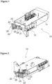
Figure 1 - is the rear perspective view of the board holder related to an embodiment of the present invention. -
Figure 2 - is the perspective view of the board holder shown inFigure 1 from a different angle. -
Figure 3 - is the perspective view of a thermal barrier member suitable to be placed into the board holder of the present invention. -
Figure 4 - is the top view of the thermal barrier member suitable to be placed into the board holder of the present invention. -
Figure 5 - is the front view of the board holder of the present invention. -
Figure 6 - is the perspective view of the board holder of the present invention and the thermal barrier member to be positioned thereon. -
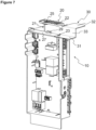
Figure 7 - is the perspective view of the thermal barrier member shown inFigure 6 as positioned in the board holder. -
Figure 8 - is the partial perspective view of the thermal barrier member showing the third wing thereof as placed in the board holder as shown inFigure 7 . -
Figure 9 - is the perspective view of the board holder of the present invention as connected to a panel of the household appliance. -
Figure 10 - is the top view of the connected board holder as shown inFigure 9 . -
Figure 11 - is the partial perspective view of the board holder of the present invention as connected to one of the two adjacent panels. -
Figure 12 - is the rear perspective view of a household appliance which is suitable for using therein the board holder of the present invention. - The elements illustrated in the figures are numbered as follows:
- 10.
- Board holder
11. Inner receptacle - 20.
- Fixing means
21. Housing
22. Support protrusion
23. Coupling protrusion
24. Cable holder
25. Fixing hole
251. Fixing member - 26.
- Mounting base
- 27.
- First connection wall
- 28.
- Second connection wall
- 29.
- Movement limiting member
- 30.
- Thermal barrier member
31. First wing
311. Coupling hole - 32.
- Second wing
- 33.
- Base
- 34.
- Third wing
341. Connection hole - 100.
- Household appliance
101. Body
102. Panel - X.
- Longitudinal axis of the household appliance
- The household appliance (100) of the present invention comprises a body (101); a panel (102) which is disposed on an accessible exterior surface of the body (101); and a board holder (10) which is suitable for being disposed on the surface of the panel (102) facing the inside of the body (101) and which is suitable for enclosing electronic components and sockets therein. The board holder (10) comprises important electronic components for the operation of the household appliance (100) and enables the same to be connected to the body (101) in a fixed manner.
- The household appliance (100) of the present invention further comprises a fixing means (20) which is suitable for connecting the board holder (10) to the panel (102); and at least one thermal barrier member (30) which is at least partially disposed in said fixing means (20). The board holder (10) has an inner receptacle (11), and the thermal barrier member (30) is used in said inner receptacle (11) to prevent side effects caused by the heat generated around the electronic components and the existing sockets. Since the thermal barrier member (30) is positioned directly on the board holder (10), there is no need to mount the thermal barrier member (30) in the body (101). Since said thermal barrier member (30) does not require mounting to the body (101), the need for one or more possible mounting openings is eliminated. Moreover, the need for adding fixing members is eliminated, thus preventing a possible loss of strength. Since said thermal barrier member (30) can be disposed in the fixing means (20), the need for performing additional operations on the assembly line is eliminated. Both the board holder (10) and the thermal barrier member (30) are enabled to be mounted at the same time, thus reducing the number of assembly operations.
- In an embodiment of the present invention, the fixing means (20) comprises a housing (21) having a mounting base (26) whereon the thermal barrier member (30) is positioned. As shown in
Figure 7 , by means of said housing (21), the thermal barrier member (30) is kept in the fixing means (20) without the need to connect the same to the body (101) of the household appliance (100). - In an embodiment of the present invention, as shown in
Figure 1 , the housing (21) comprises a coupling protrusion (23) shaped and formed according to at least one coupling hole (311) on the thermal barrier member (30). While the number of said coupling holes (311) and the opposing coupling protrusions (23) can be increased, the form of the preferably inclined surface of the coupling protrusion (23) can be also changed. By means of said inclined surface, the coupling hole (311) of the thermal barrier member (30), which is slid on the mounting base (26), can be easily engaged with the appropriate coupling protrusion (23). Accordingly,Figure 6 shows the thermal barrier member (30) which is not mounted to the board holder (10), andFigure 7 shows the position of the thermal barrier member (30) in the housing (21) when mounted. - In an embodiment of the present invention, the fixing means (20) comprises a first connection wall (27) and a second connection wall (28) which contact the mounting base (26) therein and which are positioned opposite to each other. As shown in
Figures 1 and 2 , the fixing means (20) is configured to have a U-section by means of the first connection wall (27) and the second connection wall (28), and the second connection wall (28) also enables the board holder (10) to be fixed to the panel (102). The first connection wall (27) is one of the lateral edges of the board holder (10) forming the inner receptacle (11), and is positioned opposite to the second connection wall (28). - In an embodiment of the present invention, a plurality of support protrusions (22) may be provided on the second connection wall (28). Thus, the strength of said second connection wall (28) configured to engage with the panel (102), is increased. As shown in
Figure 9 , on the second connection wall (28), a fixing hole (25) is provided, which is suitable for passing at least one fixing member (251) therethrough to be attached to the panel (102) on the household appliance (100). The number of said fixing hole (25) may be more than one, and is configured and sized to allow a screw or bolt to pass through as the fixing member (251). - In an embodiment of the present invention, the fixing means (20) comprises a movement limiting member (29) which is provided on the first connection wall (27) with a flat surface and which limits the movement of the thermal barrier member (30). The movement limiting member (29) is preferably in the form of a protrusion and is manufactured as integrated with the first connection wall (27). The movement limiting member (29) is formed in a position close to the mounting base (26) and a gap is left therebetween to enable the thermal barrier member (30) to pass.
- In an embodiment of the present invention, the thermal barrier member (3) comprises a base (33), and a first wing (31) and a second wing (32) which extend in opposite directions from said base (33). As shown in
Figure 2 , the first wing (31) and the second wing (32), which extend opposite to each other in a "Z" form, provide better thermal insulation. The metal barrier can be easily shaped by bending and cutting operations without the need for complex production operations such as plastic injection or deep metal drawing. In a preferred embodiment of the present invention, the second wing (32) has a wider cross-section compared to the first wing (31) and provides heat dissipation more effectively. - In an embodiment of the present invention, on the first wing (31), there is a coupling hole (311) which is suitable for engaging with the coupling protrusion (23) provided on the fixing means (20). Said coupling hole (311) provided on the first wing (31) extending parallel to the mounting base (26) prevents the thermal barrier member (30) from moving back in the direction the same is slid for assembly. In another embodiment of the present invention, there may be a plurality of coupling holes (311) which may have different cross-sections and dimensions.
- In an embodiment of the present invention, the thermal barrier member (30) comprises a third wing (34) which is positioned in the same direction as the first wing (31) and which has a connection hole (341) aligning with a fixing hole (25) provided on the fixing means (20). As shown in
Figure 8 , said third wing (34) extends parallel to the first wing (31), and by means of the connection hole (341) of the third wing (34), the thermal barrier member (30) is also connected to the panel (102) by means of a fixing member (251) such as screw or bolt passing therethrough. Said third wing (34) also bears against the inner part of the second connection wall (28). - In an embodiment of the present invention, the fixing means (20) comprises a hook-shaped cable holder (24) which extends from the board holder (10) so as to face the fixing means (20). Referring to
Figure 9 , by means of said cable holder (24), the cable group suitable for passing over the board holder (10) is enabled to be guided in an appropriate direction. Said cable holder (24) is preferably configured in the form of an "L". - In an embodiment of the present invention, the thermal barrier member (30) may have a galvanized coating to provide better thermal insulation and increase durability. The galvanized metal thermal barrier member (30) is coated with zinc so as to make the same more resistant to corrosion/rusting.
- The household appliance (100) of the present invention may be a laundry dryer or a washing machine. By means of the present invention, a household appliance (100) is realized, comprising a board holder (10) wherein cost and labor are reduced and safety features are increased.
Claims (13)
- A household appliance (100) comprising a body (101); a panel (102) which is disposed on an accessible exterior surface of the body (101); and a board holder (10) which is suitable for being disposed on the surface of the panel (102) facing the inside of the body (101) and which is suitable for enclosing a circuit board therein, characterized by a fixing means (20) which is suitable for connecting the board holder (10) to the panel (102); and at least one thermal barrier member (30) which is at least partially disposed in said fixing means (20).
- A household appliance (100) as in Claim 1, characterized by the fixing means (20) comprising a housing (21) having a mounting base (26) whereon the thermal barrier member (30) is positioned.
- A household appliance (100) as in Claim 2, characterized by the housing (21) comprising a coupling protrusion (23) shaped according to at least one coupling hole (311) on the thermal barrier member (30).
- A household appliance (100) as in Claim 2 or 3, characterized by the fixing means (20) having a U-shaped cross-section and comprising a first connection wall (27) and a second connection wall (28) which contact the mounting base (26) and which are positioned opposite to each other.
- A household appliance (100) as in Claim 4, characterized by the fixing means (20) comprising a fixing hole (25) which is provided on the second connection wall (28) and which is suitable for passing at least one fixing member (251) therethrough to be attached to the panel (102).
- A household appliance (100) as in Claim 4 or 5, characterized by a movement limiting member (29) which is provided on the first connection wall (27) and which limits the movement of the thermal barrier member (30).
- A household appliance (100) as in any one of the above claims, characterized by the thermal barrier member (3) comprising a base (33), and a first wing (31) and a second wing (32) which extend in opposite directions from said base (33).
- A household appliance (100) as in Claim 7, characterized by the thermal barrier member (30) comprising the first wing (31) having a coupling hole (311) which is suitable for engaging with the coupling protrusion (23) provided on the fixing means (20).
- A household appliance (100) as in Claim 7 or 8, characterized by a third wing (34) which is positioned in the same direction as the first wing (31) of the thermal barrier member (30) and which has a connection hole (341) aligning with a fixing hole (25) provided on the fixing means (20).
- A household appliance (100) as in any one of the above claims, characterized by a hook-shaped cable holder (24) which extends from the board holder (10) so as to face the fixing means (20).
- A household appliance (100) as in any one of the above claims, characterized by the thermal barrier member (30) having a galvanized coating.
- A household appliance (100) as in any one of the above claims, which is a laundry dryer.
- A household appliance (100) as in any one of Claims 1 to 11, which is a washing machine.
Applications Claiming Priority (1)
| Application Number | Priority Date | Filing Date | Title |
|---|---|---|---|
| TR202221648 | 2022-12-30 |
Publications (2)
| Publication Number | Publication Date |
|---|---|
| EP4393372A1 true EP4393372A1 (en) | 2024-07-03 |
| EP4393372B1 EP4393372B1 (en) | 2025-10-08 |
Family
ID=89378544
Family Applications (1)
| Application Number | Title | Priority Date | Filing Date |
|---|---|---|---|
| EP23220165.7A Active EP4393372B1 (en) | 2022-12-30 | 2023-12-22 | A household appliance comprising a board holder |
Country Status (1)
| Country | Link |
|---|---|
| EP (1) | EP4393372B1 (en) |
Citations (6)
| Publication number | Priority date | Publication date | Assignee | Title |
|---|---|---|---|---|
| KR20000013747A (en) * | 1998-08-12 | 2000-03-06 | 구자홍 | Fixing structure of circuit substrate for washing machine |
| CN101126202A (en) * | 2006-08-15 | 2008-02-20 | 金羚电器有限公司 | Washing machine electronic controller and washing machine using the same |
| US20080196751A1 (en) * | 2007-02-06 | 2008-08-21 | Electrolux Home Products, Inc. | Dishwasher with accessible control unit, and associated method |
| WO2011080146A1 (en) * | 2009-12-30 | 2011-07-07 | Arcelik Anonim Sirketi | A household appliance comprising an electronic component |
| WO2015188973A1 (en) * | 2014-06-12 | 2015-12-17 | Arcelik Anonim Sirketi | A household appliance comprising a printed circuit board |
| WO2019206250A1 (en) * | 2018-04-26 | 2019-10-31 | 青岛海尔滚筒洗衣机有限公司 | Mounting structure for computer board box, and washing machine |
-
2023
- 2023-12-22 EP EP23220165.7A patent/EP4393372B1/en active Active
Patent Citations (6)
| Publication number | Priority date | Publication date | Assignee | Title |
|---|---|---|---|---|
| KR20000013747A (en) * | 1998-08-12 | 2000-03-06 | 구자홍 | Fixing structure of circuit substrate for washing machine |
| CN101126202A (en) * | 2006-08-15 | 2008-02-20 | 金羚电器有限公司 | Washing machine electronic controller and washing machine using the same |
| US20080196751A1 (en) * | 2007-02-06 | 2008-08-21 | Electrolux Home Products, Inc. | Dishwasher with accessible control unit, and associated method |
| WO2011080146A1 (en) * | 2009-12-30 | 2011-07-07 | Arcelik Anonim Sirketi | A household appliance comprising an electronic component |
| WO2015188973A1 (en) * | 2014-06-12 | 2015-12-17 | Arcelik Anonim Sirketi | A household appliance comprising a printed circuit board |
| WO2019206250A1 (en) * | 2018-04-26 | 2019-10-31 | 青岛海尔滚筒洗衣机有限公司 | Mounting structure for computer board box, and washing machine |
Also Published As
| Publication number | Publication date |
|---|---|
| EP4393372B1 (en) | 2025-10-08 |
Similar Documents
| Publication | Publication Date | Title |
|---|---|---|
| US20090179116A1 (en) | Cable management side bracket | |
| JP4304111B2 (en) | Electrical junction box | |
| JP4445819B2 (en) | Electrical junction box | |
| US20090090534A1 (en) | Cable management patch panel system with vertical ducting | |
| EP4393372B1 (en) | A household appliance comprising a board holder | |
| CN104160715B (en) | System for forming a modular switchboard and method for assembling the same | |
| KR100375062B1 (en) | Wall-mounted Installation Housing | |
| JP7599783B2 (en) | Cabinets for electrical and electronic equipment | |
| EP3155160B1 (en) | A household appliance comprising a printed circuit board | |
| TR2022021648A2 (en) | A HOME DEVICE WITH A CARD HOLDER | |
| US6826058B1 (en) | Telecommunications panel flame shield and wire trough | |
| JP4411458B2 (en) | Electronic device housing structure | |
| JP3821007B2 (en) | Distribution board | |
| EP4394105A1 (en) | A household appliance comprising a board holder and a board holder group | |
| JP5456603B2 (en) | Stove | |
| CN211985058U (en) | Electric control device assembly and cooking utensil with same | |
| EP3804037B1 (en) | Conductor connection device as well as printed circuit board and utility meter comprising same | |
| JP7301461B2 (en) | Electrical and electronic equipment storage cabinet | |
| KR20100119277A (en) | Connector mounting on pcb | |
| KR200146312Y1 (en) | Monitor's printed circuit board fixing device | |
| KR960009896Y1 (en) | Door for microwave oven | |
| JP3041628U (en) | Firewall equipment | |
| JP4640202B2 (en) | Harness protector | |
| JP2017224453A (en) | Circuit breaker | |
| KR20250120621A (en) | Distribution board capable of preventing safety accidents |
Legal Events
| Date | Code | Title | Description |
|---|---|---|---|
| PUAI | Public reference made under article 153(3) epc to a published international application that has entered the european phase |
Free format text: ORIGINAL CODE: 0009012 |
|
| STAA | Information on the status of an ep patent application or granted ep patent |
Free format text: STATUS: REQUEST FOR EXAMINATION WAS MADE |
|
| 17P | Request for examination filed |
Effective date: 20231222 |
|
| AK | Designated contracting states |
Kind code of ref document: A1 Designated state(s): AL AT BE BG CH CY CZ DE DK EE ES FI FR GB GR HR HU IE IS IT LI LT LU LV MC ME MK MT NL NO PL PT RO RS SE SI SK SM TR |
|
| GRAP | Despatch of communication of intention to grant a patent |
Free format text: ORIGINAL CODE: EPIDOSNIGR1 |
|
| STAA | Information on the status of an ep patent application or granted ep patent |
Free format text: STATUS: GRANT OF PATENT IS INTENDED |
|
| RIC1 | Information provided on ipc code assigned before grant |
Ipc: A47L 15/46 20060101ALN20250430BHEP Ipc: D06F 39/12 20060101ALI20250430BHEP Ipc: D06F 34/00 20200101ALI20250430BHEP Ipc: A47L 15/42 20060101AFI20250430BHEP |
|
| INTG | Intention to grant announced |
Effective date: 20250526 |
|
| GRAS | Grant fee paid |
Free format text: ORIGINAL CODE: EPIDOSNIGR3 |
|
| GRAA | (expected) grant |
Free format text: ORIGINAL CODE: 0009210 |
|
| STAA | Information on the status of an ep patent application or granted ep patent |
Free format text: STATUS: THE PATENT HAS BEEN GRANTED |
|
| AK | Designated contracting states |
Kind code of ref document: B1 Designated state(s): AL AT BE BG CH CY CZ DE DK EE ES FI FR GB GR HR HU IE IS IT LI LT LU LV MC ME MK MT NL NO PL PT RO RS SE SI SK SM TR |
|
| REG | Reference to a national code |
Ref country code: GB Ref legal event code: FG4D Ref country code: CH Ref legal event code: F10 Free format text: ST27 STATUS EVENT CODE: U-0-0-F10-F00 (AS PROVIDED BY THE NATIONAL OFFICE) Effective date: 20251008 |
|
| REG | Reference to a national code |
Ref country code: DE Ref legal event code: R096 Ref document number: 602023007324 Country of ref document: DE |
|
| REG | Reference to a national code |
Ref country code: IE Ref legal event code: FG4D |
|
| PGFP | Annual fee paid to national office [announced via postgrant information from national office to epo] |
Ref country code: DE Payment date: 20251211 Year of fee payment: 3 |
|
| PGFP | Annual fee paid to national office [announced via postgrant information from national office to epo] |
Ref country code: AT Payment date: 20260113 Year of fee payment: 3 |
|
| PGFP | Annual fee paid to national office [announced via postgrant information from national office to epo] |
Ref country code: TR Payment date: 20251105 Year of fee payment: 3 |
|
| REG | Reference to a national code |
Ref country code: NL Ref legal event code: MP Effective date: 20251008 |
|
| REG | Reference to a national code |
Ref country code: AT Ref legal event code: MK05 Ref document number: 1844157 Country of ref document: AT Kind code of ref document: T Effective date: 20251008 |
|
| PG25 | Lapsed in a contracting state [announced via postgrant information from national office to epo] |
Ref country code: NL Free format text: LAPSE BECAUSE OF FAILURE TO SUBMIT A TRANSLATION OF THE DESCRIPTION OR TO PAY THE FEE WITHIN THE PRESCRIBED TIME-LIMIT Effective date: 20251008 |
|
| PG25 | Lapsed in a contracting state [announced via postgrant information from national office to epo] |
Ref country code: ES Free format text: LAPSE BECAUSE OF FAILURE TO SUBMIT A TRANSLATION OF THE DESCRIPTION OR TO PAY THE FEE WITHIN THE PRESCRIBED TIME-LIMIT Effective date: 20251008 |
|
| REG | Reference to a national code |
Ref country code: LT Ref legal event code: MG9D |
|
| PG25 | Lapsed in a contracting state [announced via postgrant information from national office to epo] |
Ref country code: NO Free format text: LAPSE BECAUSE OF FAILURE TO SUBMIT A TRANSLATION OF THE DESCRIPTION OR TO PAY THE FEE WITHIN THE PRESCRIBED TIME-LIMIT Effective date: 20260108 |
|
| PG25 | Lapsed in a contracting state [announced via postgrant information from national office to epo] |
Ref country code: HR Free format text: LAPSE BECAUSE OF FAILURE TO SUBMIT A TRANSLATION OF THE DESCRIPTION OR TO PAY THE FEE WITHIN THE PRESCRIBED TIME-LIMIT Effective date: 20251008 Ref country code: FI Free format text: LAPSE BECAUSE OF FAILURE TO SUBMIT A TRANSLATION OF THE DESCRIPTION OR TO PAY THE FEE WITHIN THE PRESCRIBED TIME-LIMIT Effective date: 20251008 Ref country code: AT Free format text: LAPSE BECAUSE OF FAILURE TO SUBMIT A TRANSLATION OF THE DESCRIPTION OR TO PAY THE FEE WITHIN THE PRESCRIBED TIME-LIMIT Effective date: 20251008 |
|
| PG25 | Lapsed in a contracting state [announced via postgrant information from national office to epo] |
Ref country code: RS Free format text: LAPSE BECAUSE OF FAILURE TO SUBMIT A TRANSLATION OF THE DESCRIPTION OR TO PAY THE FEE WITHIN THE PRESCRIBED TIME-LIMIT Effective date: 20260108 |
|
| PG25 | Lapsed in a contracting state [announced via postgrant information from national office to epo] |
Ref country code: IS Free format text: LAPSE BECAUSE OF FAILURE TO SUBMIT A TRANSLATION OF THE DESCRIPTION OR TO PAY THE FEE WITHIN THE PRESCRIBED TIME-LIMIT Effective date: 20260208 |
|
| PG25 | Lapsed in a contracting state [announced via postgrant information from national office to epo] |
Ref country code: PT Free format text: LAPSE BECAUSE OF FAILURE TO SUBMIT A TRANSLATION OF THE DESCRIPTION OR TO PAY THE FEE WITHIN THE PRESCRIBED TIME-LIMIT Effective date: 20260209 |
|
| PG25 | Lapsed in a contracting state [announced via postgrant information from national office to epo] |
Ref country code: PL Free format text: LAPSE BECAUSE OF FAILURE TO SUBMIT A TRANSLATION OF THE DESCRIPTION OR TO PAY THE FEE WITHIN THE PRESCRIBED TIME-LIMIT Effective date: 20251008 |
|
| PG25 | Lapsed in a contracting state [announced via postgrant information from national office to epo] |
Ref country code: LV Free format text: LAPSE BECAUSE OF FAILURE TO SUBMIT A TRANSLATION OF THE DESCRIPTION OR TO PAY THE FEE WITHIN THE PRESCRIBED TIME-LIMIT Effective date: 20251008 |
|
| PG25 | Lapsed in a contracting state [announced via postgrant information from national office to epo] |
Ref country code: BG Free format text: LAPSE BECAUSE OF FAILURE TO SUBMIT A TRANSLATION OF THE DESCRIPTION OR TO PAY THE FEE WITHIN THE PRESCRIBED TIME-LIMIT Effective date: 20251008 |
|
| PG25 | Lapsed in a contracting state [announced via postgrant information from national office to epo] |
Ref country code: RO Free format text: LAPSE BECAUSE OF FAILURE TO SUBMIT A TRANSLATION OF THE DESCRIPTION OR TO PAY THE FEE WITHIN THE PRESCRIBED TIME-LIMIT Effective date: 20251008 |
|
| PG25 | Lapsed in a contracting state [announced via postgrant information from national office to epo] |
Ref country code: LT Free format text: LAPSE BECAUSE OF FAILURE TO SUBMIT A TRANSLATION OF THE DESCRIPTION OR TO PAY THE FEE WITHIN THE PRESCRIBED TIME-LIMIT Effective date: 20251008 |
|
| PG25 | Lapsed in a contracting state [announced via postgrant information from national office to epo] |
Ref country code: SM Free format text: LAPSE BECAUSE OF FAILURE TO SUBMIT A TRANSLATION OF THE DESCRIPTION OR TO PAY THE FEE WITHIN THE PRESCRIBED TIME-LIMIT Effective date: 20251008 |
|
| PG25 | Lapsed in a contracting state [announced via postgrant information from national office to epo] |
Ref country code: MC Free format text: LAPSE BECAUSE OF FAILURE TO SUBMIT A TRANSLATION OF THE DESCRIPTION OR TO PAY THE FEE WITHIN THE PRESCRIBED TIME-LIMIT Effective date: 20251008 |
|
| PG25 | Lapsed in a contracting state [announced via postgrant information from national office to epo] |
Ref country code: DK Free format text: LAPSE BECAUSE OF FAILURE TO SUBMIT A TRANSLATION OF THE DESCRIPTION OR TO PAY THE FEE WITHIN THE PRESCRIBED TIME-LIMIT Effective date: 20251008 |
|
| PG25 | Lapsed in a contracting state [announced via postgrant information from national office to epo] |
Ref country code: IT Free format text: LAPSE BECAUSE OF FAILURE TO SUBMIT A TRANSLATION OF THE DESCRIPTION OR TO PAY THE FEE WITHIN THE PRESCRIBED TIME-LIMIT Effective date: 20251008 |
|
| PG25 | Lapsed in a contracting state [announced via postgrant information from national office to epo] |
Ref country code: EE Free format text: LAPSE BECAUSE OF FAILURE TO SUBMIT A TRANSLATION OF THE DESCRIPTION OR TO PAY THE FEE WITHIN THE PRESCRIBED TIME-LIMIT Effective date: 20251008 |
|
| PG25 | Lapsed in a contracting state [announced via postgrant information from national office to epo] |
Ref country code: CZ Free format text: LAPSE BECAUSE OF FAILURE TO SUBMIT A TRANSLATION OF THE DESCRIPTION OR TO PAY THE FEE WITHIN THE PRESCRIBED TIME-LIMIT Effective date: 20251008 |
|
| PG25 | Lapsed in a contracting state [announced via postgrant information from national office to epo] |
Ref country code: SK Free format text: LAPSE BECAUSE OF FAILURE TO SUBMIT A TRANSLATION OF THE DESCRIPTION OR TO PAY THE FEE WITHIN THE PRESCRIBED TIME-LIMIT Effective date: 20251008 |
|
| PG25 | Lapsed in a contracting state [announced via postgrant information from national office to epo] |
Ref country code: SE Free format text: LAPSE BECAUSE OF FAILURE TO SUBMIT A TRANSLATION OF THE DESCRIPTION OR TO PAY THE FEE WITHIN THE PRESCRIBED TIME-LIMIT Effective date: 20251008 |
|
| PLBE | No opposition filed within time limit |
Free format text: ORIGINAL CODE: 0009261 |
|
| STAA | Information on the status of an ep patent application or granted ep patent |
Free format text: STATUS: NO OPPOSITION FILED WITHIN TIME LIMIT |