EP4393351A1 - Removable cooking vessel heater safety lock system with status indicator - Google Patents
Removable cooking vessel heater safety lock system with status indicator Download PDFInfo
- Publication number
- EP4393351A1 EP4393351A1 EP23220463.6A EP23220463A EP4393351A1 EP 4393351 A1 EP4393351 A1 EP 4393351A1 EP 23220463 A EP23220463 A EP 23220463A EP 4393351 A1 EP4393351 A1 EP 4393351A1
- Authority
- EP
- European Patent Office
- Prior art keywords
- latch
- food processing
- processing appliance
- carrier
- heating component
- Prior art date
- Legal status (The legal status is an assumption and is not a legal conclusion. Google has not performed a legal analysis and makes no representation as to the accuracy of the status listed.)
- Granted
Links
Images



Classifications
-
- A—HUMAN NECESSITIES
- A47—FURNITURE; DOMESTIC ARTICLES OR APPLIANCES; COFFEE MILLS; SPICE MILLS; SUCTION CLEANERS IN GENERAL
- A47J—KITCHEN EQUIPMENT; COFFEE MILLS; SPICE MILLS; APPARATUS FOR MAKING BEVERAGES
- A47J43/00—Implements for preparing or holding food, not provided for in other groups of this subclass
- A47J43/04—Machines for domestic use not covered elsewhere, e.g. for grinding, mixing, stirring, kneading, emulsifying, whipping or beating foodstuffs, e.g. power-driven
- A47J43/07—Parts or details, e.g. mixing tools, whipping tools
- A47J43/075—Safety devices
- A47J43/0761—Safety devices for machines with tools driven from the lower side
-
- A—HUMAN NECESSITIES
- A47—FURNITURE; DOMESTIC ARTICLES OR APPLIANCES; COFFEE MILLS; SPICE MILLS; SUCTION CLEANERS IN GENERAL
- A47J—KITCHEN EQUIPMENT; COFFEE MILLS; SPICE MILLS; APPARATUS FOR MAKING BEVERAGES
- A47J27/00—Cooking-vessels
- A47J27/004—Cooking-vessels with integral electrical heating means
-
- A—HUMAN NECESSITIES
- A47—FURNITURE; DOMESTIC ARTICLES OR APPLIANCES; COFFEE MILLS; SPICE MILLS; SUCTION CLEANERS IN GENERAL
- A47J—KITCHEN EQUIPMENT; COFFEE MILLS; SPICE MILLS; APPARATUS FOR MAKING BEVERAGES
- A47J43/00—Implements for preparing or holding food, not provided for in other groups of this subclass
- A47J43/04—Machines for domestic use not covered elsewhere, e.g. for grinding, mixing, stirring, kneading, emulsifying, whipping or beating foodstuffs, e.g. power-driven
- A47J43/046—Machines for domestic use not covered elsewhere, e.g. for grinding, mixing, stirring, kneading, emulsifying, whipping or beating foodstuffs, e.g. power-driven with tools driven from the bottom side
-
- A—HUMAN NECESSITIES
- A47—FURNITURE; DOMESTIC ARTICLES OR APPLIANCES; COFFEE MILLS; SPICE MILLS; SUCTION CLEANERS IN GENERAL
- A47J—KITCHEN EQUIPMENT; COFFEE MILLS; SPICE MILLS; APPARATUS FOR MAKING BEVERAGES
- A47J43/00—Implements for preparing or holding food, not provided for in other groups of this subclass
- A47J43/04—Machines for domestic use not covered elsewhere, e.g. for grinding, mixing, stirring, kneading, emulsifying, whipping or beating foodstuffs, e.g. power-driven
- A47J43/07—Parts or details, e.g. mixing tools, whipping tools
- A47J43/0716—Parts or details, e.g. mixing tools, whipping tools for machines with tools driven from the lower side
-
- A—HUMAN NECESSITIES
- A47—FURNITURE; DOMESTIC ARTICLES OR APPLIANCES; COFFEE MILLS; SPICE MILLS; SUCTION CLEANERS IN GENERAL
- A47J—KITCHEN EQUIPMENT; COFFEE MILLS; SPICE MILLS; APPARATUS FOR MAKING BEVERAGES
- A47J43/00—Implements for preparing or holding food, not provided for in other groups of this subclass
- A47J43/04—Machines for domestic use not covered elsewhere, e.g. for grinding, mixing, stirring, kneading, emulsifying, whipping or beating foodstuffs, e.g. power-driven
- A47J43/07—Parts or details, e.g. mixing tools, whipping tools
- A47J43/0727—Mixing bowls
-
- A—HUMAN NECESSITIES
- A47—FURNITURE; DOMESTIC ARTICLES OR APPLIANCES; COFFEE MILLS; SPICE MILLS; SUCTION CLEANERS IN GENERAL
- A47J—KITCHEN EQUIPMENT; COFFEE MILLS; SPICE MILLS; APPARATUS FOR MAKING BEVERAGES
- A47J2202/00—Devices having temperature indicating means
Definitions
- a food processing appliance includes a base.
- a heating component operably connects to the base and is configured to selectively receive a vessel and generate heat above a temperature threshold.
- At least one latch includes a locked position that secures the heating component to the vessel and an unlocked position that permits removal of the heating component from the vessel.
- a temperature dependent catch assembly is configured to retain the at least one latch in the locked position above the temperature threshold and release the at least one latch below the temperature threshold.
- the heating component 14 is removably connected to the base 12 and the vessel 16 ( FIG. 3 ).
- the at least one latch 18 may, therefore, selectively connect the heating component 14 to the base 12 and/or the vessel 16, and the catch assembly 20 prevents movement of the at least one latch 18 above the temperature threshold. Therefore, it should be appreciated that the principle operation of the at least one latch 18 and catch assembly 20 may be applied to various coupling configurations of the base 12, the vessel 16, and the heating component 14. More particularly, the latch 18 and catch assembly 20 may prevent movement of the vessel 16 relative to the heating component 14 or the base 12 relative to the heating component 14.
- the vessel 16 may include a variety of tools 22 ( FIG. 2 ) that process the food contents in the vessel 16.
- the vessel 16 may be configured as a blender and the tool 22 may include blending blades rotatable within the vessel 16.
- the vessel 16 may include a vessel body 32 extending between a bottom surface 34 and a top opening 36 to define a cavity 38 ( FIG. 2 ).
- a handle 39 may be connected to the vessel body 32 to facilitate moving the vessel 16 on and off the base 12, the heating component 14, and/or around a kitchen environment.
- the bottom surface 34 defines an annular sidewall 40 including an interior surface 41 defining at least one ridge 42 for connecting to the at least one latch 18 ( FIG. 2 ).
- Each latch 18 may be slidable within the housing 43 between the unlocked position and the locked position as indicated by the arrows in FIG. 4 . More particularly, the latch 18 may slide outwardly (e.g., in a direction towards on outer perimeter of the housing 43) to enter the locked position.
- the latch interface head 48 includes an angled top surface 52 to facilitate inward movement as a result of downward pressure from the annular sidewall 40 of the vessel 16. Likewise, the latch interface head 48 may include an angled bottom surface 53 to facilitate connection to the at least one ridge 42.
- the temperature dependent catch assembly 20 may be at least partially formed of a shape-memory alloy. More particularly, the temperature dependent catch assembly 20 includes a wire 54 formed of a shape-memory alloy that compresses above the temperature threshold and decompresses below the temperature threshold.
- the wire 54 wraps at least partially around at least one carrier 56 that moves in response to the compression and decompression of the wire 54.
- the at least one carrier 56 may include a pair of diametrically opposed carriers including a first and second carrier 56.
- the number of carriers 56 may be equal to or less than the number of latches 18 as, during operation, the carrier 56 facilitates movement of the latches 18. Stated another way, each one of the latches 18 may be operably connected to one of the carriers 56.
- the latch 18 includes a pair of posts 86
- the retainer plate 72 includes a pair of post receiving chambers 88 that slideably receive the posts 86 and guide relative movement between the latch 18 and the retainer plate 72. More particularly, the retainer plate 72 may be statically coupled to the housing 43 and the latch associated with the retainer plate 72 may travel relative thereto. In some embodiments, the second pivot joint 62 pivotally connected to the retainer plate 72.
- a first color indicia on the viewable component may be visible when the latch 18 is in the unlocked position and a second color indicia on the viewable component may be visible when the latch 18 is in the locked position.
- a light such as a light-emitting diode (LED) may be located on the viewable component and only visible in one of the locked and unlocked positions.
- the indicator component may be a physical structure, such as an indicator member 92 that is connected to the heating component 14 and moves into user visibility during the compression and decompression of the wire 54 to notify a user if the latch 18 is retained or released by the catch assembly 20 (i.e., if the latch is in the locked or unlocked position).
- the indicator member 92 may extend out of a through hole in the housing 43 in one of the locked or the unlocked positions and retract back into the through hole in the other of the locked or unlocked positions.
- the indicator member 92 may include a color indicia or a light that becomes visible during movement of the latch 18 between positions.
- the indicator member 92 may be physically connected to the previously described viewable component and is visible through the window 90.
- the indicator component may of the aforedescribed examples may be configured to notify a user of the latch 18 (i.e., locked and unlocked position) or the position of other components such as the pivot member 58 or the carrier 56 that move as a result of compression and decompression of the wire 54.
- a food processing appliance includes a base.
- a heating component operably connects to the base and is configured to selectively receive a vessel and generate heat above a temperature threshold.
- At least one latch includes a locked position that secures the heating component to the vessel and an unlocked position that permits removal of the heating component from the vessel.
- a temperature dependent catch assembly is configured to retain the at least one latch in the locked position above the temperature threshold and releases the at least one latch below the temperature threshold.
- a temperature dependent catch assembly is at least partially formed of a shape-memory alloy.
- a temperature dependent catch assembly includes a wire configured to compress above a temperature threshold and decompress below the temperature threshold.
- a wire wraps at least partially around at least one carrier that moves in response to the compression and decompression of the wire and an at least one latch is operably connected to the at least one carrier.
- a carrier defines a track and a wire is located in the track.
- an indicator member is connected to a heating component and is configured to move during the compression and decompression of a wire to notify a user if a latch is retained or released by a temperature dependent catch assembly.
- a retainer plate is statically coupled to a housing.
- a wire is operably connected to a carrier that includes an outer surface that is rounded defining a track and a wire is located in the track.
- an inner surface of a carrier defines a first pivot connection and a pivot member includes a first pivot joint pivotally connected to the first pivot connection.
- a pivot member further includes a second pivot joint pivotally connected to a housing.
- a pivot member includes a boot extending towards a latch that pushes the latch into a locked position when the pivot member is in an articulate position.
- a housing defines a window to a latch for notifying a user that the latch is in an unlocked position.
Landscapes
- Engineering & Computer Science (AREA)
- Food Science & Technology (AREA)
- Mechanical Engineering (AREA)
- Cookers (AREA)
Abstract
Description
- The present disclosure generally relates to a food processing appliance, and, more specifically, to a food processing appliance with a heating component and a temperature dependent catch assembly.
- Food processing appliances typically include several complementary appliances or accessories for various types of food processing. The accessories are typically releasably connected to the food processing appliance. Many of these appliances heat food as part of the food processing functionality (e.g., for making soups and other heated food). As such, a user may be exposed to heated components of the appliance when it is disconnected from the food processing appliance. This exposure can create discomfort to human touch or potentially harm countertops around a kitchen.
- Accordingly, the present disclosure relates to a food processing appliance with a heating component and a temperature dependent catch assembly that only allows a user to remove the appliance after it has cooled below a temperature threshold.
- According to one aspect of the present disclosure, a food processing appliance includes a base. A heating component operably connects to the base and is configured to selectively receive a vessel and generate heat above a temperature threshold. At least one latch includes a locked position that secures the heating component to the vessel and an unlocked position that permits removal of the heating component from the vessel. A temperature dependent catch assembly is configured to retain the at least one latch in the locked position above the temperature threshold and release the at least one latch below the temperature threshold.
- According to another aspect of the present disclosure, a food processing appliance includes a base. A heating component is located in a housing and operably connects to the base and is configured to selectively receive a vessel and generate heat above a temperature threshold. latch includes a locked position that secures the heating component to the vessel and an unlocked position that permits removal of the heating component from the vessel. A temperature dependent catch assembly includes a wire at least partially formed of a shape-memory alloy and a pivot member. The wire compresses above the temperature threshold moving the pivot member to an articulated position in order to push the latch into the locked position and decompress below the temperature threshold to return the pivot member to a non-articulated position and release the latch below the temperature threshold.
- According to yet another aspect of the present disclosure, a food processing appliance includes a base. A heating component is located in a housing and operably connects to the base and is configured to selectively receive a vessel and generate heat above a temperature threshold. latch includes a locked position that secures the heating component to the vessel and an unlocked position that permits removal of the heating component from the vessel. A temperature dependent catch assembly includes a wire formed as a closed loop that is at least partially formed of a shape-memory alloy that compresses above the temperature threshold and decompresses below the temperature threshold. A carrier includes an outer surface that is rounded and defines a track with the wire located in the track. A pivot member includes a boot, the pivot member is pivotally coupled to the carrier with a first pivot joint and the housing with a second pivot joint. The pivot member includes an articulated position when the wire is compressed where the boot pushes the latch in the locked position and an unarticulated position when the wire is decompressed and the latch is released from the locked position.
- These and other features, advantages, and objects of the present disclosure will be further understood and appreciated by those skilled in the art by reference to the following specification, claims, and appended drawings.
- In the drawings:
-
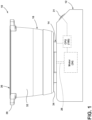
FIG. 1 is a side elevational view of a food processing appliance according to an aspect of the present disclosure; -
FIG. 2 is a side cross-sectional view of a food processing appliance according to an aspect of the present disclosure; -
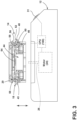
FIG. 3 is a side cross-sectional view of a heating component and a base of a food processing appliance in a disassembled condition according to an aspect of the present disclosure; -
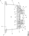
FIG. 4 is a side cross-sectional view of a food processing appliance with a heating component and a vessel according to an aspect of the present disclosure; -
FIG. 5 is an enlarged side cross-sectional view of a food processing appliance with a heating component and a vessel in an unlocked position according to an aspect of the present disclosure; -
FIG. 6 is an enlarged side cross-sectional view of a food processing appliance with a heating component and a vessel in a locked position according to an aspect of the present disclosure; -
FIG. 7 is a top perspective view of a partially disassembled heating component according to an aspect of the present disclosure; -
FIG. 8 is a top perspective view of a partially disassembled latch and housing of a heating component according to an aspect of the present disclosure; and -
FIG. 9 is a side cross-sectional view of a food processing appliance with an indicator component according to an aspect of the present disclosure. - The components in the figures are not necessarily to scale, emphasis instead being placed upon illustrating the principles described herein.
- The present illustrated embodiments reside primarily in combinations of method steps and apparatus components related to a food processing appliance with a heating component and a temperature dependent catch assembly. Accordingly, the apparatus components and method steps have been represented, where appropriate, by conventional symbols in the drawings, showing only those specific details that are pertinent to understanding the embodiments of the present disclosure so as not to obscure the disclosure with details that will be readily apparent to those of ordinary skill in the art having the benefit of the description herein. Further, like numerals in the description and drawings represent like elements.
- For purposes of description herein, the terms "upper," "lower," "right," "left," "rear," "front," "vertical," "horizontal," and derivatives thereof shall relate to the disclosure as oriented in
FIG. 1 . Unless stated otherwise, the term "front" shall refertothe surface of the element closer to an intended viewer, and the term "rear" shall refer to the surface of the element further from the intended viewer. However, it is to be understood that the disclosure may assume various alternative orientations, except where expressly specified to the contrary. It is also to be understood that the specific devices and processes illustrated in the attached drawings, and described in the following specification are simply exemplary embodiments of the inventive concepts defined in the appended claims. Hence, specific dimensions and other physical characteristics relating to the embodiments disclosed herein are not to be considered as limiting, unless the claims expressly state otherwise. - The terms "including," "comprises," "comprising," or any other variation thereof, are intended to cover a non-exclusive inclusion, such that a process, method, article, or apparatus that comprises a list of elements does not include only those elements but may include other elements not expressly listed or inherent to such process, method, article, or apparatus. An element preceded by "comprises a ... " does not, without more constraints, preclude the existence of additional identical elements in the process, method, article, or apparatus that comprises the element.
- Referring to
FIGS. 1-8 ,reference numeral 10 generally designates a food processing appliance. Thefood processing appliance 10 includes abase 12 and aheating component 14 operably connected to thebase 12 and configured to selectively receive avessel 16 and generate heat above a temperature threshold. At least onelatch 18 includes a locked position (FIG. 6 ) that secures theheating component 14 to the vessel and an unlocked position (FIG. 5 ) that permits removal of theheating component 14 from thevessel 16. A temperaturedependent catch assembly 20 is configured to retain the at least onelatch 18 in the locked position above the temperature threshold and release the at least onelatch 18 below the temperature threshold. - With reference now to
FIGS. 1-3 , the temperature threshold may correspond to a temperature that can create discomfort to human skin. For example, the temperature threshold may be about 100° Fahrenheit or more, for example, about 105° Fahrenheit or more, or between about 100° Fahrenheit and about 110° Fahrenheit. In this manner, thecatch assembly 20 is configured to prevent discomfort to a user and/or prevent burning of a kitchen countertop when thevessel 16 and/orheating component 14 is removed and placed thereon. Theheating component 14 may be integral (e.g., permanently connected) to thebase 12, removably connected to the base 12 (FIGS. 3 and4 ), integral with the vessel 16 (FIG. 4 ), or removably connected to the vessel 16 (FIG. 2 ). In some embodiments, theheating component 14 is removably connected to thebase 12 and the vessel 16 (FIG. 3 ). The at least onelatch 18 may, therefore, selectively connect theheating component 14 to thebase 12 and/or thevessel 16, and thecatch assembly 20 prevents movement of the at least onelatch 18 above the temperature threshold. Therefore, it should be appreciated that the principle operation of the at least onelatch 18 andcatch assembly 20 may be applied to various coupling configurations of thebase 12, thevessel 16, and theheating component 14. More particularly, thelatch 18 andcatch assembly 20 may prevent movement of thevessel 16 relative to theheating component 14 or thebase 12 relative to theheating component 14. In addition to heating food within thevessel 16, thevessel 16 may include a variety of tools 22 (FIG. 2 ) that process the food contents in thevessel 16. For example, thevessel 16 may be configured as a blender and thetool 22 may include blending blades rotatable within thevessel 16. - With continued reference to
FIGS. 1-3 , in some embodiments, theheating component 14 is selectively connected to thevessel 16 with the at least onelatch 18. The base 12 may include amotor 24, and acontrol system 100 is operably connected to themotor 24. Themotor 24 is configured to rotatably power a drive mechanism oroutput drive hub 26, which, in turn, rotatably drives thetool 22. Thetool 22 may connect to theoutput drive hub 26 via an input drive hub 28 (FIG. 2 ). An electrical connection 30 (FIGS. 7 and8 ) may connect the base 12 to theheating component 14. Auser interface 31 may be operably connected to thecontrol system 100 for selecting user options relating to the processing functionality (e.g., warming theheating component 14 and functionalities associated with the tool 22). Thevessel 16 may include avessel body 32 extending between abottom surface 34 and atop opening 36 to define a cavity 38 (FIG. 2 ). Ahandle 39 may be connected to thevessel body 32 to facilitate moving thevessel 16 on and off thebase 12, theheating component 14, and/or around a kitchen environment. Thebottom surface 34 defines anannular sidewall 40 including aninterior surface 41 defining at least oneridge 42 for connecting to the at least one latch 18 (FIG. 2 ). - With reference now to
FIGS. 2-6 , theheating component 14 includes ahousing 43 defining acentral aperture 44 for permitting theoutput drive hub 26 and/or theinput drive hub 28 to extend at least partially therethrough and operably connect. The at least onelatch 18 may include, one, two, i.e., a first and asecond latch 18, or more latches 18. Thelatches 18 may be diametrically opposed. More particularly, thehousing 43 may be generally cylindrically shaped and thefirst latch 18 may be located on an opposite side than thesecond latch 18. As best illustrated inFIGS. 5 and6 , eachlatch 18 includes alatch body 46, alatch interface head 48, and alatch neck 50 extending between thelatch body 46 and thelatch interface head 48. Eachlatch 18 may be slidable within thehousing 43 between the unlocked position and the locked position as indicated by the arrows inFIG. 4 . More particularly, thelatch 18 may slide outwardly (e.g., in a direction towards on outer perimeter of the housing 43) to enter the locked position. Thelatch interface head 48 includes an angledtop surface 52 to facilitate inward movement as a result of downward pressure from theannular sidewall 40 of thevessel 16. Likewise, thelatch interface head 48 may include anangled bottom surface 53 to facilitate connection to the at least oneridge 42. While not explicitly shown, the at least oneridge 42 may be located in discrete locations around theinterior surface 41 and equal in number to thelatches 18 or, alternatively, may be formed as an annular step extending around the entireinterior surface 41 of theannular sidewall 40 on thevessel 16. - With reference now to
FIGS. 4-7 , the temperaturedependent catch assembly 20 may be at least partially formed of a shape-memory alloy. More particularly, the temperaturedependent catch assembly 20 includes awire 54 formed of a shape-memory alloy that compresses above the temperature threshold and decompresses below the temperature threshold. Thewire 54 wraps at least partially around at least onecarrier 56 that moves in response to the compression and decompression of thewire 54. The at least onecarrier 56 may include a pair of diametrically opposed carriers including a first andsecond carrier 56. Generally, the number ofcarriers 56 may be equal to or less than the number oflatches 18 as, during operation, thecarrier 56 facilitates movement of thelatches 18. Stated another way, each one of thelatches 18 may be operably connected to one of thecarriers 56. - With reference now to
FIGS. 5 and6 , eachlatch 18 may be operably connected to an associatedcarrier 56 with apivot member 58. Thepivot members 58 each include a first pivot joint 60 pivotally connected to thecarrier 56 and a second pivot joint 62 pivotally coupled to thehousing 43. Thepivot members 58 each also include aboot 63 that, when articulated by energy from the compression, pushes an associatedlatch 18 outwardly upon pivotal moment in a first direction until theangled bottom surface 53 of thelatch interface head 48 extends over the at least oneridge 42. More particularly, as theheating component 14 reaches above the temperature threshold, thewire 54 compresses and moves thecarriers 56 towards one another to cause thepivot members 58 to pivotally move (i.e., articulate) in the first direction thereby pushing bothlatches 18 outwardly into engagement with the at least oneridge 42. Thepivot member 58 includes apivot member body 65 that extends from the first pivot joint 60 to theboot 63. In some embodiments, thelatch 18 includes aboot aperture 67 that accommodates theboot 63 in a non-articulated position (FIG. 5 ). Alatch tab 69 may be located over theboot aperture 67. In such embodiments, as thepivot member 58 is moved to an articulated position (FIG. 6 ), thepivot member body 65 initially pushes against thelatch tab 69, moving thelatch 18 until theboot 63 can articulate out of theboot aperture 67 and into pushing engagement against thelatch tab 69 or a proximate surface of thelatch 18. - With reference now to
FIGS. 7 and8 , eachcarrier 56 includes anouter surface 64 defining atrack 66. Thewire 54 may be configured as a ring-shaped band or closed loop that is retained within eachtrack 66. Thewire 54 may be assembled in a closed loop or otherwise include ends that are otherwise fused, tied, and/or the like to form the closed loop. In some embodiments, thecarriers 56 and/or latches 18 may be biased outwardly by a spring member (not shown), such that thelatches 18 are biased into the unlocked position when thewire 54 is below the temperature threshold. The biasing force of the spring member is overcome when thewire 54 is compressed as a result of exposure to the temperature threshold. Eachcarrier 56 may define a bay 68 (FIG. 7 ) with afirst pivot connection 70 engaged with the first pivot joint 60. Thefirst pivot connection 70 may be engaged with the first pivot joint 60 within thebay 68 and substantially aligned with thewire 54, such that the force of thewire 54 is directly imparted on the first pivot joint 60. - With reference now to
FIG. 8 , thehousing 43 includes at least one retainer plate 72 (e.g., an equal number ofretainer plates 72 to latches 18) that includes abridge portion 76 that extends over the latch 18 (e.g., a pair ofretainer plates 72 for each latch 18). Thebridge portion 76 defines a first cam surface 78 (FIG. 5 ) having afirst abutment step 80 and thelatch 18 defines asecond cam surface 82 defining a second abutment step 84 (FIG. 5 ). The first and second cam surfaces 78, 82 are located between the first and second abutment steps 80, 84 and define space for thecarrier 56 to travel between the compressed and decompressed conditions. Thelatch 18 includes a pair ofposts 86, and theretainer plate 72 includes a pair ofpost receiving chambers 88 that slideably receive theposts 86 and guide relative movement between thelatch 18 and theretainer plate 72. More particularly, theretainer plate 72 may be statically coupled to thehousing 43 and the latch associated with theretainer plate 72 may travel relative thereto. In some embodiments, the second pivot joint 62 pivotally connected to theretainer plate 72. - With reference now to
FIG. 9 , thefood processing appliance 10 may include an indicator component that is configured to notify a user when thevessel 16 and/orheating component 14 can be removed (i.e., once theheating component 14 and/orwire 54 is below the temperature threshold). In some embodiments, the indicator component may include awindow 90 that allows a user to view the position of thelatch 18, thepivot member 58, thecarrier 56, or other components of thefood processing appliance 10 that move as a result of compression and decompression of thewire 54. In some embodiments, the viewable component is color coded. For example, a first color indicia on the viewable component may be visible when thelatch 18 is in the unlocked position and a second color indicia on the viewable component may be visible when thelatch 18 is in the locked position. In still further embodiments, a light, such as a light-emitting diode (LED) may be located on the viewable component and only visible in one of the locked and unlocked positions. In some embodiments, the indicator component may be a physical structure, such as anindicator member 92 that is connected to theheating component 14 and moves into user visibility during the compression and decompression of thewire 54 to notify a user if thelatch 18 is retained or released by the catch assembly 20 (i.e., if the latch is in the locked or unlocked position). In some embodiments, theindicator member 92 may extend out of a through hole in thehousing 43 in one of the locked or the unlocked positions and retract back into the through hole in the other of the locked or unlocked positions. In still further embodiments, theindicator member 92 may include a color indicia or a light that becomes visible during movement of thelatch 18 between positions. In still further embodiments yet, theindicator member 92 may be physically connected to the previously described viewable component and is visible through thewindow 90. The indicator component may of the aforedescribed examples may be configured to notify a user of the latch 18 (i.e., locked and unlocked position) or the position of other components such as thepivot member 58 or thecarrier 56 that move as a result of compression and decompression of thewire 54. - The disclosure is further summarized in the following paragraphs and is further characterized by combinations of any and all of the various aspects described therein.
- According to one aspect of the present disclosure, a food processing appliance includes a base. A heating component operably connects to the base and is configured to selectively receive a vessel and generate heat above a temperature threshold. At least one latch includes a locked position that secures the heating component to the vessel and an unlocked position that permits removal of the heating component from the vessel. A temperature dependent catch assembly is configured to retain the at least one latch in the locked position above the temperature threshold and releases the at least one latch below the temperature threshold
According to another aspect, a temperature dependent catch assembly is at least partially formed of a shape-memory alloy. - According to yet another aspect, a temperature dependent catch assembly includes a wire configured to compress above a temperature threshold and decompress below the temperature threshold.
- According to still yet another aspect, a wire wraps at least partially around at least one carrier that moves in response to the compression and decompression of the wire and an at least one latch is operably connected to the at least one carrier.
- According to another aspect of the present disclosure, at least one latch is slidable between a locked position and an unlocked position.
- According to yet another aspect of the present disclosure, a carrier defines a track and a wire is located in the track.
- According to still another aspect, at least one carrier includes a first carrier and a second carrier in an opposing relationship and at least one latch includes a first latch connected to the first carrier and a second latch connected to the second carrier.
- According to another aspect, an indicator member is connected to a heating component and is configured to move during the compression and decompression of a wire to notify a user if a latch is retained or released by a temperature dependent catch assembly.
- According to yet another aspect, a vessel includes a processing tool configured to be driven by a base.
- According to another aspect of the present disclosure, a food processing appliance includes a base. A heating component is located in a housing and operably connects to the base and is configured to selectively receive a vessel and generate heat above a temperature threshold. latch includes a locked position that secures the heating component to the vessel and an unlocked position that permits removal of the heating component from the vessel. A temperature dependent catch assembly includes a wire at least partially formed of a shape-memory alloy and a pivot member. The wire compresses above the temperature threshold moving the pivot member to an articulated position in order to push the latch into the locked position and decompress below the temperature threshold to return the pivot member to a non-articulated position and release the latch below the temperature threshold.
- According to another aspect, a latch is slideably located in a retainer plate, the retainer plate defines one of a post or a post receiving chamber and the latch includes the other of the post or the post receiving chamber.
- According to yet another aspect, a retainer plate is statically coupled to a housing.
- According to still yet another aspect, a wire is operably connected to a carrier that includes an outer surface that is rounded defining a track and a wire is located in the track.
- According to another aspect, an inner surface of a carrier defines a first pivot connection and a pivot member includes a first pivot joint pivotally connected to the first pivot connection.
- According to yet another aspect, a pivot member further includes a second pivot joint pivotally connected to a housing.
- According to still yet another aspect, a pivot member includes a boot extending towards a latch that pushes the latch into a locked position when the pivot member is in an articulate position.
- According to another aspect, a housing defines a window to a latch for notifying a user that the latch is in an unlocked position.
- According to yet another aspect of the present disclosure, a food processing appliance includes a base. A heating component is located in a housing and operably connects to the base and is configured to selectively receive a vessel and generate heat above a temperature threshold. latch includes a locked position that secures the heating component to the vessel and an unlocked position that permits removal of the heating component from the vessel. A temperature dependent catch assembly includes a wire formed as a closed loop that is at least partially formed of a shape-memory alloy that compresses above the temperature threshold and decompresses below the temperature threshold. A carrier includes an outer surface that is rounded and defines a track with the wire located in the track. A pivot member includes a boot, the pivot member is pivotally coupled to the carrier with a first pivot joint and the housing with a second pivot joint. The pivot member includes an articulated position when the wire is compressed where the boot pushes the latch in the locked position and an unarticulated position when the wire is decompressed and the latch is released from the locked position.
- According to another aspect, an indicator member is connected to a heating component and is configured to move during the compression and decompression of a wire to notify a user if a latch is retained or released by a temperature dependent catch assembly.
- According to yet another aspect, a housing defines a window to a latch for notifying a user that the latch is in an unlocked position.
- It will be understood by one having ordinary skill in the art that construction of the described disclosure and other components is not limited to any specific material. Other exemplary embodiments of the disclosure disclosed herein may be formed from a wide variety of materials, unless described otherwise herein.
- For purposes of this disclosure, the term "coupled" (in all of its forms, couple, coupling, coupled, etc.) generally means the joining of two components (electrical or mechanical) directly or indirectly to one another. Such joining may be stationary in nature or movable in nature. Such joining may be achieved with the two components (electrical or mechanical) and any additional intermediate members being integrally formed as a single unitary body with one another or with the two components. Such joining may be permanent in nature or may be removable or releasable in nature unless otherwise stated.
Claims (15)
- A food processing appliance (10) comprising:a base (12);a heating component (14) operably connected to the base (12) and configured to selectively receive a vessel (16) and generate heat above a temperature threshold;at least one latch (18) including a locked position that secures the heating component (14) to the vessel (16) and an unlocked position that permits removal of the heating component (14) from the vessel (16); anda temperature dependent catch assembly (20) configured to retain the at least one latch (18) in the locked position above the temperature threshold and release the at least one latch (18) below the temperature threshold.
- The food processing appliance (10) of claim 1, wherein the temperature dependent catch assembly (20) is at least partially formed of a shape-memory alloy.
- The food processing appliance (10) of claim 2, wherein the temperature dependent catch assembly (20) includes a wire (54) configured to compress above the temperature threshold and decompress below the temperature threshold.
- The food processing appliance (10) of claim 3, wherein the wire (54) wraps at least partially around at least one carrier (56) that moves in response to the compression and decompression of the wire (54) and the at least one latch (18) is operably coupled to the at least one carrier (56).
- The food processing appliance (10) as in one of claims 1-4, wherein the at least one latch (18) is slidable between the locked position and the unlocked position.
- The food processing appliance (10) of claim 4, wherein the at least one carrier (56) defines a track (66) and the wire (54) is located in the track (66).
- The food processing appliance (10) as in claim 4 or claim 6, wherein the at least one carrier (56) includes first carrier (56) and a second carrier (56) in an opposing relationship and the at least one latch (18) includes a first latch (18) operably coupled to the first carrier (56) and a second latch (18) operably coupled to the second carrier (56).
- The food processing appliance (10) as in claim 3 or claim 4, wherein an indicator member (92) is coupled to the heating component (14) and is configured to move during the compression and decompression of the wire (54) to notify a user if the at least one latch (18) is retained or released by the temperature dependent catch assembly (20).
- The food processing appliance (10) as in one of claims 1-4, wherein the vessel (16) includes a food processing tool (22) configured to be driven by the base (12).
- The food processing appliance (10) as in one of claims 3, 4, or 6, wherein the temperature dependent catch assembly (20) includes a pivot member (58), the wire (54) compresses above the temperature threshold moving the pivot member (58) to an articulated position in order to push the latch (18) into the locked position and decompress below the temperature threshold to return the pivot member (58) to a non-articulated position and release the latch (18) below the temperature threshold.
- The food processing appliance (10) as in claim 1 or claim 10, wherein the latch (18) is slideably located in a retainer plate (72), the retainer plate (72) defining one of a post (86) or a post receiving chamber (88) and the latch (18) including the other of the post (86) or the post receiving chamber (88).
- The food processing appliance (10) of claim 11, wherein the heating component (14) is located in a housing (43) and the retainer plate (72) is statically coupled to the housing (43).
- The food processing appliance (10) as in one of claims 3, 4, or 6, wherein the carrier (56) includes an outer surface that is rounded defining a track (66) and the wire (54) is located in the track (66).
- The food processing appliance (10) of claim 10, wherein an inner surface of the carrier (56) defines a first pivot connection (70) and the pivot member (58) includes a first pivot joint (60) pivotally connected to the first pivot connection (70).
- The food processing appliance (10) as in one of claims 1-4, wherein the heating component (14) is located in a housing (43) and the housing (43) defines a window (90) to the latch (18) for visually notifying a user that the latch (18) is in the unlocked position.
Applications Claiming Priority (2)
| Application Number | Priority Date | Filing Date | Title |
|---|---|---|---|
| US202263477473P | 2022-12-28 | 2022-12-28 | |
| US18/396,907 US20240215766A1 (en) | 2022-12-28 | 2023-12-27 | Removable cooking vessel heater safety lock system with status indicator |
Publications (2)
| Publication Number | Publication Date |
|---|---|
| EP4393351A1 true EP4393351A1 (en) | 2024-07-03 |
| EP4393351B1 EP4393351B1 (en) | 2025-10-15 |
Family
ID=89426840
Family Applications (1)
| Application Number | Title | Priority Date | Filing Date |
|---|---|---|---|
| EP23220463.6A Active EP4393351B1 (en) | 2022-12-28 | 2023-12-28 | Removable cooking vessel heater safety lock system with status indicator |
Country Status (3)
| Country | Link |
|---|---|
| US (1) | US20240215766A1 (en) |
| EP (1) | EP4393351B1 (en) |
| AU (1) | AU2023286022A1 (en) |
Citations (5)
| Publication number | Priority date | Publication date | Assignee | Title |
|---|---|---|---|---|
| KR20130068095A (en) * | 2011-12-15 | 2013-06-25 | 주식회사 로이첸 | Cooking pot with temperature indicator |
| WO2016074743A1 (en) * | 2014-11-14 | 2016-05-19 | Aktiebolaget Electrolux | Kettle for induction hobs |
| WO2017077517A1 (en) * | 2015-11-06 | 2017-05-11 | International Advice & Consulting S.A. | Perforated lid for the cooking of food |
| CN110558871A (en) * | 2019-09-29 | 2019-12-13 | 小熊电器股份有限公司 | Stirring container and stirrer |
| CN113576249A (en) * | 2021-08-23 | 2021-11-02 | 广东嘉威电器实业有限公司 | Heating control structure and glass kettle |
-
2023
- 2023-12-27 US US18/396,907 patent/US20240215766A1/en active Pending
- 2023-12-28 AU AU2023286022A patent/AU2023286022A1/en active Pending
- 2023-12-28 EP EP23220463.6A patent/EP4393351B1/en active Active
Patent Citations (5)
| Publication number | Priority date | Publication date | Assignee | Title |
|---|---|---|---|---|
| KR20130068095A (en) * | 2011-12-15 | 2013-06-25 | 주식회사 로이첸 | Cooking pot with temperature indicator |
| WO2016074743A1 (en) * | 2014-11-14 | 2016-05-19 | Aktiebolaget Electrolux | Kettle for induction hobs |
| WO2017077517A1 (en) * | 2015-11-06 | 2017-05-11 | International Advice & Consulting S.A. | Perforated lid for the cooking of food |
| CN110558871A (en) * | 2019-09-29 | 2019-12-13 | 小熊电器股份有限公司 | Stirring container and stirrer |
| CN113576249A (en) * | 2021-08-23 | 2021-11-02 | 广东嘉威电器实业有限公司 | Heating control structure and glass kettle |
Also Published As
| Publication number | Publication date |
|---|---|
| EP4393351B1 (en) | 2025-10-15 |
| US20240215766A1 (en) | 2024-07-04 |
| AU2023286022A1 (en) | 2024-07-18 |
Similar Documents
| Publication | Publication Date | Title |
|---|---|---|
| CN108697265B (en) | Kitchen appliance | |
| MX2011011509A (en) | System for attaching and releasing the handle of a container for cooking food. | |
| US20110284565A1 (en) | Removable gripping device for a cooking vessel and cooking vessel provided with such a device | |
| EP1396220A1 (en) | Improvements in and relating to food processors | |
| EP4393351B1 (en) | Removable cooking vessel heater safety lock system with status indicator | |
| CN106164359A (en) | Locking device for domestic appliance door | |
| GB0318751D0 (en) | Safety mechanism for power tool and power tool incorporating such mechanism | |
| US5934179A (en) | Kitchen appliance with improved drive unit | |
| CN206080230U (en) | Upper cover subassembly and cooking utensil | |
| CN110680184A (en) | Lid and cooking utensil | |
| CN212565909U (en) | Door opening limiting mechanism and cooking appliance | |
| CN118252385A (en) | Removable cookware heater safety lock system with status indicator | |
| JP6066886B2 (en) | Under pressure food cooker with improved unlock control | |
| CN217090395U (en) | Frying barrel assembly and air fryer comprising same | |
| CN214072969U (en) | Cooking appliance with automatic containing piece taking-out function | |
| CN111000429A (en) | Cooking utensil | |
| JP4329127B2 (en) | rice cooker | |
| CN216822993U (en) | Cooking utensil | |
| CN215016359U (en) | Cooking utensil | |
| CN115736620B (en) | Cooking device and cover assembly thereof | |
| CN109316094A (en) | A kind of domestic stirrer | |
| CN211933701U (en) | Knob switches and rice cookers | |
| CN211484029U (en) | Lid and cooking utensil | |
| CN217792595U (en) | Cover body device and cooking utensil | |
| CN109452870B (en) | Cooking utensils |
Legal Events
| Date | Code | Title | Description |
|---|---|---|---|
| PUAI | Public reference made under article 153(3) epc to a published international application that has entered the european phase |
Free format text: ORIGINAL CODE: 0009012 |
|
| STAA | Information on the status of an ep patent application or granted ep patent |
Free format text: STATUS: THE APPLICATION HAS BEEN PUBLISHED |
|
| AK | Designated contracting states |
Kind code of ref document: A1 Designated state(s): AL AT BE BG CH CY CZ DE DK EE ES FI FR GB GR HR HU IE IS IT LI LT LU LV MC ME MK MT NL NO PL PT RO RS SE SI SK SM TR |
|
| STAA | Information on the status of an ep patent application or granted ep patent |
Free format text: STATUS: REQUEST FOR EXAMINATION WAS MADE |
|
| 17P | Request for examination filed |
Effective date: 20250103 |
|
| GRAP | Despatch of communication of intention to grant a patent |
Free format text: ORIGINAL CODE: EPIDOSNIGR1 |
|
| STAA | Information on the status of an ep patent application or granted ep patent |
Free format text: STATUS: GRANT OF PATENT IS INTENDED |
|
| RIC1 | Information provided on ipc code assigned before grant |
Ipc: A47J 43/07 20060101ALI20250424BHEP Ipc: A47J 27/00 20060101AFI20250424BHEP |
|
| INTG | Intention to grant announced |
Effective date: 20250509 |
|
| GRAS | Grant fee paid |
Free format text: ORIGINAL CODE: EPIDOSNIGR3 |
|
| GRAA | (expected) grant |
Free format text: ORIGINAL CODE: 0009210 |
|
| STAA | Information on the status of an ep patent application or granted ep patent |
Free format text: STATUS: THE PATENT HAS BEEN GRANTED |
|
| AK | Designated contracting states |
Kind code of ref document: B1 Designated state(s): AL AT BE BG CH CY CZ DE DK EE ES FI FR GB GR HR HU IE IS IT LI LT LU LV MC ME MK MT NL NO PL PT RO RS SE SI SK SM TR |
|
| REG | Reference to a national code |
Ref country code: GB Ref legal event code: FG4D Ref country code: CH Ref legal event code: F10 Free format text: ST27 STATUS EVENT CODE: U-0-0-F10-F00 (AS PROVIDED BY THE NATIONAL OFFICE) Effective date: 20251015 |
|
| REG | Reference to a national code |
Ref country code: DE Ref legal event code: R096 Ref document number: 602023007549 Country of ref document: DE |
|
| REG | Reference to a national code |
Ref country code: IE Ref legal event code: FG4D |
|
| PGFP | Annual fee paid to national office [announced via postgrant information from national office to epo] |
Ref country code: AT Payment date: 20260113 Year of fee payment: 3 |
|
| PGFP | Annual fee paid to national office [announced via postgrant information from national office to epo] |
Ref country code: FR Payment date: 20251223 Year of fee payment: 3 |
|
| REG | Reference to a national code |
Ref country code: NL Ref legal event code: MP Effective date: 20251015 |
|
| REG | Reference to a national code |
Ref country code: AT Ref legal event code: MK05 Ref document number: 1846159 Country of ref document: AT Kind code of ref document: T Effective date: 20251015 |
|
| PG25 | Lapsed in a contracting state [announced via postgrant information from national office to epo] |
Ref country code: NL Free format text: LAPSE BECAUSE OF FAILURE TO SUBMIT A TRANSLATION OF THE DESCRIPTION OR TO PAY THE FEE WITHIN THE PRESCRIBED TIME-LIMIT Effective date: 20251015 |
|
| PG25 | Lapsed in a contracting state [announced via postgrant information from national office to epo] |
Ref country code: ES Free format text: LAPSE BECAUSE OF FAILURE TO SUBMIT A TRANSLATION OF THE DESCRIPTION OR TO PAY THE FEE WITHIN THE PRESCRIBED TIME-LIMIT Effective date: 20251015 |
|
| REG | Reference to a national code |
Ref country code: LT Ref legal event code: MG9D |
|
| PG25 | Lapsed in a contracting state [announced via postgrant information from national office to epo] |
Ref country code: NO Free format text: LAPSE BECAUSE OF FAILURE TO SUBMIT A TRANSLATION OF THE DESCRIPTION OR TO PAY THE FEE WITHIN THE PRESCRIBED TIME-LIMIT Effective date: 20260115 |
|
| PGFP | Annual fee paid to national office [announced via postgrant information from national office to epo] |
Ref country code: DE Payment date: 20251229 Year of fee payment: 3 |
|
| PG25 | Lapsed in a contracting state [announced via postgrant information from national office to epo] |
Ref country code: AT Free format text: LAPSE BECAUSE OF FAILURE TO SUBMIT A TRANSLATION OF THE DESCRIPTION OR TO PAY THE FEE WITHIN THE PRESCRIBED TIME-LIMIT Effective date: 20251015 Ref country code: FI Free format text: LAPSE BECAUSE OF FAILURE TO SUBMIT A TRANSLATION OF THE DESCRIPTION OR TO PAY THE FEE WITHIN THE PRESCRIBED TIME-LIMIT Effective date: 20251015 Ref country code: HR Free format text: LAPSE BECAUSE OF FAILURE TO SUBMIT A TRANSLATION OF THE DESCRIPTION OR TO PAY THE FEE WITHIN THE PRESCRIBED TIME-LIMIT Effective date: 20251015 |
|
| PG25 | Lapsed in a contracting state [announced via postgrant information from national office to epo] |
Ref country code: RS Free format text: LAPSE BECAUSE OF FAILURE TO SUBMIT A TRANSLATION OF THE DESCRIPTION OR TO PAY THE FEE WITHIN THE PRESCRIBED TIME-LIMIT Effective date: 20260115 |
|
| PG25 | Lapsed in a contracting state [announced via postgrant information from national office to epo] |
Ref country code: IS Free format text: LAPSE BECAUSE OF FAILURE TO SUBMIT A TRANSLATION OF THE DESCRIPTION OR TO PAY THE FEE WITHIN THE PRESCRIBED TIME-LIMIT Effective date: 20260215 |
|
| PG25 | Lapsed in a contracting state [announced via postgrant information from national office to epo] |
Ref country code: PT Free format text: LAPSE BECAUSE OF FAILURE TO SUBMIT A TRANSLATION OF THE DESCRIPTION OR TO PAY THE FEE WITHIN THE PRESCRIBED TIME-LIMIT Effective date: 20260216 |
|
| PG25 | Lapsed in a contracting state [announced via postgrant information from national office to epo] |
Ref country code: PL Free format text: LAPSE BECAUSE OF FAILURE TO SUBMIT A TRANSLATION OF THE DESCRIPTION OR TO PAY THE FEE WITHIN THE PRESCRIBED TIME-LIMIT Effective date: 20251015 |
|
| PG25 | Lapsed in a contracting state [announced via postgrant information from national office to epo] |
Ref country code: LV Free format text: LAPSE BECAUSE OF FAILURE TO SUBMIT A TRANSLATION OF THE DESCRIPTION OR TO PAY THE FEE WITHIN THE PRESCRIBED TIME-LIMIT Effective date: 20251015 |
|
| PG25 | Lapsed in a contracting state [announced via postgrant information from national office to epo] |
Ref country code: BG Free format text: LAPSE BECAUSE OF FAILURE TO SUBMIT A TRANSLATION OF THE DESCRIPTION OR TO PAY THE FEE WITHIN THE PRESCRIBED TIME-LIMIT Effective date: 20251015 |