EP4393349A1 - Slide rail assembly - Google Patents
Slide rail assembly Download PDFInfo
- Publication number
- EP4393349A1 EP4393349A1 EP23178105.5A EP23178105A EP4393349A1 EP 4393349 A1 EP4393349 A1 EP 4393349A1 EP 23178105 A EP23178105 A EP 23178105A EP 4393349 A1 EP4393349 A1 EP 4393349A1
- Authority
- EP
- European Patent Office
- Prior art keywords
- rail
- wall
- working member
- supporting frame
- assembly
- Prior art date
- Legal status (The legal status is an assumption and is not a legal conclusion. Google has not performed a legal analysis and makes no representation as to the accuracy of the status listed.)
- Granted
Links
Images







Classifications
-
- A—HUMAN NECESSITIES
- A47—FURNITURE; DOMESTIC ARTICLES OR APPLIANCES; COFFEE MILLS; SPICE MILLS; SUCTION CLEANERS IN GENERAL
- A47B—TABLES; DESKS; OFFICE FURNITURE; CABINETS; DRAWERS; GENERAL DETAILS OF FURNITURE
- A47B88/00—Drawers for tables, cabinets or like furniture; Guides for drawers
- A47B88/40—Sliding drawers; Slides or guides therefor
- A47B88/44—Sequencing or synchronisation of drawer slides or functional units
- A47B88/443—Successive movement of rails within drawer slides, i.e. at least one rail element is not moving during the movement of other elements
-
- A—HUMAN NECESSITIES
- A47—FURNITURE; DOMESTIC ARTICLES OR APPLIANCES; COFFEE MILLS; SPICE MILLS; SUCTION CLEANERS IN GENERAL
- A47B—TABLES; DESKS; OFFICE FURNITURE; CABINETS; DRAWERS; GENERAL DETAILS OF FURNITURE
- A47B88/00—Drawers for tables, cabinets or like furniture; Guides for drawers
- A47B88/40—Sliding drawers; Slides or guides therefor
- A47B88/49—Sliding drawers; Slides or guides therefor with double extensible guides or parts
-
- A—HUMAN NECESSITIES
- A47—FURNITURE; DOMESTIC ARTICLES OR APPLIANCES; COFFEE MILLS; SPICE MILLS; SUCTION CLEANERS IN GENERAL
- A47B—TABLES; DESKS; OFFICE FURNITURE; CABINETS; DRAWERS; GENERAL DETAILS OF FURNITURE
- A47B88/00—Drawers for tables, cabinets or like furniture; Guides for drawers
- A47B88/40—Sliding drawers; Slides or guides therefor
- A47B88/44—Sequencing or synchronisation of drawer slides or functional units
- A47B88/447—Simultaneous movement of rails within drawer slides, i.e. with a coordination of movement with all rail elements moving at the same time
-
- H—ELECTRICITY
- H05—ELECTRIC TECHNIQUES NOT OTHERWISE PROVIDED FOR
- H05K—PRINTED CIRCUITS; CASINGS OR CONSTRUCTIONAL DETAILS OF ELECTRIC APPARATUS; MANUFACTURE OF ASSEMBLAGES OF ELECTRICAL COMPONENTS
- H05K7/00—Constructional details common to different types of electric apparatus
- H05K7/14—Mounting supporting structure in casing or on frame or rack
- H05K7/1485—Servers; Data center rooms, e.g. 19-inch computer racks
- H05K7/1488—Cabinets therefor, e.g. chassis or racks or mechanical interfaces between blades and support structures
- H05K7/1489—Cabinets therefor, e.g. chassis or racks or mechanical interfaces between blades and support structures characterized by the mounting of blades therein, e.g. brackets, rails, trays
-
- A—HUMAN NECESSITIES
- A47—FURNITURE; DOMESTIC ARTICLES OR APPLIANCES; COFFEE MILLS; SPICE MILLS; SUCTION CLEANERS IN GENERAL
- A47B—TABLES; DESKS; OFFICE FURNITURE; CABINETS; DRAWERS; GENERAL DETAILS OF FURNITURE
- A47B2210/00—General construction of drawers, guides and guide devices
- A47B2210/0002—Guide construction for drawers
- A47B2210/0064—Guide sequencing or synchronisation
-
- A—HUMAN NECESSITIES
- A47—FURNITURE; DOMESTIC ARTICLES OR APPLIANCES; COFFEE MILLS; SPICE MILLS; SUCTION CLEANERS IN GENERAL
- A47B—TABLES; DESKS; OFFICE FURNITURE; CABINETS; DRAWERS; GENERAL DETAILS OF FURNITURE
- A47B2210/00—General construction of drawers, guides and guide devices
- A47B2210/0002—Guide construction for drawers
- A47B2210/0064—Guide sequencing or synchronisation
- A47B2210/0067—Two slide synchronisation
Definitions
- the present invention relates to a slide rail assembly according to the pre-characterizing clause of claim 1.
- US Patent Publication No. 2012/0087604 A1 discloses a slide rail assembly including an outer frame, an outer rail accommodated inside the outer frame, a middle frame mounted inside the outer rail and an inner rail mounted inside the middle rail.
- the middle rail is located between the outer rail and the inner rail.
- the outer frame includes a fixing plate, an upper arm and a lower arm.
- the upper arm and the lower arm are formed on the fixing plate symmetrically and bent from an upper side and a lower side respectively.
- An end portion of the upper arm is bent downwardly and parallel to the fixing plate.
- An end portion of the lower arm is bent upwardly and parallel to the fixing plate.
- the upper arm and the lower arm of the outer frame can cooperatively position the outer rail for preventing the outer rail from falling out of outer frame.
- the second side L2 of the first rail 24 is located adjacent to the second rail 26.
- a blocking feature 60 and a positioning feature 62 are arranged on the first rail 24.
- a positioning member 61 can be arranged on the first rail 24 and connected, e.g., fixedly connected, to the first side L1 of the first rail 24.
- the positioning member 61 can include the positioning feature 62.
- the positioning feature 62 can extend from the first side L1 of the first rail 24 to the second side L2 of the first rail 24 through an auxiliary hole 63 on the first rail 24.
- the positioning feature can be a protrusion arranged on the second side of the first rail.
- the first working member 64 further includes a releasing portion 75 configured to cooperate with the second rail 26.
- the first rail 24 further includes a front restraining portion 80 and a rear restraining portion respectively configured to cooperate with the front restraining feature 40 and the rear restraining feature 42 of the supporting frame 22 for restraining a travel distance of the first rail 24 relative to the supporting frame 22.
- the front restraining portion 80 can be a protruding block located on the first side S 1 of the first rail 24 and facing toward the longitudinal wall 32 of the supporting frame 22, and the front restraining portion 80 can stretch into a longitudinal space 82 of the longitudinal wall 32 of the supporting frame 22, e.g., a longitudinal slot of the longitudinal wall 32 of the supporting frame 22, so as to be located at a position corresponding to the front restraining feature 40.
- the rear restraining portion can be the rear portion 24b.
- the present invention is not limited to this embodiment.
- the slide rail assembly 20 further includes a third working member 100 and a fourth working member 102.
- the third working member 100 is movably mounted on the second rail 26 and switchable between a fifth state S5 and a sixth state S6 relative to the second rail 26.
- the fourth working member 102 is movably mounted on the second rail 26 and switchable between a seventh state S7 and a eighth state S8 relative to the second rail 26.
- the third working member 100 and the fourth working member 102 can be respectively pivotally connected to the longitudinal wall 96 of the second rail 26 by a first shaft 104 and a second shaft 106 and located at the second side L2 of the second rail 26.
- the present invention is not limited to this embodiment.
- the second rail 26 further includes a third hole H3 arranged on the longitudinal wall 96 of the second rail 26.
- the driving portion 116 of the operating member 112 extends from the first side L1 to the second side L2 of the second rail 26 through the third hole H3 and is located adjacent to the third working member 100.
- the second rail 26 further includes a fourth hole H4 arranged on the longitudinal wall 96 of the second rail 26.
- the operating portion 114 of the operating member 112 is exposed on the second side L2 of the second rail 26 via the fourth hole H4.
- the second rail 26 and the operating member 112 have corresponding restraining features cooperating with each other for restraining a travel distance of the operating member 112 relative to the second rail 26.
- at least one elongated hole 120 can be arranged on the extending portion 118 of the operating member 112.
- the second rail 26 can further include at least one connecting member 122 connected to the longitudinal wall 96 of the second rail 26 and passing through a portion of the at least one elongated hole 120.
- the second rail 26 can further include at least one extending hole 111.
- At least one connecting section 113 can be arranged on the extending portion 118 of the operating member 112 and passes through a portion of the at least one extending hole 111.
- the travel distance of the operating member 112 relative to the second rail 26 can be restrained by a cooperation of the at least one elongated hole 120 and the at least one connecting member 122 and a cooperation of the at least one extending hole 111 and the at least one connecting section 113.
- the present invention is not limited to this embodiment.
- a second auxiliary feature 123 is arranged on the operating member 112 and configured to cooperate with the first auxiliary feature 76 of the first rail 24.
- the first auxiliary feature 76 and the second auxiliary feature 123 can be protrusions.
- the present invention is not limited thereto.
- the second auxiliary feature 123 is arranged adjacent to the rear end 118b of the extending portion 118 of the operating member 112, and the second auxiliary feature 123 and the driving portion 116 are located at two opposite sides of the extending portion 118 of the operating member 112.
- the third working member 100 and the fourth working member 102 are respectively in the fifth state S3 and the seventh state S7 relative to the second rail 26.
- the third working member 100 further includes an abutting portion 124 and an actuating portion 126.
- the first shaft 104 is located between the abutting portion 124 and the actuating portion 126.
- the abutting portion 124 is located at a position corresponding to the driving portion 116 of the operating member 112 and for abutting against the driving portion 116 of the operating member 112.
- the first blocking section 108 is located adjacent to the actuating portion 126.
- the first blocking section 108 extends to the first side L1 of the second rail 26.
- the first resilient feature 105 is configured to provide the resilient force to the third working member 100 for retaining the third working member 100 in the fifth state S5.
- the fourth working member 102 includes an abutting section 128 and an actuating section 130.
- the second shaft 106 is located between the abutting section 128 and the actuating section 130.
- the second blocking section 110 is located adjacent to the abutting section 128.
- the second blocking section 110 extends to the first side L1 of the second rail 26.
- the second resilient feature 107 is configured to provide the resilient force to the fourth working member 102 for retaining the fourth working member 102 in the seventh state S7.
- the user can apply a force F onto the operating member 112, e.g., the operating portion 114 of the operating member 112, to drive the operating member 112 to move relative to the second rail 26 from the first operated position P1 to a second operated position P2.
- the operating member 112 drives the third working member 100 to move, e.g., pivot, relative to the second rail 26 from the fifth state S5 as shown in FIG. 5 and FIG. 6 to the sixth state S6 as shown in FIG. 7 and FIG. 8 by an abutment of the driving portion 116 and the abutting portion 124 of the third working member 100.
- the third working member 100 moves from the fifth state S5 as shown in FIG.
- the third working member 100 drives the fourth working member 102 to move, e.g., pivot, relative to the second rail 26 from the seventh state S7 as shown in FIG. 5 and FIG. 6 to the eighth state S8 as shown in FIG. 7 and FIG. 8 by an abutment of the actuating portion 126 and the abutting section 128 of the fourth working member 102.
- the third working member 100 and the fourth working member 102 are configured to move synchronously, and the third working member 100 and the fourth working member 102 are respectively configured to be driven by the operating member 112 and the third working member 100.
- the present invention is not limited to this embodiment.
- the third working member and the fourth working member are configured to move synchronously, and the third working member and the fourth working member are respectively configured to be driven by the fourth working member and the operating member.
- the third working member and the fourth working member are configured to move synchronously, and the third working member and the fourth working member are configured to be driven by two driving portions of the operating member respectively.
- the slide rail assembly further includes an auxiliary operating member, and the third working member and the fourth working member are configured to be driven by the operating member and the auxiliary operating member respectively and to move asynchronously.
- the third working member 100 and the fourth working member 102 are respectively retained in the sixth state S6 and the eighth state S8 by an abutment of the operating member 112 and the third working member 100 and an abutment of the third working member 100 and the fourth working member 102.
- the slide rail assembly 20 is used in a limited environment and located in the extended state.
- the first rail 24 is located at the first predetermined position M1 relative to the supporting frame 22
- the second rail 26 is located at the extended position E relative to the first rail 24
- the third rail 28 is located at the opened position K1 relative to the second rail 26.
- the slide rail assembly 20 has a first length 11, and a front portion 28a of the third rail 28 is spaced apart from an object 132, e.g., a door or an obstruction, by a first distance X1.
- the first distance X1 is too short to detach the third rail 28 from the second rail 26, e.g., the second channel 98 of the second rail 26, along the opening direction D1.
- the blocking structure 36 of the supporting frame 22 blocks the blocking portion 71 of the first working member 64 in the first state S1 for preventing the first rail 24 from moving along a retracting direction D2 from the first predetermined position M1.
- the operating member 112 is located at the first operated position P1, similarly to FIG. 5 and FIG. 6 .
- the blocking feature 60 of the first rail 24 blocks the first blocking section 108 of the third working member 100 in the fifth state S5 for preventing the second rail 26 from moving along the retracting direction D2 from the extended position E, and the second blocking section 110 of the fourth working member 102 is located adjacent to the guiding portion 92 of the resilient seat 84 of the first rail 24.
- the first blocking section 108 of the third working member 100 and the second blocking section 110 of the fourth working member 102 are located at positions where the first blocking section 108 of the third working member 100 and the second blocking section 110 of the fourth working member 102 are aligned with the positioning feature 62 of the first rail 24 along the retracting direction D2 or the opening direction D 1.
- the operating member 112 drives the third working member 100 by the driving portion 116 to move from the fifth state S5 to the sixth state S6, such that the blocking feature 60 cannot block the first blocking section 108 of the third working member 100 in the sixth state S6 for allowing the second rail 26 to move relative to the first rail 24 along the retracting direction D2 from the extended position E.
- the third working member 100 and the fourth working member 102 are respectively retained in the sixth state S6 and the eighth state S8, such that the first resilient feature 105 and the second resilient feature 107 are resiliently deformed to generate the resilient forces, similarly to FIG. 7 .
- the first blocking section 108 of the third working member 100 and the second blocking section 110 of the fourth working member 102 are dislocated from the positions where the first blocking section 108 of the third working member 100 and the second blocking section 110 of the fourth working member 102 are aligned with the positioning feature 62 of the first rail 24 along the retracting direction D2 or the opening direction D1.
- the second auxiliary feature 123 of the operating member 112 is separated away from the first auxiliary feature 76 of the first rail 24 by a distance.
- the positioning feature 62 includes a front portion 62a and a rear portion 62b.
- the first blocking section 108 of the third working member 100 and the rear portion 62b of the positioning feature 62 respectively include a first guiding feature 109 and a second guiding feature 115.
- the first guiding feature 109 and a second guiding feature 115 can be inclined surfaces or arc surfaces.
- the first auxiliary feature 76 of the first rail 24 abuts against the second auxiliary feature 123 of the operating member 112 to drive the operating member 112 to move from the second operated position P2 to the first operated position P1, such that the third working member 100 is driven to move from the sixth state S6 to the fifth state S5 by the first resilient feature 105, and the fourth working member 102 is driven to move from the eighth state S8 to the seventh state S7 by the second resilient feature 107.
- one of the first auxiliary feature 76 and the second auxiliary feature 123 can include another guiding surface, e.g., an inclined surface or an arc surface, facing toward the other one of the first auxiliary feature 76 and the second auxiliary feature 123 to facilitate the second auxiliary feature 123 to pass over the first auxiliary feature 76 along the retracting direction D2 when the second rail 26 moves relative to the first rail 24 along the retracting direction D2.
- another guiding surface e.g., an inclined surface or an arc surface
- the second rail 26 can be moved along the retracting direction D2 from the extended position E to abut against the releasing portion 75 of the first working member 64 by the rear portion 26b for driving the first working member 64 to move from the first state S1 as shown in FIG. 12 to the second state S2 as shown in FIG. 13 , such that the blocking structure 36 of the supporting frame 22 does not block the blocking portion 71 of the first working member in the second state S2 for allowing the first rail 24 to move along the retracting direction D2 from the first predetermined position M1 to a second predetermined position M2.
- the second working member 66 e.g., the positioning portion 73 of the second working member 66, in the third state S3 can engage with the positioning structure 38 of the supporting frame 22 for retaining the first rail 24 at the second predetermined position M2, so as to prevent the first rail 24 from moving along the opening direction D1 or the retracting direction D2 from the second predetermined position M2.
- the slide rail assembly 20 When the first rail 24 is located at the second predetermined position M2, the slide rail assembly 20 has a second length J2 less than the first length 11, such that the front portion 28a of the third rail 28 is spaced apart from the object 132 by a second distance X2 greater than the first distance X1, which facilitates detachment of the third rail 28 from the second rail 26, e.g., the second channel 98 of the second rail 26, along the opening direction D1.
- the rear restraining feature 42 of the supporting frame 22 can abut against the rear portion 24b of the first rail 24 for stopping the first rail 24.
- the first rail 24 further includes a restraining member 133 configured to abut against the rear porting 26b of the second rail 26 for stopping the second rail 26.
- the third rail 28 further includes a first wall 29a, a second wall 29b and a longitudinal wall 31 connected between the first wall 29a and the second wall 29b of the third rail 28.
- a portion of the third rail 28, e.g., the rear portion 28 of the third rail 28, can abut against an auxiliary portion 134, which is shown in FIG. 15 , of the second working member 66 in the third state S3 for driving the second working member 66 to pivot by an angle to move from the third state S3 as shown in FIG. 15 to the fourth state S4 as shown in FIG. 16 .
- the second wall 29b of the third rail 28 supports the second working member 66 for retaining the second working member 66 in the fourth state S4, such that the positioning portion 73 of the second working member 66 is not engaged with the positioning structure 38 of the supporting frame 22 for allowing the first rail 24 to move along the opening direction D1 from the second predetermined position M2.
- the supporting feature 78 of the first rail 24 is configured to support a portion of the second wall 29b of the third rail 28 adjacent to a rear rail section of the third rail 28 for enhancing a structural strength of the slide rail assembly 20.
- the third rail 28 further includes a first synchronizing feature 136 and a second synchronizing feature 138.
- the first synchronizing feature 136 of the third rail 28 can abut against a first corresponding feature 140 of the first working member 64 for driving the third rail 28 and the first rail 24 to move synchronously along the opening direction D1 until the first rail 24 moves to the first predetermined position M1.
- the second synchronizing feature 138 of the third rail 28 can abut against a second corresponding feature 142 of the third working member 100 for driving the third rail 28 and the second rail 26 to be moved synchronously along the opening direction D1 until the second rail 26 moves to the extended position E.
- the first wall 30a, the second wall 30b and the longitudinal wall 32 of the supporting frame 22 cooperatively define the supporting channel 34 of the supporting frame 22.
- Each of the first wall 30a and the second wall 30b has a first supporting portion 144 and a second supporting portion 146 bent from the first supporting portion 144.
- Each of the longitudinal wall 32 and the first supporting portions 144 of the supporting frame 22 has a first predetermined thickness T1.
- Each of the second supporting portions 146 has a second predetermined thickness T2 less than the first predetermined thickness T1.
- the first predetermined thickness T1 of the first supporting portion 144 extends along the Z axis.
- the first predetermined thickness T1 of the longitudinal wall 32 and the second predetermined thickness T2 of the second supporting portion 146 extend along the Y axis.
- each of the second supporting portions 146 of the supporting frame 22 includes a first surface 148.
- the longitudinal wall 31 of the third rail 28 includes a second surface 150.
- the first surfaces 148 and the second surface 150 are not coplanar.
- the first surfaces 148 can be located on a first horizontal plane V1
- the second surface 150 can be located on a second horizontal plane V2 protruding out of the first horizontal plane V1, which facilitates mounting a carried object, which is not shown in the figures, on the third rail 28.
- the first surfaces 148 of the supporting frame 22 do not cause any interference with a mounting operation of the carried object on the third rail 28.
- the first wall 54a, the second wall 54b and the longitudinal wall 56 of the first rail 24 cooperatively define the first channel 58 of the first rail 24.
- the first wall 30a, the second wall 30b and the longitudinal wall 32 of the supporting frame 22 are configured to at least partially cover the first wall 54a, the second wall 54b and the longitudinal wall 56 of the first rail 24 to support the first rail 24 for enhancing a supporting capability of the first rail 24.
- first wall 94a, the second wall 94b and the longitudinal wall 96 of the second rail 26 cooperatively define the second channel 98 of the second rail 26.
- the slide rail assembly 20 further includes a first facilitating device 152 movably mounted between the first rail 24 and the second rail 26 for ensuring a smooth sliding movement of the second rail 26 relative to the first rail 24.
- the first facilitating device 152 at least includes a first roller 154 and a second roller 156.
- the first roller 154 is supported between the first wall 54a of the first rail 24 and the first wall 94a of the second rail 26.
- the second roller 156 is supported between the second wall 54b of the first rail 24 and the second wall 94b of the second rail 26.
- the slide rail assembly 20 further includes a second facilitating device 158 movably mounted between the second rail 26 and the third rail 28 for ensuring a smooth sliding movement of the third rail 28 relative to the second rail 26.
- the second facilitating device 158 at least includes a third roller 160 and a fourth roller 162.
- the third roller 160 is supported between the first wall 94a of the second rail 26 and the first wall 29a of the third rail 28.
- the fourth roller 162 is supported between the second wall 94b of the second rail 26 and the second wall 29b of the third rail 28.
- the slide rail assembly 20 of the present invention has the following feature of that when the slide rail assembly 20 is in the extended state, the first rail 24 is located at the first predetermined position M1 relative to the supporting frame 22, the second rail 26 is located at the extended position E relative to the first rail 24, and the third rail 28 is located at the opened position K relative to the second rail 26 and the rear rail section r of the third rail 28 is overlapped with the front rail section f of the first rail 24, such that the front rail section f of the first rail 24 and the rear rail section r of the third rail 28 can support each other for enhancing the structural strength of the slide rail assembly 20.
Landscapes
- Engineering & Computer Science (AREA)
- Computer Hardware Design (AREA)
- General Engineering & Computer Science (AREA)
- Microelectronics & Electronic Packaging (AREA)
- Drawers Of Furniture (AREA)
- Seats For Vehicles (AREA)
Abstract
Description
- The present invention relates to a slide rail assembly according to the pre-characterizing clause of
claim 1. -
US Patent Publication No. 2012/0087604 A1 discloses a slide rail assembly including an outer frame, an outer rail accommodated inside the outer frame, a middle frame mounted inside the outer rail and an inner rail mounted inside the middle rail. The middle rail is located between the outer rail and the inner rail. The outer frame includes a fixing plate, an upper arm and a lower arm. The upper arm and the lower arm are formed on the fixing plate symmetrically and bent from an upper side and a lower side respectively. An end portion of the upper arm is bent downwardly and parallel to the fixing plate. An end portion of the lower arm is bent upwardly and parallel to the fixing plate. The upper arm and the lower arm of the outer frame can cooperatively position the outer rail for preventing the outer rail from falling out of outer frame. - However, the slide rail assembly disclosed by
U.S. Patent Publication No. 2012/0087604 A1 is not strong enough to support a heavy object stably when being in an extended state. To meet different requirements, it becomes an important topic to provide a slide rail assembly having at least four rails and enough supporting capability when the slide rail assembly is in an extended state. - This is mind, the present invention aims at providing a slide rail assembly having at least four rails and capable of supporting two of the at least four rails by each other when the slide rail assembly is in an extended state.
- This is achieved by a slide rail assembly according to
claim 1. The dependent claims pertain to corresponding further developments and improvements. - As will be seen more clearly from the detailed description following below, the claimed slide rail assembly includes a supporting frame, a first rail, a second rail and a third rail. The first rail is movable relative to the supporting frame. The second rail is movable relative to the first rail. The third rail is movable relative to the second rail. When the slide rail assembly is in an extended state, the first rail is located at a first predetermined position relative to the supporting frame, the second rail is located at an extended position relative to the first rail, the third rail is located at an opened position relative to the second rail and a rear rail section of the third rail is overlapped with a front rail section of the first rail.
- These and other objectives of the present invention will no doubt become obvious to those of ordinary skill in the art after reading the following detailed description of the preferred embodiment that is illustrated in the various figures and drawings.
- In the following, the invention is further illustrated by way of example, taking reference to the accompanying drawings. Thereof:
-
FIG. 1 is a schematic diagram of a slide rail assembly according to an embodiment of the present invention, -
FIG. 2 is an exploded diagram of the slide rail assembly according to the embodiment of the present invention, -
FIG. 3 is a diagram of a supporting frame according to the embodiment of the present invention, -
FIG. 4 is a diagram of a first rail according to the embodiment of the present invention, -
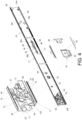
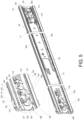
FIG. 5 andFIG. 6 are diagrams of a second rail at different views as an operating member is located at a first operated position according to the embodiment of the present invention, -
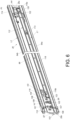
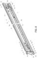
FIG. 7 andFIG. 8 are diagrams of the second rail at different views as the operating member is located at a second operated position according to the embodiment of the present invention, -
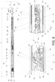
FIG. 9 is a diagram of the slide rail assembly in an extended state as the second rail is locked at an extended position according to the embodiment of the present invention, -
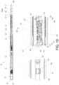
FIG. 10 is a diagram of the slide rail assembly in the extended state as the second rail is unlocked and movable along a retracting direction from the extended position according to the embodiment of the present invention, -
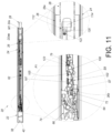
FIG. 11 is a diagram of the slide rail assembly as the second rail moves along the retracting direction according to the embodiment of the present invention, -
FIG. 12 is a diagram of the slide rail assembly as the second rail moves along the retracting direction to drive the second rail to abut against a first working member according to the embodiment of the present invention, -
FIG. 13 is a diagram of the slide rail assembly as the second rail moves along the retracting direction to drive the first working member to move to a second state by an abutment of the second rail and the first working member according to the embodiment of the present invention, -
FIG. 14 is a diagram of the slide rail assembly as the first rail is locked at a second predetermined position according to the embodiment of the present invention, -
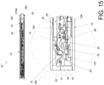
FIG. 15 is a diagram of the slide rail assembly as the third rail moves along the retracting direction to drive the third rail to abut against the second working member according to the embodiment of the present invention, -
FIG. 16 is a diagram of the slide rail assembly as the third rail moves along the retracting direction to drive the second working member to move to a fourth state by an abutment of the third rail and the second working member according to the embodiment of the present invention, and -
FIG. 17 is a partial section diagram of the slide rail assembly according to the embodiment of the present invention. - In the following detailed description of the preferred embodiments, reference is made to the accompanying drawings which form a part hereof, and in which is shown by way of illustration specific embodiments in which the invention may be practiced. In this regard, directional terminology, such as "top", "bottom", "left", "right", "front", "back", etc., is used with reference to the orientation of the Figure(s) being described. The members of the present invention can be positioned in a number of different orientations. As such, the directional terminology is used for purposes of illustration and is in no way limiting. Accordingly, the drawings and descriptions will be regarded as illustrative in nature and not as restrictive. Also, if not specified, the term "connect" is intended to mean either an indirect or direct mechanical connection. Thus, if a first device is connected to a second device, that connection may be through a direct mechanical connection, or through an indirect mechanical connection via other devices and connections.
- As shown in
FIG. 1 , aslide rail assembly 20 can be a multi-section rail assembly. In this embodiment, theslide rail assembly 20 can be a four-section rail assembly. Specifically, theslide rail assembly 20 includes a supportingframe 22, afirst rail 24, asecond rail 26 and athird rail 28. Thesecond rail 26 is movably mounted between thefirst rail 24 and thethird rail 28. For example, thefirst rail 24 can be an outer rail. Thesecond rail 26 can be a middle rail. Thethird rail 28 can be an inner rail. The supportingframe 22 can be a fourth rail, which is used as a reinforced rail or a fixed rail. The supportingframe 22, thefirst rail 24, thesecond rail 26 and thethird rail 28 can move relative to one another longitudinally. However, the present invention is not limited to this embodiment. For example, in another embodiment, the slide rail assembly can be a five-section rail assembly which includes an additional rail movably mounted on the supporting frame or the third rail. - More specifically, the supporting
frame 22 includes afront portion 22a and arear portion 22b. Thefirst rail 24 includes afront portion 24a and arear portion 24b. Thesecond rail 26 includes afront portion 26a and arear portion 26b. Thethird rail 28 includes afront portion 28a and arear portion 28b. - When the
slide rail assembly 20 is in an extended state, e.g., a fully extended state, thefirst rail 24 is located at a first predetermined position M1 relative to the supportingframe 22, thesecond rail 26 is located at an extended position E relative to thefirst rail 24, thethird rail 28 is located at an opened position K relative to thesecond rail 26 and a rear rail section r of thethird rail 28 is overlapped with a front rail section f of thefirst rail 24, such that the front rail section f of thefirst rail 24 and the rear rail section r of thethird rail 28 can support each other for enhancing a structural strength of theslide rail assembly 20. Preferably, when theslide rail assembly 20 is in the extended state, thefront portion 24a of thefirst rail 24 extends beyond thefront portion 22a of the supportingframe 22 along an opening direction D1, thefront portion 26a of thesecond rail 26 extends beyond thefront portion 24a of thefirst rail 24 along the opening direction D1, thefront portion 28a of thethird rail 28 extends beyond thefront portion 26a of thesecond rail 26 along the opening direction D1. More preferably, when theslide rail assembly 20 is in the extended state, thefront portion 26a of thesecond rail 26 extends beyond therear portion 28b of thethird rail 28 along the opening direction D1. - It should be noticed that, in this embodiment, a longitudinal direction of the rail, i.e., a length direction or a moving direction of rail, can be parallel to an X axis. A transverse direction of the rail, i.e., a lateral direction of the rail, can be parallel to a Y axis. A vertical direction of the rail, i.e., a height direction of the rail, can be parallel to a Z axis.
- As shown in
FIG. 2 andFIG. 3 , the supportingframe 22 further includes afirst wall 30a, asecond wall 30b and alongitudinal wall 32 connected between thefirst wall 30a and thesecond wall 30b of the supportingframe 22. Thefirst wall 30a, thesecond wall 30b and thelongitudinal wall 32 of the supportingframe 22 cooperatively define a supportingchannel 34 of the supportingframe 22. The supportingchannel 34 is configured to at least partially accommodate thefirst rail 24. A blockingstructure 36 and apositioning structure 38 are arranged on the supportingframe 22. - Preferably, the supporting
frame 22 further includes afront restraining feature 40 and arear restraining feature 42. Thefront restraining feature 40 and therear restraining feature 42 are configured to restrain a travel distance of thefirst rail 24. For example, thefront restraining feature 40 and therear restraining feature 42 can be protruding walls or protruding portions. However, the present invention is not limited thereto. Besides, the blockingstructure 36 and thepositioning structure 38 are located between thefront restraining feature 40 and therear restraining feature 42. In this embodiment, thefront restraining feature 40, the blockingstructure 36, thepositioning feature 38 and therear restraining feature 42 can be sequentially arranged on thelongitudinal wall 32 of the supportingframe 22 from front to rear. - Preferably, the
slide rail assembly 20 further includes an auxiliaryresilient seat 44 arranged on the supportingframe 22. The auxiliaryresilient seat 44 includes afirst fixing portion 46a, asecond fixing portion 46b and amiddle portion 48. Thefirst fixing portion 46a and thesecond fixing portion 46b are connected to thelongitudinal wall 32 of the supportingframe 22. Themiddle portion 48 is located between thefirst fixing portion 46a and thesecond fixing portion 46b. Themiddle portion 48 includes the blockingstructure 36, alongitudinal section 50 and a guidingsection 52. Thelongitudinal section 50 is located between the blockingstructure 36 and the guidingsection 52. For example, the blockingstructure 36 can be a blocking wall or an erecting wall, and the guidingsection 52 can be an inclined surface or an arc surface. However, the present invention is not limited thereto. - Preferably, for example, the
positioning feature 38 can be formed in a column shape or a protrusion. However, the present invention is not limited thereto. - As shown in
FIG. 2 andFIG. 4 , thefirst rail 24 is at least partially movably mounted inside the supportingchannel 34 of the supportingframe 22 and movable relative to the supportingframe 22. Thefirst rail 24 further includes afirst wall 54a, asecond wall 54b and alongitudinal wall 56 connected between thefirst wall 54a and thesecond wall 54b of thefirst rail 24. Thefirst wall 54a, thesecond wall 54b and thelongitudinal wall 56 of thefirst rail 24 cooperatively define afirst channel 58 of thefirst rail 24. Thefirst channel 58 is configured to at least partially accommodate thesecond rail 26. Thefirst rail 24 further includes a first side L1 and a second side L2 opposite to the first side L1. The first side L1 of thefirst rail 24 is located adjacent to the supportingframe 22. The second side L2 of thefirst rail 24 is located adjacent to thesecond rail 26. A blockingfeature 60 and apositioning feature 62 are arranged on thefirst rail 24. In this embodiment, a positioningmember 61 can be arranged on thefirst rail 24 and connected, e.g., fixedly connected, to the first side L1 of thefirst rail 24. The positioningmember 61 can include thepositioning feature 62. Thepositioning feature 62 can extend from the first side L1 of thefirst rail 24 to the second side L2 of thefirst rail 24 through anauxiliary hole 63 on thefirst rail 24. However, the present invention is not limited to this embodiment. For example, in another embodiment, the positioning feature can be a protrusion arranged on the second side of the first rail. - The
slide rail assembly 20 further includes a first workingmember 64 and a second workingmember 66. The first workingmember 64 is movably mounted on thefirst rail 24 and switchable between a first state S1 and a second state S2 relative to thefirst rail 24. The second workingmember 66 is movably mounted on thefirst rail 24 and switchable between a third state S3 and a fourth state S4 relative to thefirst rail 24. In this embodiment, the first workingmember 64 and the second workingmember 66 can be respectively pivotally connected to thelongitudinal wall 56 of thefirst rail 24 by a first pivotingmember 68 and asecond pivoting member 70 and located at the second side L2 of thefirst rail 24. However, the present invention is not limited to this embodiment. - Preferably, the
first rail 24 further includes anopening 69 communicated with the first side L1 and the second side L2 of thefirst rail 24. The first workingmember 64 includes a blockingportion 71 extending to the first side L1 of thefirst rail 24 through theopening 69. The blockingportion 71 is configured to cooperate with the blockingstructure 36 of the supportingframe 22. The second workingmember 66 includes apositioning portion 73 configured to cooperate with thepositioning structure 38 of the supportingframe 22. For example, the positioningportion 73 can be an engaging hook. However, the present invention is not limited thereto. - Preferably, the first working
member 64 further includes a releasingportion 75 configured to cooperate with thesecond rail 26. - Preferably, the
slide rail assembly 20 further includes a firstresilient member 72 and a secondresilient member 74 respectively configured to provide resilient forces to the first workingmember 64 and the second workingmember 66 to drive the first workingmember 64 and the second workingmember 66 to move to thefirst state S 1 and the third state S3 relative to thefirst rail 24. - Preferably, a first
auxiliary feature 76 and a supportingfeature 78 are arranged on thefirst rail 24. The blockingfeature 60, thepositioning feature 62, the firstauxiliary feature 76, the first workingmember 64 and the second workingmember 66 are sequentially arranged on thelongitudinal wall 56 of thefirst rail 24 from front to rear. - Preferably, the
first rail 24 further includes a front restrainingportion 80 and a rear restraining portion respectively configured to cooperate with thefront restraining feature 40 and therear restraining feature 42 of the supportingframe 22 for restraining a travel distance of thefirst rail 24 relative to the supportingframe 22. In this embodiment, the front restrainingportion 80 can be a protruding block located on thefirst side S 1 of thefirst rail 24 and facing toward thelongitudinal wall 32 of the supportingframe 22, and the front restrainingportion 80 can stretch into alongitudinal space 82 of thelongitudinal wall 32 of the supportingframe 22, e.g., a longitudinal slot of thelongitudinal wall 32 of the supportingframe 22, so as to be located at a position corresponding to thefront restraining feature 40. The rear restraining portion can be therear portion 24b. However, the present invention is not limited to this embodiment. - Preferably, the
slide rail assembly 20 further includes aresilient seat 84 arranged on thefirst rail 24. Theresilient seat 84 includes a first connectingportion 86a, a second connectingportion 86b and a supportingstructure 88. The first connectingportion 86a and the second connectingportion 86b are connected to thelongitudinal wall 56 of thefirst rail 24. The supportingstructure 88 is located between the first connectingportion 86a and the second connectingportion 86b. The supportingstructure 88 includes the blockingfeature 60, alongitudinal portion 90 and a guidingportion 92. Thelongitudinal portion 90 is located between the blockingfeature 60 and the guidingportion 92. For example, the blockingfeature 60 can be a blocking wall or an erecting wall, and the guidingportion 92 can be an inclined surface or an arc surface. However, the present invention is not limited thereto. - As shown in
FIG. 2 ,FIG. 5 andFIG. 6 , thesecond rail 26 is movable relative to thefirst rail 24. Thesecond rail 26 further includes afirst wall 94a, asecond wall 94b and alongitudinal wall 96 connected between thefirst wall 94a and thesecond wall 94b of thesecond rail 26. Thefirst wall 94a, thesecond wall 94b and thelongitudinal wall 96 of thesecond rail 26 cooperatively define asecond channel 98 of thesecond rail 26. Thesecond channel 98 is configured to at least partially accommodate thethird rail 28. Thesecond rail 26 further includes a first side L1 and a second side L2 opposite to the first side L1. The first side L1 of thesecond rail 26 is located adjacent to thefirst rail 24. The second side L2 of thesecond rail 26 is located adjacent to thethird rail 28. - Preferably, the
slide rail assembly 20 further includes a third workingmember 100 and a fourth workingmember 102. The third workingmember 100 is movably mounted on thesecond rail 26 and switchable between a fifth state S5 and a sixth state S6 relative to thesecond rail 26. The fourth workingmember 102 is movably mounted on thesecond rail 26 and switchable between a seventh state S7 and a eighth state S8 relative to thesecond rail 26. In this embodiment, the third workingmember 100 and the fourth workingmember 102 can be respectively pivotally connected to thelongitudinal wall 96 of thesecond rail 26 by afirst shaft 104 and asecond shaft 106 and located at the second side L2 of thesecond rail 26. However, the present invention is not limited to this embodiment. - Preferably, the
slide rail assembly 20 further includes a firstresilient feature 105 and a secondresilient feature 107 respectively configured to provide resilient forces to the third workingmember 100 and the fourth workingmember 102 for driving the third workingmember 100 and the fourth workingmember 102 to move to the fifth state S5 and the seventh state S7 relative to thesecond rail 26. - Preferably, the
second rail 26 further includes at least one hole arranged on thelongitudinal wall 96 of thesecond rail 26 and communicated with the first side L1 and the second side L2 of thesecond rail 26. In this embodiment, thesecond rail 26 can include a first hole H1 and a second hole H2. Furthermore, the third workingmember 100 includes afirst blocking section 108 stretching into the first hole H1. Thefirst blocking section 108 faces toward thelongitudinal wall 56 of thefirst rail 24 and is configured to cooperate with the blockingfeature 60 or thepositioning feature 62 of thefirst rail 24. The fourth workingmember 102 includes asecond blocking section 110 stretching into the second hole H2. Thesecond blocking section 110 faces toward thelongitudinal wall 56 of thefirst rail 24 and is configured to cooperate with thepositioning feature 62 of thefirst rail 24. However, the present invention is not limited to this embodiment. For example, in another embodiment, there can be only one hole arranged on the longitudinal wall of the second rail for the first blocking section and the second blocking section to pass therethrough. - Preferably, the
slide rail assembly 20 further includes an operatingmember 112 movably mounted on thesecond rail 26 and configured to operate one of the third workingmember 100 and the fourth workingmember 102. - Preferably, the operating
member 112 is mounted on thelongitudinal wall 96 of thesecond rail 26 and located at the first side L1 of thesecond rail 26. The operatingmember 112 includes an operatingportion 114, a drivingportion 116 and an extendingportion 118 connected between the operatingportion 114 and the drivingportion 116. The operatingportion 114 is connected to afront end 118a of the extendingportion 118. The operatingportion 114 is located adjacent to thefront portion 26a of thesecond rail 26. The drivingportion 116 is connected to arear end 118b of the extendingportion 118. The drivingportion 116 is located adjacent to therear portion 26b of thesecond rail 26. Besides, the third workingmember 100 and the fourth workingmember 102 are located adjacent to therear portion 26b of thesecond rail 26. - Preferably, the
second rail 26 further includes a third hole H3 arranged on thelongitudinal wall 96 of thesecond rail 26. The drivingportion 116 of the operatingmember 112 extends from the first side L1 to the second side L2 of thesecond rail 26 through the third hole H3 and is located adjacent to the third workingmember 100. - Preferably, the
second rail 26 further includes a fourth hole H4 arranged on thelongitudinal wall 96 of thesecond rail 26. The operatingportion 114 of the operatingmember 112 is exposed on the second side L2 of thesecond rail 26 via the fourth hole H4. - Preferably, the
second rail 26 and the operatingmember 112 have corresponding restraining features cooperating with each other for restraining a travel distance of the operatingmember 112 relative to thesecond rail 26. In this embodiment, at least oneelongated hole 120 can be arranged on the extendingportion 118 of the operatingmember 112. Thesecond rail 26 can further include at least one connectingmember 122 connected to thelongitudinal wall 96 of thesecond rail 26 and passing through a portion of the at least oneelongated hole 120. Furthermore, thesecond rail 26 can further include at least one extendinghole 111. At least one connectingsection 113 can be arranged on the extendingportion 118 of the operatingmember 112 and passes through a portion of the at least one extendinghole 111. The travel distance of the operatingmember 112 relative to thesecond rail 26 can be restrained by a cooperation of the at least oneelongated hole 120 and the at least one connectingmember 122 and a cooperation of the at least one extendinghole 111 and the at least one connectingsection 113. However, the present invention is not limited to this embodiment. For example, in another embodiment, there can be only the elongated hole and the at least one connecting member cooperating with each other. Alternatively, in another embodiment, there can be only the extending hole and the connecting section cooperating with each other. - Preferably, as shown in
FIG. 2 andFIG. 6 , a secondauxiliary feature 123 is arranged on the operatingmember 112 and configured to cooperate with the firstauxiliary feature 76 of thefirst rail 24. For example, the firstauxiliary feature 76 and the secondauxiliary feature 123 can be protrusions. However, the present invention is not limited thereto. Besides, as shown inFIG. 6 , the secondauxiliary feature 123 is arranged adjacent to therear end 118b of the extendingportion 118 of the operatingmember 112, and the secondauxiliary feature 123 and the drivingportion 116 are located at two opposite sides of the extendingportion 118 of the operatingmember 112. - When the operating
member 112 is located at a first operated position P1 relative to thesecond rail 26 as shown inFIG. 5 andFIG. 6 , the third workingmember 100 and the fourth workingmember 102 are respectively in the fifth state S3 and the seventh state S7 relative to thesecond rail 26. - Preferably, as shown in
FIG. 5 , the third workingmember 100 further includes an abuttingportion 124 and anactuating portion 126. Thefirst shaft 104 is located between the abuttingportion 124 and theactuating portion 126. The abuttingportion 124 is located at a position corresponding to the drivingportion 116 of the operatingmember 112 and for abutting against the drivingportion 116 of the operatingmember 112. Thefirst blocking section 108 is located adjacent to theactuating portion 126. Thefirst blocking section 108 extends to the first side L1 of thesecond rail 26. The firstresilient feature 105 is configured to provide the resilient force to the third workingmember 100 for retaining the third workingmember 100 in the fifth state S5. - Preferably, as shown in
FIG. 5 , the fourth workingmember 102 includes anabutting section 128 and anactuating section 130. Thesecond shaft 106 is located between theabutting section 128 and theactuating section 130. Thesecond blocking section 110 is located adjacent to theabutting section 128. Thesecond blocking section 110 extends to the first side L1 of thesecond rail 26. The secondresilient feature 107 is configured to provide the resilient force to the fourth workingmember 102 for retaining the fourth workingmember 102 in the seventh state S7. - As shown in
FIG. 5 to FIG. 8 , the user can apply a force F onto the operatingmember 112, e.g., the operatingportion 114 of the operatingmember 112, to drive the operatingmember 112 to move relative to thesecond rail 26 from the first operated position P1 to a second operated position P2. During the aforementioned process, the operatingmember 112 drives the third workingmember 100 to move, e.g., pivot, relative to thesecond rail 26 from the fifth state S5 as shown inFIG. 5 andFIG. 6 to the sixth state S6 as shown inFIG. 7 andFIG. 8 by an abutment of the drivingportion 116 and the abuttingportion 124 of the third workingmember 100. Preferably, when the third workingmember 100 moves from the fifth state S5 as shown inFIG. 5 andFIG. 6 to the sixth state S6 as shown inFIG. 7 andFIG. 8 , the third workingmember 100 drives the fourth workingmember 102 to move, e.g., pivot, relative to thesecond rail 26 from the seventh state S7 as shown inFIG. 5 andFIG. 6 to the eighth state S8 as shown inFIG. 7 andFIG. 8 by an abutment of theactuating portion 126 and theabutting section 128 of the fourth workingmember 102. In other words, in this embodiment, the third workingmember 100 and the fourth workingmember 102 are configured to move synchronously, and the third workingmember 100 and the fourth workingmember 102 are respectively configured to be driven by the operatingmember 112 and the third workingmember 100. However, the present invention is not limited to this embodiment. For example, in another embodiment, the third working member and the fourth working member are configured to move synchronously, and the third working member and the fourth working member are respectively configured to be driven by the fourth working member and the operating member. Alternatively, the third working member and the fourth working member are configured to move synchronously, and the third working member and the fourth working member are configured to be driven by two driving portions of the operating member respectively. Alternatively, the slide rail assembly further includes an auxiliary operating member, and the third working member and the fourth working member are configured to be driven by the operating member and the auxiliary operating member respectively and to move asynchronously. - Preferably, as shown in
FIG. 7 andFIG. 8 , when the operatingmember 112 is located at the second operated position P2, the third workingmember 100 and the fourth workingmember 102 are respectively retained in the sixth state S6 and the eighth state S8 by an abutment of the operatingmember 112 and the third workingmember 100 and an abutment of the third workingmember 100 and the fourth workingmember 102. - As shown in
FIG. 9 , theslide rail assembly 20 is used in a limited environment and located in the extended state. As mentioned above, when theslide rail assembly 20 is located in the extended state, thefirst rail 24 is located at the first predetermined position M1 relative to the supportingframe 22, thesecond rail 26 is located at the extended position E relative to thefirst rail 24, and thethird rail 28 is located at the opened position K1 relative to thesecond rail 26. At this moment, theslide rail assembly 20 has a first length 11, and afront portion 28a of thethird rail 28 is spaced apart from anobject 132, e.g., a door or an obstruction, by a first distance X1. The first distance X1 is too short to detach thethird rail 28 from thesecond rail 26, e.g., thesecond channel 98 of thesecond rail 26, along the opening direction D1. - Specifically, when the
first rail 24 is located at the first predetermined position M1 relative to the supportingframe 22 as shown inFIG. 9 , the blockingstructure 36 of the supportingframe 22 blocks the blockingportion 71 of the first workingmember 64 in the first state S1 for preventing thefirst rail 24 from moving along a retracting direction D2 from the first predetermined position M1. Besides, at this moment, the operatingmember 112 is located at the first operated position P1, similarly toFIG. 5 andFIG. 6 . Therefore, when thesecond rail 26 is located at the extended position E relative to thefirst rail 24, the blockingfeature 60 of thefirst rail 24 blocks thefirst blocking section 108 of the third workingmember 100 in the fifth state S5 for preventing thesecond rail 26 from moving along the retracting direction D2 from the extended position E, and thesecond blocking section 110 of the fourth workingmember 102 is located adjacent to the guidingportion 92 of theresilient seat 84 of thefirst rail 24. It should be noticed that when the third workingmember 100 and the fourth workingmember 102 are respectively in the fifth state S5 and the seventh state S7, thefirst blocking section 108 of the third workingmember 100 and thesecond blocking section 110 of the fourth workingmember 102 are located at positions where thefirst blocking section 108 of the third workingmember 100 and thesecond blocking section 110 of the fourth workingmember 102 are aligned with thepositioning feature 62 of thefirst rail 24 along the retracting direction D2 or theopening direction D 1. - As shown in
FIG. 10 , when the user applies the force F onto the operatingmember 112, e.g., the operatingportion 114 of the operatingmember 112, to drive the operatingmember 112 to move from the first operated position P1 to the second operated position P2, the operatingmember 112 drives the third workingmember 100 by the drivingportion 116 to move from the fifth state S5 to the sixth state S6, such that the blockingfeature 60 cannot block thefirst blocking section 108 of the third workingmember 100 in the sixth state S6 for allowing thesecond rail 26 to move relative to thefirst rail 24 along the retracting direction D2 from the extended position E. - Furthermore, when the operating
member 112 is located at the second operated position P2 as shown inFIG. 10 , the third workingmember 100 and the fourth workingmember 102 are respectively retained in the sixth state S6 and the eighth state S8, such that the firstresilient feature 105 and the secondresilient feature 107 are resiliently deformed to generate the resilient forces, similarly toFIG. 7 . Besides, when the third workingmember 100 and the fourth workingmember 102 are respectively in the sixth state S6 and the eighth state S8, thefirst blocking section 108 of the third workingmember 100 and thesecond blocking section 110 of the fourth workingmember 102 are dislocated from the positions where thefirst blocking section 108 of the third workingmember 100 and thesecond blocking section 110 of the fourth workingmember 102 are aligned with thepositioning feature 62 of thefirst rail 24 along the retracting direction D2 or the opening direction D1. Moreover, as shown inFIG. 10 , when thesecond rail 26 is located at the extended position E relative to thefirst rail 24, the secondauxiliary feature 123 of the operatingmember 112 is separated away from the firstauxiliary feature 76 of thefirst rail 24 by a distance. - Preferably, as shown in
FIG. 10 andFIG. 11 , thepositioning feature 62 includes afront portion 62a and arear portion 62b. Thefirst blocking section 108 of the third workingmember 100 and therear portion 62b of thepositioning feature 62 respectively include afirst guiding feature 109 and asecond guiding feature 115. For example, thefirst guiding feature 109 and asecond guiding feature 115 can be inclined surfaces or arc surfaces. - When the
second rail 26 moves along the retracting direction D2 for a predetermined distance, e.g., to a position as shown inFIG. 11 , the firstauxiliary feature 76 of thefirst rail 24 abuts against the secondauxiliary feature 123 of the operatingmember 112 to drive the operatingmember 112 to move from the second operated position P2 to the first operated position P1, such that the third workingmember 100 is driven to move from the sixth state S6 to the fifth state S5 by the firstresilient feature 105, and the fourth workingmember 102 is driven to move from the eighth state S8 to the seventh state S7 by the secondresilient feature 107. Preferably, one of the firstauxiliary feature 76 and the secondauxiliary feature 123 can include another guiding surface, e.g., an inclined surface or an arc surface, facing toward the other one of the firstauxiliary feature 76 and the secondauxiliary feature 123 to facilitate the secondauxiliary feature 123 to pass over the firstauxiliary feature 76 along the retracting direction D2 when thesecond rail 26 moves relative to thefirst rail 24 along the retracting direction D2. - When the
first rail 24 is located at the first predetermined position M1 relative to the supportingframe 22, thesecond rail 26 can be moved along the retracting direction D2 from the extended position E to abut against the releasingportion 75 of the first workingmember 64 by therear portion 26b for driving the first workingmember 64 to move from the first state S1 as shown inFIG. 12 to the second state S2 as shown inFIG. 13 , such that the blockingstructure 36 of the supportingframe 22 does not block the blockingportion 71 of the first working member in the second state S2 for allowing thefirst rail 24 to move along the retracting direction D2 from the first predetermined position M1 to a second predetermined position M2. - As shown in
FIG. 14 , when thefirst rail 24 is located at the second predetermined position M2 relative to the supportingframe 22, the second workingmember 66, e.g., the positioningportion 73 of the second workingmember 66, in the third state S3 can engage with thepositioning structure 38 of the supportingframe 22 for retaining thefirst rail 24 at the second predetermined position M2, so as to prevent thefirst rail 24 from moving along the opening direction D1 or the retracting direction D2 from the second predetermined position M2. When thefirst rail 24 is located at the second predetermined position M2, theslide rail assembly 20 has a second length J2 less than the first length 11, such that thefront portion 28a of thethird rail 28 is spaced apart from theobject 132 by a second distance X2 greater than the first distance X1, which facilitates detachment of thethird rail 28 from thesecond rail 26, e.g., thesecond channel 98 of thesecond rail 26, along the opening direction D1. - Preferably, when the
first rail 24 is located at the second predetermined position M2 relative to the supportingframe 22, therear restraining feature 42 of the supportingframe 22 can abut against therear portion 24b of thefirst rail 24 for stopping thefirst rail 24. Thefirst rail 24 further includes a restrainingmember 133 configured to abut against the rear porting 26b of thesecond rail 26 for stopping thesecond rail 26. When the restrainingmember 133 abuts against the rear porting 26b of thesecond rail 26, thesecond rail 26 is fully folded relative to thefirst rail 24. - As shown in
FIG. 15 andFIG. 16 , thethird rail 28 further includes afirst wall 29a, asecond wall 29b and alongitudinal wall 31 connected between thefirst wall 29a and thesecond wall 29b of thethird rail 28. When thesecond rail 26 is located at the second predetermined position M2 relative to the supportingframe 22 and thesecond rail 26 is fully folded relative to thefirst rail 24, thethird rail 28 is movable relative to thefirst rail 24 along the retracting direction D2 to a retracted position R. During a movement of thethird rail 28 relative to thefirst rail 24 along the retracting direction D2 to the retracted position R, a portion of thethird rail 28, e.g., therear portion 28 of thethird rail 28, can abut against anauxiliary portion 134, which is shown inFIG. 15 , of the second workingmember 66 in the third state S3 for driving the second workingmember 66 to pivot by an angle to move from the third state S3 as shown inFIG. 15 to the fourth state S4 as shown inFIG. 16 . When thethird rail 28 is located at the retracted position R relative to thefirst rail 24, thesecond wall 29b of thethird rail 28 supports the second workingmember 66 for retaining the second workingmember 66 in the fourth state S4, such that thepositioning portion 73 of the second workingmember 66 is not engaged with thepositioning structure 38 of the supportingframe 22 for allowing thefirst rail 24 to move along the opening direction D1 from the second predetermined position M2. - Preferably, as shown in
FIG. 16 , when thethird rail 28 is located at the retracted position R relative to thefirst rail 24, the supportingfeature 78 of thefirst rail 24 is configured to support a portion of thesecond wall 29b of thethird rail 28 adjacent to a rear rail section of thethird rail 28 for enhancing a structural strength of theslide rail assembly 20. - Preferably, as shown in
FIG. 16 , thethird rail 28 further includes afirst synchronizing feature 136 and asecond synchronizing feature 138. During a movement of thethird rail 28 along the opening direction D1 from the retracted position R, thefirst synchronizing feature 136 of thethird rail 28 can abut against a firstcorresponding feature 140 of the first workingmember 64 for driving thethird rail 28 and thefirst rail 24 to move synchronously along the opening direction D1 until thefirst rail 24 moves to the first predetermined position M1. Besides, thesecond synchronizing feature 138 of thethird rail 28 can abut against a secondcorresponding feature 142 of the third workingmember 100 for driving thethird rail 28 and thesecond rail 26 to be moved synchronously along the opening direction D1 until thesecond rail 26 moves to the extended position E. - As shown in
FIG. 17 , thefirst wall 30a, thesecond wall 30b and thelongitudinal wall 32 of the supportingframe 22 cooperatively define the supportingchannel 34 of the supportingframe 22. Each of thefirst wall 30a and thesecond wall 30b has a first supportingportion 144 and a second supportingportion 146 bent from the first supportingportion 144. Each of thelongitudinal wall 32 and the first supportingportions 144 of the supportingframe 22 has a first predetermined thickness T1. Each of the second supportingportions 146 has a second predetermined thickness T2 less than the first predetermined thickness T1. The first predetermined thickness T1 of the first supportingportion 144 extends along the Z axis. The first predetermined thickness T1 of thelongitudinal wall 32 and the second predetermined thickness T2 of the second supportingportion 146 extend along the Y axis. - Preferably, each of the second supporting
portions 146 of the supportingframe 22 includes afirst surface 148. Thelongitudinal wall 31 of thethird rail 28 includes asecond surface 150. Thefirst surfaces 148 and thesecond surface 150 are not coplanar. For example, thefirst surfaces 148 can be located on a first horizontal plane V1, and thesecond surface 150 can be located on a second horizontal plane V2 protruding out of the first horizontal plane V1, which facilitates mounting a carried object, which is not shown in the figures, on thethird rail 28. In other words, thefirst surfaces 148 of the supportingframe 22 do not cause any interference with a mounting operation of the carried object on thethird rail 28. - The
first wall 54a, thesecond wall 54b and thelongitudinal wall 56 of thefirst rail 24 cooperatively define thefirst channel 58 of thefirst rail 24. Thefirst wall 30a, thesecond wall 30b and thelongitudinal wall 32 of the supportingframe 22 are configured to at least partially cover thefirst wall 54a, thesecond wall 54b and thelongitudinal wall 56 of thefirst rail 24 to support thefirst rail 24 for enhancing a supporting capability of thefirst rail 24. - Preferably, the
first wall 94a, thesecond wall 94b and thelongitudinal wall 96 of thesecond rail 26 cooperatively define thesecond channel 98 of thesecond rail 26. - Preferably, the
slide rail assembly 20 further includes a first facilitatingdevice 152 movably mounted between thefirst rail 24 and thesecond rail 26 for ensuring a smooth sliding movement of thesecond rail 26 relative to thefirst rail 24. The first facilitatingdevice 152 at least includes afirst roller 154 and asecond roller 156. Thefirst roller 154 is supported between thefirst wall 54a of thefirst rail 24 and thefirst wall 94a of thesecond rail 26. Thesecond roller 156 is supported between thesecond wall 54b of thefirst rail 24 and thesecond wall 94b of thesecond rail 26. - Preferably, the
slide rail assembly 20 further includes a second facilitatingdevice 158 movably mounted between thesecond rail 26 and thethird rail 28 for ensuring a smooth sliding movement of thethird rail 28 relative to thesecond rail 26. The second facilitatingdevice 158 at least includes athird roller 160 and afourth roller 162. Thethird roller 160 is supported between thefirst wall 94a of thesecond rail 26 and thefirst wall 29a of thethird rail 28. Thefourth roller 162 is supported between thesecond wall 94b of thesecond rail 26 and thesecond wall 29b of thethird rail 28. - From the above, the
slide rail assembly 20 of the present invention has the following feature of that when theslide rail assembly 20 is in the extended state, thefirst rail 24 is located at the first predetermined position M1 relative to the supportingframe 22, thesecond rail 26 is located at the extended position E relative to thefirst rail 24, and thethird rail 28 is located at the opened position K relative to thesecond rail 26 and the rear rail section r of thethird rail 28 is overlapped with the front rail section f of thefirst rail 24, such that the front rail section f of thefirst rail 24 and the rear rail section r of thethird rail 28 can support each other for enhancing the structural strength of theslide rail assembly 20. - Those skilled in the art will readily observe that numerous modifications and alterations of the device and method may be made while retaining the teachings of the invention. Accordingly, the above disclosure should be construed as limited only by the metes and bounds of the appended claims.
Claims (15)
- A slide rail assembly (20) comprising:a supporting frame (22);a first rail (24) movable relative to the supporting frame (22);a second rail (26) movable relative to the first rail (24); anda third rail (28) movable relative to the second rail (26);characterized in that:
when the slide rail assembly (20) is in an extended state, the first rail (24) is located at a first predetermined position (M1) relative to the supporting frame (22), the second rail (26) is located at an extended position (E) relative to the first rail (24), the third rail (28) is located at an opened position (K) relative to the second rail (26) and a rear rail section (r) of the third rail (28) is overlapped with a front rail section (f) of the first rail (24). - The slide rail assembly (20) of claim 1, characterized in that each of the supporting frame (22), the first rail (24), the second rail (26) and the third rail (28) comprises a front portion (22a, 24a, 26a, 28a) and a rear portion (22b, 24b, 26b, 28b), the supporting frame (22) further comprises a supporting channel (34) configured to at least partially accommodate the first rail (24), the first rail (24) further comprises a first channel (58) configured to at least partially accommodate the second rail (26), and the second rail (26) further comprises a second channel (98) configured to at least partially accommodate the third rail (28).
- The slide rail assembly (20) of claim 2, characterized in that when the slide rail assembly (20) is in the extended state, the front portion (24a) of the first rail (24) extends beyond the front portion (22a) of the supporting frame (22), the front portion (26a) of the second rail (26) extends beyond the front portion (24a) of the first rail (24), and the front portion (28a) of the third rail (28) extends beyond the front portion (26a) of the second rail (26).
- The slide rail assembly (20) of claim 3, characterized in that when the slide rail assembly (20) is in the extended state, the front portion (26a) of the second rail (26) extends beyond the rear portion (28b) of the third rail (28).
- The slide rail assembly (20) of any of claims 2 to 4, characterized in that the supporting frame (22) further comprises a first wall (30a), a second wall (30b) and a longitudinal wall (32) connected between the first wall (30a) and the second wall (30b) of the supporting frame (22), and the supporting channel (34) is defined by the first wall (30a), the second wall (30b) and the longitudinal wall (32) of the supporting frame (22) cooperatively.
- The slide rail assembly (20) of claim 5, characterized in that each of the first wall (30a) and the second wall (30b) of the supporting frame (22) comprises a first supporting portion (144) and a second supporting portion (146) bent relative to the first supporting portion (144), each of the longitudinal wall (32) of the supporting frame (22) and the first supporting portion (144) has a first predetermined thickness (T1), and the second supporting portion (146) has a second predetermined thickness (T2) less than the first predetermined thickness (T1).
- The slide rail assembly (20) of claim 6, characterized in that the first rail (24) further comprises a first wall (54a), a second wall (54b) and a longitudinal wall (56) connected between the first wall (54a) and the second wall (54b) of the first rail (24), the first channel (58) is defined by the first wall (54a), the second wall (54b) and the longitudinal wall (56) of the first rail (24) cooperatively, and the first wall (54a), the second wall (54b) and the longitudinal wall (56) of the supporting frame (22) are configured to at least partially cover the first wall (54a), the second wall (54b) and the longitudinal wall (56) of the first rail (24).
- The slide rail assembly (20) of claim 7, characterized in that the second rail (26) further comprises a first wall (94a), a second wall (94b) and a longitudinal wall (96) connected between the first wall (94a) and the second wall (94b) of the second rail (26), the second channel (98) is defined by the first wall (94a), the second wall (94b) and the longitudinal wall (96) of the second rail (26) cooperatively, and the third rail (28) further comprises a first wall (94a), a second wall (94b) and a longitudinal wall (96) connected between the first wall (94a) and the second wall (94b) of the third rail (28).
- The slide rail assembly (20) of claim 8, characterized in that the second supporting portion (146) comprises a first surface (148), the longitudinal wall of the third rail (28) comprises a second surface (150), and the first surface (148) and the second surface (150) are not coplanar.
- The slide rail assembly (20) of any of claims 1 to 9, characterized in that a blocking structure (36) and a positioning structure (38) are arranged on the supporting frame (22), a blocking feature (60) and a positioning feature (62) are arranged on the first rail (24), the second rail (26) is movably mounted between the first rail (24) and the third rail (28), the slide rail assembly (20) further comprises a first working member (64) and a second working member (66), the first working member (64) is movably mounted to the first rail (24) and switchable between a first state (S1) and a second state (S2), the second working member (66) is movably mounted to the first rail (24) and switchable between a third state (S3) and a fourth state (S4), when the first rail (24) is located at the first predetermined position (M1) relative to the supporting frame (22), the blocking structure (36) blocks the first working member (64) in the first state (S1) for preventing the first rail (24) from moving along a retracting direction (D2) from the first predetermined position (M1), and when the first rail (24) is located at a second predetermined position (M2) relative to the supporting frame (22), the second working member (66) in the third state (S3) engages with the positioning structure (38) for preventing the first rail (24) from moving along an opening direction (D1) from the second predetermined position (M2).
- The slide rail assembly (20) of claim 10, characterized in that the first working member (64) and the second working member (66) are pivotally connected to the first rail (24), and the slide rail assembly (20) further comprises a first resilient member (72) and a second resilient member (74) respectively configured to provide resilient forces to the first working member (64) and the second working member (66).
- The slide rail assembly (20) of any of claims 10 to 11, characterized in that when the first rail (24) is located at the first predetermined position (M1) relative to the supporting frame (22) and the first working member (64) moves from the first state (S1) to the second state (S2), the blocking structure (36) does not block the first working member (64) in the second state (S2) for allowing the first rail (24) to move along the retracting direction (D2) from the first predetermined position (M1) to the second predetermined position (M2).
- The slide rail assembly (20) of any of claims 10 to 12, characterized in that when the first rail (24) is located at the second predetermined position (M2) relative to the supporting frame (22) and the third rail (28) is located at a retracted position (R) relative to the first rail (24), the third rail (28) is configured to support the second working member (66), such that the second working member (66) is retained in the fourth state (S4) and does not engage with the positioning structure (38) for allowing the first rail (24) to move along the opening direction (D1) from the second predetermined position (M2).
- The slide rail assembly (20) of claim 13, characterized in that a supporting feature (78) is arranged on the first rail (24) and configured to support the third rail (28) when the third rail (28) is located at the retracted position (R) relative to the first rail (24).
- The slide rail assembly (20) of any of claims 13 to 14, characterized in that the third rail (28) comprises a synchronizing feature (136), and the synchronizing feature (136) abuts against the first working member (64) for allowing the third rail (28) and the first rail (24) to move along the opening direction (D1) synchronously during a movement of the third rail (28) along the opening direction (D1) from the retracted position (R).
Applications Claiming Priority (1)
| Application Number | Priority Date | Filing Date | Title |
|---|---|---|---|
| TW111150804A TWI826218B (en) | 2022-12-28 | 2022-12-28 | Slide rail assembly |
Publications (2)
| Publication Number | Publication Date |
|---|---|
| EP4393349A1 true EP4393349A1 (en) | 2024-07-03 |
| EP4393349B1 EP4393349B1 (en) | 2025-09-10 |
Family
ID=86732512
Family Applications (1)
| Application Number | Title | Priority Date | Filing Date |
|---|---|---|---|
| EP23178105.5A Active EP4393349B1 (en) | 2022-12-28 | 2023-06-07 | Slide rail assembly |
Country Status (4)
| Country | Link |
|---|---|
| US (1) | US12220055B2 (en) |
| EP (1) | EP4393349B1 (en) |
| JP (1) | JP7507290B1 (en) |
| TW (1) | TWI826218B (en) |
Families Citing this family (2)
| Publication number | Priority date | Publication date | Assignee | Title |
|---|---|---|---|---|
| TWI849694B (en) * | 2023-01-13 | 2024-07-21 | 川湖科技股份有限公司 | Slide rail assembly |
| TWI877012B (en) * | 2024-05-24 | 2025-03-11 | 南俊國際股份有限公司 | Slide rail assembly |
Citations (3)
| Publication number | Priority date | Publication date | Assignee | Title |
|---|---|---|---|---|
| US20120087604A1 (en) | 2010-10-12 | 2012-04-12 | Hon Hai Precision Industry Co., Ltd. | Slide rail for rack sever |
| TWI723808B (en) * | 2019-09-23 | 2021-04-01 | 南俊國際股份有限公司 | Improved middle rail structure of a slide rail |
| US20210120952A1 (en) * | 2019-10-29 | 2021-04-29 | Jonathan Manufacturing Corporation Dba Jonathan Engineered Solutions | Slide assembly |
Family Cites Families (29)
| Publication number | Priority date | Publication date | Assignee | Title |
|---|---|---|---|---|
| TW582693U (en) * | 2003-05-14 | 2004-04-01 | Hon Hai Prec Ind Co Ltd | Rail assembly |
| US7413269B2 (en) * | 2004-08-04 | 2008-08-19 | King Slide Works Co., Ltd. | Synchronous system for a three-stage ball bearing slide |
| TW201320926A (en) * | 2011-11-18 | 2013-06-01 | Chong-Yao Chen | Pull synchronizing device and guiding rack and sliding rail unit thereof |
| US9258923B2 (en) * | 2014-01-07 | 2016-02-09 | King Slide Works Co., Ltd. | Adjustable bracket assembly and slide assembly |
| US9723922B2 (en) * | 2014-11-07 | 2017-08-08 | Hardware Resources, Inc. | Slidable cabinet pullout apparatus and method of use |
| US9861197B2 (en) * | 2015-02-13 | 2018-01-09 | King Slide Works Co., Ltd. | Slide rail assembly |
| US9635942B2 (en) * | 2015-03-26 | 2017-05-02 | King Slide Works Co., Ltd. | Slide rail assembly |
| CN105962664B (en) * | 2016-01-12 | 2018-06-15 | 林旭文 | Furniture slide rail |
| TWI568382B (en) * | 2016-01-22 | 2017-02-01 | 川湖科技股份有限公司 | Slide rail assembly and operation method thereof |
| KR102496370B1 (en) * | 2016-03-07 | 2023-02-06 | 삼성전자주식회사 | Rail device and refrigerator having the smae |
| TWI584761B (en) * | 2016-09-13 | 2017-06-01 | 川湖科技股份有限公司 | Slide rail assembly |
| US10213017B2 (en) * | 2016-10-05 | 2019-02-26 | King Slide Works Co., Ltd. | Slide rail assembly |
| TWI600393B (en) | 2016-11-22 | 2017-10-01 | 川湖科技股份有限公司 | Supporting device for rail member |
| TWI618507B (en) | 2017-04-28 | 2018-03-21 | 川湖科技股份有限公司 | Slide rail assembly |
| TWI646923B (en) * | 2017-11-27 | 2019-01-11 | 川湖科技股份有限公司 | Slide rail assembly and rail assembly |
| TWI645807B (en) * | 2017-12-28 | 2019-01-01 | 川湖科技股份有限公司 | Slide rail assembly |
| TWI693042B (en) | 2018-07-19 | 2020-05-11 | 川湖科技股份有限公司 | Slide rail mechanism and bracket device thereof |
| TWI700056B (en) * | 2019-06-12 | 2020-08-01 | 川湖科技股份有限公司 | Slide rail assembly |
| TWI721493B (en) * | 2019-07-12 | 2021-03-11 | 川湖科技股份有限公司 | Slide rail assembly |
| TWI706751B (en) * | 2019-08-14 | 2020-10-11 | 川湖科技股份有限公司 | Slide rail assembly |
| TWI700979B (en) | 2019-08-28 | 2020-08-01 | 川湖科技股份有限公司 | Slide rail assembly and bracket mechanism thereof |
| TWI704889B (en) * | 2019-10-28 | 2020-09-21 | 川湖科技股份有限公司 | Slide rail assembly |
| CN112890473B (en) * | 2019-11-19 | 2022-07-12 | Topsco有限公司 | Drawer slide device with retainer restored to correct position |
| TWI706750B (en) | 2019-11-19 | 2020-10-11 | 川湖科技股份有限公司 | Slide rail mechanism |
| US11122894B1 (en) * | 2020-02-28 | 2021-09-21 | TPA Motion, LLC | Systems, methods, and apparatuses for load bearing slides |
| TWI748581B (en) * | 2020-07-29 | 2021-12-01 | 振躍精密滑軌股份有限公司 | Slide rail structure with double middle rails |
| TWI742835B (en) * | 2020-09-01 | 2021-10-11 | 川湖科技股份有限公司 | Slide rail assembly and slide rail kit thereof |
| TWI737555B (en) | 2020-12-22 | 2021-08-21 | 川湖科技股份有限公司 | Slide rail assembly and slide rail kit thereof |
| TWI738613B (en) * | 2021-02-01 | 2021-09-01 | 川湖科技股份有限公司 | Slide rail assembly |
-
2022
- 2022-12-28 TW TW111150804A patent/TWI826218B/en active
-
2023
- 2023-05-17 US US18/198,293 patent/US12220055B2/en active Active
- 2023-06-07 EP EP23178105.5A patent/EP4393349B1/en active Active
- 2023-06-27 JP JP2023105351A patent/JP7507290B1/en active Active
Patent Citations (3)
| Publication number | Priority date | Publication date | Assignee | Title |
|---|---|---|---|---|
| US20120087604A1 (en) | 2010-10-12 | 2012-04-12 | Hon Hai Precision Industry Co., Ltd. | Slide rail for rack sever |
| TWI723808B (en) * | 2019-09-23 | 2021-04-01 | 南俊國際股份有限公司 | Improved middle rail structure of a slide rail |
| US20210120952A1 (en) * | 2019-10-29 | 2021-04-29 | Jonathan Manufacturing Corporation Dba Jonathan Engineered Solutions | Slide assembly |
Also Published As
| Publication number | Publication date |
|---|---|
| JP2024095500A (en) | 2024-07-10 |
| US20240215723A1 (en) | 2024-07-04 |
| TW202425880A (en) | 2024-07-01 |
| EP4393349B1 (en) | 2025-09-10 |
| TWI826218B (en) | 2023-12-11 |
| JP7507290B1 (en) | 2024-06-27 |
| US12220055B2 (en) | 2025-02-11 |
Similar Documents
| Publication | Publication Date | Title |
|---|---|---|
| US12220055B2 (en) | Slide rail assembly | |
| JP2002211497A (en) | Baggage rack provided with baggage chamber which can be lowered, and especially, baggage rack for cabin in airplane | |
| EP4741611A1 (en) | Slide rail mechanism | |
| EP4477823A1 (en) | Interlock kit and related furniture assembly | |
| US12203292B2 (en) | Slide rail mechanism | |
| EP4501174B1 (en) | Slide rail assembly | |
| EP4393348A1 (en) | Slide rail assembly | |
| EP4489537B1 (en) | Slide rail mechanism | |
| EP4417088A1 (en) | Slide rail mechanism | |
| EP4659626A1 (en) | Slide rail assembly | |
| EP4461160A1 (en) | Furniture assembly | |
| EP4420560A1 (en) | Slide rail mechanism | |
| EP4456686A1 (en) | Slide rail assembly | |
| EP4629760A1 (en) | Slide rail assembly | |
| JP7471494B1 (en) | Slide Rail Mechanism | |
| EP1808401B1 (en) | Doorway device for elevator | |
| EP4736711A1 (en) | Slide rail assembly | |
| EP4648558A1 (en) | Rack mounting kit | |
| US20260132656A1 (en) | Slide rail mechanism | |
| EP4523567A1 (en) | Slide rail assembly | |
| US12628950B2 (en) | Slide rail assembly | |
| EP4741612A1 (en) | Slide rail mechanism | |
| CN220564227U (en) | Handling device for carrying an electronic control unit | |
| JP2026085216A (en) | Slide rail mechanism | |
| CN110753471B (en) | Slide rail mechanism and bracket device thereof |
Legal Events
| Date | Code | Title | Description |
|---|---|---|---|
| PUAI | Public reference made under article 153(3) epc to a published international application that has entered the european phase |
Free format text: ORIGINAL CODE: 0009012 |
|
| STAA | Information on the status of an ep patent application or granted ep patent |
Free format text: STATUS: THE APPLICATION HAS BEEN PUBLISHED |
|
| STAA | Information on the status of an ep patent application or granted ep patent |
Free format text: STATUS: REQUEST FOR EXAMINATION WAS MADE |
|
| AK | Designated contracting states |
Kind code of ref document: A1 Designated state(s): AL AT BE BG CH CY CZ DE DK EE ES FI FR GB GR HR HU IE IS IT LI LT LU LV MC ME MK MT NL NO PL PT RO RS SE SI SK SM TR |
|
| 17P | Request for examination filed |
Effective date: 20240604 |
|
| RBV | Designated contracting states (corrected) |
Designated state(s): AL AT BE BG CH CY CZ DE DK EE ES FI FR GB GR HR HU IE IS IT LI LT LU LV MC ME MK MT NL NO PL PT RO RS SE SI SK SM TR |
|
| STAA | Information on the status of an ep patent application or granted ep patent |
Free format text: STATUS: EXAMINATION IS IN PROGRESS |
|
| 17Q | First examination report despatched |
Effective date: 20250206 |
|
| GRAP | Despatch of communication of intention to grant a patent |
Free format text: ORIGINAL CODE: EPIDOSNIGR1 |
|
| STAA | Information on the status of an ep patent application or granted ep patent |
Free format text: STATUS: GRANT OF PATENT IS INTENDED |
|
| INTG | Intention to grant announced |
Effective date: 20250507 |
|
| GRAS | Grant fee paid |
Free format text: ORIGINAL CODE: EPIDOSNIGR3 |
|
| GRAA | (expected) grant |
Free format text: ORIGINAL CODE: 0009210 |
|
| STAA | Information on the status of an ep patent application or granted ep patent |
Free format text: STATUS: THE PATENT HAS BEEN GRANTED |
|
| AK | Designated contracting states |
Kind code of ref document: B1 Designated state(s): AL AT BE BG CH CY CZ DE DK EE ES FI FR GB GR HR HU IE IS IT LI LT LU LV MC ME MK MT NL NO PL PT RO RS SE SI SK SM TR |
|
| REG | Reference to a national code |
Ref country code: GB Ref legal event code: FG4D |
|
| REG | Reference to a national code |
Ref country code: CH Ref legal event code: EP |
|
| REG | Reference to a national code |
Ref country code: DE Ref legal event code: R096 Ref document number: 602023006492 Country of ref document: DE |
|
| REG | Reference to a national code |
Ref country code: IE Ref legal event code: FG4D |
|
| PG25 | Lapsed in a contracting state [announced via postgrant information from national office to epo] |
Ref country code: NO Free format text: LAPSE BECAUSE OF FAILURE TO SUBMIT A TRANSLATION OF THE DESCRIPTION OR TO PAY THE FEE WITHIN THE PRESCRIBED TIME-LIMIT Effective date: 20251210 |
|
| REG | Reference to a national code |
Ref country code: LT Ref legal event code: MG9D |
|
| PG25 | Lapsed in a contracting state [announced via postgrant information from national office to epo] |
Ref country code: FI Free format text: LAPSE BECAUSE OF FAILURE TO SUBMIT A TRANSLATION OF THE DESCRIPTION OR TO PAY THE FEE WITHIN THE PRESCRIBED TIME-LIMIT Effective date: 20250910 |
|
| REG | Reference to a national code |
Ref country code: NL Ref legal event code: MP Effective date: 20250910 |
|
| PG25 | Lapsed in a contracting state [announced via postgrant information from national office to epo] |
Ref country code: HR Free format text: LAPSE BECAUSE OF FAILURE TO SUBMIT A TRANSLATION OF THE DESCRIPTION OR TO PAY THE FEE WITHIN THE PRESCRIBED TIME-LIMIT Effective date: 20250910 |
|
| PG25 | Lapsed in a contracting state [announced via postgrant information from national office to epo] |
Ref country code: GR Free format text: LAPSE BECAUSE OF FAILURE TO SUBMIT A TRANSLATION OF THE DESCRIPTION OR TO PAY THE FEE WITHIN THE PRESCRIBED TIME-LIMIT Effective date: 20251211 |
|
| PG25 | Lapsed in a contracting state [announced via postgrant information from national office to epo] |
Ref country code: SE Free format text: LAPSE BECAUSE OF FAILURE TO SUBMIT A TRANSLATION OF THE DESCRIPTION OR TO PAY THE FEE WITHIN THE PRESCRIBED TIME-LIMIT Effective date: 20250910 |
|
| PG25 | Lapsed in a contracting state [announced via postgrant information from national office to epo] |
Ref country code: LV Free format text: LAPSE BECAUSE OF FAILURE TO SUBMIT A TRANSLATION OF THE DESCRIPTION OR TO PAY THE FEE WITHIN THE PRESCRIBED TIME-LIMIT Effective date: 20250910 |
|
| PG25 | Lapsed in a contracting state [announced via postgrant information from national office to epo] |
Ref country code: PL Free format text: LAPSE BECAUSE OF FAILURE TO SUBMIT A TRANSLATION OF THE DESCRIPTION OR TO PAY THE FEE WITHIN THE PRESCRIBED TIME-LIMIT Effective date: 20250910 Ref country code: BG Free format text: LAPSE BECAUSE OF FAILURE TO SUBMIT A TRANSLATION OF THE DESCRIPTION OR TO PAY THE FEE WITHIN THE PRESCRIBED TIME-LIMIT Effective date: 20250910 |
|
| PG25 | Lapsed in a contracting state [announced via postgrant information from national office to epo] |
Ref country code: RS Free format text: LAPSE BECAUSE OF FAILURE TO SUBMIT A TRANSLATION OF THE DESCRIPTION OR TO PAY THE FEE WITHIN THE PRESCRIBED TIME-LIMIT Effective date: 20251210 |
|
| PG25 | Lapsed in a contracting state [announced via postgrant information from national office to epo] |
Ref country code: ES Free format text: LAPSE BECAUSE OF FAILURE TO SUBMIT A TRANSLATION OF THE DESCRIPTION OR TO PAY THE FEE WITHIN THE PRESCRIBED TIME-LIMIT Effective date: 20250910 |
|
| REG | Reference to a national code |
Ref country code: AT Ref legal event code: MK05 Ref document number: 1834924 Country of ref document: AT Kind code of ref document: T Effective date: 20250910 |
|
| PG25 | Lapsed in a contracting state [announced via postgrant information from national office to epo] |
Ref country code: NL Free format text: LAPSE BECAUSE OF FAILURE TO SUBMIT A TRANSLATION OF THE DESCRIPTION OR TO PAY THE FEE WITHIN THE PRESCRIBED TIME-LIMIT Effective date: 20250910 |
|
| PG25 | Lapsed in a contracting state [announced via postgrant information from national office to epo] |
Ref country code: SM Free format text: LAPSE BECAUSE OF FAILURE TO SUBMIT A TRANSLATION OF THE DESCRIPTION OR TO PAY THE FEE WITHIN THE PRESCRIBED TIME-LIMIT Effective date: 20250910 |
|
| PG25 | Lapsed in a contracting state [announced via postgrant information from national office to epo] |
Ref country code: AT Free format text: LAPSE BECAUSE OF FAILURE TO SUBMIT A TRANSLATION OF THE DESCRIPTION OR TO PAY THE FEE WITHIN THE PRESCRIBED TIME-LIMIT Effective date: 20250910 |
|
| PG25 | Lapsed in a contracting state [announced via postgrant information from national office to epo] |
Ref country code: IT Free format text: LAPSE BECAUSE OF FAILURE TO SUBMIT A TRANSLATION OF THE DESCRIPTION OR TO PAY THE FEE WITHIN THE PRESCRIBED TIME-LIMIT Effective date: 20250910 |
|
| PG25 | Lapsed in a contracting state [announced via postgrant information from national office to epo] |
Ref country code: IS Free format text: LAPSE BECAUSE OF FAILURE TO SUBMIT A TRANSLATION OF THE DESCRIPTION OR TO PAY THE FEE WITHIN THE PRESCRIBED TIME-LIMIT Effective date: 20260110 |
|
| PG25 | Lapsed in a contracting state [announced via postgrant information from national office to epo] |
Ref country code: CZ Free format text: LAPSE BECAUSE OF FAILURE TO SUBMIT A TRANSLATION OF THE DESCRIPTION OR TO PAY THE FEE WITHIN THE PRESCRIBED TIME-LIMIT Effective date: 20250910 Ref country code: PT Free format text: LAPSE BECAUSE OF FAILURE TO SUBMIT A TRANSLATION OF THE DESCRIPTION OR TO PAY THE FEE WITHIN THE PRESCRIBED TIME-LIMIT Effective date: 20260112 |
|
| PG25 | Lapsed in a contracting state [announced via postgrant information from national office to epo] |
Ref country code: EE Free format text: LAPSE BECAUSE OF FAILURE TO SUBMIT A TRANSLATION OF THE DESCRIPTION OR TO PAY THE FEE WITHIN THE PRESCRIBED TIME-LIMIT Effective date: 20250910 Ref country code: SK Free format text: LAPSE BECAUSE OF FAILURE TO SUBMIT A TRANSLATION OF THE DESCRIPTION OR TO PAY THE FEE WITHIN THE PRESCRIBED TIME-LIMIT Effective date: 20250910 |