EP4393343A1 - Locking structure used to combine with fabric - Google Patents
Locking structure used to combine with fabric Download PDFInfo
- Publication number
- EP4393343A1 EP4393343A1 EP22874558.4A EP22874558A EP4393343A1 EP 4393343 A1 EP4393343 A1 EP 4393343A1 EP 22874558 A EP22874558 A EP 22874558A EP 4393343 A1 EP4393343 A1 EP 4393343A1
- Authority
- EP
- European Patent Office
- Prior art keywords
- combine
- locking structure
- fabric
- upper cover
- fixing
- Prior art date
- Legal status (The legal status is an assumption and is not a legal conclusion. Google has not performed a legal analysis and makes no representation as to the accuracy of the status listed.)
- Granted
Links
Images



Classifications
-
- A—HUMAN NECESSITIES
- A41—WEARING APPAREL
- A41D—OUTERWEAR; PROTECTIVE GARMENTS; ACCESSORIES
- A41D1/00—Garments
- A41D1/002—Garments adapted to accommodate electronic equipment
- A41D1/005—Garments adapted to accommodate electronic equipment with embedded cable or connector
-
- A—HUMAN NECESSITIES
- A44—HABERDASHERY; JEWELLERY
- A44B—BUTTONS, PINS, BUCKLES, SLIDE FASTENERS, OR THE LIKE
- A44B17/00—Press-button or snap fasteners
- A44B17/0011—Press-button fasteners in which the elastic retaining action is obtained by a spring working in the plane of the fastener
- A44B17/0017—Their fastening
-
- A—HUMAN NECESSITIES
- A44—HABERDASHERY; JEWELLERY
- A44B—BUTTONS, PINS, BUCKLES, SLIDE FASTENERS, OR THE LIKE
- A44B17/00—Press-button or snap fasteners
- A44B17/0029—Press-button fasteners made of plastics
-
- F—MECHANICAL ENGINEERING; LIGHTING; HEATING; WEAPONS; BLASTING
- F16—ENGINEERING ELEMENTS AND UNITS; GENERAL MEASURES FOR PRODUCING AND MAINTAINING EFFECTIVE FUNCTIONING OF MACHINES OR INSTALLATIONS; THERMAL INSULATION IN GENERAL
- F16B—DEVICES FOR FASTENING OR SECURING CONSTRUCTIONAL ELEMENTS OR MACHINE PARTS TOGETHER, e.g. NAILS, BOLTS, CIRCLIPS, CLAMPS, CLIPS OR WEDGES; JOINTS OR JOINTING
- F16B2/00—Friction-grip releasable fastenings
- F16B2/20—Clips, i.e. with gripping action effected solely by the inherent resistance to deformation of the material of the fastening
- F16B2/22—Clips, i.e. with gripping action effected solely by the inherent resistance to deformation of the material of the fastening of resilient material, e.g. rubbery material
- F16B2/24—Clips, i.e. with gripping action effected solely by the inherent resistance to deformation of the material of the fastening of resilient material, e.g. rubbery material of metal
- F16B2/248—Clips, i.e. with gripping action effected solely by the inherent resistance to deformation of the material of the fastening of resilient material, e.g. rubbery material of metal of wire
-
- F—MECHANICAL ENGINEERING; LIGHTING; HEATING; WEAPONS; BLASTING
- F16—ENGINEERING ELEMENTS AND UNITS; GENERAL MEASURES FOR PRODUCING AND MAINTAINING EFFECTIVE FUNCTIONING OF MACHINES OR INSTALLATIONS; THERMAL INSULATION IN GENERAL
- F16B—DEVICES FOR FASTENING OR SECURING CONSTRUCTIONAL ELEMENTS OR MACHINE PARTS TOGETHER, e.g. NAILS, BOLTS, CIRCLIPS, CLAMPS, CLIPS OR WEDGES; JOINTS OR JOINTING
- F16B21/00—Means for preventing relative axial movement of a pin, spigot, shaft or the like and a member surrounding it; Stud-and-socket releasable fastenings
- F16B21/06—Releasable fastening devices with snap-action
- F16B21/07—Releasable fastening devices with snap-action in which the socket has a resilient part
- F16B21/073—Releasable fastening devices with snap-action in which the socket has a resilient part the socket having a resilient part on its inside
-
- F—MECHANICAL ENGINEERING; LIGHTING; HEATING; WEAPONS; BLASTING
- F16—ENGINEERING ELEMENTS AND UNITS; GENERAL MEASURES FOR PRODUCING AND MAINTAINING EFFECTIVE FUNCTIONING OF MACHINES OR INSTALLATIONS; THERMAL INSULATION IN GENERAL
- F16B—DEVICES FOR FASTENING OR SECURING CONSTRUCTIONAL ELEMENTS OR MACHINE PARTS TOGETHER, e.g. NAILS, BOLTS, CIRCLIPS, CLAMPS, CLIPS OR WEDGES; JOINTS OR JOINTING
- F16B5/00—Joining sheets or plates, e.g. panels, to one another or to strips or bars parallel to them
- F16B5/06—Joining sheets or plates, e.g. panels, to one another or to strips or bars parallel to them by means of clamps or clips
- F16B5/0692—Joining sheets or plates, e.g. panels, to one another or to strips or bars parallel to them by means of clamps or clips joining flexible sheets to other sheets or plates or to strips or bars
-
- F—MECHANICAL ENGINEERING; LIGHTING; HEATING; WEAPONS; BLASTING
- F21—LIGHTING
- F21V—FUNCTIONAL FEATURES OR DETAILS OF LIGHTING DEVICES OR SYSTEMS THEREOF; STRUCTURAL COMBINATIONS OF LIGHTING DEVICES WITH OTHER ARTICLES, NOT OTHERWISE PROVIDED FOR
- F21V23/00—Arrangement of electric circuit elements in or on lighting devices
- F21V23/04—Arrangement of electric circuit elements in or on lighting devices the elements being switches
Definitions
- the present disclosure relates to the technical field of daily supplies, specifically to a locking structure configured to combine with a fabric.
- a control switch or a controller for the aforementioned heating or lighting decoration is generally hung outside, or attached to clothing or blankets by glue, which has a relatively poor user experience, and a control switch wire is easily torn.
- a locking structure configured to combine with a fabric may include a base, an upper cover, and an elastic fixing ring.
- the base may be provided with an accommodating groove configured to hold a control switch, a top surface of the base may be a provided with a fixing member fixed at the accommodating groove, and the fixing member may be provided with a pawl configured to grasp the fabric.
- An inner edge of a bottom of the snap-fit may be provided with a second guiding corner adapted to the first guiding corner.
- the aforementioned elastic fixing ring may include a guiding portion and a connecting portion that are integrally formed, is provided according to an embodiment of the present disclosure.
- the elastic fixing ring is a C-shaped spring coil.
- the first annular fixing plate may be provided on the top surface of the base, the first fixing seat may be provided in the first annular fixing plate, and the first annular fixing plate may be provided with the pawl.
- the second fixing seat may be provided in the accommodating groove, an outer wall of the second fixing seat may be provided with a mounting groove configured to mount the second annular fixing plate.
- a locking structure configured to combine with a fabric is provided according to an embodiment of the present disclosure, which includes a base, an upper cover, and an elastic fixing ring.
- the base is provided with an accommodating groove configured to hold a control switch
- a top surface of the base is provided with a fixing member fixed at the accommodating groove
- the fixing member is provided with a pawl configured to grasp the fabric.
- An inner wall of the upper cover is provided with a ring groove configured to accommodate the elastic fixing ring.
- An inner wall of the elastic fixing ring is provided with a snap-fit.
- An outer wall of the fixing member is provided with a slot configured to engage the snap-fit, and when the snap-fit is engaged with the slot, a bottom of the upper cover is capable of abutting against the pawl.
- the fixing member is provided on the base, and the fabric is provided with a circular hole.
- the fabric is then sleeved over the base, and the fixing member protrudes from the fabric.
- a user or a worker may mount the elastic fixing ring in the ring groove on the inner wall of the upper cover, and the upper cover and the elastic fixing ring are then mounted on the fixing member together, with the elastic fixing ring sleeving outside the fixing member.
- the snap-fit provided on the inner wall of the elastic fixing ring can be engaged in the slot on the outer wall of the fixing member, thereby achieving a connection between the upper cover and the fixing member.
- the upper cover can press the fabric against the base, at which time the pawl provided at a bottom of the fixing member can be inserted into the fabric, and the pawl can abut against the bottom of the upper cover, thus the fabric is fixed.
- components such as the control switch can be fixed on the fabric, and it is not easy for the control switch wire to be torn.
- the terms “mounted”, “coupled”, “connected” and “fixed” should be understood broadly, for example, it could be understood as a fixed connection, or a detachable connection, or integrated; it could be understood as a mechanical connection, or an electrical connection; it could be understood as a direct connection, an indirect connection through an intermediate medium; and it could be understood as an internal connection between two elements, or an interaction between two elements.
- the specific meaning of the aforementioned terms in the present disclosure can be understood according to specific situations.
- An outer wall of the fixing member 400 is provided with a slot 402 configured to be engaged with the snap-fit 321.
- a bottom of the upper cover 200 is capable of abutting against the pawl 401.
- the snap-fit 321 provided on the inner wall of the elastic fixing ring 300 can be engaged in the slot 402 on the outer wall of the fixing member 400, thereby achieving a connection between the upper cover 200 and the fixing member 400, and the upper cover 200 can press the fabric 500 against the base 100, at which time the pawl 401 provided at a bottom of the fixing member 400 can be inserted into the fabric 500, and the pawl 401 can abut against the bottom of the upper cover 200, thus the fabric 500 is fixed.
- components such as a control switch can be fixed on the fabric 500, and it is not easy for the control switch wire to be torn.
- the fixing member 400 includes a first annular fixing plate 411 and a first fixing seat 412.
- the first fixing seat 412 is provided in the accommodating groove 110, and the first fixing seat 412 is provided with the slot 402.
- the first annular fixing plate 411 is provided on the top surface of the base 100, the first fixing seat 412 is provided in the first annular fixing plate 411, and the first annular fixing plate 411 is provided with the pawl 401.
- the fixing member 400 may take the form of the first annular fixing plate 411 and the first fixing seat 412.
- the first fixing seat 412 is provided in the accommodating groove 110, the first annular fixing plate 411 is provided on the base 100, and the slot 402 is provided on the first fixing seat 412.
- the snap-fit 321 on the elastic fixing ring 300 can be engaged in the slot 402 on the first fixing seat 412, and the bottom of the upper cover 200 and the pawl 402 provided on the first annular fixing plate can fix and lock the fabric 500.
- a cross-section of a portion of the first annular fixing plate 411 at the pawl 401 is L-shaped.
- the fixing member 400 may also take the form of the second annular fixing plate 421 and the second fixing seat 422.
- the second annular fixing plate 421 is provided in the mounting groove 4221 on the outer wall of the second fixing seat 422, and the second fixing seat is then provided in the base 100.
- the snap-fit 321 of the elastic fixing ring 300 in the inner wall of the upper cover 200 abuts against the slot 402 on the second annular fixing plate 421.
- the fabric 500 is clamped between the upper cover 200 and pawl 401 on the second annular fixing plate 421.
- the elastic fixing ring 300 will not damage the second fixing seat 422, and the second annular fixing plate 421 can be replaced after long-term use to maintain a stable connection.
- a cross-section of a portion of the second annular fixing plate 421 at the pawl 401 is G-shaped.
- the locking structure configured to combine with the fabric according to the present disclosure is reproducible and can be used in various industrial applications.
- the locking structure configured to combine with the fabric according to the present disclosure can be used in the technical field of daily supplies.
Landscapes
- Engineering & Computer Science (AREA)
- General Engineering & Computer Science (AREA)
- Mechanical Engineering (AREA)
- Textile Engineering (AREA)
- Slide Fasteners, Snap Fasteners, And Hook Fasteners (AREA)
- Buckles (AREA)
- Purses, Travelling Bags, Baskets, Or Suitcases (AREA)
- Snaps, Bayonet Connections, Set Pins, And Snap Rings (AREA)
Abstract
Description
- This application claims priority to
Chinese Patent Application No. 2021224059248, entitled "LOCKING STRUCTURE USED TO COMBINE WITH FABRIC", filed on September 30, 2021 - The present disclosure relates to the technical field of daily supplies, specifically to a locking structure configured to combine with a fabric.
- With the development of times, more and more users put forward higher requirements on heating or lighting decoration of clothing, and more and more users put forward higher requirements on simplicity of intelligent heating electric blankets.
- However, in related arts, a control switch or a controller for the aforementioned heating or lighting decoration is generally hung outside, or attached to clothing or blankets by glue, which has a relatively poor user experience, and a control switch wire is easily torn.
- Therefore, providing a locking structure configured to combine with a fabric that reduces the probability of damage to the control switch wire has become an important technical problem to be solved by a person skilled in the art.
- To alleviate a technical problem in related arts that a control switch wire is easily damaged, a locking structure configured to combine with a fabric is provided in the present disclosure.
- A locking structure configured to combine with a fabric is provided according to an embodiment of the present disclosure, which may include a base, an upper cover, and an elastic fixing ring. The base may be provided with an accommodating groove configured to hold a control switch, a top surface of the base may be a provided with a fixing member fixed at the accommodating groove, and the fixing member may be provided with a pawl configured to grasp the fabric.
- An inner wall of the upper cover may be provided with a ring groove configured to accommodate the elastic fixing ring. An inner wall of the elastic fixing ring may be provided with a snap-fit. An outer wall of the fixing member may be provided with a slot configured to engage the snap-fit, and when the snap-fit is engaged with the slot, a bottom of the upper cover is capable of abutting against the pawl.
- Optionally, a possible embodiment in which an outer edge of a top of the aforementioned fixing member may be provided with a first guiding corner configured to expand the elastic fixing ring, is provided according to an embodiment of the present disclosure.
- An inner edge of a bottom of the snap-fit may be provided with a second guiding corner adapted to the first guiding corner. Optionally, a possible embodiment in which the aforementioned elastic fixing ring may include a guiding portion and a connecting portion that are integrally formed, is provided according to an embodiment of the present disclosure.
- The guiding portion may be shaped as a frustum of a cone.
- The snap-fit may be provided on the connecting portion, when the snap-fit is engaged with the slot, an end of the snap-fit away from the guiding portion is capable of abutting against the ring groove.
- Optionally, the elastic fixing ring is a C-shaped spring coil.
- Optionally, a possible embodiment in which the aforementioned fixing member may include a first annular fixing plate and a first fixing seat, is provided according to an embodiment of the present disclosure.
- The first fixing seat may be provided in the accommodating groove, and the first fixing seat may be provided with the slot.
- The first annular fixing plate may be provided on the top surface of the base, the first fixing seat may be provided in the first annular fixing plate, and the first annular fixing plate may be provided with the pawl.
- Optionally, a possible embodiment in which a cross-section of a portion of the aforementioned first annular fixing plate at the pawl may be L-shaped, is provided according to an embodiment of the present disclosure.
- Optionally, a possible embodiment in which the aforementioned fixing member may include a second annular fixing plate and a second fixing seat, is provided according to an embodiment of the present disclosure.
- The second fixing seat may be provided in the accommodating groove, an outer wall of the second fixing seat may be provided with a mounting groove configured to mount the second annular fixing plate.
- The second annular fixing plate may be provided with the slot and the pawl.
- Optionally, a possible embodiment in which a cross-section of a portion of the aforementioned second annular fixing plate at the pawl may be G-shaped, is provided according to an embodiment of the present disclosure.
- Optionally, a possible embodiment in which the aforementioned base may be provided with a cavity configured to provide a control component, is provided according to an embodiment of the present disclosure.
- Optionally, a possible embodiment in which the bottom of the upper cover may be provided with a recess configured to adapt to the pawl, is provided according to an embodiment of the present disclosure.
- Optionally, a possible embodiment in which a cross-section of the recess may be shaped as a trapezoid, is provided according to an embodiment of the present disclosure.
- Beneficial effects of the embodiments of the present disclosure, for example, include:
A locking structure configured to combine with a fabric is provided according to an embodiment of the present disclosure, which includes a base, an upper cover, and an elastic fixing ring. The base is provided with an accommodating groove configured to hold a control switch, a top surface of the base is provided with a fixing member fixed at the accommodating groove, and the fixing member is provided with a pawl configured to grasp the fabric. An inner wall of the upper cover is provided with a ring groove configured to accommodate the elastic fixing ring. An inner wall of the elastic fixing ring is provided with a snap-fit. An outer wall of the fixing member is provided with a slot configured to engage the snap-fit, and when the snap-fit is engaged with the slot, a bottom of the upper cover is capable of abutting against the pawl. - In a specific use, the fixing member is provided on the base, and the fabric is provided with a circular hole. The fabric is then sleeved over the base, and the fixing member protrudes from the fabric. Then, a user or a worker may mount the elastic fixing ring in the ring groove on the inner wall of the upper cover, and the upper cover and the elastic fixing ring are then mounted on the fixing member together, with the elastic fixing ring sleeving outside the fixing member. During this process, the snap-fit provided on the inner wall of the elastic fixing ring can be engaged in the slot on the outer wall of the fixing member, thereby achieving a connection between the upper cover and the fixing member. The upper cover can press the fabric against the base, at which time the pawl provided at a bottom of the fixing member can be inserted into the fabric, and the pawl can abut against the bottom of the upper cover, thus the fabric is fixed. Through this arrangement, components such as the control switch can be fixed on the fabric, and it is not easy for the control switch wire to be torn.
- To describe the technical solutions of the embodiments of the present disclosure or the prior art more clearly, the following briefly introduces the accompanying drawings required for describing the embodiments or the prior art. Apparently, the accompanying drawings in the following description show some embodiments of the present disclosure, and a person skilled in the art may also derive other drawings from these accompanying drawings without creative efforts.
-
FIG. 1 is a schematic view of a locking structure configured to combine with a fabric according to an embodiment of the present disclosure. -
FIG. 2 is a cross-sectional view of a first embodiment of a fixing member of the locking structure configured to combine with the fabric according to an embodiment of the present disclosure. -
FIG. 3 is a partial enlarged view of portion A inFIG. 2 . -
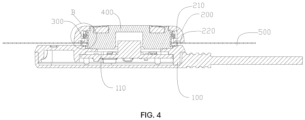
FIG. 4 is a cross-sectional view of a second embodiment of a fixing member of the locking structure configured to combine with the fabric according to an embodiment of the present disclosure. -
FIG. 5 is a partial enlarged view of portion B ofFIG. 2 . - 100, base; 110, accommodating groove; 200, upper cover; 210, ring groove; 220, recess; 300, elastic fixing ring; 310, guiding portion; 320, connecting portion; 321, snap-fit; 3211, second guiding corner; 400, fixing member; 401, pawl; 402, slot; 403, first guiding corner; 411, first annular fixing plate; 412, first fixing seat; 421, second annular fixing plate; 422, second fixing seat; 4221, mounting groove; 500, fabric.
- The technical solutions in the present disclosure will be clearly and completely described hereinafter in combination with the accompanying drawings. Obviously, the described embodiments are only a part of the embodiments of the present disclosure, but not all of the embodiments. All other embodiments obtained by a person skilled in the art based on the embodiments in the present disclosure without creative efforts are within the scope of the present disclosure. In the description of the present disclosure, it should be understood that terms "center", "longitudinal", "transverse", "length", "width", "thickness", "upper", "lower", "front", "rear", "left", "right", "vertical", "horizontal", "top", "bottom", "inside", "outside", "clockwise", "counterclockwise", "axial", "radial" , "circumferential", etc. indicate an orientation or a positional relationship based on an orientation or a positional relationship shown in the drawings, which is only for the purpose of facilitating and simplifying the description of the present disclosure, rather than indicates or implies that the device or elements must have a specific orientation, be constructed and operated in a specific orientation, and therefore cannot be construed as limitation of the present disclosure.
- In addition, the terms "first" and "second" are used for descriptive purposes only, which cannot be construed as indicating or implying a relative importance, or implicitly specifying the number of the indicated technical features. Therefore, the defined "first" and "second" features may explicitly or implicitly include one or more of the features. In the description of the present disclosure, "plurality" means at least two, such as two or more than two, unless otherwise specifically defined. In the present disclosure, unless otherwise explicitly specified and defined, the terms "mounted", "coupled", "connected" and "fixed" should be understood broadly, for example, it could be understood as a fixed connection, or a detachable connection, or integrated; it could be understood as a mechanical connection, or an electrical connection; it could be understood as a direct connection, an indirect connection through an intermediate medium; and it could be understood as an internal connection between two elements, or an interaction between two elements. For a person skilled in the art, the specific meaning of the aforementioned terms in the present disclosure can be understood according to specific situations.
- The present disclosure will be further described in detail hereinafter by specific embodiments and in combination with the accompanying drawings.
- Referring to
FIGS. 1 ,2 ,3 ,4 , and5 , a locking structure configured to combine with a fabric is provided according to an embodiment of the present disclosure, which includes abase 100, anupper cover 200, and anelastic fixing ring 300. Thebase 100 is provided with anaccommodating groove 110 configured to hold a control switch. A top surface of thebase 100 is provided with a fixingmember 400 fixed at theaccommodating groove 110, and the fixingmember 400 is provided with apawl 401 configured to grasp thefabric 500. An inner wall of theupper cover 200 is provided with aring groove 210 configured to accommodate theelastic fixing ring 300. An inner wall of theelastic fixing ring 300 is provided with a snap-fit 321. An outer wall of the fixingmember 400 is provided with aslot 402 configured to be engaged with the snap-fit 321. When the snap-fit 321 is engaged with theslot 402, a bottom of theupper cover 200 is capable of abutting against thepawl 401. - In a specific use, the fixing
member 400 is provided on thebase 100, and thefabric 500 is provided with a circular hole. Thefabric 500 is then sleeved over thebase 100, and the fixingmember 400 protrudes from thefabric 500. Then, a user or a worker may mount theelastic fixing ring 300 in thering groove 210 on the inner wall of theupper cover 200, and theupper cover 200 and theelastic fixing ring 300 are then mounted on the fixingmember 400 together, with theelastic fixing ring 300 sleeving outside the fixingmember 400. During this process, the snap-fit 321 provided on the inner wall of theelastic fixing ring 300 can be engaged in theslot 402 on the outer wall of the fixingmember 400, thereby achieving a connection between theupper cover 200 and the fixingmember 400, and theupper cover 200 can press thefabric 500 against thebase 100, at which time thepawl 401 provided at a bottom of the fixingmember 400 can be inserted into thefabric 500, and thepawl 401 can abut against the bottom of theupper cover 200, thus thefabric 500 is fixed. Through this arrangement, components such as a control switch can be fixed on thefabric 500, and it is not easy for the control switch wire to be torn. - Referring to
FIGS. 1 ,2 ,3 ,4 , and5 , in an optional embodiment, an outer edge of a top of the fixingmember 400 is provided with afirst guiding corner 403 configured to expand theelastic fixing ring 300, and an inner edge of a bottom of the snap-fit 321 is provided with asecond guiding corner 3211 adapted to thefirst guiding corner 403. - In an embodiment of the present disclosure, the outer edge of the top of the fixing
member 400 is provided with thefirst guiding corner 403, and the inner edge of the bottom of the snap-fit 321 is provided with thesecond guiding corner 3211. When theelastic fixing ring 300 is mounted on thebase 100 along with theupper cover 200, thesecond guiding corner 3211 at the bottom of the snap-fit 321 can be in contact with thefirst guiding corner 403 at the top of the fixingmember 400, and theelastic fixing ring 300 can be expanded along thefirst guiding corner 403, such that the snap-fit 321 on theelastic fixing ring 300 can be engaged in theslot 402 on the fixingmember 400. Referring toFIGS. 1 ,2 ,3 ,4 , and5 , in an optional embodiment, theelastic fixing ring 300 includes a guiding portion and a connecting portion that are integrally formed. The guidingportion 310 is shaped as a frustum of a cone. The snap-fit 321 is provided on the connectingportion 320. When the snap-fit 321 is engaged with theslot 402, an end of the snap-fit 321 away from the guidingportion 310 can abut against thering groove 210. - In an embodiment of the present disclosure, an upper portion of the
elastic fixing ring 300 is the guidingportion 310, a lower portion of theelastic fixing ring 300 is the connectingportion 320, and the guidingportion 310 is shaped as a frustum of a cone. When theelastic fixing ring 300 is provided in theupper cover 200, the guidingportion 310 shaped as a frustum of a cone can enable theelastic fixing ring 300 to be smoothly provided in thering groove 210 on the inner wall of theupper cover 200. - It should be understood that the
elastic fixing ring 300 may be a C-shaped spring coil. - Referring to
FIGS. 2 and3 , in an optional embodiment, the fixingmember 400 includes a firstannular fixing plate 411 and a first fixingseat 412. The first fixingseat 412 is provided in theaccommodating groove 110, and the first fixingseat 412 is provided with theslot 402. The firstannular fixing plate 411 is provided on the top surface of thebase 100, the first fixingseat 412 is provided in the firstannular fixing plate 411, and the firstannular fixing plate 411 is provided with thepawl 401. - The fixing
member 400 may take the form of the firstannular fixing plate 411 and the first fixingseat 412. - In an embodiment of the present disclosure, the first fixing
seat 412 is provided in theaccommodating groove 110, the firstannular fixing plate 411 is provided on thebase 100, and theslot 402 is provided on the first fixingseat 412. When mounting theupper cover 200 and theelastic fixing ring 300, the snap-fit 321 on theelastic fixing ring 300 can be engaged in theslot 402 on the first fixingseat 412, and the bottom of theupper cover 200 and thepawl 402 provided on the first annular fixing plate can fix and lock thefabric 500. - Referring to
FIGS. 2 and3 , in an optional embodiment, a cross-section of a portion of the firstannular fixing plate 411 at thepawl 401 is L-shaped. - Referring to
FIGS. 4 and5 , in an optional embodiment, the fixingmember 400 includes a secondannular fixing plate 421 and a second fixingseat 422. Thesecond fixing seat 422 is provided in theaccommodating groove 110, an outer wall of the second fixingseat 422 is provided with a mountinggroove 4221 configured to mount the secondannular fixing plate 421. The secondannular fixing plate 421 is provided with theslot 402 and thepawl 401. - The fixing
member 400 may also take the form of the secondannular fixing plate 421 and the second fixingseat 422. - In an embodiment of the present disclosure, the second
annular fixing plate 421 is provided in the mountinggroove 4221 on the outer wall of the second fixingseat 422, and the second fixing seat is then provided in thebase 100. When assembling theupper cover 200, the snap-fit 321 of theelastic fixing ring 300 in the inner wall of theupper cover 200 abuts against theslot 402 on the secondannular fixing plate 421. After the mounting of theupper cover 200 is completed, thefabric 500 is clamped between theupper cover 200 andpawl 401 on the secondannular fixing plate 421. Through this arrangement, theelastic fixing ring 300 will not damage the second fixingseat 422, and the secondannular fixing plate 421 can be replaced after long-term use to maintain a stable connection. - Referring to
FIGS. 4 and5 , in an optional embodiment, a cross-section of a portion of the secondannular fixing plate 421 at thepawl 401 is G-shaped. - Referring to
FIGS. 1 to 5 , in an optional embodiment, thebase 100 is provided with a cavity configured to provide a control component. - In an embodiment of the present disclosure, other devices such control switch can be provided in the
base 100. - Referring to
FIGS. 1 to 5 , in an optional embodiment, the bottom of theupper cover 200 is provided with arecess 220 configured to adapt to thepawl 401. - In an embodiment of the present disclosure, the bottom of the
upper cover 200 is provided with therecess 220. Therecess 220 adapts to thepawl 401, such that a contact area between both theupper cover 200 and thepawl 401 and thefabric 500 is increased, thereby increasing the stability of the fixing of thefabric 500. - Referring to
FIGS. 1 to 5 , in an optional embodiment, a cross-section of therecess 220 is shaped as a trapezoid. - In an embodiment of the present disclosure, the
recess 220 may be provided as atrapezoidal recess 220. - Finally, it should be noted that the above embodiments are only used to illustrate, but not to limit the technical solutions of the present disclosure. Although the present disclosure has been described in detail with reference to the aforementioned embodiments, a person skilled in the art should understand that modifications to technical solutions recited in the aforementioned embodiments or equivalent replacements of some or all of the technical features therein can still be made, and modifications or equivalent replacements do not make the essence of the corresponding technical solutions depart from the scope of the technical solutions of the embodiments of the present disclosure.
- A locking structure configured to combine with a fabric is provided in the present disclosure, which relates to the technical field of daily supplies. The locking structure configured to combine with the fabric includes a base, an upper cover, and an elastic fixing ring. The base is provided with an accommodating groove configured to hold a control switch, a top surface of the base is provided with a fixing member fixed at the accommodating groove, and the fixing member is provided with a pawl configured to grasp the fabric. An inner wall of the upper cover is provided with a ring groove configured to accommodate the elastic fixing ring. An inner wall of the elastic fixing ring is provided with a snap-fit. An outer wall of the fixing member is provided with a slot configured to engage the snap-fit, and when the snap-fit is engaged with the slot, a bottom of the upper cover can abut against the pawl. Thus, a technical effect that the control switch wire is not easily damaged is achieved.
- In addition, it can be understood that the locking structure configured to combine with the fabric according to the present disclosure is reproducible and can be used in various industrial applications. For example, the locking structure configured to combine with the fabric according to the present disclosure can be used in the technical field of daily supplies.
Claims (11)
- A locking structure configured to combine with a fabric, comprising a base (100), an upper cover (200), and an elastic fixing ring (300);wherein the base (100) is provided with an accommodating groove (110) configured to hold a control switch, a top surface of the base (100) is provided with a fixing member (400) fixed at the accommodating groove (110), and the fixing member (400) is provided with a pawl (401) configured to grasp the fabric (500); andwherein an inner wall of the upper cover (200) is provided with a ring groove (210) configured to accommodate the elastic fixing ring (300), an inner wall of the elastic fixing ring (300) is provided with a snap-fit (321), an outer wall of the fixing member (400) is provided with a slot (402) configured to engage the snap-fit (321), and when the snap-fit (321) is engaged with the slot (402), a bottom of the upper cover (200) is capable of abutting against the pawl (401).
- The locking structure configured to combine with the fabric according to claim 1, wherein an outer edge of a top of the fixing member (400) is provided with a first guiding corner (403) configured to expand the elastic fixing ring (300), and an inner edge of a bottom of the snap-fit (321) is provided with a second guiding corner (3211) adapted to the first guiding corner (403).
- The locking structure configured to combine with the fabric according to claim 1, wherein the elastic fixing ring (300) comprises a guiding portion (310) and a connecting portion (320) that are integrally formed, the guiding portion (310) is shaped as a frustum of a cone, the snap-fit (321) is provided on the connecting portion (320), when the snap-fit (321) is engaged with the slot (402), an end of the snap-fit (321) away from the guiding portion (310) is capable of abutting against the ring groove (210).
- The locking structure configured to combine with the fabric according to any one of claims 1 to 3, wherein the elastic fixing ring (300) is a C-shaped spring coil.
- The locking structure configured to combine with the fabric according to claim 1, wherein the fixing member (400) comprises a first annular fixing plate (411) and a first fixing seat (412),
the first fixing seat (412) is provided in the accommodating groove (110), and the first fixing seat (412) is provided with the slot (402), the first annular fixing plate (411) is provided on the top surface of the base (100), the first fixing seat (412) is provided in the first annular fixing plate (411), and the first annular fixing plate (411) is provided with the pawl (401). - The locking structure configured to combine with the fabric according to claim 5, wherein a cross-section of a portion of the first annular fixing plate (411) at the pawl (401) is L-shaped.
- The locking structure configured to combine with the fabric according to claim 1, wherein the fixing member (400) further comprises a second annular fixing plate (421) and a second fixing seat (422), the second fixing seat (422) is provided in the accommodating groove (110), an outer wall of the second fixing seat (422) is provided with a mounting groove (4221) configured to mount the second annular fixing plate (421), and the second annular fixing plate (421) is provided with the slot (402) and the pawl (401).
- The locking structure configured to combine with the fabric according to claim 7, wherein a cross-section of a portion of the second annular fixing plate (421) at the pawl (401) is G-shaped.
- The locking structure configured to combine with the fabric according to any one of claims 1 to 8, wherein the base (100) is provided with a cavity configured to provide a control component.
- The locking structure configured to combine with the fabric according to any one of claims 1 to 8, wherein the bottom of the upper cover (200) is provided with a recess (220) configured to adapt to the pawl (401).
- The locking structure configured to combine with the fabric according to claim 10, wherein a cross-section of the recess (220) is shaped as a trapezoid.
Applications Claiming Priority (2)
| Application Number | Priority Date | Filing Date | Title |
|---|---|---|---|
| CN202122405924.8U CN215723104U (en) | 2021-09-30 | 2021-09-30 | Locking structure for combining with cloth |
| PCT/CN2022/116831 WO2023051167A1 (en) | 2021-09-30 | 2022-09-02 | Locking structure used to combine with fabric |
Publications (4)
| Publication Number | Publication Date |
|---|---|
| EP4393343A1 true EP4393343A1 (en) | 2024-07-03 |
| EP4393343A4 EP4393343A4 (en) | 2025-05-21 |
| EP4393343C0 EP4393343C0 (en) | 2026-03-04 |
| EP4393343B1 EP4393343B1 (en) | 2026-03-04 |
Family
ID=80027031
Family Applications (1)
| Application Number | Title | Priority Date | Filing Date |
|---|---|---|---|
| EP22874558.4A Active EP4393343B1 (en) | 2021-09-30 | 2022-09-02 | Locking structure used to combine with fabric |
Country Status (5)
| Country | Link |
|---|---|
| US (1) | US20250031808A1 (en) |
| EP (1) | EP4393343B1 (en) |
| JP (1) | JP7874345B2 (en) |
| CN (1) | CN215723104U (en) |
| WO (1) | WO2023051167A1 (en) |
Families Citing this family (2)
| Publication number | Priority date | Publication date | Assignee | Title |
|---|---|---|---|---|
| CN215723104U (en) * | 2021-09-30 | 2022-02-01 | 苏州捷迪纳米科技有限公司 | Locking structure for combining with cloth |
| CN222443332U (en) * | 2024-05-14 | 2025-02-11 | 浙江伟星实业发展股份有限公司 | Ultrathin four-in-one buckle |
Family Cites Families (15)
| Publication number | Priority date | Publication date | Assignee | Title |
|---|---|---|---|---|
| GB100313A (en) * | 1915-04-21 | 1916-05-18 | Snyder Snap Button & Fastener | Improvements in and relating to Snap Fasteners. |
| GB112385A (en) * | 1917-06-28 | 1918-01-10 | Hubert Alexander Gill | Improvements in and relating to Stud and Socket Fasteners. |
| JPH0637704Y2 (en) * | 1988-08-02 | 1994-10-05 | 株式会社丸上 | Eyelet hook |
| US5189768A (en) * | 1991-10-29 | 1993-03-02 | Randolph-Rand Corporation | Snap fastener with separator spring |
| JP4220456B2 (en) * | 2004-11-12 | 2009-02-04 | 株式会社東京錠前製作所 | Stopper with locking mechanism |
| JP3116353U (en) | 2005-09-02 | 2005-12-02 | 有限会社井上精工 | Germanium fitting |
| JP5321374B2 (en) * | 2009-09-10 | 2013-10-23 | 株式会社富士通ゼネラル | Electric carpet |
| JP2014094230A (en) * | 2012-11-12 | 2014-05-22 | Morito Co Ltd | Light emission snap button |
| JP2014145404A (en) | 2013-01-28 | 2014-08-14 | Tokai Tac:Kk | Hook device |
| JP2016049344A (en) * | 2014-09-01 | 2016-04-11 | 株式会社カジテック | Snap fastener |
| CN204465646U (en) * | 2015-03-25 | 2015-07-08 | 广东欧珀移动通信有限公司 | mobile terminal |
| KR101949872B1 (en) * | 2018-08-07 | 2019-02-19 | 에이씨와이테크놀로지 주식회사 | wearable temperature controller mounting structure and its Mounting method |
| CN210197017U (en) * | 2019-05-19 | 2020-03-27 | 南安易盾格商贸有限公司 | Buckle type LED lamp |
| CN213281782U (en) * | 2020-08-24 | 2021-05-28 | 惠州市合生金属制品有限公司 | Novel combined snap fastener with double buckles |
| CN215723104U (en) * | 2021-09-30 | 2022-02-01 | 苏州捷迪纳米科技有限公司 | Locking structure for combining with cloth |
-
2021
- 2021-09-30 CN CN202122405924.8U patent/CN215723104U/en active Active
-
2022
- 2022-09-02 US US18/696,911 patent/US20250031808A1/en not_active Abandoned
- 2022-09-02 EP EP22874558.4A patent/EP4393343B1/en active Active
- 2022-09-02 WO PCT/CN2022/116831 patent/WO2023051167A1/en not_active Ceased
- 2022-09-02 JP JP2024519763A patent/JP7874345B2/en active Active
Also Published As
| Publication number | Publication date |
|---|---|
| CN215723104U (en) | 2022-02-01 |
| EP4393343A4 (en) | 2025-05-21 |
| JP7874345B2 (en) | 2026-06-16 |
| US20250031808A1 (en) | 2025-01-30 |
| WO2023051167A1 (en) | 2023-04-06 |
| EP4393343C0 (en) | 2026-03-04 |
| JP2024536650A (en) | 2024-10-07 |
| EP4393343B1 (en) | 2026-03-04 |
Similar Documents
| Publication | Publication Date | Title |
|---|---|---|
| EP4393343B1 (en) | Locking structure used to combine with fabric | |
| KR100315673B1 (en) | Locking device for battery pack in portable radiotelephone | |
| US20040204176A1 (en) | Battery and battery locking unit of mobile terminal | |
| US6705574B2 (en) | Cable mounting structure | |
| CN205376902U (en) | Industrial connector | |
| CN221041705U (en) | Anti-pulling radio frequency communication wire harness | |
| EP3214703A1 (en) | Power line assembly and electronic device | |
| JP2020087919A (en) | Battery product | |
| CN213692515U (en) | Plug-in component and socket | |
| CN211822699U (en) | Electric heater | |
| US7046206B2 (en) | Structure for mounting antenna | |
| CN217825687U (en) | Novel lower casing | |
| CN221525335U (en) | Plastic reed nut seat | |
| CN215036735U (en) | Tray and robot | |
| CN211106418U (en) | Printer and printing method | |
| CN215777232U (en) | Cooking utensil | |
| CN112582840A (en) | Plug-in component and socket | |
| CN217751250U (en) | Self-centering wedge type clutch assembly tool | |
| CN220151100U (en) | Novel key sleeve structure for automobile key | |
| CN218105516U (en) | Tableware box connecting piece and tableware box | |
| CN217427962U (en) | Detachable parameter adjusting module of frequency converter | |
| CN221105686U (en) | Safety armrest | |
| CN213524790U (en) | Detachable Christmas tree collar | |
| US20250102003A1 (en) | Fastener | |
| CN213810477U (en) | Magnet mounting structure |
Legal Events
| Date | Code | Title | Description |
|---|---|---|---|
| STAA | Information on the status of an ep patent application or granted ep patent |
Free format text: STATUS: THE INTERNATIONAL PUBLICATION HAS BEEN MADE |
|
| PUAI | Public reference made under article 153(3) epc to a published international application that has entered the european phase |
Free format text: ORIGINAL CODE: 0009012 |
|
| STAA | Information on the status of an ep patent application or granted ep patent |
Free format text: STATUS: REQUEST FOR EXAMINATION WAS MADE |
|
| 17P | Request for examination filed |
Effective date: 20240328 |
|
| AK | Designated contracting states |
Kind code of ref document: A1 Designated state(s): AL AT BE BG CH CY CZ DE DK EE ES FI FR GB GR HR HU IE IS IT LI LT LU LV MC MK MT NL NO PL PT RO RS SE SI SK SM TR |
|
| DAV | Request for validation of the european patent (deleted) | ||
| DAX | Request for extension of the european patent (deleted) | ||
| A4 | Supplementary search report drawn up and despatched |
Effective date: 20250422 |
|
| RIC1 | Information provided on ipc code assigned before grant |
Ipc: F16B 5/06 20060101ALI20250414BHEP Ipc: F16B 21/07 20060101ALI20250414BHEP Ipc: H05B 1/00 20060101ALI20250414BHEP Ipc: F21V 23/04 20060101ALI20250414BHEP Ipc: A44B 17/00 20060101AFI20250414BHEP |
|
| GRAP | Despatch of communication of intention to grant a patent |
Free format text: ORIGINAL CODE: EPIDOSNIGR1 |
|
| STAA | Information on the status of an ep patent application or granted ep patent |
Free format text: STATUS: GRANT OF PATENT IS INTENDED |
|
| INTG | Intention to grant announced |
Effective date: 20250929 |
|
| RIC1 | Information provided on ipc code assigned before grant |
Ipc: A44B 17/00 20060101AFI20250922BHEP Ipc: F21V 23/04 20060101ALI20250922BHEP Ipc: H05B 1/00 20060101ALI20250922BHEP Ipc: F16B 21/07 20060101ALI20250922BHEP Ipc: F16B 5/06 20060101ALI20250922BHEP |
|
| GRAS | Grant fee paid |
Free format text: ORIGINAL CODE: EPIDOSNIGR3 |
|
| GRAA | (expected) grant |
Free format text: ORIGINAL CODE: 0009210 |
|
| STAA | Information on the status of an ep patent application or granted ep patent |
Free format text: STATUS: THE PATENT HAS BEEN GRANTED |
|
| AK | Designated contracting states |
Kind code of ref document: B1 Designated state(s): AL AT BE BG CH CY CZ DE DK EE ES FI FR GB GR HR HU IE IS IT LI LT LU LV MC MK MT NL NO PL PT RO RS SE SI SK SM TR |
|
| REG | Reference to a national code |
Ref country code: CH Ref legal event code: F10 Free format text: ST27 STATUS EVENT CODE: U-0-0-F10-F00 (AS PROVIDED BY THE NATIONAL OFFICE) Effective date: 20260304 Ref country code: GB Ref legal event code: FG4D |
|
| REG | Reference to a national code |
Ref country code: DE Ref legal event code: R096 Ref document number: 602022031859 Country of ref document: DE |
|
| REG | Reference to a national code |
Ref country code: IE Ref legal event code: FG4D |
|
| U01 | Request for unitary effect filed |
Effective date: 20260401 |
|
| U07 | Unitary effect registered |
Designated state(s): AT BE BG DE DK EE FI FR IT LT LU LV MT NL PT RO SE SI Effective date: 20260410 |
|
| PG25 | Lapsed in a contracting state [announced via postgrant information from national office to epo] |
Ref country code: RS Free format text: LAPSE BECAUSE OF FAILURE TO SUBMIT A TRANSLATION OF THE DESCRIPTION OR TO PAY THE FEE WITHIN THE PRESCRIBED TIME-LIMIT Effective date: 20260604 |
|
| PG25 | Lapsed in a contracting state [announced via postgrant information from national office to epo] |
Ref country code: ES Free format text: LAPSE BECAUSE OF FAILURE TO SUBMIT A TRANSLATION OF THE DESCRIPTION OR TO PAY THE FEE WITHIN THE PRESCRIBED TIME-LIMIT Effective date: 20260304 |
|
| U1N | Appointed representative for the unitary patent procedure changed after the registration of the unitary effect |
Representative=s name: ING. C. CORRADINI & C. S.R.L.; IT |
|
| PG25 | Lapsed in a contracting state [announced via postgrant information from national office to epo] |
Ref country code: PL Free format text: LAPSE BECAUSE OF FAILURE TO SUBMIT A TRANSLATION OF THE DESCRIPTION OR TO PAY THE FEE WITHIN THE PRESCRIBED TIME-LIMIT Effective date: 20260304 |
|
| PG25 | Lapsed in a contracting state [announced via postgrant information from national office to epo] |
Ref country code: GR Free format text: LAPSE BECAUSE OF FAILURE TO SUBMIT A TRANSLATION OF THE DESCRIPTION OR TO PAY THE FEE WITHIN THE PRESCRIBED TIME-LIMIT Effective date: 20260605 |
|
| PG25 | Lapsed in a contracting state [announced via postgrant information from national office to epo] |
Ref country code: NO Free format text: LAPSE BECAUSE OF FAILURE TO SUBMIT A TRANSLATION OF THE DESCRIPTION OR TO PAY THE FEE WITHIN THE PRESCRIBED TIME-LIMIT Effective date: 20260604 |
|
| PG25 | Lapsed in a contracting state [announced via postgrant information from national office to epo] |
Ref country code: HR Free format text: LAPSE BECAUSE OF FAILURE TO SUBMIT A TRANSLATION OF THE DESCRIPTION OR TO PAY THE FEE WITHIN THE PRESCRIBED TIME-LIMIT Effective date: 20260304 |