EP4393324A1 - Machine for manufacturing rods - Google Patents
Machine for manufacturing rods Download PDFInfo
- Publication number
- EP4393324A1 EP4393324A1 EP23214246.3A EP23214246A EP4393324A1 EP 4393324 A1 EP4393324 A1 EP 4393324A1 EP 23214246 A EP23214246 A EP 23214246A EP 4393324 A1 EP4393324 A1 EP 4393324A1
- Authority
- EP
- European Patent Office
- Prior art keywords
- sharpening
- cutting blade
- rods
- cutting
- machine according
- Prior art date
- Legal status (The legal status is an assumption and is not a legal conclusion. Google has not performed a legal analysis and makes no representation as to the accuracy of the status listed.)
- Granted
Links
Images


Classifications
-
- A—HUMAN NECESSITIES
- A24—TOBACCO; CIGARS; CIGARETTES; SIMULATED SMOKING DEVICES; SMOKERS' REQUISITES
- A24D—CIGARS; CIGARETTES; TOBACCO SMOKE FILTERS; MOUTHPIECES OF CIGARS OR CIGARETTES; MANUFACTURE OF TOBACCO SMOKE FILTERS OR MOUTHPIECES
- A24D3/00—Tobacco smoke filters, e.g. filter tips or filtering inserts; Filters specially adapted for simulated smoking devices; Mouthpieces of cigars or cigarettes
- A24D3/02—Manufacture of tobacco smoke filters
- A24D3/025—Final operations, i.e. after the filter rod forming process
- A24D3/0254—Cutting means
-
- A—HUMAN NECESSITIES
- A24—TOBACCO; CIGARS; CIGARETTES; SIMULATED SMOKING DEVICES; SMOKERS' REQUISITES
- A24C—MACHINES FOR MAKING CIGARS OR CIGARETTES
- A24C5/00—Making cigarettes; Making tipping materials for, or attaching filters or mouthpieces to, cigars or cigarettes
- A24C5/14—Machines of the continuous-rod type
- A24C5/28—Cutting-off the tobacco rod
- A24C5/30—Machines combined with devices for grinding the knives
Definitions
- the present invention relates to a machine for manufacturing rods, for example rods for the production of smoking articles.
- This sharpening operation performed on the machine presents the drawback of subjecting the rods and the manufacturing machine itself to the sparks generated by the sharpening operation. This drawback can be mitigated through the use of particular steels that are less liable to generate sparks for the production of the cutting blades.
- blades made of hard metal are able to keep a suitable cutting edge for millions of cycles.
- At the end of a cycle of service life of the cutting blade it is known to provide for replacement of the worn cutting blade with a new blade, or else carry out a sharpening operation at purposely provided machining stations separate from, and completely independent of, the machine after prior dismantling of the cutting blade from the machine.
- the present invention proposes a solution that is improved over the prior art, in particular that will enable control and management of the cutting blades used on the machine that is simpler, more efficient, and more reliable.
- the present invention regards a machine for manufacturing rods, in particular rods for the production of smoking articles.
- the machine described herein may be used for the production of sticks or lengths consisting of tobacco, filter material, paper, etc.
- the cutting blade 122 is positioned at a point of the feed path K in such a way that the cutting edge 122A will pass, in a transverse direction, right through each rod moved along the feed path K as a result precisely of the movement of advance of the rod along the path K itself.
- the cutting blade 122 is made of hard metal (cemented carbide), i.e., a sintered composite metal containing a metal carbide and a binder metal.
- the hard metal may have one of the following formulations: WC-Co, (W-Ti)C-Co, (W-Ti-Ta-Nb)C-Co.
- the percentage of cobalt may range between 3% and 25%.
- the cutting station 120 comprises a sharpening unit 140 for sharpening the cutting blade 122 in its position P along the feed path K.
- the sharpening unit 140 preferably comprises two sharpening disks 141, 142, positioned on opposite sides of the rotary cutting blade 122, that rotate about respective axes of rotation I1, I2 set alongside one another and inclined, with respect to the axis of rotation I of the cutting blade 122, according to opposite angles.
- the two sharpening disks 141, 142 are configured to operate, respectively, on the opposite sides of the cutting edge 122A, via removal of material, so as to generate two new sides parallel to the previous ones and consequently a new cutting edge 122A.
- the two sharpening disks 141, 142 are formed by grinding wheels, preferably resin-bonded diamond wheels.
- the basic structure of the grinding wheels may be made of aluminium, steel, an aluminium and resin composite, etc.
- the grain size of the diamond wheels is comprised in the range D91-D151 (according to the classification FEPA - Fédération Eurotigenne des Fabricants de Produits Abrasifs).
- the two sharpening disks 141, 142 and the corresponding actuators 151, 152 are mounted on a mobile support 156, which is moved vertically by the actuator 154 between a lowered position corresponding to the aforesaid resting position of the sharpening disks 141, 142 and a raised position corresponding to the aforesaid working position.
- the actuator 154 comprises an axially mobile vertical stem 157 and a rotary electric motor 158 operatively connected to the stem 157.
- the signal of start of a sharpening operation may be generated upon reaching of a total number of work cycles carried out by the machine 100 (or by the cutting blade 122) equal to a given threshold number.
- the start signal may be generated at the moment when the data coming from the aforesaid sensors indicate a non-suitable state of the cutting blade 122.
- the operation of sharpening of the cutting blade 122 may be carried out either in concomitance with a working cycle of the machine and when the machine is not operating, for example during interruption of a working cycle or else at the end of a working cycle and before start of a new cycle.
- the two sharpening disks 141, 142 turning about the respective axes of rotation I1, I2 are simultaneously moved in the direction of the cutting blade 122 according to a predefined pitch, to remove a given amount of material from the blade itself.
- the aforesaid movement can be driven by the same actuator 154 as the one described above.
Landscapes
- Debarking, Splitting, And Disintegration Of Timber (AREA)
- Harvester Elements (AREA)
- Sawing (AREA)
Abstract
- a succession of rotary drums (101), each having on a respective lateral surface a plurality of seats for housing the rods and being configured to move the rods, as a result of their rotation, along a feed path (K), according to an orientation such that the rods are oriented with their own longitudinal axis set in a direction transverse to the feed path (K); and
- a cutting station (120) positioned along the feed path (K), comprising a rotary cutting blade (122), configured to cut the rods that advance along the feed path (K) so as to divide each of them into at least two parts, wherein said cutting blade (122) is made of hard metal.
Description
- The present invention relates to a machine for manufacturing rods, for example rods for the production of smoking articles.
- In particular, the present invention regards a machine of the type comprising:
- a succession of rotary drums, each having on a respective lateral surface a plurality of seats for housing the rods and being configured to move the rods, as a result of their rotation, along a feed path, according to an orientation such that the rods are oriented with their own longitudinal axis set in a direction transverse to the feed path; and
- a cutting station positioned along the feed path, comprising a rotary cutting blade, configured to cut the rods that advance along the feed path so as to divide each of these into at least two parts.
- For a machine of the type referred to above there is felt the need to guarantee that the cutting blade used is in a condition to ensure precise and faultless cutting of the rods.
- In this connection, for cutting blades made of steel it is known to carry out an operation of sharpening of the steel blades continuously during operation of the machine.
- This sharpening operation performed on the machine presents the drawback of subjecting the rods and the manufacturing machine itself to the sparks generated by the sharpening operation. This drawback can be mitigated through the use of particular steels that are less liable to generate sparks for the production of the cutting blades.
- The introduction of cutting blades made of hard metal has made it possible to eliminate the need for carrying out continuous sharpening during operation of the machine.
- In fact, blades made of hard metal are able to keep a suitable cutting edge for millions of cycles. At the end of a cycle of service life of the cutting blade it is known to provide for replacement of the worn cutting blade with a new blade, or else carry out a sharpening operation at purposely provided machining stations separate from, and completely independent of, the machine after prior dismantling of the cutting blade from the machine.
- In this context, the present invention proposes a solution that is improved over the prior art, in particular that will enable control and management of the cutting blades used on the machine that is simpler, more efficient, and more reliable.
- In general, the present invention regards a manufacturing machine according to claim 1, and a method for manufacturing rods according to
claim 12. - The claims form an integral part of the teaching provided herein.
- Further characteristics and advantages of the present invention will emerge clearly from the ensuing description, with reference to the annexed drawings, which are provided purely by way of non-limiting example and in which:
-
Figure 1 is a schematic illustration of an example of the manufacturing machine described herein; -
Figure 2 illustrates an example of a cutting station for the machine described herein; and -
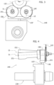
Figures 3 and 4 are, respectively, a front view and a side view of a sharpening unit of the cutting station ofFigure 2 . - In the ensuing description various specific details are illustrated aimed at enabling an in-depth understanding of the embodiments. The embodiments may be provided without one or more of the specific details, or with other methods, components, or materials, etc. In other cases, known structures, materials, or operations are not illustrated or described in detail so that various aspects of the embodiment will not be obscured.
- The references used herein are provided merely for convenience and hence do not define the sphere of protection or the scope of the embodiments.
- As mentioned at the start, the present invention regards a machine for manufacturing rods, in particular rods for the production of smoking articles. For instance, the machine described herein may be used for the production of sticks or lengths consisting of tobacco, filter material, paper, etc.
- With reference to
Figure 1 , the machine described herein - designated in the figures as a whole by the reference number 100 - comprises a succession ofrotary drums 101 for moving the rods, as a result of their rotation, along a feed path K, from aninlet 102 to anoutlet 106. - In the aforesaid movement, the rods are oriented with their own longitudinal axis set in a direction transverse to the feed path K.
- In particular, the
drums 101 each have, on the respective outer lateral surface, a plurality of seats (not illustrated) for housing the rods, which extend along the periphery of the drum, about the axis of rotation thereof, and in which the rods are received, setting themselves parallel to the axis of rotation of each single drum. - The
manufacturing machine 100 further comprises acutting station 120, positioned along the feed path K and having the function of cutting the rods that advance along the path itself so as to divide each of them into at least two parts. - With reference to
Figure 2 , thecutting station 120 comprises arotary cutting blade 122, rotatable an axis of rotation I parallel to the axes of rotation of thedrums 101. Arotary motor 124 is configured to drive thecutting blade 122 in rotation. - In one or more preferred embodiments like the one illustrated, the
cutting blade 122 is in the form of a sharpened disk comprising a peripheralcircular cutting edge 122A. - In a way in itself known, the
cutting blade 122 is positioned at a point of the feed path K in such a way that thecutting edge 122A will pass, in a transverse direction, right through each rod moved along the feed path K as a result precisely of the movement of advance of the rod along the path K itself. - According to an important characteristic of the solution described herein, the
cutting blade 122 is made of hard metal (cemented carbide), i.e., a sintered composite metal containing a metal carbide and a binder metal. - The hard metal may have one of the following formulations: WC-Co, (W-Ti)C-Co, (W-Ti-Ta-Nb)C-Co. The percentage of cobalt may range between 3% and 25%.
- According to a further important characteristic of the solution described herein, the
cutting station 120 comprises asharpening unit 140 for sharpening thecutting blade 122 in its position P along the feed path K. - The
sharpening unit 140 preferably comprises twosharpening disks rotary cutting blade 122, that rotate about respective axes of rotation I1, I2 set alongside one another and inclined, with respect to the axis of rotation I of thecutting blade 122, according to opposite angles. - In a way in itself known, the two
sharpening disks cutting edge 122A, via removal of material, so as to generate two new sides parallel to the previous ones and consequently anew cutting edge 122A. - In one or more preferred embodiments like the one illustrated, the two
sharpening disks - In one or more preferred embodiments like the one illustrated, the two
sharpening disks rotary motors disks - In one or more preferred embodiments like the one illustrated, the
cutting station 120 comprises anactuator 154 for moving the twosharpening disks disks cutting blade 122, and a working position, in which the twodisks cutting blade 122 and can carry out sharpening thereof. - In one or more preferred embodiments like the one illustrated, the two
sharpening disks corresponding actuators mobile support 156, which is moved vertically by theactuator 154 between a lowered position corresponding to the aforesaid resting position of thesharpening disks actuator 154 comprises an axially mobilevertical stem 157 and a rotary electric motor 158 operatively connected to thestem 157. - In one or more preferred embodiments like the one illustrated, the machine 10 comprises a
control unit 160 configured for driving theactuator 154 in order to bring thesharpening disks - The aforesaid start signal may be generated by the control unit, or else by a further control unit, on the basis of data coming from a counter of the work cycles of the
cutting blade 122 or else on the basis of data obtained from the detections made by one or more sensors on thecutting blade 122. - In the former case, the signal of start of a sharpening operation may be generated upon reaching of a total number of work cycles carried out by the machine 100 (or by the cutting blade 122) equal to a given threshold number. In the latter case, instead, the start signal may be generated at the moment when the data coming from the aforesaid sensors indicate a non-suitable state of the
cutting blade 122. - The operation of sharpening of the
cutting blade 122 may be carried out either in concomitance with a working cycle of the machine and when the machine is not operating, for example during interruption of a working cycle or else at the end of a working cycle and before start of a new cycle. - In a way in itself known, during the sharpening operation, the two
sharpening disks cutting blade 122 according to a predefined pitch, to remove a given amount of material from the blade itself. The aforesaid movement can be driven by thesame actuator 154 as the one described above. - The present applicant has been able to note that for a cutting blade made of hard metal as described above, excellent results from the standpoint of sharpening quality are obtained with a movement of advance of the two
disks - In view of the foregoing, it now appears evident that the solution described herein is able to overcome completely the drawbacks of the prior art discussed at the start. In particular, the cutting blade made of hard metal makes it possible to avoid, during the sharpening operations, subjecting the rods being manufactured and the machine itself to the sparks that are, instead, generated in known solutions that use steel cutting blades. Moreover, provision of the sharpening
unit 140 directly on board the machine, according to the solution described herein, enables an immediate start of a sharpening operation whenever required, without any need to take down the cutting blade from the machine. In this way, operation of the machine can benefit from a considerable saving of time as compared to the solutions of the prior art. - Of course, without prejudice to the principle of the invention, the details of construction and the embodiments may vary, even significantly, with respect to what has been illustrated herein purely by way of non-limiting example, without thereby departing from the scope of the invention, as defined by the annexed claims.
Claims (14)
- A machine (100) for manufacturing rods, in particular rods for the production of smoking articles, comprising:- a succession of rotary drums (101), each having on a respective lateral surface a plurality of seats for housing the rods and being configured to move the rods, as a result of their rotation, along a feed path (K), according to an orientation such that the rods are oriented with their own longitudinal axis set in a direction transverse to the feed path (K); and- a cutting station (120) positioned along the feed path (K), comprising a rotary cutting blade (122), configured to cut the rods that advance along the feed path (K) so as to divide each of them into at least two parts, wherein said cutting blade (122) is made of hard metal,said cutting station (120) further comprising a sharpening unit (140), which includes at least one sharpening member (141, 142) configured to sharpen said cutting blade (122).
- The machine according to claim 1, wherein said cutting station (120) comprises at least one actuator (154) for moving said at least one sharpening member (141, 142) between a resting position and a working position in which said at least one member can carry out sharpening of said cutting blade, said machine (100) comprising a control unit (160) configured to drive said actuator (154) so as to bring said sharpening member (141, 142) from said resting position to said working position on the basis of a signal of start of a sharpening operation.
- The machine according to claim 1 or claim 2, wherein said sharpening unit (140) comprises a first sharpening disk (141) and a second sharpening disk (141), which are set on opposite sides of said cutting blade (122) and are both mobile between a position away from said cutting blade (122), corresponding to said resting position, and a position in which said first and second disks (141, 142) are in contact with said cutting blade (122), corresponding to said working position.
- The machine according to claim 3, wherein said first and second sharpening disks (141, 142) are rotatable about respective axes of rotation (I1, I2), which are inclined with respect to the axis of rotation (I) of said cutting blade (122) according to opposite angles.
- The machine according to claim 4, comprising at least one rotary motor (151, 152) configured to drive said first and second sharpening disks (141, 142) in rotation.
- The machine according to any one of the preceding claims, wherein said cutting blade (122) is a cutting disk comprising a peripheral circular cutting edge (122A).
- The machine according to any one of the preceding claims, wherein said hard metal may have at least one of the following formulations: WC-Co, (W-Ti)C-Co, (W-Ti-Ta-Nb)C-Co.
- The machine according to any one of the preceding claims, wherein said sharpening member (141, 142) is formed by a resin-bonded diamond grinding wheel.
- The machine according to claim 2, wherein said control unit (160) is moreover configured to drive said actuator (154) so that it will move said sharpening member (141, 142) that is located in said working position in the direction of said cutting blade (122), according to a predefined pitch, to remove a given amount of material from said cutting blade.
- The machine according to claim 8, wherein said predefined pitch is comprised in the range between 0.01 and 0.03 mm.
- The machine according to any one of the preceding claims, comprising a rotary motor configured to drive said cutting blade in rotation.
- A method for manufacturing rods, in particular rods for the production of smoking articles, via a machine according to any one of the preceding claims, comprising the steps of:- in a working cycle of the machine, feeding the rods on the succession of rotary drums (101) along the feed path (K), and, at the cutting station (120), cutting the rods via the cutting blade (122) so as to divide each rod into at least two parts, said sharpening member (141, 142) being kept in said resting position; and- during the same working cycle, or during an interruption of the working cycle, or else once the working cycle is through and before start of a new working cycle, bringing said sharpening member (141, 142) into said working position and sharpening said cutting blade (122) by way of said sharpening member (141, 142).
- The method according to claim 12, wherein said sharpening step includes moving said sharpening member (141, 142) that is located in said working position in the direction of said cutting blade (122), according to a predefined pitch, to remove a given amount of material from said cutting blade (120).
- The method according to claim 13, wherein said predefined pitch is comprised in the range between 0.01 and 0.03 mm.
Applications Claiming Priority (1)
| Application Number | Priority Date | Filing Date | Title |
|---|---|---|---|
| IT102022000026361A IT202200026361A1 (en) | 2022-12-21 | 2022-12-21 | MACHINE FOR PROCESSING BARS |
Publications (2)
| Publication Number | Publication Date |
|---|---|
| EP4393324A1 true EP4393324A1 (en) | 2024-07-03 |
| EP4393324B1 EP4393324B1 (en) | 2026-05-20 |
Family
ID=85792476
Family Applications (1)
| Application Number | Title | Priority Date | Filing Date |
|---|---|---|---|
| EP23214246.3A Active EP4393324B1 (en) | 2022-12-21 | 2023-12-05 | MACHINE FOR THE PRODUCTION OF RANKING PIECES |
Country Status (2)
| Country | Link |
|---|---|
| EP (1) | EP4393324B1 (en) |
| IT (1) | IT202200026361A1 (en) |
Citations (2)
| Publication number | Priority date | Publication date | Assignee | Title |
|---|---|---|---|---|
| EP3430915A1 (en) * | 2017-07-18 | 2019-01-23 | Hauni Maschinenbau GmbH | Device for cutting rod-like articles and machine using such a device |
| EP3838003A1 (en) * | 2019-12-17 | 2021-06-23 | G.D S.p.A. | Cutting device of the tobacco industry |
-
2022
- 2022-12-21 IT IT102022000026361A patent/IT202200026361A1/en unknown
-
2023
- 2023-12-05 EP EP23214246.3A patent/EP4393324B1/en active Active
Patent Citations (2)
| Publication number | Priority date | Publication date | Assignee | Title |
|---|---|---|---|---|
| EP3430915A1 (en) * | 2017-07-18 | 2019-01-23 | Hauni Maschinenbau GmbH | Device for cutting rod-like articles and machine using such a device |
| EP3838003A1 (en) * | 2019-12-17 | 2021-06-23 | G.D S.p.A. | Cutting device of the tobacco industry |
Also Published As
| Publication number | Publication date |
|---|---|
| EP4393324B1 (en) | 2026-05-20 |
| IT202200026361A1 (en) | 2024-06-21 |
Similar Documents
| Publication | Publication Date | Title |
|---|---|---|
| EP2209556B1 (en) | Wood chipping machine with peripheral sieving and disintegration device and method for producing wood chips | |
| JP5846082B2 (en) | Grinding method for skiving cutter | |
| CN102573528B (en) | Cutting and Grinding Devices | |
| JP5089242B2 (en) | Fixed blade of shear crusher | |
| US4052822A (en) | Method and apparatus for abrasively cutting objects | |
| CN204603557U (en) | For the electrode tip reconditioning equipment device of reconditioning welding electrode head | |
| EP2524608A2 (en) | Cutting device for a rod-making machine for the tobacco processing industry and method for adjusting the position of the or each grinding wheel of a device for grinding in a cutting device for a rod-making machine for the tobacco processing industry | |
| CN102196735B (en) | cutting device | |
| CN110125473B (en) | High-precision lathe for optical axis machining | |
| CN109259301B (en) | Device for cutting rod-shaped articles and machine having such a device | |
| JP5502385B2 (en) | Double-head surface grinding method and apparatus | |
| US2830634A (en) | Adjusting device for sharpener for tobacco cutter | |
| EP2965638A1 (en) | Knife positioning apparatus | |
| KR19980032427A (en) | Grinder blade grinding method and apparatus | |
| US6036588A (en) | Knife ring [chip] cutter | |
| CN110711829B (en) | Steel wire shot cutting machine | |
| CN108161148A (en) | The electric discharge finishing apparatus in place and method of a kind of milling head | |
| US3691898A (en) | Edge burr removal apparatus | |
| EP3838003B1 (en) | Cutting device of the tobacco industry | |
| CN206952678U (en) | A kind of saw chain blade knife sharpener | |
| US4034629A (en) | Method and apparatus for automatic edge grinding of the teeth of a circular saw to an improved contour | |
| CN207997044U (en) | A kind of electric discharge finishing apparatus in place of milling head | |
| US2535672A (en) | Rotary tobacco cutting machine | |
| US3472107A (en) | Tow cutting apparatus having knife resharpening means | |
| CN102106605A (en) | Cutting device and cutting blade for cutting rod-shaped product of tobacco processing industry |
Legal Events
| Date | Code | Title | Description |
|---|---|---|---|
| PUAI | Public reference made under article 153(3) epc to a published international application that has entered the european phase |
Free format text: ORIGINAL CODE: 0009012 |
|
| STAA | Information on the status of an ep patent application or granted ep patent |
Free format text: STATUS: THE APPLICATION HAS BEEN PUBLISHED |
|
| AK | Designated contracting states |
Kind code of ref document: A1 Designated state(s): AL AT BE BG CH CY CZ DE DK EE ES FI FR GB GR HR HU IE IS IT LI LT LU LV MC ME MK MT NL NO PL PT RO RS SE SI SK SM TR |
|
| P01 | Opt-out of the competence of the unified patent court (upc) registered |
Free format text: CASE NUMBER: APP_40751/2024 Effective date: 20240710 |
|
| STAA | Information on the status of an ep patent application or granted ep patent |
Free format text: STATUS: REQUEST FOR EXAMINATION WAS MADE |
|
| 17P | Request for examination filed |
Effective date: 20241218 |
|
| GRAP | Despatch of communication of intention to grant a patent |
Free format text: ORIGINAL CODE: EPIDOSNIGR1 |
|
| STAA | Information on the status of an ep patent application or granted ep patent |
Free format text: STATUS: GRANT OF PATENT IS INTENDED |
|
| RIC1 | Information provided on ipc code assigned before grant |
Ipc: A24D 3/02 20060101AFI20251210BHEP Ipc: A24C 5/30 20060101ALN20251210BHEP |
|
| INTG | Intention to grant announced |
Effective date: 20251222 |
|
| RIC1 | Information provided on ipc code assigned before grant |
Ipc: A24D 3/02 20060101AFI20251215BHEP Ipc: A24C 5/30 20060101ALN20251215BHEP |
|
| GRAS | Grant fee paid |
Free format text: ORIGINAL CODE: EPIDOSNIGR3 |
|
| GRAA | (expected) grant |
Free format text: ORIGINAL CODE: 0009210 |
|
| STAA | Information on the status of an ep patent application or granted ep patent |
Free format text: STATUS: THE PATENT HAS BEEN GRANTED |
|
| AK | Designated contracting states |
Kind code of ref document: B1 Designated state(s): AL AT BE BG CH CY CZ DE DK EE ES FI FR GB GR HR HU IE IS IT LI LT LU LV MC ME MK MT NL NO PL PT RO RS SE SI SK SM TR |
|
| REG | Reference to a national code |
Ref country code: CH Ref legal event code: F10 Free format text: ST27 STATUS EVENT CODE: U-0-0-F10-F00 (AS PROVIDED BY THE NATIONAL OFFICE) Effective date: 20260520 Ref country code: GB Ref legal event code: FG4D |
|
| REG | Reference to a national code |
Ref country code: DE Ref legal event code: R096 Ref document number: 602023017447 Country of ref document: DE |