EP4393292A1 - Header assembly for an agricultural vehicle - Google Patents
Header assembly for an agricultural vehicle Download PDFInfo
- Publication number
- EP4393292A1 EP4393292A1 EP22217048.2A EP22217048A EP4393292A1 EP 4393292 A1 EP4393292 A1 EP 4393292A1 EP 22217048 A EP22217048 A EP 22217048A EP 4393292 A1 EP4393292 A1 EP 4393292A1
- Authority
- EP
- European Patent Office
- Prior art keywords
- pressure
- header
- point
- hydraulic cylinder
- gauge wheel
- Prior art date
- Legal status (The legal status is an assumption and is not a legal conclusion. Google has not performed a legal analysis and makes no representation as to the accuracy of the status listed.)
- Granted
Links
Images


Classifications
-
- A—HUMAN NECESSITIES
- A01—AGRICULTURE; FORESTRY; ANIMAL HUSBANDRY; HUNTING; TRAPPING; FISHING
- A01D—HARVESTING; MOWING
- A01D41/00—Combines, i.e. harvesters or mowers combined with threshing devices
- A01D41/12—Details of combines
- A01D41/14—Mowing tables
- A01D41/141—Automatic header control
-
- A—HUMAN NECESSITIES
- A01—AGRICULTURE; FORESTRY; ANIMAL HUSBANDRY; HUNTING; TRAPPING; FISHING
- A01D—HARVESTING; MOWING
- A01D47/00—Headers for topping of plants, e.g. stalks with ears
-
- A—HUMAN NECESSITIES
- A01—AGRICULTURE; FORESTRY; ANIMAL HUSBANDRY; HUNTING; TRAPPING; FISHING
- A01D—HARVESTING; MOWING
- A01D41/00—Combines, i.e. harvesters or mowers combined with threshing devices
- A01D41/12—Details of combines
- A01D41/14—Mowing tables
-
- A—HUMAN NECESSITIES
- A01—AGRICULTURE; FORESTRY; ANIMAL HUSBANDRY; HUNTING; TRAPPING; FISHING
- A01D—HARVESTING; MOWING
- A01D41/00—Combines, i.e. harvesters or mowers combined with threshing devices
- A01D41/12—Details of combines
- A01D41/14—Mowing tables
- A01D41/145—Header lifting devices
-
- F—MECHANICAL ENGINEERING; LIGHTING; HEATING; WEAPONS; BLASTING
- F15—FLUID-PRESSURE ACTUATORS; HYDRAULICS OR PNEUMATICS IN GENERAL
- F15B—SYSTEMS ACTING BY MEANS OF FLUIDS IN GENERAL; FLUID-PRESSURE ACTUATORS, e.g. SERVOMOTORS; DETAILS OF FLUID-PRESSURE SYSTEMS, NOT OTHERWISE PROVIDED FOR
- F15B1/00—Installations or systems with accumulators; Supply reservoir or sump assemblies
- F15B1/02—Installations or systems with accumulators
- F15B1/04—Accumulators
-
- F—MECHANICAL ENGINEERING; LIGHTING; HEATING; WEAPONS; BLASTING
- F15—FLUID-PRESSURE ACTUATORS; HYDRAULICS OR PNEUMATICS IN GENERAL
- F15B—SYSTEMS ACTING BY MEANS OF FLUIDS IN GENERAL; FLUID-PRESSURE ACTUATORS, e.g. SERVOMOTORS; DETAILS OF FLUID-PRESSURE SYSTEMS, NOT OTHERWISE PROVIDED FOR
- F15B13/00—Details of servomotor systems ; Valves for servomotor systems
- F15B13/02—Fluid distribution or supply devices characterised by their adaptation to the control of servomotors
- F15B13/04—Fluid distribution or supply devices characterised by their adaptation to the control of servomotors for use with a single servomotor
- F15B13/0401—Valve members; Fluid interconnections therefor
-
- F—MECHANICAL ENGINEERING; LIGHTING; HEATING; WEAPONS; BLASTING
- F15—FLUID-PRESSURE ACTUATORS; HYDRAULICS OR PNEUMATICS IN GENERAL
- F15B—SYSTEMS ACTING BY MEANS OF FLUIDS IN GENERAL; FLUID-PRESSURE ACTUATORS, e.g. SERVOMOTORS; DETAILS OF FLUID-PRESSURE SYSTEMS, NOT OTHERWISE PROVIDED FOR
- F15B13/00—Details of servomotor systems ; Valves for servomotor systems
- F15B13/02—Fluid distribution or supply devices characterised by their adaptation to the control of servomotors
- F15B13/04—Fluid distribution or supply devices characterised by their adaptation to the control of servomotors for use with a single servomotor
- F15B13/0401—Valve members; Fluid interconnections therefor
- F15B2013/041—Valve members; Fluid interconnections therefor with two positions
Definitions
- the present disclosure relates to a header assembly for an agricultural vehicle and more particularly to a header assembly comprising at least one gauge wheel.
- Agricultural headers can be coupled to the front of an agricultural vehicle and used to process crops, for example cutting the crops and feeding them into an agricultural vehicle such as a harvester. Headers are typically supported at their centre by a coupling to the agricultural vehicle. Headers can be many tens of meters wide and therefore can present issues in relation to the load on the agricultural vehicle and uneven surfaces over the width of the header. Therefore, headers may include one or more gauge wheels to support the weight of the header.
- the hydraulic cylinder When the hydraulic cylinder is in the extended configuration, the hydraulic cylinder may position the lower edge of the gauge wheel below the lower surface of the header. In the extended configuration, the coupling mechanism may arrange the gauge wheel for contacting a ground surface to provide support to at least a portion of the weight of the header.
- the hydraulic cylinder may position the lower edge of the gauge wheel above a lower edge of the header. In the retracted configuration, the hydraulic cylinder may arrange the gauge wheel adjacent to a rear side of the header for transportation of the header between operations.
- the hydraulic cylinder may be configured to selectively extend to urge the gauge wheel towards the ground surface and the biasing element may be arranged to urge the gauge wheel away from a ground surface.
- the hydraulic cylinder may be configured to selectively extend to urge the gauge wheel towards the ground surface and the biasing element may be arranged to urge the gauge wheel away from a ground surface, when the header assembly is oriented in an operating orientation.
- the biasing element may be arranged within the hydraulic cylinder.
- the header assembly may comprise a hydraulic system configured to selectively provide a fixed pressure to the hydraulic cylinder to selectively extend the hydraulic cylinder towards the extended configuration.
- the hydraulic system may comprise at least one accumulator for charging to the fixed pressure, such that the at least one accumulator maintains the fixed pressure in the hydraulic cylinder.
- the hydraulic system may comprise a two-position valve for selectively isolating the at least one accumulator and the hydraulic cylinder from the rest of the hydraulic system.
- the two-position valve may be arranged to selectively isolate the at least one accumulator and the hydraulic cylinder from the pressure set point control valve.
- the pressure set-point control valve may be configured to receive a pressure set-point signal for setting a pressure set-point of the pressure set point control valve corresponding to the value of the fixed pressure.
- the header assembly may comprise a two-position valve arranged to selectively couple the pressure set-point control valve to the accumulator and the hydraulic cylinder.
- the controller may be configured to:
- FIG. 1 is a top perspective view of an example header assembly 100.
- the header assembly 100 includes a header 101 that may be removably coupled to an agricultural vehicle, for example a combine harvester or a forage harvester.
- the header 101 includes a cutter bar 102 that extends across a width 103 of the header 101 between side portions 104, 106 of the header 101.
- blades of the cutter bar 102 engage and cut crops.
- the portions of the crops that are cut may be directed onto a conveyor 108 of the header 101 by a reel assembly (not shown).
- the conveyor 108 includes a first conveyor section 110 and a second conveyor section 112. In general, the conveyor 108 is configured to transport cut crops toward an inlet 114.
- the first conveyor section 110 may direct the crops in a first direction 116 toward a centre section 119
- the second conveyor section 112 may direct the crops in a second direction 118 toward the centre section 119
- the centre section 119 may then direct the crops to the inlet 114 in a third direction 120 toward a crop processing system of the agricultural vehicle.
- the first direction 116 and the second direction 118 can be considered as a longitudinal dimension of the header 101.
- the third direction 120 can be considered as being in a transverse dimension of the header 101.
- a fourth direction (not shown) can define a vertical dimension of the header 101 which is perpendicular to a ground surface during operation of the header 101.
- the header assembly 100 also includes a first gauge wheel 122 and a second gauge wheel 124 to facilitate movement of the header 101 along the ground during operation.
- the gauge wheels 122, 124 may engage the ground to control a height of the header 101.
- the first gauge wheel 122 is positioned towards a first end of the header 101, in other words between the centre section 119 and the first side portion 104.
- the second gauge wheel 124 is positioned towards a second end of the header 101, in other words, between the centre section 119 and the second side portion 106. In this way, the first and second ends are spaced apart from each in other in the longitudinal dimension of the header 101.
- the arrangement of the coupling mechanism 226 advantageously allows: (i) selective transition of the gauge wheel assembly from the transport configuration to the operating configuration by selectively applying pressure to the hydraulic cylinder 230; and (ii) automatic return of the gauge wheel assembly to the transport position when pressure is selectively removed form the hydraulic cylinder 230 and the bias of the biasing element 228 retracts the hydraulic cylinder 230.
- the operating configuration of the gauge wheel assembly may correspond to a range of gauge wheel positions.
- the extended configuration of the hydraulic cylinder 230 may refer to a complete extension of the hydraulic cylinder 230 (which may be limited by a mechanical stop).
- the operating configuration may correspond to any extension of the hydraulic cylinder 230, other than the retracted configuration, that provides the lower edge of the gauge wheel 222 below the lower surface 203 of the header 201.
- the coupling mechanism / hydraulic cylinder 230 may urge the gauge wheel assembly into the operating configuration.
- Selective extension of the hydraulic cylinder towards the extended configuration may be provided by selectively applying a pressure to the hydraulic cylinder, resulting in an extension force.
- the hydraulic cylinder 230 may selectively apply the extension force to urge the gauge wheel assembly into the operating configuration.
- the biasing element may provide a biasing force to urge the hydraulic cylinder 230 to the retracted configuration (and the gauge wheel assembly into the transport position).
- the biasing force may be in the opposite direction to the extension force.
- the biasing force may vary depending on a compression state or extension state of the biasing element (e.g. for a spring).
- the biasing force may have a minimum value (a retracted biasing force) when the hydraulic cylinder 230 is in the retracted configuration and may increase as the hydraulic cylinder extends towards the extended configuration (to an extended biasing force).
- the extension force may be set to an appropriate value greater than the retracted biasing force.
- the gauge wheel assembly moves into the operating configuration because the extension force overcomes the biasing force of the biasing element 228.
- the hydraulic cylinder 230 may continue to extend towards the extended configuration until either: (i) a sum of the (potentially increasing) biasing force and any ground reaction force (resulting from contact of the gauge wheel 222 with the ground surface 232) balances the extension force; or (ii) the hydraulic cylinder reaches the extended configuration (which may be limited by a mechanical stop).
- the gauge wheel assembly also includes a connecting arm 234.
- a first end of the connecting arm 234 is pivotally connected to the header 201 at a pivot point 236.
- a second end of the connecting arm 234 connects to the gauge wheel 222.
- the biasing element 228 is connected between the header 201 and a biasing element connection point 235 on the connecting arm 234.
- the hydraulic cylinder 230 extends between the header 201 and a hydraulic connection point 237 on the connecting arm 234.
- the biasing element connection point 235 and the hydraulic connection point 237 are located between the first and second ends of the connecting arm 234. It will be appreciated that other arrangements are possible for connecting the biasing element 228 and the hydraulic cylinder 230 between the header 201 and the first gauge wheel 222.
- the header assembly 200 may comprise a pair of gauge wheel assemblies.
- the header assembly 200 may include a first gauge wheel assembly positioned at (or towards) a first end of the header 201 and a second gauge wheel assembly position at (or towards) a second end of the header 201, wherein the first and second ends are separated along the longitudinal dimension of the header (as illustrated in Figure 1 ). Headers can be wide in the longitudinal dimension (e.g. 40 metres). Providing two gauge wheel assemblies (or more), with one at each end of the header 201, can enable the header assembly 200 to remain level when there is an uneven ground surface 232 across the long width of the header 201 in the longitudinal dimension.
- the controller 340 may output a height-indication-signal, for example the controller 340 may output a height-indication signal to the operator cab of the agricultural vehicle for display on a display screen or meter of the operator cab.
- the height-indication-signal may comprise one or more of: the fixed pressure value as indicated by the one or more pressure sensors; the pressure set-point; and the clearance height of the header.
- the clearance height of the header may be determined based on the position sensor signal from the one or more position sensors 366, 368 or estimated based on the pressure set-point and the look-up table, predetermined relationship and/or one or more further parameters described above. Outputting the height indication signal can provide direct feedback to the operator of the agricultural vehicle.
Landscapes
- Life Sciences & Earth Sciences (AREA)
- Environmental Sciences (AREA)
- Engineering & Computer Science (AREA)
- Physics & Mathematics (AREA)
- Fluid Mechanics (AREA)
- Mechanical Engineering (AREA)
- General Engineering & Computer Science (AREA)
- Vehicle Body Suspensions (AREA)
Abstract
Description
- The present disclosure relates to a header assembly for an agricultural vehicle and more particularly to a header assembly comprising at least one gauge wheel.
- Agricultural headers (headers) can be coupled to the front of an agricultural vehicle and used to process crops, for example cutting the crops and feeding them into an agricultural vehicle such as a harvester. Headers are typically supported at their centre by a coupling to the agricultural vehicle. Headers can be many tens of meters wide and therefore can present issues in relation to the load on the agricultural vehicle and uneven surfaces over the width of the header. Therefore, headers may include one or more gauge wheels to support the weight of the header.
- According to a first aspect of the present disclosure there is provided a header assembly for an agricultural vehicle, the header assembly comprising:
a header comprising a lower surface; and
at least one gauge wheel assembly comprising: - a gauge wheel; and
- a coupling mechanism coupling the gauge wheel to the header, the coupling mechanism including:
- a hydraulic cylinder configured to selectively extend from a retracted configuration towards an extended configuration to urge a lower edge of the gauge wheel below and away from the lower surface of the header; and
- a biasing element arranged to bias the hydraulic cylinder to the retracted configuration.
- When the hydraulic cylinder is in the extended configuration, the hydraulic cylinder may position the lower edge of the gauge wheel below the lower surface of the header. In the extended configuration, the coupling mechanism may arrange the gauge wheel for contacting a ground surface to provide support to at least a portion of the weight of the header.
- In the retracted configuration, the hydraulic cylinder may position the lower edge of the gauge wheel above a lower edge of the header. In the retracted configuration, the hydraulic cylinder may arrange the gauge wheel adjacent to a rear side of the header for transportation of the header between operations.
- The hydraulic cylinder may be configured to selectively extend to urge the gauge wheel towards the ground surface and the biasing element may be arranged to urge the gauge wheel away from a ground surface. The hydraulic cylinder may be configured to selectively extend to urge the gauge wheel towards the ground surface and the biasing element may be arranged to urge the gauge wheel away from a ground surface, when the header assembly is oriented in an operating orientation.
- The hydraulic cylinder may be configured to selectively extend to urge the gauge wheel away from the header. The biasing element may be arranged to retract the gauge wheel back towards the header.
- The biasing element may be arranged to bias the hydraulic cylinder to the retracted configuration in the absence of the selective extension.
- The biasing element may be arranged within the hydraulic cylinder.
- The header assembly may comprise a hydraulic system configured to selectively provide a fixed pressure to the hydraulic cylinder to selectively extend the hydraulic cylinder towards the extended configuration.
- The hydraulic system may comprise at least one accumulator for charging to the fixed pressure, such that the at least one accumulator maintains the fixed pressure in the hydraulic cylinder.
- The hydraulic system may comprise a two-position valve for selectively isolating the at least one accumulator and the hydraulic cylinder from the rest of the hydraulic system.
- The hydraulic system may comprise a pressure set-point control valve configured to set a value of the fixed pressure.
- The two-position valve may be arranged to selectively isolate the at least one accumulator and the hydraulic cylinder from the pressure set point control valve.
- The pressure set-point control valve may comprise an adjustable pressure reducing valve.
- The pressure set-point control valve may be configured to receive a pressure set-point signal for setting a pressure set-point of the pressure set point control valve corresponding to the value of the fixed pressure.
- The header assembly may comprises a controller, wherein the controller is configured to:
- receive a height setting signal; and
- output a pressure set-point signal for setting a pressure set-point of the pressure set point control valve, based on the height setting signal.
- The controller may receive the height setting signal from an operator control unit.
- The header assembly may comprise a position sensor for monitoring an extension of the hydraulic cylinder. The height setting signal may comprises a height set-point and the controller may be configured to:
- receive a position sensor signal from the position sensor;
- output the pressure set-point signal to adjust the pressure set-point until the position sensor signal indicates an extension of the hydraulic cylinder corresponding to the height set-point.
- The height setting signal may comprise a height set point and the controller may be configured to:
- calculate the pressure set-point based on the height set-point and a predetermined relationship between the pressure set point and the height set point; and
- output the pressure set-point signal to the pressure set-point control valve based on the calculated pressure set-point.
- The header assembly may comprise a pressure sensor for monitoring the value of the fixed pressure. The height setting signal may comprise a height set point and the controller may be configured to:
- calculate the value of the fixed pressure based on the height set-point and a predetermined relationship between the value of the fixed pressure and the height set point;
- receive a pressure sensor signal from the pressure sensor; and
- output the pressure set-point signal to adjust the pressure set-point until the pressure sensor signal indicates a pressure corresponding to the value of the fixed pressure.
- The header assembly may comprise a two-position valve arranged to selectively couple the pressure set-point control valve to the accumulator and the hydraulic cylinder. The controller may be configured to:
- control the two-position valve to couple the pressure set-point control valve to the accumulator and the hydraulic cylinder; and
- control the two-position valve to isolate the pressure set-point control valve from the accumulator and the hydraulic cylinder.
- The header assembly may comprise at least one sensor, wherein the at least one sensor comprises:
- a position sensor for sensing an extension of the hydraulic cylinder; and
- one or more pressure sensors for sensing a pressure of the hydraulic system.
- The header assembly may comprise a controller configured to output a height indication signal based on a sensor signal from the at least one sensor.
- The at least one gauge wheel assembly may comprise a first gauge wheel assembly positioned at a first end of the header and a second gauge wheel assembly positioned at a second end of the header, opposite the first end.
- The at least one accumulator may comprise a first accumulator for maintaining a fixed pressure in the hydraulic cylinder of the first gauge wheel assembly and a second accumulator for maintaining a fixed pressure in the hydraulic cylinder of the second gauge wheel assembly.
- According to a second aspect of the present disclosure, there is provided an agricultural vehicle, such as a combine harvester or a forage harvester, comprising any header assembly disclosed herein.
- One or more embodiments will now be described by way of example only with reference to the accompanying drawings in which:
-
Figure 1 illustrates an example header assembly; -
Figure 2A illustrates a header assembly with a gauge wheel assembly arranged in an operating configuration according to an embodiment of the present disclosure; -
Figure 2B illustrates the header assembly ofFigure 2A with the gauge wheel assembly arranged in a transport configuration according to an embodiment of the present disclosure; and -
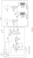
Figure 3 illustrates a hydraulic system for a header assembly according to an embodiment of the present disclosure. -
Figure 1 is a top perspective view of anexample header assembly 100. Theheader assembly 100 includes aheader 101 that may be removably coupled to an agricultural vehicle, for example a combine harvester or a forage harvester. Theheader 101 includes acutter bar 102 that extends across awidth 103 of theheader 101 betweenside portions header 101. When the agricultural vehicle is in operation, blades of thecutter bar 102 engage and cut crops. In this example, the portions of the crops that are cut may be directed onto aconveyor 108 of theheader 101 by a reel assembly (not shown). Theconveyor 108 includes afirst conveyor section 110 and asecond conveyor section 112. In general, theconveyor 108 is configured to transport cut crops toward aninlet 114. As an example, thefirst conveyor section 110 may direct the crops in afirst direction 116 toward acentre section 119, and thesecond conveyor section 112 may direct the crops in asecond direction 118 toward thecentre section 119. Thecentre section 119 may then direct the crops to theinlet 114 in athird direction 120 toward a crop processing system of the agricultural vehicle. Thefirst direction 116 and thesecond direction 118 can be considered as a longitudinal dimension of theheader 101. Thethird direction 120 can be considered as being in a transverse dimension of theheader 101. A fourth direction (not shown) can define a vertical dimension of theheader 101 which is perpendicular to a ground surface during operation of theheader 101. - The
header assembly 100 also includes afirst gauge wheel 122 and asecond gauge wheel 124 to facilitate movement of theheader 101 along the ground during operation. Thegauge wheels header 101. Thefirst gauge wheel 122 is positioned towards a first end of theheader 101, in other words between thecentre section 119 and thefirst side portion 104. Thesecond gauge wheel 124 is positioned towards a second end of theheader 101, in other words, between thecentre section 119 and thesecond side portion 106. In this way, the first and second ends are spaced apart from each in other in the longitudinal dimension of theheader 101. - It will be appreciated that other example headers are known and the invention is not limited to the example of
Figure 1 . For example, the header assembly may comprise an auger header or a corn header. -
Figures 2A and 2B illustrate a cross-sectional view of aheader assembly 200 for an agricultural vehicle according to an embodiment of the present disclosure. Features ofFigures 2A and 2B that are also present inFigure 1 have been given corresponding numbers in the 200 series and are not necessarily described again here. - The
header assembly 200 includes at least one gauge wheel assembly comprising agauge wheel 222.Figure 2A illustrates the gauge wheel assembly in an operating configuration andFigure 2B illustrates the gauge wheel assembly in a transport configuration. - The operating configuration defines a position of the gauge wheel assembly when the
header 201 is operating, i.e. processing crops. In the operating configuration, thegauge wheel 222 contacts aground surface 232 and supports at least a portion of the weight of theheader 201. In the operating configuration, a lower edge of thegauge wheel 222 may be positioned below alower surface 203 of theheader 201, such that thegauge wheel 222 supports the weight of theheader 201, when the header is oriented in a normal operating orientation (with the longitudinal dimension parallel to theground surface 232, as depicted inFigures 1 and2 ). Thelower surface 203 of theheader 201 may comprise a lower surface or lower edge of thecutter bar 202. The operating configuration may comprise thegauge wheel 222 extended towards theground surface 232 and/or away from theheader 201. It will be appreciated that the operating configuration may correspond to a range of positions (or range of configurations) of thegauge wheel 222 with a lower edge of thegauge wheel 222 below the lower surface 203 (or extended towards the ground surface 232). As described below, the range of positions enables variation of the position of the gauge wheel depending on properties of the process (e.g. required cut height), properties of the header (e.g. size, weight) and theground surface 232, e.g. soil moisture, compactness etc. - The transport configuration, shown in
Figure 2B , defines a storage position or transport position of thegauge wheel 222 and gauge wheel assembly during transport of the header. For example, between operations theheader assembly 200 may be detached from the agricultural vehicle and transported on a trailer or transported to a storage location using a fork etc. In the transport configuration, it can be advantageous for thegauge wheel 222 to not provide support to theheader 201 to avoid the header rolling around on a trailer or in storage. It is also advantageous for the header assembly to be more compact for transport by retracting the gauge wheel assembly towards a rear of theheader 201. In the transport configuration, thegauge wheel 222 is stowed in a transport position. In the transport configuration, the lower edge of thegauge wheel 222 may be positioned above thelower surface 203 of theheader 201, such that thegauge wheel 222 does not support the weight of theheader 201 when the header is oriented in the normal operating orientation. The transport configuration may comprise thegauge wheel 222 positioned adjacent to, or tucked in behind, a rear side of theheader 201 and/or retracted away from theground surface 232. Thegauge wheel 222 may be positioned further from a rear of theheader 201 and closer to theground surface 232 in the operating configuration than in the transport configuration. - As shown in
Figures 2A and 2B , the gauge wheel assembly includes thegauge wheel 222 and acoupling mechanism 226 for coupling thegauge wheel 222 to theheader 201. Thecoupling mechanism 226 includes ahydraulic cylinder 230. Thehydraulic cylinder 230 in this example couples theheader 201 to thegauge wheel 222. Thehydraulic cylinder 230 is configured to selectively extend from a retracted configuration towards an extended configuration to urge the lower edge of thegauge wheel 222 below and away from thelower surface 203 of theheader 201. Thecoupling mechanism 226 further includes a biasingelement 228. In this example the biasingelement 228 is a coiled spring. The biasingelement 228 is arranged to bias thehydraulic cylinder 230 towards the retracted configuration. - The arrangement of the
coupling mechanism 226 advantageously allows: (i) selective transition of the gauge wheel assembly from the transport configuration to the operating configuration by selectively applying pressure to thehydraulic cylinder 230; and (ii) automatic return of the gauge wheel assembly to the transport position when pressure is selectively removed form thehydraulic cylinder 230 and the bias of the biasingelement 228 retracts thehydraulic cylinder 230. - The retracted configuration of the
hydraulic cylinder 230 may correspond to the transport configuration of the gauge wheel assembly. In other words, when the hydraulic cylinder is in the retracted configuration, thecoupling mechanism 226 /hydraulic cylinder 230 may position the gauge wheel assembly in the transport position. - As noted above, the operating configuration of the gauge wheel assembly may correspond to a range of gauge wheel positions. The extended configuration of the
hydraulic cylinder 230 may refer to a complete extension of the hydraulic cylinder 230 (which may be limited by a mechanical stop). In such examples, the operating configuration may correspond to any extension of thehydraulic cylinder 230, other than the retracted configuration, that provides the lower edge of thegauge wheel 222 below thelower surface 203 of theheader 201. By extending from the retracted configuration towards the extended configuration, the coupling mechanism /hydraulic cylinder 230 may urge the gauge wheel assembly into the operating configuration. - Selective extension of the hydraulic cylinder towards the extended configuration may be provided by selectively applying a pressure to the hydraulic cylinder, resulting in an extension force. In this way, the
hydraulic cylinder 230 may selectively apply the extension force to urge the gauge wheel assembly into the operating configuration. - The biasing element may provide a biasing force to urge the
hydraulic cylinder 230 to the retracted configuration (and the gauge wheel assembly into the transport position). The biasing force may be in the opposite direction to the extension force. The biasing force may vary depending on a compression state or extension state of the biasing element (e.g. for a spring). The biasing force may have a minimum value (a retracted biasing force) when thehydraulic cylinder 230 is in the retracted configuration and may increase as the hydraulic cylinder extends towards the extended configuration (to an extended biasing force). The extension force may be set to an appropriate value greater than the retracted biasing force. As a result, when thehydraulic cylinder 230 selectively extends and applies the extension force, the gauge wheel assembly moves into the operating configuration because the extension force overcomes the biasing force of the biasingelement 228. Thehydraulic cylinder 230 may continue to extend towards the extended configuration until either: (i) a sum of the (potentially increasing) biasing force and any ground reaction force (resulting from contact of thegauge wheel 222 with the ground surface 232) balances the extension force; or (ii) the hydraulic cylinder reaches the extended configuration (which may be limited by a mechanical stop). - In some examples, the
gauge wheel 232 contacts theground surface 232 and the hydraulic cylinder 230 (and gauge wheel assembly) continues to extend until a sum of the ground reaction force and the biasing force equals the extension force. Therefore, adjusting the extension force can adjust a total extension of thecylinder 230 / gauge wheel assembly and a clearance height of theheader 201 from theground surface 232. When thehydraulic cylinder 230 does not apply the extension force, the biasing force retracts thehydraulic cylinder 230 to the retracted configuration and the gauge wheel assembly returns to the transport configuration. In this way, selective activation of thehydraulic cylinder 230 can: (i) move the hydraulic cylinder from the retracted configuration towards the extended configuration; and (ii) move the gauge wheel assembly from the transport configuration to the operating configuration. Similarly, selective deactivation of thehydraulic cylinder 230 can automatically: (i) move thehydraulic cylinder 230 away from the extended configuration and towards the retracted configuration; and (ii) move the gauge wheel assembly from the operating configuration to the transport configuration. - In this example, the gauge wheel assembly also includes a connecting
arm 234. A first end of the connectingarm 234 is pivotally connected to theheader 201 at apivot point 236. A second end of the connectingarm 234 connects to thegauge wheel 222. The biasingelement 228 is connected between theheader 201 and a biasingelement connection point 235 on the connectingarm 234. Thehydraulic cylinder 230 extends between theheader 201 and ahydraulic connection point 237 on the connectingarm 234. In this example, the biasingelement connection point 235 and thehydraulic connection point 237 are located between the first and second ends of the connectingarm 234. It will be appreciated that other arrangements are possible for connecting the biasingelement 228 and thehydraulic cylinder 230 between theheader 201 and thefirst gauge wheel 222. For example, the connectingarm 234 may be omitted and the biasingelement 228 and thehydraulic cylinder 230 may connect directly to thegauge wheel 222. In some examples, the biasingelement 228 may be housed within thehydraulic cylinder 230 and arranged to urge thehydraulic cylinder 230 towards the retracted configuration and thegauge wheel assembly 222 towards the transport configuration. - In
Figure 2A , a hydraulic system (discussed below) applies pressure to thehydraulic cylinder 230 such that thecylinder 230 extends towards the extended configuration and applies an extension force to thegauge wheel 222 that is greater than the retracted biasing force of the biasingelement 228. As a result, the connectingarm 234 of the gauge wheel assembly pivots the assembly into the operating configuration such that thegauge wheel 222 contacts theground surface 232. - In
Figure 2B , the hydraulic system discharges pressure from thehydraulic cylinder 230 thereby removing the extension force. The biasing force of the biasingelement 228 retracts thehydraulic cylinder 230 to the retracted configuration and thegauge wheel assembly 222 pivots into the transport configuration. - The
header assembly 200 may comprise a pair of gauge wheel assemblies. For example, theheader assembly 200 may include a first gauge wheel assembly positioned at (or towards) a first end of theheader 201 and a second gauge wheel assembly position at (or towards) a second end of theheader 201, wherein the first and second ends are separated along the longitudinal dimension of the header (as illustrated inFigure 1 ). Headers can be wide in the longitudinal dimension (e.g. 40 metres). Providing two gauge wheel assemblies (or more), with one at each end of theheader 201, can enable theheader assembly 200 to remain level when there is anuneven ground surface 232 across the long width of theheader 201 in the longitudinal dimension. As discussed below, the extension force may be provided by applying and maintaining a fixed pressure in thehydraulic cylinder 230 of each gauge wheel assembly. By maintaining a fixed pressure in thehydraulic cylinder 230, eachhydraulic cylinder 230 / gauge wheel assembly will retract or extend in response to bumps or dips in theground surface 232 due to the corresponding variation in ground reaction force. As a result, theheader 201 can maintain a fixed clearance height above theground surface 232 across the width of theheader 201. This advantageously avoids an end of theheader 201 digging into theground surface 232, which can result in damage to theheader 201 and/or soil contamination in the harvested crop. - The
header assembly 200 may include a hydraulic system for selectively applying the extension force to thehydraulic cylinder 230.Figure 3 illustrates an examplehydraulic system 334 according to an embodiment of the present disclosure. The illustratedhydraulic system 334 is for a header assembly including two gauge wheel assemblies, such as the header assembly ofFigure 1 . - The
hydraulic system 334 is configured to selectively provide, and maintain, a fixed pressure (which may be referred to as a fixed pressure value) to both a first hydraulic cylinder 330 (of a first gauge wheel assembly) and a second hydraulic cylinder 336 (of a second gauge wheel assembly). In this example, chambers of the first and secondhydraulic cylinders first biasing element 328 andsecond biasing element 338. - In this example, the
hydraulic system 334 comprises a charge/discharge module 335 and acylinder control module 337. The charge/discharge module 335 comprises asystem input 350 for coupling to a hydraulic pump or reservoir (not shown). The pump and reservoir may form part of a separate hydraulic system such as a hydraulic system of the agricultural vehicle. Thesystem input 350 is connected to aninput 351 of a pressure set-point control valve 352. An output of the pressure set-point control valve 352 is connected to a two-position valve 342 via arelief valve 354. An output of the two-position valve 342 connects to asupply line 360 of thecylinder control module 337. - The
cylinder control module 337 comprises the firsthydraulic cylinder 330 and the secondhydraulic cylinder 336. A chamber end of each of the first and secondhydraulic cylinders supply line 360. In this example, thecylinder control module 337 further comprises afirst accumulator 356 for controlling a pressure of the firsthydraulic cylinder 328 and asecond accumulator 358 for controlling a pressure of the secondhydraulic cylinder 338. The first andsecond accumulators supply line 360 proximal or close to (within a threshold distance of) the respective first and secondhydraulic cylinders accumulator hydraulic cylinder first accumulator 356 and the firsthydraulic cylinder 330 will be co-located at a first end of the header (with the first gauge wheel assembly) and the second accumulator and secondhydraulic cylinder 336 will be co-located at the second end of the header (with the second gauge wheel assembly). As headers are typically tens of meters long, each of the first andsecond accumulators hydraulic cylinders hydraulic cylinders hydraulic cylinders hydraulic cylinder second accumulators supply line 360 by a respective first and second oneway restriction valve hydraulic cylinders respective accumulator first accumulator 356 from the secondhydraulic cylinder 338, and of thesecond accumulator 358 from the firsthydraulic cylinder 330. It will be appreciated that further variations are possible. For example, with reference to the illustrated example, in some example, thefirst accumulator 356 may not be directly connected to thesupply line 360 and instead be connected to a line connecting thesupply line 360 to the firsthydraulic cylinder 330. Such an arrangement can improve isolation of thefirst accumulator 356 from the secondhydraulic cylinder 338, and of thesecond accumulator 358 from the firsthydraulic cylinder 330. - In this example a
controller 340 controls thehydraulic system 334. Thecontroller 340 configures thehydraulic system 334 /hydraulic cylinders controller 340 may form part of thehydraulic system 334, the header assembly, the agricultural vehicle or its functionality may be distributed across two or more of thehydraulic system 334, the header assembly and the agricultural vehicle. - The
hydraulic system 334 may include one or more sensors for monitoring a state of thehydraulic system 334. Thehydraulic system 334 may comprise one or more pressure sensors (not shown) for indicating a pressure in thehydraulic system 334 and/or one ormore position sensors hydraulic cylinders point control valve 352 and/or may be positioned in thecylinder control module 337, for example a pressure sensor may be positioned in the chamber of one or bothhydraulic cylinders second position sensors hydraulic cylinder controller 340 may receive sensor signals from the one or more sensors to monitor the state of thehydraulic system 334. - Operation of the hydraulic system and gauge wheel assembly will be described with reference to four phases: (i) transition of gauge wheel assemblies from the transport configuration to the operating configuration; (ii) operation of the header with the gauge wheel assemblies in the operating configuration; (iii) adjustment of the fixed pressure value / header height; and (iv) transition of the gauge wheel assemblies from the operating configuration to the transport configuration.
- In the first phase, the gauge wheel assemblies are initially in the transport configuration, with the first and second
hydraulic cylinders hydraulic system 334 and therefore no extension force is applied to eitherhydraulic cylinder elements hydraulic cylinders position valve 342 resides in a (default) closedposition 348 which isolates thecylinder control module 337. - At a first time, for example when an operator has connected the header assembly to the agricultural vehicle and is ready to begin harvesting, the
controller 340 sets the two-position valve 342 of thehydraulic system 334 into anopen position 344. Thecontroller 340 may set the two-position valve in response to an enable signal, EN, received from a user input, for example from an operator control unit in an operator cab of the agricultural vehicle. The controller may set the two-position valve 342 in response to the enable signal, EN, and a sensor signal from the one or more sensors indicating that the pressure is less than the fixed pressure value (e.g. a pressure signal from a pressure sensor in thecylinder control module 337 or a position signal from aposition sensor cylinders - In this example, the
controller 340 sets the two-position valve 342 into theopen position 344 by actuating asolenoid 346 of the two-position valve 342. In other examples, an operator may manually actuate the two-position valve 342, for example via a pedal or lever in the cab of the agricultural vehicle. In response to the enable signal, EN, (and the sensor signal) thecontroller 340 may also activate a pump (not shown) connected to theinput 350 of thehydraulic system 340. Activation of the pump may comprise supplying power to the pump and/or controlling a switch to connect the pump to theinput 350 of the hydraulic system. The pump applies pressure to thehydraulic system 334 and charges thehydraulic system 334. - In this example, the
hydraulic system 334 includes the pressure set-point control valve 352 for controlling a value of the fixed pressure (100 bar in this example). The pressure set-point control valve 352 may comprise a pressure reducing valve. A pressure set-point of the pressure set-point control valve 352 may be set to the fixed pressure value (or a value offset from the fixed pressure value to allow for any pressure drop along the supply line 360). Initially, with thehydraulic system 334 at low pressure, the pump increases the pressure in thehydraulic system 334. Once the pressure at theinput 351 of the pressure set-point control valve 352 reaches the pressure set-point, the pressure set-point control valve 352 fixes the pressure at theoutput 353 of the pressure set-point control valve 352 to the pressure set-point, irrespective of a further increase in pressure at theinput 351. As a result, the pressure set-point control valve 352 sets a fixed pressure in thecylinder control module 337 and theaccumulators - As the pressure in the
hydraulic system 334 increases, the extension force of thehydraulic cylinders respective biasing element hydraulic cylinders hydraulic system 334 reaches the fixed pressure value, a fixed extension force extends the gauge wheel assemblies until the sum of the biasing force and any ground reaction force equal the extension force. - In this example, the
hydraulic system 334 comprises arelief valve 354 connecting theoutput 353 of the pressure set-point control valve 352 to the two-position valve 342. Therelief valve 354 comprises a restriction that dampens the rate of the pressure increase in thecylinder control module 337 and thereby the rate at which thehydraulic cylinders - In response to the one or more sensor signals indicating that the
cylinder control module 337 has reached the fixed pressure value and thehydraulic cylinders position valve 342 to theclosed position 348, isolating thecylinder control module 337 from the rest of thehydraulic system 334. The controller may deactivate the pump and/or may disconnect the pump from thehydraulic system 334. - In the second phase, the gauge wheel assemblies are maintained in the operating configuration as the agricultural vehicle processes crops with the
header assembly 201. As the two-position valve 342 is in the closed position, the cylinder control module is isolated from the rest of thehydraulic system 334 and has a pressure equal to the fixed pressure value. - With the
cylinder control unit 337 isolated at the fixed pressure value (which may be adjusted as described above), the first andsecond accumulators second restriction valves hydraulic cylinders hydraulic cylinder - In the third phase, a height of the header may be adjusted. The pressure set-
point control valve 352 may be an adjustable valve, for example, such that the pressure set-point control valve 352 may be an adjustable pressure relief valve. To adjust the fixed pressure value to a new fixed pressure value, thecontroller 340 may set the two-position valve 342 to theopen position 344 and output a pressure set-point signal to adjust the pressure set point of the pressure set-point control valve 352 to correspond to the new fixed pressure value. Thecontroller 340 may then set the two-position valve 342 to theclosed position 348. Thecontroller 340 may set the two-position valve 342 to theclosed position 348 in response to one or more sensor signals indicating that thehydraulic system 334 has adjusted to the new fixed pressure value. Adjusting the fixed pressure value will adjust the clearance height of the header due to the corresponding adjustment to the extension force in thehydraulic cylinders - In some examples, the
controller 340 may receive a height-setting-signal, for example from a user interface in the operator cab of the agricultural vehicle. In some examples, the height-setting-signal may comprise a header height set-point. In examples employing one ormore position sensors controller 340 may determine the clearance height of the header based on the position sensor signal from the one ormore position sensors controller 340 may determine the clearance height by averaging the position sensor signal over a fixed time period which can allow for an uneven ground surface. Thecontroller 340 may output the pressure set-point signal to adjust the pressure set-point of the pressure set-point control valve 352 until the clearance height indicated by the position sensor signals from the one or more position sensors equals the header height set-point. - In examples not including a
position sensor controller 340 may calculate the pressure set-point or the fixed pressure value based on the header height set-point. For example, thecontroller 340 may use a look-up table or a known relationship between the pressure set-point / fixed pressure value and the clearance height of the header to calculate the pressure set-point from the header height set-point. Thecontroller 340 may calculate the pressure set-point or the fixed pressure value based on one or more further parameters including soil condition, header type, header weight etc. In some examples, the height-setting-signal can comprise the pressure set-point or the fixed pressure value. The controller may calculate or receive the pressure set-point and output the pressure set-point signal accordingly. Thecontroller 340 may calculate or receive the fixed pressure value and output the pressure set-point signal to adjust the pressure set-point control valve 352 until a pressure sensor signal from the one or more pressure signals indicates a pressure equal to the fixed pressure value. - In some examples, the
controller 340 may output a height-indication-signal, for example thecontroller 340 may output a height-indication signal to the operator cab of the agricultural vehicle for display on a display screen or meter of the operator cab. The height-indication-signal may comprise one or more of: the fixed pressure value as indicated by the one or more pressure sensors; the pressure set-point; and the clearance height of the header. The clearance height of the header may be determined based on the position sensor signal from the one ormore position sensors - The fourth phase may correspond to the end of crop processing, when the operator is ready to remove the header from the agricultural vehicle. The enable signal, EN, may be set low or removed, for example the operator control unit in the operator cab of the agricultural vehicle may set the enable signal low in response to a command from the operator. In response, the
controller 340 may set the two-position valve 342 to theopen position 344 and connect theinput 350 of thehydraulic system 334 to a reservoir / drain. As a result, pressure is discharged from thecylinder control module 337 and the extension force is removed. The biasing force of the biasingelements hydraulic cylinders - Throughout the present specification, the descriptors relating to relative orientation and position, such as "horizontal", "vertical", "top", "bottom" and "side", are used in the sense of the orientation of the header and header assembly as presented in the drawings. However, such descriptors are not intended to be in any way limiting to an intended use of the described or claimed invention.
- It will be appreciated that any reference to "close to", "before", "shortly before", "after" "shortly after", "higher than", or "lower than", etc, can refer to the parameter in question being less than or greater than a threshold value, or between two threshold values, depending upon the context.
Claims (15)
- A header assembly (200) for an agricultural vehicle, the header assembly comprising:a header (201) comprising a lower surface (203); andat least one gauge wheel assembly comprising:a gauge wheel (222); anda coupling mechanism (226) coupling the gauge wheel (222) to the header (201), the coupling mechanism including:a hydraulic cylinder (230) configured to selectively extend from a retracted configuration towards an extended configuration to urge a lower edge of the gauge wheel (222) below and away from the lower surface of the header (203); anda biasing element (228) arranged to bias the hydraulic cylinder (230) to the retracted configuration.
- The header assembly (200) of claim 1, wherein the biasing element (228) is arranged to bias the hydraulic cylinder (230) to the retracted configuration in the absence of the selective extension.
- The header assembly (200) of claim 1 or claim 2, further comprising a hydraulic system (334) configured to selectively provide a fixed pressure to the hydraulic cylinder (230, 330) to selectively extend the hydraulic cylinder towards the extended configuration.
- The header assembly (200) of claim 3, wherein the hydraulic system (334) comprises at least one accumulator (356, 358) for charging to the fixed pressure, such that the at least one accumulator maintains the fixed pressure in the hydraulic cylinder (230, 330).
- The header assembly (200) of claim 4, wherein the hydraulic system (334) comprises a two-position valve (342) for selectively isolating the at least one accumulator (356, 358) and the hydraulic cylinder (230, 330) from the rest of the hydraulic system (334).
- The header assembly (200) of any of claims 3 to 5, wherein the hydraulic system (334) comprises a pressure set-point control valve (352) configured to set a value of the fixed pressure.
- The header assembly (200) of any of claim 5 or claim 6, wherein the header assembly further comprises a controller (340), wherein the controller is configured to:receive a height setting signal; andoutput a pressure set-point signal for setting a pressure set-point of the pressure set point control valve (352), based on the height setting signal.
- The header assembly (200) of claim 7, further comprising a position sensor for monitoring an extension of the hydraulic cylinder (230, 330), wherein the height setting signal comprises a height set-point and the controller (340) is configured to:receive a position sensor signal from the position sensor;output the pressure set-point signal to adjust the pressure set-point until the position sensor signal indicates an extension of the hydraulic cylinder (230, 330) corresponding to the height set-point.
- The header assembly (200) of claim 7, wherein the height setting signal comprises a height set point and the controller (340) is configured to:calculate the pressure set-point based on the height set-point and a predetermined relationship between the pressure set point and the height set point; andoutput the pressure set-point signal to the pressure set-point control valve (352) based on the calculated pressure set-point.
- The header assembly (200) of claim 7, further comprising a pressure sensor for monitoring the value of the fixed pressure, wherein the height setting signal comprises a height set point and the controller (340) is configured to:calculate the value of the fixed pressure based on the height set-point and a predetermined relationship between the value of the fixed pressure and the height set point;receive a pressure sensor signal from the pressure sensor; andoutput the pressure set-point signal to adjust the pressure set-point until the pressure sensor signal indicates a pressure corresponding to the value of the fixed pressure.
- The header assembly (200) of any of claims 7 to 10, wherein the header assembly comprises a two-position valve (342) arranged to selectively couple the pressure set-point control valve (352) to the at least one accumulator (356, 358) and the hydraulic cylinder (230, 330), wherein the controller (340) is configured to:Control the two-position valve (342) to couple the pressure set-point control valve (352) to the at least one accumulator (356, 358) and the hydraulic cylinder (230, 330); andcontrol the two-position valve (342) to isolate the pressure set-point control valve (352) from the at least one accumulator (356, 358) and the hydraulic cylinder 230, 330).
- The header assembly (200) of any preceding claim, further comprising at least one sensor, wherein the at least one sensor comprises:a position sensor for sensing an extension of the hydraulic cylinder (230, 330); andone or more pressure sensors for sensing a pressure of the hydraulic system (334).
- The header assembly (200) of claim 12, further comprising a controller (340) configured to output a height indication signal based on a sensor signal from the at least one sensor.
- The header assembly (200) of any preceding claim, wherein the at least one gauge wheel assembly comprises a first gauge wheel assembly positioned at a first end of the header (201) and a second gauge wheel assembly positioned at a second end of the header, opposite the first end.
- The header assembly (200) of claim 14, wherein the at least one accumulator comprises a first accumulator (356) for maintaining a fixed pressure in the hydraulic cylinder (230, 330) of the first gauge wheel assembly and a second accumulator (358) for maintaining a fixed pressure in the hydraulic cylinder (336) of the second gauge wheel assembly.
Priority Applications (3)
| Application Number | Priority Date | Filing Date | Title |
|---|---|---|---|
| EP22217048.2A EP4393292B1 (en) | 2022-12-28 | 2022-12-28 | Header assembly for an agricultural vehicle |
| CN202311566601.4A CN118252027A (en) | 2022-12-28 | 2023-11-22 | Harvesting header assemblies for agricultural vehicles |
| US18/393,791 US20240215485A1 (en) | 2022-12-28 | 2023-12-22 | Header assembly for an agricultural vehicle |
Applications Claiming Priority (1)
| Application Number | Priority Date | Filing Date | Title |
|---|---|---|---|
| EP22217048.2A EP4393292B1 (en) | 2022-12-28 | 2022-12-28 | Header assembly for an agricultural vehicle |
Publications (2)
| Publication Number | Publication Date |
|---|---|
| EP4393292A1 true EP4393292A1 (en) | 2024-07-03 |
| EP4393292B1 EP4393292B1 (en) | 2025-10-08 |
Family
ID=84689164
Family Applications (1)
| Application Number | Title | Priority Date | Filing Date |
|---|---|---|---|
| EP22217048.2A Active EP4393292B1 (en) | 2022-12-28 | 2022-12-28 | Header assembly for an agricultural vehicle |
Country Status (3)
| Country | Link |
|---|---|
| US (1) | US20240215485A1 (en) |
| EP (1) | EP4393292B1 (en) |
| CN (1) | CN118252027A (en) |
Families Citing this family (1)
| Publication number | Priority date | Publication date | Assignee | Title |
|---|---|---|---|---|
| BR112022026897A2 (en) * | 2020-06-30 | 2023-01-24 | Cnh Ind America Llc | CALIBRATOR WHEEL CONTROL SYSTEM FOR AN AGRICULTURAL SYSTEM |
Citations (5)
| Publication number | Priority date | Publication date | Assignee | Title |
|---|---|---|---|---|
| EP2156725A2 (en) * | 2008-08-22 | 2010-02-24 | Deere & Company | Header float system for use with an agricultural windrower or combine |
| US7971420B1 (en) * | 2010-08-31 | 2011-07-05 | Deere & Company | Draper platform suspension |
| US20190200523A1 (en) * | 2018-01-04 | 2019-07-04 | CNH Industrial America, LLC | Draper header for harvester and methods of using the same |
| US20210153434A1 (en) * | 2019-11-26 | 2021-05-27 | Cnh Industrial America Llc | Header float system for use with an agricultural windrower or combine |
| WO2022006280A1 (en) * | 2020-06-30 | 2022-01-06 | Cnh Industrial America Llc | Gauge wheel control system for an agricultural system |
Family Cites Families (4)
| Publication number | Priority date | Publication date | Assignee | Title |
|---|---|---|---|---|
| US4422511A (en) * | 1979-03-30 | 1983-12-27 | Erhard Poggemiller | Hydraulic reset for tillage and seeding equipment |
| US7673570B1 (en) * | 2008-12-01 | 2010-03-09 | Dawn Equipment Company | Row-clearing unit for agricultural implement |
| US9148998B2 (en) * | 2012-08-11 | 2015-10-06 | Deere & Company | Header height control system |
| US11246259B2 (en) * | 2019-04-26 | 2022-02-15 | Deere & Company | Locking assembly for agricultural combine harvesting head |
-
2022
- 2022-12-28 EP EP22217048.2A patent/EP4393292B1/en active Active
-
2023
- 2023-11-22 CN CN202311566601.4A patent/CN118252027A/en active Pending
- 2023-12-22 US US18/393,791 patent/US20240215485A1/en active Pending
Patent Citations (5)
| Publication number | Priority date | Publication date | Assignee | Title |
|---|---|---|---|---|
| EP2156725A2 (en) * | 2008-08-22 | 2010-02-24 | Deere & Company | Header float system for use with an agricultural windrower or combine |
| US7971420B1 (en) * | 2010-08-31 | 2011-07-05 | Deere & Company | Draper platform suspension |
| US20190200523A1 (en) * | 2018-01-04 | 2019-07-04 | CNH Industrial America, LLC | Draper header for harvester and methods of using the same |
| US20210153434A1 (en) * | 2019-11-26 | 2021-05-27 | Cnh Industrial America Llc | Header float system for use with an agricultural windrower or combine |
| WO2022006280A1 (en) * | 2020-06-30 | 2022-01-06 | Cnh Industrial America Llc | Gauge wheel control system for an agricultural system |
Also Published As
| Publication number | Publication date |
|---|---|
| CN118252027A (en) | 2024-06-28 |
| EP4393292B1 (en) | 2025-10-08 |
| US20240215485A1 (en) | 2024-07-04 |
Similar Documents
| Publication | Publication Date | Title |
|---|---|---|
| US7661251B1 (en) | Header float system for use with an agricultural windrower or combine | |
| EP3735123B1 (en) | Draper header for harvester | |
| US7430846B2 (en) | Floating header with integrated float system for use with an agricultural windrower or combine | |
| AU2012241157B2 (en) | Header height control with tire flex compensation | |
| US7287365B2 (en) | Baler | |
| CA2624556C (en) | Floating header with integrated float system for use with an agricultural windrower or combine | |
| CA2796131C (en) | Crop harvesting machine with calibration of the header float springs | |
| EP1721508B1 (en) | Header hydraulic float suspension | |
| US20220053693A1 (en) | Ground pressure feedback sensor system for controlling header float | |
| EP1721509A2 (en) | Header terrain following system | |
| EP1721507A1 (en) | Header hydraulic float system | |
| EA027650B1 (en) | Header height control system | |
| US11606910B2 (en) | Crop throughput sensing system for a harvesting machine | |
| US20240215485A1 (en) | Header assembly for an agricultural vehicle | |
| WO2024159301A1 (en) | Systems and methods for maintaining desired accumulator pressure based on cylinder positions | |
| BR102023027422A2 (en) | PLATFORM ASSEMBLY FOR AN AGRICULTURAL VEHICLE | |
| US20250234806A1 (en) | Apparatus and method for adjusting an agricultural header based on a sensed crop load |
Legal Events
| Date | Code | Title | Description |
|---|---|---|---|
| PUAI | Public reference made under article 153(3) epc to a published international application that has entered the european phase |
Free format text: ORIGINAL CODE: 0009012 |
|
| STAA | Information on the status of an ep patent application or granted ep patent |
Free format text: STATUS: THE APPLICATION HAS BEEN PUBLISHED |
|
| AK | Designated contracting states |
Kind code of ref document: A1 Designated state(s): AL AT BE BG CH CY CZ DE DK EE ES FI FR GB GR HR HU IE IS IT LI LT LU LV MC ME MK MT NL NO PL PT RO RS SE SI SK SM TR |
|
| STAA | Information on the status of an ep patent application or granted ep patent |
Free format text: STATUS: REQUEST FOR EXAMINATION WAS MADE |
|
| 17P | Request for examination filed |
Effective date: 20250103 |
|
| GRAP | Despatch of communication of intention to grant a patent |
Free format text: ORIGINAL CODE: EPIDOSNIGR1 |
|
| STAA | Information on the status of an ep patent application or granted ep patent |
Free format text: STATUS: GRANT OF PATENT IS INTENDED |
|
| INTG | Intention to grant announced |
Effective date: 20250611 |
|
| GRAS | Grant fee paid |
Free format text: ORIGINAL CODE: EPIDOSNIGR3 |
|
| GRAA | (expected) grant |
Free format text: ORIGINAL CODE: 0009210 |
|
| STAA | Information on the status of an ep patent application or granted ep patent |
Free format text: STATUS: THE PATENT HAS BEEN GRANTED |
|
| AK | Designated contracting states |
Kind code of ref document: B1 Designated state(s): AL AT BE BG CH CY CZ DE DK EE ES FI FR GB GR HR HU IE IS IT LI LT LU LV MC ME MK MT NL NO PL PT RO RS SE SI SK SM TR |
|
| REG | Reference to a national code |
Ref country code: GB Ref legal event code: FG4D Ref country code: CH Ref legal event code: F10 Free format text: ST27 STATUS EVENT CODE: U-0-0-F10-F00 (AS PROVIDED BY THE NATIONAL OFFICE) Effective date: 20251008 |
|
| REG | Reference to a national code |
Ref country code: DE Ref legal event code: R096 Ref document number: 602022022633 Country of ref document: DE |
|
| REG | Reference to a national code |
Ref country code: IE Ref legal event code: FG4D |
|
| PGFP | Annual fee paid to national office [announced via postgrant information from national office to epo] |
Ref country code: AT Payment date: 20260113 Year of fee payment: 4 |
|
| PGFP | Annual fee paid to national office [announced via postgrant information from national office to epo] |
Ref country code: FR Payment date: 20251223 Year of fee payment: 4 |
|
| REG | Reference to a national code |
Ref country code: NL Ref legal event code: MP Effective date: 20251008 |
|
| REG | Reference to a national code |
Ref country code: AT Ref legal event code: MK05 Ref document number: 1844048 Country of ref document: AT Kind code of ref document: T Effective date: 20251008 |
|
| PG25 | Lapsed in a contracting state [announced via postgrant information from national office to epo] |
Ref country code: NL Free format text: LAPSE BECAUSE OF FAILURE TO SUBMIT A TRANSLATION OF THE DESCRIPTION OR TO PAY THE FEE WITHIN THE PRESCRIBED TIME-LIMIT Effective date: 20251008 |
|
| PG25 | Lapsed in a contracting state [announced via postgrant information from national office to epo] |
Ref country code: ES Free format text: LAPSE BECAUSE OF FAILURE TO SUBMIT A TRANSLATION OF THE DESCRIPTION OR TO PAY THE FEE WITHIN THE PRESCRIBED TIME-LIMIT Effective date: 20251008 |
|
| REG | Reference to a national code |
Ref country code: LT Ref legal event code: MG9D |
|
| PG25 | Lapsed in a contracting state [announced via postgrant information from national office to epo] |
Ref country code: NO Free format text: LAPSE BECAUSE OF FAILURE TO SUBMIT A TRANSLATION OF THE DESCRIPTION OR TO PAY THE FEE WITHIN THE PRESCRIBED TIME-LIMIT Effective date: 20260108 |
|
| PGFP | Annual fee paid to national office [announced via postgrant information from national office to epo] |
Ref country code: DE Payment date: 20251229 Year of fee payment: 4 |
|
| PG25 | Lapsed in a contracting state [announced via postgrant information from national office to epo] |
Ref country code: HR Free format text: LAPSE BECAUSE OF FAILURE TO SUBMIT A TRANSLATION OF THE DESCRIPTION OR TO PAY THE FEE WITHIN THE PRESCRIBED TIME-LIMIT Effective date: 20251008 Ref country code: AT Free format text: LAPSE BECAUSE OF FAILURE TO SUBMIT A TRANSLATION OF THE DESCRIPTION OR TO PAY THE FEE WITHIN THE PRESCRIBED TIME-LIMIT Effective date: 20251008 Ref country code: FI Free format text: LAPSE BECAUSE OF FAILURE TO SUBMIT A TRANSLATION OF THE DESCRIPTION OR TO PAY THE FEE WITHIN THE PRESCRIBED TIME-LIMIT Effective date: 20251008 |
|
| PGFP | Annual fee paid to national office [announced via postgrant information from national office to epo] |
Ref country code: IT Payment date: 20251231 Year of fee payment: 4 |
|
| PG25 | Lapsed in a contracting state [announced via postgrant information from national office to epo] |
Ref country code: RS Free format text: LAPSE BECAUSE OF FAILURE TO SUBMIT A TRANSLATION OF THE DESCRIPTION OR TO PAY THE FEE WITHIN THE PRESCRIBED TIME-LIMIT Effective date: 20260108 |
|
| PG25 | Lapsed in a contracting state [announced via postgrant information from national office to epo] |
Ref country code: IS Free format text: LAPSE BECAUSE OF FAILURE TO SUBMIT A TRANSLATION OF THE DESCRIPTION OR TO PAY THE FEE WITHIN THE PRESCRIBED TIME-LIMIT Effective date: 20260208 |
|
| PG25 | Lapsed in a contracting state [announced via postgrant information from national office to epo] |
Ref country code: PT Free format text: LAPSE BECAUSE OF FAILURE TO SUBMIT A TRANSLATION OF THE DESCRIPTION OR TO PAY THE FEE WITHIN THE PRESCRIBED TIME-LIMIT Effective date: 20260209 |
|
| PG25 | Lapsed in a contracting state [announced via postgrant information from national office to epo] |
Ref country code: PL Free format text: LAPSE BECAUSE OF FAILURE TO SUBMIT A TRANSLATION OF THE DESCRIPTION OR TO PAY THE FEE WITHIN THE PRESCRIBED TIME-LIMIT Effective date: 20251008 |
|
| PG25 | Lapsed in a contracting state [announced via postgrant information from national office to epo] |
Ref country code: LV Free format text: LAPSE BECAUSE OF FAILURE TO SUBMIT A TRANSLATION OF THE DESCRIPTION OR TO PAY THE FEE WITHIN THE PRESCRIBED TIME-LIMIT Effective date: 20251008 |
|
| PG25 | Lapsed in a contracting state [announced via postgrant information from national office to epo] |
Ref country code: BG Free format text: LAPSE BECAUSE OF FAILURE TO SUBMIT A TRANSLATION OF THE DESCRIPTION OR TO PAY THE FEE WITHIN THE PRESCRIBED TIME-LIMIT Effective date: 20251008 |
|
| PG25 | Lapsed in a contracting state [announced via postgrant information from national office to epo] |
Ref country code: RO Free format text: LAPSE BECAUSE OF FAILURE TO SUBMIT A TRANSLATION OF THE DESCRIPTION OR TO PAY THE FEE WITHIN THE PRESCRIBED TIME-LIMIT Effective date: 20251008 |
|
| PG25 | Lapsed in a contracting state [announced via postgrant information from national office to epo] |
Ref country code: LT Free format text: LAPSE BECAUSE OF FAILURE TO SUBMIT A TRANSLATION OF THE DESCRIPTION OR TO PAY THE FEE WITHIN THE PRESCRIBED TIME-LIMIT Effective date: 20251008 |
|
| PG25 | Lapsed in a contracting state [announced via postgrant information from national office to epo] |
Ref country code: SM Free format text: LAPSE BECAUSE OF FAILURE TO SUBMIT A TRANSLATION OF THE DESCRIPTION OR TO PAY THE FEE WITHIN THE PRESCRIBED TIME-LIMIT Effective date: 20251008 |
|
| PG25 | Lapsed in a contracting state [announced via postgrant information from national office to epo] |
Ref country code: MC Free format text: LAPSE BECAUSE OF FAILURE TO SUBMIT A TRANSLATION OF THE DESCRIPTION OR TO PAY THE FEE WITHIN THE PRESCRIBED TIME-LIMIT Effective date: 20251008 |
|
| PG25 | Lapsed in a contracting state [announced via postgrant information from national office to epo] |
Ref country code: DK Free format text: LAPSE BECAUSE OF FAILURE TO SUBMIT A TRANSLATION OF THE DESCRIPTION OR TO PAY THE FEE WITHIN THE PRESCRIBED TIME-LIMIT Effective date: 20251008 |
|
| PG25 | Lapsed in a contracting state [announced via postgrant information from national office to epo] |
Ref country code: EE Free format text: LAPSE BECAUSE OF FAILURE TO SUBMIT A TRANSLATION OF THE DESCRIPTION OR TO PAY THE FEE WITHIN THE PRESCRIBED TIME-LIMIT Effective date: 20251008 |
|
| PG25 | Lapsed in a contracting state [announced via postgrant information from national office to epo] |
Ref country code: CZ Free format text: LAPSE BECAUSE OF FAILURE TO SUBMIT A TRANSLATION OF THE DESCRIPTION OR TO PAY THE FEE WITHIN THE PRESCRIBED TIME-LIMIT Effective date: 20251008 |
|
| REG | Reference to a national code |
Ref country code: CH Ref legal event code: H13 Free format text: ST27 STATUS EVENT CODE: U-0-0-H10-H13 (AS PROVIDED BY THE NATIONAL OFFICE) Effective date: 20260723 |
|
| PG25 | Lapsed in a contracting state [announced via postgrant information from national office to epo] |
Ref country code: SK Free format text: LAPSE BECAUSE OF FAILURE TO SUBMIT A TRANSLATION OF THE DESCRIPTION OR TO PAY THE FEE WITHIN THE PRESCRIBED TIME-LIMIT Effective date: 20251008 |
|
| PG25 | Lapsed in a contracting state [announced via postgrant information from national office to epo] |
Ref country code: SE Free format text: LAPSE BECAUSE OF FAILURE TO SUBMIT A TRANSLATION OF THE DESCRIPTION OR TO PAY THE FEE WITHIN THE PRESCRIBED TIME-LIMIT Effective date: 20251008 |
|
| PLBE | No opposition filed within time limit |
Free format text: ORIGINAL CODE: 0009261 |
|
| STAA | Information on the status of an ep patent application or granted ep patent |
Free format text: STATUS: NO OPPOSITION FILED WITHIN TIME LIMIT |