EP4391915B1 - Correction method for scatter signal caused by wedge filter and storage medium - Google Patents
Correction method for scatter signal caused by wedge filter and storage medium Download PDFInfo
- Publication number
- EP4391915B1 EP4391915B1 EP22765401.9A EP22765401A EP4391915B1 EP 4391915 B1 EP4391915 B1 EP 4391915B1 EP 22765401 A EP22765401 A EP 22765401A EP 4391915 B1 EP4391915 B1 EP 4391915B1
- Authority
- EP
- European Patent Office
- Prior art keywords
- scan
- air
- scatter signal
- wedge filter
- theo
- Prior art date
- Legal status (The legal status is an assumption and is not a legal conclusion. Google has not performed a legal analysis and makes no representation as to the accuracy of the status listed.)
- Active
Links
Images

Classifications
-
- A—HUMAN NECESSITIES
- A61—MEDICAL OR VETERINARY SCIENCE; HYGIENE
- A61B—DIAGNOSIS; SURGERY; IDENTIFICATION
- A61B6/00—Apparatus or devices for radiation diagnosis; Apparatus or devices for radiation diagnosis combined with radiation therapy equipment
- A61B6/52—Devices using data or image processing specially adapted for radiation diagnosis
- A61B6/5258—Devices using data or image processing specially adapted for radiation diagnosis involving detection or reduction of artifacts or noise
- A61B6/5282—Devices using data or image processing specially adapted for radiation diagnosis involving detection or reduction of artifacts or noise due to scatter
-
- G—PHYSICS
- G01—MEASURING; TESTING
- G01N—INVESTIGATING OR ANALYSING MATERIALS BY DETERMINING THEIR CHEMICAL OR PHYSICAL PROPERTIES
- G01N23/00—Investigating or analysing materials by the use of wave or particle radiation, e.g. X-rays or neutrons, not covered by groups G01N3/00 – G01N17/00, G01N21/00 or G01N22/00
- G01N23/02—Investigating or analysing materials by the use of wave or particle radiation, e.g. X-rays or neutrons, not covered by groups G01N3/00 – G01N17/00, G01N21/00 or G01N22/00 by transmitting the radiation through the material
- G01N23/04—Investigating or analysing materials by the use of wave or particle radiation, e.g. X-rays or neutrons, not covered by groups G01N3/00 – G01N17/00, G01N21/00 or G01N22/00 by transmitting the radiation through the material and forming images of the material
- G01N23/046—Investigating or analysing materials by the use of wave or particle radiation, e.g. X-rays or neutrons, not covered by groups G01N3/00 – G01N17/00, G01N21/00 or G01N22/00 by transmitting the radiation through the material and forming images of the material using tomography, e.g. computed tomography [CT]
-
- A—HUMAN NECESSITIES
- A61—MEDICAL OR VETERINARY SCIENCE; HYGIENE
- A61B—DIAGNOSIS; SURGERY; IDENTIFICATION
- A61B6/00—Apparatus or devices for radiation diagnosis; Apparatus or devices for radiation diagnosis combined with radiation therapy equipment
- A61B6/40—Arrangements for generating radiation specially adapted for radiation diagnosis
- A61B6/4035—Arrangements for generating radiation specially adapted for radiation diagnosis the source being combined with a filter or grating
-
- A—HUMAN NECESSITIES
- A61—MEDICAL OR VETERINARY SCIENCE; HYGIENE
- A61B—DIAGNOSIS; SURGERY; IDENTIFICATION
- A61B6/00—Apparatus or devices for radiation diagnosis; Apparatus or devices for radiation diagnosis combined with radiation therapy equipment
- A61B6/02—Arrangements for diagnosis sequentially in different planes; Stereoscopic radiation diagnosis
- A61B6/03—Computed tomography [CT]
- A61B6/032—Transmission computed tomography [CT]
-
- A—HUMAN NECESSITIES
- A61—MEDICAL OR VETERINARY SCIENCE; HYGIENE
- A61B—DIAGNOSIS; SURGERY; IDENTIFICATION
- A61B6/00—Apparatus or devices for radiation diagnosis; Apparatus or devices for radiation diagnosis combined with radiation therapy equipment
- A61B6/06—Diaphragms
-
- A—HUMAN NECESSITIES
- A61—MEDICAL OR VETERINARY SCIENCE; HYGIENE
- A61B—DIAGNOSIS; SURGERY; IDENTIFICATION
- A61B6/00—Apparatus or devices for radiation diagnosis; Apparatus or devices for radiation diagnosis combined with radiation therapy equipment
- A61B6/42—Arrangements for detecting radiation specially adapted for radiation diagnosis
- A61B6/4291—Arrangements for detecting radiation specially adapted for radiation diagnosis the detector being combined with a grid or grating
-
- A—HUMAN NECESSITIES
- A61—MEDICAL OR VETERINARY SCIENCE; HYGIENE
- A61B—DIAGNOSIS; SURGERY; IDENTIFICATION
- A61B6/00—Apparatus or devices for radiation diagnosis; Apparatus or devices for radiation diagnosis combined with radiation therapy equipment
- A61B6/58—Testing, adjusting or calibrating thereof
- A61B6/582—Calibration
- A61B6/583—Calibration using calibration phantoms
Definitions
- the present invention relates to a correction method, and in particular, to a method for correcting a scatter signal caused by a wedge filter in CT equipment.
- a wedge filter is an exceedingly common assembly in a CT system.
- the wedge filter may form a more even dose distribution in a patient. Because the wedge filter is a relatively strong attenuation object, the wedge filter generates scatter signals outside a scanned object. Although an air calibration can remove partial scatter signals caused by the wedge filter, some scatter signals still remain in the scanned object.
- US 2013/058450 A1 relates to a CT system that includes a rotatable gantry having an opening to receive an object to be scanned, an x-ray source configured to project an x-ray beam toward the object having a primary intensity, a detector configured to detect high frequency electromagnetic energy passing through the object and output imaging data, and a data acquisition system (DAS) connected to the detector and configured to receive the imaging data.
- the system also includes a computer programmed to obtain image projection data of the object from the DAS, correct the projection data using a scatter function that is based at least on a known characteristic of the x-ray beam, and generate images using the corrected projection data.
- CN 111 096 761 A relates to a method and device for correcting scattering of a wedge filter and relative computed tomography equipment.
- the method for correcting scattering of the wedge filter comprises the following steps: calculating output deltaAirScan, received in an air scan situation, of scattering delta0 of the wedge filter; calculating output deltaObjectScan, received when an object is scanned, of scattering delta0 of the wedge filter; and correcting original data r of the object according to deltaAirScan and deltaObjectScan.
- the method and device for correcting scattering of the wedge filter and the relative computed tomography equipment significantly improve the quality of images of edges of the scanned object or a scanned patient, and can be applied to processes of system calibration, data pre-processing and image reconstruction conveniently. In dual-energy scanning, the method and device for correcting scattering of the wedge filter and the relative computed tomography equipment have particularly obvious effects.
- the scatter signals caused by the wedge filter may be removed through an anti-scatter grid or a computing model-based correction algorithm, which have strong scene dependence and need to be calibrated for each scene.
- An objective of the present invention is to provide a correction method for a scatter signal caused by a wedge filter, which can correct a scatter signal caused by a wedge filter more accurately.
- the present invention further provides a storage medium, storing a correction program for a scatter signal caused by a wedge filter, where when the correction program is executed by a processor, the steps of the correction method for a scatter signal caused by a wedge filter are processed.
- the present invention provides a correction method for a scatter signal caused by a wedge filter, including: S10: performing an air scan by using CT equipment, and calculating a relative intensity of a scatter signal caused by a wedge filter in the air scan according to an air scan result, denoted as an air scan scatter signal relative intensity W air ; S20: performing an object scan on a plurality of experimental objects by using the CT equipment, and calculating theoretical scatter signal intensities W theo of the experimental objects in the object scan according to the air scan scatter signal relative intensity W air , the air scan result, and object scan results of the experimental objects; S30: fitting the theoretical scatter signal intensities W theo of the experimental objects in the object scan and measured scatter signal intensities W meas of the experimental objects in the object scan according to the object scan results of the experimental objects, to obtain a fitting formula for calculating a scatter signal intensity estimation W act , and S40: performing an object scan on an actual object by using the CT equipment, calculating a theoretical scatter signal intensity W theo of the actual object in the object scan according to the
- the correction method for a scatter signal caused by a wedge filter provided by the present invention, air scan data is used as an input, so that the estimation of a scatter signal caused by a wedge filter is more accurate.
- the method requires fewer algorithms, and is also applicable to scans of clinical patients.
- the scatter signal in the air scan with the wedge filter is first obtained in S11, and then the scatter signal in the air scan with the wedge filter is removed in S12.
- the difference between the scatter signals obtained in S11 and S12 is calculated to obtain the relative intensity in S13. It is only in this case that the obtained signal can be considered as the scatter signal of only the wedge filter.
- the air scan scatter signal relative intensity obtained in S13 excludes the impact of different initial signal intensities caused by both the wide collimator and the narrow collimator.
- the remaining amount of the scatter signals after passing through the experimental objects is calculated in step 20. Because the scattering caused by the experimental objects is not considered, the following steps S30 and S40 are performed.
- step S40 includes: S41: performing a CT object scan on the actual object by using the wide collimator in a case that the wedge filter is used, to obtain a wide collimated scatter signal intensity I b_obj of the actual object in the object scan, S42: calculating the theoretical scatter signal intensity W theo of the actual object in the object scan by Formula (2) according to the wide collimated scatter signal intensity I b_obj of the actual object in the object scan, S43: calculating the scatter signal intensity estimation W act of the actual object in the object scan by the fitting formula, and S44: correcting the scan results according to the difference between the scatter signal intensity estimation W act of the actual object in the object scan and the theoretical scatter signal intensity W theo of the actual object in the object scan.
- the narrow collimator and the wide collimator used in the present invention are both commonly used apparatuses in the CT equipment.
- the narrow collimator refers to a collimator with an aperture of 0.5 mm or less
- the wide collimator refers to a collimator with an aperture larger than that of the narrow collimator.
- the experimental objects are CT water equivalent phantoms.
- the present invention further provides a storage medium, storing a correction program for a scatter signal caused by a wedge filter, where when the correction program is executed by a processor, the step of the foregoing correction method are processed.
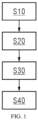
- FIG. 1 is a flowchart of an exemplary implementation of a correction method for a scatter signal caused by a wedge filter.
- the correction method for a scatter signal caused by a wedge filter includes following steps.
- S 10 Perform an air scan by using CT equipment, and calculate a relative intensity of a scatter signal caused by a wedge filter in the air scan according to an air scan result, denoted as an air scan scatter signal relative intensity W air ;
- S20 Perform an object scan on a plurality of experimental objects by using the CT equipment, and calculate theoretical scatter signal intensities W theo of the experimental objects in the object scan according to the air scan scatter signal relative intensity W air , the air scan result, and object scan results of the experimental objects, where the experimental objects may be CT water equivalent phantoms or human bodies.
- S40 Perform an object scan on an actual object by using the CT equipment, calculate a theoretical scatter signal intensity W theo of the actual object in the object scan according to the air scan scatter signal relative intensity W air , the air scan result, and an object scan result of the actual object, calculate a scatter signal intensity estimation W act of the actual object in the object scan according to the fitting formula and the theoretical scatter signal intensity W theo of the actual object in the object scan, and correct the scan results according to a difference between the scatter signal intensity estimation W act of the actual object in the object scan and the theoretical scatter signal intensity W theo of the actual object in the object scan.
- FIG. 2 is another flowchart of an exemplary implementation of a correction method for a scatter signal caused by a wedge filter.
- the correction method for a scatter signal caused by a wedge filter includes the following steps.
- S11 Perform a CT air scan by using a narrow collimator and a wide collimator respectively in a case that the wedge filter is used, to obtain a narrow collimated scatter signal intensity I n_air in the air scan and a wide collimated air scatter signal intensity I b_air in the air scan respectively.
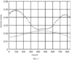
- FIG. 3 shows a difference signal of air scattering obtained in step S11 and step S12, where a solid line represents a case of performing a CT air scan by using a narrow collimator and a wide collimator respectively in a case that a wedge filter is used, and a dotted line represents a case of performing a CT air scan by using the narrow collimator and the wide collimator respectively in a case that the wedge filter is not used.
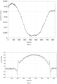
- FIG. 4 shows an air scan scatter signal relative intensity W air obtained by subtracting curves in FIG. 3 .
- S21 Perform a CT object scan on the experimental objects by using the narrow collimator and the wide collimator respectively in a case that the wedge filter is used, to obtain narrow collimated scatter signal intensities I n_obj of the experimental objects in the object scan and wide collimated scatter signal intensities I b_obj in the object scan.
- W act p ⁇ W theo * G Formula (4), where P is a scaling factor, and G is a Gaussian convolution kernel.
- S41 Perform a CT object scan on the actual object by using the wide collimator in a case that the wedge filter is used, to obtain a wide collimated scatter signal intensity I b_obj of the actual object in the object scan.
- S42 Calculate the theoretical scatter signal intensity W theo of the actual object in the object scan by Formula (2) according to the wide collimated scatter signal intensity I b_obj of the actual object in the object scan.
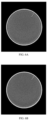
- FIG. 6A shows a reconstructed image of a CT water equivalent phantom with a diameter of 30 cm without being corrected by a method of the present invention.
- FIG. 6B shows a reconstructed image of a CT water equivalent phantom with a diameter of 30 cm corrected by a method of the present invention. It can be seen that an area indicated by an arrow shows that the reconstructed image of the CT water equivalent phantom with a diameter of 30 cm without being corrected by the method of the present invention has darker shade, while the reconstructed image of the CT water equivalent phantom with a diameter of 30 cm corrected by the method of the present invention has lighter shade.
- the methods in the foregoing embodiments may be implemented by means of software and a necessary general hardware platform, and certainly, may be implemented by hardware, but in many cases, the former manner is a better implementation.
- the technical solutions of the present invention or the part that makes contributions to the prior art may be substantially embodied in the form of a software product.
- the computer software product is stored in a storage medium (such as, a ROM/RAM, a magnetic disk, and an optical disc), and contains several instructions to enable a terminal device (which may be a mobile phone, a computer, a server, an air conditioner or a network device) to perform the method according to the embodiments of the present invention.
Landscapes
- Health & Medical Sciences (AREA)
- Life Sciences & Earth Sciences (AREA)
- Engineering & Computer Science (AREA)
- Medical Informatics (AREA)
- Pathology (AREA)
- General Health & Medical Sciences (AREA)
- Physics & Mathematics (AREA)
- Radiology & Medical Imaging (AREA)
- Nuclear Medicine, Radiotherapy & Molecular Imaging (AREA)
- Heart & Thoracic Surgery (AREA)
- Surgery (AREA)
- Veterinary Medicine (AREA)
- Public Health (AREA)
- Animal Behavior & Ethology (AREA)
- Molecular Biology (AREA)
- Biophysics (AREA)
- High Energy & Nuclear Physics (AREA)
- Biomedical Technology (AREA)
- Optics & Photonics (AREA)
- Theoretical Computer Science (AREA)
- Pulmonology (AREA)
- Chemical & Material Sciences (AREA)
- Biochemistry (AREA)
- Immunology (AREA)
- General Physics & Mathematics (AREA)
- Analytical Chemistry (AREA)
- Computer Vision & Pattern Recognition (AREA)
- Apparatus For Radiation Diagnosis (AREA)
Description
- The present invention relates to a correction method, and in particular, to a method for correcting a scatter signal caused by a wedge filter in CT equipment.
- A wedge filter is an exceedingly common assembly in a CT system. The wedge filter may form a more even dose distribution in a patient. Because the wedge filter is a relatively strong attenuation object, the wedge filter generates scatter signals outside a scanned object. Although an air calibration can remove partial scatter signals caused by the wedge filter, some scatter signals still remain in the scanned object.
-
US 2013/058450 A1 relates to a CT system that includes a rotatable gantry having an opening to receive an object to be scanned, an x-ray source configured to project an x-ray beam toward the object having a primary intensity, a detector configured to detect high frequency electromagnetic energy passing through the object and output imaging data, and a data acquisition system (DAS) connected to the detector and configured to receive the imaging data. The system also includes a computer programmed to obtain image projection data of the object from the DAS, correct the projection data using a scatter function that is based at least on a known characteristic of the x-ray beam, and generate images using the corrected projection data. -
CN 111 096 761 A relates to a method and device for correcting scattering of a wedge filter and relative computed tomography equipment. The method for correcting scattering of the wedge filter comprises the following steps: calculating output deltaAirScan, received in an air scan situation, of scattering delta0 of the wedge filter; calculating output deltaObjectScan, received when an object is scanned, of scattering delta0 of the wedge filter; and correcting original data r of the object according to deltaAirScan and deltaObjectScan. The method and device for correcting scattering of the wedge filter and the relative computed tomography equipment significantly improve the quality of images of edges of the scanned object or a scanned patient, and can be applied to processes of system calibration, data pre-processing and image reconstruction conveniently. In dual-energy scanning, the method and device for correcting scattering of the wedge filter and the relative computed tomography equipment have particularly obvious effects. - Zhang Guoqing et al.: "Biomedical Physics & Engineering Express Correction of Bowtie filter induced scatter signals based on air scan data and object scan data", Biomed. Phys. Eng. Express, 2022 discloses that in a cone beam CT system, a bowtie filter brings in additional scatter signals with respect to object induced scatter signals, which can degrade image quality and sometimes result in artifacts. The image quality of CT scans may be improved by analyzing the contribution of bowtie filter induced scatter signals and removing them from projection data.
- At present, the scatter signals caused by the wedge filter may be removed through an anti-scatter grid or a computing model-based correction algorithm, which have strong scene dependence and need to be calibrated for each scene.
- An objective of the present invention is to provide a correction method for a scatter signal caused by a wedge filter, which can correct a scatter signal caused by a wedge filter more accurately.
- The present invention further provides a storage medium, storing a correction program for a scatter signal caused by a wedge filter, where when the correction program is executed by a processor, the steps of the correction method for a scatter signal caused by a wedge filter are processed.
- The present invention provides a correction method for a scatter signal caused by a wedge filter, including: S10: performing an air scan by using CT equipment, and calculating a relative intensity of a scatter signal caused by a wedge filter in the air scan according to an air scan result, denoted as an air scan scatter signal relative intensity Wair; S20: performing an object scan on a plurality of experimental objects by using the CT equipment, and calculating theoretical scatter signal intensities Wtheo of the experimental objects in the object scan according to the air scan scatter signal relative intensity Wair, the air scan result, and object scan results of the experimental objects; S30: fitting the theoretical scatter signal intensities Wtheo of the experimental objects in the object scan and measured scatter signal intensities Wmeas of the experimental objects in the object scan according to the object scan results of the experimental objects, to obtain a fitting formula for calculating a scatter signal intensity estimation Wact, and S40: performing an object scan on an actual object by using the CT equipment, calculating a theoretical scatter signal intensity Wtheo of the actual object in the object scan according to the air scan scatter signal relative intensity Wair, the air scan result, and an object scan result of the actual object, calculating a scatter signal intensity estimation Wact of the actual object in the object scan according to the fitting formula and the theoretical scatter signal intensity Wtheo of the actual object in the object scan, and correcting the scan results according to a difference between the scatter signal intensity estimation Wact of the actual object in the object scan and the theoretical scatter signal intensity Wtheo of the actual object in the object scan.
- In the correction method for a scatter signal caused by a wedge filter provided by the present invention, air scan data is used as an input, so that the estimation of a scatter signal caused by a wedge filter is more accurate. In addition, the method requires fewer algorithms, and is also applicable to scans of clinical patients.
- In another exemplary implementation of the correction method for a scatter signal caused by a wedge filter, step S10 includes: S11: performing a CT air scan by using a narrow collimator and a wide collimator respectively in a case that the wedge filter is used, to obtain a narrow collimated scatter signal intensity In_air in the air scan and a wide collimated air scatter signal intensity Ib_air in the air scan respectively; S12: performing a CT air scan by using the narrow collimator and the wide collimator respectively in a case that the wedge filter is not used, to obtain an initial narrow collimated signal intensity In_p_air in the air scan and an initial wide collimated signal intensity Ib-p-air in the air scan respectively; and S13: calculating the air scan scatter signal relative intensity Wair by Formula (1) below:

- The scatter signal in the air scan with the wedge filter is first obtained in S11, and then the scatter signal in the air scan with the wedge filter is removed in S12. The difference between the scatter signals obtained in S11 and S12 is calculated to obtain the relative intensity in S13. It is only in this case that the obtained signal can be considered as the scatter signal of only the wedge filter. The air scan scatter signal relative intensity obtained in S13 excludes the impact of different initial signal intensities caused by both the wide collimator and the narrow collimator.
- In still another exemplary implementation of the correction method for a scatter signal caused by a wedge filter, step S20 includes: S21: performing a CT object scan on the experimental objects by using the narrow collimator and the wide collimator respectively in a case that the wedge filter is used, to obtain narrow collimated scatter signal intensities In_obj of the experimental objects in the object scan and wide collimated scatter signal intensities Ib_obj in the object scan, and S22: calculating the theoretical scatter signal intensities Wtheo of the experimental objects in the object scan by Formula (2) below: Wtheo = Wair * Ip_obj/Ip_air Formula (2). After air correction in
step 10, the remaining amount of the scatter signals after passing through the experimental objects is calculated instep 20. Because the scattering caused by the experimental objects is not considered, the following steps S30 and S40 are performed. - In still another exemplary implementation of the correction method for a scatter signal caused by a wedge filter, step S30 includes: S31: calculating the measured scatter signal intensities Wmeas of the experimental objects in the object scan by Formula (3) below: Wmeas = I3_obj/I3_air - In-obj/In-air, Formula (3); and S32: fitting Formula (4) below according to the measured scatter signal intensities Wmeas of the experimental objects in the object scan and the theoretical scatter signal intensities Wtheo of the experimental objects in the object scan, where the measured scatter signal intensities Wmeas of the experimental objects in the object scan are used as fit target values of scatter signal intensity estimations Wact in the object scan, Wact = p · Wtheo * G Formula (4), where P is a scaling factor, and G is a Gaussian convolution kernel.
- In still another exemplary implementation of the correction method for a scatter signal caused by a wedge filter, step S40 includes: S41: performing a CT object scan on the actual object by using the wide collimator in a case that the wedge filter is used, to obtain a wide collimated scatter signal intensity Ib_obj of the actual object in the object scan, S42: calculating the theoretical scatter signal intensity Wtheo of the actual object in the object scan by Formula (2) according to the wide collimated scatter signal intensity Ib_obj of the actual object in the object scan, S43: calculating the scatter signal intensity estimation Wact of the actual object in the object scan by the fitting formula, and S44: correcting the scan results according to the difference between the scatter signal intensity estimation Wact of the actual object in the object scan and the theoretical scatter signal intensity Wtheo of the actual object in the object scan.
- The narrow collimator and the wide collimator used in the present invention are both commonly used apparatuses in the CT equipment. The narrow collimator refers to a collimator with an aperture of 0.5 mm or less, and the wide collimator refers to a collimator with an aperture larger than that of the narrow collimator.
- In still another exemplary implementation of the correction method for a scatter signal caused by a wedge filter, the experimental objects are CT water equivalent phantoms.
- The present invention further provides a storage medium, storing a correction program for a scatter signal caused by a wedge filter, where when the correction program is executed by a processor, the step of the foregoing correction method are processed.
- The accompanying drawings below are only intended to provide exemplary descriptions and explanations for the present invention, but are not intended to limit the scope of the present invention.
-
FIG. 1 is a flowchart of an exemplary implementation of a correction method for a scatter signal caused by a wedge filter; -
FIG. 2 is another flowchart of an exemplary implementation of a correction method for a scatter signal caused by a wedge filter; -
FIG. 3 shows a difference signal of an air scan obtained in step S11 and step S12, where a solid line represents a case of performing a CT air scan by using a narrow collimator and a wide collimator respectively in a case that a wedge filter is used, and a dotted line represents a case of performing a CT air scan by using the narrow collimator and the wide collimator respectively in a case that the wedge filter is not used; -
FIG. 4 shows an air scan scatter signal relative intensity Wair obtained in step S13 in an exemplary implementation of a correction method for a scatter signal caused by a wedge filter; -
FIG. 5 shows a fitting process of S32 in an exemplary implementation of a correction method for a scatter signal caused by a wedge filter, where a dotted line shows measured scatter signal intensities Wmeas of experimental objects in an object scan, and a solid line shows scatter signal intensity estimations Wact of the experimental objects in the object scan; -
FIG. 6A shows a reconstructed image of a CT water equivalent phantom with a diameter of 30 cm without being corrected by a method of the present invention; and -
FIG. 6B shows a reconstructed image of a CT water equivalent phantom with a diameter of 30 cm corrected by a method of the present invention. - To have a clearer understanding of the technical features, the objectives, and the effects of the present invention, specific implementations of the present invention are now illustrated with reference to the accompanying drawings. In the accompanying drawings, the same reference numerals represent components with the same structures or similar structures but the same functions.
- In this specification, "exemplary" indicates "serving as an example, a case, or description", and any illustration or implementation described as "schematic" in this specification should not be interpreted as a more preferred or more advantageous technical solution.
- For brevity of the accompanying drawings, only parts related to the present invention are schematically shown in the accompanying drawings, and do not represent actual structures as products.
-
FIG. 1 is a flowchart of an exemplary implementation of a correction method for a scatter signal caused by a wedge filter. Referring toFIG. 1 , the correction method for a scatter signal caused by a wedge filter includes following steps. - S 10: Perform an air scan by using CT equipment, and calculate a relative intensity of a scatter signal caused by a wedge filter in the air scan according to an air scan result, denoted as an air scan scatter signal relative intensity Wair;
- S20: Perform an object scan on a plurality of experimental objects by using the CT equipment, and calculate theoretical scatter signal intensities Wtheo of the experimental objects in the object scan according to the air scan scatter signal relative intensity Wair, the air scan result, and object scan results of the experimental objects, where the experimental objects may be CT water equivalent phantoms or human bodies.
- S30: Fit the theoretical scatter signal intensities Wtheo of the experimental objects in the object scan and measured scatter signal intensities Wmeas of the experimental objects in the object scan according to the object scan results of the experimental objects, to obtain a fitting formula for calculating a scatter signal intensity estimation Wact, and
- S40: Perform an object scan on an actual object by using the CT equipment, calculate a theoretical scatter signal intensity Wtheo of the actual object in the object scan according to the air scan scatter signal relative intensity Wair, the air scan result, and an object scan result of the actual object, calculate a scatter signal intensity estimation Wact of the actual object in the object scan according to the fitting formula and the theoretical scatter signal intensity Wtheo of the actual object in the object scan, and correct the scan results according to a difference between the scatter signal intensity estimation Wact of the actual object in the object scan and the theoretical scatter signal intensity Wtheo of the actual object in the object scan.
-
FIG. 2 is another flowchart of an exemplary implementation of a correction method for a scatter signal caused by a wedge filter. Referring toFIG. 2 , the correction method for a scatter signal caused by a wedge filter includes the following steps. - S11: Perform a CT air scan by using a narrow collimator and a wide collimator respectively in a case that the wedge filter is used, to obtain a narrow collimated scatter signal intensity In_air in the air scan and a wide collimated air scatter signal intensity Ib_air in the air scan respectively.
- S12: Perform a CT air scan by using the narrow collimator and the wide collimator respectively in a case that the wedge filter is not used, to obtain an initial narrow collimated signal intensity In_p_air in the air scan and an initial wide collimated signal intensity Ib_p_air in the air scan respectively.
FIG. 3 shows a difference signal of air scattering obtained in step S11 and step S12, where a solid line represents a case of performing a CT air scan by using a narrow collimator and a wide collimator respectively in a case that a wedge filter is used, and a dotted line represents a case of performing a CT air scan by using the narrow collimator and the wide collimator respectively in a case that the wedge filter is not used. - S13: Calculate the air scan scatter signal relative intensity Wair by Formula (1) below:

-
FIG. 4 shows an air scan scatter signal relative intensity Wair obtained by subtracting curves inFIG. 3 . - S21: Perform a CT object scan on the experimental objects by using the narrow collimator and the wide collimator respectively in a case that the wedge filter is used, to obtain narrow collimated scatter signal intensities In_obj of the experimental objects in the object scan and wide collimated scatter signal intensities Ib_obj in the object scan.
- S22: Calculate the theoretical scatter signal intensities Wtheo of the experimental objects in the object scan by Formula (2) below:

- S31: Calculate the measured scatter signal intensities Wmeas of the experimental objects in the object scan by Formula (3) below:

- S32: Fit Formula (4) below according to the measured scatter signal intensities Wmeas of the experimental objects in the object scan and the theoretical scatter signal intensities Wtheo of the experimental objects in the object scan, where the measured scatter signal intensities Wmeas of the experimental objects in the object scan are used as fit target values of scatter signal intensity estimations Wact in the object scan,
- Wact = p · Wtheo * G Formula (4), where P is a scaling factor, and G is a Gaussian convolution kernel.
- S41: Perform a CT object scan on the actual object by using the wide collimator in a case that the wedge filter is used, to obtain a wide collimated scatter signal intensity Ib_obj of the actual object in the object scan.
- S42: Calculate the theoretical scatter signal intensity Wtheo of the actual object in the object scan by Formula (2) according to the wide collimated scatter signal intensity Ib_obj of the actual object in the object scan.
- S43: Calculate the scatter signal intensity estimation Wact of the actual object in the object scan by the fitting formula.
- S44: Correct the scan results according to the difference between the scatter signal intensity estimation Wact of the actual object in the object scan and the theoretical scatter signal intensity Wtheo of the actual object in the object scan.
-
FIG. 6A shows a reconstructed image of a CT water equivalent phantom with a diameter of 30 cm without being corrected by a method of the present invention.FIG. 6B shows a reconstructed image of a CT water equivalent phantom with a diameter of 30 cm corrected by a method of the present invention. It can be seen that an area indicated by an arrow shows that the reconstructed image of the CT water equivalent phantom with a diameter of 30 cm without being corrected by the method of the present invention has darker shade, while the reconstructed image of the CT water equivalent phantom with a diameter of 30 cm corrected by the method of the present invention has lighter shade. - Through the descriptions of the foregoing implementations, a person skilled in the art may clearly understand that the methods in the foregoing embodiments may be implemented by means of software and a necessary general hardware platform, and certainly, may be implemented by hardware, but in many cases, the former manner is a better implementation. Based on such an understanding, the technical solutions of the present invention or the part that makes contributions to the prior art may be substantially embodied in the form of a software product. The computer software product is stored in a storage medium (such as, a ROM/RAM, a magnetic disk, and an optical disc), and contains several instructions to enable a terminal device (which may be a mobile phone, a computer, a server, an air conditioner or a network device) to perform the method according to the embodiments of the present invention.
- A series of detailed descriptions listed above are only specific descriptions of the feasible embodiments of the present invention, which are not intended to limit the protection scope of the present invention.
Claims (7)
- A computer-implemented correction method for a scatter signal caused by a wedge filter, comprising:S10: performing (S10) an air scan by using CT equipment, and calculating a relative intensity of a scatter signal caused by a wedge filter in the air scan according to an air scan result, denoted as an air scan scatter signal relative intensity Wair,S20: performing (S20) an object scan on a plurality of experimental objects by using the CT equipment, and calculating theoretical scatter signal intensities Wtheo of the experimental objects in the object scan according to the air scan scatter signal relative intensity Wair, the air scan result, and object scan results of the experimental objects,S30: fitting (S30) the theoretical scatter signal intensities Wtheo of the experimental objects in the object scan and measured scatter signal intensities Wmeas of the experimental objects in the object scan according to the object scan results of the experimental objects, to obtain a fitting formula for calculating a scatter signal intensity estimation Wact, andS40: performing (S40) an object scan on an actual object by using the CT equipment, calculating a theoretical scatter signal intensity Wtheo of the actual object in the object scan according to the air scan scatter signal relative intensity Wair, the air scan result, and an object scan result of the actual object, calculating a scatter signal intensity estimation Wact of the actual object in the object scan according to the fitting formula and the theoretical scatter signal intensity Wtheo of the actual object in the object scan, and correcting the scan results according to a difference between the scatter signal intensity estimation Wact of the actual object in the object scan and the theoretical scatter signal intensity Wtheo of the actual object in the object scan.
- The correction method for a scatter signal caused by a wedge filter according to claim 1, wherein step S10 comprises:S11: performing (S11) a CT air scan by using a narrow collimator and a wide collimator respectively in a case that the wedge filter is used, to obtain a narrow collimated scatter signal intensity In_air in the air scan and a wide collimated air scatter signal intensity Ib_air in the air scan respectively,S12: performing (S12) a CT air scan by using the narrow collimator and the wide collimator respectively in a case that the wedge filter is not used, to obtain an initial narrow collimated signal intensity In_p_air in the air scan and an initial wide collimated signal intensity Ib_p_air in the air scan respectively, andS13: calculating (S13) the air scan scatter signal relative intensity Wair by Formula (1) below:

- The correction method for a scatter signal caused by a wedge filter according to claim 2, wherein step S20 comprises:S21: performing (S21) a CT object scan on the experimental objects by using the narrow collimator and the wide collimator respectively in a case that the wedge filter is used, to obtain narrow collimated scatter signal intensities In_obj of the experimental objects in the object scan and wide collimated scatter signal intensities Ib_obj in the object scan, andS22: calculating (S22) the theoretical scatter signal intensities Wtheo of the experimental objects in the object scan by Formula (2) below:

- The correction method for a scatter signal caused by a wedge filter according to claim 3, wherein step S30 comprises:S31: calculating (S31) the measured scatter signal intensities Wmeas of the experimental objects in the object scan by Formula (3) below:
 S32: fitting (S32) Formula (4) below according to the measured scatter signal intensities Wmeas of the experimental objects in the object scan and the theoretical scatter signal intensities Wtheo of the experimental objects in the object scan, wherein the measured scatter signal intensities Wmeas of the experimental objects in the object scan are used as fit target values of scatter signal intensity estimations Wact in the object scan,
 P is a scaling factor, and G is a Gaussian convolution kernel.
 - The correction method for a scatter signal caused by a wedge filter according to claim 4, wherein step S40 comprises:S41: performing (S41) a CT object scan on the actual object by using the wide collimator in a case that the wedge filter is used, to obtain a wide collimated scatter signal intensity Ib_obj of the actual object in the object scan,S42: calculating (S42) the theoretical scatter signal intensity Wtheo of the actual object in the object scan by Formula (2) according to the wide collimated scatter signal intensity Ib_obj of the actual object in the object scan,S43: calculating (S43) the scatter signal intensity estimation (Wact) of the actual object in the object scan by the fitting formula, andS44: correcting (S44) the scan results according to the difference between the scatter signal intensity estimation Wact of the actual object in the object scan and the theoretical scatter signal intensity Wtheo of the actual object in the object scan.
- The correction method for a scatter signal caused by a wedge filter according to claim 1, wherein the experimental objects are CT water equivalent phantoms.
- A storage medium, storing a correction program for a scatter signal caused by a wedge filter, wherein when the correction program is executed by a processor, the steps of the correction method according to any one of claims 1 to 6 are processed.
Applications Claiming Priority (2)
| Application Number | Priority Date | Filing Date | Title |
|---|---|---|---|
| CN202111162044.0A CN115869000A (en) | 2021-09-30 | 2021-09-30 | Correction method and storage medium for scattered signal caused by wedge filter |
| PCT/CN2022/114507 WO2023051107A1 (en) | 2021-09-30 | 2022-08-24 | Correction method for scatter signal caused by wedge filter and storage medium |
Publications (3)
| Publication Number | Publication Date |
|---|---|
| EP4391915A1 EP4391915A1 (en) | 2024-07-03 |
| EP4391915C0 EP4391915C0 (en) | 2025-04-23 |
| EP4391915B1 true EP4391915B1 (en) | 2025-04-23 |
Family
ID=83228703
Family Applications (1)
| Application Number | Title | Priority Date | Filing Date |
|---|---|---|---|
| EP22765401.9A Active EP4391915B1 (en) | 2021-09-30 | 2022-08-24 | Correction method for scatter signal caused by wedge filter and storage medium |
Country Status (4)
| Country | Link |
|---|---|
| US (1) | US12625092B2 (en) |
| EP (1) | EP4391915B1 (en) |
| CN (1) | CN115869000A (en) |
| WO (1) | WO2023051107A1 (en) |
Family Cites Families (9)
| Publication number | Priority date | Publication date | Assignee | Title |
|---|---|---|---|---|
| JP3583554B2 (en) * | 1996-07-23 | 2004-11-04 | 株式会社日立メディコ | Cone beam X-ray tomography system |
| DE102005048397A1 (en) | 2005-10-10 | 2007-04-12 | Siemens Ag | Method for radiation correction of a CT system |
| US8611627B2 (en) * | 2009-12-23 | 2013-12-17 | General Electric Company | CT spectral calibration |
| US9320477B2 (en) * | 2011-09-01 | 2016-04-26 | General Electric Company | Method and apparatus for adaptive scatter correction |
| DE102011089643A1 (en) * | 2011-12-22 | 2013-06-27 | Siemens Aktiengesellschaft | Method for correcting scattered radiation for computed tomography X-ray imaging, involves correcting scattered radiation based on estimated result of radiation distribution such that correction variable depends on path length in filter |
| DE102015222837B3 (en) * | 2015-11-19 | 2017-01-05 | Friedrich-Alexander-Universität Erlangen-Nürnberg | Method for reconstructing a three-dimensional image data set from two-dimensional projection images, X-ray device and computer program |
| US10593070B2 (en) * | 2017-12-22 | 2020-03-17 | Canon Medical Systems Corporation | Model-based scatter correction for computed tomography |
| CN108606805B (en) * | 2018-03-15 | 2022-02-11 | 东软医疗系统股份有限公司 | A kind of scattering correction method, device and equipment |
| CN111096761B (en) * | 2018-10-29 | 2024-03-08 | 上海西门子医疗器械有限公司 | Method, device and related equipment for correcting scattering of wedge-shaped filter |
-
2021
- 2021-09-30 CN CN202111162044.0A patent/CN115869000A/en active Pending
-
2022
- 2022-08-24 EP EP22765401.9A patent/EP4391915B1/en active Active
- 2022-08-24 US US18/696,435 patent/US12625092B2/en active Active
- 2022-08-24 WO PCT/CN2022/114507 patent/WO2023051107A1/en not_active Ceased
Also Published As
| Publication number | Publication date |
|---|---|
| EP4391915C0 (en) | 2025-04-23 |
| WO2023051107A1 (en) | 2023-04-06 |
| EP4391915A1 (en) | 2024-07-03 |
| US12625092B2 (en) | 2026-05-12 |
| CN115869000A (en) | 2023-03-31 |
| US20240385128A1 (en) | 2024-11-21 |
Similar Documents
| Publication | Publication Date | Title |
|---|---|---|
| US10292672B2 (en) | Radiographic image processing device, method, and recording medium | |
| US10235766B2 (en) | Radiographic image analysis device and method, and storage medium having stored therein program | |
| US10395396B2 (en) | X-ray CT apparatus, reconfiguration arithmetic apparatus, and X-ray CT image generation method | |
| Prell et al. | Comparison of ring artifact correction methods for flat-detector CT | |
| US8818065B2 (en) | Methods and apparatus for scatter correction for CBCT system and cone-beam image reconstruction | |
| RU2565507C2 (en) | System and method for improving image quality | |
| US10621756B2 (en) | Apparatus and method for correcting bias in low-count computed tomography projection data | |
| Li et al. | Scatter kernel estimation with an edge-spread function method for cone-beam computed tomography imaging | |
| US8837666B2 (en) | X-ray CT apparatus | |
| EP2581876A1 (en) | Method for correcting digital images | |
| US10194879B2 (en) | Image processing method, image processing apparatus and radiation tomographic imaging apparatus, and program | |
| EP2533197A2 (en) | Parameter-less noise reduction filter | |
| US10605933B2 (en) | X-ray spectral calibration technique for cone-beam CT | |
| EP2567659A1 (en) | Calibration free dual energy radiography method. | |
| Kawamura et al. | Improvement in image quality and workflow of x-ray examinations using a new image processing method,“Virtual Grid Technology” | |
| US11369331B2 (en) | Method for artifact reduction in a medical image data set, X-ray device, computer program and electronically readable data carrier | |
| US10098603B2 (en) | Method for estimation and correction of grid pattern due to scatter | |
| JP2017093879A (en) | X-ray measurement system and X-ray detection data processing method | |
| JP4584550B2 (en) | X-ray measuring device | |
| US20200236303A1 (en) | Radiation imaging system, image processing method, and non-transitory computer-readable storage medium | |
| US12625092B2 (en) | Correction method for scatter signal caused by wedge filter | |
| KR101821046B1 (en) | Method and device for estimating metal artifacts of ct image and method for determining metal artifacts calibration | |
| US10152805B2 (en) | Image processing method, image processing apparatus and radiation tomographic imaging apparatus, and program | |
| JP2002153454A (en) | X-ray ct device | |
| CN112566554B (en) | Bias correction caused by detector shearing in imaging systems |
Legal Events
| Date | Code | Title | Description |
|---|---|---|---|
| STAA | Information on the status of an ep patent application or granted ep patent |
Free format text: STATUS: UNKNOWN |
|
| STAA | Information on the status of an ep patent application or granted ep patent |
Free format text: STATUS: THE INTERNATIONAL PUBLICATION HAS BEEN MADE |
|
| PUAI | Public reference made under article 153(3) epc to a published international application that has entered the european phase |
Free format text: ORIGINAL CODE: 0009012 |
|
| STAA | Information on the status of an ep patent application or granted ep patent |
Free format text: STATUS: REQUEST FOR EXAMINATION WAS MADE |
|
| 17P | Request for examination filed |
Effective date: 20240326 |
|
| AK | Designated contracting states |
Kind code of ref document: A1 Designated state(s): AL AT BE BG CH CY CZ DE DK EE ES FI FR GB GR HR HU IE IS IT LI LT LU LV MC MK MT NL NO PL PT RO RS SE SI SK SM TR |
|
| REG | Reference to a national code |
Ref country code: DE Ipc: A61B0006000000 Ref country code: DE Ref legal event code: R079 Ref document number: 602022013671 Country of ref document: DE Free format text: PREVIOUS MAIN CLASS: A61B0006030000 Ipc: A61B0006000000 |
|
| DAV | Request for validation of the european patent (deleted) | ||
| DAX | Request for extension of the european patent (deleted) | ||
| GRAP | Despatch of communication of intention to grant a patent |
Free format text: ORIGINAL CODE: EPIDOSNIGR1 |
|
| STAA | Information on the status of an ep patent application or granted ep patent |
Free format text: STATUS: GRANT OF PATENT IS INTENDED |
|
| RIC1 | Information provided on ipc code assigned before grant |
Ipc: A61B 6/42 20240101ALI20241212BHEP Ipc: A61B 6/40 20240101ALI20241212BHEP Ipc: A61B 6/06 20060101ALI20241212BHEP Ipc: A61B 6/03 20060101ALI20241212BHEP Ipc: A61B 6/00 20240101AFI20241212BHEP |
|
| INTG | Intention to grant announced |
Effective date: 20250115 |
|
| GRAS | Grant fee paid |
Free format text: ORIGINAL CODE: EPIDOSNIGR3 |
|
| GRAA | (expected) grant |
Free format text: ORIGINAL CODE: 0009210 |
|
| STAA | Information on the status of an ep patent application or granted ep patent |
Free format text: STATUS: THE PATENT HAS BEEN GRANTED |
|
| AK | Designated contracting states |
Kind code of ref document: B1 Designated state(s): AL AT BE BG CH CY CZ DE DK EE ES FI FR GB GR HR HU IE IS IT LI LT LU LV MC MK MT NL NO PL PT RO RS SE SI SK SM TR |
|
| RAP3 | Party data changed (applicant data changed or rights of an application transferred) |
Owner name: SIEMENS SHANGHAI MEDICAL EQUIPMENT LTD. |
|
| REG | Reference to a national code |
Ref country code: GB Ref legal event code: FG4D |
|
| REG | Reference to a national code |
Ref country code: CH Ref legal event code: EP |
|
| REG | Reference to a national code |
Ref country code: IE Ref legal event code: FG4D |
|
| U01 | Request for unitary effect filed |
Effective date: 20250423 |
|
| U07 | Unitary effect registered |
Designated state(s): AT BE BG DE DK EE FI FR IT LT LU LV MT NL PT RO SE SI Effective date: 20250428 |
|
| U20 | Renewal fee for the european patent with unitary effect paid |
Year of fee payment: 4 Effective date: 20250820 |
|
| PG25 | Lapsed in a contracting state [announced via postgrant information from national office to epo] |
Ref country code: ES Free format text: LAPSE BECAUSE OF FAILURE TO SUBMIT A TRANSLATION OF THE DESCRIPTION OR TO PAY THE FEE WITHIN THE PRESCRIBED TIME-LIMIT Effective date: 20250423 |
|
| PG25 | Lapsed in a contracting state [announced via postgrant information from national office to epo] |
Ref country code: NO Free format text: LAPSE BECAUSE OF FAILURE TO SUBMIT A TRANSLATION OF THE DESCRIPTION OR TO PAY THE FEE WITHIN THE PRESCRIBED TIME-LIMIT Effective date: 20250723 Ref country code: GR Free format text: LAPSE BECAUSE OF FAILURE TO SUBMIT A TRANSLATION OF THE DESCRIPTION OR TO PAY THE FEE WITHIN THE PRESCRIBED TIME-LIMIT Effective date: 20250724 |
|
| PG25 | Lapsed in a contracting state [announced via postgrant information from national office to epo] |
Ref country code: PL Free format text: LAPSE BECAUSE OF FAILURE TO SUBMIT A TRANSLATION OF THE DESCRIPTION OR TO PAY THE FEE WITHIN THE PRESCRIBED TIME-LIMIT Effective date: 20250423 |
|
| PG25 | Lapsed in a contracting state [announced via postgrant information from national office to epo] |
Ref country code: HR Free format text: LAPSE BECAUSE OF FAILURE TO SUBMIT A TRANSLATION OF THE DESCRIPTION OR TO PAY THE FEE WITHIN THE PRESCRIBED TIME-LIMIT Effective date: 20250423 |
|
| PG25 | Lapsed in a contracting state [announced via postgrant information from national office to epo] |
Ref country code: RS Free format text: LAPSE BECAUSE OF FAILURE TO SUBMIT A TRANSLATION OF THE DESCRIPTION OR TO PAY THE FEE WITHIN THE PRESCRIBED TIME-LIMIT Effective date: 20250723 |
|
| PG25 | Lapsed in a contracting state [announced via postgrant information from national office to epo] |
Ref country code: IS Free format text: LAPSE BECAUSE OF FAILURE TO SUBMIT A TRANSLATION OF THE DESCRIPTION OR TO PAY THE FEE WITHIN THE PRESCRIBED TIME-LIMIT Effective date: 20250823 |
|
| PG25 | Lapsed in a contracting state [announced via postgrant information from national office to epo] |
Ref country code: SM Free format text: LAPSE BECAUSE OF FAILURE TO SUBMIT A TRANSLATION OF THE DESCRIPTION OR TO PAY THE FEE WITHIN THE PRESCRIBED TIME-LIMIT Effective date: 20250423 |
|
| PG25 | Lapsed in a contracting state [announced via postgrant information from national office to epo] |
Ref country code: CZ Free format text: LAPSE BECAUSE OF FAILURE TO SUBMIT A TRANSLATION OF THE DESCRIPTION OR TO PAY THE FEE WITHIN THE PRESCRIBED TIME-LIMIT Effective date: 20250423 |
|
| PG25 | Lapsed in a contracting state [announced via postgrant information from national office to epo] |
Ref country code: SK Free format text: LAPSE BECAUSE OF FAILURE TO SUBMIT A TRANSLATION OF THE DESCRIPTION OR TO PAY THE FEE WITHIN THE PRESCRIBED TIME-LIMIT Effective date: 20250423 |
|
| PLBE | No opposition filed within time limit |
Free format text: ORIGINAL CODE: 0009261 |
|
| STAA | Information on the status of an ep patent application or granted ep patent |
Free format text: STATUS: NO OPPOSITION FILED WITHIN TIME LIMIT |
|
| REG | Reference to a national code |
Ref country code: CH Ref legal event code: L10 Free format text: ST27 STATUS EVENT CODE: U-0-0-L10-L00 (AS PROVIDED BY THE NATIONAL OFFICE) Effective date: 20260304 |
|
| REG | Reference to a national code |
Ref country code: CH Ref legal event code: H13 Free format text: ST27 STATUS EVENT CODE: U-0-0-H10-H13 (AS PROVIDED BY THE NATIONAL OFFICE) Effective date: 20260324 |
|
| PG25 | Lapsed in a contracting state [announced via postgrant information from national office to epo] |
Ref country code: MC Free format text: LAPSE BECAUSE OF FAILURE TO SUBMIT A TRANSLATION OF THE DESCRIPTION OR TO PAY THE FEE WITHIN THE PRESCRIBED TIME-LIMIT Effective date: 20250423 |
|
| 26N | No opposition filed |
Effective date: 20260126 |
|
| PG25 | Lapsed in a contracting state [announced via postgrant information from national office to epo] |
Ref country code: CH Free format text: LAPSE BECAUSE OF NON-PAYMENT OF DUE FEES Effective date: 20250831 |