EP4391754A1 - Oil-cooled rectifier diode assembly - Google Patents
Oil-cooled rectifier diode assembly Download PDFInfo
- Publication number
- EP4391754A1 EP4391754A1 EP23211325.8A EP23211325A EP4391754A1 EP 4391754 A1 EP4391754 A1 EP 4391754A1 EP 23211325 A EP23211325 A EP 23211325A EP 4391754 A1 EP4391754 A1 EP 4391754A1
- Authority
- EP
- European Patent Office
- Prior art keywords
- bus bars
- cooling
- bus bar
- diode array
- power diode
- Prior art date
- Legal status (The legal status is an assumption and is not a legal conclusion. Google has not performed a legal analysis and makes no representation as to the accuracy of the status listed.)
- Pending
Links
Images




Classifications
-
- H—ELECTRICITY
- H05—ELECTRIC TECHNIQUES NOT OTHERWISE PROVIDED FOR
- H05K—PRINTED CIRCUITS; CASINGS OR CONSTRUCTIONAL DETAILS OF ELECTRIC APPARATUS; MANUFACTURE OF ASSEMBLAGES OF ELECTRICAL COMPONENTS
- H05K7/00—Constructional details common to different types of electric apparatus
- H05K7/20—Modifications to facilitate cooling, ventilating, or heating
- H05K7/2089—Modifications to facilitate cooling, ventilating, or heating for power electronics, e.g. for inverters for controlling motor
- H05K7/20927—Liquid coolant without phase change
-
- H—ELECTRICITY
- H02—GENERATION; CONVERSION OR DISTRIBUTION OF ELECTRIC POWER
- H02M—APPARATUS FOR CONVERSION BETWEEN AC AND AC, BETWEEN AC AND DC, OR BETWEEN DC AND DC, AND FOR USE WITH MAINS OR SIMILAR POWER SUPPLY SYSTEMS; CONVERSION OF DC OR AC INPUT POWER INTO SURGE OUTPUT POWER; CONTROL OR REGULATION THEREOF
- H02M7/00—Conversion of AC power input into DC power output; Conversion of DC power input into AC power output
- H02M7/003—Constructional details, e.g. physical layout, assembly, wiring or busbar connections
-
- H—ELECTRICITY
- H05—ELECTRIC TECHNIQUES NOT OTHERWISE PROVIDED FOR
- H05K—PRINTED CIRCUITS; CASINGS OR CONSTRUCTIONAL DETAILS OF ELECTRIC APPARATUS; MANUFACTURE OF ASSEMBLAGES OF ELECTRICAL COMPONENTS
- H05K7/00—Constructional details common to different types of electric apparatus
- H05K7/14—Mounting supporting structure in casing or on frame or rack
- H05K7/1422—Printed circuit boards receptacles, e.g. stacked structures, electronic circuit modules or box like frames
- H05K7/1427—Housings
- H05K7/1432—Housings specially adapted for power drive units or power converters
- H05K7/14329—Housings specially adapted for power drive units or power converters specially adapted for the configuration of power bus bars
Definitions
- aircraft generator rectifier assemblies include diodes packaged in modules, wherein a die is mounted to a substrate and the substrate is, in-turn, mounted to a cold plate, through which oil circulates.
- fins are added to the cooling path to improve cooling performance, as well as other modifications that often do not substantially improve performance, and which sometimes negatively impact overall weight.
- diode assembly 100 of Figure 1 a flow of oil 190 passes through a channel 131 formed in a cold plate 130, in which fins 133 are provided. Heat is transferred from the diodes 110, through a substrate 120 to the cold plate 130 and ultimately to the fluid 190.
- this relatively inefficient arrangement can result in a very low or even negative thermal margin, when under high power load with a hot cooling oil condition.
- devices, systems and methods are provided that relate to fluid-cooled rectifier diode assemblies with reduced volume and weight, and enhanced cooling characteristics, as compared with the prior art.
- a liquid-cooled rectifier assembly includes a first bus bar having at least one cooling channel formed therein, adapted and configured to carry a cooling fluid therethrough, a second bus bar having at least one cooling channel formed therein, adapted and configured to carry the cooling fluid therethrough, and a first power diode array arranged between and in contact with the first and second bus bars.
- the first and second bus bars can define outer walls of a fluid chamber, cooling fluid entering the chamber and being distributed, at least in-part, through cooling channels formed in the first and second bus bars.
- the first and second bus bars can define outer walls of a fluid chamber, cooling fluid entering the chamber and being distributed, at least in-part, around the outer surface of the first power diode array.
- the first bus bar can have a plurality of cooling channels formed therein.
- the second bus bar can have a plurality of cooling channels formed therein.
- the subject liquid-cooled rectifier assemblies can further include at least one bolt, adapted and configured to compress the first and second bus bars onto the first power diode array, in order to optimize electrical and thermal contact between the first and second bus bars and the first power diode array.
- the subject liquid-cooled rectifier assemblies can further include at least one spring element, adapted and configured to, in combination with the at least one bolt, compress the first and second bus bars onto the first power diode array, in order to optimize electrical and thermal contact between the first and second bus bars and the first power diode array.
- the subject liquid-cooled rectifier assemblies can further include a third bus bar having at least one cooling channel formed therein, adapted and configured to carry the cooling fluid therethrough, and a second power diode array arranged between and in contact with the second and third bus bars.
- the third bus bar can have a plurality of cooling channels formed therein.
- At least one bolt can be provided, adapted and configured to compress the second and third bus bars onto the second power diode array, in order to optimize electrical and thermal contact between the second and third bus bars and the second power diode array.
- At least one spring element can be provided, adapted and configured to, in combination with the at least one bolt, compress the second and third bus bars onto the second power diode array, in order to optimize electrical and thermal contact between the second and third bus bars and the second power diode array.
- the first and third bus bars can define outer walls of a fluid chamber, cooling fluid entering the chamber and being distributed, at least in-part, through cooling channels formed in the first, second and third bus bars.
- the first and third bus bars can be formed from aluminum or an aluminum alloy, and the second bus bar is formed from copper or a copper alloy.
- a method of cooling a rectifier diode assembly includes the steps of providing a first bus bar having at least one cooling channel formed therein, adapted and configured to carry a cooling fluid therethrough, providing a second bus bar having at least one cooling channel formed therein, adapted and configured to carry the cooling fluid therethrough, providing a first power diode array arranged between and in contact with the first and second bus bars, and passing a cooling fluid through the first and second bus bars, thereby cooling the first power diode array.
- the cooling fluid can be oil.
- the oil can be turbine sump oil.
- an oil-cooled rectifier diode assembly 200 is illustrated.
- One or more diodes 230 are arranged between bus bars 210, 220.
- the first bus bar 210 includes fluid channels 215 formed therein, and can optionally include a parting sheet 217 to optimize fluid flow characteristics along the upper surface of the diode 230-- in this case, the anode 233.
- the second bus bar 220 includes fluid channels 225 formed therein, and can also optionally include a parting sheet to close the lower end of fluid channel 225 to optimize fluid flow characteristics.
- the bus bars 210, 220 can be formed by any suitable techniques, including but not limited to casting, extrusion and/or machining.
- bus bars 210, 220 can each be formed of a single piece, or formed by joining multiple pieces together.
- the bus bars 210, 220 can be formed out of any suitable material, which is preferably highly thermally and electrically conductive.
- copper and aluminum are preferred as practical choices, with aluminum advantageously offering weight savings-naturally an important factor in aeronautical applications.
- copper may be preferred over aluminum, as will be described in more detail below.
- An insulating material 240 can be provided to stabilize the diodes 230, which itself can have cooling channels formed therethrough. Alternatively, these areas occupied by the insulating material 240 can be left open to allow free passage of cooling fluid over the exposed surfaces of the diode(s) 230, anode(s) 233 and cathode(s) 235.
- a continuous force is preferably exerted on the diode(s) by the bus bars.
- This force can be applied in any suitable manner, but in accordance with one preferred aspect, the force is achieved by way of a plurality of bolts and resilient biasing members, such as springs, which are illustrated and described herein in connection with other embodiments.
- an isometric view of an oil-cooled rectifier diode assembly 300 is illustrated, having cooling fluid plenums 350, 360 on each end of cooling channels formed in bus bars 210, 220.
- Fluid is provided from a cooling fluid circuit, which can be a cooled engine oil circuit, for example, to a supply plenum 350, from where it flows through channels formed in bus bars 210, 220 to an output plenum 360, from where the fluid returns to the cooling fluid circuit.
- a cooling fluid circuit which can be a cooled engine oil circuit, for example, to a supply plenum 350, from where it flows through channels formed in bus bars 210, 220 to an output plenum 360, from where the fluid returns to the cooling fluid circuit.
- an alternate round cross-sectional geometry of cooling channels is shown.
- Such geometries can be fabricated in a conventional manner, such as by extrusion, and/or machining, or by newer technologies such as additive manufacturing techniques. Such techniques can be applied to all embodiments described herein.
- Figure 4 is a schematic cross-sectional end view of an oil-cooled rectifier diode assembly 400 in accordance with still another aspect of the present invention, including alternate arrangements for cooling channels 415, 425a, 425b in bus bars 410, 420.
- the first bus bar 410 includes fluid channels 415 formed therein. In this embodiment, channels 415 are spaced further apart than in the embodiment of Figure 2 .
- the first bus bar 410 can optionally include a parting sheet 417 to optimize fluid flow characteristics along the upper surface of the diode 230.
- the second bus bar 420 includes fluid channels 425a, 425b formed therein in an alternating manner, as compared with the embodiment of Figure 2 .
- the second bus bar 420 can optionally include a parting sheet 427 to close the upper end of fluid channel 425b to optimize fluid flow characteristics. Additionally, another parting sheet can be applied to the lower end of fluid channels 425a.
- the bus bars 410, 420 can be formed by any suitable techniques, including but not limited to casting, extrusion and/or machining. Further the bus bars 410, 420 can each be formed of a single piece, or formed by joining multiple pieces together. The bus bars 410, 420 can be formed out of any preferably highly thermally and electrically conductive material. Copper and aluminum are preferred as practical choices, but other materials can be used, depending on the desired implementation.
- An insulating material 440 can be provided to stabilize the diodes 230, which itself can have cooling channels formed therethrough. Alternatively, these areas occupied by the insulating material 440 can be left open to allow free passage of cooling fluid over the exposed surfaces of the diode(s) 230, anode(s) 233 and cathode(s) 235.
- the embodiment of Figure 4 further includes additional cooling channels 445 arranged between the insulating material 440 and the second bus bar 420. Such channels 445 can be defined simply by the boundary of the adjacent structures, or can alternatively be housed in a separate conduit.
- Figure 5 is a schematic cross-sectional end view of an oil-cooled rectifier diode assembly 500 in accordance with a further aspect of the present invention, in which a second level of one or more diodes is provided on the lower face of an intermediate bus bar 520, and a third bus bar 570 is also provided.
- the intermediate bus bar 520 can be utilized as the AC bus bar, with outer bus bars being utilized for DC.
- One or more diodes 230 are arranged in a first array between bus bars 410, 520.
- the first bus bar 410 includes fluid channels 415 formed therein.
- the first bus bar 510 can optionally include a parting sheet to optimize fluid flow characteristics along the upper surface of the diode 230.
- the second bus bar 520 includes fluid channels 525a, 525b, 525c formed therein.
- the second bus bar 520 can optionally include a parting sheet to close the upper end of fluid channel 525b and another parting sheet can be applied to the lower end of fluid channels 525c to optimize fluid flow characteristics, if desired.
- array means an arrangement of one or more individual diodes. Such an array can include a single diode, or multiple diodes arranged in any pattern.
- one or more diodes 230 are arranged in a second array between bus bars 520, 570.
- the third bus bar 570 includes fluid channels 515 formed therein.
- the third bus bar 570 can optionally include a parting sheet to optimize fluid flow characteristics along the lower surface of the adjacent diode(s) 230.
- the bus bars 410, 520, 570 can be formed by any suitable techniques, including but not limited to casting, extrusion and/or machining. Further the bus bars 410, 520, 570 can each be formed of a single piece, or formed by joining multiple pieces together. The bus bars 410, 520, 570 can be formed out of any preferably highly thermally and electrically conductive material. Copper and aluminum are preferred as practical choices, but other materials can be used, depending on the desired implementation.
- an insulating material 440 can be provided to stabilize the diodes 230, which itself can have cooling channels formed therethrough. Alternatively, the areas occupied by the insulating material 440 can be left open to allow free passage of cooling fluid over the exposed surfaces of the diode(s) 230, anode(s) 233 and cathode(s) 235.
- the embodiment of Figure 5 further includes additional cooling channels 445 arranged between the insulating material 440 and the second bus bar 420. Such channels 445 can be defined simply by the boundary of the adjacent structures, or can alternatively be housed in a separate conduit.
- Figure 6 is a top view of an oil-cooled rectifier diode assembly 600 in accordance with the present invention, illustrating bus bars 610 having cooling channels, and supply plenum 350 and outlet plenum 360.
- Figure 6 illustrates multiple diodes 230 arranged in a linear array, and accordingly it is to be understood that the foregoing embodiments where only cross-sectional end views are shown can represent assemblies having any number of diodes arranged in line, or otherwise, along the common bus bars.
- this and other embodiments described herein can include diodes arranged laterally from those axially-offset diodes 230 illustrated in Figure 6 . That is, where the embodiment Figure 3 could be described as having a 1x1 array of diodes 230, and the embodiment of Figure 6 could be described as having a 1x6 array of diodes 230, all of the diodes being electrically connected in parallel to adjacent bus bars, alternate arrangements of diode arrays are possible and well within the scope of this application. For example, arrays of 2x6, 3x6, 3x3, 4x4, and so on are all possible, and advantageously can be selected based on power requirements, dimensional limitations and thermal characteristics, as needed.
- Figure 7-13 illustrate various components of an oil-cooled rectifier diode assembly 1200 in accordance with the invention.
- Figure 7 is an isometric view illustrating a middle or intermediate bus bar 720 composed of stacked plates 720a, 720b having cooling channels 525a, 525b, 525c formed therein.
- upper middle bus bar 720a includes, extending off of connectors 723, power connections 727, which connections 727 are configured to receive insulators 729 to allow the connections to pass through adjacent bus bars (particularly first outer bus bar 810) having different polarity, as will be seen in connection with additional drawings described hereinbelow.
- sealing elements in this case, O-rings 728 are provided to seal against the outer portions of the assembly. In this manner, loss of cooling fluid from the internal passageways is reduced, and component cooling is thereby enhanced.
- a two levels of diodes 230 are provided, respectively on the upper and lower faces of the intermediate bus bar 720, although only the upper level is fully visible in Figure 7 .
- the first outer bus bar 810 includes fluid channels 815 formed therein.
- the first outer bus bar 810 can optionally include a parting sheet to optimize fluid flow characteristics along the upper surface of the diode 230.
- the inner bus bar 720 includes fluid channels 525a, 525b, 525c formed therein.
- the inner bus bar 720 can optionally include a parting sheet to close the upper end of fluid channel 525b and another parting sheet can be applied to the lower end of fluid channels 525c to optimize fluid flow characteristics, if desired.
- the third bus bar 570 includes fluid channels 515 formed therein.
- the third bus bar 570 can optionally include a parting sheet to optimize fluid flow characteristics along the lower surface of the adjacent diode(s) 230.
- the bus bars 810, 720, 1070 can be formed by any suitable techniques, including but not limited to casting, extrusion and/or machining. Further the bus bars 810, 720, 1070 can each be formed of a single piece, or formed by joining multiple pieces together. The bus bars 810, 720, 1070 can be formed out of any preferably highly thermally and electrically conductive material. Copper and aluminum are preferred as practical choices, but other materials can be used, depending on the desired implementation.
- an insulating material 740 can be provided to stabilize the diodes 230, which itself can have cooling channels formed therethrough.
- the areas occupied by the insulating material 740 can be left open to allow free passage of cooling fluid over the exposed surfaces of the diode(s) 230, anode(s) 233 and cathode(s) 235.
- the diodes of one array are flipped with respect to the diodes of the opposing array, so that the polarity allows sharing of intermediate bus bar 720, leaving the outer bus bars 810, 1070 with a common opposite polarity.
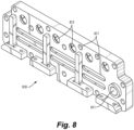
- FIGS 8 and 9 are isometric views of outer and inner surfaces of the first outer bus bar 810, respectively. Illustrated are cooling fluid inlet port 811 and various cutouts 813 to allow for passage of opposing bus bar connections 727 and their insulators 729. Notably, bolt holes 817 are also illustrated. With reference to Figure 9 , an integral cooling fluid channel 815 and surface contours 812 to enhance mechanical, thermal and electrical connection to adjacent diodes are also illustrated.
- FIGS 10 and 11 are isometric views of inner and outer surfaces of the second outer bus bar 1070, respectively. Illustrated are an integral cooling fluid channel 1075 and surface contours 1072 to enhance mechanical, thermal and electrical connection to adjacent diodes. Bolt holes 1077 are also illustrated, along with cooling fluid outlet port 1071.
- Figure 12 is an isometric view of an assembled oil-cooled rectifier diode assembly 1200 in accordance with the invention. Additionally illustrated are assembly bolts 1218 and biasing members 1219 used to maintain contact force within the assembly between bus bars 720, 810, 1070 and the diodes 230.
- the biasing members 1219 can be any suitable resilient material, such as a spring or elastomeric washer, for example.
- the assembly bolts 1218 pass from first outer bus bar 810, through to the opposing second outer bus bar 1070, and compress biasing members 1219 in the process, which maintain contact force between the diodes 230 and bus bars 720, 810, 1070.
- Figure 13 is a cross-sectional view of the oil-cooled rectifier diode assembly 1200, illustrating particularly a cupped spring washer 1391, of which multiple can be provided along the length of the assembly 1200.
- the washers provide compression force to the components of the assembly 1200.
- Such washers 1391 can, generally, be referred to as "Belleville” type washers, for example.
- cooling fluid is directed from an cooling fluid system into the inlet port 811, and distributed through the cooling channels of the bus bars 720, 810, 1070, exiting through outlet port 1071 back to the system.
- the entire rectifier diode assembly 1200 can be wetted in engine sump oil to enhance cooling, depending on the application.
- the rectifier 1200 is held within a housing 1495, adjacent the connected generator 1493.
- circulating oil can advantageously be utilized for cooling of the rectifier through circulation into port 811, and thereby through the above-discussed internal channels, and also through external contact with oil held within the sump area 1497.
- cooling fluid described herein will typically be oil, it should be understood that the present invention is not limited to using only oil. Typically, a dielectric oil operating in a wide temperature range will be selected, but any electrically nonconductive fluid can be used.
Landscapes
- Engineering & Computer Science (AREA)
- Microelectronics & Electronic Packaging (AREA)
- Physics & Mathematics (AREA)
- Thermal Sciences (AREA)
- Power Engineering (AREA)
- Cooling Or The Like Of Electrical Apparatus (AREA)
Abstract
Description
- Although generally considered satisfactory for their intended purpose, aircraft generator rectifier assemblies include diodes packaged in modules, wherein a die is mounted to a substrate and the substrate is, in-turn, mounted to a cold plate, through which oil circulates. Sometimes fins are added to the cooling path to improve cooling performance, as well as other modifications that often do not substantially improve performance, and which sometimes negatively impact overall weight. For example, as schematically illustrated by
diode assembly 100 ofFigure 1 , a flow ofoil 190 passes through achannel 131 formed in acold plate 130, in whichfins 133 are provided. Heat is transferred from thediodes 110, through asubstrate 120 to thecold plate 130 and ultimately to thefluid 190. Occasionally, this relatively inefficient arrangement can result in a very low or even negative thermal margin, when under high power load with a hot cooling oil condition. - Accordingly, Applicants recognize that improved structures and related methods to optimize cooling of power electronics would be advantageous. The devices, systems and related methods of the present disclosure provide solutions for this need.
- In accordance with the present invention, devices, systems and methods are provided that relate to fluid-cooled rectifier diode assemblies with reduced volume and weight, and enhanced cooling characteristics, as compared with the prior art.
- In accordance with one aspect, a liquid-cooled rectifier assembly includes a first bus bar having at least one cooling channel formed therein, adapted and configured to carry a cooling fluid therethrough, a second bus bar having at least one cooling channel formed therein, adapted and configured to carry the cooling fluid therethrough, and a first power diode array arranged between and in contact with the first and second bus bars.
- The first and second bus bars can define outer walls of a fluid chamber, cooling fluid entering the chamber and being distributed, at least in-part, through cooling channels formed in the first and second bus bars.
- The first and second bus bars can define outer walls of a fluid chamber, cooling fluid entering the chamber and being distributed, at least in-part, around the outer surface of the first power diode array.
- The first bus bar can have a plurality of cooling channels formed therein. The second bus bar can have a plurality of cooling channels formed therein.
- The subject liquid-cooled rectifier assemblies can further include at least one bolt, adapted and configured to compress the first and second bus bars onto the first power diode array, in order to optimize electrical and thermal contact between the first and second bus bars and the first power diode array.
- The subject liquid-cooled rectifier assemblies can further include at least one spring element, adapted and configured to, in combination with the at least one bolt, compress the first and second bus bars onto the first power diode array, in order to optimize electrical and thermal contact between the first and second bus bars and the first power diode array.
- The subject liquid-cooled rectifier assemblies can further include a third bus bar having at least one cooling channel formed therein, adapted and configured to carry the cooling fluid therethrough, and a second power diode array arranged between and in contact with the second and third bus bars. The third bus bar can have a plurality of cooling channels formed therein.
- At least one bolt can be provided, adapted and configured to compress the second and third bus bars onto the second power diode array, in order to optimize electrical and thermal contact between the second and third bus bars and the second power diode array.
- At least one spring element can be provided, adapted and configured to, in combination with the at least one bolt, compress the second and third bus bars onto the second power diode array, in order to optimize electrical and thermal contact between the second and third bus bars and the second power diode array.
- In accordance with one aspect of the invention, the first and third bus bars can define outer walls of a fluid chamber, cooling fluid entering the chamber and being distributed, at least in-part, through cooling channels formed in the first, second and third bus bars.
- The first and third bus bars can be formed from aluminum or an aluminum alloy, and the second bus bar is formed from copper or a copper alloy.
- In accordance with another aspect of the invention, a method of cooling a rectifier diode assembly includes the steps of providing a first bus bar having at least one cooling channel formed therein, adapted and configured to carry a cooling fluid therethrough, providing a second bus bar having at least one cooling channel formed therein, adapted and configured to carry the cooling fluid therethrough, providing a first power diode array arranged between and in contact with the first and second bus bars, and passing a cooling fluid through the first and second bus bars, thereby cooling the first power diode array.
- In accordance with this and other aspects of the invention, the cooling fluid can be oil. The oil can be turbine sump oil.
- So that those skilled in the art to which the subject disclosure appertains will readily understand how to make and use the devices, systems and methods of the subject disclosure without undue experimentation, embodiments thereof will be described in detail herein below with reference to certain figures, wherein:
-
Figure 1 is a schematic cross-sectional view of a cooled diode assembly in accordance with the prior art; -
Figure 2 is a schematic cross-sectional end view of an oil-cooled rectifier diode assembly in accordance with one aspect of the present invention having a single layer of one or more diodes; -
Figure 3 is an isometric view of an oil-cooled rectifier diode assembly in accordance with another aspect of the present invention, illustrating cooling fluid plenums on each end of cooling channels; -
Figure 4 is a schematic cross-sectional end view of an oil-cooled rectifier diode assembly in accordance with still another aspect of the present invention, illustrating alternate arrangements for cooling channels in bus bars; -
Figure 5 is a schematic cross-sectional end view of an oil-cooled rectifier diode assembly in accordance with a further aspect of the present invention, in which a second level of one or more diodes is provided on the lower face of an intermediate bus bar; -
Figure 6 is a top view of an oil-cooled rectifier diode assembly in accordance with another aspect of the present invention, illustrating multiple diodes arranged in a linear array and cooling fluid plenums on each end of cooling channels; -
Figure 7 is an isometric view illustrating a middle bus bar having cooling channels, outer power connections, and adjacent diodes; -
Figure 8 is an isometric view of an outer surface of an example first outer bus bar in accordance with the invention illustrating cooling fluid inlet port and various cutouts to allow for passage of opposing bus bar connections; -
Figure 9 is an isometric view of an inner surface of the example first outer bus bar ofFigure 8 , illustrating an integral cooling fluid channel and surface contours to enhance mechanical, thermal and electrical connection to adjacent diodes; -
Figure 10 is an isometric view of an inner surface of an example second outer bus bar in accordance with the invention illustrating an integral cooling fluid channel and surface contours to enhance mechanical, thermal and electrical connection to adjacent diodes; -
Figure 11 is an isometric view of an outer surface of the example outer bus bar ofFigure 10 , illustrating cooling fluid outlet port; -
Figure 12 is an isometric view of an example oil-cooled rectifier diode assembly in accordance with the invention, illustrating various bus connections and mechanical fasteners holding the assembly together; -
Figure 13 is cross-sectional view of the example oil-cooled rectifier diode assembly ofFigure 12 ; and -
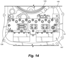
Figure 14 is an illustration showing an example positioning of the oil-cooled rectifier diode assembly ofFigure 12 within a generator housing - Reference will now be made to the drawings wherein like reference numerals identify similar structural features or aspects of the subject disclosure.
- As illustrated in
Figure 2 , and in accordance with one aspect of the present invention, an oil-cooledrectifier diode assembly 200 is illustrated. One ormore diodes 230 are arranged betweenbus bars first bus bar 210 includesfluid channels 215 formed therein, and can optionally include aparting sheet 217 to optimize fluid flow characteristics along the upper surface of thediode 230-- in this case, theanode 233. Similarly, thesecond bus bar 220 includesfluid channels 225 formed therein, and can also optionally include a parting sheet to close the lower end offluid channel 225 to optimize fluid flow characteristics. Thebus bars bus bars bus bars - An
insulating material 240 can be provided to stabilize thediodes 230, which itself can have cooling channels formed therethrough. Alternatively, these areas occupied by theinsulating material 240 can be left open to allow free passage of cooling fluid over the exposed surfaces of the diode(s) 230, anode(s) 233 and cathode(s) 235. - As will be further appreciated in discussion of alternate embodiments below, the quality of electrical and thermal contact between the
diode electrodes respective bus bars - With reference to
Figure 3 , an isometric view of an oil-cooledrectifier diode assembly 300 is illustrated, havingcooling fluid plenums bus bars supply plenum 350, from where it flows through channels formed inbus bars output plenum 360, from where the fluid returns to the cooling fluid circuit. In the illustrated embodiment, an alternate round cross-sectional geometry of cooling channels is shown. Such geometries can be fabricated in a conventional manner, such as by extrusion, and/or machining, or by newer technologies such as additive manufacturing techniques. Such techniques can be applied to all embodiments described herein. -
Figure 4 is a schematic cross-sectional end view of an oil-cooledrectifier diode assembly 400 in accordance with still another aspect of the present invention, including alternate arrangements forcooling channels bus bars - One or
more diodes 230 are arranged betweenbus bars first bus bar 410 includesfluid channels 415 formed therein. In this embodiment,channels 415 are spaced further apart than in the embodiment ofFigure 2 . Thefirst bus bar 410 can optionally include a parting sheet 417 to optimize fluid flow characteristics along the upper surface of thediode 230. - Similarly, the
second bus bar 420 includesfluid channels Figure 2 . Thesecond bus bar 420 can optionally include aparting sheet 427 to close the upper end offluid channel 425b to optimize fluid flow characteristics. Additionally, another parting sheet can be applied to the lower end offluid channels 425a. - As with other embodiments described herein, the bus bars 410, 420 can be formed by any suitable techniques, including but not limited to casting, extrusion and/or machining. Further the bus bars 410, 420 can each be formed of a single piece, or formed by joining multiple pieces together. The bus bars 410, 420 can be formed out of any preferably highly thermally and electrically conductive material. Copper and aluminum are preferred as practical choices, but other materials can be used, depending on the desired implementation.
- An insulating
material 440 can be provided to stabilize thediodes 230, which itself can have cooling channels formed therethrough. Alternatively, these areas occupied by the insulatingmaterial 440 can be left open to allow free passage of cooling fluid over the exposed surfaces of the diode(s) 230, anode(s) 233 and cathode(s) 235. The embodiment ofFigure 4 further includesadditional cooling channels 445 arranged between the insulatingmaterial 440 and thesecond bus bar 420.Such channels 445 can be defined simply by the boundary of the adjacent structures, or can alternatively be housed in a separate conduit. -
Figure 5 is a schematic cross-sectional end view of an oil-cooledrectifier diode assembly 500 in accordance with a further aspect of the present invention, in which a second level of one or more diodes is provided on the lower face of anintermediate bus bar 520, and athird bus bar 570 is also provided. In such an arrangement, theintermediate bus bar 520 can be utilized as the AC bus bar, with outer bus bars being utilized for DC. - One or
more diodes 230 are arranged in a first array betweenbus bars first bus bar 410 includesfluid channels 415 formed therein. The first bus bar 510 can optionally include a parting sheet to optimize fluid flow characteristics along the upper surface of thediode 230. Similarly, thesecond bus bar 520 includesfluid channels second bus bar 520 can optionally include a parting sheet to close the upper end offluid channel 525b and another parting sheet can be applied to the lower end offluid channels 525c to optimize fluid flow characteristics, if desired. - As used herein, the term "array" means an arrangement of one or more individual diodes. Such an array can include a single diode, or multiple diodes arranged in any pattern.
- Further, one or
more diodes 230 are arranged in a second array betweenbus bars third bus bar 570 includesfluid channels 515 formed therein. Thethird bus bar 570 can optionally include a parting sheet to optimize fluid flow characteristics along the lower surface of the adjacent diode(s) 230. - As with other embodiments described herein, the bus bars 410, 520, 570 can be formed by any suitable techniques, including but not limited to casting, extrusion and/or machining. Further the bus bars 410, 520, 570 can each be formed of a single piece, or formed by joining multiple pieces together. The bus bars 410, 520, 570 can be formed out of any preferably highly thermally and electrically conductive material. Copper and aluminum are preferred as practical choices, but other materials can be used, depending on the desired implementation.
- As with the embodiment of
Figure 4 , an insulatingmaterial 440 can be provided to stabilize thediodes 230, which itself can have cooling channels formed therethrough. Alternatively, the areas occupied by the insulatingmaterial 440 can be left open to allow free passage of cooling fluid over the exposed surfaces of the diode(s) 230, anode(s) 233 and cathode(s) 235. The embodiment ofFigure 5 further includesadditional cooling channels 445 arranged between the insulatingmaterial 440 and thesecond bus bar 420.Such channels 445 can be defined simply by the boundary of the adjacent structures, or can alternatively be housed in a separate conduit. -
Figure 6 is a top view of an oil-cooledrectifier diode assembly 600 in accordance with the present invention, illustrating bus bars 610 having cooling channels, andsupply plenum 350 andoutlet plenum 360.Figure 6 illustratesmultiple diodes 230 arranged in a linear array, and accordingly it is to be understood that the foregoing embodiments where only cross-sectional end views are shown can represent assemblies having any number of diodes arranged in line, or otherwise, along the common bus bars. - Moreover, this and other embodiments described herein can include diodes arranged laterally from those axially-offset
diodes 230 illustrated inFigure 6 . That is, where the embodimentFigure 3 could be described as having a 1x1 array ofdiodes 230, and the embodiment ofFigure 6 could be described as having a 1x6 array ofdiodes 230, all of the diodes being electrically connected in parallel to adjacent bus bars, alternate arrangements of diode arrays are possible and well within the scope of this application. For example, arrays of 2x6, 3x6, 3x3, 4x4, and so on are all possible, and advantageously can be selected based on power requirements, dimensional limitations and thermal characteristics, as needed. -
Figure 7-13 illustrate various components of an oil-cooledrectifier diode assembly 1200 in accordance with the invention. Of these,Figure 7 is an isometric view illustrating a middle orintermediate bus bar 720 composed ofstacked plates cooling channels middle bus bar 720a includes, extending off ofconnectors 723,power connections 727, whichconnections 727 are configured to receiveinsulators 729 to allow the connections to pass through adjacent bus bars (particularly first outer bus bar 810) having different polarity, as will be seen in connection with additional drawings described hereinbelow. In accordance with a preferred embodiment of the invention, sealing elements, in this case, O-rings 728 are provided to seal against the outer portions of the assembly. In this manner, loss of cooling fluid from the internal passageways is reduced, and component cooling is thereby enhanced. - As with the embodiment of
Figure 5 , a two levels ofdiodes 230 are provided, respectively on the upper and lower faces of theintermediate bus bar 720, although only the upper level is fully visible inFigure 7 . - The entire assembly of
Figure 7 is essentially held withinouter bus bars 810, 1070 (described in connection with the following figures), which form a fluid path around and through the assembly ofFigure 7 In that manner, theupper diodes 230 are arranged in a first array betweenouter bus bar 810 andinner bus bar 720, and thelower diodes 230 are arranged in a second array between theinner bus bar 720 and theouter bus bar 1070. - As best seen in
Figure 9 , the firstouter bus bar 810 includesfluid channels 815 formed therein. The firstouter bus bar 810 can optionally include a parting sheet to optimize fluid flow characteristics along the upper surface of thediode 230. Similarly, theinner bus bar 720 includesfluid channels inner bus bar 720 can optionally include a parting sheet to close the upper end offluid channel 525b and another parting sheet can be applied to the lower end offluid channels 525c to optimize fluid flow characteristics, if desired. Thethird bus bar 570 includesfluid channels 515 formed therein. Thethird bus bar 570 can optionally include a parting sheet to optimize fluid flow characteristics along the lower surface of the adjacent diode(s) 230. - As with other embodiments described herein, the bus bars 810, 720, 1070 can be formed by any suitable techniques, including but not limited to casting, extrusion and/or machining. Further the bus bars 810, 720, 1070 can each be formed of a single piece, or formed by joining multiple pieces together. The bus bars 810, 720, 1070 can be formed out of any preferably highly thermally and electrically conductive material. Copper and aluminum are preferred as practical choices, but other materials can be used, depending on the desired implementation.
- As with previously described embodiments, an insulating
material 740 can be provided to stabilize thediodes 230, which itself can have cooling channels formed therethrough. Alternatively, the areas occupied by the insulatingmaterial 740 can be left open to allow free passage of cooling fluid over the exposed surfaces of the diode(s) 230, anode(s) 233 and cathode(s) 235. - As with other embodiments having multiple levels of diodes, the diodes of one array are flipped with respect to the diodes of the opposing array, so that the polarity allows sharing of
intermediate bus bar 720, leaving theouter bus bars -
Figures 8 and9 are isometric views of outer and inner surfaces of the firstouter bus bar 810, respectively. Illustrated are coolingfluid inlet port 811 andvarious cutouts 813 to allow for passage of opposingbus bar connections 727 and theirinsulators 729. Notably, bolt holes 817 are also illustrated. With reference toFigure 9 , an integralcooling fluid channel 815 andsurface contours 812 to enhance mechanical, thermal and electrical connection to adjacent diodes are also illustrated. -
Figures 10 and11 are isometric views of inner and outer surfaces of the secondouter bus bar 1070, respectively. Illustrated are an integralcooling fluid channel 1075 andsurface contours 1072 to enhance mechanical, thermal and electrical connection to adjacent diodes. Bolt holes 1077 are also illustrated, along with coolingfluid outlet port 1071. -
Figure 12 is an isometric view of an assembled oil-cooledrectifier diode assembly 1200 in accordance with the invention. Additionally illustrated areassembly bolts 1218 and biasingmembers 1219 used to maintain contact force within the assembly betweenbus bars diodes 230. The biasingmembers 1219 can be any suitable resilient material, such as a spring or elastomeric washer, for example. In the illustrated embodiment, theassembly bolts 1218 pass from firstouter bus bar 810, through to the opposing secondouter bus bar 1070, and compress biasingmembers 1219 in the process, which maintain contact force between thediodes 230 andbus bars -
Figure 13 is a cross-sectional view of the oil-cooledrectifier diode assembly 1200, illustrating particularly acupped spring washer 1391, of which multiple can be provided along the length of theassembly 1200. The washers provide compression force to the components of theassembly 1200.Such washers 1391 can, generally, be referred to as "Belleville" type washers, for example. - In use, cooling fluid is directed from an cooling fluid system into the
inlet port 811, and distributed through the cooling channels of the bus bars 720, 810, 1070, exiting throughoutlet port 1071 back to the system. - As illustrated in
Figure 14 , if desired, the entirerectifier diode assembly 1200 can be wetted in engine sump oil to enhance cooling, depending on the application. As illustrated, therectifier 1200 is held within ahousing 1495, adjacent theconnected generator 1493. As such, circulating oil can advantageously be utilized for cooling of the rectifier through circulation intoport 811, and thereby through the above-discussed internal channels, and also through external contact with oil held within thesump area 1497. - Although it is conceived that the cooling fluid described herein will typically be oil, it should be understood that the present invention is not limited to using only oil. Typically, a dielectric oil operating in a wide temperature range will be selected, but any electrically nonconductive fluid can be used.
- While the devices, systems and methods of the subject disclosure have been shown and described with reference to embodiments, those skilled in the art will readily appreciate that changes and/or modifications may be made thereto without departing from the scope of the subject disclosure.
Claims (15)
- A liquid-cooled rectifier assembly (200, 300, 400, 500, 600, 1200) comprising:a first bus bar (210, 410, 510, 610, 810) having at least one cooling channel (215, 415, 515, 815) formed therein, adapted and configured to carry a cooling fluid therethrough;a second bus bar (220, 420, 520) having at least one cooling channel (225, 425a, 425b, 525a, 525b, 525c) formed therein, adapted and configured to carry the cooling fluid therethrough; anda first power diode array (230) arranged between and in contact with the first and second bus bars.
- The liquid-cooled rectifier assembly of claim 1, wherein the first (210, 410, 510, 610, 810) and second bus bars (220, 420, 520) define outer walls of a fluid chamber, cooling fluid entering the chamber and being distributed, at least in-part, through cooling channels formed in the first (210, 410, 510, 610, 810) and second bus bars (220, 420, 520).
- The liquid-cooled rectifier assembly of claim 1 or 2, wherein the first (210, 410, 510, 610, 810) and second bus bars (220, 420, 520) define outer walls of a fluid chamber, cooling fluid entering the chamber and being distributed, at least in-part, around the outer surface of the first power diode array (230).
- The liquid-cooled rectifier assembly of any preceding claim, the first bus bar (210, 410, 510, 610, 810) having a plurality of cooling channels (215, 415, 515, 815) formed therein.
- The liquid-cooled rectifier assembly of any preceding claim, the second bus bar (220, 420, 520) having a plurality of cooling channels (225, 425a, 425b, 525a, 525b, 525c) formed therein.
- The liquid-cooled rectifier assembly of any preceding claim, further comprising:
at least one bolt (1218), adapted and configured to compress the first and second bus bars onto the first power diode array (230), in order to optimize electrical and thermal contact between the first and second bus bars and the first power diode array; optionally further comprising:
at least one spring element (1219), adapted and configured to, in combination with the at least one bolt, compress the first and second bus bars onto the first power diode array, in order to optimize electrical and thermal contact between the first and second bus bars and the first power diode array. - The liquid-cooled rectifier assembly of claim 1, further comprising:a third bus bar (570) having at least one cooling channel (515) formed therein, adapted and configured to carry the cooling fluid therethrough; anda second power diode array (230) arranged between and in contact with the second and third bus bars.
- The liquid-cooled rectifier assembly of claim 7, the third bus bar (570) having a plurality of cooling channels (515) formed therein.
- The liquid-cooled rectifier assembly of claim 7 or 8, further comprising:
at least one bolt (1218), adapted and configured to compress the second and third bus bars onto the second power diode array (230), in order to optimize electrical and thermal contact between the second and third bus bars and the second power diode array. - The liquid-cooled rectifier assembly of claim 9, further comprising:
at least one spring element (1219), adapted and configured to, in combination with the at least one bolt, compress the second and third bus bars onto the second power diode array, in order to optimize electrical and thermal contact between the second and third bus bars and the second power diode array. - The liquid-cooled rectifier assembly of any of claims 7 to 10, wherein the first (520) and third bus bars (570) define outer walls of a fluid chamber, cooling fluid entering the chamber and being distributed, at least in-part, through cooling channels (252a, 525b, 525c, 515) formed in the first, second and third bus bars.
- The liquid-cooled rectifier assembly of any of claims 7 to 11, wherein the first (520) and third bus bars (570) are formed from aluminum or an aluminum alloy, and the second bus bar is formed from copper or a copper alloy.
- A method of cooling a rectifier diode assembly, comprising:providing a first bus bar having at least one cooling channel formed therein, adapted and configured to carry a cooling fluid therethrough;providing a second bus bar having at least one cooling channel formed therein, adapted and configured to carry the cooling fluid therethrough;providing a first power diode array arranged between and in contact with the first and second bus bars; andpassing a cooling fluid through the first and second bus bars, thereby cooling the first power diode array.
- The method of cooling a rectifier diode assembly of claim 13, wherein the cooling fluid is oil.
- The method of cooling a rectifier diode assembly of claim 14, wherein the oil is turbine sump oil.
Applications Claiming Priority (1)
| Application Number | Priority Date | Filing Date | Title |
|---|---|---|---|
| US18/088,194 US12382616B2 (en) | 2022-12-23 | 2022-12-23 | Oil-cooled rectifier diode assembly |
Publications (1)
| Publication Number | Publication Date |
|---|---|
| EP4391754A1 true EP4391754A1 (en) | 2024-06-26 |
Family
ID=88920823
Family Applications (1)
| Application Number | Title | Priority Date | Filing Date |
|---|---|---|---|
| EP23211325.8A Pending EP4391754A1 (en) | 2022-12-23 | 2023-11-21 | Oil-cooled rectifier diode assembly |
Country Status (2)
| Country | Link |
|---|---|
| US (1) | US12382616B2 (en) |
| EP (1) | EP4391754A1 (en) |
Families Citing this family (1)
| Publication number | Priority date | Publication date | Assignee | Title |
|---|---|---|---|---|
| US12568609B2 (en) * | 2023-07-11 | 2026-03-03 | Hamilton Sundstrand Corporation | Thermal management systems for rectifier assemblies |
Citations (4)
| Publication number | Priority date | Publication date | Assignee | Title |
|---|---|---|---|---|
| JP2005057130A (en) * | 2003-08-06 | 2005-03-03 | Denso Corp | Semiconductor cooling unit |
| US20100302733A1 (en) * | 2009-05-29 | 2010-12-02 | Gm Global Technology Operations, Inc. | Stacked busbar assembly with integrated cooling |
| US20140319673A1 (en) * | 2011-11-07 | 2014-10-30 | Daikin Industries, Ltd. | Semiconductor device |
| DE102019203399A1 (en) * | 2019-03-13 | 2020-09-17 | Mahle International Gmbh | Electric busbar arrangement |
Family Cites Families (13)
| Publication number | Priority date | Publication date | Assignee | Title |
|---|---|---|---|---|
| US3333163A (en) * | 1965-02-15 | 1967-07-25 | Int Rectifier Corp | Rectifier assembly with interconnecting bus-bar supports |
| US4896062A (en) * | 1988-06-03 | 1990-01-23 | Westinghouse Electric Corp. | Rotating rectifier assembly |
| US4975825A (en) * | 1990-01-16 | 1990-12-04 | Sundstrand Corporation | Stacked power converter |
| WO1995034438A1 (en) * | 1994-06-10 | 1995-12-21 | Westinghouse Electric Corporation | Electrical vehicle propulsion system |
| US6016007A (en) * | 1998-10-16 | 2000-01-18 | Northrop Grumman Corp. | Power electronics cooling apparatus |
| US20090052134A1 (en) | 2007-08-22 | 2009-02-26 | Casteel Jordan B | Liquid-cooled grounded heatsink for diode rectifier system |
| US7916480B2 (en) * | 2007-12-19 | 2011-03-29 | GM Global Technology Operations LLC | Busbar assembly with integrated cooling |
| US9035507B2 (en) | 2013-01-29 | 2015-05-19 | Aviation Systems, LLC | Electric machine and rectifier assembly therefor |
| US10103604B2 (en) | 2014-07-11 | 2018-10-16 | Ge Aviation Systems Llc | Rotating rectifier assembly for electric machine |
| US10057974B2 (en) | 2016-11-04 | 2018-08-21 | Hamilton Sundstrand Corporation | Integrated panel level liquid cooling for bus bars |
| EP3696877A1 (en) * | 2019-02-18 | 2020-08-19 | 3M Innovative Properties Company | Battery module |
| JP7127633B2 (en) * | 2019-11-05 | 2022-08-30 | 株式会社デンソー | sensor unit |
| US11735980B2 (en) | 2020-12-29 | 2023-08-22 | Hamilton Sundstrand Corporation | Anti-rotation feature for bonded stud |
-
2022
- 2022-12-23 US US18/088,194 patent/US12382616B2/en active Active
-
2023
- 2023-11-21 EP EP23211325.8A patent/EP4391754A1/en active Pending
Patent Citations (4)
| Publication number | Priority date | Publication date | Assignee | Title |
|---|---|---|---|---|
| JP2005057130A (en) * | 2003-08-06 | 2005-03-03 | Denso Corp | Semiconductor cooling unit |
| US20100302733A1 (en) * | 2009-05-29 | 2010-12-02 | Gm Global Technology Operations, Inc. | Stacked busbar assembly with integrated cooling |
| US20140319673A1 (en) * | 2011-11-07 | 2014-10-30 | Daikin Industries, Ltd. | Semiconductor device |
| DE102019203399A1 (en) * | 2019-03-13 | 2020-09-17 | Mahle International Gmbh | Electric busbar arrangement |
Also Published As
| Publication number | Publication date |
|---|---|
| US12382616B2 (en) | 2025-08-05 |
| US20240215210A1 (en) | 2024-06-27 |
Similar Documents
| Publication | Publication Date | Title |
|---|---|---|
| US5586004A (en) | Mounting assembly for power semiconductors | |
| KR101633943B1 (en) | Flexible voltage nested battery module design | |
| US5504378A (en) | Direct cooled switching module for electric vehicle propulsion system | |
| US10991639B2 (en) | Compliant Pin Fin heat sink with base integral pins | |
| EP3236725B1 (en) | Power electronics module | |
| US11864357B2 (en) | Double-sided cooling cold plates with overhanging heat sinks and through body busbar for high-power density power electronics | |
| JP5855662B2 (en) | Thermoelectric devices, in particular thermoelectric devices for generating electric currents in automobiles | |
| JP2013543656A (en) | Thermoelectric devices, in particular thermoelectric devices for generating current in automobiles | |
| US12382616B2 (en) | Oil-cooled rectifier diode assembly | |
| JP7674520B2 (en) | Battery system having a battery module | |
| US20240015881A1 (en) | Printed circuit board (pcb) cooling | |
| US11856689B2 (en) | Power electronics assemblies and methods of fabricating the same | |
| EP4443718A1 (en) | Rectifier diode assembly | |
| CN113396310A (en) | Power converter with integrated multi-layer cooling | |
| US5953201A (en) | Capacitors with through-bores for fastening means | |
| WO2024141779A1 (en) | Battery pack with internal heat transfer fluid distribution | |
| JP6009534B2 (en) | Thermoelectric assembly and apparatus for generating current, particularly in motor vehicles | |
| US20240381569A1 (en) | Cooler for cooling power electronics | |
| EP4184662A2 (en) | Battery module with heat pipes | |
| US3304207A (en) | Thermoelectric generator | |
| DE102017216732A1 (en) | Power converter, electric drive arrangement with a power converter | |
| KR102915760B1 (en) | Heating element cooling structure | |
| CN219576843U (en) | Power supply device | |
| EP4369872A1 (en) | Solid state power switch assembly of an aircraft solid state power controller and method of providing a solid state power switch assembly for an aircraft solid state power controller | |
| JP2023129203A (en) | semiconductor equipment |
Legal Events
| Date | Code | Title | Description |
|---|---|---|---|
| PUAI | Public reference made under article 153(3) epc to a published international application that has entered the european phase |
Free format text: ORIGINAL CODE: 0009012 |
|
| STAA | Information on the status of an ep patent application or granted ep patent |
Free format text: STATUS: THE APPLICATION HAS BEEN PUBLISHED |
|
| AK | Designated contracting states |
Kind code of ref document: A1 Designated state(s): AL AT BE BG CH CY CZ DE DK EE ES FI FR GB GR HR HU IE IS IT LI LT LU LV MC ME MK MT NL NO PL PT RO RS SE SI SK SM TR |
|
| STAA | Information on the status of an ep patent application or granted ep patent |
Free format text: STATUS: REQUEST FOR EXAMINATION WAS MADE |
|
| 17P | Request for examination filed |
Effective date: 20241204 |
|
| RBV | Designated contracting states (corrected) |
Designated state(s): AL AT BE BG CH CY CZ DE DK EE ES FI FR GB GR HR HU IE IS IT LI LT LU LV MC ME MK MT NL NO PL PT RO RS SE SI SK SM TR |