EP4391678A1 - Signal transmission power control method and apparatus - Google Patents
Signal transmission power control method and apparatus Download PDFInfo
- Publication number
- EP4391678A1 EP4391678A1 EP22857349.9A EP22857349A EP4391678A1 EP 4391678 A1 EP4391678 A1 EP 4391678A1 EP 22857349 A EP22857349 A EP 22857349A EP 4391678 A1 EP4391678 A1 EP 4391678A1
- Authority
- EP
- European Patent Office
- Prior art keywords
- prs
- transmission power
- path loss
- sidelink
- pssch
- Prior art date
- Legal status (The legal status is an assumption and is not a legal conclusion. Google has not performed a legal analysis and makes no representation as to the accuracy of the status listed.)
- Pending
Links
Images


Classifications
-
- H—ELECTRICITY
- H04—ELECTRIC COMMUNICATION TECHNIQUE
- H04W—WIRELESS COMMUNICATION NETWORKS
- H04W52/00—Power management, e.g. Transmission Power Control [TPC] or power classes
- H04W52/04—Transmission power control [TPC]
- H04W52/38—TPC being performed in particular situations
- H04W52/383—TPC being performed in particular situations power control in peer-to-peer links
-
- H—ELECTRICITY
- H04—ELECTRIC COMMUNICATION TECHNIQUE
- H04W—WIRELESS COMMUNICATION NETWORKS
- H04W52/00—Power management, e.g. Transmission Power Control [TPC] or power classes
- H04W52/04—Transmission power control [TPC]
- H04W52/18—TPC being performed according to specific parameters
- H04W52/24—TPC being performed according to specific parameters using SIR [Signal to Interference Ratio] or other wireless path parameters
- H04W52/246—TPC being performed according to specific parameters using SIR [Signal to Interference Ratio] or other wireless path parameters where the output power of a terminal is based on a path parameter calculated in said terminal
-
- H—ELECTRICITY
- H04—ELECTRIC COMMUNICATION TECHNIQUE
- H04W—WIRELESS COMMUNICATION NETWORKS
- H04W52/00—Power management, e.g. Transmission Power Control [TPC] or power classes
- H04W52/04—Transmission power control [TPC]
- H04W52/18—TPC being performed according to specific parameters
- H04W52/24—TPC being performed according to specific parameters using SIR [Signal to Interference Ratio] or other wireless path parameters
- H04W52/242—TPC being performed according to specific parameters using SIR [Signal to Interference Ratio] or other wireless path parameters taking into account path loss
-
- H—ELECTRICITY
- H04—ELECTRIC COMMUNICATION TECHNIQUE
- H04W—WIRELESS COMMUNICATION NETWORKS
- H04W52/00—Power management, e.g. Transmission Power Control [TPC] or power classes
- H04W52/04—Transmission power control [TPC]
- H04W52/30—Transmission power control [TPC] using constraints in the total amount of available transmission power
- H04W52/32—TPC of broadcast or control channels
- H04W52/325—Power control of control or pilot channels
-
- H—ELECTRICITY
- H04—ELECTRIC COMMUNICATION TECHNIQUE
- H04W—WIRELESS COMMUNICATION NETWORKS
- H04W72/00—Local resource management
- H04W72/04—Wireless resource allocation
-
- H—ELECTRICITY
- H04—ELECTRIC COMMUNICATION TECHNIQUE
- H04W—WIRELESS COMMUNICATION NETWORKS
- H04W52/00—Power management, e.g. Transmission Power Control [TPC] or power classes
- H04W52/04—Transmission power control [TPC]
- H04W52/06—TPC algorithms
- H04W52/10—Open loop power control
-
- H—ELECTRICITY
- H04—ELECTRIC COMMUNICATION TECHNIQUE
- H04W—WIRELESS COMMUNICATION NETWORKS
- H04W52/00—Power management, e.g. Transmission Power Control [TPC] or power classes
- H04W52/04—Transmission power control [TPC]
- H04W52/30—Transmission power control [TPC] using constraints in the total amount of available transmission power
- H04W52/34—TPC management, i.e. sharing limited amount of power among users or channels or data types, e.g. cell loading
- H04W52/343—TPC management, i.e. sharing limited amount of power among users or channels or data types, e.g. cell loading taking into account loading or congestion level
-
- H—ELECTRICITY
- H04—ELECTRIC COMMUNICATION TECHNIQUE
- H04W—WIRELESS COMMUNICATION NETWORKS
- H04W52/00—Power management, e.g. Transmission Power Control [TPC] or power classes
- H04W52/04—Transmission power control [TPC]
- H04W52/30—Transmission power control [TPC] using constraints in the total amount of available transmission power
- H04W52/36—Transmission power control [TPC] using constraints in the total amount of available transmission power with a discrete range or set of values, e.g. step size, ramping or offsets
- H04W52/367—Power values between minimum and maximum limits, e.g. dynamic range
Definitions
- the resent disclosure relates to the technical field of communications, and in particular to a method and apparatus for controlling signal transmission power.
- a downlink positioning reference signal and an uplink positioning reference signal are only defined in an air interface between a base station and a terminal, and no sidelink positioning reference signal is defined in a PC5 interface between terminals.
- the terminal needs to rely on the base station to achieve positioning, and the positioning process cannot be completed in the sidelink.
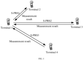
- a terminal 1 sends a sidelink positioning reference signal to terminals 2 to 4, realizing a schematic diagram of the positioning process of the terminal 1.
- the terminal 1 may be referred to as a sending terminal or a transmitting terminal.
- the terminals 2 to 4 may be referred to as receiving terminals.
- the terminal 1 may send a Sidelink Positioning Reference Signal (S-PRS) to the terminals 2 to 4.
- S-PRS Sidelink Positioning Reference Signal
- the terminals 2 to 4 measure the S-PRS and send measurement results to UE1, to assist UE1 to complete the positioning calculation.
- the terminal sends the sidelink positioning reference signal with a fixed power without controlling the S-PRS transmission power
- the sending terminal and the receiving terminal of the S-PRS are close to each other (as shown between the terminal 1 and the terminal 2 in FIG. 1 )
- the sidelink path loss is very small, which may cause the S-PRS transmission power of the terminal to exceed the required power, causing serious mutual interference between S-PRSs between the terminals and affecting the positioning precision of the sidelink.
- the sending terminal and the receiving terminal of the S-PRS are far away from each other (as shown between the terminal 1 and the terminal 3 in FIG. 1 )
- the sidelink path loss is very large, which may cause the S-PRS transmission power of the terminal to fail to reach the required power, causing insufficient coverage of S-PRS and affecting the positioning precision of the sidelink.
- Embodiments of the present disclosure provides a method and apparatus for controlling signal transmission power, for realizing control of transmission power of a sidelink positioning reference signal through a transmission power control parameter, improving the positioning precision of the sidelink.
- a method for controlling signal transmission power includes:
- the transmission power control parameter is determined; the transmission power of the sidelink positioning reference signal, S-PRS, is determined according to the transmission power control parameter, the sending terminal sends the S-PRS to the receiving terminal using the transmission power, realizing the control of the transmission power of the sidelink positioning reference signal through the transmission power control parameter, and improving the positioning precision of the sidelink.
- the transmission power control parameter includes one or a combination of following parameters:
- the S-PRS and the physical sidelink share channel, PSSCH are not sent on a same symbol.
- the S-PRS and the physical sidelink share channel, PSSCH are sent on a same symbol.
- the S-PRS is not sent on a symbol same as a symbol at which at least one of a physical sidelink control channel, PSCCH, or a physical sidelink feedback channel PSFCH is sent.
- an apparatus for controlling signal transmission power includes:
- the transmission power control parameter includes one or a combination of following parameters:
- the S-PRS and the physical sidelink share channel, PSSCH are not sent on a same symbol.
- the S-PRS and the physical sidelink share channel, PSSCH are sent on a same symbol.
- the S-PRS is not sent on a symbol same as a symbol at which at least one of a physical sidelink control channel, PSCCH, or a physical sidelink feedback channel PSFCH is sent.
- another apparatus for controlling signal transmission power includes:
- Another embodiment of that present disclosure provides a computer storage medium, storing computer-executable instruction thereon, the computer-executable instructions being configured to cause a computer to perform any one of the above methods.
- Embodiments of the present disclosure provide a method and apparatus for controlling signal transmission power, for realizing the control of the transmission power of the sidelink positioning reference signal through the transmission power control parameter, improving the positioning precision of the sidelink.
- the method and the apparatus are based on the same inventive conception. Since principles of the method and the apparatus for solving problems are similar, implementations of the apparatus and the method may refer to each other, and repetitions are omitted.
- applicable systems may be a global system of mobile communication (GSM) system, a code division multiple access (CDMA) system, a wideband code division multiple access (WCDMA) system, a general packet radio service (GPRS) system, a long term evolution (LTE) system, an LTE frequency division duplex (FDD) system, a LTE time division duplex (TDD), an universal mobile telecommunication system (UMTS), a worldwide interoperability for microwave access (WiMAX) system, a 5G system and a 5G NR system, etc.
- GSM global system of mobile communication
- CDMA code division multiple access
- WCDMA wideband code division multiple access
- GPRS general packet radio service
- LTE long term evolution
- FDD LTE frequency division duplex
- TDD LTE time division duplex
- UMTS universal mobile telecommunication system
- WiMAX worldwide interoperability for microwave access
- 5G system and a 5G NR system etc.
- the various systems each include a terminal device and a
- the terminal device involved in embodiments of the present disclosure may be referred to a device that provides voice and/or data connectivity to users, a handheld device with a wireless connection function, or other processing device connected to a wireless modem.
- names of the terminal device may be different.
- the terminal device may be called user equipment (UE).
- the wireless terminal device may communicate with one or more core networks via a RAN, and the wireless terminal device may be a mobile terminal device such as a mobile phone (or referred to a "cellular" phone) and a computer with a mobile terminal device, for example, which may be portable, pocket, handheld, computer built-in or vehicle mounted mobile devices that exchange language and/or data with a radio access network.
- a personal communication service (PCS) phone For example, a personal communication service (PCS) phone, a cordless phones, a session initiated protocol (SIP) phone, a wireless local loop (WLL) station, a personal digital assistant (PDA) and other devices.
- the wireless terminal device may also be referred to as a system, a subscriber unit, a subscriber station, a mobile station, a mobile, a remote station, an access point, a remote terminal, an access terminal, a user terminal, a user agent, and a user device, which are not limited in embodiments of the present disclosure.
- the network device involved in embodiments of the present disclosure may be a base station, and the base station may include a plurality of cells.
- the base station may also be referred to as an access point, or may refer to a device that communicates with the wireless terminal device through one or more sectors on an air interface in the access network, or other names.
- the network device may be configured to interconvert received air frames and internet protocol (IP) packets, and act as a router between the wireless terminal device and the rest of the access network, where the rest of the access network may include an internet protocol (IP) communication network.
- IP internet protocol
- the network device may also coordinate attribute management for the air interface.
- the network device involved in embodiments of the present disclosure may be a base transceiver station (BTS) in a global system for mobile communications (GSM) or a code division multiple access (CDMA), or a network device (NodeB) in wide-band code division multiple access (WCDMA), or an evolutional node B (eNB or e-NodeB) in a long term evolution (LTE) system, or a 5G base station in 5G network architecture (a next generation system), a home evolved node B (HeNB), relay node (relay node), a home base station (femto), a pico base station (pico), etc., which are not limited in embodiments of the present disclosure.
- BTS base transceiver station
- GSM global system for mobile communications
- CDMA code division multiple access
- NodeB network device
- WCDMA wide-band code division multiple access
- eNB or e-NodeB evolutional node B
- LTE long term evolution
- Embodiments of the present disclosure provide a power control scheme for a sidelink positioning reference signal of a terminal suitable for sidelink, the sending terminal can determine the transmission power of the sidelink positioning reference signal, S-PRS, according to the transmission power control parameter, and sends the S-PRS to the receiving terminal using the transmission power.
- the transmission power control parameter includes one or more pieces of information of, for example, maximum transmission power P CMAX of a sending terminal, a power control configuration parameter P 0 of the sidelink positioning reference signal, a partial path loss compensation factor ⁇ of the sidelink positioning reference signal , a quantity M of resource blocks occupied by the sidelink positioning reference signal, a sidelink path loss PL SL , a downlink path loss PL DL , an uplink path loss PL UL , a channel busy ratio CBR, transmission power P PSSCH of a physical sidelink shared channel, or the like.
- the transmission power P S-PRS of the sidelink positioning reference signal is determined using one or more of these pieces of information.
- Embodiments of the present disclosure use the method to ensure that the terminal can determine the appropriate transmission power of the sidelink positioning reference signal, reducing the mutual interference between the sidelink positioning reference signals sent between the terminals, improving the positioning precision of the sidelink by the terminal.
- the terminal controls the transmission power of the S-PRS according to various power control parameters
- the sending terminal and the receiving terminal of the S-PRS are close to each other (as shown between the terminal 1 and the terminal 2 in FIG. 1 )
- the sidelink path loss is very small, and the terminal uses a small S-PRS transmission power, avoiding the serious mutual interference between S-PRSs between the terminals, and further ensuring the high positioning precision of the sidelink.
- the sending terminal and the receiving terminal of the S-PRS are far away from each other (as shown between the terminal 1 and the terminal 3 in FIG.
- the sidelink path loss is very large, and the terminal uses a large S-PRS transmission power, ensuring the coverage of the S-PRS and the high positioning precision of the sidelink.
- the terminal calculates the transmission power of the S-PRS the downlink path loss or the uplink path loss with the base station may also be considered simultaneously, avoiding the influence on the air interface communication between the base station and the terminal when the terminal transmits the S-PRS.
- the sidelink path loss PL SL refers to the sidelink path loss between the S-PRS sending terminal and the S-PRS receiving terminal.
- the downlink path loss PL DL refers to the air interface downlink path loss from a base station or a cell to the S-PRS sending terminal.
- the uplink path loss PL UL refers to the air interface downlink path loss from the S-PRS sending terminal to a base station or a cell.
- the specific power control schemes for the S-PRS are as follows.
- the complete path loss compensation means that when calculating the S-PRS transmission power, a value of all path losses is compensated to the transmission power according to the path loss between the S-PRS sending end and the S-PRS receiving end. For example, if the path loss is 100dB, the transmission power should be increased by 100dB accordingly, instead of a value less than 100dB.
- PL is any one path loss of a sidelink path loss, a downlink path loss and an uplink path loss, or is a function value with at least one path loss of the sidelink path loss, the downlink path loss or the uplink path loss as an independent variable.
- S-PRS power control scheme 2 (single path loss determination method + with CBR) is as follows.
- S-PRS power control scheme 3 (dual path loss determination method + no CBR) is as follows.
- S-PRS power control scheme 4 (dual path loss determination method + with CBR) is as follows.
- S-PRS power control scheme 5 (data channel determination method + different symbol transmission) is as follows.
- S-PRS power control scheme 6 (data channel determination method + same symbol transmission) is as follows.
- Applicable scenario simultaneous transmission of S-PRS and PSSCH.
- i is any integer greater than or equal to 0, values of i described in different positions in the description may be different.
- a sending terminal selects and uses a suitable S-PRS power control scheme according to the multiplexing condition of the same symbol of the S-PRS and the PSSCH.
- the sending terminal uses the above S-PRS power control schemes 1 to 5, to perform transmission power control on the S-PRS.
- the sending terminal uses the above S-PRS power control scheme 6, to perform transmission power control on the S-PRS.
- the S-PRS is not sent on the same symbol as at least one channel of Physical Sidelink Control Channel (PSCCH) or Physical Sidelink Feedback Channel (PSFCH).
- PSCCH Physical Sidelink Control Channel
- PSFCH Physical Sidelink Feedback Channel
- Embodiment 1 S-PRS power control scheme 1 (single path loss determination method + no CBR)) is as follows.
- Transmission power P S-PRS of a sidelink positioning reference signal is determined accordingto information such as maximum transmission power P CMAX of a sending terminal, a power control configuration parameter P 0 of the sidelink positioning reference signal, a partial path loss compensation factor ⁇ of the sidelink positioning reference signal, a quantity M of resource blocks occupied by the sidelink positioning reference signal, a sidelink path loss PL SL , a downlink path loss PL DL , an uplink path loss PL UL , or the like.
- the sending terminal sends the sidelink positioning reference signal (S-PRS) with the determined transmission power P S-PRS .
- the PL in the above formula is any one path loss of a sidelink path loss, a downlink path loss and an uplink path loss, or is a function value with at least one path loss of the sidelink path loss, the downlink path loss or the uplink path loss as an independent variable.
- Any combination of a plurality of path losses means that a certain mixed path loss is calculated with at least one of path loss the sidelink path loss PL SL , the downlink path loss PL DL , or the uplink path loss PL UL as parameters.
- the terminal can flexibly determine the appropriate transmission power of the sidelink positioning reference signal according to respective parameters of the wireless transmission and the mixed path loss, reducing the mutual interference between the sidelink positioning reference signals sent between the terminals, and improving the positioning precision of the sidelink by the terminal.
- Embodiment 2 S-PRS power control scheme 2 (single path loss determination method + with CBR)) is as follows.
- Transmission power P S-PRS of a sidelink positioning reference signal is determined according to information such as maximum transmission power P CMAX of a sending terminal, a power control configuration parameter P 0 of the sidelink positioning reference signal, a partial path loss compensation factor ⁇ of the sidelink positioning reference signal , a quantity M of resource blocks occupied by the sidelink positioning reference signal, a sidelink path loss PL SL , a downlink path loss PL DL , an uplink path loss PL UL , a channel busy ratio CBR, or the like.
- the sending terminal sends the sidelink positioning reference signal (S-PRS) with the determined transmission power P S-PRS .
- the parameter CBR refers to a channel occupation ratio in a resource pool in a historical time window measured by the terminal, and is a characterization parameter of a congestion degree of a current resource pool. Different CBR value intervals correspond to different maximum transmission powers of the terminal.
- CBR Serial number Maximum transmission power P MAX,CBR of the terminal CBR interval
- CBR power maximum transmission P MAX,CBR of the terminal 1 23dBm [CBR ⁇ 0.5] 23dBm 2 23dBm [0.5 ⁇ CBR ⁇ 0.6] 22dBm 3 23dBm [0.6 ⁇ CBR ⁇ 0.7] 21dBm 4 23dBm [0.7 ⁇ CBR ⁇ 0.8] 19dBm 5 23dBm [0.8 ⁇ CBR ⁇ 0.9] 17dBm 6 23dBm [CBR>0.9] 15dBm
- the PL in the above formula is any one path loss of a sidelink path loss, a downlink path loss and an uplink path loss, or is a function value with at least one path loss of the sidelink path loss, the downlink path loss or the uplink path loss as an independent variable.
- Any combination of a plurality of path losses means that a certain mixed path loss is calculated with at least one of path loss the sidelink path loss PL SL , the downlink path loss PL DL , or the uplink path loss PL UL as parameters.
- PL min(PL SL , PL DL , PL UL ).
- the terminal can flexibly determine the appropriate transmission power of the sidelink positioning reference signal according to respective parameters of the wireless transmission, CBR and the mixed path loss, reducing the mutual interference between the sidelink positioning reference signals sent between the terminals, and improving the positioning precision of the sidelink by the terminal.
- Embodiment 3 S-PRS power control scheme 3 (dual path loss determination method + no CBR) is as follows.
- Transmission power P S-PRS of a sidelink positioning reference signal is determined according to information such as maximum transmission power P CMAX of a sending terminal, a power control configuration parameter P 0 of the sidelink positioning reference signal, a partial path loss compensation factor ⁇ of the sidelink positioning reference signal , a quantity M of resource blocks occupied by the sidelink positioning reference signal, a sidelink path loss PL SL , a downlink path loss PL DL , an uplink path loss PL UL , or the like.
- the sending terminal sends the sidelink positioning reference signal (S-PRS) with the determined transmission power P S-PRS .
- the S-PRS power control scheme described in this embodiment is to first calculate the transmission power P S-PRS,D (i) and P S-PRS,SL (i) of the S-PRS according to the downlink path loss and the sidelink path loss respectively, and then calculate the final transmission power of the S-PRS according to the above formula.
- P S-PRS,D (i) and P S-PRS,SL (i) are calculated as follows.
- P S ⁇ PRS , D i P O , D + 10 log 10 2 ⁇ ⁇ M RB S ⁇ PRS i + ⁇ D ⁇ PL D dBm ;
- the terminal can flexibly determine the appropriate transmission power of the sidelink positioning reference signal according to respective parameters of the wireless transmission, and the downlink path loss/sidelink path loss, reducing the mutual interference between the sidelink positioning reference signals sent between the terminals, and improving the positioning precision of the sidelink by the terminal.
- Embodiment 4 S-PRS power control scheme 4 (dual path loss determination method + with CBR) is as follows.
- Transmission power P S-PRS of a sidelink positioning reference signal is determined according to information such as maximum transmission power P CMAX of a sending terminal, a power control configuration parameter P 0 of the sidelink positioning reference signal, a partial path loss compensation factor ⁇ of the sidelink positioning reference signal , a quantity M of resource blocks occupied by the sidelink positioning reference signal, a sidelink path loss PL SL , a downlink path loss PL DL , an uplink path loss PL UL , a channel busy ratio (CBR), or the like.
- the sending terminal sends the sidelink positioning reference signal (S-PRS) with the determined transmission power P S-PRS .
- the S-PRS power control scheme described in this embodiment is to first calculate the transmission power P S-PRS,D (i) and P S-PRS,SL (i) of the S-PRS according to the downlink path loss and the sidelink path loss respectively, and then calculate the final transmission power of the S-PRS according to the above formula.
- P S ⁇ PRS , D i and P S ⁇ PRS , SL i are calculated as follows.
- P S ⁇ PRS , D i P O , D + 10 log 10 2 ⁇ ⁇ M RB S ⁇ PRS i + ⁇ D ⁇ PL D dBm ; where:
- the parameter CBR refers to a channel occupation ratio in a resource pool in a historical time window measured by the terminal, and is a characterization parameter of a congestion degree of a current resource pool. Different CBR value intervals correspond to different maximum transmission powers of the terminal.
- CBR Serial number Maximum transmission power P MAX,CBR of the terminal CBR interval
- CBR maximum transmission power P MAX,CBR of the terminal 1 23dBm [CBR ⁇ 0.5] 23dBm 2 23dBm [0.5 ⁇ CBR ⁇ 0.6] 22dBm 3 23dBm [0.6 ⁇ CBR ⁇ 0.7] 21dBm 4 23dBm [0.7 ⁇ CBR ⁇ 0.8] 19dBm 5 23dBm [0.8 ⁇ CBR ⁇ 0.9] 17dBm 6 23dBm [CBR>0.9] 15dBm
- the terminal can flexibly determine the appropriate transmission power of the sidelink positioning reference signal according to respective parameters of the wireless transmission, CBR and the downlink path loss/sidelink path loss, reducing the mutual interference between the sidelink positioning reference signals sent between the terminals, and improving the positioning precision of the sidelink by the terminal.
- Embodiment 5 S-PRS power control scheme 5 (data channel determination method + different symbol transmission) is as follows.
- Transmission power P S-PRS of a sidelink positioning reference signal is determined according to information such as maximum transmission power P CMAX of a sending terminal, a quantity M of resource blocks occupied by the sidelink positioning reference signal, transmission power P PSSCH of a sidelink physical sharing channel, or the like.
- the sending terminal sends the sidelink positioning reference signal (S-PRS) with the determined transmission power P S-PRS .
- the S-PRS transmission power control scheme described in this embodiment is an indirect power control scheme, that is, the transmission power of the S-PRS is not calculated through various parameters of pre-configuration or high-level signaling configuration, but the transmission power of the S-PRS is indirectly obtained through the transmission power of the PSSCH data channel sent in the same time slot i, combined with the quantity of Resource blocks (RBs) occupied by the S-PRS and the PSSCH.
- the transmission power of the S-PRS is not calculated through various parameters of pre-configuration or high-level signaling configuration, but the transmission power of the S-PRS is indirectly obtained through the transmission power of the PSSCH data channel sent in the same time slot i, combined with the quantity of Resource blocks (RBs) occupied by the S-PRS and the PSSCH.
- RBs Resource blocks
- the S-PRS and the PSSCH are sent in the same time slot i, the S-PRS and the PSSCH do not occupy the same symbol. So the maximum possible transmission power of the S-PRS is P CMAX .
- the terminal can indirectly obtain the transmission power of the S-PRS according to the transmission power of the PSSCH data channel sent in the same time slot i, combined with the RB quantities occupied by the S-PRS and the PSSCH, reducing the mutual interference between the sidelink positioning reference signals sent between the terminals, and improving the positioning precision of the sidelink by the terminal.
- a large amount of power control parameters are not required to be acquired in advance, and signaling overhead is relatively small.
- Embodiment 6 S-PRS power control scheme 6 (data channel determination method + same symbol transmission) is as follows.
- Transmission power P S-PRS of a sidelink positioning reference signal is determined according to information such as maximum transmission power P CMAX of a sending terminal, a quantity M of resource blocks occupied by the sidelink positioning reference signal, transmission power P PSSCH of a sidelink physical sharing channel, or the like.
- the sending terminal sends the sidelink positioning reference signal (S-PRS) with the determined transmission power P S-PRS .
- the S-PRS transmission power control scheme described in this embodiment is an indirect power control scheme, that is, the transmission power of the S-PRS is not calculated through various parameters of pre-configuration or high-level signaling configuration, but the transmission power of the S-PRS is indirectly obtained through the transmission power of the PSSCH data channel sent in the same time slot i, combined with the quantity of Resource blocks (RBs) occupied by the S-PRS and the PSSCH.
- the transmission power of the S-PRS is not calculated through various parameters of pre-configuration or high-level signaling configuration, but the transmission power of the S-PRS is indirectly obtained through the transmission power of the PSSCH data channel sent in the same time slot i, combined with the quantity of Resource blocks (RBs) occupied by the S-PRS and the PSSCH.
- RBs Resource blocks
- the terminal can indirectly obtain the transmission power of the S-PRS according to the transmission power of the PSSCH data channel sent in the same time slot i, combined with the RB quantities occupied by the S-PRS and the PSSCH, reducing the mutual interference between the sidelink positioning reference signals sent between the terminals, and improving the positioning precision of the sidelink by the terminal.
- a large amount of power control parameters are not required to be acquired in advance, and signaling overhead is relatively small.
- Embodiment 7 (multiplexing scheme of S-PRS and PSSCH/PSCCH/PSFCH) is as follows.
- a sending terminal selects and uses a suitable S-PRS power control scheme according to the multiplexing condition of the same symbol of the S-PRS and the PSSCH.
- the sending terminal uses the above S-PRS power control schemes 1 to 5, to perform transmission power control on the S-PRS.
- the sending terminal uses the above S-PRS power control scheme 6, to perform transmission power control on the S-PRS.
- the above S-PRS power control selection schemes are used because the S-PRS may be sent on the same symbol as the PSSCH for frequency division multiplexing, and the S-PRS may also be sent on different symbols from the PSSCH for time division multiplexing. If the S-PRS and the PSSCH are not sent on the same symbol, the maximum transmission power of the S-PRS is P CMAX . If the S-PRS and the PSSCH are sent on the same symbol, the maximum transmission power of the S-PRS is P CMAX - P PSSCH (i).
- S-PRS and control channels such as PSCCH/PSFCH
- S-PRS and at least one channel such as PSCCH and PSFCH are not sent on the same symbol. In this way, the S-PRS transmission can be prevented from occupying the power of the control channel, and the interference to the control channel can also be avoided.
- a suitable multiplexing scheme can be flexibly selected according to different types of sidelink channels, which can not only ensure the S-PRS has enough time-frequency resources to use, but also ensure the transmission success rate of the control channel.
- a method for controlling signal transmission power includes following steps.
- the transmission power control parameter includes one or a combination of following parameters:
- the S-PRS and the physical sidelink share channel, PSSCH are not sent on a same symbol.
- the S-PRS and the physical sidelink share channel, PSSCH are sent on a same symbol.
- the S-PRS is not sent on a same symbol as at least one of a physical sidelink control channel, PSCCH, or a physical sidelink feedback channel PSFCH.
- an apparatus for controlling signal transmission power includes:
- the transmission power control parameter includes one or a combination of following parameters:
- the S-PRS and the physical sidelink share channel, PSSCH are not sent on a same symbol.
- the S-PRS and the physical sidelink share channel, PSSCH are sent on a same symbol.
- the S-PRS is not sent on a same symbol as at least one of a physical sidelink control channel, PSCCH, or a physical sidelink feedback channel PSFCH.
- the processor 600 is configured to call the program instructions stored in the memory and perform according to an obtained program:
- a transceiver 610 is configured to receive and send data under control of the processor 600.
- a bus architecture may include any quantity of interconnected buses and bridges, which are linked together by one or more processors represented by the processor 600 and various circuits of the memory represented by the memory 600.
- the bus architecture may further link various other circuits, such as a peripheral device, a voltage regulator, and a power management circuit, which are well known in the art and therefore are not further described herein.
- the bus interface provides an interface.
- Transceiver610 may be a plurality of components, namely, the transceiver may include a transmitter and a receiver, and provide a unit configured to be in communication with various other devices over a transmission medium.
- the user interface 630 may also be an interface capable of connecting external and internal required devices, connected devices include, but are not limited to, a keypad, a display, a speaker, a microphone, a joystick, etc.
- the processor 600 is responsible for managing the bus architecture and general processing, and the memory 620 may store data used by the processor 600 during performing operations.
- the processor 600 may be a central processing unit (CPU), an application specific integrated circuit (ASIC), a field-programmable gate array (FPGA) or a complex programmable logic device (CPLD).
- CPU central processing unit
- ASIC application specific integrated circuit
- FPGA field-programmable gate array
- CPLD complex programmable logic device
- an apparatus for controlling signal transmission power includes:
- the above-mentioned second unit 12 can determine the transmission power of the S-PRS according to the process described in the above method, and the details are not repeated.
- the apparatus described in embodiments of the present disclosure may a sending terminal or a receiving terminal, and may have functions of both the sending terminal and the receiving terminal.
- each functional unit in embodiments of the present disclosure may be integrated into one processing unit, or each unit may exist physically separately, or two or more units may be integrated into one unit.
- the above-mentioned integrated units may be implemented in the form of hardware, or may be implemented in the form of software functional units.
- the integrated unit may be stored in a computer-readable storage medium if the integrated unit is implemented in the form of a software functional unit and sold or used as an independent product.
- technical solutions of the present disclosure can be embodied in the form of software products in essence, or the parts that contribute to the prior art, or all or part of the technical solutions, and the computer software products are stored in a storage medium, including several instructions for causing a computer device (which may be a personal computer, a server, or a network device, etc.) or a processor to execute all or part of the steps of the methods described in various embodiments of the present disclosure.
- the aforementioned storage medium includes: a U disk, a mobile hard disk, a read-only memory (ROM), a random access memory (RAM), a magnetic disk or an optical disk and other media that can store program codes.
- Embodiments of the present disclosure provide a computing device, and the computing device may be a desktop computer, a portable computer, a smart phone, a tablet computer, a personal digital assistant (PDA), and the like.
- the computing device may include a central processing unit (CPU), a memory, an input/output device, etc.
- the input device may include a keyboard, a mouse, a touch screen, etc.
- the output device may include a display device, such as a liquid crystal display (LCD), a cathode ray tube (CRT), etc.
- LCD liquid crystal display
- CRT cathode ray tube
- the memory may include a read only memory (ROM) and a random access memory (RAM) and provide a processor with program instructions and data stored in the memory.
- ROM read only memory
- RAM random access memory
- the memory may be used to store the program of any of the methods provided in embodiments of the present disclosure.
- the processor invokes the program instructions stored in the memory, and the processor is configured to execute any one of the methods according to embodiments of the present disclosure according to the obtained program instructions.
- Embodiments of the present disclosure provide a computer storage medium for storing computer program instructions used for the apparatuses according to embodiments of the present disclosure, which includes a program for executing any of the methods according to embodiments of the present disclosure.
- the computer storage medium can be any available medium or data storage device that can be accessed by a computer, including but not limited to the magnetic storage (e.g. a floppy disk, a hard disk, a magnetic tape, a magneto-optical disk (MO), etc.), an optical storage (such a CD, a DVD, a BD, an HVD, etc.), as well as a semiconductor memory (e.g. ROM, EPROM, EEPROM, a non-volatile memory (NAND FLASH), a solid-state disk (SSD)), and the like.
- the magnetic storage e.g. a floppy disk, a hard disk, a magnetic tape, a magneto-optical disk (MO), etc.
- an optical storage such a CD, a DVD, a BD, an HVD, etc.
- semiconductor memory e.g. ROM, EPROM, EEPROM, a non-volatile memory (NAND FLASH), a solid-state disk (SSD)
- the methods provided in embodiments of the present disclosure may be applied to the terminal device, and may also be applied to the network device.
- the terminal device may also be referred to as user equipment (UE for short), a mobile station (MS for short), a mobile terminal, etc.
- the terminal may be have the ability to communicate with one or more core networks via a radio access network (RAN), for example, the terminal may be a mobile phone (or a "cellular" phone), or a computer with a mobile nature, etc., for example, the terminal may also be a portable mobile device, a pocket-sized mobile device, a hand-held mobile device, a computer-built mobile device, or a vehicle-mounted mobile device.
- RAN radio access network
- the terminal may be a mobile phone (or a "cellular" phone), or a computer with a mobile nature, etc.
- the terminal may also be a portable mobile device, a pocket-sized mobile device, a hand-held mobile device, a computer-built mobile device, or a vehicle-mounted mobile device.
- the network device which may be a base station (e.g. an access point), refers to a device in an access network that communicates with wireless terminals over an air interface through one or more sectors.
- the base station may be configured to interconvert received air frames and internet protocol (IP) packets, and act as a router between the wireless terminal and the rest of the access network, where the rest of the access network may include an internet protocol (IP) network.
- IP internet protocol
- the base station may also coordinate attribute management of the air interface.
- the base station may be a base transceiver station (BTS) in GSM or CDMA, or a NodeB in WCDMA, or an evolutional Node (NodeB or eNB or e-NodeB,) in the LTE, or a gNB in the 5G system, etc., which is not limited in embodiments of the present disclosure.
- BTS base transceiver station
- NodeB in WCDMA
- NodeB or eNB or e-NodeB evolutional Node
- LTE Long Term Evolutional Node
- gNB evolutional Node
- the processing flow of the above method can be implemented by a software program, and the software program can be stored in a storage medium, and when the stored software program is invoked, the above method steps are executed.
- embodiments of the present disclosure can be provided as methods, systems or computer program products. Therefore, the present disclosure can adopt forms of full hardware embodiments, full software embodiments, or embodiments combining software and hardware aspects. Moreover, the present disclosure can adopt a form of the computer program products implemented on one or more computer available storage mediums (including but not limited to a disk memory, an optical memory and the like) containing computer available program codes.
- each flow and/or block in the flow charts and/or the block diagrams and combinations of the flows and/or the blocks in the flow charts and/or the block diagrams can be implemented by computer program instructions.
- the computer program instructions may be provided to a processor of a general-purpose computer, a special-purpose computer, an embedded processing machine or other programmable data processing device, thereby generating a machine, such that the instructions, when executed by the processor of the computers or other programmable data processing device, generate devices for implementing functions specified in one or more flows in the flow charts and/or one or more blocks in the block diagrams.
- the computer program instructions may also be stored in a computer readable memory which can guide the computers or other programmable data processing device to work in a specific mode, thus the instructions stored in the computer readable memory generates an article of manufacture that includes a commander device that implement the functions specified in one or more flows in the flow charts and/or one or more blocks in the block diagrams.
- the computer program instructions may also be loaded to the computers or other programmable data processing device, so that a series of operating steps may be executed on the computers or other programmable device to generate computer-implemented processing, such that the instructions executed on the computers or other programmable device provide steps for implementing the functions specified in one or more flows in the flow charts and/or one or more blocks in the block diagrams.
Landscapes
- Engineering & Computer Science (AREA)
- Computer Networks & Wireless Communication (AREA)
- Signal Processing (AREA)
- Mobile Radio Communication Systems (AREA)
Abstract
Description
- The present disclosure claims priority to
Chinese Patent Application No. 202110934629.3, filed with the China National Intellectual Property Administration on August 16, 2021 - The resent disclosure relates to the technical field of communications, and in particular to a method and apparatus for controlling signal transmission power.
- In a related New Radio Access (NR) positioning technology, a downlink positioning reference signal and an uplink positioning reference signal are only defined in an air interface between a base station and a terminal, and no sidelink positioning reference signal is defined in a PC5 interface between terminals. As a result, the terminal needs to rely on the base station to achieve positioning, and the positioning process cannot be completed in the sidelink.
- Considering the requirement of sidelink positioning, it is necessary to introduce a sidelink positioning reference signal, so that the terminal can directly complete the positioning process in the sidelink without relying on the base station.
- As shown in
FIG. 1 , aterminal 1 sends a sidelink positioning reference signal toterminals 2 to 4, realizing a schematic diagram of the positioning process of theterminal 1. Theterminal 1 may be referred to as a sending terminal or a transmitting terminal. Theterminals 2 to 4 may be referred to as receiving terminals. - As shown in
FIG. 1 , theterminal 1 may send a Sidelink Positioning Reference Signal (S-PRS) to theterminals 2 to 4. After receiving the S-PRS, theterminals 2 to 4 measure the S-PRS and send measurement results to UE1, to assist UE1 to complete the positioning calculation. - However, if the terminal sends the sidelink positioning reference signal with a fixed power without controlling the S-PRS transmission power, when the sending terminal and the receiving terminal of the S-PRS are close to each other (as shown between the terminal 1 and the
terminal 2 inFIG. 1 ), in this case, the sidelink path loss is very small, which may cause the S-PRS transmission power of the terminal to exceed the required power, causing serious mutual interference between S-PRSs between the terminals and affecting the positioning precision of the sidelink. On the other hand, when the sending terminal and the receiving terminal of the S-PRS are far away from each other (as shown between the terminal 1 and theterminal 3 inFIG. 1 ), in this case, the sidelink path loss is very large, which may cause the S-PRS transmission power of the terminal to fail to reach the required power, causing insufficient coverage of S-PRS and affecting the positioning precision of the sidelink. - Embodiments of the present disclosure provides a method and apparatus for controlling signal transmission power, for realizing control of transmission power of a sidelink positioning reference signal through a transmission power control parameter, improving the positioning precision of the sidelink.
- At a sending terminal side, a method for controlling signal transmission power according to an embodiment of the present disclosure includes:
- determining a transmission power control parameter;
- determining transmission power of a sidelink positioning reference signal, S-PRS, according to the transmission power control parameter.
- Through the method, the transmission power control parameter is determined; the transmission power of the sidelink positioning reference signal, S-PRS, is determined according to the transmission power control parameter, the sending terminal sends the S-PRS to the receiving terminal using the transmission power, realizing the control of the transmission power of the sidelink positioning reference signal through the transmission power control parameter, and improving the positioning precision of the sidelink.
- Optionally, the transmission power control parameter includes one or a combination of following parameters:
- a maximum transmission power of a sending terminal;
- a power control configuration parameter of the sidelink positioning reference signal;
- a partial path loss compensation factor of the sidelink positioning reference signal;
- a quantity of resource blocks occupied by the sidelink positioning reference signal;
- a sidelink path loss;
- a downlink path loss;
- an uplink path loss;
- a channel busy ratio;
- a transmission power of a physical sidelink shared channel.
- Optionally, determining the transmission power of the S-PRS according to the transmission power control parameter, includes:
determining the transmission power PS-PRS(i) of the S-PRS in an S-PRS transmission occasion in slot i as:
- PCMAX is a maximum transmission power of a sending terminal;
- PO,S-PRS is a power control configuration parameter P0 of the S-PRS;
- µ is a parameter related to a subcarrier interval used by the sending terminal when sending the S-PRS; when the subcarrier interval is 15, 30, 60 and 120 KHz respectively, µ is equal to 0, 1, 2 and 3 respectively;
-

- αS-PRS is a partial path loss compensation factor of the S-PRS;
- PL is any one path loss of a sidelink path loss, a downlink path loss and an uplink path loss, or is a function value with at least one path loss of the sidelink path loss, the downlink path loss or the uplink path loss as an independent variable;
- i is an integer greater than or equal to 0.
- Optionally, determining the transmission power of the S-PRS according to the transmission power control parameter, includes:
determining the transmission power PS-PRS(i) of the S-PRS in an S-PRS transmission occasion in slot i as:
- PCMAX is a maximum transmission power of a sending terminal;
- PMAX,CBR is a maximum transmission power of the sending terminal related to a channel busy ratio, CBR;
- PO,S-PRS is a power control configuration parameter P0 of the S-PRS;
- µ is a parameter related to a subcarrier interval used by the sending terminal when sending the S-PRS; when the subcarrier interval is 15, 30, 60 and 120 KHz respectively, µ is equal to 0, 1, 2 and 3 respectively;
-

- αS-PRS is a partial path loss compensation factor of the S-PRS;
- PL is any one path loss of a sidelink path loss, a downlink path loss and an uplink path loss, or is a function value with at least one path loss of the sidelink path loss, the downlink path loss or the uplink path loss as an independent variable;
- i is an integer greater than or equal to 0.
- Optionally, determining the transmission power of the S-PRS according to the transmission power control parameter, includes:
determining the transmission power PS-PRS(i) of the S-PRS in an S-PRS transmission occasion in slot i as:
- PCMAX is a maximum transmission power of a sending terminal;
- PS-PRS,D(i) is a transmission power of the S-PRS in an S-PRS transmission occasion in slot i determined by the sending terminal according to a downlink path loss;
- PS-PRS,SL(i) is a transmission power of the S-PRS in an S-PRS transmission occasion in slot i determined by the sending terminal according to a sidelink path loss;
- i is an integer greater than or equal to 0.
- Optionally, determining the transmission power of the S-PRS according to the transmission power control parameter, includes:
determining the transmission power PS-PRS(i) of the S-PRS in an S-PRS transmission occasion in slot i as:
- PCMAX is a maximum transmission power of a sending terminal;
- PMAX,CBR is a maximum transmission power of the sending terminal related to a channel busy ratio, CBR;
- PS-PRS,D(i) is a transmission power of the S-PRS in an S-PRS transmission occasion in slot i determined by the sending terminal according to a downlink path loss;
- PS-PRS,SL(i) is a transmission power of the S-PRS in an S-PRS transmission occasion in slot i determined by the sending terminal according to a sidelink path loss;
- i is an integer greater than or equal to 0.
- Optionally, PS-PRS,D(i) is determined by:

- PO,D is a power control parameter P0 related to downlink for the S-PRS;
- µ is a parameter related to a subcarrier interval used by the sending terminal when sending the S-PRS; when the subcarrier interval is 15, 30, 60 and 120 KHz respectively, µ is equal to 0, 1, 2 and 3 respectively;
-

- αD is a partial path loss compensation factor related to downlink for the S-PRS;
- PLD is a downlink path loss PLDL;
- i is an integer greater than or equal to 0.
- Optionally, PS-PRS,SL(i) is determined by:

- PO,SL is a power control parameter P0 related to sidelink for the S-PRS;
- µ is a parameter related to a subcarrier interval used by the sending terminal when sending the S-PRS; when the subcarrier interval is 15, 30, 60 and 120 KHz respectively, µ is equal to 0, 1, 2 and 3 respectively;
-

- αSL is a partial path loss compensation factor related to sidelink for the S-PRS;
- PLSL is a sidelink path loss;
- i is an integer greater than or equal to 0.
- Optionally, determining the transmission power of the S-PRS according to the transmission power control parameter, includes:
determining the transmission power PS-PRS(i) of the S-PRS in an S-PRS transmission occasion in slot i as:
-

-

- PPSSCH(i) is transmission power PPSSCH of a sidelink data channel in a PSSCH transmission occasion i;
- i is an integer greater than or equal to 0.
- Optionally, the S-PRS and the physical sidelink share channel, PSSCH, are not sent on a same symbol.
- Optionally, determining the transmission power of the S-PRS according to the transmission power control parameter, includes:
determining the transmission power PS-PRS(i) of the S-PRS in an S-PRS transmission occasion in slot i as:
-

-

- PPSSCH(i) is transmission power PPSSCH of a sidelink data channel in a PSSCH transmission occasion i;
- i is an integer greater than or equal to 0.
- Optionally, the S-PRS and the physical sidelink share channel, PSSCH, are sent on a same symbol.
- Optionally, the S-PRS is not sent on a symbol same as a symbol at which at least one of a physical sidelink control channel, PSCCH, or a physical sidelink feedback channel PSFCH is sent.
- At a sending terminal side, an apparatus for controlling signal transmission power according to an embodiment of the present disclosure includes:
- a memory, configured to store program instructions;
- a processor, configured to invoke the program instructions stored in the memory, and perform followings according to an obtained program:
- determining a transmission power control parameter;
- determining transmission power of a sidelink positioning reference signal, S-PRS, according to the transmission power control parameter.
- Optionally, the transmission power control parameter includes one or a combination of following parameters:
- a maximum transmission power of a sending terminal;
- a power control configuration parameter of the sidelink positioning reference signal;
- a partial path loss compensation factor of the sidelink positioning reference signal;
- a quantity of resource blocks occupied by the sidelink positioning reference signal;
- a sidelink path loss;
- a downlink path loss;
- an uplink path loss;
- a channel busy ratio;
- a transmission power of a physical sidelink shared channel.
- Optionally, the processor is configured to perform:
determining the transmission power PS-PRS(i) of the S-PRS in an S-PRS transmission occasion in slot i as:
- PCMAX is a maximum transmission power of a sending terminal;
- PO,S-PRS is a power control configuration parameter P0 of the S-PRS;
- µ is a parameter related to a subcarrier interval used by the sending terminal when sending the S-PRS; when the subcarrier interval is 15, 30, 60 and 120 KHz respectively, µ is equal to 0, 1, 2 and 3 respectively;
-

- αS-PRS is a partial path loss compensation factor of the S-PRS;
- PL is any one path loss of a sidelink path loss, a downlink path loss and an uplink path loss, or is a function value with at least one path loss of the sidelink path loss, the downlink path loss or the uplink path loss as an independent variable;
- i is an integer greater than or equal to 0.
- Optionally, the processor is configured to perform followings:
determining the transmission power PS-PRS(i) of the S-PRS in an S-PRS transmission occasion in slot i as:
- PCMAX is a maximum transmission power of a sending terminal;
- PMAX,CBR is a maximum transmission power of the sending terminal related to a channel busy ratio, CBR;
- PO,S-PRS is a power control configuration parameter P0 of the S-PRS;
- µ is a parameter related to a subcarrier interval used by the sending terminal when sending the S-PRS; when the subcarrier interval is 15, 30, 60 and 120 KHz respectively, µ is equal to 0, 1, 2 and 3 respectively;
-

- αS-PRS is a partial path loss compensation factor of the S-PRS;
- PL is any one path loss of a sidelink path loss, a downlink path loss and an uplink path loss, or is a function value with at least one path loss of the sidelink path loss, the downlink path loss or the uplink path loss as an independent variable;
- i is an integer greater than or equal to 0.
- Optionally, the processor is configured to perform followings: determining the transmission power PS-PRS(i) of the S-PRS in an S-PRS transmission occasion in slot i as:

- PCMAX is a maximum transmission power of a sending terminal;
- PS-PRS,D(i) is a transmission power of the S-PRS in an S-PRS transmission occasion in slot i determined by the sending terminal according to a downlink path loss;
- PS-PRS,SL(i) is a transmission power of the S-PRS in an S-PRS transmission occasion in slot i determined by the sending terminal according to a sidelink path loss;
- i is an integer greater than or equal to 0.
- Optionally, the processor is configured to perform followings: determining the transmission power PS-PRS(i) of the S-PRS in an S-PRS transmission occasion in slot i as:

- PCMAX is a maximum transmission power of a sending terminal;
- PMAX,CBR is a maximum transmission power of the sending terminal related to a channel busy ratio, CBR;
- PS-PRS,D(i) is a transmission power of the S-PRS in an S-PRS transmission occasion in slot i determined by the sending terminal according to a downlink path loss;
- PS-PRS,SL(i) is a transmission power of the S-PRS in an S-PRS transmission occasion in slot i determined by the sending terminal according to a sidelink path loss;
- i is an integer greater than or equal to 0.
- Optionally, the processor is configured to determine PS-PRS,D(i) by:

- PO,D is a power control parameter P0 related to downlink for the S-PRS;
- µ is a parameter related to a subcarrier interval used by the sending terminal when sending the S-PRS; when the subcarrier interval is 15, 30, 60 and 120 KHz respectively, µ is equal to 0, 1, 2 and 3 respectively;
-

- αD is a partial path loss compensation factor related to downlink for the S-PRS;
- PLD is a downlink path loss PLDL;
- i is an integer greater than or equal to 0.
- Optionally, the processor is configured to determine PS-PRS,SL(i) by:

- PO,SL is a power control parameter P0 related to sidelink for the S-PRS;
- µ is a parameter related to a subcarrier interval used by the sending terminal when sending the S-PRS; when the subcarrier interval is 15, 30, 60 and 120 KHz respectively, µ is equal to 0, 1, 2 and 3 respectively;
-

- αSL is a partial path loss compensation factor related to sidelink for the S-PRS;
- PLSL is a sidelink path loss;
- i is an integer greater than or equal to 0.
- Optionally, the processor is configured to perform followings:
determining the transmission power PS-PRS(i) of the S-PRS in an S-PRS transmission occasion in slot i as:
-

-

- PPSSCH(i) is transmission power PPSSCH of a sidelink data channel in a PSSCH transmission occasion i;
- i is an integer greater than or equal to 0.
- Optionally, the S-PRS and the physical sidelink share channel, PSSCH, are not sent on a same symbol.
- Optionally, the processor is configured to perform followings:
determining the transmission power PS-PRS(i) of the S-PRS in an S-PRS transmission occasion in slot i as:
-

-

- PPSSCH(i) is transmission power PPSSCH of a sidelink data channel in a PSSCH transmission occasion i;
- i is an integer greater than or equal to 0.
- Optionally, the S-PRS and the physical sidelink share channel, PSSCH, are sent on a same symbol.
- Optionally, the S-PRS is not sent on a symbol same as a symbol at which at least one of a physical sidelink control channel, PSCCH, or a physical sidelink feedback channel PSFCH is sent.
- At a sending terminal side, another apparatus for controlling signal transmission power according to an embodiment of the present disclosure includes:
- a first unit, configured to determine transmission power control parameter;
- a second unit, configured to determine transmission power of a sidelink positioning reference signal, S-PRS, according to the transmission power control parameter.
- Another embodiment of that present disclosure provides a computing device including a memory and a processor, where the memory is configured to store program instructions, and the processor is configured to invoke the program instructions stored in the memory, and perform any one of the above methods according to an obtained program.
- Another embodiment of that present disclosure provides a computer storage medium, storing computer-executable instruction thereon, the computer-executable instructions being configured to cause a computer to perform any one of the above methods.
- In order to illustrate technical solutions in embodiments of the present disclosure more clearly, accompanying drawings that need to be used in describing embodiments will be introduced below briefly. Obviously the accompanying drawings described below are only some embodiments of the present disclosure, and other accompanying drawings can also be obtained by those ordinary skilled in the art according to these accompanying drawings without creative labor.
-
FIG. 1 is a schematic diagram of transmitting a sidelink positioning reference signal according to an embodiment of the present disclosure. -
FIG. 2 is a schematic diagram of a sidelink positioning reference signal power control scheme according to an embodiment of the present disclosure. -
FIG. 3 is a schematic flow chart of a method for controlling signal transmission power at a sending terminal side according to an embodiment of the present disclosure. -
FIG. 4 is a schematic structural diagram of an apparatus for controlling signal transmission power according to an embodiment of the present disclosure. -
FIG. 5 is a schematic structural diagram of an apparatus for controlling signal transmission power at a sending terminal side according to an embodiment of the present disclosure. - Technical solutions of embodiments of the present disclosure will be clearly and completely described below in conjunction with accompanying drawings in embodiments of the present disclosure. Apparently, embodiments described are some rather than all of embodiments of the present disclosure. Based on embodiments of the present disclosure, all other embodiments obtained by those of ordinary skill in the art without making creative efforts fall within the scope of protection of the present disclosure.
- Embodiments of the present disclosure provide a method and apparatus for controlling signal transmission power, for realizing the control of the transmission power of the sidelink positioning reference signal through the transmission power control parameter, improving the positioning precision of the sidelink.
- The method and the apparatus are based on the same inventive conception. Since principles of the method and the apparatus for solving problems are similar, implementations of the apparatus and the method may refer to each other, and repetitions are omitted.
- Technical solutions according to embodiments of the present disclosure may be applied to various systems, especially 5G systems. For example, applicable systems may be a global system of mobile communication (GSM) system, a code division multiple access (CDMA) system, a wideband code division multiple access (WCDMA) system, a general packet radio service (GPRS) system, a long term evolution (LTE) system, an LTE frequency division duplex (FDD) system, a LTE time division duplex (TDD), an universal mobile telecommunication system (UMTS), a worldwide interoperability for microwave access (WiMAX) system, a 5G system and a 5G NR system, etc. The various systems each include a terminal device and a network device.
- The terminal device involved in embodiments of the present disclosure may be referred to a device that provides voice and/or data connectivity to users, a handheld device with a wireless connection function, or other processing device connected to a wireless modem. In different systems, names of the terminal device may be different. For example, in the 5G system, the terminal device may be called user equipment (UE). The wireless terminal device may communicate with one or more core networks via a RAN, and the wireless terminal device may be a mobile terminal device such as a mobile phone (or referred to a "cellular" phone) and a computer with a mobile terminal device, for example, which may be portable, pocket, handheld, computer built-in or vehicle mounted mobile devices that exchange language and/or data with a radio access network. For example, a personal communication service (PCS) phone, a cordless phones, a session initiated protocol (SIP) phone, a wireless local loop (WLL) station, a personal digital assistant (PDA) and other devices. The wireless terminal device may also be referred to as a system, a subscriber unit, a subscriber station, a mobile station, a mobile, a remote station, an access point, a remote terminal, an access terminal, a user terminal, a user agent, and a user device, which are not limited in embodiments of the present disclosure.
- The network device involved in embodiments of the present disclosure may be a base station, and the base station may include a plurality of cells. Depending on the specific application, the base station may also be referred to as an access point, or may refer to a device that communicates with the wireless terminal device through one or more sectors on an air interface in the access network, or other names. The network device may be configured to interconvert received air frames and internet protocol (IP) packets, and act as a router between the wireless terminal device and the rest of the access network, where the rest of the access network may include an internet protocol (IP) communication network. The network device may also coordinate attribute management for the air interface. For example, the network device involved in embodiments of the present disclosure may be a base transceiver station (BTS) in a global system for mobile communications (GSM) or a code division multiple access (CDMA), or a network device (NodeB) in wide-band code division multiple access (WCDMA), or an evolutional node B (eNB or e-NodeB) in a long term evolution (LTE) system, or a 5G base station in 5G network architecture (a next generation system), a home evolved node B (HeNB), relay node (relay node), a home base station (femto), a pico base station (pico), etc., which are not limited in embodiments of the present disclosure.
- Various embodiments of the present disclosure will be described in detail below with reference to the accompanying drawings. It should be noted that the display order of embodiments of the present disclosure only represents the sequence of embodiments, and does not represent advantages and disadvantages of technical solutions provided by embodiments.
- Embodiments of the present disclosure provide a power control scheme for a sidelink positioning reference signal of a terminal suitable for sidelink, the sending terminal can determine the transmission power of the sidelink positioning reference signal, S-PRS, according to the transmission power control parameter, and sends the S-PRS to the receiving terminal using the transmission power.
- The transmission power control parameter includes one or more pieces of information of, for example, maximum transmission power P CMAX of a sending terminal, a power control configuration parameter P 0 of the sidelink positioning reference signal, a partial path loss compensation factor α of the sidelink positioning reference signal , a quantity M of resource blocks occupied by the sidelink positioning reference signal, a sidelink path loss PLSL, a downlink path loss PLDL, an uplink path loss PLUL, a channel busy ratio CBR, transmission power PPSSCH of a physical sidelink shared channel, or the like. The transmission power PS-PRS of the sidelink positioning reference signal is determined using one or more of these pieces of information.
- Embodiments of the present disclosure use the method to ensure that the terminal can determine the appropriate transmission power of the sidelink positioning reference signal, reducing the mutual interference between the sidelink positioning reference signals sent between the terminals, improving the positioning precision of the sidelink by the terminal.
- As shown in
FIG. 2 , if the terminal controls the transmission power of the S-PRS according to various power control parameters, when the sending terminal and the receiving terminal of the S-PRS are close to each other (as shown between the terminal 1 and theterminal 2 inFIG. 1 ), in this case, the sidelink path loss is very small, and the terminal uses a small S-PRS transmission power, avoiding the serious mutual interference between S-PRSs between the terminals, and further ensuring the high positioning precision of the sidelink. On the other hand, when the sending terminal and the receiving terminal of the S-PRS are far away from each other (as shown between the terminal 1 and theterminal 3 inFIG. 1 ), in this case, the sidelink path loss is very large, and the terminal uses a large S-PRS transmission power, ensuring the coverage of the S-PRS and the high positioning precision of the sidelink. When the terminal calculates the transmission power of the S-PRS, the downlink path loss or the uplink path loss with the base station may also be considered simultaneously, avoiding the influence on the air interface communication between the base station and the terminal when the terminal transmits the S-PRS. - The above three types of path losses are defined as follows.
- The sidelink path loss PLSL refers to the sidelink path loss between the S-PRS sending terminal and the S-PRS receiving terminal.
- The downlink path loss PLDL refers to the air interface downlink path loss from a base station or a cell to the S-PRS sending terminal.
- The uplink path loss PLUL refers to the air interface downlink path loss from the S-PRS sending terminal to a base station or a cell.
- The specific power control schemes for the S-PRS are as follows.
- 1. S-PRS power control scheme 1 (single path loss determination method + no CBR) is as follows.
- A sending terminal determines transmission power PS-PRS(i) of the S-PRS in an S-PRS transmission occasion in slot i (i is an integer greater than or equal to 0) as:

- PCMAX is maximum transmission power of the sending terminal;
- PO,S-PRS is a power control configuration parameter P0 of the S-PRS;
- µ is a parameter related to a subcarrier interval used by the sending terminal when sending the S-PRS; when the subcarrier interval is 15, 30, 60 and 120 KHz respectively, µ is equal to 0, 1, 2 and 3 respectively;
-

- αS-PRS is a partial path loss compensation factor of the S-PRS; this factor is optional and may not be configured, that is, when this option is not configured, it indicates complete path loss compensation.
- The complete path loss compensation means that when calculating the S-PRS transmission power, a value of all path losses is compensated to the transmission power according to the path loss between the S-PRS sending end and the S-PRS receiving end. For example, if the path loss is 100dB, the transmission power should be increased by 100dB accordingly, instead of a value less than 100dB.
- Taking the following formula as an example, the complete path loss compensation refers to αS-PRS = 1 or no such factor of αS-PRS. The partial path loss compensation refers to 0 < αS-PRS < 1;

- PL is any one path loss of a sidelink path loss, a downlink path loss and an uplink path loss, or is a function value with at least one path loss of the sidelink path loss, the downlink path loss or the uplink path loss as an independent variable.
- 2. S-PRS power control scheme 2 (single path loss determination method + with CBR) is as follows.
- A sending terminal determines transmission power PS-PRS(i) of the S-PRS in an S-PRS transmission occasion in slot i (i is an integer greater than or equal to 0) as:

- PCMAX is maximum transmission power of the sending terminal;
- PMAX,CBR is the maximum transmission power of the sending terminal related to a channel busy ratio (CBR);
- PO,S-PRS is a power control configuration parameter P0 of the S-PRS;
- µ is a parameter related to a subcarrier interval used by the sending terminal when sending the S-PRS; when the subcarrier interval is 15, 30, 60 and 120 KHz respectively, µ is equal to 0, 1, 2 and 3 respectively;
-

- αS-PRS is a partial path loss compensation factor of the S-PRS; this factor is optional and may not be configured, that is, when this option is not configured, it indicates complete path loss compensation;PL is any one path loss of a sidelink path loss, a downlink path loss and an uplink path loss, or is a function value with at least one path loss of the sidelink path loss, the downlink path loss or the uplink path loss as an independent variable.
- 3. S-PRS power control scheme 3 (dual path loss determination method + no CBR) is as follows.
- A sending terminal determines transmission power PS-PRS(i) of the S-PRS in an S-PRS transmission occasion in slot i (i is an integer greater than or equal to 0) as:

- PCMAX is maximum transmission power of the sending terminal;
- PS-PRS,D(i) is the transmission power of the S-PRS in an S-PRS transmission occasion in slot i determined by the sending terminal according to a downlink path loss;
- PS-PRS,SL(i) is the transmission power of the S-PRS in an S-PRS transmission occasion in slot i determined by the sending terminal according to a sidelink path loss.
- 4. S-PRS power control scheme 4 (dual path loss determination method + with CBR) is as follows.
- A sending terminal determines transmission power PS-PRS(i) of the S-PRS in an S-PRS transmission occasion in slot i (i is an integer greater than or equal to 0) as:

- PCMAX is maximum transmission power of the sending terminal;
- PMAX,CBR is the maximum transmission power of the sending terminal related to a channel busy ratio (CBR);
- PS-PRS,D(i) is the transmission power of the S-PRS in an S-PRS transmission occasion in slot i determined by the sending terminal according to a downlink path loss;
- PS-PRS,SL(i) is the transmission power of the S-PRS in an S-PRS transmission occasion in slot i determined by the sending terminal according to a sidelink path loss.
- 5. S-PRS power control scheme 5 (data channel determination method + different symbol transmission) is as follows.
- A sending terminal determines transmission power PS-PRS(i) of the S-PRS in an S-PRS transmission occasion in slot i (i is an integer greater than or equal to 0) as:

-

-

- PPSSCH(i) is transmission power PPSSCH of a sidelink data channel in a PSSCH transmission occasion i.
- 6. S-PRS power control scheme 6 (data channel determination method + same symbol transmission) is as follows.
- Applicable scenario: simultaneous transmission of S-PRS and PSSCH.
- A sending terminal determines transmission power PS-PRS(i) of the S-PRS in an S-PRS transmission occasion in slot i (i is an integer greater than or equal to 0) as:

-

-

- PPSSCH(i) is transmission power PPSSCH of a sidelink data channel in a PSSCH transmission occasion i.
- It should be noted that in embodiments of the present disclosure, i is any integer greater than or equal to 0, values of i described in different positions in the description may be different.
- 7. Multiplexing scheme of S-PRS and PSSCH/PSCCH/PSFCH is as follows.
- A sending terminal selects and uses a suitable S-PRS power control scheme according to the multiplexing condition of the same symbol of the S-PRS and the PSSCH.
- When the S-PRS and the PSSCH are not sent on the same symbol, the sending terminal uses the above S-PRS
power control schemes 1 to 5, to perform transmission power control on the S-PRS. - When the S-PRS and the PSSCH are sent on the same symbol, the sending terminal uses the above S-PRS power control scheme 6, to perform transmission power control on the S-PRS.
- To avoid the effect of the S-PRS on the sidelink control channel, the S-PRS is not sent on the same symbol as at least one channel of Physical Sidelink Control Channel (PSCCH) or Physical Sidelink Feedback Channel (PSFCH).
- Illustrations of several specific embodiments are given below.
- Embodiment 1 (S-PRS power control scheme 1 (single path loss determination method + no CBR)) is as follows.
- Transmission power PS-PRS of a sidelink positioning reference signal is determined accordingto information such as maximum transmission power PCMAX of a sending terminal, a power control configuration parameter P0 of the sidelink positioning reference signal, a partial path loss compensation factor α of the sidelink positioning reference signal, a quantity M of resource blocks occupied by the sidelink positioning reference signal, a sidelink path loss PLSL , a downlink path loss PLDL, an uplink path loss PLUL, or the like. The sending terminal sends the sidelink positioning reference signal (S-PRS) with the determined transmission power PS-PRS.
- The sending terminal determines the transmission power PS-PRS(i) of the S-PRS in an S-PRS transmission occasion in slot i (i is an integer greater than or equal to 0) as:

- PCMAX is maximum transmission power of the sending terminal;
- PO,S-PRS is a power control configuration parameter P0 of the S-PRS;
- µ is a parameter related to a subcarrier interval used by the sending terminal when sending the S-PRS; when the subcarrier interval is 15, 30, 60 and 120 KHz respectively, µ is equal to 0, 1, 2 and 3 respectively;
-

- αS-PRS is a partial path loss compensation factor of the S-PRS;
- PL is any one path loss of a sidelink path loss PLSL , a downlink path loss PLDL, and an uplink path loss PLUL, or any combination of a plurality of path losses.
- When the sending terminal calculates the transmission power of the S-PRS according to the above parameters, the above parameters (except PL) can be obtained by means of pre-configuration or higher-layer signaling configuration. If PO,S-PRS is not preconfigured or configured by higher layer signaling, then PS-PRS(i) = PCMAX. If αS-PRS is not preconfigured or configured by higher layer signaling, then αS-PRS = 1.
- The PL in the above formula is any one path loss of a sidelink path loss, a downlink path loss and an uplink path loss, or is a function value with at least one path loss of the sidelink path loss, the downlink path loss or the uplink path loss as an independent variable. Any combination of a plurality of path losses means that a certain mixed path loss is calculated with at least one of path loss the sidelink path loss PLSL , the downlink path loss PLDL, or the uplink path loss PLUL as parameters. For example, PL = min(PLSL,PLDL,PLUL), PL = max(PLSL,PLDL,PLUL), PL = mean(PLSL,PLDL, PLUL).
- By adopting the power control method for the sidelink positioning reference signal in this embodiment, the terminal can flexibly determine the appropriate transmission power of the sidelink positioning reference signal according to respective parameters of the wireless transmission and the mixed path loss, reducing the mutual interference between the sidelink positioning reference signals sent between the terminals, and improving the positioning precision of the sidelink by the terminal.
- Embodiment 2 (S-PRS power control scheme 2 (single path loss determination method + with CBR)) is as follows.
- Transmission power PS-PRS of a sidelink positioning reference signal is determined according to information such as maximum transmission power PCMAX of a sending terminal, a power control configuration parameter P0 of the sidelink positioning reference signal, a partial path loss compensation factor α of the sidelink positioning reference signal , a quantity M of resource blocks occupied by the sidelink positioning reference signal, a sidelink path loss PLSL , a downlink path loss PLDL, an uplink path loss PLUL, a channel busy ratio CBR, or the like. The sending terminal sends the sidelink positioning reference signal (S-PRS) with the determined transmission power PS-PRS.
- The sending terminal determines the transmission power PS-PRS(i) of the S-PRS in an S-PRS transmission occasion in slot i (i is an integer greater than or equal to 0) as:

- PCMAX is maximum transmission power of the sending terminal;
- PMAX,CBR is the maximum transmission power of the sending terminal related to a channel busy ratio (CBR);
- PO,S-PRS is a power control configuration parameter P0 of the S-PRS;
- µ is a parameter related to a subcarrier interval used by the sending terminal when sending the S-PRS; when the subcarrier interval is 15, 30, 60 and 120 KHz respectively, µ is equal to 0, 1, 2 and 3 respectively;
-

- αS-PRS is a partial path loss compensation factor of the S-PRS;
- PL is any one path loss of a sidelink path loss PLSL , a downlink path loss PLDL, and an uplink path loss PLUL, or any combination of a plurality of path losses.
- When the sending terminal calculates the transmission power of the S-PRS according to the above parameters, the above parameters (except PL) can be obtained by means of pre-configuration or higher-layer signaling configuration. If PO,S-PRS is not preconfigured or configured by higher layer signaling, then PS-PRS(i) = PCMAX. If αS-PRS is not preconfigured or configured by higher layer signaling, then αS-PRS = 1.
- In addition, the parameter CBR refers to a channel occupation ratio in a resource pool in a historical time window measured by the terminal, and is a characterization parameter of a congestion degree of a current resource pool. Different CBR value intervals correspond to different maximum transmission powers of the terminal. For example, a corresponding relationship between CBR and PMAX,CBR is shown in the following table:
Serial number Maximum transmission power PMAX,CBR of the terminal CBR interval CBR power maximum transmission PMAX,CBR of the terminal 1 23dBm [CBR<0.5] 23dBm 2 23dBm [0.5<CBR<0.6] 22dBm 3 23dBm [0.6<CBR<0.7] 21dBm 4 23dBm [0.7<CBR<0.8] 19dBm 5 23dBm [0.8<CBR<0.9] 17dBm 6 23dBm [CBR>0.9] 15dBm - The PL in the above formula is any one path loss of a sidelink path loss, a downlink path loss and an uplink path loss, or is a function value with at least one path loss of the sidelink path loss, the downlink path loss or the uplink path loss as an independent variable. Any combination of a plurality of path losses means that a certain mixed path loss is calculated with at least one of path loss the sidelink path loss PLSL, the downlink path loss PLDL, or the uplink path loss PLUL as parameters. For example, PL = min(PLSL, PLDL, PLUL).
- By adopting the power control method for the sidelink positioning reference signal in this embodiment, the terminal can flexibly determine the appropriate transmission power of the sidelink positioning reference signal according to respective parameters of the wireless transmission, CBR and the mixed path loss, reducing the mutual interference between the sidelink positioning reference signals sent between the terminals, and improving the positioning precision of the sidelink by the terminal.
- Embodiment 3 (S-PRS power control scheme 3 (dual path loss determination method + no CBR)) is as follows.
- Transmission power PS-PRS of a sidelink positioning reference signal is determined according to information such as maximum transmission power PCMAX of a sending terminal, a power control configuration parameter P0 of the sidelink positioning reference signal, a partial path loss compensation factor α of the sidelink positioning reference signal , a quantity M of resource blocks occupied by the sidelink positioning reference signal, a sidelink path loss PLSL , a downlink path loss PLDL, an uplink path loss PLUL, or the like. The sending terminal sends the sidelink positioning reference signal (S-PRS) with the determined transmission power PS-PRS.
- The sending terminal determines the transmission power PS-PRS(i) of the S-PRS in an S-PRS transmission occasion in slot i (i is an integer greater than or equal to 0) as:

- PCMAX is maximum transmission power of the sending terminal;
- PS-PRS,D(i) is the transmission power of the S-PRS in an S-PRS transmission occasion in slot i determined by the sending terminal according to a downlink path loss;
- PS-PRS,SL(i) is the transmission power of the S-PRS in an S-PRS transmission occasion in slot i determined by the sending terminal according to a sidelink path loss.
- In particular, the S-PRS power control scheme described in this embodiment is to first calculate the transmission power PS-PRS,D(i) and PS-PRS,SL(i) of the S-PRS according to the downlink path loss and the sidelink path loss respectively, and then calculate the final transmission power of the S-PRS according to the above formula.
- PS-PRS,D(i) and PS-PRS,SL(i) are calculated as follows.

- PO,D is a power control parameter P0 related to downlink for the S-PRS;
- µ is a parameter related to a subcarrier interval used by the sending terminal when sending the S-PRS; when the subcarrier interval is 15, 30, 60 and 120 KHz respectively, µ is equal to 0, 1, 2 and 3 respectively;
-

- αD is a partial path loss compensation factor related to downlink for the S-PRS;
- PLD is a downlink path loss PLDL.
- PO,SL is a power control parameter P0 related to sidelink for the S-PRS;
- µ is a parameter related to a subcarrier interval used by the sending terminal when sending the S-PRS; when the subcarrier interval is 15, 30, 60 and 120 KHz respectively, µ is equal to 0, 1, 2 and 3 respectively;
-

- αSL is a partial path loss compensation factor related to sidelink for the S-PRS;
- PLSL is a sidelink path loss.
- In addition, when the sending terminal calculates the transmission power of the S-PRS according to the above parameters, the above parameters (except PL) can be obtained by means of pre-configuration or higher-layer signaling configuration. If PS-PRS,D(i) is not preconfigured or configured by higher layer signaling, then PS-PRS,D(i) = PCMAX. If PS-PRS,SL(i) is not preconfigured or configured by higher layer signaling, then PS-PRS,SL(i) = PCMAX. If αD is not preconfigured or configured by higher layer signaling, then αD = 1. If αSL is not preconfigured or configured by higher layer signaling, then αSL = 1.
- By adopting the power control method for the sidelink positioning reference signal in this embodiment, the terminal can flexibly determine the appropriate transmission power of the sidelink positioning reference signal according to respective parameters of the wireless transmission, and the downlink path loss/sidelink path loss, reducing the mutual interference between the sidelink positioning reference signals sent between the terminals, and improving the positioning precision of the sidelink by the terminal.
- Embodiment 4 (S-PRS power control scheme 4 (dual path loss determination method + with CBR)) is as follows.
- Transmission power PS-PRS of a sidelink positioning reference signal is determined according to information such as maximum transmission power PCMAX of a sending terminal, a power control configuration parameter P0 of the sidelink positioning reference signal, a partial path loss compensation factor α of the sidelink positioning reference signal , a quantity M of resource blocks occupied by the sidelink positioning reference signal, a sidelink path loss PLSL, a downlink path loss PLDL, an uplink path loss PLUL, a channel busy ratio (CBR), or the like. The sending terminal sends the sidelink positioning reference signal (S-PRS) with the determined transmission power PS-PRS.
- The sending terminal determines the transmission power PS-PRS(i) of the S-PRS in an S-PRS transmission occasion in slot i (i is an integer greater than or equal to 0) as:

- PCMAX is maximum transmission power of the sending terminal;
- PMAX,CBR is the maximum transmission power of the sending terminal related to a channel busy ratio (CBR);
- PS-PRS,D(i) is the transmission power of the S-PRS in an S-PRS transmission occasion in slot i determined by the sending terminal according to a downlink path loss;
- PS-PRS,SL(i) is the transmission power of the S-PRS in an S-PRS transmission occasion in slot i determined by the sending terminal according to a sidelink path loss.
- In particular, the S-PRS power control scheme described in this embodiment is to first calculate the transmission power PS-PRS,D(i) and PS-PRS,SL(i) of the S-PRS according to the downlink path loss and the sidelink path loss respectively, and then calculate the final transmission power of the S-PRS according to the above formula.


- PO,D is a power control parameter P0 related to downlink for the S-PRS;
- µ is a parameter related to a subcarrier interval used by the sending terminal when sending the S-PRS; when the subcarrier interval is 15, 30, 60 and 120 KHz respectively, µ is equal to 0, 1, 2 and 3 respectively;
-

- αD is a partial path loss compensation factor related to downlink for the S-PRS;
- PLD is a downlink path loss PLDL.
- PO,SL is a power control parameter P0 related to sidelink for the S-PRS;
- µ is a parameter related to a subcarrier interval used by the sending terminal when sending the S-PRS; when the subcarrier interval is 15, 30, 60 and 120 KHz respectively, µ is equal to 0, 1, 2 and 3 respectively;
-

- αSL is a partial path loss compensation factor related to sidelink for the S-PRS;
- PLSL is a sidelink path loss.
- In addition, when the sending terminal calculates the transmission power of the S-PRS according to the above parameters, the above parameters (except PL) can be obtained by means of pre-configuration or higher-layer signaling configuration. If PS-PRS,D(i) is not preconfigured or configured by higher layer signaling, then PS-PRS,D(i) = PCMAX. If PS-PRS,SL(i) is not preconfigured or configured by higher layer signaling, then PS-PRS,SL(i) = PCMAX. If αD is not preconfigured or configured by higher layer signaling, then αD = 1. If αSL is not preconfigured or configured by higher layer signaling, then αSL = 1.
- Furthermore, the parameter CBR refers to a channel occupation ratio in a resource pool in a historical time window measured by the terminal, and is a characterization parameter of a congestion degree of a current resource pool. Different CBR value intervals correspond to different maximum transmission powers of the terminal. For example, a corresponding relationship between CBR and PMAX,CBR is shown in the following table:
Serial number Maximum transmission power PMAX,CBR of the terminal CBR interval CBR maximum transmission power PMAX,CBR of the terminal 1 23dBm [CBR<0.5] 23dBm 2 23dBm [0.5<CBR<0.6] 22dBm 3 23dBm [0.6<CBR<0.7] 21dBm 4 23dBm [0.7<CBR<0.8] 19dBm 5 23dBm [0.8<CBR<0.9] 17dBm 6 23dBm [CBR>0.9] 15dBm - By adopting the power control method for the sidelink positioning reference signal in this embodiment, the terminal can flexibly determine the appropriate transmission power of the sidelink positioning reference signal according to respective parameters of the wireless transmission, CBR and the downlink path loss/sidelink path loss, reducing the mutual interference between the sidelink positioning reference signals sent between the terminals, and improving the positioning precision of the sidelink by the terminal.
- Embodiment 5 (S-PRS power control scheme 5 (data channel determination method + different symbol transmission)) is as follows.
- Transmission power PS-PRS of a sidelink positioning reference signal is determined according to information such as maximum transmission power PCMAX of a sending terminal, a quantity M of resource blocks occupied by the sidelink positioning reference signal, transmission power PPSSCH of a sidelink physical sharing channel, or the like. The sending terminal sends the sidelink positioning reference signal (S-PRS) with the determined transmission power PS-PRS.
- The sending terminal determines the transmission power PS-PRS(i) of the S-PRS in an S-PRS transmission occasion in slot i (i is an integer greater than or equal to 0) as:

-

-

- PPSSCH(i) is transmission power PPSSCH of a sidelink data channel in a PSSCH transmission occasion i.
- It should be noted that the S-PRS transmission power control scheme described in this embodiment is an indirect power control scheme, that is, the transmission power of the S-PRS is not calculated through various parameters of pre-configuration or high-level signaling configuration, but the transmission power of the S-PRS is indirectly obtained through the transmission power of the PSSCH data channel sent in the same time slot i, combined with the quantity of Resource blocks (RBs) occupied by the S-PRS and the PSSCH.
- In this embodiment, it is assumed that although the S-PRS and the PSSCH are sent in the same time slot i, the S-PRS and the PSSCH do not occupy the same symbol. So the maximum possible transmission power of the S-PRS is PCMAX.
- By adopting the power control method for the sidelink positioning reference signal in this embodiment, the terminal can indirectly obtain the transmission power of the S-PRS according to the transmission power of the PSSCH data channel sent in the same time slot i, combined with the RB quantities occupied by the S-PRS and the PSSCH, reducing the mutual interference between the sidelink positioning reference signals sent between the terminals, and improving the positioning precision of the sidelink by the terminal. A large amount of power control parameters are not required to be acquired in advance, and signaling overhead is relatively small.
- Embodiment 6 (S-PRS power control scheme 6 (data channel determination method + same symbol transmission)) is as follows.
- Transmission power PS-PRS of a sidelink positioning reference signal is determined according to information such as maximum transmission power PCMAX of a sending terminal, a quantity M of resource blocks occupied by the sidelink positioning reference signal, transmission power PPSSCH of a sidelink physical sharing channel, or the like. The sending terminal sends the sidelink positioning reference signal (S-PRS) with the determined transmission power PS-PRS.
- The sending terminal determines the transmission power PS-PRS(i) of the S-PRS in an S-PRS transmission occasion in slot i (i is an integer greater than or equal to 0) as:

-

-

- PPSSCH(i) is transmission power PPSSCH of a sidelink data channel in a PSSCH transmission occasion i.
- It should be noted that the S-PRS transmission power control scheme described in this embodiment is an indirect power control scheme, that is, the transmission power of the S-PRS is not calculated through various parameters of pre-configuration or high-level signaling configuration, but the transmission power of the S-PRS is indirectly obtained through the transmission power of the PSSCH data channel sent in the same time slot i, combined with the quantity of Resource blocks (RBs) occupied by the S-PRS and the PSSCH.
- In this embodiment, it is assumed that not only the S-PRS and the PSSCH are sent in the same time slot i, but also the S-PRS and the PSSCH occupy the same symbol, so the maximum possible transmission power of the S-PRS is PCMAX-PPSSCH(i).
- By adopting the power control method for the sidelink positioning reference signal in this embodiment, the terminal can indirectly obtain the transmission power of the S-PRS according to the transmission power of the PSSCH data channel sent in the same time slot i, combined with the RB quantities occupied by the S-PRS and the PSSCH, reducing the mutual interference between the sidelink positioning reference signals sent between the terminals, and improving the positioning precision of the sidelink by the terminal. A large amount of power control parameters are not required to be acquired in advance, and signaling overhead is relatively small.
- Embodiment 7 (multiplexing scheme of S-PRS and PSSCH/PSCCH/PSFCH) is as follows.
- For a multiplexing condition of the S-PRS and the PSSCH data channel, a sending terminal selects and uses a suitable S-PRS power control scheme according to the multiplexing condition of the same symbol of the S-PRS and the PSSCH.
- When the S-PRS and the PSSCH are not sent on the same symbol, the sending terminal uses the above S-PRS
power control schemes 1 to 5, to perform transmission power control on the S-PRS. - When the S-PRS and the PSSCH are sent on the same symbol, the sending terminal uses the above S-PRS power control scheme 6, to perform transmission power control on the S-PRS.
- The above S-PRS power control selection schemes are used because the S-PRS may be sent on the same symbol as the PSSCH for frequency division multiplexing, and the S-PRS may also be sent on different symbols from the PSSCH for time division multiplexing. If the S-PRS and the PSSCH are not sent on the same symbol, the maximum transmission power of the S-PRS is PCMAX. If the S-PRS and the PSSCH are sent on the same symbol, the maximum transmission power of the S-PRS is PCMAX - PPSSCH(i).
- Regarding the multiplexing condition of S-PRS and control channels such as PSCCH/PSFCH, in order to avoid the influence of S-PRS on the control channel of the sidelink, S-PRS and at least one channel such as PSCCH and PSFCH are not sent on the same symbol. In this way, the S-PRS transmission can be prevented from occupying the power of the control channel, and the interference to the control channel can also be avoided.
- By adopting the multiplexing scheme of the S-PRS and channels such as PSSCH/PSCCH/PSFCH described in this embodiment, a suitable multiplexing scheme can be flexibly selected according to different types of sidelink channels, which can not only ensure the S-PRS has enough time-frequency resources to use, but also ensure the transmission success rate of the control channel.
- To sum up, referring to
FIG. 3 , at a sending terminal side, a method for controlling signal transmission power according to an embodiment of the present disclosure includes following steps. - S101, determining a transmission power control parameter.
- S102, determine transmission power of a sidelink positioning reference signal S-PRS according to the transmission power control parameter.
- Optionally, the transmission power control parameter includes one or a combination of following parameters:
- the maximum transmission power of a sending terminal;
- a power control configuration parameter of the sidelink positioning reference signal;
- a partial path loss compensation factor of the sidelink positioning reference signal;
- a quantity of resource blocks occupied by the sidelink positioning reference signal;
- a sidelink path loss;
- a downlink path loss;
- an uplink path loss;
- a channel busy ratio;
- a transmission power of a physical sidelink shared channel.
- Optionally (corresponding to the above scheme 1), determining the transmission power of the S-PRS according to the transmission power control parameter, includes:
determining the transmission power PS-PRS(i) of the S-PRS in an S-PRS transmission occasion in slot i (i is an integer greater than or equal to 0) as:
- PCMAX is maximum transmission power of a sending terminal;
- PO,S-PRS is a power control configuration parameter P0 of the S-PRS;
- µ is a parameter related to a subcarrier interval used by the sending terminal when sending the S-PRS; when the subcarrier interval is 15, 30, 60 and 120 KHz respectively, µ is equal to 0, 1, 2 and 3 respectively;
-

- αS-PRS is a partial path loss compensation factor of the S-PRS;
- PL is any one path loss of a sidelink path loss, a downlink path loss and an uplink path loss, or is a function value with at least one path loss of the sidelink path loss, the downlink path loss or the uplink path loss as an independent variable.
- Optionally (corresponding to the above scheme 2), determining the transmission power of the S-PRS according to the transmission power control parameter, includes:
determining the transmission power PS-PRS(i) of the S-PRS in an S-PRS transmission occasion in slot i as:
- PCMAX is maximum transmission power of a sending terminal;
- PMAX,CBR is the maximum transmission power of the sending terminal related to a channel busy ratio, CBR;
- PO,S-PRS is a power control configuration parameter P0 of the S-PRS;
- µ is a parameter related to a subcarrier interval used by the sending terminal when sending the S-PRS; when the subcarrier interval is 15, 30, 60 and 120 KHz respectively, µ is equal to 0, 1, 2 and 3 respectively;
-

- αS-PRS is a partial path loss compensation factor of the S-PRS;
- PL is any one path loss of a sidelink path loss, a downlink path loss and an uplink path loss, or is a function value with at least one path loss of the sidelink path loss, the downlink path loss or the uplink path loss as an independent variable.
- Optionally (corresponding to the above scheme 3), determining the transmission power of the S-PRS according to the transmission power control parameter, includes:
determining the transmission power PS-PRS(i) of the S-PRS in an S-PRS transmission occasion in slot i as:
- PCMAX is maximum transmission power of a sending terminal;
- PS-PRS,D(i) is the transmission power of the S-PRS in an S-PRS transmission occasion in slot i determined by the sending terminal according to a downlink path loss;
- PS-PRS,SL(i) is the transmission power of the S-PRS in an S-PRS transmission occasion in slot i determined by the sending terminal according to a sidelink path loss.
- Optionally (corresponding to the above scheme 4), determining the transmission power of the S-PRS according to the transmission power control parameter, includes:
determining the transmission power PS-PRS(i) of the S-PRS in an S-PRS transmission occasion in slot i as:
- PCMAX is maximum transmission power of a sending terminal;
- PMAX,CBR is the maximum transmission power of the sending terminal related to a channel busy ratio, CBR;
- PS-PRS,D(i) is the transmission power of the S-PRS in an S-PRS transmission occasion in slot i determined by the sending terminal according to a downlink path loss;
- PS-PRS,SL(i) is the transmission power of the S-PRS in an S-PRS transmission occasion in slot i determined by the sending terminal according to a sidelink path loss.
- Optionally, PS-PRS,D(i) is determined by:

- PO,D is a power control parameter P0 related to downlink for the S-PRS;
- µ is a parameter related to a subcarrier interval used by the sending terminal when sending the S-PRS; when the subcarrier interval is 15, 30, 60 and 120 KHz respectively, µ is equal to 0, 1, 2 and 3 respectively;
-

- αD is a partial path loss compensation factor related to downlink for the S-PRS;
- PLD is a downlink path loss PLDL.
- Optionally, PS-PRS,SL(i) is determined by:

- PO,SL is a power control parameter P0 related to sidelink for the S-PRS;
- µ is a parameter related to a subcarrier interval used by the sending terminal when sending the S-PRS; when the subcarrier interval is 15, 30, 60 and 120 KHz respectively, µ is equal to 0, 1, 2 and 3 respectively;
-

- αSL is a partial path loss compensation factor related to sidelink for the S-PRS;
- PLSL is a sidelink path loss.
- Optionally (corresponding to the above scheme 5), determining the transmission power of the S-PRS according to the transmission power control parameter, includes:
determining the transmission power PS-PRS(i) of the S-PRS in an S-PRS transmission occasion in slot i (i is an integer greater than or equal to 0) as:
-

-

- PPSSCH(i) is transmission power PPSSCH of a sidelink data channel in a PSSCH transmission occasion i.
- Optionally (multiplexing condition of using the above schemes 1-5), the S-PRS and the physical sidelink share channel, PSSCH, are not sent on a same symbol.
- Optionally (corresponding to the above scheme 6), determining the transmission power of the S-PRS according to the transmission power control parameter, includes:
determining the transmission power PS-PRS(i) of the S-PRS in an S-PRS transmission occasion in slot i (i is an integer greater than or equal to 0) as:
-

-

- PPSSCH(i) is transmission power PPSSCH of a sidelink data channel in a PSSCH transmission occasion i.
- Optionally (multiplexing condition of using the above scheme 6), the S-PRS and the physical sidelink share channel, PSSCH, are sent on a same symbol.
- Optionally, the S-PRS is not sent on a same symbol as at least one of a physical sidelink control channel, PSCCH, or a physical sidelink feedback channel PSFCH.
- Referring to
FIG. 4 , at a sending terminal side, an apparatus for controlling signal transmission power according to an embodiment of the present disclosure includes: - a
memory 620, configured to store program instructions; - a
processor 600, configured to invoke the program instructions stored in the memory and perform according to an obtained program:- determining a transmission power control parameter;
- determining transmission power of a sidelink positioning reference signal, S-PRS, according to the transmission power control parameter.
- Optionally, the transmission power control parameter includes one or a combination of following parameters:
- the maximum transmission power of a sending terminal;
- a power control configuration parameter of the sidelink positioning reference signal;
- a partial path loss compensation factor of the sidelink positioning reference signal;
- a quantity of resource blocks occupied by the sidelink positioning reference signal;
- a sidelink path loss;
- a downlink path loss;
- an uplink path loss;
- a channel busy ratio;
- a transmission power of a physical sidelink shared channel.
- Optionally, the
processor 600 is configured to perform:
determining the transmission power PS-PRS(i) of the S-PRS in an S-PRS transmission occasion in slot i (i is an integer greater than or equal to 0) as:
- PCMAX is maximum transmission power of a sending terminal;
- PO,S-PRS is a power control configuration parameter P0 of the S-PRS;
- µ is a parameter related to a subcarrier interval used by the sending terminal when sending the S-PRS; when the subcarrier interval is 15, 30, 60 and 120 KHz respectively, µ is equal to 0, 1, 2 and 3 respectively;
-

- αS-PRS is a partial path loss compensation factor of the S-PRS;
- PL is any one path loss of a sidelink path loss, a downlink path loss and an uplink path loss, or is a function value with at least one path loss of the sidelink path loss, the downlink path loss or the uplink path loss as an independent variable.
- Optionally, the
processor 600 is configured to perform:
determining the transmission power PS-PRS(i) of the S-PRS in an S-PRS transmission occasion in slot i as:
- PCMAX is maximum transmission power of a sending terminal;
- PMAX,CBR is the maximum transmission power of the sending terminal related to a channel busy ratio, CBR;
- PO,S-PRS is a power control configuration parameter P0 of the S-PRS;
- µ is a parameter related to a subcarrier interval used by the sending terminal when sending the S-PRS; when the subcarrier interval is 15, 30, 60 and 120 KHz respectively, µ is equal to 0, 1, 2 and 3 respectively;
-

- αS-PRS is a partial path loss compensation factor of the S-PRS;
- PL is any one path loss of a sidelink path loss, a downlink path loss and an uplink path loss, or is a function value with at least one path loss of the sidelink path loss, the downlink path loss or the uplink path loss as an independent variable.
- Optionally, the
processor 600 is configured to perform:
determining the transmission power PS-PRS(i) of the S-PRS in an S-PRS transmission occasion in slot i as:
- PCMAX is maximum transmission power of a sending terminal;
- PS-PRS,D(i) is the transmission power of the S-PRS in an S-PRS transmission occasion in slot i determined by the sending terminal according to a downlink path loss;
- PS-PRS,SL(i) is the transmission power of the S-PRS in an S-PRS transmission occasion in slot i determined by the sending terminal according to a sidelink path loss.
- Optionally, the
processor 600 is configured to perform:
determining the transmission power PS-PRS(i) of the S-PRS in an S-PRS transmission occasion in slot i as:
- PCMAX is maximum transmission power of a sending terminal;
- PMAX,CBR is the maximum transmission power of the sending terminal related to a channel busy ratio, CBR;
- PS-PRS,D(i) is the transmission power of the S-PRS in an S-PRS transmission occasion in slot i determined by the sending terminal according to a downlink path loss;
- PS-PRS,SL(i) is the transmission power of the S-PRS in an S-PRS transmission occasion in slot i determined by the sending terminal according to a sidelink path loss.
- Optionally, the
processor 600 is configured to determine PS-PRS,D(i) by:
- PO,D is a power control parameter P0 related to downlink for the S-PRS;
- µ is a parameter related to a subcarrier interval used by the sending terminal when sending the S-PRS; when the subcarrier interval is 15, 30, 60 and 120 KHz respectively, µ is equal to 0, 1, 2 and 3 respectively;
-

- αD is a partial path loss compensation factor related to downlink for the S-PRS;
- PLD is a downlink path loss PLDL.
- Optionally, PS-PRS,SL(i) is determined by:

- PO,SL is a power control parameter P0 related to sidelink for the S-PRS;
- µ is a parameter related to a subcarrier interval used by the sending terminal when sending the S-PRS; when the subcarrier interval is 15, 30, 60 and 120 KHz respectively, µ is equal to 0, 1, 2 and 3 respectively;
-

- αSL is a partial path loss compensation factor related to sidelink for the S-PRS;
- PLSL is a sidelink path loss.
- Optionally, the
processor 600 is configured to perform:
determining the transmission power PS-PRS(i) of the S-PRS in an S-PRS transmission occasion in slot i as:
-

-

- PPSSCH(i) is transmission power PPSSCH of a sidelink data channel in a PSSCH transmission occasion i.
- Optionally, the S-PRS and the physical sidelink share channel, PSSCH, are not sent on a same symbol.
- Optionally, the
processor 600 is configured to perform:
determining the transmission power PS-PRS(i) of the S-PRS in an S-PRS transmission occasion in slot i as:
-

-

- PPSSCH(i) is transmission power PPSSCH of a sidelink data channel in a PSSCH transmission occasion i.
- Optionally, the S-PRS and the physical sidelink share channel, PSSCH, are sent on a same symbol.
- Optionally, the S-PRS is not sent on a same symbol as at least one of a physical sidelink control channel, PSCCH, or a physical sidelink feedback channel PSFCH.
- Optionally, the
processor 600 is configured to call the program instructions stored in the memory and perform according to an obtained program: - receiving a sidelink positioning reference signal, S-PRS, transmitted between a sending terminal and a receiving terminal;
- measuring the S-PRS, and sending a measurement result to the sending terminal to assist the sending terminal to perform positioning.
- A
transceiver 610 is configured to receive and send data under control of theprocessor 600. - In
FIG. 4 , a bus architecture may include any quantity of interconnected buses and bridges, which are linked together by one or more processors represented by theprocessor 600 and various circuits of the memory represented by thememory 600. The bus architecture may further link various other circuits, such as a peripheral device, a voltage regulator, and a power management circuit, which are well known in the art and therefore are not further described herein. The bus interface provides an interface. Transceiver610 may be a plurality of components, namely, the transceiver may include a transmitter and a receiver, and provide a unit configured to be in communication with various other devices over a transmission medium. For different user devices, theuser interface 630 may also be an interface capable of connecting external and internal required devices, connected devices include, but are not limited to, a keypad, a display, a speaker, a microphone, a joystick, etc. - The
processor 600 is responsible for managing the bus architecture and general processing, and thememory 620 may store data used by theprocessor 600 during performing operations. - The
processor 600 may be a central processing unit (CPU), an application specific integrated circuit (ASIC), a field-programmable gate array (FPGA) or a complex programmable logic device (CPLD). - Referring to
FIG. 5 , at a sending terminal side, an apparatus for controlling signal transmission power according to an embodiment of the present disclosure includes: - a first unit, configured to determine transmission power control parameter;
- a second unit, configured to determine transmission power of a sidelink positioning reference signal, S-PRS, according to the transmission power control parameter.
- It should be noted that the above-mentioned
second unit 12 can determine the transmission power of the S-PRS according to the process described in the above method, and the details are not repeated. - The apparatus described in embodiments of the present disclosure may a sending terminal or a receiving terminal, and may have functions of both the sending terminal and the receiving terminal.
- It should be noted that the division of units in embodiments of the present disclosure is illustrative, and is only a logical function division, and other division methods may be used in actual implementation. In addition, each functional unit in embodiments of the present disclosure may be integrated into one processing unit, or each unit may exist physically separately, or two or more units may be integrated into one unit. The above-mentioned integrated units may be implemented in the form of hardware, or may be implemented in the form of software functional units.
- The integrated unit may be stored in a computer-readable storage medium if the integrated unit is implemented in the form of a software functional unit and sold or used as an independent product. Based on this understanding, technical solutions of the present disclosure can be embodied in the form of software products in essence, or the parts that contribute to the prior art, or all or part of the technical solutions, and the computer software products are stored in a storage medium, including several instructions for causing a computer device (which may be a personal computer, a server, or a network device, etc.) or a processor to execute all or part of the steps of the methods described in various embodiments of the present disclosure. The aforementioned storage medium includes: a U disk, a mobile hard disk, a read-only memory (ROM), a random access memory (RAM), a magnetic disk or an optical disk and other media that can store program codes.
- Embodiments of the present disclosure provide a computing device, and the computing device may be a desktop computer, a portable computer, a smart phone, a tablet computer, a personal digital assistant (PDA), and the like. The computing device may include a central processing unit (CPU), a memory, an input/output device, etc., the input device may include a keyboard, a mouse, a touch screen, etc., and the output device may include a display device, such as a liquid crystal display (LCD), a cathode ray tube (CRT), etc.
- The memory may include a read only memory (ROM) and a random access memory (RAM) and provide a processor with program instructions and data stored in the memory. In embodiments of the present disclosure, the memory may be used to store the program of any of the methods provided in embodiments of the present disclosure.
- The processor invokes the program instructions stored in the memory, and the processor is configured to execute any one of the methods according to embodiments of the present disclosure according to the obtained program instructions.
- Embodiments of the present disclosure provide a computer storage medium for storing computer program instructions used for the apparatuses according to embodiments of the present disclosure, which includes a program for executing any of the methods according to embodiments of the present disclosure.
- The computer storage medium can be any available medium or data storage device that can be accessed by a computer, including but not limited to the magnetic storage (e.g. a floppy disk, a hard disk, a magnetic tape, a magneto-optical disk (MO), etc.), an optical storage (such a CD, a DVD, a BD, an HVD, etc.), as well as a semiconductor memory (e.g. ROM, EPROM, EEPROM, a non-volatile memory (NAND FLASH), a solid-state disk (SSD)), and the like.
- The methods provided in embodiments of the present disclosure may be applied to the terminal device, and may also be applied to the network device.
- The terminal device may also be referred to as user equipment (UE for short), a mobile station (MS for short), a mobile terminal, etc. Optionally, the terminal may be have the ability to communicate with one or more core networks via a radio access network (RAN), for example, the terminal may be a mobile phone (or a "cellular" phone), or a computer with a mobile nature, etc., for example, the terminal may also be a portable mobile device, a pocket-sized mobile device, a hand-held mobile device, a computer-built mobile device, or a vehicle-mounted mobile device.
- The network device, which may be a base station (e.g. an access point), refers to a device in an access network that communicates with wireless terminals over an air interface through one or more sectors. The base station may be configured to interconvert received air frames and internet protocol (IP) packets, and act as a router between the wireless terminal and the rest of the access network, where the rest of the access network may include an internet protocol (IP) network. The base station may also coordinate attribute management of the air interface. For example, the base station may be a base transceiver station (BTS) in GSM or CDMA, or a NodeB in WCDMA, or an evolutional Node (NodeB or eNB or e-NodeB,) in the LTE, or a gNB in the 5G system, etc., which is not limited in embodiments of the present disclosure.
- The processing flow of the above method can be implemented by a software program, and the software program can be stored in a storage medium, and when the stored software program is invoked, the above method steps are executed.
- Those skilled in the art should understand that embodiments of the present disclosure can be provided as methods, systems or computer program products. Therefore, the present disclosure can adopt forms of full hardware embodiments, full software embodiments, or embodiments combining software and hardware aspects. Moreover, the present disclosure can adopt a form of the computer program products implemented on one or more computer available storage mediums (including but not limited to a disk memory, an optical memory and the like) containing computer available program codes.
- The present disclosure is described with reference to flow charts and/or block diagrams of the methods, the devices (systems), and the computer program products according to embodiments of the present disclosure. It should be understood that each flow and/or block in the flow charts and/or the block diagrams and combinations of the flows and/or the blocks in the flow charts and/or the block diagrams can be implemented by computer program instructions. The computer program instructions may be provided to a processor of a general-purpose computer, a special-purpose computer, an embedded processing machine or other programmable data processing device, thereby generating a machine, such that the instructions, when executed by the processor of the computers or other programmable data processing device, generate devices for implementing functions specified in one or more flows in the flow charts and/or one or more blocks in the block diagrams.
- The computer program instructions may also be stored in a computer readable memory which can guide the computers or other programmable data processing device to work in a specific mode, thus the instructions stored in the computer readable memory generates an article of manufacture that includes a commander device that implement the functions specified in one or more flows in the flow charts and/or one or more blocks in the block diagrams.
- The computer program instructions may also be loaded to the computers or other programmable data processing device, so that a series of operating steps may be executed on the computers or other programmable device to generate computer-implemented processing, such that the instructions executed on the computers or other programmable device provide steps for implementing the functions specified in one or more flows in the flow charts and/or one or more blocks in the block diagrams.
- Obviously, those skilled in the art can make various modifications and variations to the present disclosure without departing from the spirit and scope of the present disclosure. In this way, if these modifications and variations of the present disclosure fall within the scope of the claims of the present disclosure and their equivalent art, the present disclosure also intends to include these modifications and variations.


Claims (28)
- A method for controlling signal transmission power, comprising:determining a transmission power control parameter;determining transmission power of a sidelink positioning reference signal, S-PRS, according to the transmission power control parameter.
- The method according to claim 1, wherein the transmission power control parameter comprises one or a combination of following parameters:a maximum transmission power of a sending terminal;a power control configuration parameter of the sidelink positioning reference signal;a partial path loss compensation factor of the sidelink positioning reference signal;a quantity of resource blocks occupied by the sidelink positioning reference signal;a sidelink path loss;a downlink path loss;an uplink path loss;a channel busy ratio;a transmission power of a physical sidelink shared channel.
- The method according to claim 1, wherein the determining the transmission power of the S-PRS according to the transmission power control parameter, comprises:
determining the transmission power PS-PRS(i) of the S-PRS in an S-PRS transmission occasion in slot i as: PCMAX is a maximum transmission power of a sending terminal;PO,S-PRS is a power control configuration parameter P0 of the S-PRS;µ is a parameter related to a subcarrier interval used by the sending terminal when sending the S-PRS; when the subcarrier interval is 15, 30, 60 and 120 KHz respectively, µ is equal to 0, 1, 2 and 3 respectively;
 αS-PRS is a partial path loss compensation factor of the S-PRS;PL is any one path loss of a sidelink path loss, a downlink path loss and an uplink path loss, or is a function value with at least one path loss of the sidelink path loss, the downlink path loss or the uplink path loss as an independent variable;i is an integer greater than or equal to 0.
 - The method according to claim 1, wherein the determining the transmission power of the S-PRS according to the transmission power control parameter, comprises:
determining the transmission power PS-PRS(i) of the S-PRS in an S-PRS transmission occasion in slot i as: PCMAX is a maximum transmission power of a sending terminal;PMAX,CBR is a maximum transmission power of the sending terminal related to a channel busy ratio, CBR;PO,S-PRS is a power control configuration parameter P0 of the S-PRS;µ is a parameter related to a subcarrier interval used by the sending terminal when sending the S-PRS; when the subcarrier interval is 15, 30, 60 and 120 KHz respectively, µ is equal to 0, 1, 2 and 3 respectively;
 αS-PRS is a partial path loss compensation factor of the S-PRS;PL is any one path loss of a sidelink path loss, a downlink path loss and an uplink path loss, or is a function value with at least one path loss of the sidelink path loss, the downlink path loss or the uplink path loss as an independent variable;i is an integer greater than or equal to 0.
 - The method according to claim 1, wherein the determining the transmission power of the S-PRS according to the transmission power control parameter, comprises:
determining the transmission power PS-PRS(i) of the S-PRS in an S-PRS transmission occasion in slot i as: PCMAX is a maximum transmission power of a sending terminal;PS-PRS,D(i) is a transmission power of the S-PRS in an S-PRS transmission occasion in slot i determined by the sending terminal according to a downlink path loss;PS-PRS,SL(i) is a transmission power of the S-PRS in an S-PRS transmission occasion in slot i determined by the sending terminal according to a sidelink path loss;i is an integer greater than or equal to 0.
 - The method according to claim 1, wherein the determining the transmission power of the S-PRS according to the transmission power control parameter, comprises:
determining the transmission power PS-PRS(i) of the S-PRS in an S-PRS transmission occasion in slot i as: PCMAX is a maximum transmission power of a sending terminal;PMAX,CBR is a maximum transmission power of the sending terminal related to a channel busy ratio, CBR;PS-PRS,D(i) is a transmission power of the S-PRS in an S-PRS transmission occasion in slot i determined by the sending terminal according to a downlink path loss;PS-PRS,SL(i) is a transmission power of the S-PRS in an S-PRS transmission occasion in slot i determined by the sending terminal according to a sidelink path loss;i is an integer greater than or equal to 0.
 - The method according to claim 5 or 6, wherein PS-PRS,D(i) is determined by:
 PO,D is a power control parameter P0 related to downlink for the S-PRS;µ is a parameter related to a subcarrier interval used by the sending terminal when sending the S-PRS; when the subcarrier interval is 15, 30, 60 and 120 KHz respectively, µ is equal to 0, 1, 2 and 3 respectively;
 αD is a partial path loss compensation factor related to downlink for the S-PRS;PLD is a downlink path loss PLDL;i is an integer greater than or equal to 0.
 - The method according to claim 5 or 6, wherein PS-PRS,SL(i) is determined by:
 PO,SL is a power control parameter P0 related to sidelink for the S-PRS;µ is a parameter related to a subcarrier interval used by the sending terminal when sending the S-PRS; when the subcarrier interval is 15, 30, 60 and 120 KHz respectively, µ is equal to 0, 1, 2 and 3 respectively;
 αSL is a partial path loss compensation factor related to sidelink for the S-PRS;PLSL is a sidelink path loss;i is an integer greater than or equal to 0.
 - The method according to claim 1, wherein the determining the transmission power of the S-PRS according to the transmission power control parameter, comprises:
determining the transmission power PS-PRS(i) of the S-PRS in an S-PRS transmission occasion in slot i as:

 PPSSCH(i) is a transmission power PPSSCH of a sidelink data channel in a PSSCH transmission occasion i;i is an integer greater than or equal to 0.
 - The method according to any one of claims 2 to 6 and 9, wherein the S-PRS and the physical sidelink share channel, PSSCH, are not sent on a same symbol.
- The method according to claim 1, wherein the determining the transmission power of the S-PRS according to the transmission power control parameter, comprises:
determining the transmission power PS-PRS(i) of the S-PRS in an S-PRS transmission occasion in slot i as:

 PPSSCH(i) is a transmission power PPSSCH of a sidelink data channel in a PSSCH transmission occasion i;i is an integer greater than or equal to 0.
 - The method according to claim 11, wherein the S-PRS and the physical sidelink share channel, PSSCH, are sent on a same symbol.
- The method according to claim 1, wherein the S-PRS is not sent on a symbol same as a symbol at which at least one of a physical sidelink control channel, PSCCH, or a physical sidelink feedback channel PSFCH is sent.
- An apparatus for controlling signal transmission power, comprising:a memory, configured to store program instructions;a processor, configured to invoke the program instructions stored in the memory, and perform followings according to an obtained program:determining a transmission power control parameter;determining a transmission power of a sidelink positioning reference signal, S-PRS, according to the transmission power control parameter.
- The apparatus according to claim 14, wherein the transmission power control parameter comprises one or a combination of following parameters:a maximum transmission power of a sending terminal;a power control configuration parameter of the sidelink positioning reference signal;a partial path loss compensation factor of the sidelink positioning reference signal;a quantity of resource blocks occupied by the sidelink positioning reference signal;a sidelink path loss;a downlink path loss;an uplink path loss;a channel busy ratio;a transmission power of a physical sidelink shared channel.
- The apparatus according to claim 14, wherein the processor is configured to perform followings:
determining the transmission power PS-PRS(i) of the S-PRS in an S-PRS transmission occasion in slot i as: PCMAX is a maximum transmission power of a sending terminal;PO,S-PRS is a power control configuration parameter P0 of the S-PRS;µ is a parameter related to a subcarrier interval used by the sending terminal when sending the S-PRS; when the subcarrier interval is 15, 30, 60 and 120 KHz respectively, µ is equal to 0, 1, 2 and 3 respectively;
 αS-PRS is a partial path loss compensation factor of the S-PRS;PL is any one path loss of a sidelink path loss, a downlink path loss and an uplink path loss, or is a function value with at least one path loss of the sidelink path loss, the downlink path loss or the uplink path loss as an independent variable;i is an integer greater than or equal to 0.
 - The apparatus according to claim 14, wherein the processor is configured to perform followings:
determining the transmission power PS-PRS(i) of the S-PRS in an S-PRS transmission occasion in slot i as: PCMAX is a maximum transmission power of a sending terminal;PMAX,CBR is a maximum transmission power of the sending terminal related to a channel busy ratio, CBR;PO,S-PRS is a power control configuration parameter P0 of the S-PRS;µ is a parameter related to a subcarrier interval used by the sending terminal when sending the S-PRS; when the subcarrier interval is 15, 30, 60 and 120 KHz respectively, µ is equal to 0, 1, 2 and 3 respectively;
 αS-PRS is a partial path loss compensation factor of the S-PRS;PL is any one path loss of a sidelink path loss, a downlink path loss and an uplink path loss, or is a function value with at least one path loss of the sidelink path loss, the downlink path loss or the uplink path loss as an independent variable;i is an integer greater than or equal to 0.
 - The apparatus according to claim 14, wherein the processor is configured to perform followings:
determining the transmission power PS-PRS(i) of the S-PRS in an S-PRS transmission occasion in slot i as: PCMAX is a maximum transmission power of a sending terminal;PS-PRS,D(i) is a transmission power of the S-PRS in an S-PRS transmission occasion in slot i determined by the sending terminal according to a downlink path loss;PS-PRS,SL(i) is a transmission power of the S-PRS in an S-PRS transmission occasion in slot i determined by the sending terminal according to a sidelink path loss;i is an integer greater than or equal to 0.
 - The apparatus according to claim 14, wherein the processor is configured to perform followings:
determining the transmission power PS-PRS(i) of the S-PRS in an S-PRS transmission occasion in slot i as: PCMAX is a maximum transmission power of a sending terminal;PMAX,CBR is a maximum transmission power of the sending terminal related to a channel busy ratio, CBR;PS-PRS,D(i) is a transmission power of the S-PRS in an S-PRS transmission occasion in slot i determined by the sending terminal according to a downlink path loss;PS-PRS,SL(i) is a transmission power of the S-PRS in an S-PRS transmission occasion in slot i determined by the sending terminal according to a sidelink path loss;i is an integer greater than or equal to 0.
 - The apparatus according to claim 18 or 19, wherein the processor is configured to determine PS-PRS,D(i) by:
 PO,D is a power control parameter P0 related to downlink for the S-PRS;µ is a parameter related to a subcarrier interval used by the sending terminal when sending the S-PRS; when the subcarrier interval is 15, 30, 60 and 120 KHz respectively, µ is equal to 0, 1, 2 and 3 respectively;
 αD is a partial path loss compensation factor related to downlink for the S-PRS;PLD is a downlink path loss PLDL;i is an integer greater than or equal to 0.
 - The apparatus according to claim 18 or 19, wherein the processor is configured to determine PS-PRS,SL(i) by:
 PO,SL is a power control parameter P0 related to sidelink for the S-PRS;µ is a parameter related to a subcarrier interval used by the sending terminal when sending the S-PRS; when the subcarrier interval is 15, 30, 60 and 120 KHz respectively, µ is equal to 0, 1, 2 and 3 respectively;
 αSL is a partial path loss compensation factor related to sidelink for the S-PRS;PLSL is a sidelink path loss;i is an integer greater than or equal to 0.
 - The apparatus according to claim 14, wherein the processor is configured to perform followings:
determining the transmission power PS-PRS(i) of the S-PRS in an S-PRS transmission occasion in slot i as:

 PPSSCH(i) is transmission power PPSSCH of a sidelink data channel in a PSSCH transmission occasion i;i is an integer greater than or equal to 0.
 - The apparatus according to any one of claims 16 to 19 and 22, wherein the S-PRS and the physical sidelink share channel, PSSCH, are not sent on a same symbol.
- The apparatus according to claim 14, wherein the processor is configured to perform followings:
determining the transmission power PS-PRS(i) of the S-PRS in an S-PRS transmission occasion in slot i as:

 PPSSCH(i) is transmission power PPSSCH of a sidelink data channel in a PSSCH transmission occasion i;i is an integer greater than or equal to 0.
 - The apparatus according to claim 24, wherein the S-PRS and the physical sidelink share channel, PSSCH, are sent on a same symbol.
- The apparatus according to claim 14, wherein the S-PRS is not sent on a symbol same as a symbol in which at least one of a physical sidelink control channel, PSCCH, or a physical sidelink feedback channel PSFCH is sent.
- An apparatus for controlling signal transmission power, comprising:a first unit, configured to determine transmission power control parameter;a second unit, configured to determine transmission power of a sidelink positioning reference signal, S-PRS, according to the transmission power control parameter.
- A computer storage medium, storing computer-executable instructions thereon, the computer-executable instructions being configured to cause a computer to perform the method according to any one of claims 1 to 13.
Applications Claiming Priority (2)
| Application Number | Priority Date | Filing Date | Title |
|---|---|---|---|
| CN202110934629.3A CN115707077A (en) | 2021-08-16 | 2021-08-16 | Signal transmission power control method and device |
| PCT/CN2022/092025 WO2023020032A1 (en) | 2021-08-16 | 2022-05-10 | Signal transmission power control method and apparatus |
Publications (2)
| Publication Number | Publication Date |
|---|---|
| EP4391678A1 true EP4391678A1 (en) | 2024-06-26 |
| EP4391678A4 EP4391678A4 (en) | 2024-12-11 |
Family
ID=85180295
Family Applications (1)
| Application Number | Title | Priority Date | Filing Date |
|---|---|---|---|
| EP22857349.9A Pending EP4391678A4 (en) | 2021-08-16 | 2022-05-10 | Signal transmission power control method and apparatus |
Country Status (4)
| Country | Link |
|---|---|
| US (1) | US20240334344A1 (en) |
| EP (1) | EP4391678A4 (en) |
| CN (1) | CN115707077A (en) |
| WO (1) | WO2023020032A1 (en) |
Cited By (2)
| Publication number | Priority date | Publication date | Assignee | Title |
|---|---|---|---|---|
| WO2024236402A1 (en) * | 2023-05-12 | 2024-11-21 | Nokia Technologies Oy | Methods and apparatus for controlling transmission power for sidelink positioning reference signal transmission and reception |
| EP4561197A4 (en) * | 2022-08-12 | 2025-11-12 | Huawei Tech Co Ltd | COMMUNICATION METHOD AND DEVICE, STORAGE MEDIUM AND CHIP SYSTEM |
Families Citing this family (3)
| Publication number | Priority date | Publication date | Assignee | Title |
|---|---|---|---|---|
| CN117528748A (en) * | 2022-07-29 | 2024-02-06 | 西安紫光展锐科技有限公司 | Power control method, device and terminal equipment |
| CN118945786B (en) * | 2023-05-12 | 2026-04-21 | 华为技术有限公司 | Power control method and control device |
| CN118077286A (en) * | 2023-11-03 | 2024-05-24 | 北京小米移动软件有限公司 | Determination method and device, communication equipment, communication system, storage medium |
Family Cites Families (16)
| Publication number | Priority date | Publication date | Assignee | Title |
|---|---|---|---|---|
| CN108702244B (en) * | 2016-04-01 | 2022-04-29 | 英特尔公司 | Link adaptation for low-complexity device-to-device (D2D) communication |
| JP7025435B2 (en) * | 2017-09-08 | 2022-02-24 | 株式会社Nttドコモ | Terminals, base stations, wireless communication systems and UL signal transmission methods |
| CN110149689B (en) * | 2018-02-11 | 2022-03-25 | 华为技术有限公司 | A method and apparatus for power control |
| WO2019154517A1 (en) * | 2018-02-12 | 2019-08-15 | Nokia Technologies Oy | Coordinated precoding and beamforming of position purpose signals |
| US11700601B2 (en) * | 2018-08-08 | 2023-07-11 | Lg Electronics Inc. | Method by which user equipment controls transmission power of sidelink signal in wireless communication system and apparatus therefor |
| WO2020096693A1 (en) * | 2018-11-08 | 2020-05-14 | Convida Wireless, Llc | Sidelink transmit power control for new radio v2x |
| CN114845370B (en) * | 2019-01-11 | 2024-05-14 | 华为技术有限公司 | Power control method and power control device |
| CN112020131B (en) * | 2019-05-31 | 2022-04-01 | 大唐移动通信设备有限公司 | Transmission power determining method, information transmission method and communication equipment |
| US11812394B2 (en) * | 2019-08-08 | 2023-11-07 | Qualcomm Incorporated | Sidelink transmit power control commands |
| US11589319B2 (en) * | 2019-08-08 | 2023-02-21 | Qualcomm Incorporated | Sidelink transmit power control command generation |
| JP7671736B2 (en) * | 2019-08-15 | 2025-05-02 | インターデイジタル パテント ホールディングス インコーポレイテッド | WTRU-ASSISTED POSITIONING |
| WO2021034076A1 (en) * | 2019-08-16 | 2021-02-25 | 엘지전자 주식회사 | Method and apparatus for transmitting sl prs in nr v2x |
| CN112583553B (en) * | 2019-09-29 | 2022-02-08 | 大唐移动通信设备有限公司 | Signal transmission method and device |
| WO2021086093A1 (en) * | 2019-11-03 | 2021-05-06 | 엘지전자 주식회사 | Method and device for transmitting s-prs in nr v2x |
| CN112994858B (en) * | 2019-12-17 | 2022-11-08 | 大唐移动通信设备有限公司 | Method and terminal for sending and receiving direct link positioning reference signal |
| CN115066935A (en) * | 2020-02-06 | 2022-09-16 | 联想(新加坡)私人有限公司 | Power control using at least one power control parameter |
-
2021
- 2021-08-16 CN CN202110934629.3A patent/CN115707077A/en active Pending
-
2022
- 2022-05-10 EP EP22857349.9A patent/EP4391678A4/en active Pending
- 2022-05-10 WO PCT/CN2022/092025 patent/WO2023020032A1/en not_active Ceased
- 2022-05-10 US US18/681,492 patent/US20240334344A1/en active Pending
Cited By (2)
| Publication number | Priority date | Publication date | Assignee | Title |
|---|---|---|---|---|
| EP4561197A4 (en) * | 2022-08-12 | 2025-11-12 | Huawei Tech Co Ltd | COMMUNICATION METHOD AND DEVICE, STORAGE MEDIUM AND CHIP SYSTEM |
| WO2024236402A1 (en) * | 2023-05-12 | 2024-11-21 | Nokia Technologies Oy | Methods and apparatus for controlling transmission power for sidelink positioning reference signal transmission and reception |
Also Published As
| Publication number | Publication date |
|---|---|
| US20240334344A1 (en) | 2024-10-03 |
| EP4391678A4 (en) | 2024-12-11 |
| WO2023020032A1 (en) | 2023-02-23 |
| CN115707077A (en) | 2023-02-17 |
Similar Documents
| Publication | Publication Date | Title |
|---|---|---|
| EP4391678A1 (en) | Signal transmission power control method and apparatus | |
| EP4195852A1 (en) | Communication method, user equipment, network device and computer-readable storage medium | |
| EP4294072A2 (en) | Methods and apparatuses for signal transmission, signal measurement reporting, and positioning | |
| CN112217617B (en) | Information transmission method and device | |
| CN112217618B (en) | Information transmission method and device | |
| WO2022078115A1 (en) | Power determination method and apparatus, terminal and network-side device | |
| EP4436299A1 (en) | Random access method, terminal, apparatus and storage medium | |
| CN111757374B (en) | Beam management method and device | |
| US11638222B2 (en) | Power determining method and apparatus | |
| US11838084B2 (en) | Codebook constraint and codebook parameter determination method and apparatus | |
| US10251135B2 (en) | Method for controlling power of carrier signal, user equipment, and base station | |
| CN111867013B (en) | Energy-saving and control method and device thereof | |
| US11576162B2 (en) | Method and device for radio communication | |
| CN111194072B (en) | Method and device for monitoring paging under multi-beam scene | |
| EP4344258A1 (en) | Data processing method and apparatus, and device and storage medium | |
| EP4007410B1 (en) | Resource allocation method and device, and resource determination method and device | |
| CN110035486A (en) | Uplink transmission power adjustment and device | |
| CN116208972A (en) | Signal processing method, device, equipment and storage medium | |
| EP4668940A1 (en) | Beam information determination method and apparatus, beam information indication method and apparatus, forwarding node and base station | |
| EP4135462B1 (en) | Data transmission method and apparatus | |
| US20250063565A1 (en) | Pusch transmission method and apparatus and storage medium | |
| EP4668948A1 (en) | Data transmission method, device and apparatus | |
| US12177815B2 (en) | Resource determination method and device | |
| CN110913368A (en) | Resource scheduling method and device in rail transit communication system | |
| WO2023016266A1 (en) | Listen before talk method, apparatus, and storage medium |
Legal Events
| Date | Code | Title | Description |
|---|---|---|---|
| STAA | Information on the status of an ep patent application or granted ep patent |
Free format text: STATUS: THE INTERNATIONAL PUBLICATION HAS BEEN MADE |
|
| PUAI | Public reference made under article 153(3) epc to a published international application that has entered the european phase |
Free format text: ORIGINAL CODE: 0009012 |
|
| STAA | Information on the status of an ep patent application or granted ep patent |
Free format text: STATUS: REQUEST FOR EXAMINATION WAS MADE |
|
| 17P | Request for examination filed |
Effective date: 20240313 |
|
| AK | Designated contracting states |
Kind code of ref document: A1 Designated state(s): AL AT BE BG CH CY CZ DE DK EE ES FI FR GB GR HR HU IE IS IT LI LT LU LV MC MK MT NL NO PL PT RO RS SE SI SK SM TR |
|
| DAV | Request for validation of the european patent (deleted) | ||
| DAX | Request for extension of the european patent (deleted) | ||
| A4 | Supplementary search report drawn up and despatched |
Effective date: 20241111 |
|
| RIC1 | Information provided on ipc code assigned before grant |
Ipc: H04W 52/14 20090101ALI20241105BHEP Ipc: H04W 72/04 20230101AFI20241105BHEP |
|
| STAA | Information on the status of an ep patent application or granted ep patent |
Free format text: STATUS: EXAMINATION IS IN PROGRESS |
|
| 17Q | First examination report despatched |
Effective date: 20260217 |