EP4391507A1 - Mobile information terminal and method for controlling same - Google Patents
Mobile information terminal and method for controlling same Download PDFInfo
- Publication number
- EP4391507A1 EP4391507A1 EP21954275.0A EP21954275A EP4391507A1 EP 4391507 A1 EP4391507 A1 EP 4391507A1 EP 21954275 A EP21954275 A EP 21954275A EP 4391507 A1 EP4391507 A1 EP 4391507A1
- Authority
- EP
- European Patent Office
- Prior art keywords
- mobile information
- information terminal
- prediction
- power
- power saving
- Prior art date
- Legal status (The legal status is an assumption and is not a legal conclusion. Google has not performed a legal analysis and makes no representation as to the accuracy of the status listed.)
- Pending
Links
Images








Classifications
-
- H—ELECTRICITY
- H04—ELECTRIC COMMUNICATION TECHNIQUE
- H04M—TELEPHONIC COMMUNICATION
- H04M1/00—Substation equipment, e.g. for use by subscribers
- H04M1/72—Mobile telephones; Cordless telephones, i.e. devices for establishing wireless links to base stations without route selection
- H04M1/724—User interfaces specially adapted for cordless or mobile telephones
- H04M1/72448—User interfaces specially adapted for cordless or mobile telephones with means for adapting the functionality of the device according to specific conditions
- H04M1/72454—User interfaces specially adapted for cordless or mobile telephones with means for adapting the functionality of the device according to specific conditions according to context-related or environment-related conditions
-
- G—PHYSICS
- G06—COMPUTING OR CALCULATING; COUNTING
- G06F—ELECTRIC DIGITAL DATA PROCESSING
- G06F1/00—Details not covered by groups G06F3/00 - G06F13/00 and G06F21/00
- G06F1/26—Power supply means, e.g. regulation thereof
- G06F1/32—Means for saving power
- G06F1/3203—Power management, i.e. event-based initiation of a power-saving mode
- G06F1/3234—Power saving characterised by the action undertaken
- G06F1/3296—Power saving characterised by the action undertaken by lowering the supply or operating voltage
-
- G—PHYSICS
- G06—COMPUTING OR CALCULATING; COUNTING
- G06F—ELECTRIC DIGITAL DATA PROCESSING
- G06F1/00—Details not covered by groups G06F3/00 - G06F13/00 and G06F21/00
- G06F1/16—Constructional details or arrangements
- G06F1/1613—Constructional details or arrangements for portable computers
- G06F1/163—Wearable computers, e.g. on a belt
-
- G—PHYSICS
- G06—COMPUTING OR CALCULATING; COUNTING
- G06F—ELECTRIC DIGITAL DATA PROCESSING
- G06F1/00—Details not covered by groups G06F3/00 - G06F13/00 and G06F21/00
- G06F1/26—Power supply means, e.g. regulation thereof
- G06F1/32—Means for saving power
- G06F1/3203—Power management, i.e. event-based initiation of a power-saving mode
- G06F1/3206—Monitoring of events, devices or parameters that trigger a change in power modality
- G06F1/3212—Monitoring battery levels, e.g. power saving mode being initiated when battery voltage goes below a certain level
-
- G—PHYSICS
- G06—COMPUTING OR CALCULATING; COUNTING
- G06F—ELECTRIC DIGITAL DATA PROCESSING
- G06F1/00—Details not covered by groups G06F3/00 - G06F13/00 and G06F21/00
- G06F1/26—Power supply means, e.g. regulation thereof
- G06F1/32—Means for saving power
- G06F1/3203—Power management, i.e. event-based initiation of a power-saving mode
- G06F1/3234—Power saving characterised by the action undertaken
-
- G—PHYSICS
- G06—COMPUTING OR CALCULATING; COUNTING
- G06F—ELECTRIC DIGITAL DATA PROCESSING
- G06F1/00—Details not covered by groups G06F3/00 - G06F13/00 and G06F21/00
- G06F1/26—Power supply means, e.g. regulation thereof
- G06F1/32—Means for saving power
- G06F1/3203—Power management, i.e. event-based initiation of a power-saving mode
- G06F1/3234—Power saving characterised by the action undertaken
- G06F1/325—Power saving in peripheral device
- G06F1/3265—Power saving in display device
-
- G—PHYSICS
- G06—COMPUTING OR CALCULATING; COUNTING
- G06F—ELECTRIC DIGITAL DATA PROCESSING
- G06F3/00—Input arrangements for transferring data to be processed into a form capable of being handled by the computer; Output arrangements for transferring data from processing unit to output unit, e.g. interface arrangements
- G06F3/01—Input arrangements or combined input and output arrangements for interaction between user and computer
- G06F3/011—Arrangements for interaction with the human body, e.g. for user immersion in virtual reality
-
- H—ELECTRICITY
- H04—ELECTRIC COMMUNICATION TECHNIQUE
- H04M—TELEPHONIC COMMUNICATION
- H04M1/00—Substation equipment, e.g. for use by subscribers
- H04M1/72—Mobile telephones; Cordless telephones, i.e. devices for establishing wireless links to base stations without route selection
- H04M1/724—User interfaces specially adapted for cordless or mobile telephones
- H04M1/72448—User interfaces specially adapted for cordless or mobile telephones with means for adapting the functionality of the device according to specific conditions
- H04M1/72451—User interfaces specially adapted for cordless or mobile telephones with means for adapting the functionality of the device according to specific conditions according to schedules, e.g. using calendar applications
-
- H—ELECTRICITY
- H04—ELECTRIC COMMUNICATION TECHNIQUE
- H04W—WIRELESS COMMUNICATION NETWORKS
- H04W52/00—Power management, e.g. Transmission Power Control [TPC] or power classes
- H04W52/02—Power saving arrangements
- H04W52/0209—Power saving arrangements in terminal devices
- H04W52/0251—Power saving arrangements in terminal devices using monitoring of local events, e.g. events related to user activity
- H04W52/0258—Power saving arrangements in terminal devices using monitoring of local events, e.g. events related to user activity controlling an operation mode according to history or models of usage information, e.g. activity schedule or time of day
-
- H—ELECTRICITY
- H04—ELECTRIC COMMUNICATION TECHNIQUE
- H04W—WIRELESS COMMUNICATION NETWORKS
- H04W52/00—Power management, e.g. Transmission Power Control [TPC] or power classes
- H04W52/02—Power saving arrangements
- H04W52/0209—Power saving arrangements in terminal devices
- H04W52/0261—Power saving arrangements in terminal devices managing power supply demand, e.g. depending on battery level
-
- H—ELECTRICITY
- H04—ELECTRIC COMMUNICATION TECHNIQUE
- H04W—WIRELESS COMMUNICATION NETWORKS
- H04W52/00—Power management, e.g. Transmission Power Control [TPC] or power classes
- H04W52/02—Power saving arrangements
- H04W52/0209—Power saving arrangements in terminal devices
- H04W52/0261—Power saving arrangements in terminal devices managing power supply demand, e.g. depending on battery level
- H04W52/0264—Power saving arrangements in terminal devices managing power supply demand, e.g. depending on battery level by selectively disabling software applications
-
- H—ELECTRICITY
- H04—ELECTRIC COMMUNICATION TECHNIQUE
- H04W—WIRELESS COMMUNICATION NETWORKS
- H04W52/00—Power management, e.g. Transmission Power Control [TPC] or power classes
- H04W52/02—Power saving arrangements
- H04W52/0209—Power saving arrangements in terminal devices
- H04W52/0261—Power saving arrangements in terminal devices managing power supply demand, e.g. depending on battery level
- H04W52/0267—Power saving arrangements in terminal devices managing power supply demand, e.g. depending on battery level by controlling user interface components
- H04W52/027—Power saving arrangements in terminal devices managing power supply demand, e.g. depending on battery level by controlling user interface components by controlling a display operation or backlight unit
-
- H—ELECTRICITY
- H04—ELECTRIC COMMUNICATION TECHNIQUE
- H04M—TELEPHONIC COMMUNICATION
- H04M1/00—Substation equipment, e.g. for use by subscribers
- H04M1/02—Constructional features of telephone sets
- H04M1/04—Supports for telephone transmitters or receivers
- H04M1/05—Supports for telephone transmitters or receivers specially adapted for use on head, throat or breast
Definitions
- JP-A-2017-50655 As background technology in this technical field, there is JP-A-2017-50655 .
- an information processing device driven by electric power supplied from a secondary battery is configured with an action schedule determination unit that determines whether or not the user's planned action is a non-chargeable action in which it is impossible or difficult for the user to start charging the above secondary battery, and a notification unit that notifies the low battery power of the above secondary battery before the start time of the above planned action that is determined by the above action schedule determination unit to be a non-chargeable action.
- JP-A-2017-50655 describes a warning against running out of remaining battery capacity in the secondary battery based on a planned action. However, it does not take into account the perspective of effectively using the remaining battery capacity by predicting the future usage of the portable information terminal, and is insufficient in terms of providing a portable information terminal with high convenience for the user.
- the invention in one example, is configuration such that a mobile information terminal (1) includes a second battery (108), a controller (101), and a memory apparatus (102), wherein the controller (101) performs prediction of electricity usage and power charging opportunity prediction from schedule be memorized in the memory apparatus (102), and sets power saving mode with different power saving level to reduce power consumption, based on the prediction of electricity usage and the power charging opportunity prediction.
- the system configuration may also include a mobile battery 2 that interchanges power to the mobile information terminal.
- the mobile battery 2 communicates with the mobile information terminal 1, provides the information necessary to manage the power management system, and interchanges the power it holds to the mobile information terminal.
- step S24A and S24B the remaining battery capacity at the next charging opportunity is predicted, from the prediction of electricity usage and the power charging opportunity prediction.
- the power saving mode is determined until the next charging opportunity. For example, if the remaining battery capacity prediction is below the setting lower limit value, the power saving mode is increased.
- Figure 2 shows an example for case of two mobile information terminals, the same control applies to three or more.
- the mobile information terminal that receives an end instruction finishes the power management process, but the power management process continues among the other mobile information terminals that have not received an end instruction. Also, even if only one terminal is left, the process of power management can still be carried out, except for power interchange.
- a mobile information terminal 1A that is an HMD may display virtual images, such as AR, on its display surface 11.
- a mobile information terminal 1A that is an HMD generates virtual images to guide the user and display them on the display surface 11.
- Example 1 performs the prediction of electricity usage from user schedules.
- this example describes a point in which prediction of electricity usage may be performed by considering the power usage result of the user.
- Figure 11 is an example of the power usage result of the user in this embodiment.
- the average power usage result by action, day of the week, and timeframe is described. These user usage results may be considered for prediction of electricity usage.
- User behavior is estimated by inspecting camera information and HMD movements.
- Non-habitual power use is taken into account in the power usage prediction by reading from the schedule book the records of scheduled power consumption of the terminal, such as viewing reservations.
- each processing example may be independent programs, or multiple programs may constitute a single application program.
- the order in which each process is performed may be interchanged for execution.
- the functions, etc. of this example described above are described as being realized in software by the CPU executing an operation program that realizes the respective functions, etc. However, some or all of them may be realized in hardware by, for example, designing them in an integrated circuit. In addition, part or all of each function may be realized by a server.
Landscapes
- Engineering & Computer Science (AREA)
- Theoretical Computer Science (AREA)
- General Engineering & Computer Science (AREA)
- Physics & Mathematics (AREA)
- General Physics & Mathematics (AREA)
- Computer Networks & Wireless Communication (AREA)
- Signal Processing (AREA)
- Human Computer Interaction (AREA)
- Computer Hardware Design (AREA)
- Environmental & Geological Engineering (AREA)
- Charge And Discharge Circuits For Batteries Or The Like (AREA)
- Telephone Function (AREA)
Abstract
Description
- This invention relates to a technique for effectively utilizing the remaining battery power of a secondary battery in a mobile information terminal.
- As background technology in this technical field, there is
JP-A-2017-50655 JP-A-2017-50655 -
JP-A-2017-50655 - In view of the above issues, it is an object of the present invention to provide a mobile information terminal capable of effectively utilizing the remaining battery power of a secondary battery, and a control method thereof.
- The invention, in one example, is configuration such that a mobile information terminal (1) includes a second battery (108), a controller (101), and a memory apparatus (102), wherein the controller (101) performs prediction of electricity usage and power charging opportunity prediction from schedule be memorized in the memory apparatus (102), and sets power saving mode with different power saving level to reduce power consumption, based on the prediction of electricity usage and the power charging opportunity prediction.
- According to the invention, it is possible to effective use of the remaining battery capacity of a secondary battery and provides a mobile information terminal with high user convenience and its control method.
-
-
FIG. 1 is a system configuration diagram for power management of a group of mobile information terminals in Example 1. -
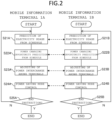
FIG. 2 is a process flow diagram of power management in Example 1. -
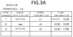
FIG. 3A is an example for a usage schedule ofmobile information terminal 1A in Example 1. -
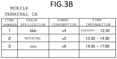
FIG. 3B is an example for a usage schedule ofmobile information terminal 1B in Example 1. -
FIG. 3C is an example for a usage schedule ofmobile information terminal 1C in Example 1. -
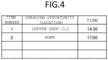
FIG. 4 is an example schedule for power charging opportunity prediction in Example 1. -
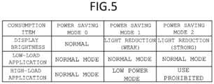
FIG. 5 is a diagram illustrating the power saving mode of the mobile information terminal in Example 1. -
FIG. 6 is an example of the remaining battery capacity prediction at a power charging opportunity in Example 1. -
FIG. 7A is an example of power saving mode settings when for each mobile information terminal of the remaining battery capacity prediction is small in Example 1. -
FIG. 7B is an example of power saving mode settings when for each mobile information terminal of the remaining battery capacity prediction is large in Example 1. -
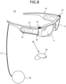
FIG. 8 is an example for the external appearance configuration of an HMD as an example for a mobile information terminal in Example 1. -
FIG. 9 is an example for the functional block configuration of a mobile information terminal (HMD) in Example 1. -
FIG. 10A is a diagram, the setting lower limit value of the remaining battery capacity is changed according to the predicted arrival time in Example 2. -
FIG. 10B is a diagram, the setting lower limit value of the remaining battery capacity is changed according to the predicted charging time in Example 2. -
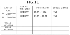
FIG. 11 is an example for power usage result of the user in Example 3. -
FIG. 12 is an example for action history of the user in Example 4. -
FIG. 13 is a process flow diagram of power management in Example 5. -
FIG. 14A is diagram, the threshold for power saving mode switching is changed according to the predicted arrival time in Example 5. -
FIG. 14B is diagram, the threshold for power saving mode switching is changed according to the predicted charging time in Example 5. -
FIG. 15 is a process flow diagram of power management in Example 6. -
FIG. 16 is an example for the display of a charging spot of the mobile information terminal that is the HMD in Example 6. - Hereinafter, an embodiment of the present invention will be described by using drawings.
-
Figure 1 is a system configuration diagram of power management for a group of mobile information terminals in this example. InFigure 1 , the system configuration of power management for a group of mobile information terminals has at least one, as mobile information terminal, for example, amobile information terminal 1A that is HMD (Head Mounted Display), amobile information terminal 1B that is smartphone, or amobile information terminal 1C that is smartwatch. The processing operations of the following mobile information terminals may be performed by these terminals alone or in conjunction with each other. In the following descriptions,mobile information terminals 1A through 1C are collectively referred to asmobile information terminals 1. Mobile information terminal may also be described simply as mobile terminals or terminals. - The system configuration may also include a
mobile battery 2 that interchanges power to the mobile information terminal. Themobile battery 2 communicates with themobile information terminal 1, provides the information necessary to manage the power management system, and interchanges the power it holds to the mobile information terminal. -
Server 3 performs processing on behalf of eachmobile information terminal 1, mediates the transmission and reception of information between eachmobile information terminal 1, and provides necessary information, via a communication network 9. Theserver 3 may be, for example, a local server, a cloud server, an edge server, a net service, or any other form. Theserver 3 may also process portion of the functions of themobile information terminal 1. -
Figure 2 is a process flow diagram of power management in this example. InFigure 2 , for example, themobile information terminal 1A is an HMD and themobile information terminal 1B is a smartphone. It is also assumed that, prior to this process flow, communication between eachmobile information terminal 1 has been established, and the remaining battery capacity is known for each. Amobile battery 2 can also be regarded as a special mobile information terminal whose main function is to interchange power to other mobile information terminals, so it is basically controlled by this flow. However, in the case of amobile battery 2, the power used by itself is only the power related to battery control, and basically no power saving is performed. However, power saving may be performed if it is possible to save power within a range that does not affect battery control, such as when especially there is an indicator that displays the status. - In
Figure 2 , in first steps S21A and S21B, prediction of electricity usage is performed from user schedules. Thus, prediction of electricity usage is performed from such as scheduled use of application software (hereinafter abbreviated as "apps"), based on normal usage patterns, viewing reservations. In addition, one mobile information terminal may assist another mobile information terminal in overall information processing, such as when there are differences in information processing capabilities among mobile information terminals, or when schedules are managed centrally. - For example,
Figures 3A ,3B, and 3B are examples of usage schedules of eachmobile information terminal 1.Figures 3A ,3B , and3C show the usage application, power consumption, and time information, respectively, as a usage schedule of applications with a high load on themobile information terminal - Next, returning to
Figure 2 , steps S22A and S22B are performed power charging opportunity prediction from the user schedule.Figure 4 shows an example of a schedule for power charging opportunity prediction. InFigure 4 , as the user's schedule, shows the opportunities to charge, thus, the locations where charging is to take place and the times to go there. From the user's schedule like this, the opportunities available for charging are predicted. In addition, since this power charging opportunity prediction is common regardless of the mobile information terminal, it is shared among mobile information terminals. - Next, in steps S23A and S23B, power interchange among mobile information terminals is adjusted. That is, assuming the highest degree of power saving mode, at the next charging opportunity, determining whether it can be covered by interchanging power of other mobile information terminals to the mobile information terminal whose remaining battery capacity falls below the setting lower limit value, and notifying to the user. At this time, the efficiency of charging among mobile information terminals is also taken into consideration. In addition, when it cannot be relief by the power interchange, it is notified to user that to select stop using the application, farther, stop using the mobile information terminal. Note that, since loss is generated by the power interchange, the power interchange may be performed automatically, but it is preferable to perform it by the user's instruction. However, in the case of power interchange from the
mobile battery 2, it is preferable that the interchanging be performed automatically, since this is the primary function of themobile battery 2. If power interchange is not performed, power management should be performed for each individual terminal. -
Figure 5 is a diagram illustrates the power saving modes of the mobile information terminal. InFigure 5 , the relationship between consumption items that consume power andpower saving modes power saving modes Power saving mode 0 is a state of no power saving, and the higher the number, the higher the power saving level, and the greater the reduction in power consumption. In other words, a higher power saving mode enhances power saving, while a lower power saving mode relaxes power saving. Specifically, inFigure 5 , for the consumption items display brightness, low-load applications, and high-load applications,power saving mode 0 shall be set to normal mode,power saving mode 1 shall be set to weak light reduction, normal mode, and low power mode, respectively, andpower saving mode 2 shall be set to strong light reduction, normal mode, and use prohibited, respectively. Thus, low-load applications such as e-mail should be used in normal mode as much as possible, and high-load applications with large unnecessary power consumption should be used in low-power mode inpower saving mode 1 and disabled inpower saving mode 2. - Next, returning to
Figure 2 , in steps S24A and S24B, the remaining battery capacity at the next charging opportunity is predicted, from the prediction of electricity usage and the power charging opportunity prediction. -
Figure 6 shows an example of remaining battery capacity prediction at a certain charging opportunity.Figure 6 shows the remaining battery capacity prediction for each mobile information terminal, the amount of possible to power interchange, and the destination of interchange, at the charging opportunity (location) at the coffee shop △△ in the charging opportunity schedule table inFigure 4 . InFigure 6 , show that inmobile information terminal 1A, remaining battery capacity be negative by the time it gets to the coffee shop △ △, inmobile information terminals mobile information terminal 1A. - Then, based on this remaining battery capacity prediction, the power saving mode is determined until the next charging opportunity. For example, if the remaining battery capacity prediction is below the setting lower limit value, the power saving mode is increased.
-
Figures 7A and7B are examples of power saving mode settings for each mobile information terminal at a given point in time.Figure 7A is a case where the remaining battery power prediction is small and an overall strict power saving mode is set. InFigure 7A , the power saving mode atmobile information terminal 1A (HMD) is set low and loose, considering the priority among them.Figure 7B is an example of power saving mode setting when the remaining battery capacity prediction has a large and has margin. InFigure 7B , all mobile information terminals are in normal mode (i.e., power saving mode 0). - Note that, if it is predicted that the operation of all mobile information terminals can be maintained until the next charging opportunity by power interchange, the power saving mode of some or all mobile information terminals should be set to a lower level within the range where operation can be maintained, considering the priority. Also, the power saving mode to be set will also be changed as needed because the above remaining battery capacity prediction will change over time due to the difference the predicted value of electricity usage.
- Next, returning to
Figure 2 , in steps S25A and S25B, until an end instruction is received, the power management process is repeated with returns to steps S21A and S21B, and when end instruction is received, the power management process end. - Although
Figure 2 shows an example for case of two mobile information terminals, the same control applies to three or more. The mobile information terminal that receives an end instruction finishes the power management process, but the power management process continues among the other mobile information terminals that have not received an end instruction. Also, even if only one terminal is left, the process of power management can still be carried out, except for power interchange. - In the above description of control, the power saving mode setting was performed based on a predetermined time called a schedule, but if a deviation from that time is expected in an actual situation, the power saving mode setting is dynamically modified to match each expected time. This dynamic modification can be applied in other examples as well.
-
Figure 8 is an example of the external configuration of an HMD as an example of a mobile information terminal in this example. InFigure 8 , themobile information terminal 1A, which is an HMD, has a display including adisplay surface 11 in a glasses-like housing 10. This display is, for example, a transmissive display, in which a real image of the outside world is transmitted through thedisplay surface 11 and an image is superimposed on the real image. Thehousing 10 is mounted with a controller, acamera 12, adistance measurement sensor 13, andother sensors 14 etc. - The
camera 12 are, for example, two cameras located on the left and right sides of thehousing 10, which capture an area including the front of the HMD and acquire images. Thedistance measurement sensor 13 is a sensor that measures the distance between the HMD and an object in the outside world. Thedistance measurement sensor 13 may use a TOF (Time Of Flight) type sensor, a stereo camera, or any other type. Thesensor 14 include a group of sensors for detecting the position and orientation status of the HMD. The left and right sides of thehousing 10 are equipped withaudio input device 18 including microphones andaudio output device 19 including speakers and earphone jacks. - A
mobile information terminal 1A that is an HMD may be attached to anoperation apparatus 20 such as a remote controller. In such a case, the HMD performs, for example, short-range wireless communication, with itsoperation apparatus 20. The user can input instructions regarding the functions of the HMD, move the cursor on thedisplay surface 11, and the like, by operating theoperation apparatus 20 with his/her hand. The HMD may communicate and cooperate with an external smartphone, PC, etc. For example, the HMD may receive AR (Augmented Reality) image data from a smartphone application. - A
mobile information terminal 1A that is an HMD may display virtual images, such as AR, on itsdisplay surface 11. For example, amobile information terminal 1A that is an HMD generates virtual images to guide the user and display them on thedisplay surface 11. - In addition, the
mobile information terminal 1A is equipped with a chargingcable 21 and acharger 22. Thecharger 22 includes an antenna for wireless charging. Themobile information terminal 1A may be the power supply side or the power receiving side. Nore that, the charger may be incorporated into thehousing 10, in which case the chargingcable 21 is omitted. Also, the chargingcable 21 may have a structure that is attach/detach for thehousing 10. Furthermore, power may be received and transferred to and from other terminals by wire instead of wireless power transfer. In such a case, thecharger 22 shall be read as a connector. -
Figure 9 is an example of the functional block configuration of themobile information terminal 1A, the HMD ofFigure 8 . Basically, othermobile information terminals 1 have the same configuration. Themobile information terminal 1 includes, such as, aprocessor 101,memory 102,camera 12,distance measurement sensor 13,sensor 14,display 103,communication interface 104,audio input device 18 including microphone,audio output device 19 including speaker, etc.,wireless transmission interface 105,wireless receiving interface 106,operation inputter 107,battery 108, andcharge controller 109. These elements are interconnected through buses, etc. - The
processor 101 consists of a CPU, ROM, RAM, etc., and constitutes the controller of the HMD. Theprocessor 101 executes processing according to thecontrol programs 31 and / orapplication programs 32 inmemory 102 to realize the function, such as, OS, middleware, applications, and other functions.Memory 102 is a memory apparatus and consists of nonvolatile storage devices, etc., and stores various data and information handled by theprocessor 101 and, etc. Thememory 102 also stores images and detection information, etc., acquired by thecamera 12, etc., as temporary information. - A
camera 12 acquires an image by converting light incident through the lens into an electrical signal at the image sensor. When such as a TOF (Time Of Flight) sensor is used, thedistance measurement sensor 13 calculates the distance to an object from the time it takes for light emitted into the outside world to hit the object and return.Sensor 14 includes, for example,acceleration sensor 141, gyro sensor (angular rate sensor) 142,geomagnetic sensor 143, andGPS receiver 144. Thesensor 14 detects the position, orientation, motion, and other states of the HMD using the detection information from these sensors . Note that, not limited to this, the HMD may be equipped with, illumination sensor, proximity sensor, barometric pressure sensor, and the like. Thedistance measurement sensor 13 and thesensor 14 may not be separate, but thedistance measurement sensor 13 may be one of thesensors 14. - A
display 103 includes a display drive circuit and adisplay surface 11 and displays a virtual image or other image on thedisplay surface 11 based on image data ofdisplay information 34. Note that, thedisplay 103 is not limited to a transmissive display but may be a non-transmissive display or the like. - The
communication interface 104 includes communication processing circuitry for various predetermined communication interfaces, antennas, and other components. Examples of communication interfaces give mobile network, Wi-Fi (registered trademark), Bluetooth (registered trademark), UWB (Ultra Wide Band), infrared, etc. Thecommunication interface 104 performs wireless communication processing, etc. with othermobile information terminals 1 and access points. Also, thecommunication interface 104 also performs short-range communication processing with theoperation apparatus 20. - The
wireless transmission interface 105 transmits a wireless signal from a radio wave source accompanied by an identification signal used for position estimation. Here, the wireless signal accompanied by the identification information is, for example, a UWB, Bluetooth, or other signal. Thewireless receiving interface 106 receives the wireless signal of the radio wave source accompanied by the above-mentioned identification signal and measures the reception strength, signal timing, etc. Note that, the positional relationship between mobile information terminals may be used as an aid in determining the availability of wireless power supply. Awireless transmission interface 105 and awireless receiving interface 106 may also be used for information communication. When mobile information terminals that only transmit or receive wireless signals, the necessary devices may be comprised. - The
audio input device 18 converts input audio from a microphone into audio data. Theaudio output device 19 outputs audio from a speaker or the like based on the audio data. The audio input device may be equipped with an audio recognition function. The audio output device may be equipped with an audio synthesis function. Theoperation inputter 107 is a part that accepts operation input to the HMD, e.g., power on/off, volume adjustment, etc., and is configured of hardware buttons, touch sensors, etc. Thebattery 108 is a secondary battery and supplies power to various parts of themobile information terminal 1. - A controller by the
processor 101, has acommunication control unit 101A,display control unit 101B, data processing unit 101C, anddata acquisition unit 101D, as examples of functional block configurations realized by processing. - The
memory 102 stores controlprogram 31,application program 32, settinginformation 33,display information 34,power management information 35, etc. Thecontrol program 31 is a program to realize power management of themobile information terminal 1.Application program 32 are various programs used by users. Settinginformation 33 includes system setting information and user setting information related to each function.Display information 34 includes image data for displaying virtual images on thedisplay surface 11 and position coordinate information.Power management information 35 is information related to the remaining battery capacity of the own terminal and other terminals, estimated power usage, charging opportunities, and power saving mode, for performing power management. - The
communication control unit 101A controls communication processing using thecommunication interface 104, such as when communicating with othermobile information terminals 1. Thedisplay control unit 101B controls the display of virtual images, etc. on thedisplay surface 11 of thedisplay 103 usingdisplay information 34. - The data processing unit 101C reads and writes
power management information 35, predicts the remaining battery capacity of its own and other terminals, predicts charging opportunities, sets power saving modes, etc. This processing may be performed at each terminal or at the representative terminal. Thedata acquisition unit 101D acquires data on the remaining battery capacity of its own terminal and information on other terminals, etc. - The
mobile battery 2 configuration is the configuration that leaving the configuration necessary to control thebattery 108 from the configuration inFigure 9 and restricting the functions as appropriate. - As described above, according to this example, the power saving mode of the mobile information terminal is controlled by the mobile information terminal based on the predicting of the future usage of the mobile information terminal and the power charging opportunity prediction, so that the remaining battery capacity of the secondary battery can be effectively used, and a mobile information terminal with high user convenience and its control method can be provided.
- In this embodiment, the point where the setting lower limit value of the remaining battery capacity, which is the criterion for determining power saving mode switching and power interchange, is variable is explained.
-
Figures 10A and10B illustrate the setting lower limit value of remaining battery capacity in this example. InFigure 10A , the setting lower limit value of the remaining battery capacity is changed according to the predicted arrival time to the charging opportunity (location) . This is because the longer the arrival time to the charging opportunity, the larger the prediction error of the remaining battery capacity, and the greater the risk of running out of battery. Specifically, inFigure 10A , the setting lower limit values are, respectively, set to 30%, 20%, and 10% of full charge, when the predicted time to reach is 2 hours or more, 1 to 2 hours, and less than 1 hour. - Furthermore, at the charging opportunity, the above setting lower limit value may be changed depending on the predicted time that can be charged, that is, the predicted time that can be allocated for charging. Shown in
Figure 10B is a correction coefficient that is multiplied by the setting lower limit value shown inFigure 10A . It shows the case where the shorter the time available for charging, the larger the setting lower limit value. This is because if the time available for charging is short, the battery cannot be charged sufficiently, and the risk of run out battery after charging increases. - The setting methods are not limited to those shown in the figure, but can be varied. It may also be different for each mobile information terminal. Furthermore, when the charging opportunity is at home, the risk is lower than in the case of other charging opportunities, so the setting lower limit value may be set exceptionally low.
- As described above, in addition to the effects of Example 1, this example provides a mobile information terminal and its control method that can reduce the possibility of running out of battery more and also does not take up too much of the remaining battery margin.
- In Example 1, performs the prediction of electricity usage from user schedules. In contrast, this example describes a point in which prediction of electricity usage may be performed by considering the power usage result of the user.
-
Figure 11 is an example of the power usage result of the user in this embodiment. InFigure 11 , the average power usage result by action, day of the week, and timeframe is described. These user usage results may be considered for prediction of electricity usage. User behavior is estimated by inspecting camera information and HMD movements. Non-habitual power use is taken into account in the power usage prediction by reading from the schedule book the records of scheduled power consumption of the terminal, such as viewing reservations. - As described above, this example allows more accurate power usage prediction to be implemented in addition to the effects of Example 1.
- In Example 1, power charging opportunity prediction was performed from the user schedule. In contrast, this example describes a point where power charging opportunity prediction can be performed from action history of the user.
-
Figure 12 is an example of the action history of the user in this embodiment. InFigure 12 , the location, day of the week, time, and charging time are noted. These, the action history of the user, may be taken into account for power charging opportunity prediction. - Note that, if charging at a certain location is a patterned behavior, the charging opportunity shall be based on the record. If the behavior is not habitual, then the charging opportunity shall be based on reading the schedule of activities from the schedule book and looking for a place where charging is possible.
- As described above, this example allows more accurate power charging opportunity prediction to be implemented in addition to the effects of Example 1.
- In this example, power management is performed using only power charging opportunity prediction, not prediction of electricity usage.
-
Figure 13 is a process flow diagram of power management in this example. InFig. 13 , the same configuration as inFig. 2 is marked with the same symbol and its description is omitted. InFig. 13 , the difference fromFig. 2 is that steps S21A and S21B of prediction of electricity usage from user schedules are omitted. - In
Figure 13 , in steps S24A and S24B of the power saving mode control, change to the value of the remaining battery capacity that switch the power saving mode, and switch the power saving mode by the time until reach the charging opportunity. Note that, in order to avoid as strict a power saving mode as possible, power may be interchanged from terminals that can afford it. -
Figures 14A and14B illustrate the threshold for power saving mode switching in this example. InFigure 14A , the threshold for power saving mode switching is changed according to the predicted arrival time to the charging opportunity. The first threshold is the threshold for switching frompower saving mode 0 topower saving mode 1. The second threshold is the threshold for switching frompower saving mode 1 topower saving mode 2. This is because the longer the arrival time to the charging opportunity, the greater the prediction error of the remaining battery capacity and the greater the risk of running out of battery. Specifically, inFigure 14A , the first threshold is set to 30%, 20%, and 15% of full charge, and the second threshold is set to 15%, 10%, and 10% of full charge for cases where the predicted time to reach the point is more than 2 hours, 1 to 2 hours, and less than 1 hour, respectively. - Furthermore, in the charging opportunity, the above first and second thresholds may be varied depending on the predicted time that can be charged, that is, the predicted time allocated for charging. Shown in
Figure 14B are the correction coefficients that are multiplied by the first and second thresholds shown inFigure 14A . It shows the case where the shorter the time available for charging, the larger the first and second thresholds. This is because if the time available for charging is short, the battery cannot be charged sufficiently, and the risk of run out battery after charging increases. Note that, the setting method is not limited to this. - As described above, this example provides a mobile information terminal and its control method for high user convenience by enabling effective use of the remaining battery capacity of the secondary battery by allowing the mobile information terminal to control the power saving mode of the mobile information terminal based on the power charging opportunity prediction of the mobile information terminal.
- This example describes the process when charging is necessary even if the power saving mode is switched by the power saving mode control described in Example 1-5.
-
Figure 15 is a process flow diagram of power management in this example. InFigure 15 , step S61 is the process of switching the power saving mode by the power saving mode control described in Example 1-5. Then, in step S62, for example, the power saving mode is at maximum and a determination is made as to whether charging is necessary based on the power usage. For example, a threshold value for the remaining battery capacity is set, and if the battery capacity falls below the threshold value, it is determined that charging is necessary. And, if charging is necessary, charging spots are searched and recommending them to the user, in step S63. The search is conducted by searching for information on the Internet or by using cameras or beacons to search for charging spots in the surrounding area. In step S64, the process returns to step S61 and repeats the power management process, until an end instruction is received, and the power management process is end by receiving the end instruction. -
Figure 16 is an example of the display of a charging spot for amobile information terminal 1A, which is the HMD in this embodiment. InFigure 16 , the outer frame represents the user's field of view when the HMD is optical see-through, and the field of view of the display when the HMD is video see-through. - As shown in
Figure 16 , the chargingspot 61 is an AR object and is superimposed on an image of the outside world. The current remaining battery capacity and the predicted remaining battery capacity may also be displayed for eachmobile information terminal - As described above, this example provides a mobile information terminal and its control method that is highly convenient for the user because it can search for charging spots and recommend them to the user when charging is necessary.
- The above examples have been described, and the invention will contribute to the realization of the SDGs (Sustainable Development Goals), especially item 7 energy.
- The above examples, for the invention in an easy to understand, are described in detail to explain and are not necessarily limited to those with all the described configurations. For example, the programs described in each processing example may be independent programs, or multiple programs may constitute a single application program. In addition, the order in which each process is performed may be interchanged for execution. The functions, etc. of this example described above are described as being realized in software by the CPU executing an operation program that realizes the respective functions, etc. However, some or all of them may be realized in hardware by, for example, designing them in an integrated circuit. In addition, part or all of each function may be realized by a server. Programs that realize each function, tables, files, and other information may be stored in memory, hard disks, SSD (Solid State Drives), or other recording media, IC cards, SD cards, DVDs, or other recording media, or may be stored in devices on a communication network. It is also possible to replace part of the configuration of one example with the configuration of another example, and it is also possible to add the configuration of another example to the configuration of one example. In addition, relating to the portion of configuration of each example, it is possible to add, delete, or replace other configurations.
-
- 1, 1A~1C
- mobile information terminal
- 2
- mobile battery
- 3
- server
- 9
- communication network
- 10
- housing
- 11
- display surface
- 35
- power management information
- 101
- processor
- 101C
- data processing unit
- 101D
- data acquisition unit
- 102
- memory
- 103
- display
- 107
- operation inputter
- 108
- battery
- 109
- charge controller
- 61
- charging spot
Claims (15)
- A mobile information terminal (1) includes a second battery (108), a controller (101), and a memory apparatus (102), wherein
the controller (101) performs prediction of electricity usage and power charging opportunity prediction from schedule be memorized in the memory apparatus (102), and sets power saving mode with different power saving level to reduce power consumption, based on the prediction of electricity usage and the power charging opportunity prediction. - The mobile information terminal (1) according to claim 1, wherein
if each time on the schedule is expected to deviate from actual usage, the power saving mode setting is dynamically modified based on the expected time. - The mobile information terminal (1) according to claim 1, wherein
the mobile information terminal (1) predicts the remaining battery capacity of the second battery (108) at the next charging opportunity from the prediction of electricity usage and power charging opportunity prediction, and changes the power saving mode so that the power saving level becomes higher if the remaining battery capacity prediction falls below a setting lower limit value. - The mobile information terminal (1) according to claim 1, whereinthe prediction of electricity usage performs prediction from the viewing reservation and/or the scheduled use of application software with high load, andthe power charging opportunity prediction performs prediction that the opportunity to charge and the chargeable opportunity from the time of go there.
- The mobile information terminal (1) according to claim 1, wherein
if battery capacity of the second battery (108) falls below the setting lower limit value at the next charging opportunity, the controller (101) determines whether the power can be covered by power interchange from other mobile information terminals or mobile batteries. - The mobile information terminal (1) according to claim 3, wherein
the mobile information terminal (1) changes the setting lower limit value according to the predicted arrival time to the charging opportunity, and the longer the predicted arrival time to the charging opportunity, performs to larger the setting lower limit value. - The mobile information terminal (1) according to claim 6, wherein
the mobile information terminal (1) changes the setting lower limit value according to the predicted time that can be charged at the charging opportunity, the shorter the predicted time that can be charged, performs to the larger the setting lower limit value. - The mobile information terminal (1) according to claim 1, wherein
the prediction of electricity usage is performed by considering the power usage result of the user. - The mobile information terminal (1) according to claim 1, wherein
the power charging opportunity prediction is performed by considering the electric action history of the user. - A mobile information terminal (1) includes a second battery (108), a controller (101), and a memory apparatus (102), wherein
the controller (101) performs prediction of charging opportunity from schedule be memorized in the memory apparatus (102), and sets power saving mode with different power saving level to reduce power consumption, based on the time until reach the charging opportunity. - The mobile information terminal (1) according to claim 10, wherein
the longer the arrival time to the charging opportunity, the larger the threshold value for switching to the power saving mode. - The mobile information terminal (1) according to claim 11, wherein
the threshold value is changed according to the predicted time that can be charged at the charging opportunity, and the shorter the predicted time that can be charged, the larger the threshold value is. - The mobile information terminal (1) according to claim 1, wherein
the controller (101) searches for charging spots and notifies the user when the set power saving mode is at the maximum power saving level and the secondary battery needs to be charged. - The mobile information terminal (1) according to claim 13, comprising:a display (103), whereinthe mobile information terminal (1) displays the charging spot on the display (103) superimposed on the external image.
- A control method for a mobile information terminal (1) that supplies power by a secondary battery (108), whereinperforming prediction of electricity usage and power charging opportunity prediction from usage schedule,setting power saving mode with different power saving level to reduce power consumption of the secondary battery (108), based on the prediction of electricity usage and the power charging opportunity prediction.
Applications Claiming Priority (1)
| Application Number | Priority Date | Filing Date | Title |
|---|---|---|---|
| PCT/JP2021/030684 WO2023021709A1 (en) | 2021-08-20 | 2021-08-20 | Mobile information terminal and method for controlling same |
Publications (2)
| Publication Number | Publication Date |
|---|---|
| EP4391507A1 true EP4391507A1 (en) | 2024-06-26 |
| EP4391507A4 EP4391507A4 (en) | 2025-05-28 |
Family
ID=85240394
Family Applications (1)
| Application Number | Title | Priority Date | Filing Date |
|---|---|---|---|
| EP21954275.0A Pending EP4391507A4 (en) | 2021-08-20 | 2021-08-20 | Mobile information terminal and method for controlling same |
Country Status (5)
| Country | Link |
|---|---|
| US (1) | US20250370530A1 (en) |
| EP (1) | EP4391507A4 (en) |
| JP (1) | JP7631531B2 (en) |
| CN (1) | CN117813809A (en) |
| WO (1) | WO2023021709A1 (en) |
Families Citing this family (1)
| Publication number | Priority date | Publication date | Assignee | Title |
|---|---|---|---|---|
| WO2026105186A1 (en) * | 2024-11-12 | 2026-05-21 | 株式会社ソニー・インタラクティブエンタテインメント | Display control system, display control method, and program |
Family Cites Families (30)
| Publication number | Priority date | Publication date | Assignee | Title |
|---|---|---|---|---|
| US8041967B2 (en) * | 2005-02-15 | 2011-10-18 | Hewlett-Packard Development Company, L.P. | System and method for controlling power to resources based on historical utilization data |
| JP5231869B2 (en) | 2007-07-02 | 2013-07-10 | パナソニック株式会社 | Information processing device |
| US8156363B2 (en) * | 2007-07-02 | 2012-04-10 | Panasonic Corporation | Information processing device and mobile phone including comparison of power consumption information and remaining power |
| JP4881447B2 (en) * | 2010-01-29 | 2012-02-22 | 株式会社東芝 | Electronic device and audio signal amplification method |
| JP5260706B2 (en) * | 2011-06-24 | 2013-08-14 | レノボ・シンガポール・プライベート・リミテッド | Power system for portable electronic equipment with timekeeping circuit |
| KR101844283B1 (en) * | 2011-08-18 | 2018-04-03 | 삼성전자주식회사 | A method and an apparatus for energy sharing of wireless communication device |
| KR101825854B1 (en) * | 2013-11-27 | 2018-03-22 | 인텔 코포레이션 | Contextual power management |
| US9442548B1 (en) * | 2014-03-18 | 2016-09-13 | Amazon Technologies, Inc. | Device charging system |
| US9939868B2 (en) * | 2014-05-12 | 2018-04-10 | Gary Stephen Shuster | Device power and resource management |
| US9361091B2 (en) * | 2014-05-27 | 2016-06-07 | Nintendo Co., Ltd. | Information processing apparatus, information processing system, information processing method, and non-transitory computer-readable storage medium having stored therein an information processing program |
| CN114115461B (en) * | 2014-08-06 | 2024-04-26 | 苹果公司 | Reduced size user interface for battery management |
| JP2017050655A (en) | 2015-08-31 | 2017-03-09 | シャープ株式会社 | Information processing apparatus, information processing apparatus control method, control program, and recording medium |
| US10283985B2 (en) * | 2016-05-25 | 2019-05-07 | Lenovo (Singapore) Pte. Ltd. | Systems and methods to determine time at which battery is to be charged |
| US10114440B2 (en) * | 2016-06-22 | 2018-10-30 | Razer (Asia-Pacific) Pte. Ltd. | Applying power management based on a target time |
| US9924464B2 (en) * | 2016-07-27 | 2018-03-20 | Motorola Mobility Llc | Identifying at least one alternate power source for providing power to a portable electronic device |
| JP2018038140A (en) * | 2016-08-30 | 2018-03-08 | シャープ株式会社 | Power management system, power management device, and power management method |
| US20180082570A1 (en) * | 2016-09-20 | 2018-03-22 | Qualcomm Incorporated | Dynamic battery charging threshold for mobile devices |
| US20180145514A1 (en) * | 2016-11-21 | 2018-05-24 | Microsoft Technology Licensing, Llc | Predictive battery charge and discharge analysis |
| US10452123B2 (en) * | 2017-03-30 | 2019-10-22 | Google Llc | Predictive power saving and screen dimming for computing devices |
| US10760913B2 (en) * | 2018-02-21 | 2020-09-01 | Motorola Solutions, Inc. | Determining and reducing inertial navigation system drift |
| KR20210092223A (en) * | 2018-11-07 | 2021-07-23 | 아로에 리미티드 | smart charging system |
| WO2020100288A1 (en) * | 2018-11-16 | 2020-05-22 | 住友電気工業株式会社 | Charging assistance system, method, and computer program |
| US20220006295A1 (en) * | 2018-11-23 | 2022-01-06 | Aurora's Grid Sàrl | A Method And System For Ageing-Aware Management Of The Charging And Discharging Of Li-Ions Batteries |
| EP3664248B1 (en) * | 2018-12-06 | 2021-03-03 | GN Audio A/S | Communication apparatus with charging reminder, and method |
| KR102748889B1 (en) * | 2019-02-18 | 2025-01-02 | 삼성전자주식회사 | Electronic device for adaptive power management |
| WO2021231454A1 (en) * | 2020-05-13 | 2021-11-18 | Rearden Power LLC | Hybrid battery management system |
| US11598810B2 (en) * | 2020-09-24 | 2023-03-07 | Dell Products L.P. | Battery runtime forecasting for an information handling system |
| TWI781453B (en) * | 2020-09-30 | 2022-10-21 | 財團法人資訊工業策進會 | Energy dispatch system, apparatus, and method |
| US11840157B2 (en) * | 2021-07-19 | 2023-12-12 | Rivian Ip Holdings, Llc | Charge time estimation |
| US11886270B2 (en) * | 2021-09-24 | 2024-01-30 | Apple Inc. | Power-efficient dynamic application content display for electronic devices |
-
2021
- 2021-08-20 WO PCT/JP2021/030684 patent/WO2023021709A1/en not_active Ceased
- 2021-08-20 EP EP21954275.0A patent/EP4391507A4/en active Pending
- 2021-08-20 CN CN202180101557.2A patent/CN117813809A/en active Pending
- 2021-08-20 US US18/684,638 patent/US20250370530A1/en active Pending
- 2021-08-20 JP JP2023542173A patent/JP7631531B2/en active Active
Also Published As
| Publication number | Publication date |
|---|---|
| WO2023021709A1 (en) | 2023-02-23 |
| EP4391507A4 (en) | 2025-05-28 |
| US20250370530A1 (en) | 2025-12-04 |
| JPWO2023021709A1 (en) | 2023-02-23 |
| CN117813809A (en) | 2024-04-02 |
| JP7631531B2 (en) | 2025-02-18 |
Similar Documents
| Publication | Publication Date | Title |
|---|---|---|
| EP3652612B1 (en) | Method and electronic device for providing mode switching and storage medium thereof | |
| US10782773B2 (en) | Electronic device with power management | |
| US20240146356A1 (en) | Electronic Device With Activity-Based Power Management | |
| JP6567768B2 (en) | Wireless communication radio management with emphasis on power consumption | |
| US8793520B2 (en) | Power management of electronic devices based on charging location | |
| US12463438B2 (en) | Wearable electronic device including multiple batteries and method for operating the same | |
| CN106469928A (en) | Electronic device and method of wired and wireless charging in electronic device | |
| CN108475933A (en) | Electronic device and method of operation thereof | |
| KR20170105795A (en) | Electronic device and operating method thereof | |
| US11695291B2 (en) | Method to charge battery and electronic device including battery | |
| US20260128615A1 (en) | Power management system for an input device | |
| KR20180104987A (en) | Electronic apparatus and method for charging battery | |
| KR20190090474A (en) | Electronic device comprising battery and method for controlling charging thereof | |
| CN113767546B (en) | Electronic device including a plurality of batteries | |
| CN111464690B (en) | Application preloading method, electronic device, chip system and readable storage medium | |
| WO2021017823A1 (en) | Charging method, electronic device and storage medium | |
| CN118762649A (en) | Display screen compensation method, device, equipment and storage medium | |
| CN116868475A (en) | battery management system | |
| US20250370530A1 (en) | A mobile information terminal and a control method thereof | |
| US12001620B2 (en) | Wireless charging for an input device | |
| CN117458661A (en) | Charging control methods and devices, equipment and storage media | |
| CN117707323A (en) | Control method of duration, electronic equipment and readable storage medium | |
| KR101728965B1 (en) | Mobile terminal | |
| CN221726316U (en) | Integrated intelligent glasses based on somatosensory operation | |
| CN120714181A (en) | Fire fighting method, device and energy storage system for energy storage system |
Legal Events
| Date | Code | Title | Description |
|---|---|---|---|
| STAA | Information on the status of an ep patent application or granted ep patent |
Free format text: STATUS: THE INTERNATIONAL PUBLICATION HAS BEEN MADE |
|
| PUAI | Public reference made under article 153(3) epc to a published international application that has entered the european phase |
Free format text: ORIGINAL CODE: 0009012 |
|
| STAA | Information on the status of an ep patent application or granted ep patent |
Free format text: STATUS: REQUEST FOR EXAMINATION WAS MADE |
|
| 17P | Request for examination filed |
Effective date: 20240219 |
|
| AK | Designated contracting states |
Kind code of ref document: A1 Designated state(s): AL AT BE BG CH CY CZ DE DK EE ES FI FR GB GR HR HU IE IS IT LI LT LU LV MC MK MT NL NO PL PT RO RS SE SI SK SM TR |
|
| DAV | Request for validation of the european patent (deleted) | ||
| DAX | Request for extension of the european patent (deleted) | ||
| REG | Reference to a national code |
Ref country code: DE Ref legal event code: R079 Free format text: PREVIOUS MAIN CLASS: H04M0001720000 Ipc: G06F0001321200 |
|
| A4 | Supplementary search report drawn up and despatched |
Effective date: 20250430 |
|
| RIC1 | Information provided on ipc code assigned before grant |
Ipc: H04M 1/05 20060101ALI20250424BHEP Ipc: H04W 52/02 20090101ALI20250424BHEP Ipc: H04M 1/72 20210101ALI20250424BHEP Ipc: H04M 1/72451 20210101ALI20250424BHEP Ipc: G06F 3/01 20060101ALI20250424BHEP Ipc: G06F 1/3234 20190101ALI20250424BHEP Ipc: G06F 1/16 20060101ALI20250424BHEP Ipc: G06F 1/3212 20190101AFI20250424BHEP |