EP4391396A1 - Wireless communication apparatus - Google Patents
Wireless communication apparatus Download PDFInfo
- Publication number
- EP4391396A1 EP4391396A1 EP22858684.8A EP22858684A EP4391396A1 EP 4391396 A1 EP4391396 A1 EP 4391396A1 EP 22858684 A EP22858684 A EP 22858684A EP 4391396 A1 EP4391396 A1 EP 4391396A1
- Authority
- EP
- European Patent Office
- Prior art keywords
- wireless communication
- communication apparatus
- cover portion
- heat dissipation
- disposed
- Prior art date
- Legal status (The legal status is an assumption and is not a legal conclusion. Google has not performed a legal analysis and makes no representation as to the accuracy of the status listed.)
- Pending
Links
Images


Classifications
-
- H—ELECTRICITY
- H04—ELECTRIC COMMUNICATION TECHNIQUE
- H04B—TRANSMISSION
- H04B1/00—Details of transmission systems, not covered by a single one of groups H04B3/00 - H04B13/00; Details of transmission systems not characterised by the medium used for transmission
- H04B1/38—Transceivers, i.e. devices in which transmitter and receiver form a structural unit and in which at least one part is used for functions of transmitting and receiving
-
- H—ELECTRICITY
- H05—ELECTRIC TECHNIQUES NOT OTHERWISE PROVIDED FOR
- H05K—PRINTED CIRCUITS; CASINGS OR CONSTRUCTIONAL DETAILS OF ELECTRIC APPARATUS; MANUFACTURE OF ASSEMBLAGES OF ELECTRICAL COMPONENTS
- H05K7/00—Constructional details common to different types of electric apparatus
- H05K7/20—Modifications to facilitate cooling, ventilating, or heating
- H05K7/2039—Modifications to facilitate cooling, ventilating, or heating characterised by the heat transfer by conduction from the heat generating element to a dissipating body
-
- H—ELECTRICITY
- H01—ELECTRIC ELEMENTS
- H01Q—ANTENNAS, i.e. RADIO AERIALS
- H01Q1/00—Details of, or arrangements associated with, antennas
- H01Q1/42—Housings not intimately mechanically associated with radiating elements, e.g. radome
-
- H—ELECTRICITY
- H01—ELECTRIC ELEMENTS
- H01Q—ANTENNAS, i.e. RADIO AERIALS
- H01Q1/00—Details of, or arrangements associated with, antennas
- H01Q1/02—Arrangements for de-icing; Arrangements for drying-out ; Arrangements for cooling; Arrangements for preventing corrosion
-
- H—ELECTRICITY
- H04—ELECTRIC COMMUNICATION TECHNIQUE
- H04B—TRANSMISSION
- H04B1/00—Details of transmission systems, not covered by a single one of groups H04B3/00 - H04B13/00; Details of transmission systems not characterised by the medium used for transmission
- H04B1/02—Transmitters
- H04B1/03—Constructional details, e.g. casings, housings
-
- H—ELECTRICITY
- H04—ELECTRIC COMMUNICATION TECHNIQUE
- H04B—TRANSMISSION
- H04B1/00—Details of transmission systems, not covered by a single one of groups H04B3/00 - H04B13/00; Details of transmission systems not characterised by the medium used for transmission
- H04B1/02—Transmitters
- H04B1/03—Constructional details, e.g. casings, housings
- H04B1/036—Cooling arrangements
-
- H—ELECTRICITY
- H04—ELECTRIC COMMUNICATION TECHNIQUE
- H04B—TRANSMISSION
- H04B1/00—Details of transmission systems, not covered by a single one of groups H04B3/00 - H04B13/00; Details of transmission systems not characterised by the medium used for transmission
- H04B1/38—Transceivers, i.e. devices in which transmitter and receiver form a structural unit and in which at least one part is used for functions of transmitting and receiving
- H04B1/3827—Portable transceivers
- H04B1/3888—Arrangements for carrying or protecting transceivers
-
- H—ELECTRICITY
- H05—ELECTRIC TECHNIQUES NOT OTHERWISE PROVIDED FOR
- H05K—PRINTED CIRCUITS; CASINGS OR CONSTRUCTIONAL DETAILS OF ELECTRIC APPARATUS; MANUFACTURE OF ASSEMBLAGES OF ELECTRICAL COMPONENTS
- H05K5/00—Casings, cabinets or drawers for electric apparatus
- H05K5/02—Details
- H05K5/0247—Electrical details of casings, e.g. terminals, passages for cables or wiring
-
- H—ELECTRICITY
- H05—ELECTRIC TECHNIQUES NOT OTHERWISE PROVIDED FOR
- H05K—PRINTED CIRCUITS; CASINGS OR CONSTRUCTIONAL DETAILS OF ELECTRIC APPARATUS; MANUFACTURE OF ASSEMBLAGES OF ELECTRICAL COMPONENTS
- H05K7/00—Constructional details common to different types of electric apparatus
- H05K7/20—Modifications to facilitate cooling, ventilating, or heating
- H05K7/20009—Modifications to facilitate cooling, ventilating, or heating using a gaseous coolant in electronic enclosures
- H05K7/20136—Forced ventilation, e.g. by fans
- H05K7/20145—Means for directing air flow, e.g. ducts, deflectors, plenum or guides
-
- H—ELECTRICITY
- H05—ELECTRIC TECHNIQUES NOT OTHERWISE PROVIDED FOR
- H05K—PRINTED CIRCUITS; CASINGS OR CONSTRUCTIONAL DETAILS OF ELECTRIC APPARATUS; MANUFACTURE OF ASSEMBLAGES OF ELECTRICAL COMPONENTS
- H05K9/00—Screening of apparatus or components against electric or magnetic fields
- H05K9/0007—Casings
- H05K9/006—Casings specially adapted for signal processing applications, e.g. CATV, tuner, antennas amplifier
-
- H—ELECTRICITY
- H04—ELECTRIC COMMUNICATION TECHNIQUE
- H04B—TRANSMISSION
- H04B1/00—Details of transmission systems, not covered by a single one of groups H04B3/00 - H04B13/00; Details of transmission systems not characterised by the medium used for transmission
- H04B1/06—Receivers
- H04B1/08—Constructional details, e.g. cabinet
Definitions
- the present disclosure relates to a wireless communication apparatus.
- a wireless communication apparatus used to transmit and receive radio signals is generally installed in an outdoor environment, such as a roof of a building.
- a heat dissipation portion disposed at a rear surface of the wireless communication apparatus to radiate heat generated by a heating element disposed inside the wireless communication apparatus to the outside is generally disposed to be open.
- aesthetics of the building are often damaged due to the heat dissipation portion, cables extending to a lower end of the wireless communication apparatus, or the like.
- a wireless communication apparatus can have aesthetics of the wireless communication apparatus improved by providing an apparatus that can screen a heat dissipation portion and cables.
- the wireless communication apparatus can radiate heat to the outside using a heat dissipation portion and block sunlight coming from the outside by providing an upper screen having through holes and an opening and closing portion.
- the wireless communication apparatus can have convenience of maintenance of the wireless communication apparatus improved by providing a cover portion that can be opened and closed at a rear surface.
- a wireless communication apparatus including a main case; a random disposed on a front surface of the main case and forming an accommodation space therein; a heat dissipation portion disposed at a rear surface of the random; an upper screen disposed in contact with a rear end of an upper surface of the main case and having a plurality of first through holes formed therein; and a cover portion disposed on a rear surface of the main case, configured to be opened and closed, and having a plurality of second through holes formed therein.
- a thickness of the upper screen may be equal to or larger than twice a diameter of the first through hole.
- the plurality of first through holes may have a circular or oval cross-section.
- the plurality of first through holes may be formed to penetrate the upper screen in a direction parallel to a longitudinal direction of the heat dissipation portion.
- the plurality of first through holes may be formed to penetrate the upper screen at an angle to a longitudinal direction of the heat dissipation portion.
- the wireless communication apparatus may further include one or more vertical rotation shafts located on at least one of left and right sides of the wireless communication apparatus so that the cover portion is opened and closed by pivoting around the vertical rotation shaft.
- At least a portion of the upper screen may have a horizontal surface, and at least another portion of the upper screen may have a downward slope to the outer side.
- the antenna apparatus may further include a fixing portion configured to fix the cover portion in an opened state when the cover portion is opened.
- the fixing portion may include a locking portion configured to fit into an inner wall of the cover portion, the locking portion being formed at a free end.
- the wireless communication apparatus may further comprise a handle portion formed to protrude to the outside through at least a portion of the cover portion, wherein an opening corresponding to a disposition position and shape of the handle portion is formed in the cover portion.
- the handle portion may further include a handle support portion located on an inner side of the cover portion and disposed to support the position of the handle portion.
- the wireless communication apparatus may further comprise a cable disposed between the cover portion and the heat dissipation portion, wherein a portion of the cable is hung on the handle support portion.
- the wireless communication apparatus including a component for screening the heat dissipation portion so that the heat dissipation portion is not exposed to the outside, and through holes through which heat can be radiated.
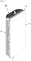
- FIG. 1 is a rear perspective view of a wireless communication apparatus according to an embodiment of the present disclosure.
- FIG. 2 is a front perspective view of the wireless communication apparatus according to an embodiment of the present disclosure.
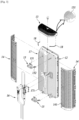
- FIG. 3 is an exploded perspective view of the wireless communication apparatus according to an embodiment of the present disclosure.
- a wireless communication apparatus 10 may include all or some of a main case 12, a random 11, a heat dissipation portion 17, an upper screen 13, a cover portion 14, and a handle portion 15.
- the main case 12 may form an accommodation space that opens forward, and may be formed to have a small front-to-back accommodation width over a substantially vertical length.
- the main case 12 may be formed in a rectangular parallelepiped shape.
- the random 11 may be disposed on a front surface of the main case 12.
- the random 11 may shield the accommodation space, be made of a material that allows electromagnetic waves to penetrate, and be fixed and disposed on the front side of the main case 12.
- the accommodation space may be formed between the random 11 and the main case 12.
- a plurality of heating elements may be disposed in the accommodation space.
- a PA (Power Amplifier) element, a semiconductor element for RFIC, or a Low Noise Amplifier (LNA) element may be disposed as the heating element in the accommodation space.
- the PA element is a transistor that is a main heat generation component of a highfrequency power amplifier, and is an RF element with high output power, and generates a large amount of heat as compared to an RFIC semiconductor element or LNA element.
- the heating element continuously generates heat
- the heat dissipation portion 17 disposed on a rear surface of the random 11 radiates the heat from the accommodation space to the outside.
- a plurality of heat dissipation fins 171 are formed to protrude from an opposite side of the accommodation space.
- the plurality of heat dissipation fins 171 have a maximized surface area that is in contact with the outside, thereby improving heat dissipation efficiency.
- the heat dissipation portion 17 may be integrally configured to cover the entire rear surface of the accommodation space, but the present disclosure is not limited thereto and one heat dissipation portion 17 may be disposed on each of the left and right sides, as illustrated in FIG. 3 .
- the upper screen 13 may be disposed in contact with a rear end of an upper surface of the main case, and have a plurality of first through holes 131 formed therein.
- the first through hole 131 may have a cross-section having any shape (for example, a circular or oval shape).
- a case in which the first through hole 131 has a circular shape will be described as an example.
- the upper screen 13 may be disposed close to a rear upper end of the heat dissipation portion 17, and heat generated from the plurality of heat dissipation fins 171 may be radiated through the plurality of first through holes 131 of the upper screen 13. Further, areas other than the plurality of first through holes 131 in the upper screen 13 may be made of a material that does not allow sunlight to pass through or reflects the sunlight. Therefore, the upper screen 13 serves as a screen so that the heat dissipation portion 17 is not directly irradiated with sunlight. That is, the upper screen 13 may be configured to prevent the heat dissipation portion 17 from being direct exposed to the sunlight and radiate heat generated in the heat dissipation portion 17 to the outside.
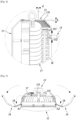
- FIG. 4 is a side cross-sectional view of the wireless communication apparatus according to an embodiment of the present disclosure.
- the upper screen 13 may be formed with a large thickness h to minimize an amount of sunlight with which the inside is irradiated.
- a thickness h of a plurality of upper screens 13 may be equal to or larger than twice a diameter d of the first through hole 131.
- the first through hole 131 may be formed to penetrate the upper screen 13 in a direction parallel to a longitudinal direction of the heat dissipation portion 17.
- the thickness of the upper screen 13 and the penetration direction of the first through hole 131 makes it possible to block the sunlight so that the inside is not irradiated with light other than light close to the penetration direction of the first through hole 131. That is, the upper screen 13 according to an embodiment of the present disclosure can radiate internal heat generated by the heat dissipation portion 17 to the outside and minimize an amount of sunlight from the outside that is radiated to the inside, thereby increasing a heat dissipation effect.
- the penetration direction of the first through hole 131 is not limited thereto, and the first through hole 131 may be formed to penetrate the upper screen 13 at an angle to the longitudinal direction of the heat dissipation portion 17.
- the upper screen 13 may be configured to be detachable and to be able to be assembled, and the upper screen 13 having the first through hole 131 penetrating in a direction in which sunlight is blocked as much as possible depending on a disposition direction of the wireless communication apparatus 10 may be appropriately assembled so that sunlight blocking efficiency can be maximized.
- the upper screen 13 may be disposed such that one end thereof is in contact with the rear end of the upper surface of the main case 12 and the other end thereof is in contact with an upper end of the cover portion 14. At least a portion of the upper screen 13 may have a horizontal surface, and at least another portion may have a downward slope to the outer side. Here, the outer side is the cover portion 14 side. That is, a portion of the upper screen 13 adjacent to the main case 12 has the horizontal surface, and a portion adjacent to the cover portion 14 has a downward inclined surface. Since the upper screen 13 has the downward inclined surface, the heat generated in the heat dissipation portion 17 can be radiated to the outside more efficiently.
- the cover portion 14 is disposed on a rear surface of the main case 12, is configured to be opened and closed, and has a plurality of second through holes 141 formed therein.
- the cover portion 14 can protect the cable 16 and the heat dissipation portion 17 disposed inside from external shock. Additionally, the cover portion is disposed on the rear surface of the main case 12, and the cable extended and disposed at a lower end of the wireless communication apparatus 10 of the related art is moved to a space between the cover portion 14 and the heat dissipation portion 17, thereby improving the aesthetics of the wireless communication apparatus 10.
- the plurality of second through holes 141 are formed in the cover portion 14, the plurality of second through holes 141 may be formed so that the heat dissipation portion 17 and the cable 16 are invisible from the outside.
- the second through holes 141 may be used as a passage for radiating the heat generated in the heat dissipation portion 17 to the outside, similar to the first through holes 131.
- FIG. 5 is a plan view of the wireless communication apparatus according to an embodiment of the present disclosure.
- the cover portion 14 may be opened and closed by pivoting around a vertical rotation shaft A1 or A2 located on at least one of left and right sides of the wireless communication apparatus 10.
- the upper screen 13 is omitted for convenience of description.
- the cover portion 14 may include two portions and may be opened and closed by pivoting around the vertical rotation shaft A1 located on the left side of the wireless communication apparatus 10 and the vertical rotation shaft A2 located on the right side of the wireless communication apparatus 10.
- cover portion 14 may include one cover portion 14 that covers the entire rear surface of the heat dissipation portion 17 and be opened and closed by pivoting around the vertical rotation shaft A1 or A2 located on one of the left and right sides of the wireless communication apparatus 10.
- opening and closing methods that may be modified by those skilled in the art fall within the scope of the present invention.
- the cover portion 14 may have a generally arc-shaped cross-sectional structure, but is not limited thereto and may have any shape as long as the shape can provide a sufficient space to dispose cables between the heat dissipation portion 17 and the cover portion 14. Since the heat dissipation fins 171 of the heat dissipation portion 17 have a high temperature when the wireless communication apparatus 10 is in operation, there is a risk of a burn if the heat dissipation fins 171 are exposed to the outside when a worker or the like performs maintenance of a plurality of wireless communication apparatuses 10 at a place at which the plurality of wireless communication apparatuses 10 are installed. In the present disclosure, there is an effect that it is possible to protect the worker from such a burn risk by additionally providing the cover portion 14. That is, the cover portion 14 may serve as a finger guard.
- the fixing portion 18 is configured to fix the cover portion 14 in an opened state when the cover portion 14 is opened.
- a locking portion may be formed to protrude at a free end of the fixing portion 18.
- the locking portion is configured to fit into a portion of an inner wall of the cover portion 14 in a state in which the cover portion 14 is opened.
- a fitting groove may be formed at a position corresponding to the locking portion on the inner wall of the cover portion 14.
- the handle portion 15 may be disposed to protrude to the outside through at least a portion of the cover portion 14. Accordingly, an opening corresponding to a position and shape of the handle portion 15 may be formed in the cover portion 14. At least one handle portion 15 may be disposed in the wireless communication apparatus 10, and may be disposed in an upper or lower portion of the rear surface of the wireless communication apparatus 10, as illustrated in the drawing. The handle portion 15 may serve as a handle when the wireless communication apparatus 10 is carried.
- the handle portion 15 may also serve as a guide that guides a movement of the cover portion 14 when the cover portion 14 is closed.
- the handle portion 15 may also serve as a support.
- a fixing surface 151 for maintaining a closed state when the cover portion 14 is closed may be formed in the handle portion 15. After the wireless communication apparatus 10 is subjected to maintenance and then the cover portion 14 is closed, the closed state of the cover portion 14 can be stably maintained by screw coupling or magnetic coupling between at least a portion of the cover portion 14 and the fixing surface 151.
- the handle portion 15 further includes a handle support portion 152 located on an inner side of the cover portion 14 and disposed to support a position of the handle portion 15.
- One end of the handle support portion 152 may be coupled to the main case 12 and/or the heat dissipation portion 17.
- the one end of the handle support portion 152 may be screwed to a coupling portion formed on the heat dissipation portion 17. Since a portion of the handle support portion 152 is disposed between the cover portion 14 and the heat dissipation portion 17, the internal cable 16 may be arranged using the portion of the handle support portion 152.
- the cable 16 hung on the handle support portion 152 does not affect a disposition form of the wireless communication apparatus 10 even when the wireless communication apparatus 10 is disposed uprightly in the longitudinal direction.
- cables protruding from a lower portion of the wireless communication apparatus 10 in the related art may be disposed on the inner side of the cover portion 14 so that the cables are invisible from the outside, and a disposition form of the cable may be fixed using the handle support portion 152.
- FIG. 6 is a rear view of the wireless communication apparatus according to an embodiment of the present disclosure.
- the wireless communication apparatus 10 when the wireless communication apparatus 10 is installed uprightly in the longitudinal direction, the cable 16 moves downward due to gravity. Therefore, a separate support portion or the like is required in order to fixedly position the cable 16 on the inner side the cover portion 14 and the heat dissipation portion 17.
- a configuration of the cover portion 14 is omitted for convenience of description. According to an embodiment of the present disclosure, it is possible to achieve efficient space utilization for arrangement of the cable 16 by hanging the cable 16 on the handle support portion 152 of the handle portion 15 disposed in an upper portion of the wireless communication apparatus 10. In addition, since the cable 16 is fixed by being hung on the handle support portion 152, it is possible to prevent a phenomenon in which the cable 16 flows to the outside when the cover portion 14 is opened in order to perform maintenance of the wireless communication apparatus 10.
Landscapes
- Engineering & Computer Science (AREA)
- Signal Processing (AREA)
- Microelectronics & Electronic Packaging (AREA)
- Computer Networks & Wireless Communication (AREA)
- Physics & Mathematics (AREA)
- Thermal Sciences (AREA)
- Transceivers (AREA)
- Details Of Aerials (AREA)
- Cooling Or The Like Of Electrical Apparatus (AREA)
Abstract
Description
- The present disclosure relates to a wireless communication apparatus.
- The content described in this section simply provides background information for the present disclosure and does not constitute related art.
- A wireless communication apparatus used to transmit and receive radio signals is generally installed in an outdoor environment, such as a roof of a building. A heat dissipation portion disposed at a rear surface of the wireless communication apparatus to radiate heat generated by a heating element disposed inside the wireless communication apparatus to the outside is generally disposed to be open. When the wireless communication apparatus is installed, aesthetics of the building are often damaged due to the heat dissipation portion, cables extending to a lower end of the wireless communication apparatus, or the like.
- Research is being conducted in various fields to improve a size and design of the wireless communication apparatus so that the aesthetics of the building are not damaged, but improvements in design and size are limited in terms of maintenance of functions of the wireless communication apparatus.
- When a screen for screening the heat dissipation portion is installed in order to improve aesthetics of the wireless communication apparatus, there is a problem that the performance of the wireless communication apparatus is degraded because heat generated from the heat dissipation portion is not radiated to the outside.
- A wireless communication apparatus according to an embodiment can have aesthetics of the wireless communication apparatus improved by providing an apparatus that can screen a heat dissipation portion and cables.
- The wireless communication apparatus according to an embodiment can radiate heat to the outside using a heat dissipation portion and block sunlight coming from the outside by providing an upper screen having through holes and an opening and closing portion.
- The wireless communication apparatus according to an embodiment can have convenience of maintenance of the wireless communication apparatus improved by providing a cover portion that can be opened and closed at a rear surface.
- The problems to be solved by the present disclosure are not limited to the problems mentioned above, and other problems not mentioned can be clearly understood by those skilled in the art from the description below
- According to at least one embodiment of the present disclosure, a wireless communication apparatus including a main case; a random disposed on a front surface of the main case and forming an accommodation space therein; a heat dissipation portion disposed at a rear surface of the random; an upper screen disposed in contact with a rear end of an upper surface of the main case and having a plurality of first through holes formed therein; and a cover portion disposed on a rear surface of the main case, configured to be opened and closed, and having a plurality of second through holes formed therein.
- A thickness of the upper screen may be equal to or larger than twice a diameter of the first through hole.
- The plurality of first through holes may have a circular or oval cross-section.
- The plurality of first through holes may be formed to penetrate the upper screen in a direction parallel to a longitudinal direction of the heat dissipation portion.
- The plurality of first through holes may be formed to penetrate the upper screen at an angle to a longitudinal direction of the heat dissipation portion.
- The wireless communication apparatus may further include one or more vertical rotation shafts located on at least one of left and right sides of the wireless communication apparatus so that the cover portion is opened and closed by pivoting around the vertical rotation shaft.
- At least a portion of the upper screen may have a horizontal surface, and at least another portion of the upper screen may have a downward slope to the outer side.
- The antenna apparatus may further include a fixing portion configured to fix the cover portion in an opened state when the cover portion is opened.
- The fixing portion may include a locking portion configured to fit into an inner wall of the cover portion, the locking portion being formed at a free end.
- The wireless communication apparatus may further comprise a handle portion formed to protrude to the outside through at least a portion of the cover portion, wherein an opening corresponding to a disposition position and shape of the handle portion is formed in the cover portion.
- The handle portion may further include a handle support portion located on an inner side of the cover portion and disposed to support the position of the handle portion.
- The wireless communication apparatus may further comprise a cable disposed between the cover portion and the heat dissipation portion, wherein a portion of the cable is hung on the handle support portion.
- According to an embodiment, there is an effect that it is possible to improve aesthetics of the wireless communication apparatus by providing the upper screen and the cover portion so that the heat dissipation portion and the cables are invisible from the outside.
- According to an embodiment, there is an effect that it is possible to maintain or improve a heat dissipation effect by the wireless communication apparatus including a component for screening the heat dissipation portion so that the heat dissipation portion is not exposed to the outside, and through holes through which heat can be radiated.
-
-
FIG. 1 is a rear perspective view of a wireless communication apparatus according to an embodiment of the present disclosure. -
FIG. 2 is a front perspective view of the wireless communication apparatus according to an embodiment of the present disclosure. -
FIG. 3 is an exploded perspective view of the wireless communication apparatus according to an embodiment of the present disclosure. -
FIG. 4 is a side cross-sectional view of the wireless communication apparatus according to an embodiment of the present disclosure. -
FIG. 5 is a plan view of the wireless communication apparatus according to an embodiment of the present disclosure. -
FIG. 6 is a rear view of the wireless communication apparatus according to an embodiment of the present disclosure. - Hereinafter, some embodiments of the present disclosure will be described in detail with reference to the accompanying illustrative drawings. In the following description, like reference numerals preferably designate like elements, although the elements are shown in different drawings. Further, in the following description of some embodiments, a detailed description of related known components and functions when considered to obscure the subject of the present disclosure will be omitted for the purpose of clarity and for brevity.
- Additionally, various ordinal numbers or alpha codes such as first, second, i), ii), a), b), etc., are prefixed solely to differentiate one component from the other but not to imply or suggest the substances, order, or sequence of the components. Throughout this specification, when a part "includes" or "comprises" a component, the part is meant to further include other components, not to exclude thereof unless specifically stated to the contrary.
-
FIG. 1 is a rear perspective view of a wireless communication apparatus according to an embodiment of the present disclosure. -
FIG. 2 is a front perspective view of the wireless communication apparatus according to an embodiment of the present disclosure. -
FIG. 3 is an exploded perspective view of the wireless communication apparatus according to an embodiment of the present disclosure. Referring toFIGS. 1 to 3 , awireless communication apparatus 10 may include all or some of amain case 12, a random 11, aheat dissipation portion 17, anupper screen 13, acover portion 14, and ahandle portion 15. - The
main case 12 may form an accommodation space that opens forward, and may be formed to have a small front-to-back accommodation width over a substantially vertical length. Themain case 12 may be formed in a rectangular parallelepiped shape. - The random 11 may be disposed on a front surface of the
main case 12. The random 11 may shield the accommodation space, be made of a material that allows electromagnetic waves to penetrate, and be fixed and disposed on the front side of themain case 12. - The accommodation space may be formed between the random 11 and the
main case 12. A plurality of heating elements may be disposed in the accommodation space. For example, a PA (Power Amplifier) element, a semiconductor element for RFIC, or a Low Noise Amplifier (LNA) element may be disposed as the heating element in the accommodation space. Here, the PA element is a transistor that is a main heat generation component of a highfrequency power amplifier, and is an RF element with high output power, and generates a large amount of heat as compared to an RFIC semiconductor element or LNA element. - While the
wireless communication apparatus 10 operates, the heating element continuously generates heat, and theheat dissipation portion 17 disposed on a rear surface of the random 11 radiates the heat from the accommodation space to the outside. In theheat dissipation portion 17, a plurality ofheat dissipation fins 171 are formed to protrude from an opposite side of the accommodation space. The plurality ofheat dissipation fins 171 have a maximized surface area that is in contact with the outside, thereby improving heat dissipation efficiency. Theheat dissipation portion 17 may be integrally configured to cover the entire rear surface of the accommodation space, but the present disclosure is not limited thereto and oneheat dissipation portion 17 may be disposed on each of the left and right sides, as illustrated inFIG. 3 . - The
upper screen 13 may be disposed in contact with a rear end of an upper surface of the main case, and have a plurality of first throughholes 131 formed therein. The first throughhole 131 may have a cross-section having any shape (for example, a circular or oval shape). Hereinafter, a case in which the first throughhole 131 has a circular shape will be described as an example. - The
upper screen 13 may be disposed close to a rear upper end of theheat dissipation portion 17, and heat generated from the plurality of heat dissipation fins 171 may be radiated through the plurality of first throughholes 131 of theupper screen 13. Further, areas other than the plurality of first throughholes 131 in theupper screen 13 may be made of a material that does not allow sunlight to pass through or reflects the sunlight. Therefore, theupper screen 13 serves as a screen so that theheat dissipation portion 17 is not directly irradiated with sunlight. That is, theupper screen 13 may be configured to prevent theheat dissipation portion 17 from being direct exposed to the sunlight and radiate heat generated in theheat dissipation portion 17 to the outside. -
FIG. 4 is a side cross-sectional view of the wireless communication apparatus according to an embodiment of the present disclosure. Referring toFIG. 4 , theupper screen 13 may be formed with a large thickness h to minimize an amount of sunlight with which the inside is irradiated. For example, a thickness h of a plurality ofupper screens 13 may be equal to or larger than twice a diameter d of the first throughhole 131. The first throughhole 131 may be formed to penetrate theupper screen 13 in a direction parallel to a longitudinal direction of theheat dissipation portion 17. - The thickness of the
upper screen 13 and the penetration direction of the first throughhole 131 makes it possible to block the sunlight so that the inside is not irradiated with light other than light close to the penetration direction of the first throughhole 131. That is, theupper screen 13 according to an embodiment of the present disclosure can radiate internal heat generated by theheat dissipation portion 17 to the outside and minimize an amount of sunlight from the outside that is radiated to the inside, thereby increasing a heat dissipation effect. - The penetration direction of the first through
hole 131 is not limited thereto, and the first throughhole 131 may be formed to penetrate theupper screen 13 at an angle to the longitudinal direction of theheat dissipation portion 17. Theupper screen 13 may be configured to be detachable and to be able to be assembled, and theupper screen 13 having the first throughhole 131 penetrating in a direction in which sunlight is blocked as much as possible depending on a disposition direction of thewireless communication apparatus 10 may be appropriately assembled so that sunlight blocking efficiency can be maximized. - The
upper screen 13 may be disposed such that one end thereof is in contact with the rear end of the upper surface of themain case 12 and the other end thereof is in contact with an upper end of thecover portion 14. At least a portion of theupper screen 13 may have a horizontal surface, and at least another portion may have a downward slope to the outer side. Here, the outer side is thecover portion 14 side. That is, a portion of theupper screen 13 adjacent to themain case 12 has the horizontal surface, and a portion adjacent to thecover portion 14 has a downward inclined surface. Since theupper screen 13 has the downward inclined surface, the heat generated in theheat dissipation portion 17 can be radiated to the outside more efficiently. - The
cover portion 14 is disposed on a rear surface of themain case 12, is configured to be opened and closed, and has a plurality of second throughholes 141 formed therein. Thecover portion 14 can protect thecable 16 and theheat dissipation portion 17 disposed inside from external shock. Additionally, the cover portion is disposed on the rear surface of themain case 12, and the cable extended and disposed at a lower end of thewireless communication apparatus 10 of the related art is moved to a space between thecover portion 14 and theheat dissipation portion 17, thereby improving the aesthetics of thewireless communication apparatus 10. Although the plurality of second throughholes 141 are formed in thecover portion 14, the plurality of second throughholes 141 may be formed so that theheat dissipation portion 17 and thecable 16 are invisible from the outside. The second throughholes 141 may be used as a passage for radiating the heat generated in theheat dissipation portion 17 to the outside, similar to the first throughholes 131. -
FIG. 5 is a plan view of the wireless communication apparatus according to an embodiment of the present disclosure. - Referring to
FIG. 5 , thecover portion 14 may be opened and closed by pivoting around a vertical rotation shaft A1 or A2 located on at least one of left and right sides of thewireless communication apparatus 10. InFIG. 5 , theupper screen 13 is omitted for convenience of description. As illustrated inFIG. 5 , thecover portion 14 may include two portions and may be opened and closed by pivoting around the vertical rotation shaft A1 located on the left side of thewireless communication apparatus 10 and the vertical rotation shaft A2 located on the right side of thewireless communication apparatus 10. However, the present disclosure is not limited thereto, and thecover portion 14 may include onecover portion 14 that covers the entire rear surface of theheat dissipation portion 17 and be opened and closed by pivoting around the vertical rotation shaft A1 or A2 located on one of the left and right sides of thewireless communication apparatus 10. In addition, opening and closing methods that may be modified by those skilled in the art fall within the scope of the present invention. - The
cover portion 14 may have a generally arc-shaped cross-sectional structure, but is not limited thereto and may have any shape as long as the shape can provide a sufficient space to dispose cables between theheat dissipation portion 17 and thecover portion 14. Since theheat dissipation fins 171 of theheat dissipation portion 17 have a high temperature when thewireless communication apparatus 10 is in operation, there is a risk of a burn if theheat dissipation fins 171 are exposed to the outside when a worker or the like performs maintenance of a plurality ofwireless communication apparatuses 10 at a place at which the plurality ofwireless communication apparatuses 10 are installed. In the present disclosure, there is an effect that it is possible to protect the worker from such a burn risk by additionally providing thecover portion 14. That is, thecover portion 14 may serve as a finger guard. - The fixing
portion 18 is configured to fix thecover portion 14 in an opened state when thecover portion 14 is opened. A locking portion may be formed to protrude at a free end of the fixingportion 18. The locking portion is configured to fit into a portion of an inner wall of thecover portion 14 in a state in which thecover portion 14 is opened. A fitting groove may be formed at a position corresponding to the locking portion on the inner wall of thecover portion 14. When thecover portion 14 is opened and thewireless communication apparatus 10 is subjected to maintenance, the fixingportion 18 can prevent thecover portion 14 from being closed due to wind, or the like. - The
handle portion 15 may be disposed to protrude to the outside through at least a portion of thecover portion 14. Accordingly, an opening corresponding to a position and shape of thehandle portion 15 may be formed in thecover portion 14. At least onehandle portion 15 may be disposed in thewireless communication apparatus 10, and may be disposed in an upper or lower portion of the rear surface of thewireless communication apparatus 10, as illustrated in the drawing. Thehandle portion 15 may serve as a handle when thewireless communication apparatus 10 is carried. - In addition, the
handle portion 15 may also serve as a guide that guides a movement of thecover portion 14 when thecover portion 14 is closed. When thewireless communication apparatus 10 is laid down so that the rear surface of thewireless communication apparatus 10 is directed to a floor, thehandle portion 15 may also serve as a support. - A fixing
surface 151 for maintaining a closed state when thecover portion 14 is closed may be formed in thehandle portion 15. After thewireless communication apparatus 10 is subjected to maintenance and then thecover portion 14 is closed, the closed state of thecover portion 14 can be stably maintained by screw coupling or magnetic coupling between at least a portion of thecover portion 14 and the fixingsurface 151. - The
handle portion 15 further includes ahandle support portion 152 located on an inner side of thecover portion 14 and disposed to support a position of thehandle portion 15. One end of thehandle support portion 152 may be coupled to themain case 12 and/or theheat dissipation portion 17. For example, the one end of thehandle support portion 152 may be screwed to a coupling portion formed on theheat dissipation portion 17. Since a portion of thehandle support portion 152 is disposed between thecover portion 14 and theheat dissipation portion 17, theinternal cable 16 may be arranged using the portion of thehandle support portion 152. Thecable 16 hung on thehandle support portion 152 does not affect a disposition form of thewireless communication apparatus 10 even when thewireless communication apparatus 10 is disposed uprightly in the longitudinal direction. That is, cables protruding from a lower portion of thewireless communication apparatus 10 in the related art may be disposed on the inner side of thecover portion 14 so that the cables are invisible from the outside, and a disposition form of the cable may be fixed using thehandle support portion 152. -
FIG. 6 is a rear view of the wireless communication apparatus according to an embodiment of the present disclosure. - Referring to
FIG. 6 , when thewireless communication apparatus 10 is installed uprightly in the longitudinal direction, thecable 16 moves downward due to gravity. Therefore, a separate support portion or the like is required in order to fixedly position thecable 16 on the inner side thecover portion 14 and theheat dissipation portion 17. InFIG. 6 , a configuration of thecover portion 14 is omitted for convenience of description. According to an embodiment of the present disclosure, it is possible to achieve efficient space utilization for arrangement of thecable 16 by hanging thecable 16 on thehandle support portion 152 of thehandle portion 15 disposed in an upper portion of thewireless communication apparatus 10. In addition, since thecable 16 is fixed by being hung on thehandle support portion 152, it is possible to prevent a phenomenon in which thecable 16 flows to the outside when thecover portion 14 is opened in order to perform maintenance of thewireless communication apparatus 10. - Although exemplary embodiments of the present disclosure have been described for illustrative purposes, those skilled in the art will appreciate that various modifications, additions, and substitutions are possible, without departing from the idea and scope of the claimed invention. Therefore, exemplary embodiments of the present disclosure have been described for the sake of brevity and clarity. The scope of the technical idea of the embodiments of the present disclosure is not limited by the illustrations. Accordingly, one of ordinary skill would understand the scope of the claimed invention is not to be limited by the above explicitly described embodiments but by the claims and equivalents thereof.
-
- 10: wireless communication apparatus 11: random
- 12: main case 13: upper screen
- 14: cover portion 15: handle portion
- 16: internal cable 17: heat dissipation portion
- 18: fixing portion
- This application claims priority from
Korean Patent Application No. 10-2021-0108902 filed on August 18, 2021
Claims (12)
- A wireless communication apparatus comprising:a main case;a random disposed on a front surface of the main case and forming an accommodation space therein;a heat dissipation portion disposed at a rear surface of the random;an upper screen disposed in contact with a rear end of an upper surface of the main case and having a plurality of first through holes formed therein; anda cover portion disposed on a rear surface of the main case, configured to be opened and closed, and having a plurality of second through holes formed therein.
- The wireless communication apparatus of claim 1, wherein a thickness of the upper screen is equal to or larger than twice a diameter of the first through hole.
- The wireless communication apparatus of claim 1, wherein the plurality of first through holes have a circular or oval cross-section.
- The wireless communication apparatus of claim 1, wherein the plurality of first through holes are formed to penetrate the upper screen in a direction parallel to a longitudinal direction of the heat dissipation portion.
- The wireless communication apparatus of claim 1, wherein the plurality of first through holes are formed to penetrate the upper screen at an angle to a longitudinal direction of the heat dissipation portion.
- The wireless communication apparatus of claim 1, further comprising:
one or more vertical rotation shafts located on at least one of left and right sides of the wireless communication apparatus so that the cover portion is opened and closed by pivoting around the vertical rotation shaft. - The wireless communication apparatus of claim 1, wherein at least a portion of the upper screen has a horizontal surface, and at least another portion of the upper screen has a downward slope to the outer side.
- The antenna apparatus of claim 1, further comprising:
a fixing portion configured to fix the cover portion in an opened state when the cover portion is opened. - The wireless communication apparatus of claim 8, wherein the fixing portion includes a locking portion configured to fit into an inner wall of the cover portion, the locking portion being formed at a free end.
- The wireless communication apparatus of claim 1, further comprising:a handle portion formed to protrude to the outside through at least a portion of the cover portion, whereinan opening corresponding to a disposition position and shape of the handle portion is formed in the cover portion.
- The wireless communication apparatus of claim 10, wherein the handle portion further includes a handle support portion located on an inner side of the cover portion and disposed to support the position of the handle portion.
- The wireless communication apparatus of claim 11, further comprising:a cable disposed between the cover portion and the heat dissipation portion, whereina portion of the cable is hung on the handle support portion.
Applications Claiming Priority (2)
| Application Number | Priority Date | Filing Date | Title |
|---|---|---|---|
| KR1020210108902A KR20230026818A (en) | 2021-08-18 | 2021-08-18 | Wireless Communication Device |
| PCT/KR2022/012077 WO2023022447A1 (en) | 2021-08-18 | 2022-08-12 | Wireless communication apparatus |
Publications (2)
| Publication Number | Publication Date |
|---|---|
| EP4391396A1 true EP4391396A1 (en) | 2024-06-26 |
| EP4391396A4 EP4391396A4 (en) | 2025-08-13 |
Family
ID=85240753
Family Applications (1)
| Application Number | Title | Priority Date | Filing Date |
|---|---|---|---|
| EP22858684.8A Pending EP4391396A4 (en) | 2021-08-18 | 2022-08-12 | WIRELESS COMMUNICATION DEVICE |
Country Status (6)
| Country | Link |
|---|---|
| US (1) | US20240196567A1 (en) |
| EP (1) | EP4391396A4 (en) |
| JP (1) | JP7630042B2 (en) |
| KR (1) | KR20230026818A (en) |
| CN (1) | CN117693899A (en) |
| WO (1) | WO2023022447A1 (en) |
Families Citing this family (1)
| Publication number | Priority date | Publication date | Assignee | Title |
|---|---|---|---|---|
| TWI876445B (en) * | 2023-07-27 | 2025-03-11 | 啟碁科技股份有限公司 | Electronic device |
Family Cites Families (24)
| Publication number | Priority date | Publication date | Assignee | Title |
|---|---|---|---|---|
| US4371757A (en) * | 1981-08-21 | 1983-02-01 | Northern Telecom Limited | Enclosure for outdoor cross-connect system for telecommunications |
| US5274731A (en) * | 1992-12-24 | 1993-12-28 | Adc Telecommunications, Inc. | Optical fiber cabinet |
| US6628521B2 (en) * | 2000-11-06 | 2003-09-30 | Adc Telecommunications, Inc. | Mechanical housing |
| DE60322488D1 (en) * | 2002-09-27 | 2008-09-11 | Fujitsu Ltd | Radio for outdoor use |
| US7031158B2 (en) * | 2002-10-30 | 2006-04-18 | Charles Industries, Ltd. | Heat pipe cooled electronics enclosure |
| US7050765B2 (en) * | 2003-01-08 | 2006-05-23 | Xytrans, Inc. | Highly integrated microwave outdoor unit (ODU) |
| KR100918832B1 (en) * | 2007-11-20 | 2009-09-25 | 주식회사 서화정보통신 | Wireless repeater |
| JP5017088B2 (en) * | 2007-12-27 | 2012-09-05 | 三洋電機株式会社 | Electronic equipment cooling device |
| US8004844B2 (en) * | 2008-03-12 | 2011-08-23 | Kmw, Inc. | Enclosure device of wireless communication apparatus |
| JP2009274380A (en) * | 2008-05-16 | 2009-11-26 | Brother Ind Ltd | Carrying bag for printer |
| US7864534B2 (en) * | 2008-06-11 | 2011-01-04 | Adc Telecommunications, Inc. | Apparatus for mounting a module and enabling heat conduction from the module to the mounting surface |
| KR101036769B1 (en) * | 2009-01-23 | 2011-05-25 | 주식회사알에프윈도우 | Mobile repeater |
| BR112012013364A8 (en) * | 2009-12-02 | 2018-02-06 | Andrew Llc | PANEL ANTENNA THAT HAS SEALED RADIO BOX |
| CN103596297B (en) * | 2012-08-13 | 2017-04-12 | 华为技术有限公司 | Radio remote unit devices and assemblies thereof |
| KR101769524B1 (en) * | 2012-11-16 | 2017-08-21 | 주식회사 케이엠더블유 | Small-sized base station device in mobile communication system |
| KR101668265B1 (en) * | 2013-09-06 | 2016-10-24 | 주식회사 케이엠더블유 | High power LED lighting |
| KR101581116B1 (en) * | 2014-04-05 | 2015-12-29 | 엘지전자 주식회사 | Dehumidifier |
| KR102166445B1 (en) * | 2014-04-29 | 2020-10-15 | 엘지전자 주식회사 | Dehumidifier and water tank for Dehumidifier |
| CN104684363B (en) * | 2015-02-13 | 2017-07-21 | 华为技术有限公司 | A kind of outdoor display screen and communication equipment |
| EP3254334B1 (en) * | 2015-02-26 | 2023-11-22 | Huawei Technologies Co., Ltd. | A radio unit housing and a base station antenna module |
| CN112352348B (en) * | 2018-04-11 | 2024-07-02 | 株式会社Kmw | Multiple input/output antenna device |
| KR102528197B1 (en) * | 2018-05-31 | 2023-05-04 | 주식회사 케이엠더블유 | Cooling device for antenna apparatus |
| KR102711795B1 (en) * | 2019-02-01 | 2024-09-30 | 주식회사 케이엠더블유 | Wireless Communication Device |
| WO2021054755A1 (en) * | 2019-09-19 | 2021-03-25 | 주식회사 케이엠더블유 | Antenna device |
-
2021
- 2021-08-18 KR KR1020210108902A patent/KR20230026818A/en active Pending
-
2022
- 2022-08-12 CN CN202280051743.4A patent/CN117693899A/en active Pending
- 2022-08-12 EP EP22858684.8A patent/EP4391396A4/en active Pending
- 2022-08-12 JP JP2024503372A patent/JP7630042B2/en active Active
- 2022-08-12 WO PCT/KR2022/012077 patent/WO2023022447A1/en not_active Ceased
-
2024
- 2024-02-17 US US18/444,683 patent/US20240196567A1/en active Pending
Also Published As
| Publication number | Publication date |
|---|---|
| JP7630042B2 (en) | 2025-02-14 |
| US20240196567A1 (en) | 2024-06-13 |
| JP2024528657A (en) | 2024-07-30 |
| KR20230026818A (en) | 2023-02-27 |
| CN117693899A (en) | 2024-03-12 |
| WO2023022447A1 (en) | 2023-02-23 |
| EP4391396A4 (en) | 2025-08-13 |
Similar Documents
| Publication | Publication Date | Title |
|---|---|---|
| US20240196567A1 (en) | Wireless communication apparatus | |
| US9356359B2 (en) | Active antenna system (AAS) radio frequency (RF) module with heat sink integrated antenna reflector | |
| CN109219905A (en) | Base station antenna including complementary array | |
| WO2019043046A1 (en) | Lamp post with improved cooling | |
| US20110309996A1 (en) | Strand mountable antenna enclosure for wireless communication access system | |
| US8555591B2 (en) | Outdoor enclosure louver system | |
| EP2551601B1 (en) | Domestic appliance with a domestic appliance door and a lighting device | |
| GB2312099A (en) | Shielding and ventilation of cabinets | |
| KR101436910B1 (en) | Electromagnetic shielding rack | |
| CN209626424U (en) | Antenna equipment | |
| KR102463545B1 (en) | Cooling device for antenna apparatus | |
| CN102369635A (en) | Panel antenna having sealed radio enclosure | |
| US6462717B1 (en) | Enclosure for microwave radio transceiver with integral refractive antenna | |
| US5986618A (en) | Combined solar shield and antenna ground plane structure for an electrical assembly | |
| US20200146257A9 (en) | Pet cage | |
| KR102353884B1 (en) | Switchgear with natural cooling structure | |
| KR20230096083A (en) | Air flow structure for connector assembly | |
| KR101077532B1 (en) | Outdoor-type access point apparatus | |
| KR102353840B1 (en) | Switchgear with natural cooling structure | |
| ES3047871T3 (en) | Location determiner | |
| US2115789A (en) | Directional antenna system | |
| US10920961B2 (en) | Lighting unit | |
| CN207543481U (en) | The outdoor crate of telecommunication apparatus | |
| JP4715643B2 (en) | Radio wave directivity control device | |
| KR102353830B1 (en) | Switchgear with natural cooling structure |
Legal Events
| Date | Code | Title | Description |
|---|---|---|---|
| STAA | Information on the status of an ep patent application or granted ep patent |
Free format text: STATUS: THE INTERNATIONAL PUBLICATION HAS BEEN MADE |
|
| PUAI | Public reference made under article 153(3) epc to a published international application that has entered the european phase |
Free format text: ORIGINAL CODE: 0009012 |
|
| STAA | Information on the status of an ep patent application or granted ep patent |
Free format text: STATUS: REQUEST FOR EXAMINATION WAS MADE |
|
| 17P | Request for examination filed |
Effective date: 20240215 |
|
| AK | Designated contracting states |
Kind code of ref document: A1 Designated state(s): AL AT BE BG CH CY CZ DE DK EE ES FI FR GB GR HR HU IE IS IT LI LT LU LV MC MK MT NL NO PL PT RO RS SE SI SK SM TR |
|
| DAV | Request for validation of the european patent (deleted) | ||
| DAX | Request for extension of the european patent (deleted) | ||
| REG | Reference to a national code |
Ref country code: DE Ref legal event code: R079 Free format text: PREVIOUS MAIN CLASS: H04B0001380000 Ipc: H04B0001036000 |
|
| A4 | Supplementary search report drawn up and despatched |
Effective date: 20250711 |
|
| RIC1 | Information provided on ipc code assigned before grant |
Ipc: H04B 1/036 20060101AFI20250707BHEP Ipc: H04B 1/3888 20150101ALI20250707BHEP Ipc: H01Q 1/02 20060101ALI20250707BHEP Ipc: H01Q 1/42 20060101ALI20250707BHEP Ipc: H04B 1/08 20060101ALN20250707BHEP |