EP4391328A1 - Actuator - Google Patents
Actuator Download PDFInfo
- Publication number
- EP4391328A1 EP4391328A1 EP22870012.6A EP22870012A EP4391328A1 EP 4391328 A1 EP4391328 A1 EP 4391328A1 EP 22870012 A EP22870012 A EP 22870012A EP 4391328 A1 EP4391328 A1 EP 4391328A1
- Authority
- EP
- European Patent Office
- Prior art keywords
- worm
- output shaft
- electric motor
- control board
- gear
- Prior art date
- Legal status (The legal status is an assumption and is not a legal conclusion. Google has not performed a legal analysis and makes no representation as to the accuracy of the status listed.)
- Withdrawn
Links
Images


Classifications
-
- H—ELECTRICITY
- H02—GENERATION; CONVERSION OR DISTRIBUTION OF ELECTRIC POWER
- H02K—DYNAMO-ELECTRIC MACHINES
- H02K7/00—Arrangements for handling mechanical energy structurally associated with dynamo-electric machines, e.g. structural association with mechanical driving motors or auxiliary dynamo-electric machines
- H02K7/10—Structural association with clutches, brakes, gears, pulleys or mechanical starters
-
- H—ELECTRICITY
- H02—GENERATION; CONVERSION OR DISTRIBUTION OF ELECTRIC POWER
- H02K—DYNAMO-ELECTRIC MACHINES
- H02K11/00—Structural association of dynamo-electric machines with electric components or with devices for shielding, monitoring or protection
- H02K11/30—Structural association with control circuits or drive circuits
- H02K11/38—Control circuits or drive circuits associated with geared commutator motors of the worm-and-wheel type
-
- F—MECHANICAL ENGINEERING; LIGHTING; HEATING; WEAPONS; BLASTING
- F16—ENGINEERING ELEMENTS AND UNITS; GENERAL MEASURES FOR PRODUCING AND MAINTAINING EFFECTIVE FUNCTIONING OF MACHINES OR INSTALLATIONS; THERMAL INSULATION IN GENERAL
- F16H—GEARING
- F16H1/00—Toothed gearings for conveying rotary motion
- F16H1/02—Toothed gearings for conveying rotary motion without gears having orbital motion
- F16H1/04—Toothed gearings for conveying rotary motion without gears having orbital motion involving only two intermeshing members
- F16H1/06—Toothed gearings for conveying rotary motion without gears having orbital motion involving only two intermeshing members with parallel axes
-
- F—MECHANICAL ENGINEERING; LIGHTING; HEATING; WEAPONS; BLASTING
- F16—ENGINEERING ELEMENTS AND UNITS; GENERAL MEASURES FOR PRODUCING AND MAINTAINING EFFECTIVE FUNCTIONING OF MACHINES OR INSTALLATIONS; THERMAL INSULATION IN GENERAL
- F16H—GEARING
- F16H1/00—Toothed gearings for conveying rotary motion
- F16H1/02—Toothed gearings for conveying rotary motion without gears having orbital motion
- F16H1/04—Toothed gearings for conveying rotary motion without gears having orbital motion involving only two intermeshing members
- F16H1/12—Toothed gearings for conveying rotary motion without gears having orbital motion involving only two intermeshing members with non-parallel axes
- F16H1/16—Toothed gearings for conveying rotary motion without gears having orbital motion involving only two intermeshing members with non-parallel axes comprising worm and worm-wheel
-
- H—ELECTRICITY
- H02—GENERATION; CONVERSION OR DISTRIBUTION OF ELECTRIC POWER
- H02K—DYNAMO-ELECTRIC MACHINES
- H02K11/00—Structural association of dynamo-electric machines with electric components or with devices for shielding, monitoring or protection
- H02K11/20—Structural association of dynamo-electric machines with electric components or with devices for shielding, monitoring or protection for measuring, monitoring, testing, protecting or switching
- H02K11/21—Devices for sensing speed or position, or actuated thereby
- H02K11/215—Magnetic effect devices, e.g. Hall-effect or magneto-resistive elements
-
- H—ELECTRICITY
- H02—GENERATION; CONVERSION OR DISTRIBUTION OF ELECTRIC POWER
- H02K—DYNAMO-ELECTRIC MACHINES
- H02K23/00—DC commutator motors or generators having mechanical commutator; Universal AC/DC commutator motors
- H02K23/68—Structural association with auxiliary mechanical devices, e.g. with clutches or brakes
-
- H—ELECTRICITY
- H02—GENERATION; CONVERSION OR DISTRIBUTION OF ELECTRIC POWER
- H02K—DYNAMO-ELECTRIC MACHINES
- H02K5/00—Casings; Enclosures; Supports
- H02K5/04—Casings or enclosures characterised by the shape, form or construction thereof
- H02K5/22—Auxiliary parts of casings not covered by groups H02K5/06-H02K5/20, e.g. shaped to form connection boxes or terminal boxes
- H02K5/225—Terminal boxes or connection arrangements
-
- H—ELECTRICITY
- H02—GENERATION; CONVERSION OR DISTRIBUTION OF ELECTRIC POWER
- H02K—DYNAMO-ELECTRIC MACHINES
- H02K7/00—Arrangements for handling mechanical energy structurally associated with dynamo-electric machines, e.g. structural association with mechanical driving motors or auxiliary dynamo-electric machines
- H02K7/10—Structural association with clutches, brakes, gears, pulleys or mechanical starters
- H02K7/116—Structural association with clutches, brakes, gears, pulleys or mechanical starters with gears
- H02K7/1163—Structural association with clutches, brakes, gears, pulleys or mechanical starters with gears where at least two gears have non-parallel axes without having orbital motion
- H02K7/1166—Structural association with clutches, brakes, gears, pulleys or mechanical starters with gears where at least two gears have non-parallel axes without having orbital motion comprising worm and worm-wheel
-
- H—ELECTRICITY
- H02—GENERATION; CONVERSION OR DISTRIBUTION OF ELECTRIC POWER
- H02K—DYNAMO-ELECTRIC MACHINES
- H02K2211/00—Specific aspects not provided for in the other groups of this subclass relating to measuring or protective devices or electric components
- H02K2211/03—Machines characterised by circuit boards, e.g. pcb
Definitions
- the present disclosure relates to an actuator having an electric motor as a driving source.
- An actuator disclosed in Patent Document 1 comprises a first speed reducer including a gear disposed at an end of a worm and a gear disposed on an output shaft of an electric motor, and a second speed reducer including the worm and a worm wheel.
- Patent Document 1 Japanese Unexamined Patent Application Publication No. 2019-187028
- a connector for an external connection is situated on a side opposite to the electric motor across the worm wheel in a direction parallel to the output shaft of the electric motor (hereinafter also referred to as “longitudinal direction").
- longitudinal direction a direction parallel to the output shaft of the electric motor
- the present disclosure will disclose examples of an actuator having a longitudinal dimension that can be easily reduced.
- An actuator includes an electric motor; a first gear disposed on an output shaft of the electric motor; a second gear meshed with the first gear to cooperate with the first gear and transmit a rotation of the output shaft as a decelerated rotation; a worm extending in a direction parallel to the output shaft, the second gear being disposed on one end side of the worm in a direction of extension of the worm; a worm wheel meshed with the worm and situated on the same side as the output shaft relative to the worm; and a control board for controlling the electric motor, the control board being situated between the electric motor and the worm wheel.
- the control board includes a connector for an external connection.
- the actuator having the aforementioned configuration has a longitudinal dimension that is easily reduced.
- the present embodiment is one example of an actuator of the present disclosure being applied to actuators for vehicles such as a wiper driving device and a power window device.
- an actuator 1 includes at least an electric motor 10, a first speed reducer 20, a second speed reducer 30, a controller 40, a housing 50 for housing these elements 10 to 40, and the like.
- the electric motor 10 is a driving source that generates a rotational driving force.
- the first speed reducer 20 and the second speed reducer 30 are speed reduction devices for externally outputting power output of the electric motor 10 as a decelerated rotation.
- the controller 40 controls the rotation and cessation of the electric motor 10.
- the first speed reducer 20 includes a first gear 21, a second gear 22, and the like.
- the first gear 21 is disposed on a leading end side of an output shaft 11 of the electric motor 10 and integrally rotates with the output shaft 11.
- the second gear 22 meshes with the first gear 21 and cooperates with the first gear 21 to transmit the rotation of the output shaft 11 as a decelerated rotation.
- the first gear 21 and the second gear 22 according to the present embodiment include spur gears or helical gears.
- the second speed reducer 30 includes a worm 31, a worm wheel 32, and the like.
- the worm 31 extends in a direction parallel to the output shaft 11 of the electric motor 10 (hereinafter also referred to as "longitudinal direction"), and the second gear 22 is disposed on one end side of the worm 31 in a direction of extension of the worm 31 (on the left side of FIG. 1 ).
- the worm 31 integrally rotates with the second gear 22.
- the worm wheel 32 meshes with the worm 31 to rotate and is situated on the same side as the output shaft 11 relative to the worm 31.
- the output shaft 11 and the worm wheel 32 are situated on the bottom side of FIG. 1 relative to the worm 31.
- the second speed reducer 30 transmits the rotation of the electric motor 10, which was transmitted by the first speed reducer 20 as a decelerated rotation, as a further decelerated rotation.
- the decelerated rotation transmitted by the second speed reducer 30 is externally outputted by using a central shaft (not illustrated) of the worm wheel 32 as an output shaft.
- the controller 40 includes at least a control board 41, a connector 42, a brush 43, a commutator 44, and the like.
- the control board 41 is situated between the electric motor 10 and the worm wheel 32 with its board surface facing the output shaft 11.
- the control board 41 is situated on a side opposite to the worm 31 across the output shaft 11. In other words, the control board 41 is situated on the bottom side of FIG. 1 relative to the output shaft 11 such that the board surface of the control board 41 is parallel to the output shaft 11.
- the connector 42 is a part for an external connection and is disposed on the control board 41. Although it does not limit the present disclosure, the connector 42 according to the present embodiment has a convex shape as shown in FIG. 2 . A terminal of the connector 42 is fixed to the control board 41.
- a part of the control board 41 facing the output shaft 11 includes a power supplier 45.
- the power supplier 45 supplies the brush 43 with an electric power.
- the brush 43 supplies a coil of the electric motor 10 with an electric power via a commutator 44.
- a sensor 46 for sensing a rotation of the electric motor 10 is mounted on the controller 40.
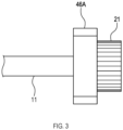
- the sensor 46 senses a rotation of the electric motor 10 in cooperation with a permanent magnet 46A (see FIG. 3 ) that integrally rotates with the output shaft 11.
- the senor 46 includes a magnetic sensor such as a Hall IC.
- the sensor 46 senses positions of magnetic poles of the permanent magnet 46A that alternate in association with a rotation of the output shaft 11.
- the operation of the electric motor 10 can be externally adjusted according to a driving state of the electric motor 10, and at the same time, the rotational position of the electric motor 10 can be sensed by a simple configuration using a magnet.
- the control board 41 is situated between the electric motor 10 and the worm wheel 32, and the connector 42 is disposed on the control board 41.
- the longitudinal dimension of the actuator 1 can be reduced easily compared to that of the actuator disclosed in Patent Document 1.
- the width of the actuator 1 which is the dimension of the actuator 1 in a direction orthogonal to the longitudinal direction, can be easily reduced. In other words, if the worm wheel 32 is situated on the side opposite to the output shaft 11 across the worm 31, it is difficult to reduce the width of the actuator 1.
- the actuator according to the aforementioned embodiment includes an electric motor having the brush 43 and the commutator 44.
- the present disclosure is nevertheless not limited thereto.
- the present disclosure may include a DC brushless motor using the sensor 46, for example.
- the sensor 46 includes a magnetic sensor such as a Hall IC.
- the present disclosure is nevertheless not limited thereto.
- the present disclosure may include an optical sensor having a light emitter and a photodetector, for example.
- the present disclosure is not limited to the aforementioned embodiments as long as it conforms to the gist of the claims. Therefore, the present disclosure may include a configuration obtained by combining at least two of the aforementioned embodiments, or a configuration in which any one of the elements of the aforementioned embodiments is eliminated.
Landscapes
- Engineering & Computer Science (AREA)
- Power Engineering (AREA)
- General Engineering & Computer Science (AREA)
- Microelectronics & Electronic Packaging (AREA)
- Mechanical Engineering (AREA)
- Connection Of Motors, Electrical Generators, Mechanical Devices, And The Like (AREA)
- Gear Transmission (AREA)
Abstract
Description
- This international application claims the benefit of
Japanese Patent Application No. 2021-149410 filed on September 14, 2021 Japanese Patent Application No. 2021-149410 - The present disclosure relates to an actuator having an electric motor as a driving source.
- An actuator disclosed in Patent Document 1 comprises a first speed reducer including a gear disposed at an end of a worm and a gear disposed on an output shaft of an electric motor, and a second speed reducer including the worm and a worm wheel.
- Patent Document 1:
Japanese Unexamined Patent Application Publication No. 2019-187028 - In the actuator disclosed in Patent Document 1, a connector for an external connection is situated on a side opposite to the electric motor across the worm wheel in a direction parallel to the output shaft of the electric motor (hereinafter also referred to as "longitudinal direction"). Thus, it is difficult to reduce a size in the longitudinal direction (hereinafter also referred to as "longitudinal dimension") of the actuator disclosed in Patent Document 1.
- In consideration of the aforementioned problem, the present disclosure will disclose examples of an actuator having a longitudinal dimension that can be easily reduced.
- An actuator according to one aspect of the present disclosure includes an electric motor; a first gear disposed on an output shaft of the electric motor; a second gear meshed with the first gear to cooperate with the first gear and transmit a rotation of the output shaft as a decelerated rotation; a worm extending in a direction parallel to the output shaft, the second gear being disposed on one end side of the worm in a direction of extension of the worm; a worm wheel meshed with the worm and situated on the same side as the output shaft relative to the worm; and a control board for controlling the electric motor, the control board being situated between the electric motor and the worm wheel. The control board includes a connector for an external connection.
- Compared with the actuator disclosed in Patent Document 1, the actuator having the aforementioned configuration has a longitudinal dimension that is easily reduced.
- Embodiments of the present disclosure will be described hereinafter with reference to the accompanying drawings.
-
FIG. 1 is a diagram showing an actuator according to a first embodiment. -
FIG. 2 is a diagram showing a first speed reducer and other elements of the actuator according to the first embodiment. -
FIG. 3 is a diagram showing a configuration for detecting a rotation of an electric motor. - 1...actuator; 10...electric motor; 11...output shaft; 20...first speed reducer; 21...first gear; 22...second gear; 30...second speed reducer; 31...worm; 32...worm wheel; 40...controller; 41...control board; 42...connector; 43...brush; 44...commutator; 45...power supplier; 46...sensor; 46A...permanent magnet.
- The embodiments described below are examples of embodiments that belong to the technical scope of the present disclosure. Matters used to specify the invention or the like recited in the claims will not be limited to particular configurations, structures or the like described in the embodiments below.
- Two or more of each of members or parts explained below may be provided as long as it is technically practicable.
- The present embodiment is one example of an actuator of the present disclosure being applied to actuators for vehicles such as a wiper driving device and a power window device.
- As shown in
FIG. 1 , an actuator 1 according to the present embodiment includes at least anelectric motor 10, afirst speed reducer 20, asecond speed reducer 30, acontroller 40, ahousing 50 for housing theseelements 10 to 40, and the like. - The
electric motor 10 is a driving source that generates a rotational driving force. The first speed reducer 20 and thesecond speed reducer 30 are speed reduction devices for externally outputting power output of theelectric motor 10 as a decelerated rotation. Thecontroller 40 controls the rotation and cessation of theelectric motor 10. - The
first speed reducer 20 includes afirst gear 21, asecond gear 22, and the like. Thefirst gear 21 is disposed on a leading end side of anoutput shaft 11 of theelectric motor 10 and integrally rotates with theoutput shaft 11. - The
second gear 22 meshes with thefirst gear 21 and cooperates with thefirst gear 21 to transmit the rotation of theoutput shaft 11 as a decelerated rotation. Although it does not limit the present disclosure, thefirst gear 21 and thesecond gear 22 according to the present embodiment include spur gears or helical gears. - The
second speed reducer 30 includes aworm 31, aworm wheel 32, and the like. Theworm 31 extends in a direction parallel to theoutput shaft 11 of the electric motor 10 (hereinafter also referred to as "longitudinal direction"), and thesecond gear 22 is disposed on one end side of theworm 31 in a direction of extension of the worm 31 (on the left side ofFIG. 1 ). Theworm 31 integrally rotates with thesecond gear 22. - The
worm wheel 32 meshes with theworm 31 to rotate and is situated on the same side as theoutput shaft 11 relative to theworm 31. In other words, theoutput shaft 11 and theworm wheel 32 are situated on the bottom side ofFIG. 1 relative to theworm 31. - The
second speed reducer 30 transmits the rotation of theelectric motor 10, which was transmitted by thefirst speed reducer 20 as a decelerated rotation, as a further decelerated rotation. The decelerated rotation transmitted by thesecond speed reducer 30 is externally outputted by using a central shaft (not illustrated) of theworm wheel 32 as an output shaft. - The
controller 40 includes at least acontrol board 41, aconnector 42, abrush 43, acommutator 44, and the like. Thecontrol board 41 is situated between theelectric motor 10 and theworm wheel 32 with its board surface facing theoutput shaft 11. - The
control board 41 is situated on a side opposite to theworm 31 across theoutput shaft 11. In other words, thecontrol board 41 is situated on the bottom side ofFIG. 1 relative to theoutput shaft 11 such that the board surface of thecontrol board 41 is parallel to theoutput shaft 11. - The
connector 42 is a part for an external connection and is disposed on thecontrol board 41. Although it does not limit the present disclosure, theconnector 42 according to the present embodiment has a convex shape as shown inFIG. 2 . A terminal of theconnector 42 is fixed to thecontrol board 41. - As shown in
FIG. 1 , a part of thecontrol board 41 facing theoutput shaft 11 includes apower supplier 45. Thepower supplier 45 supplies thebrush 43 with an electric power. Thebrush 43 supplies a coil of theelectric motor 10 with an electric power via acommutator 44. - A
sensor 46 for sensing a rotation of theelectric motor 10 is mounted on thecontroller 40. Thesensor 46 senses a rotation of theelectric motor 10 in cooperation with apermanent magnet 46A (seeFIG. 3 ) that integrally rotates with theoutput shaft 11. - Although it does not limit the present disclosure, the
sensor 46 according to the present embodiment includes a magnetic sensor such as a Hall IC. Thesensor 46 senses positions of magnetic poles of thepermanent magnet 46A that alternate in association with a rotation of theoutput shaft 11. - Thus, in the actuator 1 according to the present embodiment, the operation of the
electric motor 10 can be externally adjusted according to a driving state of theelectric motor 10, and at the same time, the rotational position of theelectric motor 10 can be sensed by a simple configuration using a magnet. - In the actuator 1 according to the present embodiment, the
control board 41 is situated between theelectric motor 10 and theworm wheel 32, and theconnector 42 is disposed on thecontrol board 41. Thus, according to the actuator 1 of the present embodiment, the longitudinal dimension of the actuator 1 can be reduced easily compared to that of the actuator disclosed in Patent Document 1. - In addition, since the
worm wheel 32 is situated on the same side as theoutput shaft 11 relative to theworm 31, the width of the actuator 1, which is the dimension of the actuator 1 in a direction orthogonal to the longitudinal direction, can be easily reduced. In other words, if theworm wheel 32 is situated on the side opposite to theoutput shaft 11 across theworm 31, it is difficult to reduce the width of the actuator 1. - The actuator according to the aforementioned embodiment includes an electric motor having the
brush 43 and thecommutator 44. The present disclosure is nevertheless not limited thereto. Alternatively, the present disclosure may include a DC brushless motor using thesensor 46, for example. - The
sensor 46 according to the aforementioned embodiment includes a magnetic sensor such as a Hall IC. The present disclosure is nevertheless not limited thereto. Alternatively, the present disclosure may include an optical sensor having a light emitter and a photodetector, for example. - Furthermore, the present disclosure is not limited to the aforementioned embodiments as long as it conforms to the gist of the claims. Therefore, the present disclosure may include a configuration obtained by combining at least two of the aforementioned embodiments, or a configuration in which any one of the elements of the aforementioned embodiments is eliminated.
Claims (3)
- An actuator comprising:an electric motor;a first gear disposed on an output shaft of the electric motor;a second gear meshed with the first gear to cooperate with the first gear and transmit a rotation of the output shaft as a decelerated rotation;a worm extending in a direction parallel to the output shaft, the second gear being disposed on one end side of the worm in a direction of extension of the worm;a worm wheel meshed with the worm and situated on a same side as the output shaft relative to the worm; anda control board for controlling the electric motor, the control board being situated between the electric motor and the worm wheel,wherein the control board includes a connector for an external connection.
- The actuator according to claim 1,wherein the control board is situated such that a board surface of the control board faces the output shaft, andwherein a power supplier configured to supply a brush with an electric power and a sensor configured to sense a rotation of the electric motor are mounted on a part of the control board facing the output shaft.
- The actuator according to claim 2,
wherein the control board is situated on a side opposite to the worm across the output shaft.
Applications Claiming Priority (2)
| Application Number | Priority Date | Filing Date | Title |
|---|---|---|---|
| JP2021149410A JP2023042221A (en) | 2021-09-14 | 2021-09-14 | actuator |
| PCT/JP2022/034465 WO2023042865A1 (en) | 2021-09-14 | 2022-09-14 | Actuator |
Publications (1)
| Publication Number | Publication Date |
|---|---|
| EP4391328A1 true EP4391328A1 (en) | 2024-06-26 |
Family
ID=85602946
Family Applications (1)
| Application Number | Title | Priority Date | Filing Date |
|---|---|---|---|
| EP22870012.6A Withdrawn EP4391328A1 (en) | 2021-09-14 | 2022-09-14 | Actuator |
Country Status (5)
| Country | Link |
|---|---|
| US (1) | US20240429791A1 (en) |
| EP (1) | EP4391328A1 (en) |
| JP (1) | JP2023042221A (en) |
| CN (1) | CN117981204A (en) |
| WO (1) | WO2023042865A1 (en) |
Family Cites Families (6)
| Publication number | Priority date | Publication date | Assignee | Title |
|---|---|---|---|---|
| JP2004166481A (en) * | 2002-09-17 | 2004-06-10 | Asmo Co Ltd | Motor and power window motor |
| RU2510561C2 (en) * | 2009-07-30 | 2014-03-27 | Мицуба Корпорейшн | Gearmotor |
| JP2013176209A (en) * | 2012-02-24 | 2013-09-05 | Ntn Corp | Motor drive device for vehicle |
| DE102013006854A1 (en) * | 2012-04-26 | 2013-10-31 | Asmo Co., Ltd. | engine |
| USRE47564E1 (en) * | 2012-04-26 | 2019-08-06 | Denso Corporation | Motor |
| JP7077109B2 (en) | 2018-04-05 | 2022-05-30 | 株式会社ミツバ | Motor with reducer, wiper drive device and power window device |
-
2021
- 2021-09-14 JP JP2021149410A patent/JP2023042221A/en active Pending
-
2022
- 2022-09-14 CN CN202280061323.4A patent/CN117981204A/en active Pending
- 2022-09-14 EP EP22870012.6A patent/EP4391328A1/en not_active Withdrawn
- 2022-09-14 US US18/689,946 patent/US20240429791A1/en not_active Abandoned
- 2022-09-14 WO PCT/JP2022/034465 patent/WO2023042865A1/en not_active Ceased
Also Published As
| Publication number | Publication date |
|---|---|
| JP2023042221A (en) | 2023-03-27 |
| CN117981204A (en) | 2024-05-03 |
| US20240429791A1 (en) | 2024-12-26 |
| WO2023042865A1 (en) | 2023-03-23 |
Similar Documents
| Publication | Publication Date | Title |
|---|---|---|
| KR102610672B1 (en) | Actuator | |
| CN103124666B (en) | The deflector comprising electrical motor, control unit and sensing device and the electric power steering system of being furnished with deflector | |
| JP4848842B2 (en) | Brushless motor and electric power steering device | |
| US20160241108A1 (en) | Brushless wiper motor | |
| CN103415983B (en) | motor drive | |
| GB2525866A (en) | Controller for driving a stepper motor | |
| US20070272472A1 (en) | Motor and electric power steering system | |
| US12202443B2 (en) | Brushless direct-current electric motor for a motor vehicle wiper system | |
| US20240429791A1 (en) | Actuator | |
| CN103378692A (en) | Motor | |
| US6943472B2 (en) | Drive device | |
| CN111422243B (en) | Sensor for detecting a position of a body | |
| US8049449B2 (en) | Brushless motor control method and brushless motor | |
| KR100804361B1 (en) | Magnetic encoder | |
| JP4981420B2 (en) | Electric motor with reduction mechanism | |
| EP4650738A1 (en) | Torque sensor | |
| WO2003070542A1 (en) | Reducer using electric motor having a hollowed rotational shaft and electric motivated power steering system using the same | |
| JP7786962B2 (en) | Lead angle correction method, lead angle setting device, motor device, and on-vehicle device | |
| EP1862373A1 (en) | Motor and electric power steering system | |
| JP5075444B2 (en) | Electric motor with reduction gear and noise prevention device | |
| JP3951736B2 (en) | Electric power steering device | |
| JP2009012665A (en) | Electric power steering device | |
| CN103732477A (en) | steering system in a vehicle | |
| JP5293256B2 (en) | Rotating electric machine and electric power steering apparatus using the same | |
| JP4287254B2 (en) | motor |
Legal Events
| Date | Code | Title | Description |
|---|---|---|---|
| STAA | Information on the status of an ep patent application or granted ep patent |
Free format text: STATUS: THE INTERNATIONAL PUBLICATION HAS BEEN MADE |
|
| PUAI | Public reference made under article 153(3) epc to a published international application that has entered the european phase |
Free format text: ORIGINAL CODE: 0009012 |
|
| STAA | Information on the status of an ep patent application or granted ep patent |
Free format text: STATUS: REQUEST FOR EXAMINATION WAS MADE |
|
| 17P | Request for examination filed |
Effective date: 20240317 |
|
| AK | Designated contracting states |
Kind code of ref document: A1 Designated state(s): AL AT BE BG CH CY CZ DE DK EE ES FI FR GB GR HR HU IE IS IT LI LT LU LV MC MK MT NL NO PL PT RO RS SE SI SK SM TR |
|
| DAV | Request for validation of the european patent (deleted) | ||
| DAX | Request for extension of the european patent (deleted) | ||
| STAA | Information on the status of an ep patent application or granted ep patent |
Free format text: STATUS: THE APPLICATION HAS BEEN WITHDRAWN |
|
| 18W | Application withdrawn |
Effective date: 20260126 |