EP4391325A1 - Motor holder and rotor shaft for or of a kitchen appliance - Google Patents
Motor holder and rotor shaft for or of a kitchen appliance Download PDFInfo
- Publication number
- EP4391325A1 EP4391325A1 EP22216304.0A EP22216304A EP4391325A1 EP 4391325 A1 EP4391325 A1 EP 4391325A1 EP 22216304 A EP22216304 A EP 22216304A EP 4391325 A1 EP4391325 A1 EP 4391325A1
- Authority
- EP
- European Patent Office
- Prior art keywords
- rotor shaft
- motor
- motor holder
- holder
- main hole
- Prior art date
- Legal status (The legal status is an assumption and is not a legal conclusion. Google has not performed a legal analysis and makes no representation as to the accuracy of the status listed.)
- Pending
Links
Images

Classifications
-
- H—ELECTRICITY
- H02—GENERATION; CONVERSION OR DISTRIBUTION OF ELECTRIC POWER
- H02K—DYNAMO-ELECTRIC MACHINES
- H02K15/00—Processes or apparatus specially adapted for manufacturing, assembling, maintaining or repairing of dynamo-electric machines
- H02K15/50—Disassembling, repairing or modifying dynamo-electric machines
-
- H—ELECTRICITY
- H02—GENERATION; CONVERSION OR DISTRIBUTION OF ELECTRIC POWER
- H02K—DYNAMO-ELECTRIC MACHINES
- H02K5/00—Casings; Enclosures; Supports
- H02K5/04—Casings or enclosures characterised by the shape, form or construction thereof
- H02K5/16—Means for supporting bearings, e.g. insulating supports or means for fitting bearings in the bearing-shields
- H02K5/173—Means for supporting bearings, e.g. insulating supports or means for fitting bearings in the bearing-shields using bearings with rolling contact, e.g. ball bearings
- H02K5/1732—Means for supporting bearings, e.g. insulating supports or means for fitting bearings in the bearing-shields using bearings with rolling contact, e.g. ball bearings radially supporting the rotary shaft at both ends of the rotor
-
- H—ELECTRICITY
- H02—GENERATION; CONVERSION OR DISTRIBUTION OF ELECTRIC POWER
- H02K—DYNAMO-ELECTRIC MACHINES
- H02K7/00—Arrangements for handling mechanical energy structurally associated with dynamo-electric machines, e.g. structural association with mechanical driving motors or auxiliary dynamo-electric machines
- H02K7/003—Couplings; Details of shafts
-
- H—ELECTRICITY
- H02—GENERATION; CONVERSION OR DISTRIBUTION OF ELECTRIC POWER
- H02K—DYNAMO-ELECTRIC MACHINES
- H02K7/00—Arrangements for handling mechanical energy structurally associated with dynamo-electric machines, e.g. structural association with mechanical driving motors or auxiliary dynamo-electric machines
- H02K7/10—Structural association with clutches, brakes, gears, pulleys or mechanical starters
Definitions
- the present invention concerns a motor holder of or for a kitchen appliance.
- the invention further concerns a rotor shaft of or for an electric motor of a kitchen appliance.
- the invention concerns a motor assembly comprising a motor holder and a rotor shaft, an electric motor comprising such motor assembly, and a kitchen appliance comprising such electric motor.
- Electric kitchen appliances typically integrate at least one electric motor for driving a gear unit.
- Such gear unit may be designated to rotate at least one tool (such as a beater or a rotatable knife assembly) and/or a rotation system for a receptacle (for food to be processed) with increased output power.
- the electric motor may further be configured to rotate a further tool, such as a blender, for example.
- a rotor shaft's end may be adapted to directly transfer torque (i.e., without a gear unit) to the further tool.
- a drive clutch screwed on said end of the electric motor's rotor shaft may engage with a corresponding clutch fastened to an element (such as a tool shaft) combined to the further tool.
- a motor holder according to the present invention is intended for connecting, in a mounted state, an electric motor with a gear unit of a kitchen appliance.
- the motor holder forms a hole configured to be run through, in a mounted state of the motor holder, by a rotor shaft of the electric motor. That is, in said mounted state, the rotor shaft penetrates the motor holder by running through the hole. To prevent ambiguity, in the following, said hole is also denominated as "main hole" of the motor holder.
- the motor holder according to the present invention further forms a passage running through an enclosure of the main hole.
- the passage preferably runs in radial direction. It may preferably provide a straight connection of the main hole, in particular of the centre axis thereof, with a vicinity of the motor holder.
- the passage thus facilitates access, through the motor holder, to the main hole and, therewith, in a mounted state, to the rotor shaft.
- the rotor shaft can be reached, even when assembled so as to run through the motor holder's main hole, with a tool such as a rod (e.g., a shaft of a screw driver) inserted into the passage.
- the motor holder facilitates prohibiting a rotation of the rotor shaft in a secure and efficient manner, without blocking and thereby compromising other components (such as the gear unit or an impeller) of the kitchen appliance.
- a drive clutch screwed on the rotor shaft can be easily, safely and quickly replaced to maintain the functioning of the kitchen machine.
- the rotor shaft may preferably be carried by at least one rolling-element bearing which may be arranged in a groove the motor holder may form in the enclosure of the hole.
- a centre axis of the hole preferably coincides with a designated axis of rotation of the rotor shaft.
- the enclosure of the main hole may in particular be ring-shaped.
- the motor holder may further form an introductory path.
- Such introductory path may narrow towards the passage in the enclosure, and/or it may be shaped as a duct, which may be open in at least one axial direction (with respect to the centre axis of the main hole). Thereby, a secure guidance of a tool being introduced towards and into the passage is provided.
- a cavity is formed in the enclosure of the main hole.
- said passage may be a first passage, and the motor holder may then form one or more further passage/s likewise running through the enclosure of the main hole, preferably providing a straight connection of the centre axis of the main hole with the vicinity of the motor holder.
- Such further passage may preferably be located in a position which compared to a position of the first passage is pivoted about the centre axis of the main hole, e.g., about an angle of 180° (in which case the respective further passage therefore is diametrically opposed to the first passage) and/or 90°.
- Such plurality of passages facilitates access to the rotor shaft from various sides of the kitchen appliance.
- the tool may radially penetrate the rotor shaft and thus run through both of the opposite passages. Thereby, the rotation of the rotor shaft can be prohibited in a particularly stable way.
- a rotor shaft according to the present invention is intended as a rotor shaft of or for an electric motor of a kitchen appliance. It is designated to run through a main hole of a motor holder (such as of a motor holder according to an embodiment of the present invention) connecting the electric motor with a gear unit of the kitchen appliance; a region of the rotor shaft which in such assembled state is arranged in the main hole of the motor holder (and thus encompassed by the motor holder) is further referred to herein as a "seat region". At least a portion of the seat region may be combined to or itself form a (radially inner) race of a rolling-element bearing configured to rotatably support the rotor shaft in the main hole of the motor holder.
- At least one orifice is formed in the rotor shaft according to the present invention.
- the orifice thus permits the rotor shaft to be at least partially pierced by a tool such as a rod inserted into the orifice.
- a rotation of the rotor shaft (about its designated axis of rotation) can be prohibited even in an assembled state of the rotor shaft.
- a drive clutch can respectively be twisted off or screwed on the rotor shaft for replacement, without compromising other components (such as the gear unit) of the kitchen appliance.
- the at least one orifice is formed in the rotor shaft's seat region or adjacent thereto (e.g., between the seat region and a worm the shaft may comprise for engaging with the gear unit).
- an edge of the orifice is chamfered, such that the orifice widens in a direction radially outwards (with respect to the designated axis of rotation).
- Such embodiments ease the introduction of a tool into the orifice.
- the orifice preferably is a radial through-hole (thus, a diameter) running through the rotor shaft. Accordingly, a tool inserted into the orifice can be particularly stably held therein.
- a motor assembly according to the present invention comprises a motor holder and a rotor shaft, each according to a respective embodiment of the present invention.
- the rotor shaft is associated to the motor holder, i.e., it is intended to run, in an assembled state, through the main hole of the motor holder connecting an electric motor comprising the rotor shaft with a gear unit.
- the rotor shaft is carried by at least one rolling-element bearing the motor assembly may comprise, which rolling bearing may at least partially be arranged in a groove the motor holder advantageously forms at an enclosure of the main hole.
- the at least one orifice of the rotor shaft comprised by a motor assembly according to the present invention is adapted to meet, by rotation of the rotor shaft within the main hole and relative to the motor holder, the passage formed in the motor holder.
- the at least one orifice is advantageously formed in the seat region of the motor assembly's rotor shaft.
- the positions of the motor holder's passage and the rotor shaft's orifice thus allow a tool such as rod to be introduced through the motor holder's passage into the rotor shaft's orifice. Accordingly, in the assembled state of rotor shaft and motor holder, the rotor shaft's orifice can be accessed, from the vicinity of the motor holder, with the tool, so as to inhibit a rotation of the rotor shaft when replacing a drive clutch screwed thereon, without compromising other components.
- the motor assembly further comprises an impeller with a sleeve fixed to the rotor shaft.
- the sleeve forms at least one channel which superimposes a respective one of the one or more orifice/s of the rotor shaft, i.e., which in radial direction (with respect to the designated axis of rotation) is positioned on a respective orifice.
- the sleeve surrounds at least a portion of the rotor shaft's seat region.
- the sleeve of such embodiment therefore is at least partially arranged within the motor holder's main hole, in particular radially between the motor holder and a portion of the rotor shaft.
- Such sleeve facilitates a secure fastening of the impeller to the rotor shaft, wherein the channel formed in the sleeve nonetheless maintains the above-mentioned accessibility of the rotor shaft by a tool, such as a rod, for inhibiting a rotation of the rotor shaft during replacement of a drive clutch.
- the at least one channel runs in radial direction with respect to the designated axis of rotation.
- the sleeve may be at least partially covered by a ring-shaped cover having at least one clearance overlapping (in particular, being aligned with) the at least one channel formed by the sleeve.
- Such cover may serve to protect the impeller during a process of assembling the impeller. It may in particular partially or entirely be made of metal. With respect to the designated axis of rotation, it may extend on a circumference of the sleeve and/or on an axial end of the sleeve. Due to the clearance/s overlapping with the at least one channel formed in the sleeve, the accessibility of the rotor shaft through the channel/s is maintained.
- the impeller comprises at least one guiding rib extending radially (with respect to the designated axis of rotation) from a vicinity of the sleeve to the at least one channel.
- Such guiding rib may thus serve to guide a straight tool (e.g., a rod), when this is being inserted from the vicinity of the motor holder radially inwards towards the appropriately rotated rotor shaft, into the channel.
- the at least one guiding rib may preferably form a (smooth) sliding edge and/or a (smooth) sliding surface running from said vicinity of the sleeve into the respective channel thereof.
- the impeller has one or more mark/s on its perimeter.
- Such mark/s indicate/s a respective position, of the at least one channel formed in the impeller's sleeve, in circumferential direction.
- the mark/s may be arranged on a same radius as a respective one of the at least one channel.
- a person intending to replace the drive clutch is supported in appropriately rotating the impeller and, therewith, the rotor shaft, such that the at least one passage formed in the motor holder, the at least one channel formed in the impeller's sleeve and the at least one orifice of the rotor shaft are arranged on a common (preferably radial) line and thus allow introduction of a tool from a circumference of the motor holder into (in respective embodiments even through) the at least one orifice of the rotor shaft, whereby a rotation of the rotor shaft relative to the motor holder can be inhibited.
- the at least one mark may comprise at least one groove running in axial direction (with respect to the designated axis of rotation). Such groove simplifies catching, rotating and holding the impeller (and therewith, the rotor shaft) in an appropriate rotational position.
- the impeller is rotationally symmetric of finite order, such as of order 2, or of order 4, or of order 6, for example.
- it may comprise various channels which are uniformly distributed in circumferential direction of the impeller, and in respective embodiments comprising various marks, various guiding ribs and/or a cover with various clearances, the same may respectively hold for the marks, guiding ribs and/or clearances.
- Such embodiments eliminate balance disturbances in the electric motor, and they further provide for easily aligning the rotor shaft's orifice with the motor holder's passage when a tool is desired to be introduced to inhibit rotation of the rotor shaft.
- An electric motor according to the present invention comprises a motor assembly according to an embodiment of the present invention, a stator, and a rotor fastened to the rotor shaft of the motor assembly.
- a kitchen appliance comprises an electric motor according to an embodiment of the present invention, and a gear unit configured to be driven by the electric motor.
- the motor holder of the motor assembly comprised by the electric motor connects the latter to the gear unit.
- the kitchen appliance may in particular be a kitchen machine, such as an electric food processor or a multi-purpose kitchen appliance.
- Such kitchen machine may comprise a blender attachment configured to be driven by the rotor shaft of the motor assembly comprised by the electric motor.
- the blender attachment may be coupled to the rotor shaft by means of a coupling comprising a drive clutch screwed on the rotor shaft, and a blender's (counter)clutch engaging with the drive clutch.
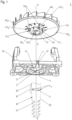
- a motor assembly 1 according to an exemplary embodiment of the present invention is shown in an exploded view.
- the motor assembly 1 comprises an impeller 30, and a motor holder 10 for connecting, in its mounted state, an electric motor with a gear unit of a kitchen appliance (as shown in Figure 3 ).
- the motor assembly 1 further comprises a rotor shaft 20, only an end portion of which is depicted in Figure 1 , the end portion comprising a worm 21 for driving the gear unit. While the impeller 30 and the motor holder 10 are shown, in Figure 1 , in perspective view, to illustrate an orifice O formed in the rotor shaft 20, said portion of the rotor shaft 20 is shown in a longitudinal cross section along its longitudinal centre axis being a designated axis X or rotation.
- the orifice O runs in radial direction with respect to the designated axis X of rotation, and in the embodiment depicted, it even is a through-hole radially crossing the rotor shaft 20.
- the orifice O widens radially outwards, which eases introduction of a tool.
- the rotor shaft 20 may comprise at least one further orifice (not visible in Figure 1 ) likewise running in radial direction, possibly being a further radial through-hole crossing the rotor shaft 20, which further through-hole may preferably cross the through-hole being the orifice O.
- the motor holder 10 forms a hole H configured to be run through by the rotor shaft 20 (as mentioned above, such hole is also referred to herein as "main" hole of the motor holder). Accordingly, the rotor shaft 20 is intended to run, in the mounted state of the motor holder, through the main hole H, such that the rotor shaft's designated axis X of rotation coincides with the centre axis X of the main hole H.
- a seat region R of the rotor shaft 20 is arranged within the main hole H of motor holder 10 (which thus encompasses said seat region R).
- a circumferential notch N formed in the rotor shaft serves to receive a circlip 42 for axially supporting a radially inner race 41 of a rolling-element bearing 40, as illustrated in Figure 2 .
- a radially outer race 43 of the rolling-element bearing 40 is arranged in a groove G the motor holder 10 forms at an enclosure of the main hole H.
- at least a portion of the radially inner race 41 is arranged, in the assembled state, within the main hole H.
- the motor holder 10 forms a passage P running through an annular enclosure 11 of the main hole, thereby providing a radial connection of the centre axis X of the main hole with a vicinity of the motor holder 10.
- a cavity C is formed in the enclosure 11 of the main hole H.
- the cavity C is adapted to receive a tip of a tool being inserted through the passage and running through the rotor shaft.
- the impeller 30 of the motor assembly 1 is configured to be penetrated by and fixed to the rotor shaft 20 and to thus be driven by the rotor shaft 20.
- the impeller comprises a sleeve 31 configured to at least partially be arranged, in the assembled state of the motor assembly 1, within the main hole H of the motor holder 10. In particular, in the assembled state, the sleeve 31 thus surrounds a portion of the seat region R the rotor shaft 20.
- the sleeve 31 forms four channels, of which only channels Ch 1 , Ch 2 , Ch 3 are visible, due to the perspective of Figure 1 . Respectively two of the channels are formed diametrically opposed to each other (with respect to the designated axis X of rotation), wherein the respective diameters run orthogonal to each other.
- the sleeve is 4-fold rotationally symmetric (i.e., rotationally symmetric of fourth order).
- a ring-shaped cover 32 which serves to protect the sleeve 31 during a process of assembling the impeller 30, covers the sleeve 31 in radial direction and at the sleeve's axial end facing the motor holder 10.
- the cover 32 is at least partially made of metal.
- the cover 32 forms four clearances, of which only clearances Cr 1 , Cr 2 are visible, due to the perspective of Figure 1 and which each overlap a respective one of the channels Ch 1 , Ch 2 , Ch 3 .
- the impeller 30 is fixed to the rotor shaft 20 such that at least two of the channels Ch 1 , Ch 2 , Ch 3 meet the at least one orifice O in the rotor shaft.
- a straight tool T such as a rod (in particular a shaft of a screw driver) is facilitated to run through the cover 32 and the sleeve 31 of the impeller into the orifice O.
- the impeller 30 comprises four guiding ribs 33 each extending radially from a vicinity of the sleeve 31 to a respective one of the channels Ch 1 , Ch 2 , Ch 3 .
- the impeller 30 When in the assembled state of the motor assembly said tool is being inserted radially from a vicinity of the motor holder 10 through the passage P thereof, and if the rotor shaft 20 with the impeller 30 fixed thereto is rotated in an appropriate rotational position (in which one of the channels Ch 1 , Ch 2 , Ch 3 superimposes the respective passage P and another one superimposes the cavity C), a respective one of said ribs 33 serves to guide a tip of the tool into said channel Ch 1 , Ch 2 , Ch 3 .
- the impeller 30 has marks M 1 , M 2 , M 3 , M 4 which each are positioned on a same diameter as a respective one of the channels Ch 1 , Ch 2 , Ch 3 . Accordingly, when the motor assembly is assembled and installed in a kitchen appliance such that - seen from a radial vicinity of the motor holder - the sleeve 31 is hidden, the marks M 1 , M 2 , M 3 , M 4 indicate a rotational position of the impeller 30. They thus enable a user to rotate the rotor shaft 20 with the impeller 30 so as to turn the at least one of the channels Ch 1 , Ch 2 , Ch 3 in line with the passage P of the motor holder 10.
- a straight tool can be inserted from a vicinity of the motor holder 10 through the passage P and into (or even through) the orifice O of the rotor shaft 20.
- the tool may then facilitate holding the rotor shaft 20 when a drive clutch is unscrewed therefrom and/or screwed thereon.
- the marks M 1 , M 2 , M 3 , M 4 each are configured as a respective groove running in axial direction (with respect to the designated axis X or rotation).
- the marks M 1 , M 2 , M 3 , M 4 also ease alignment of the channels Ch 1 , Ch 2 , Ch 3 with the orifice O of the rotor shaft 20 when the impeller 30 is fixed thereto during production of the electric motor.
- said marks M 1 , M 2 , M 3 , M 4 serve to hold the impeller 30 (e.g., with an appropriate holding means) in its position relative to the motor holder 10 when inserting said straight tool.
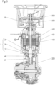
- Figure 2 shows, in a cross section along the designated axis X of rotation, a situation in which such tool T has been inserted from a vicinity of the motor holder 10 through the motor holder 10, the sleeve 31 (and its cover 32) of the impeller 30, and the rotor shaft 20.
- a section T P abuts the surfaces of the motor holder 10 and runs through the passage P formed therein, sections T Cr each run through a respective one of two diametrically opposed clearances in the cover 32 of the impeller's sleeve 31, two sections T Ch each run through a respective one of two diametrically opposed channels of the sleeve 31, a section T o runs through the orifice (being a through-hole) of the rotor shaft 20, and a section To (being a tip of the tool T) extends into the cavity C.
- FIG. 3 a portion of an exemplary embodiment of a kitchen appliance according to the present invention is shown in a sectional view.
- the kitchen appliance comprises an electric motor 100 with a stator 101 and a rotor 102, the rotor 102 mounted on a rotor shaft 20 of a motor assembly 1 according to an embodiment of the present invention.
- the electric motor 100 is connected to a gear unit 200 to be driven by a worm 21 formed at an end of the rotor shaft 20.
- the kitchen appliance is a kitchen machine comprising a blender attachment 300 which is configured to be driven by the electric motor 100 via the rotor shaft 20.
- the rotor shaft 20 is coupled to the blender attachment 300 by a drive clutch 50 engaging with a blender's (counter)clutch 350.
- the drive clutch 50 Due to high loads and vibrations often occurring during operation of such blender attachment 300, the drive clutch 50 is prone to abrasion and damages and therefore needs to be replaced from time to time. As explained above, the present invention facilitates such replacement in a convenient, safe and fast way, as it allows for an easy rotational fixation of the rotor shaft by introducing a straight tool. With such a rotational fixation, the drive clutch 50 can be easily screwed on or from the rotor shaft.
- the invention concerns a motor holder 10 for connecting, in a mounted stage, an electric motor 100 with a gear unit 200 of a kitchen appliance.
- the motor holder 10 forms a main hole H configured to be run through, in the mounted stage of the motor holder, by a rotor shaft 20 of the electric motor.
- the motor holder forms at least one passage P running through an enclosure 11 of the main hole H.
- the invention further concerns a rotor shaft 20 designated to run through a main hole H of a motor holder 10 for connecting an electric motor 100 with a gear unit 200 of a kitchen appliance. Therein, at least one orifice O is formed in the rotor shaft 20.
- the invention concerns a motor assembly 1 with a motor holder 10 and a rotor shaft 20, an electric motor 100, and a kitchen appliance.
Landscapes
- Engineering & Computer Science (AREA)
- Power Engineering (AREA)
- Manufacturing & Machinery (AREA)
- Connection Of Motors, Electrical Generators, Mechanical Devices, And The Like (AREA)
Abstract
Description
- The present invention concerns a motor holder of or for a kitchen appliance. The invention further concerns a rotor shaft of or for an electric motor of a kitchen appliance. Moreover, the invention concerns a motor assembly comprising a motor holder and a rotor shaft, an electric motor comprising such motor assembly, and a kitchen appliance comprising such electric motor.
- Electric kitchen appliances typically integrate at least one electric motor for driving a gear unit. Such gear unit may be designated to rotate at least one tool (such as a beater or a rotatable knife assembly) and/or a rotation system for a receptacle (for food to be processed) with increased output power.
- The electric motor may further be configured to rotate a further tool, such as a blender, for example. Therein, a rotor shaft's end may be adapted to directly transfer torque (i.e., without a gear unit) to the further tool. For this purpose, a drive clutch screwed on said end of the electric motor's rotor shaft may engage with a corresponding clutch fastened to an element (such as a tool shaft) combined to the further tool.
- Due to high loads and vibrations often occurring during operation of a kitchen appliance, in particular when rotating said further tool, such drive clutches wear off with working time of the kitchen appliance and, therefore, have to be replaced from time to time.
- It is an object of the present invention to simplify the replacement of a drive clutch of a kitchen appliance.
- The object is achieved by a motor holder according to
claim 1, a rotor shaft according to claim 3, a motor assembly according to claim 6, an electric motor according toclaim 11 and a kitchen appliance according to claim 12. Advantageous embodiments are disclosed in the dependent claims, the description and the figures. - A motor holder according to the present invention is intended for connecting, in a mounted state, an electric motor with a gear unit of a kitchen appliance. The motor holder forms a hole configured to be run through, in a mounted state of the motor holder, by a rotor shaft of the electric motor. That is, in said mounted state, the rotor shaft penetrates the motor holder by running through the hole. To prevent ambiguity, in the following, said hole is also denominated as "main hole" of the motor holder.
- The motor holder according to the present invention further forms a passage running through an enclosure of the main hole. With respect to a centre axis of the main hole, the passage preferably runs in radial direction. It may preferably provide a straight connection of the main hole, in particular of the centre axis thereof, with a vicinity of the motor holder.
- In particular, the passage thus facilitates access, through the motor holder, to the main hole and, therewith, in a mounted state, to the rotor shaft. Accordingly, the rotor shaft can be reached, even when assembled so as to run through the motor holder's main hole, with a tool such as a rod (e.g., a shaft of a screw driver) inserted into the passage. In particular, in combination with further means (such as an appropriate rotor shaft), the motor holder facilitates prohibiting a rotation of the rotor shaft in a secure and efficient manner, without blocking and thereby compromising other components (such as the gear unit or an impeller) of the kitchen appliance. As a consequence, a drive clutch screwed on the rotor shaft can be easily, safely and quickly replaced to maintain the functioning of the kitchen machine.
- The rotor shaft may preferably be carried by at least one rolling-element bearing which may be arranged in a groove the motor holder may form in the enclosure of the hole. In the mounted state, a centre axis of the hole preferably coincides with a designated axis of rotation of the rotor shaft. The enclosure of the main hole may in particular be ring-shaped.
- Radially outwards of the passage, in particular of the main hole's enclosure, the motor holder may further form an introductory path. Such introductory path may narrow towards the passage in the enclosure, and/or it may be shaped as a duct, which may be open in at least one axial direction (with respect to the centre axis of the main hole). Thereby, a secure guidance of a tool being introduced towards and into the passage is provided.
- According to advantageous embodiments, in a position diametrically opposed to the position, a cavity is formed in the enclosure of the main hole. Thereby, if the rotor shaft forms an appropriate through-hole, the tool may radially penetrate the rotor shaft and enter the cavity opposed to the passage. The cavity may then have a stabilising function for the tool and may thereby provide for a particularly reliable prohibition of a rotation of the rotor shaft during replacement of the drive clutch.
- Additionally or alternatively, said passage may be a first passage, and the motor holder may then form one or more further passage/s likewise running through the enclosure of the main hole, preferably providing a straight connection of the centre axis of the main hole with the vicinity of the motor holder.
- Such further passage may preferably be located in a position which compared to a position of the first passage is pivoted about the centre axis of the main hole, e.g., about an angle of 180° (in which case the respective further passage therefore is diametrically opposed to the first passage) and/or 90°.
- Such plurality of passages facilitates access to the rotor shaft from various sides of the kitchen appliance. Moreover, in case of diametrically opposed passages, analogously to what is explained above with respect to the cavity, if the rotor shaft forms an appropriate through-hole, the tool may radially penetrate the rotor shaft and thus run through both of the opposite passages. Thereby, the rotation of the rotor shaft can be prohibited in a particularly stable way.
- A rotor shaft according to the present invention is intended as a rotor shaft of or for an electric motor of a kitchen appliance. It is designated to run through a main hole of a motor holder (such as of a motor holder according to an embodiment of the present invention) connecting the electric motor with a gear unit of the kitchen appliance; a region of the rotor shaft which in such assembled state is arranged in the main hole of the motor holder (and thus encompassed by the motor holder) is further referred to herein as a "seat region". At least a portion of the seat region may be combined to or itself form a (radially inner) race of a rolling-element bearing configured to rotatably support the rotor shaft in the main hole of the motor holder.
- Therein, at least one orifice is formed in the rotor shaft according to the present invention.
- The orifice thus permits the rotor shaft to be at least partially pierced by a tool such as a rod inserted into the orifice. Thereby, a rotation of the rotor shaft (about its designated axis of rotation) can be prohibited even in an assembled state of the rotor shaft. In such an easily and securely realised secured state of the rotor shaft, a drive clutch can respectively be twisted off or screwed on the rotor shaft for replacement, without compromising other components (such as the gear unit) of the kitchen appliance.
- According to advantageous embodiments of a rotor shaft according to the present invention, the at least one orifice is formed in the rotor shaft's seat region or adjacent thereto (e.g., between the seat region and a worm the shaft may comprise for engaging with the gear unit).
- Preferably, an edge of the orifice is chamfered, such that the orifice widens in a direction radially outwards (with respect to the designated axis of rotation). Such embodiments ease the introduction of a tool into the orifice.
- With respect to a designated axis of rotation of the rotor shaft (which axis in the assembled state preferably coincides with a centre axis of the motor holder's main hole), the orifice preferably is a radial through-hole (thus, a diameter) running through the rotor shaft. Accordingly, a tool inserted into the orifice can be particularly stably held therein.
- A motor assembly according to the present invention comprises a motor holder and a rotor shaft, each according to a respective embodiment of the present invention. Therein, the rotor shaft is associated to the motor holder, i.e., it is intended to run, in an assembled state, through the main hole of the motor holder connecting an electric motor comprising the rotor shaft with a gear unit. Preferably, in such assembled state, the rotor shaft is carried by at least one rolling-element bearing the motor assembly may comprise, which rolling bearing may at least partially be arranged in a groove the motor holder advantageously forms at an enclosure of the main hole.
- In the designated position of the rotor shaft relative to the motor holder, the at least one orifice of the rotor shaft comprised by a motor assembly according to the present invention is adapted to meet, by rotation of the rotor shaft within the main hole and relative to the motor holder, the passage formed in the motor holder. In particular, the at least one orifice is advantageously formed in the seat region of the motor assembly's rotor shaft.
- The positions of the motor holder's passage and the rotor shaft's orifice thus allow a tool such as rod to be introduced through the motor holder's passage into the rotor shaft's orifice. Accordingly, in the assembled state of rotor shaft and motor holder, the rotor shaft's orifice can be accessed, from the vicinity of the motor holder, with the tool, so as to inhibit a rotation of the rotor shaft when replacing a drive clutch screwed thereon, without compromising other components.
- According to advantageous embodiments, the motor assembly further comprises an impeller with a sleeve fixed to the rotor shaft. Therein, the sleeve forms at least one channel which superimposes a respective one of the one or more orifice/s of the rotor shaft, i.e., which in radial direction (with respect to the designated axis of rotation) is positioned on a respective orifice.
- Preferably, the sleeve surrounds at least a portion of the rotor shaft's seat region. In an assembled state of the motor assembly, in which state the rotor shaft runs through said main hole of the motor holder in a designated position relative to the motor holder, the sleeve of such embodiment therefore is at least partially arranged within the motor holder's main hole, in particular radially between the motor holder and a portion of the rotor shaft.
- Such sleeve facilitates a secure fastening of the impeller to the rotor shaft, wherein the channel formed in the sleeve nonetheless maintains the above-mentioned accessibility of the rotor shaft by a tool, such as a rod, for inhibiting a rotation of the rotor shaft during replacement of a drive clutch.
- Preferably, the at least one channel runs in radial direction with respect to the designated axis of rotation.
- The sleeve may be at least partially covered by a ring-shaped cover having at least one clearance overlapping (in particular, being aligned with) the at least one channel formed by the sleeve.
- Such cover may serve to protect the impeller during a process of assembling the impeller. It may in particular partially or entirely be made of metal. With respect to the designated axis of rotation, it may extend on a circumference of the sleeve and/or on an axial end of the sleeve. Due to the clearance/s overlapping with the at least one channel formed in the sleeve, the accessibility of the rotor shaft through the channel/s is maintained.
- According to advantageous embodiments of the motor assembly according to the present invention, the impeller comprises at least one guiding rib extending radially (with respect to the designated axis of rotation) from a vicinity of the sleeve to the at least one channel. Such guiding rib may thus serve to guide a straight tool (e.g., a rod), when this is being inserted from the vicinity of the motor holder radially inwards towards the appropriately rotated rotor shaft, into the channel. In particular, the at least one guiding rib may preferably form a (smooth) sliding edge and/or a (smooth) sliding surface running from said vicinity of the sleeve into the respective channel thereof.
- Advantageously, the impeller has one or more mark/s on its perimeter. Such mark/s indicate/s a respective position, of the at least one channel formed in the impeller's sleeve, in circumferential direction. For instance, the mark/s may be arranged on a same radius as a respective one of the at least one channel.
- By such mark/s, a person intending to replace the drive clutch is supported in appropriately rotating the impeller and, therewith, the rotor shaft, such that the at least one passage formed in the motor holder, the at least one channel formed in the impeller's sleeve and the at least one orifice of the rotor shaft are arranged on a common (preferably radial) line and thus allow introduction of a tool from a circumference of the motor holder into (in respective embodiments even through) the at least one orifice of the rotor shaft, whereby a rotation of the rotor shaft relative to the motor holder can be inhibited.
- In particular, the at least one mark may comprise at least one groove running in axial direction (with respect to the designated axis of rotation). Such groove simplifies catching, rotating and holding the impeller (and therewith, the rotor shaft) in an appropriate rotational position.
- According to advantageous embodiments, the impeller is rotationally symmetric of finite order, such as of order 2, or of
order 4, or of order 6, for example. In particular, it may comprise various channels which are uniformly distributed in circumferential direction of the impeller, and in respective embodiments comprising various marks, various guiding ribs and/or a cover with various clearances, the same may respectively hold for the marks, guiding ribs and/or clearances. Such embodiments eliminate balance disturbances in the electric motor, and they further provide for easily aligning the rotor shaft's orifice with the motor holder's passage when a tool is desired to be introduced to inhibit rotation of the rotor shaft. - An electric motor according to the present invention comprises a motor assembly according to an embodiment of the present invention, a stator, and a rotor fastened to the rotor shaft of the motor assembly.
- A kitchen appliance according to the present invention comprises an electric motor according to an embodiment of the present invention, and a gear unit configured to be driven by the electric motor. In particular, the motor holder of the motor assembly comprised by the electric motor connects the latter to the gear unit. The kitchen appliance may in particular be a kitchen machine, such as an electric food processor or a multi-purpose kitchen appliance. Such kitchen machine may comprise a blender attachment configured to be driven by the rotor shaft of the motor assembly comprised by the electric motor. Therein, the blender attachment may be coupled to the rotor shaft by means of a coupling comprising a drive clutch screwed on the rotor shaft, and a blender's (counter)clutch engaging with the drive clutch.
- In what follows, preferred embodiments of the present invention are explained with respect to the accompanying drawings. As is to be understood, the various elements and components are depicted as examples only, and they may be facultative and/or combined in a manner different than that depicted. Reference signs for related elements are used comprehensively and not defined again for each figure.
- Shown is schematically in
- Fig. 1:
- an exploded view of a motor assembly according to an exemplary embodiment of the present invention;
- Fig. 2:
- a cross section of a motor assembly according to an exemplary embodiment of the present invention being pierced by a tool; and
- Fig. 3:
- a portion of an exemplary embodiment of a kitchen appliance according to the present invention in a cross-sectional view.
- In
Figure 1 , amotor assembly 1 according to an exemplary embodiment of the present invention is shown in an exploded view. Themotor assembly 1 comprises animpeller 30, and amotor holder 10 for connecting, in its mounted state, an electric motor with a gear unit of a kitchen appliance (as shown inFigure 3 ). Themotor assembly 1 further comprises arotor shaft 20, only an end portion of which is depicted inFigure 1 , the end portion comprising aworm 21 for driving the gear unit. While theimpeller 30 and themotor holder 10 are shown, inFigure 1 , in perspective view, to illustrate an orifice O formed in therotor shaft 20, said portion of therotor shaft 20 is shown in a longitudinal cross section along its longitudinal centre axis being a designated axis X or rotation. In particular, as thereby apparent fromFigure 1 , the orifice O runs in radial direction with respect to the designated axis X of rotation, and in the embodiment depicted, it even is a through-hole radially crossing therotor shaft 20. By chamfered regions Ca in its edge, the orifice O widens radially outwards, which eases introduction of a tool. - The
rotor shaft 20 may comprise at least one further orifice (not visible inFigure 1 ) likewise running in radial direction, possibly being a further radial through-hole crossing therotor shaft 20, which further through-hole may preferably cross the through-hole being the orifice O. - The
motor holder 10 forms a hole H configured to be run through by the rotor shaft 20 (as mentioned above, such hole is also referred to herein as "main" hole of the motor holder). Accordingly, therotor shaft 20 is intended to run, in the mounted state of the motor holder, through the main hole H, such that the rotor shaft's designated axis X of rotation coincides with the centre axis X of the main hole H. In a such assembled state (illustrated inFigure 2 ), a seat region R of therotor shaft 20 is arranged within the main hole H of motor holder 10 (which thus encompasses said seat region R). A circumferential notch N formed in the rotor shaft serves to receive acirclip 42 for axially supporting a radiallyinner race 41 of a rolling-element bearing 40, as illustrated inFigure 2 . Therein, in the embodiment depicted inFigure 2 , a radiallyouter race 43 of the rolling-element bearing 40 is arranged in a groove G themotor holder 10 forms at an enclosure of the main hole H. In particular, at least a portion of the radiallyinner race 41 is arranged, in the assembled state, within the main hole H. - As further seen in
Figure 1 , themotor holder 10 forms a passage P running through anannular enclosure 11 of the main hole, thereby providing a radial connection of the centre axis X of the main hole with a vicinity of themotor holder 10. Radially outwards of the passage P, in particular of the main hole'senclosure 11, themotor holder 10 forms an introductory path I which is shaped as a duct which is open in one axial direction. - Moreover, in the embodiment depicted, diametrically opposed to the passage P with respect to the centre axis X, a cavity C is formed in the
enclosure 11 of the main hole H. As seen inFigure 2 , the cavity C is adapted to receive a tip of a tool being inserted through the passage and running through the rotor shaft. - The
impeller 30 of themotor assembly 1 is configured to be penetrated by and fixed to therotor shaft 20 and to thus be driven by therotor shaft 20. As further seen inFigure 1 , the impeller comprises asleeve 31 configured to at least partially be arranged, in the assembled state of themotor assembly 1, within the main hole H of themotor holder 10. In particular, in the assembled state, thesleeve 31 thus surrounds a portion of the seat region R therotor shaft 20. - In the embodiment shown in
Figure 1 , thesleeve 31 forms four channels, of which only channels Ch1, Ch2, Ch3 are visible, due to the perspective ofFigure 1 . Respectively two of the channels are formed diametrically opposed to each other (with respect to the designated axis X of rotation), wherein the respective diameters run orthogonal to each other. In particular, the sleeve is 4-fold rotationally symmetric (i.e., rotationally symmetric of fourth order). It is partially covered by a ring-shapedcover 32; in particular, saidcover 32, which serves to protect thesleeve 31 during a process of assembling theimpeller 30, covers thesleeve 31 in radial direction and at the sleeve's axial end facing themotor holder 10. Advantageously, thecover 32 is at least partially made of metal. - The
cover 32 forms four clearances, of which only clearances Cr1, Cr2 are visible, due to the perspective ofFigure 1 and which each overlap a respective one of the channels Ch1, Ch2, Ch3. - As can be taken from
Figure 2 , theimpeller 30 is fixed to therotor shaft 20 such that at least two of the channels Ch1, Ch2, Ch3 meet the at least one orifice O in the rotor shaft. As a consequence, a straight tool T such as a rod (in particular a shaft of a screw driver) is facilitated to run through thecover 32 and thesleeve 31 of the impeller into the orifice O. - As further seen in
Figure 1 , theimpeller 30 comprises four guidingribs 33 each extending radially from a vicinity of thesleeve 31 to a respective one of the channels Ch1, Ch2, Ch3. When in the assembled state of the motor assembly said tool is being inserted radially from a vicinity of themotor holder 10 through the passage P thereof, and if therotor shaft 20 with theimpeller 30 fixed thereto is rotated in an appropriate rotational position (in which one of the channels Ch1, Ch2, Ch3 superimposes the respective passage P and another one superimposes the cavity C), a respective one of saidribs 33 serves to guide a tip of the tool into said channel Ch1, Ch2, Ch3. - In its periphery, the
impeller 30 has marks M1, M2, M3, M4 which each are positioned on a same diameter as a respective one of the channels Ch1, Ch2, Ch3. Accordingly, when the motor assembly is assembled and installed in a kitchen appliance such that - seen from a radial vicinity of the motor holder - thesleeve 31 is hidden, the marks M1, M2, M3, M4 indicate a rotational position of theimpeller 30. They thus enable a user to rotate therotor shaft 20 with theimpeller 30 so as to turn the at least one of the channels Ch1, Ch2, Ch3 in line with the passage P of themotor holder 10. In such position of therotor shaft 20 and themotor holder 10 relative to each other, a straight tool can be inserted from a vicinity of themotor holder 10 through the passage P and into (or even through) the orifice O of therotor shaft 20. The tool may then facilitate holding therotor shaft 20 when a drive clutch is unscrewed therefrom and/or screwed thereon. - In the embodiment shown in
Figure 1 , the marks M1, M2, M3, M4 each are configured as a respective groove running in axial direction (with respect to the designated axis X or rotation). Thereby, the marks M1, M2, M3, M4 also ease alignment of the channels Ch1, Ch2, Ch3 with the orifice O of therotor shaft 20 when theimpeller 30 is fixed thereto during production of the electric motor. Moreover, said marks M1, M2, M3, M4 serve to hold the impeller 30 (e.g., with an appropriate holding means) in its position relative to themotor holder 10 when inserting said straight tool. - As mentioned above,
Figure 2 shows, in a cross section along the designated axis X of rotation, a situation in which such tool T has been inserted from a vicinity of themotor holder 10 through themotor holder 10, the sleeve 31 (and its cover 32) of theimpeller 30, and therotor shaft 20. Accordingly, as indicated inFigure 2 , a section TP abuts the surfaces of themotor holder 10 and runs through the passage P formed therein, sections TCr each run through a respective one of two diametrically opposed clearances in thecover 32 of the impeller'ssleeve 31, two sections TCh each run through a respective one of two diametrically opposed channels of thesleeve 31, a section To runs through the orifice (being a through-hole) of therotor shaft 20, and a section To (being a tip of the tool T) extends into the cavity C. Thereby, a rotation of therotor shaft 20 relative to the motor holder 10 (and thereby, to the gear unit the motor holder may be mounted to) is comfortably and reliably inhibited, such that a drive clutch screwed on the rotor shaft (not shown inFigure 2 ) can be easily and quickly replaced without compromising other component of the kitchen appliance. - In
Figure 3 , a portion of an exemplary embodiment of a kitchen appliance according to the present invention is shown in a sectional view. The kitchen appliance comprises anelectric motor 100 with astator 101 and arotor 102, therotor 102 mounted on arotor shaft 20 of amotor assembly 1 according to an embodiment of the present invention. By means of amotor holder 10 of saidmotor assembly 1, theelectric motor 100 is connected to agear unit 200 to be driven by aworm 21 formed at an end of therotor shaft 20. - In the embodiment shown in
Figure 3 , the kitchen appliance is a kitchen machine comprising ablender attachment 300 which is configured to be driven by theelectric motor 100 via therotor shaft 20. To this end, therotor shaft 20 is coupled to theblender attachment 300 by a drive clutch 50 engaging with a blender's (counter)clutch 350. - Due to high loads and vibrations often occurring during operation of
such blender attachment 300, thedrive clutch 50 is prone to abrasion and damages and therefore needs to be replaced from time to time. As explained above, the present invention facilitates such replacement in a convenient, safe and fast way, as it allows for an easy rotational fixation of the rotor shaft by introducing a straight tool. With such a rotational fixation, the drive clutch 50 can be easily screwed on or from the rotor shaft. - The invention concerns a
motor holder 10 for connecting, in a mounted stage, anelectric motor 100 with agear unit 200 of a kitchen appliance. Themotor holder 10 forms a main hole H configured to be run through, in the mounted stage of the motor holder, by arotor shaft 20 of the electric motor. Moreover, the motor holder forms at least one passage P running through anenclosure 11 of the main hole H. - The invention further concerns a
rotor shaft 20 designated to run through a main hole H of amotor holder 10 for connecting anelectric motor 100 with agear unit 200 of a kitchen appliance. Therein, at least one orifice O is formed in therotor shaft 20. - Moreover, the invention concerns a
motor assembly 1 with amotor holder 10 and arotor shaft 20, anelectric motor 100, and a kitchen appliance. -
- 1
- motor assembly
- 10
- motor holder
- 11
- enclosure of main hole
- 20
- rotor shaft
- 21
- worm
- 30
- impeller
- 31
- sleeve
- 32
- cover
- 33
- guiding rib
- 40
- rolling-element bearing
- 41
- radial inner race of rolling-
element bearing 40 - 42
- circlip
- 50
- drive clutch
- 100
- electric motor
- 101
- stator
- 102
- rotor
- 200
- gear unit
- 300
- blender attachment
- 350
- blender's clutch
- C
- cavity
- Ca
- chamfered region
- Ch1, Ch2, Ch3
- channel
- Cr1, Cr2
- clearance
- G
- groove
- H
- main hole
- I
- introductory path
- M1, M2, M3, M4
- mark
- N
- notch
- O
- orifice
- P
- passage
- R
- seat region
- T
- tool
- TC, TCh, TCr, TO, TP
- sections of tool T
- X
- centre axis of main hole H; designated axis of rotation
Claims (12)
- Motor holder (10) for connecting, in a mounted stage, an electric motor (100) with a gear unit (200) of a kitchen appliance, the motor holder (10) forming a main hole (H) configured to be run through, in the mounted stage of the motor holder, by a rotor shaft (20) of the electric motor,
wherein the motor holder (10) further forms a passage (P) running through an enclosure (11) of the main hole (H). - Motor holder according to claim 1, wherein in a position which with respect to a centre axis (X) of the hole (H) is diametrically opposed to the passage (P), a cavity (C) is formed in the enclosure (11) of the main hole (H).
- Rotor shaft (20) of or for an electric motor (100) of or for a kitchen appliance, the rotor shaft (20) designated to run through a main hole (H) of a motor holder (10) connecting the electric motor (100) with a gear unit (200) of the kitchen appliance, wherein at least one orifice (O) is formed in the rotor shaft (20).
- Rotor shaft according to claim 3, wherein the at least one orifice (O) is formed in a seat region (R) or adjacent to a seat region (R) of the rotor shaft (20), the seat region (R) designated to be arranged in said main hole (H) of the motor holder (10).
- Rotor shaft according to one of claims 3 or 4, wherein with respect to a designated axis (X) of rotation, the orifice (O) is a radial through-hole running through the rotor shaft (20).
- Motor assembly (1) comprising- a motor holder (10) according to one of claims 1 or 2, and- an associated rotor shaft (20) according to one of claims 3 to 5,wherein the at least one orifice (O) is adapted to meet, by rotation of the rotor shaft (20) in the motor holder's main hole (H) and relative to the motor holder (10), the passage (P) formed in the motor holder (10).
- Motor assembly (1) according to claim 6, further comprising an impeller (30) with a sleeve (31) fixed to the rotor shaft (20), the sleeve (31) forming at least one channel (Ch1, Ch2, Ch3) superimposing the at least one orifice (O) of the rotor shaft (20).
- Motor assembly according to claim 7, wherein the impeller comprises a ring-shaped cover (32) covering at least a portion of the sleeve (31), wherein the cover (32) has at least one clearance (Cr1, Cr2) overlapping the at least one channel (Ch1, Ch2, Ch3).
- Motor assembly according to one of claims 7 or 8, wherein the impeller (30) comprises at least one guiding rib (33) extending radially from a vicinity of the sleeve to the at least one channel (Ch1, Ch2, Ch3).
- Motor assembly according to one of claims 7 to 9, wherein the impeller (30) has one or more mark/s (M1, M2, M3, M4) on its perimeter.
- Electric motor (100) comprising a stator (101), a rotor (102), and a motor assembly (1) according to one of claims 6 to 10, the rotor (102) being fastened to the rotor shaft (20) of the motor assembly (1).
- Kitchen appliance comprising an electric motor (100) according to claim 11, and a gear unit (200) configured to be driven by the electric motor (100).
Priority Applications (1)
| Application Number | Priority Date | Filing Date | Title |
|---|---|---|---|
| EP22216304.0A EP4391325A1 (en) | 2022-12-23 | 2022-12-23 | Motor holder and rotor shaft for or of a kitchen appliance |
Applications Claiming Priority (1)
| Application Number | Priority Date | Filing Date | Title |
|---|---|---|---|
| EP22216304.0A EP4391325A1 (en) | 2022-12-23 | 2022-12-23 | Motor holder and rotor shaft for or of a kitchen appliance |
Publications (1)
| Publication Number | Publication Date |
|---|---|
| EP4391325A1 true EP4391325A1 (en) | 2024-06-26 |
Family
ID=84602213
Family Applications (1)
| Application Number | Title | Priority Date | Filing Date |
|---|---|---|---|
| EP22216304.0A Pending EP4391325A1 (en) | 2022-12-23 | 2022-12-23 | Motor holder and rotor shaft for or of a kitchen appliance |
Country Status (1)
| Country | Link |
|---|---|
| EP (1) | EP4391325A1 (en) |
Citations (3)
| Publication number | Priority date | Publication date | Assignee | Title |
|---|---|---|---|---|
| CN202281289U (en) * | 2011-11-02 | 2012-06-20 | 冯兆初 | Easy disassembly and washing wind wheel structure of range hood |
| US20150180290A1 (en) * | 2013-12-24 | 2015-06-25 | Sunonwealth Electric Machine Industry Co., Ltd. | Motor of a Ceiling Fan |
| CN107516980B (en) * | 2017-09-08 | 2019-10-01 | 珠海格力电器股份有限公司 | Disassembly and assembly tooling for working parts with interference fit with shaft |
-
2022
- 2022-12-23 EP EP22216304.0A patent/EP4391325A1/en active Pending
Patent Citations (3)
| Publication number | Priority date | Publication date | Assignee | Title |
|---|---|---|---|---|
| CN202281289U (en) * | 2011-11-02 | 2012-06-20 | 冯兆初 | Easy disassembly and washing wind wheel structure of range hood |
| US20150180290A1 (en) * | 2013-12-24 | 2015-06-25 | Sunonwealth Electric Machine Industry Co., Ltd. | Motor of a Ceiling Fan |
| CN107516980B (en) * | 2017-09-08 | 2019-10-01 | 珠海格力电器股份有限公司 | Disassembly and assembly tooling for working parts with interference fit with shaft |
Similar Documents
| Publication | Publication Date | Title |
|---|---|---|
| CA2818879C (en) | Electric machine, in particular of a pump unit | |
| US20040211065A1 (en) | System for mounting a first member in a hollow second member | |
| US6291920B1 (en) | Motor counter weight attachment | |
| EP0274874A2 (en) | Planet gear carrier assembly | |
| RU2672353C2 (en) | Pump device with sliding bearing system | |
| US10088033B2 (en) | Drive mechanism for a spin test rig | |
| JP2018537188A5 (en) | ||
| US11209071B2 (en) | Planetary transmission | |
| WO1998015742A1 (en) | Mounting device | |
| US10527045B2 (en) | Motor of a ceiling fan, the motor having an axially spaced bearing, a radially spaced bearing and a third bearing | |
| EP3256707B1 (en) | Bearings for a turbocharger | |
| US20190149012A1 (en) | Direct-drive electric motor arrangement | |
| JP3685115B2 (en) | Planetary gear set | |
| AU2018320579A1 (en) | Covering system for wheelset shafts of rail vehicles | |
| ZA201004452B (en) | Rotor for permanent magnet electric machine | |
| KR20160013793A (en) | Car axle mounting structure of grass eliminator rotor | |
| WO2018043338A1 (en) | Rotary machine | |
| US20240191747A1 (en) | Bearing housing assembly and ring configured to provide multiple modes of operation | |
| US20200366143A1 (en) | Rotor structure for electric motor | |
| US20110021120A1 (en) | Hand-held machine tool, in particular hand-guided grinding machine | |
| US5853248A (en) | Radial thrust bearing | |
| US11498236B2 (en) | Slicing machine with motor tower and directly driven circular blade | |
| US20200038139A1 (en) | Dental treatment instrument for operating a rotational tool | |
| EP1630281A2 (en) | Refiner plate | |
| GB1566735A (en) | Guard device for rotry shaft |
Legal Events
| Date | Code | Title | Description |
|---|---|---|---|
| PUAI | Public reference made under article 153(3) epc to a published international application that has entered the european phase |
Free format text: ORIGINAL CODE: 0009012 |
|
| STAA | Information on the status of an ep patent application or granted ep patent |
Free format text: STATUS: THE APPLICATION HAS BEEN PUBLISHED |
|
| AK | Designated contracting states |
Kind code of ref document: A1 Designated state(s): AL AT BE BG CH CY CZ DE DK EE ES FI FR GB GR HR HU IE IS IT LI LT LU LV MC ME MK MT NL NO PL PT RO RS SE SI SK SM TR |
|
| STAA | Information on the status of an ep patent application or granted ep patent |
Free format text: STATUS: REQUEST FOR EXAMINATION WAS MADE |
|
| 17P | Request for examination filed |
Effective date: 20250102 |
|
| STAA | Information on the status of an ep patent application or granted ep patent |
Free format text: STATUS: EXAMINATION IS IN PROGRESS |
|
| 17Q | First examination report despatched |
Effective date: 20250402 |