EP4391318A1 - Six-pole 54-slot flat wire motor three-branch balancing winding and use method therefor - Google Patents
Six-pole 54-slot flat wire motor three-branch balancing winding and use method therefor Download PDFInfo
- Publication number
- EP4391318A1 EP4391318A1 EP23856316.7A EP23856316A EP4391318A1 EP 4391318 A1 EP4391318 A1 EP 4391318A1 EP 23856316 A EP23856316 A EP 23856316A EP 4391318 A1 EP4391318 A1 EP 4391318A1
- Authority
- EP
- European Patent Office
- Prior art keywords
- slot
- layer
- winding
- branch
- phase
- Prior art date
- Legal status (The legal status is an assumption and is not a legal conclusion. Google has not performed a legal analysis and makes no representation as to the accuracy of the status listed.)
- Granted
Links
Images





Classifications
-
- H—ELECTRICITY
- H02—GENERATION; CONVERSION OR DISTRIBUTION OF ELECTRIC POWER
- H02K—DYNAMO-ELECTRIC MACHINES
- H02K3/00—Details of windings
- H02K3/04—Windings characterised by the conductor shape, form or construction, e.g. with bar conductors
- H02K3/28—Layout of windings or of connections between windings
-
- H—ELECTRICITY
- H02—GENERATION; CONVERSION OR DISTRIBUTION OF ELECTRIC POWER
- H02K—DYNAMO-ELECTRIC MACHINES
- H02K3/00—Details of windings
- H02K3/04—Windings characterised by the conductor shape, form or construction, e.g. with bar conductors
-
- H—ELECTRICITY
- H02—GENERATION; CONVERSION OR DISTRIBUTION OF ELECTRIC POWER
- H02K—DYNAMO-ELECTRIC MACHINES
- H02K3/00—Details of windings
- H02K3/04—Windings characterised by the conductor shape, form or construction, e.g. with bar conductors
- H02K3/12—Windings characterised by the conductor shape, form or construction, e.g. with bar conductors arranged in slots
-
- H—ELECTRICITY
- H02—GENERATION; CONVERSION OR DISTRIBUTION OF ELECTRIC POWER
- H02K—DYNAMO-ELECTRIC MACHINES
- H02K3/00—Details of windings
- H02K3/46—Fastening of windings on the stator or rotor structure
- H02K3/48—Fastening of windings on the stator or rotor structure in slots
-
- H—ELECTRICITY
- H02—GENERATION; CONVERSION OR DISTRIBUTION OF ELECTRIC POWER
- H02K—DYNAMO-ELECTRIC MACHINES
- H02K3/00—Details of windings
- H02K3/46—Fastening of windings on the stator or rotor structure
- H02K3/50—Fastening of winding heads, equalising connectors, or connections thereto
-
- Y—GENERAL TAGGING OF NEW TECHNOLOGICAL DEVELOPMENTS; GENERAL TAGGING OF CROSS-SECTIONAL TECHNOLOGIES SPANNING OVER SEVERAL SECTIONS OF THE IPC; TECHNICAL SUBJECTS COVERED BY FORMER USPC CROSS-REFERENCE ART COLLECTIONS [XRACs] AND DIGESTS
- Y02—TECHNOLOGIES OR APPLICATIONS FOR MITIGATION OR ADAPTATION AGAINST CLIMATE CHANGE
- Y02T—CLIMATE CHANGE MITIGATION TECHNOLOGIES RELATED TO TRANSPORTATION
- Y02T10/00—Road transport of goods or passengers
- Y02T10/60—Other road transportation technologies with climate change mitigation effect
- Y02T10/64—Electric machine technologies in electromobility
Definitions
- the present application relates to the technical field of components of windings of the motor distributed in slots, and in particular to a three-branch balanced winding of a six-pole, fifty-four-slot flat copper wire motor, and a method.
- Flat copper wire drive motors used in electric vehicles generally suffer from unbalanced current in each phase winding branch, many special-shaped wires, and poor mass production processability.
- the frequency of the power supply gradually increases, due to potential imbalance between the same-phase branches, the current between the parallel branches will gradually be unevenly distributed, and there will be circulating current between the branches, which will eventually lead to uneven heating of the inner and outer armature winding branches, thereby damaging the insulation system of the motor.
- Flat copper wire motors have multiple parallel branches, resulting in a complex structure of bridging wires, star point wires, and power supply lead wires connected to the end of the flat copper wires, which does not meet the requirements of automated wire insertion processes.
- the present application provides a three-branch balanced winding of a six-pole, fifty-four-slot flat copper wire motor, and a method.
- a three-branch balanced winding of a six-pole, fifty-four-slot flat copper wire motor includes:
- the three-phase flat copper wire winding is a six-layer winding, and each phase winding is composed of three branches connected in parallel; a connection sequence of each parallel branch is configured as follows: entering from a first layer L1 of the iron core slot; passing through a second layer L2, a third layer L3, a fourth layer L4, a fifth layer L5, and a sixth layer L6 along a forward direction in sequence; passing through the sixth layer L6, the fifth layer L5, the fourth layer L4, the third layer L3, the second layer L2, the first layer L1 along a reverse direction in sequence; passing through the first layer L1, the second layer L2, the third layer L3, the fourth layer L4, the fifth layer L5, and the sixth layer L6 along the forward direction; passing through the sixth layer L6, the fifth layer L5, the fourth layer L4, the third layer L3, the second layer L2, the first layer L1 along the reverse direction; passing through the first layer L1, the second layer L2, the third layer L3, the fourth layer L4, the fifth layer L5, and the sixth layer L6 along the forward direction; passing
- the U-phase power wire, the V-phase power wire and the W-phase of the three-phase flat copper wire winding is configured to adopt a Y-connection manner (as shown in the FIG. 7 ) or a delta connection manner (as shown in the FIG. 9 ); and the three-phase flat copper wire winding is configured to adopt a short span with a span Y of eight, a full span with a span Y of nine, or a long span with a span Y of ten.
- a method of using the three-branch balanced winding of the six-pole fifty-four-slot flat copper wire motor where the method is implemented in sequence as follows:
- the present application has the following beneficial effects.
- the names of the components represented by the reference numbers are as follows: 1, welding end of the winding end; 2, straight portion of the wire in the iron core and the iron core slot; 3, power lead end; 4, I-pin wire and star point lead wire of the power lead wire (when adopting the Y-connection manner) at the first layer in the iron core slot; 5, U-pin wire at the first layer in the iron core slot; 6, U-pin wire at the second and third layers in the iron core slot; 7, U-pin wire at the fourth and fifth layers in the iron core slot; 8, U-pin wire at the sixth layer in the iron core slot.
- a three-branch balanced winding of a six-pole, fifty-four-slot flat copper wire motor with a short range of Y 8, adopts the Y-connection manner, and a number a of parallel branches is 3.
- the winding connection structure is as shown in FIG. 1 to FIG. 8 , and the specific structure is as follows.
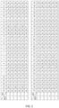
- the winding expansion diagram shows a six-layer flat copper wire winding, that is, there are 6 flat copper wires in each slot number.
- the number of flat wire layers from the bottom of the slot to the opening of the slot is 1, 2, 3, 4, 5, and 6, which is as shown in FIG. 1 .
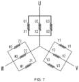
- the winding adopts the Y-connection manner, the number a of parallel branches is 3, and each phase winding is composed of three branches connected in parallel, as shown in FIG. 7 .
- the U-phase winding is composed of a branch 1 (U1-X1), a branch 2 (U2-X2) and a branch 3 (U3-X3)
- the V-phase winding is composed of a branch 1 (V1-Y1), a branch 2 (V2-Y2) and a branch 3 (V3-Y3)
- the W-phase winding is composed of a branch 1 (W1-Z1), a branch 2 (W2-Z2) and a branch 3 (W3-Z3).
- the branch 1 of the U-phase winding namely a first end U1 of U1-X1, enters from the first layer L1 of a slot 1 of the winding along a current flow direction, finally flows out from a first layer L1 of a slot 12, and the winding connection sequence is: L1 of a slot 1 ⁇ L2 of a slot 9 ⁇ L3 of a slot 19 ⁇ L4 of a slot 27 ⁇ L5 of a slot 37 ⁇ L6 of a slot 45 ⁇ L6 of a slot 54 ⁇ L5 of a slot 46 ⁇ L4 of a slot 36 ⁇ L3 of a slot 28 ⁇ L2 of a slot 18 ⁇ L1 of a slot 10 ⁇ L1 of a slot 2 ⁇ L2 of a slot 10 ⁇ L3 of a slot 20 ⁇ L4 of a slot 28 ⁇ L5 of a slot 38 ⁇ L6 of a slot 46 ⁇ L6 of a slot 1 ⁇ L5 of a slot 47 ⁇ L4 of a slot 37 ⁇ L3 of a slot 29 ⁇ L2 of a slot 19
- the branch 2 of the U-phase winding namely a first end U2 of U2-X2, enters from the first layer L1 of a slot 19 of the winding along a current flow direction, finally flows out from a first layer L1 of a slot 30, and the winding connection sequence is: L1 of a slot 19 ⁇ L2 of a slot 27 ⁇ L3 of a slot 37 ⁇ L4 of a slot 45 ⁇ L5 of a slot 1 ⁇ L6 of a slot 9 ⁇ L6 of a slot 18 ⁇ L5 of a slot 10 ⁇ L4 of a slot 54 ⁇ L3 of a slot 46 ⁇ L2 of a slot 36 ⁇ L1 of a slot 28 ⁇ L1 of a slot 20 ⁇ L2 of a slot 28 ⁇ L3 of a slot 38 ⁇ L4 of a slot 46 ⁇ L5 of a slot 2 ⁇ L6 of a slot 10 ⁇ L6 of a slot 19 ⁇ L5 of a slot 11 ⁇ L4 of a slot 1 ⁇ L3 of a slot 47 ⁇ L2 of a slot 37 ⁇
- the branch 3 of the U-phase winding namely a first end U1 of U3-X3, enters from the first layer L1 of a slot 37 of the winding along a current flow direction, finally flows out from a first layer L1 of a slot 48, and the winding connection sequence is: L1 of a slot 37 ⁇ L2 of a slot 45 ⁇ L3 of a slot 1 ⁇ L4 of a slot 9 ⁇ L5 of a slot 19 ⁇ L6 of a slot 27 ⁇ L6 of a slot 36 ⁇ L5 of a slot 28 ⁇ L4 of a slot 18 ⁇ L3 of a slot 10 ⁇ L2 of a slot 54 ⁇ L1 of a slot 46 ⁇ L1 of a slot 38 ⁇ L2 of a slot 46 ⁇ L3 of a slot 2 ⁇ L4 of a slot 10 ⁇ L5 of a slot 20 ⁇ L6 of a slot 28 ⁇ L6 of a slot 37 ⁇ L5 of a slot 29 ⁇ L4 of a slot 19 ⁇ L3 of a slot 11 ⁇ L2 of a slot
- V-phase winding and U-phase winding branches are connected in the same way, except that the starting slot is different, that is, a branch 1 (V1-Y1) of the V-phase winding enters from the first layer L1 of a slot 7 of the winding along a current flow direction and finally flows out from a first layer L1 of a slot 18, a branch 2 (V2-Y2) of the V-phase winding enters from the first layer L1 of a slot 25 of the winding along a current flow direction and finally flows out from a first layer L1 of a slot 36, a branch 3 (V3-Y3) of the V-phase winding enters from the first layer L1 of a slot 43 of the winding along a current flow direction and finally flows out from a first layer L1 of a slot 54.
- the detailed connection sequence of the three branches is as shown in FIG. 8 .
- the branch 1 of the V-phase winding namely a first end V1 of V1-Y1 enters from the first layer L1 of a slot 7 of the winding along a current flow direction, finally flows out from a first layer L1 of a slot 18, and the winding connection sequence is: L1 of a slot 7 ⁇ L2 of a slot 15 ⁇ L3 of a slot 25 ⁇ L4 of a slot 33 ⁇ L5 of a slot 43 ⁇ L6 of a slot 51 ⁇ L6 of a slot 6 ⁇ L5 of a slot 52 ⁇ L4 of a slot 42 ⁇ L3 of a slot 34 ⁇ L2 of a slot 24 ⁇ L1 of a slot 16 ⁇ L1 of a slot 8 ⁇ L2 of a slot 16 ⁇ L3 of a slot 26 ⁇ L4 of a slot 34 ⁇ L5 of a slot 44 ⁇ L6 of a slot 52 ⁇ L6 of a slot 7 ⁇ L5 of a slot 53 ⁇ L4 of a slot 43 ⁇ L3 of a slot 35 ⁇ L2 of a slot 25
- the branch 2 of the V-phase winding namely a first end V2 of V2-Y2 enters from the first layer L1 of a slot 25 of the winding along a current flow direction, finally flows out from a first layer L1 of a slot 36, and the winding connection sequence is: L1 of a slot 25 ⁇ L2 of a slot 33 ⁇ L3 of a slot 43 ⁇ L4 of a slot 51 ⁇ L5 of a slot 7 ⁇ L6 of a slot 15 ⁇ L6 of a slot 24 ⁇ L5 of a slot 16 ⁇ L4 of a slot 6 ⁇ L3 of a slot 52 ⁇ L2 of a slot 42 ⁇ L1 of a slot 34 ⁇ L1 of a slot 26 ⁇ L2 of a slot 34 ⁇ L3 of a slot 44 ⁇ L4 of a slot 52 ⁇ L5 of a slot 8 ⁇ L6 of a slot 16 ⁇ L6 of a slot 25 ⁇ L5 of a slot 17 ⁇ L4 of a slot 7 ⁇ L3 of a slot 53 ⁇ L2 of a slot 43
- the branch 3 of the V-phase winding namely a first end V3 of V3-Y3, enters from the first layer L1 of a slot 43 of the winding along a current flow direction, finally flows out from a first layer L1 of a slot 54, and the winding connection sequence is: L1 of a slot 43 ⁇ L2 of a slot 51 ⁇ L3 of a slot 7 ⁇ L4 of a slot 15 ⁇ L5 of a slot 25 ⁇ L6 of a slot 33 ⁇ L6 of a slot 42 ⁇ L5 of a slot 34 ⁇ L4 of a slot 24 ⁇ L3 of a slot 16 ⁇ L2 of a slot 6 ⁇ L1 of a slot 52 ⁇ L1 of a slot 44 ⁇ L2 of a slot 52 ⁇ L3 of a slot 8 ⁇ L4 of a slot 16 ⁇ L5 of a slot 26 ⁇ L6 of a slot 34 ⁇ L6 of a slot 43 ⁇ L5 of a slot 35 ⁇ L4 of a slot 25 ⁇ L3 of a slot 17 ⁇ L2 of a slot
- the W-phase winding and U-phase winding branches are connected in the same way, except that the starting slot is different, that is, a branch 1 (W1-Z1) enters from the first layer L1 of a slot 13 of the winding along a current flow direction and finally flows out from a first layer L1 of a slot 24, a branch 2 of the W-phase winding (W2-Z2) enters from the first layer L1 of a slot 31 of the winding along a current flow direction and finally flows out from a first layer L1 of a slot 42, a branch 3 of the W-phase winding (W3-Z3) enters from the first layer L1 of a slot 49 of the winding along a current flow direction and finally flows out from a first layer L1 of a slot 6.
- the detailed connection sequence of the three branches is as shown in FIG. 8 .
- the branch 1 of the W-phase winding namely a first end W1 of W1-Z1, enters from the first layer L1 of a slot 13 of the winding along a current flow direction, finally flows out from a first layer L1 of a slot 24, and the winding connection sequence is: L1 of a slot 13 ⁇ L2 of a slot 21 ⁇ L3 of a slot 31 ⁇ L4 of a slot 39 ⁇ L5 of a slot 49 ⁇ L6 of a slot 3 ⁇ L6 of a slot 12 ⁇ L5 of a slot 4 ⁇ L4 of a slot 48 ⁇ L3 of a slot 40 ⁇ L2 of a slot 30 ⁇ L1 of a slot 22 ⁇ L1 of a slot 14 ⁇ L2 of a slot 22 ⁇ L3 of a slot 32 ⁇ L4 of a slot 40 ⁇ L5 of a slot 50 ⁇ L6 of a slot 4 ⁇ L6 of a slot 13 ⁇ L5 of a slot 5 ⁇ L4 of a slot 49 ⁇ L3 of a slot 41 ⁇ L2 of a slot 31
- the branch 2 of the W-phase winding namely a first end W1 of W2-Z2, enters from the first layer L1 of a slot 31 of the winding along a current flow direction, finally flows out from a first layer L1 of a slot 42, and the winding connection sequence is: L1 of a slot 31 ⁇ L2 of a slot 39 ⁇ L3 of a slot 49 ⁇ L4 of a slot 3 ⁇ L5 of a slot 13 ⁇ L6 of a slot 21 ⁇ L6 of a slot 30 ⁇ L5 of a slot 22 ⁇ L4 of a slot 12 ⁇ L3 of a slot 4 ⁇ L2 of a slot 48 ⁇ L1 of a slot 40 ⁇ L1 of a slot 32 ⁇ L2 of a slot 40 ⁇ L3 of a slot 50 ⁇ L4 of a slot 4 ⁇ L5 of a slot 14 ⁇ L6 of a slot 22 ⁇ L6 of a slot 31 ⁇ L5 of a slot 23 ⁇ L4 of a slot 13 ⁇ L3 of a slot 5 ⁇ L2 of a slot 49
- the branch 3 of the W-phase winding namely a first end W3 of W3-Z3, enters from the first layer L1 of a slot 49 of the winding along a current flow direction, finally flows out from a first layer L1 of a slot 6, and the winding connection sequence is: L1 of a slot 49 ⁇ L2 of a slot 3 ⁇ L3 of a slot 13 ⁇ L4 of a slot 21 ⁇ L5 of a slot 31 ⁇ L6 of a slot 39 ⁇ L6 of a slot 48 ⁇ L5 of a slot 40 ⁇ L4 of a slot 30 ⁇ L3 of a slot 22 ⁇ L2 of a slot 12 ⁇ L1 of a slot 4 ⁇ L1 of a slot 50 ⁇ L2 of a slot 4 ⁇ L3 of a slot 14 ⁇ L4 of a slot 22 ⁇ L5 of a slot 32 ⁇ L6 of a slot 40 ⁇ L6 of a slot 49 ⁇ L5 of a slot 41 ⁇ L4 of a slot 31 ⁇ L3 of a slot 23 ⁇ L2 of a slot 13
- the U phase (composed of U1, U2, U3), the V phase (composed of V1, V2, V3), and the W phase (composed of W1, W2, W3) of the power lead wire are distributed at the first layer of the winding.
- the connection at the end of the three-phase power lead wire is arranged in this way, it can be arranged in the end axial space or the end radial space, which is conducive to flexible switching according to the installation space, especially the end axial height can be significantly reduced by utilizing the end radial space.
- the three star points X1-Y1-Z1, X2-Y2-Z2, and X3-Y3-Z3 are also distributed at the first layer of the winding. In this way, the arrangement can be flexibly switched between the end axial space and the end radial space according to the installation space.
- a three-branch balanced winding of a six-pole, fifty-four-slot flat copper wire motor with a short range of Y 8, adopts the delta-connection method, and a number a of parallel branches is 3.
- the straight portion of the winding in the winding connection structure, the welding end, and the power lead wire end are exactly the same as those in the first embodiment, except that the connection method of the three-phase power wire is different and there is no star point connection.
- the specific connection method is as shown in FIG. 9 .
- the U phase of the power lead wire is composed of U1, U2, U3, Y1, Y2, Y3, the V phase is composed of V1, V2, V3, Z1, Z2, Z3, and the W phase is composed of W1, W2, W3, X1, X2, X3.
Landscapes
- Engineering & Computer Science (AREA)
- Power Engineering (AREA)
- Windings For Motors And Generators (AREA)
Abstract
Description
- The present application claims priority to
Chinese patent application No. 202211135810.9, and filed on September 19, 2022 - The present application relates to the technical field of components of windings of the motor distributed in slots, and in particular to a three-branch balanced winding of a six-pole, fifty-four-slot flat copper wire motor, and a method.
- Flat copper wire drive motors used in electric vehicles generally suffer from unbalanced current in each phase winding branch, many special-shaped wires, and poor mass production processability. As the frequency of the power supply gradually increases, due to potential imbalance between the same-phase branches, the current between the parallel branches will gradually be unevenly distributed, and there will be circulating current between the branches, which will eventually lead to uneven heating of the inner and outer armature winding branches, thereby damaging the insulation system of the motor. Flat copper wire motors have multiple parallel branches, resulting in a complex structure of bridging wires, star point wires, and power supply lead wires connected to the end of the flat copper wires, which does not meet the requirements of automated wire insertion processes.
- In order to overcome the shortcomings of the related art and provide a motor winding structure with compact structure and balanced current, the present application provides a three-branch balanced winding of a six-pole, fifty-four-slot flat copper wire motor, and a method.
- The present application achieves the purpose through the following technical solutions.
- A three-branch balanced winding of a six-pole, fifty-four-slot flat copper wire motor includes:
- a three-phase flat copper wire winding distributed symmetrically along a circumferential direction of an iron core slot, where the three-phase flat copper wire winding includes a wire straight portion distributed in the iron core slot, a welding end distributed at one side of an end of an iron core, and a power lead wire end distributed at another side of the iron core (2); and
- spans of the welding end are equal, and heights of the lead welding ends are equal; the power lead wire end is composed of four U-Pin wire types and one I-pin wire type, and a first layer of the power lead wire end is composed of an I-Pin wire and an U-pin wire with an equal span; both a second layer and a third layer are composed of U-pin wires with an equal span; both a fourth layer and a fifth layer are composed of U-pin wires with an equal span; a sixth layer is composed of a U-pin wire with an equal span; the I-Pin wire includes a U-phase power wire, a V-phase power wire, a W-phase power wire, and a star point wire when a Y-connection manner is adopted in the winding, and the U-phase power wire, the V-phase power wire, the W-phase power wire, and the star point wire are distributed at an end of the winding at the first layer of the iron core slot; no other protruding special-shaped wires and bridge wires are provided.
- In the three-branch balanced winding of the six-pole, fifty-four-slot flat copper wire motor, the three-phase flat copper wire winding is a six-layer winding, and each phase winding is composed of three branches connected in parallel; a connection sequence of each parallel branch is configured as follows: entering from a first layer L1 of the iron core slot; passing through a second layer L2, a third layer L3, a fourth layer L4, a fifth layer L5, and a sixth layer L6 along a forward direction in sequence; passing through the sixth layer L6, the fifth layer L5, the fourth layer L4, the third layer L3, the second layer L2, the first layer L1 along a reverse direction in sequence; passing through the first layer L1, the second layer L2, the third layer L3, the fourth layer L4, the fifth layer L5, and the sixth layer L6 along the forward direction; passing through the sixth layer L6, the fifth layer L5, the fourth layer L4, the third layer L3, the second layer L2, the first layer L1 along the reverse direction; passing through the first layer L1, the second layer L2, the third layer L3, the fourth layer L4, the fifth layer L5, and the sixth layer L6 along the forward direction; then passing through the sixth layer L6, the fifth layer L5, the fourth layer L4, the third layer L3, and the second layer L2 along the reverse direction; finally leading out from the first layer L1.
- In the three-branch balanced winding of the six-pole, fifty-four-slot flat copper wire motor, the U-phase power wire, the V-phase power wire and the W-phase of the three-phase flat copper wire winding is configured to adopt a Y-connection manner (as shown in the
FIG. 7 ) or a delta connection manner (as shown in theFIG. 9 ); and
the three-phase flat copper wire winding is configured to adopt a short span with a span Y of eight, a full span with a span Y of nine, or a long span with a span Y of ten. - In the three-branch balanced winding of the six-pole, fifty-four-slot flat copper wire motor, where the U-phase power wire, the V-phase power wire, the W-phase power wire, the star point wire (when the winding is configured to adopt a Y-connection manner) are evenly distributed at the end of the winding at the first layer of the iron core slot when the winding is configured to adopt a Y-connection manner.
- A method of using the three-branch balanced winding of the six-pole fifty-four-slot flat copper wire motor, where the method is implemented in sequence as follows:
- a
branch 1 of the U-phase winding, namely a first end U1 of U1-X1, enters from the first layer L1 of aslot 1 of the winding along a current flow direction, finally flows out from a first layer L1 of aslot 12, and the winding connection sequence is: L1 of aslot 1→ L2 of aslot 9→ L3 of aslot 19→ L4 of aslot 27→ L5 of aslot 37→ L6 of aslot 45→ L6 of aslot 54→ L5 of aslot 46→ L4 of aslot 36→ L3 of aslot 28→ L2 of aslot 18→ L1 of aslot 10→ L1 of aslot 2→ L2 of aslot 10→ L3 of aslot 20→ L4 of aslot 28→ L5 of aslot 38→ L6 of aslot 46→ L6 of aslot 1→ L5 of aslot 47→ L4 of aslot 37→ L3 of aslot 29→ L2 of aslot 19→ L1 of aslot 11→ L1 of aslot 3→ L2 of aslot 11→ L3 of aslot 21→ L4 of aslot 29→ L5 of aslot 39→ L6 of aslot 47→ L6 of aslot 2→ L5 of aslot 48→ L4 of aslot 38→ L3 of aslot 30→ L2 of aslot 20→ L1 of aslot 12; - a
branch 2 of the U-phase winding, namely a first end U2 of U2-X2, enters from the first layer L1 of aslot 19 of the winding along a current flow direction, finally flows out from a first layer L1 of aslot 30, and the winding connection sequence is: L1 of aslot 19→ L2 of aslot 27→ L3 of aslot 37→ L4 of aslot 45→ L5 of aslot 1→ L6 of aslot 9→ L6 of aslot 18→ L5 of aslot 10→ L4 of aslot 54→ L3 of aslot 46→ L2 of aslot 36→ L1 of aslot 28→ L1 of aslot 20→ L2 of aslot 28→ L3 of aslot 38→ L4 of aslot 46→ L5 of aslot 2→ L6 of aslot 10→ L6 of aslot 19→ L5 of aslot 11→ L4 of aslot 1→ L3 of aslot 47→ L2 of aslot 37→ L1 of aslot 29→ L1 of aslot 21→ L2 of aslot 29→ L3 of aslot 39→ L4 of aslot 47→ L5 of aslot 3→ L6 of aslot 11→ L6 of aslot 20→ L5 of aslot 12→ L4 of aslot 2→ L3 of aslot 48→ L2 of aslot 38→ L1 of aslot 30; - a
branch 3 of the U-phase winding, namely a first end U1 of U3-X3, enters from the first layer L1 of aslot 37 of the winding along a current flow direction, finally flows out from a first layer L1 of aslot 48, and the winding connection sequence is: L1 of aslot 37→ L2 of aslot 45→ L3 of aslot 1→ L4 of aslot 9→ L5 of aslot 19→ L6 of aslot 27→ L6 of aslot 36→ L5 of aslot 28→ L4 of aslot 18→ L3 of aslot 10→ L2 of aslot 54→ L1 of aslot 46→ L1 of aslot 38→ L2 of aslot 46→ L3 of aslot 2→ L4 of aslot 10→ L5 of aslot 20→ L6 of aslot 28→ L6 of aslot 37→ L5 of aslot 29→ L4 of aslot 19→ L3 of aslot 11→ L2 of aslot 1→ L1 of aslot 47→ L1 of aslot 39→ L2 of aslot 47→ L3 of aslot 3→ L4 of aslot 11→ L5 of aslot 21→ L6 of aslot 29→ L6 of aslot 38→ L5 of aslot 30→ L4 of aslot 20→ L3 of aslot 12→ L2 of aslot 2→ L1 of aslot 48; - a
branch 1 of the V-phase winding, namely a first end V1 of V1-Y1, enters from the first layer L1 of aslot 7 of the winding along a current flow direction, finally flows out from a first layer L1 of aslot 18, and the winding connection sequence is: L1 of aslot 7→ L2 of aslot 15→ L3 of aslot 25→ L4 of aslot 33→ L5 of aslot 43→ L6 of aslot 51→ L6 of aslot 6→ L5 of aslot 52→ L4 of aslot 42→ L3 of aslot 34→ L2 of aslot 24→ L1 of aslot 16→ L1 of aslot 8→ L2 of aslot 16→ L3 of aslot 26→ L4 of aslot 34→ L5 of aslot 44→ L6 of aslot 52→ L6 of aslot 7→ L5 of aslot 53→ L4 of aslot 43→ L3 of aslot 35→ L2 of aslot 25→ L1 of aslot 17→ L1 of aslot 9→ L2 of aslot 17→ L3 of aslot 27→ L4 of aslot 35→ L5 of aslot 45→ L6 of aslot 53→ L6 of aslot 8→ L5 of aslot 54→ L4 of aslot 44→ L3 of aslot 36→ L2 of aslot 26→ L1 of aslot 18; - a
branch 2 of the V-phase winding, namely a first end V2 of V2-Y2, enters from the first layer L1 of aslot 25 of the winding along a current flow direction, finally flows out from a first layer L1 of aslot 36, and the winding connection sequence is: L1 of aslot 25→ L2 of aslot 33→ L3 of aslot 43→ L4 of aslot 51→ L5 of aslot 7→ L6 of aslot 15→ L6 of aslot 24→ L5 of aslot 16→ L4 of aslot 6→ L3 of aslot 52→ L2 of aslot 42→ L1 of aslot 34→ L1 of aslot 26→ L2 of aslot 34→ L3 of aslot 44→ L4 of aslot 52→ L5 of aslot 8→ L6 of aslot 16→ L6 of aslot 25→ L5 of aslot 17→ L4 of aslot 7→ L3 of aslot 53→ L2 of aslot 43→ L1 of aslot 35→ L1 of aslot 27→ L2 of aslot 35→ L3 of aslot 45→ L4 of aslot 53→ L5 of aslot 9→ L6 of aslot 17→ L6 of aslot 26→ L5 of aslot 18→ L4 of aslot 8→ L3 of aslot 54→ L2 of aslot 44→ L1 of aslot 36; - a
branch 3 of the V-phase winding, namely a first end V3 of V3-Y3, enters from the first layer L1 of aslot 43 of the winding along a current flow direction, finally flows out from a first layer L1 of aslot 54, and the winding connection sequence is: L1 of aslot 43→ L2 of aslot 51→ L3 of aslot 7→ L4 of aslot 15→ L5 of aslot 25→ L6 of aslot 33→ L6 of aslot 42→ L5 of aslot 34→ L4 of aslot 24→ L3 of aslot 16→ L2 of aslot 6→ L1 of aslot 52→ L1 of aslot 44→ L2 of aslot 52→ L3 of aslot 8→ L4 of aslot 16→ L5 of aslot 26→ L6 of aslot 34→ L6 of aslot 43→ L5 of aslot 35→ L4 of aslot 25→ L3 of aslot 17→ L2 of aslot 7→ L1 of aslot 53→ L1 of aslot 45→ L2 of aslot 53→ L3 of aslot 9→ L4 of aslot 17→ L5 of aslot 27→ L6 of aslot 35→ L6 of aslot 44→ L5 of aslot 36→ L4 of aslot 26→ L3 of aslot 18→ L2 of aslot 8→ L1 of aslot 54; - a
branch 1 of the W-phase winding, namely a first end W1 of W1-Z1, enters from the first layer L1 of aslot 13 of the winding along a current flow direction, finally flows out from a first layer L1 of aslot 24, and the winding connection sequence is: L1 of aslot 13→ L2 of aslot 21→ L3 of aslot 31→ L4 of aslot 39→ L5 of aslot 49→ L6 of aslot 3→ L6 of aslot 12→ L5 of aslot 4→ L4 of aslot 48→ L3 of aslot 40→ L2 of aslot 30→ L1 of aslot 22→ L1 of aslot 14→ L2 of aslot 22→ L3 of aslot 32→ L4 of aslot 40→ L5 of aslot 50→ L6 of aslot 4→ L6 of aslot 13→ L5 of aslot 5→ L4 of aslot 49→ L3 of aslot 41→ L2 of aslot 31→ L1 of aslot 23→ L1 of aslot 15→ L2 of aslot 23→ L3 of aslot 33→ L4 of aslot 41→ L5 of aslot 51→ L6 of aslot 5→ L6 of aslot 14→ L5 of aslot 6→ L4 of aslot 50→ L3 of aslot 42→ L2 of aslot 32→ L1 of aslot 24; - a
branch 2 of the W-phase winding, namely a first end W1 of W2-Z2, enters from the first layer L1 of aslot 31 of the winding along a current flow direction, finally flows out from a first layer L1 of aslot 42, and the winding connection sequence is: L1 of aslot 31→ L2 of aslot 39→ L3 of aslot 49→ L4 of aslot 3→ L5 of aslot 13→ L6 of aslot 21→ L6 of aslot 30→ L5 of aslot 22→ L4 of aslot 12→ L3 of aslot 4→ L2 of aslot 48→ L1 of aslot 40→ L1 of aslot 32→ L2 of aslot 40→ L3 of aslot 50→ L4 of aslot 4→ L5 of aslot 14→ L6 of aslot 22→ L6 of aslot 31→ L5 of aslot 23→ L4 of aslot 13→ L3 of aslot 5→ L2 of aslot 49→ L1 of aslot 41→ L1 of aslot 33→ L2 of aslot 41→ L3 of aslot 51→ L4 of aslot 5→ L5 of aslot 15→ L6 of aslot 23→ L6 of aslot 32→ L5 of aslot 24→ L4 of aslot 14→ L3 of aslot 6→ L2 of aslot 50→ L1 of aslot 42; - a
branch 3 of the W-phase winding, namely a first end W3 of W3-Z3, enters from the first layer L1 of aslot 49 of the winding along a current flow direction, finally flows out from a first layer L1 of aslot 6, and the winding connection sequence is: L1 of aslot 49→ L2 of aslot 3→ L3 of aslot 13→ L4 of aslot 21→ L5 of aslot 31→ L6 of aslot 39→ L6 of aslot 48→ L5 of aslot 40→ L4 of aslot 30→ L3 of aslot 22→ L2 of aslot 12→ L1 of aslot 4→ L1 of aslot 50→ L2 of aslot 4→ L3 of aslot 14→ L4 of aslot 22→ L5 of aslot 32→ L6 of aslot 40→ L6 of aslot 49→ L5 of aslot 41→ L4 of aslot 31→ L3 of aslot 23→ L2 of aslot 13→ L1 of aslot 5→ L1 of aslot 51→ L2 of aslot 5→ L3 of aslot 15→ L4 of aslot 23→ L5 of aslot 33→ L6 of aslot 41→ L6 of aslot 50→ L5 of aslot 42→ L4 of aslot 32→ L3 of aslot 24→ L2 of aslot 14→ L1 of aslot 6. - The present application has the following beneficial effects.
- 1. The current of the three-phase winding is balanced, and the branch current of each phase winding can be balanced, which solves the adverse effects of increased alternating current losses in the windings due to unbalanced branch currents, reduces the branch circulating current, thereby improving the efficiency of the motor.
- 2. Since the problem of unbalanced current in each branch is solved, the uneven temperature distribution in the inner and outer layers of the flat copper wire winding is improved, thereby improving the reliability of the entire stator insulation system.
- 3. The winding welding ends are provided with equal spans, equal heights, and consistent circumferential distribution, which facilitates automated mass production processes, such as cutting, twisting, and welding, thereby reducing the complexity of automated equipment, and facilitating automated mass production.
- 4. The entire motor winding line specifications are less, and the investment in production line equipment is small, which facilitates automated wiring. There are five wire types: two types of wires at the first layer of the iron core slot (one U-Pin wire and one I-Pin wire), one type of U-Pin wire at the second and third layers of the iron core slot, one type of U-Pin wire at the fourth and fifth layers of the iron core slot, and one type of U-Pin wire at the sixth layer of the iron core slot.
- 5. Both the power supply lead wire and the star point wire are located at the first layer of windings in the iron core slot (the first layer at the bottom of the slot). The yoke space at the end of the winding can be used, and the axial space layout at the end of the winding can also be used, which is beneficial to shortening the axial height at the end of the winding of the motor.
-
-
FIG. 1 is a distribution diagram of a flat copper wire in the iron core slot according to the present application. -
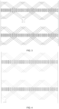
FIG. 2 is a phase diagram of a U-phase short-range winding, a V-phase short-range winding, and a W-phase short-range winding in the iron core slot according to the present application. -
FIG. 3 is a connection diagram of a first branch of the U-phase winding according to the present application. -
FIG. 4 is a connection diagram of a second branch of the U-phase winding according to the present application. -
FIG. 5 is a connection diagram of a third branch of the U-phase winding according to the present application. -
FIG. 6 is a connection diagram of the U-phase winding according to the present application. -
FIG. 7 is a connection diagram of ends of a three-phase winding with the Y-connection manner according to the present application. -
FIG. 8 is a connection diagram of a U-phase winding, a V-phase winding, and a W-phase winding according to the present application. -
FIG. 9 is a connection diagram of ends of the three-phase winding with the delta-connection according to the present application. -
FIG. 10 is a schematic structural diagram of the welding end of three-phase winding according to the present application. -
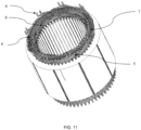
FIG. 11 is a schematic structural diagram of the lead wire end of the three-phase winding according to the present application. - The names of the components represented by the reference numbers are as follows:
1, welding end of the winding end; 2, straight portion of the wire in the iron core and the iron core slot; 3, power lead end; 4, I-pin wire and star point lead wire of the power lead wire (when adopting the Y-connection manner) at the first layer in the iron core slot; 5, U-pin wire at the first layer in the iron core slot; 6, U-pin wire at the second and third layers in the iron core slot; 7, U-pin wire at the fourth and fifth layers in the iron core slot; 8, U-pin wire at the sixth layer in the iron core slot. - The present application will be further described below through specific embodiments.
- A three-branch balanced winding of a six-pole, fifty-four-slot flat copper wire motor with a short range of Y=8, adopts the Y-connection manner, and a number a of parallel branches is 3. The winding connection structure is as shown in
FIG. 1 to FIG. 8 , and the specific structure is as follows. - The winding expansion diagram shows a six-layer flat copper wire winding, that is, there are 6 flat copper wires in each slot number. The number of flat wire layers from the bottom of the slot to the opening of the slot is 1, 2, 3, 4, 5, and 6, which is as shown in
FIG. 1 . - As for the straight portion of the winding, the straight portion of the three-phase flat copper wire winding is evenly divided into three-phase symmetrical windings based on the the short range Y=8, namely the U phase, the V phase and the W phase, as shown in
FIG. 2 . - The winding adopts the Y-connection manner, the number a of parallel branches is 3, and each phase winding is composed of three branches connected in parallel, as shown in
FIG. 7 . - As shown in
FIG. 7 , the U-phase winding is composed of a branch 1 (U1-X1), a branch 2 (U2-X2) and a branch 3 (U3-X3), and the V-phase winding is composed of a branch 1 (V1-Y1), a branch 2 (V2-Y2) and a branch 3 (V3-Y3), the W-phase winding is composed of a branch 1 (W1-Z1), a branch 2 (W2-Z2) and a branch 3 (W3-Z3). - The branch 1 of the U-phase winding, namely a first end U1 of U1-X1, enters from the first layer L1 of a slot 1 of the winding along a current flow direction, finally flows out from a first layer L1 of a slot 12, and the winding connection sequence is: L1 of a slot 1→ L2 of a slot 9→ L3 of a slot 19→ L4 of a slot 27→ L5 of a slot 37→ L6 of a slot 45→ L6 of a slot 54→ L5 of a slot 46→ L4 of a slot 36→ L3 of a slot 28→ L2 of a slot 18→ L1 of a slot 10→ L1 of a slot 2→ L2 of a slot 10→ L3 of a slot 20→ L4 of a slot 28→ L5 of a slot 38→ L6 of a slot 46→ L6 of a slot 1→ L5 of a slot 47→ L4 of a slot 37→ L3 of a slot 29→ L2 of a slot 19→ L1 of a slot 11→ L1 of a slot 3→ L2 of a slot 11→ L3 of a slot 21→ L4 of a slot 29→ L5 of a slot 39→ L6 of a slot 47→ L6 of a slot 2→ L5 of a slot 48→ L4 of a slot 38→ L3 of a slot 30→ L2 of a slot 20→ L1 of a slot 12. The specific connection method can be shown in
FIG. 3 orFIG. 8 . - The branch 2 of the U-phase winding, namely a first end U2 of U2-X2, enters from the first layer L1 of a slot 19 of the winding along a current flow direction, finally flows out from a first layer L1 of a slot 30, and the winding connection sequence is: L1 of a slot 19→ L2 of a slot 27→ L3 of a slot 37→ L4 of a slot 45→ L5 of a slot 1→ L6 of a slot 9→ L6 of a slot 18→ L5 of a slot 10→ L4 of a slot 54→ L3 of a slot 46→ L2 of a slot 36→ L1 of a slot 28→ L1 of a slot 20→ L2 of a slot 28→ L3 of a slot 38→ L4 of a slot 46→ L5 of a slot 2→ L6 of a slot 10→ L6 of a slot 19→ L5 of a slot 11→ L4 of a slot 1→ L3 of a slot 47→ L2 of a slot 37→ L1 of a slot 29→ L1 of a slot 21→ L2 of a slot 29→ L3 of a slot 39→ L4 of a slot 47→ L5 of a slot 3→ L6 of a slot 11→ L6 of a slot 20→ L5 of a slot 12→ L4 of a slot 2→ L3 of a slot 48→ L2 of a slot 38→ L1 of a slot 30. The specific connection method can be shown in
FIG. 4 orFIG. 8 . - The branch 3 of the U-phase winding, namely a first end U1 of U3-X3, enters from the first layer L1 of a slot 37 of the winding along a current flow direction, finally flows out from a first layer L1 of a slot 48, and the winding connection sequence is: L1 of a slot 37→ L2 of a slot 45→ L3 of a slot 1→ L4 of a slot 9→ L5 of a slot 19→ L6 of a slot 27→ L6 of a slot 36→ L5 of a slot 28→ L4 of a slot 18→ L3 of a slot 10→ L2 of a slot 54→ L1 of a slot 46→ L1 of a slot 38→ L2 of a slot 46→ L3 of a slot 2→ L4 of a slot 10→ L5 of a slot 20→ L6 of a slot 28→ L6 of a slot 37→ L5 of a slot 29→ L4 of a slot 19→ L3 of a slot 11→ L2 of a slot 1→ L1 of a slot 47→ L1 of a slot 39→ L2 of a slot 47→ L3 of a slot 3→ L4 of a slot 11→ L5 of a slot 21→ L6 of a slot 29→ L6 of a slot 38→ L5 of a slot 30→ L4 of a slot 20→ L3 of a slot 12→ L2 of a slot 2→ L1 of a slot 48. The specific connection method can be shown in
FIG. 5 orFIG. 8 . - In the same way, the V-phase winding and U-phase winding branches are connected in the same way, except that the starting slot is different, that is, a branch 1 (V1-Y1) of the V-phase winding enters from the first layer L1 of a
slot 7 of the winding along a current flow direction and finally flows out from a first layer L1 of aslot 18, a branch 2 (V2-Y2) of the V-phase winding enters from the first layer L1 of aslot 25 of the winding along a current flow direction and finally flows out from a first layer L1 of aslot 36, a branch 3 (V3-Y3) of the V-phase winding enters from the first layer L1 of aslot 43 of the winding along a current flow direction and finally flows out from a first layer L1 of aslot 54. The detailed connection sequence of the three branches is as shown inFIG. 8 . - The branch 1 of the V-phase winding, namely a first end V1 of V1-Y1, enters from the first layer L1 of a slot 7 of the winding along a current flow direction, finally flows out from a first layer L1 of a slot 18, and the winding connection sequence is: L1 of a slot 7→ L2 of a slot 15→ L3 of a slot 25→ L4 of a slot 33→ L5 of a slot 43→ L6 of a slot 51→ L6 of a slot 6→ L5 of a slot 52→ L4 of a slot 42→ L3 of a slot 34→ L2 of a slot 24→ L1 of a slot 16→ L1 of a slot 8→ L2 of a slot 16→ L3 of a slot 26→ L4 of a slot 34→ L5 of a slot 44→ L6 of a slot 52→ L6 of a slot 7→ L5 of a slot 53→ L4 of a slot 43→ L3 of a slot 35→ L2 of a slot 25→ L1 of a slot 17→ L1 of a slot 9→ L2 of a slot 17→ L3 of a slot 27→ L4 of a slot 35→ L5 of a slot 45→ L6 of a slot 53→ L6 of a slot 8→ L5 of a slot 54→ L4 of a slot 44→ L3 of a slot 36→ L2 of a slot 26→ L1 of a slot 18. The specific connection method can be shown in
FIG. 8 . - The branch 2 of the V-phase winding, namely a first end V2 of V2-Y2, enters from the first layer L1 of a slot 25 of the winding along a current flow direction, finally flows out from a first layer L1 of a slot 36, and the winding connection sequence is: L1 of a slot 25→ L2 of a slot 33→ L3 of a slot 43→ L4 of a slot 51→ L5 of a slot 7→ L6 of a slot 15→ L6 of a slot 24→ L5 of a slot 16→ L4 of a slot 6→ L3 of a slot 52→ L2 of a slot 42→ L1 of a slot 34→ L1 of a slot 26→ L2 of a slot 34→ L3 of a slot 44→ L4 of a slot 52→ L5 of a slot 8→ L6 of a slot 16→ L6 of a slot 25→ L5 of a slot 17→ L4 of a slot 7→ L3 of a slot 53→ L2 of a slot 43→ L1 of a slot 35→ L1 of a slot 27→ L2 of a slot 35→ L3 of a slot 45→ L4 of a slot 53→ L5 of a slot 9→ L6 of a slot 17→ L6 of a slot 26→ L5 of a slot 18→ L4 of a slot 8→ L3 of a slot 54→ L2 of a slot 44→ L1 of a slot 36. The specific connection method can be shown in
FIG. 8 . - The branch 3 of the V-phase winding, namely a first end V3 of V3-Y3, enters from the first layer L1 of a slot 43 of the winding along a current flow direction, finally flows out from a first layer L1 of a slot 54, and the winding connection sequence is: L1 of a slot 43→ L2 of a slot 51→ L3 of a slot 7→ L4 of a slot 15→ L5 of a slot 25→ L6 of a slot 33→ L6 of a slot 42→ L5 of a slot 34→ L4 of a slot 24→ L3 of a slot 16→ L2 of a slot 6→ L1 of a slot 52→ L1 of a slot 44→ L2 of a slot 52→ L3 of a slot 8→ L4 of a slot 16→ L5 of a slot 26→ L6 of a slot 34→ L6 of a slot 43→ L5 of a slot 35→ L4 of a slot 25→ L3 of a slot 17→ L2 of a slot 7→ L1 of a slot 53→ L1 of a slot 45→ L2 of a slot 53→ L3 of a slot 9→ L4 of a slot 17→ L5 of a slot 27→ L6 of a slot 35→ L6 of a slot 44→ L5 of a slot 36→ L4 of a slot 26→ L3 of a slot 18→ L2 of a slot 8→ L1 of a slot 54. The specific connection method can be shown in
FIG. 8 . - In the same way, the W-phase winding and U-phase winding branches are connected in the same way, except that the starting slot is different, that is, a branch 1 (W1-Z1) enters from the first layer L1 of a
slot 13 of the winding along a current flow direction and finally flows out from a first layer L1 of aslot 24, abranch 2 of the W-phase winding (W2-Z2) enters from the first layer L1 of aslot 31 of the winding along a current flow direction and finally flows out from a first layer L1 of aslot 42, abranch 3 of the W-phase winding (W3-Z3) enters from the first layer L1 of aslot 49 of the winding along a current flow direction and finally flows out from a first layer L1 of aslot 6. The detailed connection sequence of the three branches is as shown inFIG. 8 . - The branch 1 of the W-phase winding, namely a first end W1 of W1-Z1, enters from the first layer L1 of a slot 13 of the winding along a current flow direction, finally flows out from a first layer L1 of a slot 24, and the winding connection sequence is: L1 of a slot 13→ L2 of a slot 21→ L3 of a slot 31→ L4 of a slot 39→ L5 of a slot 49→ L6 of a slot 3→ L6 of a slot 12→ L5 of a slot 4→ L4 of a slot 48→ L3 of a slot 40→ L2 of a slot 30→ L1 of a slot 22→ L1 of a slot 14→ L2 of a slot 22→ L3 of a slot 32→ L4 of a slot 40→ L5 of a slot 50→ L6 of a slot 4→ L6 of a slot 13→ L5 of a slot 5→ L4 of a slot 49→ L3 of a slot 41→ L2 of a slot 31→ L1 of a slot 23→ L1 of a slot 15→ L2 of a slot 23→ L3 of a slot 33→ L4 of a slot 41→ L5 of a slot 51→ L6 of a slot 5→ L6 of a slot 14→ L5 of a slot 6→ L4 of a slot 50→ L3 of a slot 42→ L2 of a slot 32→ L1 of a slot 24. The specific connection method can be shown in
FIG. 8 . - The branch 2 of the W-phase winding, namely a first end W1 of W2-Z2, enters from the first layer L1 of a slot 31 of the winding along a current flow direction, finally flows out from a first layer L1 of a slot 42, and the winding connection sequence is: L1 of a slot 31→ L2 of a slot 39→ L3 of a slot 49→ L4 of a slot 3→ L5 of a slot 13→ L6 of a slot 21→ L6 of a slot 30→ L5 of a slot 22→ L4 of a slot 12→ L3 of a slot 4→ L2 of a slot 48→ L1 of a slot 40→ L1 of a slot 32→ L2 of a slot 40→ L3 of a slot 50→ L4 of a slot 4→ L5 of a slot 14→ L6 of a slot 22→ L6 of a slot 31→ L5 of a slot 23→ L4 of a slot 13→ L3 of a slot 5→ L2 of a slot 49→ L1 of a slot 41→ L1 of a slot 33→ L2 of a slot 41→ L3 of a slot 51→ L4 of a slot 5→ L5 of a slot 15→ L6 of a slot 23→ L6 of a slot 32→ L5 of a slot 24→ L4 of a slot 14→ L3 of a slot 6→ L2 of a slot 50→ L1 of a slot 42. The specific connection method can be shown in
FIG. 8 . - The branch 3 of the W-phase winding, namely a first end W3 of W3-Z3, enters from the first layer L1 of a slot 49 of the winding along a current flow direction, finally flows out from a first layer L1 of a slot 6, and the winding connection sequence is: L1 of a slot 49→ L2 of a slot 3→ L3 of a slot 13→ L4 of a slot 21→ L5 of a slot 31→ L6 of a slot 39→ L6 of a slot 48→ L5 of a slot 40→ L4 of a slot 30→ L3 of a slot 22→ L2 of a slot 12→ L1 of a slot 4→ L1 of a slot 50→ L2 of a slot 4→ L3 of a slot 14→ L4 of a slot 22→ L5 of a slot 32→ L6 of a slot 40→ L6 of a slot 49→ L5 of a slot 41→ L4 of a slot 31→ L3 of a slot 23→ L2 of a slot 13→ L1 of a slot 5→ L1 of a slot 51→ L2 of a slot 5→ L3 of a slot 15→ L4 of a slot 23→ L5 of a slot 33→ L6 of a slot 41→ L6 of a slot 50→ L5 of a slot 42→ L4 of a slot 32→ L3 of a slot 24→ L2 of a slot 14→ L1 of a slot 6. The specific connection method can be shown in
FIG. 8 . - As shown in
FIG. 7 andFIG. 8 , the U phase (composed of U1, U2, U3), the V phase (composed of V1, V2, V3), and the W phase (composed of W1, W2, W3) of the power lead wire are distributed at the first layer of the winding. When the connection at the end of the three-phase power lead wire is arranged in this way, it can be arranged in the end axial space or the end radial space, which is conducive to flexible switching according to the installation space, especially the end axial height can be significantly reduced by utilizing the end radial space. The three star points X1-Y1-Z1, X2-Y2-Z2, and X3-Y3-Z3 are also distributed at the first layer of the winding. In this way, the arrangement can be flexibly switched between the end axial space and the end radial space according to the installation space. - A three-branch balanced winding of a six-pole, fifty-four-slot flat copper wire motor with a short range of Y=8, adopts the delta-connection method, and a number a of parallel branches is 3. The straight portion of the winding in the winding connection structure, the welding end, and the power lead wire end are exactly the same as those in the first embodiment, except that the connection method of the three-phase power wire is different and there is no star point connection. The specific connection method is as shown in
FIG. 9 . - The U phase of the power lead wire is composed of U1, U2, U3, Y1, Y2, Y3, the V phase is composed of V1, V2, V3, Z1, Z2, Z3, and the W phase is composed of W1, W2, W3, X1, X2, X3.
Claims (9)
- A three-branch balanced winding of a six-pole, fifty-four-slot flat copper wire motor, characterized by comprising:a three-phase flat copper wire winding distributed symmetrically along a circumferential direction of an iron core slot, wherein the three-phase flat copper wire winding comprises a wire straight portion (2) distributed in the iron core slot, a welding end (1) distributed at one side of an end of an iron core (2), and a power lead wire end (3) distributed at another side of the iron core (2); andspans of the welding end (1) are equal, and heights of the lead welding ends (1) are equal; the power lead wire end (3) is composed of four U-Pin wire types and one I-pin wire type, and a first layer of the power lead wire end (3) is composed of an I-Pin wire (4) and an U-pin wire (5) with an equal span; both a second layer and a third layer are composed of U-pin wires (6) with an equal span; both a fourth layer and a fifth layer are composed of U-pin wires (7) with an equal span; a sixth layer is composed of a U-pin wire (8) with an equal span; the I-Pin wire (4) comprises a U-phase power wire, a V-phase power wire, a W-phase power wire, and a star point wire when a Y-connection manner is adopted in the winding, and the U-phase power wire, the V-phase power wire, the W-phase power wire, and the star point wire are distributed at an end of the winding at the first layer of the iron core slot; no other protruding special-shaped wires and bridge wires are provided.
- The three-branch balanced winding of the six-pole, fifty-four-slot flat copper wire motor according to claim 1, wherein:
the three-phase flat copper wire winding is a six-layer winding, and each phase winding is composed of three branches connected in parallel; a connection sequence of each parallel branch is configured as follows: entering from a first layer L1 of the iron core slot; passing through a second layer L2, a third layer L3, a fourth layer L4, a fifth layer L5, and a sixth layer L6 along a forward direction in sequence; passing through the sixth layer L6, the fifth layer L5, the fourth layer L4, the third layer L3, the second layer L2, the first layer L1 along a reverse direction in sequence; passing through the first layer L1, the second layer L2, the third layer L3, the fourth layer L4, the fifth layer L5, and the sixth layer L6 along the forward direction; passing through the sixth layer L6, the fifth layer L5, the fourth layer L4, the third layer L3, the second layer L2, the first layer L1 along the reverse direction; passing through the first layer L1, the second layer L2, the third layer L3, the fourth layer L4, the fifth layer L5, and the sixth layer L6 along the forward direction; then passing through the sixth layer L6, the fifth layer L5, the fourth layer L4, the third layer L3, and the second layer L2 along the reverse direction; finally leading out from the first layer L1. - The three-branch balanced winding of the six-pole, fifty-four-slot flat copper wire motor according to claim 1 or 2, wherein:the U-phase power wire, the V-phase power wire and the W-phase of the three-phase flat copper wire winding is configured to adopt a Y-connection manner or a delta connection manner; andthe three-phase flat copper wire winding is configured to adopt a short span with a span Y of eight, a full span with a span Y of nine, or a long span with a span Y of ten.
- The three-branch balanced winding of the six-pole fifty-four-slot flat copper wire motor according to claim 1 or 2, wherein the U-phase power wire, the V-phase power wire, the W-phase power wire, the star point wire are evenly distributed at the end of the winding at the first layer of the iron core slot when the winding is configured to adopt a Y-connection manner.
- The three-branch balanced winding of the six-pole, fifty-four-slot flat copper wire motor according to claim 3, wherein the U-phase power wire, the V-phase power wire, the W-phase power wire, the star point wire are evenly distributed at the end of the winding at the first layer of the iron core slot when the winding is configured to adopt a Y-connection manner.
- A method of using the three-branch balanced winding of the six-pole fifty-four-slot flat copper wire motor according to claim 1 or 2, wherein the method is implemented in sequence as follows:a branch 1 of the U-phase winding, namely a first end U1 of U1-X1, enters from the first layer L1 of a slot 1 of the winding along a current flow direction, finally flows out from a first layer L1 of a slot 12, and the winding connection sequence is: L1 of a slot 1→ L2 of a slot 9→ L3 of a slot 19→ L4 of a slot 27→ L5 of a slot 37→ L6 of a slot 45→ L6 of a slot 54→ L5 of a slot 46→ L4 of a slot 36→ L3 of a slot 28→ L2 of a slot 18→ L1 of a slot 10→ L1 of a slot 2→ L2 of a slot 10→ L3 of a slot 20→ L4 of a slot 28→ L5 of a slot 38→ L6 of a slot 46→ L6 of a slot 1→ L5 of a slot 47→ L4 of a slot 37→ L3 of a slot 29→ L2 of a slot 19→ L1 of a slot 11→ L1 of a slot 3→ L2 of a slot 11→ L3 of a slot 21→ L4 of a slot 29→ L5 of a slot 39→ L6 of a slot 47→ L6 of a slot 2→ L5 of a slot 48→ L4 of a slot 38→ L3 of a slot 30→ L2 of a slot 20→ L1 of a slot 12;a branch 2 of the U-phase winding, namely a first end U2 of U2-X2, enters from the first layer L1 of a slot 19 of the winding along a current flow direction, finally flows out from a first layer L1 of a slot 30, and the winding connection sequence is: L1 of a slot 19→ L2 of a slot 27→ L3 of a slot 37→ L4 of a slot 45→ L5 of a slot 1→ L6 of a slot 9→ L6 of a slot 18→ L5 of a slot 10→ L4 of a slot 54→ L3 of a slot 46→ L2 of a slot 36→ L1 of a slot 28→ L1 of a slot 20→ L2 of a slot 28→ L3 of a slot 38→ L4 of a slot 46→ L5 of a slot 2→ L6 of a slot 10→ L6 of a slot 19→ L5 of a slot 11→ L4 of a slot 1→ L3 of a slot 47→ L2 of a slot 37→ L1 of a slot 29→ L1 of a slot 21→ L2 of a slot 29→ L3 of a slot 39→ L4 of a slot 47→ L5 of a slot 3→ L6 of a slot 11→ L6 of a slot 20→ L5 of a slot 12→ L4 of a slot 2→ L3 of a slot 48→ L2 of a slot 38→ L1 of a slot 30;a branch 3 of the U-phase winding, namely a first end U1 of U3-X3, enters from the first layer L1 of a slot 37 of the winding along a current flow direction, finally flows out from a first layer L1 of a slot 48, and the winding connection sequence is: L1 of a slot 37→ L2 of a slot 45→ L3 of a slot 1→ L4 of a slot 9→ L5 of a slot 19→ L6 of a slot 27→ L6 of a slot 36→ L5 of a slot 28→ L4 of a slot 18→ L3 of a slot 10→ L2 of a slot 54→ L1 of a slot 46→ L1 of a slot 38→ L2 of a slot 46→ L3 of a slot 2→ L4 of a slot 10→ L5 of a slot 20→ L6 of a slot 28→ L6 of a slot 37→ L5 of a slot 29→ L4 of a slot 19→ L3 of a slot 11→ L2 of a slot 1→ L1 of a slot 47→ L1 of a slot 39→ L2 of a slot 47→ L3 of a slot 3→ L4 of a slot 11→ L5 of a slot 21→ L6 of a slot 29→ L6 of a slot 38→ L5 of a slot 30→ L4 of a slot 20→ L3 of a slot 12→ L2 of a slot 2→ L1 of a slot 48;a branch 1 of the V-phase winding, namely a first end V1 of V1-Y1, enters from the first layer L1 of a slot 7 of the winding along a current flow direction, finally flows out from a first layer L1 of a slot 18, and the winding connection sequence is: L1 of a slot 7→ L2 of a slot 15→ L3 of a slot 25→ L4 of a slot 33→ L5 of a slot 43→ L6 of a slot 51→ L6 of a slot 6→ L5 of a slot 52→ L4 of a slot 42→ L3 of a slot 34→ L2 of a slot 24→ L1 of a slot 16→ L1 of a slot 8→ L2 of a slot 16→ L3 of a slot 26→ L4 of a slot 34→ L5 of a slot 44→ L6 of a slot 52→ L6 of a slot 7→ L5 of a slot 53→ L4 of a slot 43→ L3 of a slot 35→ L2 of a slot 25→ L1 of a slot 17→ L1 of a slot 9→ L2 of a slot 17→ L3 of a slot 27→ L4 of a slot 35→ L5 of a slot 45→ L6 of a slot 53→ L6 of a slot 8→ L5 of a slot 54→ L4 of a slot 44→ L3 of a slot 36→ L2 of a slot 26→ L1 of a slot 18;a branch 2 of the V-phase winding, namely a first end V2 of V2-Y2, enters from the first layer L1 of a slot 25 of the winding along a current flow direction, finally flows out from a first layer L1 of a slot 36, and the winding connection sequence is: L1 of a slot 25→ L2 of a slot 33→ L3 of a slot 43→ L4 of a slot 51→ L5 of a slot 7→ L6 of a slot 15→ L6 of a slot 24→ L5 of a slot 16→ L4 of a slot 6→ L3 of a slot 52→ L2 of a slot 42→ L1 of a slot 34→ L1 of a slot 26→ L2 of a slot 34→ L3 of a slot 44→ L4 of a slot 52→ L5 of a slot 8→ L6 of a slot 16→ L6 of a slot 25→ L5 of a slot 17→ L4 of a slot 7→ L3 of a slot 53→ L2 of a slot 43→ L1 of a slot 35→ L1 of a slot 27→ L2 of a slot 35→ L3 of a slot 45→ L4 of a slot 53→ L5 of a slot 9→ L6 of a slot 17→ L6 of a slot 26→ L5 of a slot 18→ L4 of a slot 8→ L3 of a slot 54→ L2 of a slot 44→ L1 of a slot 36;a branch 3 of the V-phase winding, namely a first end V3 of V3-Y3, enters from the first layer L1 of a slot 43 of the winding along a current flow direction, finally flows out from a first layer L1 of a slot 54, and the winding connection sequence is: L1 of a slot 43→ L2 of a slot 51→ L3 of a slot 7→ L4 of a slot 15→ L5 of a slot 25→ L6 of a slot 33→ L6 of a slot 42→ L5 of a slot 34→ L4 of a slot 24→ L3 of a slot 16→ L2 of a slot 6→ L1 of a slot 52→ L1 of a slot 44→ L2 of a slot 52→ L3 of a slot 8→ L4 of a slot 16→ L5 of a slot 26→ L6 of a slot 34→ L6 of a slot 43→ L5 of a slot 35→ L4 of a slot 25→ L3 of a slot 17→ L2 of a slot 7→ L1 of a slot 53→ L1 of a slot 45→ L2 of a slot 53→ L3 of a slot 9→ L4 of a slot 17→ L5 of a slot 27→ L6 of a slot 35→ L6 of a slot 44→ L5 of a slot 36→ L4 of a slot 26→ L3 of a slot 18→ L2 of a slot 8→ L1 of a slot 54;a branch 1 of the W-phase winding, namely a first end W1 of W1-Z1, enters from the first layer L1 of a slot 13 of the winding along a current flow direction, finally flows out from a first layer L1 of a slot 24, and the winding connection sequence is: L1 of a slot 13→ L2 of a slot 21→ L3 of a slot 31→ L4 of a slot 39→ L5 of a slot 49→ L6 of a slot 3→ L6 of a slot 12→ L5 of a slot 4→ L4 of a slot 48→ L3 of a slot 40→ L2 of a slot 30→ L1 of a slot 22→ L1 of a slot 14→ L2 of a slot 22→ L3 of a slot 32→ L4 of a slot 40→ L5 of a slot 50→ L6 of a slot 4→ L6 of a slot 13→ L5 of a slot 5→ L4 of a slot 49→ L3 of a slot 41→ L2 of a slot 31→ L1 of a slot 23→ L1 of a slot 15→ L2 of a slot 23→ L3 of a slot 33→ L4 of a slot 41→ L5 of a slot 51→ L6 of a slot 5→ L6 of a slot 14→ L5 of a slot 6→ L4 of a slot 50→ L3 of a slot 42→ L2 of a slot 32→ L1 of a slot 24;a branch 2 of the W-phase winding, namely a first end W1 of W2-Z2, enters from the first layer L1 of a slot 31 of the winding along a current flow direction, finally flows out from a first layer L1 of a slot 42, and the winding connection sequence is: L1 of a slot 31→ L2 of a slot 39→ L3 of a slot 49→ L4 of a slot 3→ L5 of a slot 13→ L6 of a slot 21→ L6 of a slot 30→ L5 of a slot 22→ L4 of a slot 12→ L3 of a slot 4→ L2 of a slot 48→ L1 of a slot 40→ L1 of a slot 32→ L2 of a slot 40→ L3 of a slot 50→ L4 of a slot 4→ L5 of a slot 14→ L6 of a slot 22→ L6 of a slot 31→ L5 of a slot 23→ L4 of a slot 13→ L3 of a slot 5→ L2 of a slot 49→ L1 of a slot 41→ L1 of a slot 33→ L2 of a slot 41→ L3 of a slot 51→ L4 of a slot 5→ L5 of a slot 15→ L6 of a slot 23→ L6 of a slot 32→ L5 of a slot 24→ L4 of a slot 14→ L3 of a slot 6→ L2 of a slot 50→ L1 of a slot 42;a branch 3 of the W-phase winding, namely a first end W3 of W3-Z3, enters from the first layer L1 of a slot 49 of the winding along a current flow direction, finally flows out from a first layer L1 of a slot 6, and the winding connection sequence is: L1 of a slot 49→ L2 of a slot 3→ L3 of a slot 13→ L4 of a slot 21→ L5 of a slot 31→ L6 of a slot 39→ L6 of a slot 48→ L5 of a slot 40→ L4 of a slot 30→ L3 of a slot 22→ L2 of a slot 12→ L1 of a slot 4→ L1 of a slot 50→ L2 of a slot 4→ L3 of a slot 14→ L4 of a slot 22→ L5 of a slot 32→ L6 of a slot 40→ L6 of a slot 49→ L5 of a slot 41→ L4 of a slot 31→ L3 of a slot 23→ L2 of a slot 13→ L1 of a slot 5→ L1 of a slot 51→ L2 of a slot 5→ L3 of a slot 15→ L4 of a slot 23→ L5 of a slot 33→ L6 of a slot 41→ L6 of a slot 50→ L5 of a slot 42→ L4 of a slot 32→ L3 of a slot 24→ L2 of a slot 14→ L1 of a slot 6.
- The method of using the three-branch balanced winding of the six-pole fifty-four-slot flat copper wire motor according to claim 3, wherein the method is implemented in sequence as follows:a branch 1 of the U-phase winding, namely a first end U1 of U1-X1, enters from the first layer L1 of a slot 1 of the winding along a current flow direction, finally flows out from a first layer L1 of a slot 12, and the winding connection sequence is: L1 of a slot 1→ L2 of a slot 9→ L3 of a slot 19→ L4 of a slot 27→ L5 of a slot 37→ L6 of a slot 45→ L6 of a slot 54→ L5 of a slot 46→ L4 of a slot 36→ L3 of a slot 28→ L2 of a slot 18→ L1 of a slot 10→ L1 of a slot 2→ L2 of a slot 10→ L3 of a slot 20→ L4 of a slot 28→ L5 of a slot 38→ L6 of a slot 46→ L6 of a slot 1→ L5 of a slot 47→ L4 of a slot 37→ L3 of a slot 29→ L2 of a slot 19→ L1 of a slot 11→ L1 of a slot 3→ L2 of a slot 11→ L3 of a slot 21→ L4 of a slot 29→ L5 of a slot 39→ L6 of a slot 47→ L6 of a slot 2→ L5 of a slot 48→ L4 of a slot 38→ L3 of a slot 30→ L2 of a slot 20→ L1 of a slot 12;a branch 2 of the U-phase winding, namely a first end U2 of U2-X2, enters from the first layer L1 of a slot 19 of the winding along a current flow direction, finally flows out from a first layer L1 of a slot 30, and the winding connection sequence is: L1 of a slot 19→ L2 of a slot 27→ L3 of a slot 37→ L4 of a slot 45→ L5 of a slot 1→ L6 of a slot 9→ L6 of a slot 18→ L5 of a slot 10→ L4 of a slot 54→ L3 of a slot 46→ L2 of a slot 36→ L1 of a slot 28→ L1 of a slot 20→ L2 of a slot 28→ L3 of a slot 38→ L4 of a slot 46→ L5 of a slot 2→ L6 of a slot 10→ L6 of a slot 19→ L5 of a slot 11→ L4 of a slot 1→ L3 of a slot 47→ L2 of a slot 37→ L1 of a slot 29→ L1 of a slot 21→ L2 of a slot 29→ L3 of a slot 39→ L4 of a slot 47→ L5 of a slot 3→ L6 of a slot 11→ L6 of a slot 20→ L5 of a slot 12→ L4 of a slot 2→ L3 of a slot 48→ L2 of a slot 38→ L1 of a slot 30;a branch 3 of the U-phase winding, namely a first end U1 of U3-X3, enters from the first layer L1 of a slot 37 of the winding along a current flow direction, finally flows out from a first layer L1 of a slot 48, and the winding connection sequence is: L1 of a slot 37→ L2 of a slot 45→ L3 of a slot 1→ L4 of a slot 9→ L5 of a slot 19→ L6 of a slot 27→ L6 of a slot 36→ L5 of a slot 28→ L4 of a slot 18→ L3 of a slot 10→ L2 of a slot 54→ L1 of a slot 46→ L1 of a slot 38→ L2 of a slot 46→ L3 of a slot 2→ L4 of a slot 10→ L5 of a slot 20→ L6 of a slot 28→ L6 of a slot 37→ L5 of a slot 29→ L4 of a slot 19→ L3 of a slot 11→ L2 of a slot 1→ L1 of a slot 47→ L1 of a slot 39→ L2 of a slot 47→ L3 of a slot 3→ L4 of a slot 11→ L5 of a slot 21→ L6 of a slot 29→ L6 of a slot 38→ L5 of a slot 30→ L4 of a slot 20→ L3 of a slot 12→ L2 of a slot 2→ L1 of a slot 48;a branch 1 of the V-phase winding, namely a first end V1 of V1-Y1, enters from the first layer L1 of a slot 7 of the winding along a current flow direction, finally flows out from a first layer L1 of a slot 18, and the winding connection sequence is: L1 of a slot 7→ L2 of a slot 15→ L3 of a slot 25→ L4 of a slot 33→ L5 of a slot 43→ L6 of a slot 51→ L6 of a slot 6→ L5 of a slot 52→ L4 of a slot 42→ L3 of a slot 34→ L2 of a slot 24→ L1 of a slot 16→ L1 of a slot 8→ L2 of a slot 16→ L3 of a slot 26→ L4 of a slot 34→ L5 of a slot 44→ L6 of a slot 52→ L6 of a slot 7→ L5 of a slot 53→ L4 of a slot 43→ L3 of a slot 35→ L2 of a slot 25→ L1 of a slot 17→ L1 of a slot 9→ L2 of a slot 17→ L3 of a slot 27→ L4 of a slot 35→ L5 of a slot 45→ L6 of a slot 53→ L6 of a slot 8→ L5 of a slot 54→ L4 of a slot 44→ L3 of a slot 36→ L2 of a slot 26→ L1 of a slot 18;a branch 2 of the V-phase winding, namely a first end V2 of V2-Y2, enters from the first layer L1 of a slot 25 of the winding along a current flow direction, finally flows out from a first layer L1 of a slot 36, and the winding connection sequence is: L1 of a slot 25→ L2 of a slot 33→ L3 of a slot 43→ L4 of a slot 51→ L5 of a slot 7→ L6 of a slot 15→ L6 of a slot 24→ L5 of a slot 16→ L4 of a slot 6→ L3 of a slot 52→ L2 of a slot 42→ L1 of a slot 34→ L1 of a slot 26→ L2 of a slot 34→ L3 of a slot 44→ L4 of a slot 52→ L5 of a slot 8→ L6 of a slot 16→ L6 of a slot 25→ L5 of a slot 17→ L4 of a slot 7→ L3 of a slot 53→ L2 of a slot 43→ L1 of a slot 35→ L1 of a slot 27→ L2 of a slot 35→ L3 of a slot 45→ L4 of a slot 53→ L5 of a slot 9→ L6 of a slot 17→ L6 of a slot 26→ L5 of a slot 18→ L4 of a slot 8→ L3 of a slot 54→ L2 of a slot 44→ L1 of a slot 36;a branch 3 of the V-phase winding, namely a first end V3 of V3-Y3, enters from the first layer L1 of a slot 43 of the winding along a current flow direction, finally flows out from a first layer L1 of a slot 54, and the winding connection sequence is: L1 of a slot 43→ L2 of a slot 51→ L3 of a slot 7→ L4 of a slot 15→ L5 of a slot 25→ L6 of a slot 33→ L6 of a slot 42→ L5 of a slot 34→ L4 of a slot 24→ L3 of a slot 16→ L2 of a slot 6→ L1 of a slot 52→ L1 of a slot 44→ L2 of a slot 52→ L3 of a slot 8→ L4 of a slot 16→ L5 of a slot 26→ L6 of a slot 34→ L6 of a slot 43→ L5 of a slot 35→ L4 of a slot 25→ L3 of a slot 17→ L2 of a slot 7→ L1 of a slot 53→ L1 of a slot 45→ L2 of a slot 53→ L3 of a slot 9→ L4 of a slot 17→ L5 of a slot 27→ L6 of a slot 35→ L6 of a slot 44→ L5 of a slot 36→ L4 of a slot 26→ L3 of a slot 18→ L2 of a slot 8→ L1 of a slot 54;a branch 1 of the W-phase winding, namely a first end W1 of W1-Z1, enters from the first layer L1 of a slot 13 of the winding along a current flow direction, finally flows out from a first layer L1 of a slot 24, and the winding connection sequence is: L1 of a slot 13→ L2 of a slot 21→ L3 of a slot 31→ L4 of a slot 39→ L5 of a slot 49→ L6 of a slot 3→ L6 of a slot 12→ L5 of a slot 4→ L4 of a slot 48→ L3 of a slot 40→ L2 of a slot 30→ L1 of a slot 22→ L1 of a slot 14→ L2 of a slot 22→ L3 of a slot 32→ L4 of a slot 40→ L5 of a slot 50→ L6 of a slot 4→ L6 of a slot 13→ L5 of a slot 5→ L4 of a slot 49→ L3 of a slot 41→ L2 of a slot 31→ L1 of a slot 23→ L1 of a slot 15→ L2 of a slot 23→ L3 of a slot 33→ L4 of a slot 41→ L5 of a slot 51→ L6 of a slot 5→ L6 of a slot 14→ L5 of a slot 6→ L4 of a slot 50→ L3 of a slot 42→ L2 of a slot 32→ L1 of a slot 24;a branch 2 of the W-phase winding, namely a first end W2 of W2-Z2, enters from the first layer L1 of a slot 31 of the winding along a current flow direction, finally flows out from a first layer L1 of a slot 42, and the winding connection sequence is: L1 of a slot 31→ L2 of a slot 39→ L3 of a slot 49→ L4 of a slot 3→ L5 of a slot 13→ L6 of a slot 21→ L6 of a slot 30→ L5 of a slot 22→ L4 of a slot 12→ L3 of a slot 4→ L2 of a slot 48→ L1 of a slot 40→ L1 of a slot 32→ L2 of a slot 40→ L3 of a slot 50→ L4 of a slot 4→ L5 of a slot 14→ L6 of a slot 22→ L6 of a slot 31→ L5 of a slot 23→ L4 of a slot 13→ L3 of a slot 5→ L2 of a slot 49→ L1 of a slot 41→ L1 of a slot 33→ L2 of a slot 41→ L3 of a slot 51→ L4 of a slot 5→ L5 of a slot 15→ L6 of a slot 23→ L6 of a slot 32→ L5 of a slot 24→ L4 of a slot 14→ L3 of a slot 6→ L2 of a slot 50→ L1 of a slot 42;a branch 3 of the W-phase winding, namely a first end W3 of W3-Z3, enters from the first layer L1 of a slot 49 of the winding along a current flow direction, finally flows out from a first layer L1 of a slot 6, and the winding connection sequence is: L1 of a slot 49→ L2 of a slot 3→ L3 of a slot 13→ L4 of a slot 21→ L5 of a slot 31→ L6 of a slot 39→ L6 of a slot 48→ L5 of a slot 40→ L4 of a slot 30→ L3 of a slot 22→ L2 of a slot 12→ L1 of a slot 4→ L1 of a slot 50→ L2 of a slot 4→ L3 of a slot 14→ L4 of a slot 22→ L5 of a slot 32→ L6 of a slot 40→ L6 of a slot 49→ L5 of a slot 41→ L4 of a slot 31→ L3 of a slot 23→ L2 of a slot 13→ L1 of a slot 5→ L1 of a slot 51→ L2 of a slot 5→ L3 of a slot 15→ L4 of a slot 23→ L5 of a slot 33→ L6 of a slot 41→ L6 of a slot 50→ L5 of a slot 42→ L4 of a slot 32→ L3 of a slot 24→ L2 of a slot 14→ L1 of a slot 6.
- The method of using the three-branch balanced winding of the six-pole fifty-four-slot flat copper wire motor according to claim 4, wherein the method is implemented in sequence as follows:a branch 1 of the U-phase winding, namely a first end U1 of U1-X1, enters from the first layer L1 of a slot 1 of the winding along a current flow direction, finally flows out from a first layer L1 of a slot 12, and the winding connection sequence is: L1 of a slot 1→ L2 of a slot 9→ L3 of a slot 19→ L4 of a slot 27→ L5 of a slot 37→ L6 of a slot 45→ L6 of a slot 54→ L5 of a slot 46→ L4 of a slot 36→ L3 of a slot 28→ L2 of a slot 18→ L1 of a slot 10→ L1 of a slot 2→ L2 of a slot 10→ L3 of a slot 20→ L4 of a slot 28→ L5 of a slot 38→ L6 of a slot 46→ L6 of a slot 1→ L5 of a slot 47→ L4 of a slot 37→ L3 of a slot 29→ L2 of a slot 19→ L1 of a slot 11→ L1 of a slot 3→ L2 of a slot 11→ L3 of a slot 21→ L4 of a slot 29→ L5 of a slot 39→ L6 of a slot 47→ L6 of a slot 2→ L5 of a slot 48→ L4 of a slot 38→ L3 of a slot 30→ L2 of a slot 20→ L1 of a slot 12;a branch 2 of the U-phase winding, namely a first end U2 of U2-X2, enters from the first layer L1 of a slot 19 of the winding along a current flow direction, finally flows out from a first layer L1 of a slot 30, and the winding connection sequence is: L1 of a slot 19→ L2 of a slot 27→ L3 of a slot 37→ L4 of a slot 45→ L5 of a slot 1→ L6 of a slot 9→ L6 of a slot 18→ L5 of a slot 10→ L4 of a slot 54→ L3 of a slot 46→ L2 of a slot 36→ L1 of a slot 28→ L1 of a slot 20→ L2 of a slot 28→ L3 of a slot 38→ L4 of a slot 46→ L5 of a slot 2→ L6 of a slot 10→ L6 of a slot 19→ L5 of a slot 11→ L4 of a slot 1→ L3 of a slot 47→ L2 of a slot 37→ L1 of a slot 29→ L1 of a slot 21→ L2 of a slot 29→ L3 of a slot 39→ L4 of a slot 47→ L5 of a slot 3→ L6 of a slot 11→ L6 of a slot 20→ L5 of a slot 12→ L4 of a slot 2→ L3 of a slot 48→ L2 of a slot 38→ L1 of a slot 30;a branch 3 of the U-phase winding, namely a first end U1 of U3-X3, enters from the first layer L1 of a slot 37 of the winding along a current flow direction, finally flows out from a first layer L1 of a slot 48, and the winding connection sequence is: L1 of a slot 37→ L2 of a slot 45→ L3 of a slot 1→ L4 of a slot 9→ L5 of a slot 19→ L6 of a slot 27→ L6 of a slot 36→ L5 of a slot 28→ L4 of a slot 18→ L3 of a slot 10→ L2 of a slot 54→ L1 of a slot 46→ L1 of a slot 38→ L2 of a slot 46→ L3 of a slot 2→ L4 of a slot 10→ L5 of a slot 20→ L6 of a slot 28→ L6 of a slot 37→ L5 of a slot 29→ L4 of a slot 19→ L3 of a slot 11→ L2 of a slot 1→ L1 of a slot 47→ L1 of a slot 39→ L2 of a slot 47→ L3 of a slot 3→ L4 of a slot 11→ L5 of a slot 21→ L6 of a slot 29→ L6 of a slot 38→ L5 of a slot 30→ L4 of a slot 20→ L3 of a slot 12→ L2 of a slot 2→ L1 of a slot 48;a branch 1 of the V-phase winding, namely a first end V1 of V1-Y1, enters from the first layer L1 of a slot 7 of the winding along a current flow direction, finally flows out from a first layer L1 of a slot 18, and the winding connection sequence is: L1 of a slot 7→ L2 of a slot 15→ L3 of a slot 25→ L4 of a slot 33→ L5 of a slot 43→ L6 of a slot 51→ L6 of a slot 6→ L5 of a slot 52→ L4 of a slot 42→ L3 of a slot 34→ L2 of a slot 24→ L1 of a slot 16→ L1 of a slot 8→ L2 of a slot 16→ L3 of a slot 26→ L4 of a slot 34→ L5 of a slot 44→ L6 of a slot 52→ L6 of a slot 7→ L5 of a slot 53→ L4 of a slot 43→ L3 of a slot 35→ L2 of a slot 25→ L1 of a slot 17→ L1 of a slot 9→ L2 of a slot 17→ L3 of a slot 27→ L4 of a slot 35→ L5 of a slot 45→ L6 of a slot 53→ L6 of a slot 8→ L5 of a slot 54→ L4 of a slot 44→ L3 of a slot 36→ L2 of a slot 26→ L1 of a slot 18;a branch 2 of the V-phase winding, namely a first end V2 of V2-Y2, enters from the first layer L1 of a slot 25 of the winding along a current flow direction, finally flows out from a first layer L1 of a slot 36, and the winding connection sequence is: L1 of a slot 25→ L2 of a slot 33→ L3 of a slot 43→ L4 of a slot 51→ L5 of a slot 7→ L6 of a slot 15→ L6 of a slot 24→ L5 of a slot 16→ L4 of a slot 6→ L3 of a slot 52→ L2 of a slot 42→ L1 of a slot 34→ L1 of a slot 26→ L2 of a slot 34→ L3 of a slot 44→ L4 of a slot 52→ L5 of a slot 8→ L6 of a slot 16→ L6 of a slot 25→ L5 of a slot 17→ L4 of a slot 7→ L3 of a slot 53→ L2 of a slot 43→ L1 of a slot 35→ L1 of a slot 27→ L2 of a slot 35→ L3 of a slot 45→ L4 of a slot 53→ L5 of a slot 9→ L6 of a slot 17→ L6 of a slot 26→ L5 of a slot 18→ L4 of a slot 8→ L3 of a slot 54→ L2 of a slot 44→ L1 of a slot 36;a branch 3 of the V-phase winding, namely a first end V3 of V3-Y3, enters from the first layer L1 of a slot 43 of the winding along a current flow direction, finally flows out from a first layer L1 of a slot 54, and the winding connection sequence is: L1 of a slot 43→ L2 of a slot 51→ L3 of a slot 7→ L4 of a slot 15→ L5 of a slot 25→ L6 of a slot 33→ L6 of a slot 42→ L5 of a slot 34→ L4 of a slot 24→ L3 of a slot 16→ L2 of a slot 6→ L1 of a slot 52→ L1 of a slot 44→ L2 of a slot 52→ L3 of a slot 8→ L4 of a slot 16→ L5 of a slot 26→ L6 of a slot 34→ L6 of a slot 43→ L5 of a slot 35→ L4 of a slot 25→ L3 of a slot 17→ L2 of a slot 7→ L1 of a slot 53→ L1 of a slot 45→ L2 of a slot 53→ L3 of a slot 9→ L4 of a slot 17→ L5 of a slot 27→ L6 of a slot 35→ L6 of a slot 44→ L5 of a slot 36→ L4 of a slot 26→ L3 of a slot 18→ L2 of a slot 8→ L1 of a slot 54;a branch 1 of the W-phase winding, namely a first end W1 of W1-Z1, enters from the first layer L1 of a slot 13 of the winding along a current flow direction, finally flows out from a first layer L1 of a slot 24, and the winding connection sequence is: L1 of a slot 13→ L2 of a slot 21→ L3 of a slot 31→ L4 of a slot 39→ L5 of a slot 49→ L6 of a slot 3→ L6 of a slot 12→ L5 of a slot 4→ L4 of a slot 48→ L3 of a slot 40→ L2 of a slot 30→ L1 of a slot 22→ L1 of a slot 14→ L2 of a slot 22→ L3 of a slot 32→ L4 of a slot 40→ L5 of a slot 50→ L6 of a slot 4→ L6 of a slot 13→ L5 of a slot 5→ L4 of a slot 49→ L3 of a slot 41→ L2 of a slot 31→ L1 of a slot 23→ L1 of a slot 15→ L2 of a slot 23→ L3 of a slot 33→ L4 of a slot 41→ L5 of a slot 51→ L6 of a slot 5→ L6 of a slot 14→ L5 of a slot 6→ L4 of a slot 50→ L3 of a slot 42→ L2 of a slot 32→ L1 of a slot 24;a branch 2 of the W-phase winding, namely a first end W2 of W2-Z2, enters from the first layer L1 of a slot 31 of the winding along a current flow direction, finally flows out from a first layer L1 of a slot 42, and the winding connection sequence is: L1 of a slot 31→ L2 of a slot 39→ L3 of a slot 49→ L4 of a slot 3→ L5 of a slot 13→ L6 of a slot 21→ L6 of a slot 30→ L5 of a slot 22→ L4 of a slot 12→ L3 of a slot 4→ L2 of a slot 48→ L1 of a slot 40→ L1 of a slot 32→ L2 of a slot 40→ L3 of a slot 50→ L4 of a slot 4→ L5 of a slot 14→ L6 of a slot 22→ L6 of a slot 31→ L5 of a slot 23→ L4 of a slot 13→ L3 of a slot 5→ L2 of a slot 49→ L1 of a slot 41→ L1 of a slot 33→ L2 of a slot 41→ L3 of a slot 51→ L4 of a slot 5→ L5 of a slot 15→ L6 of a slot 23→ L6 of a slot 32→ L5 of a slot 24→ L4 of a slot 14→ L3 of a slot 6→ L2 of a slot 50→ L1 of a slot 42;a branch 3 of the W-phase winding, namely a first end W3 of W3-Z3, enters from the first layer L1 of a slot 49 of the winding along a current flow direction, finally flows out from a first layer L1 of a slot 6, and the winding connection sequence is: L1 of a slot 49→ L2 of a slot 3→ L3 of a slot 13→ L4 of a slot 21→ L5 of a slot 31→ L6 of a slot 39→ L6 of a slot 48→ L5 of a slot 40→ L4 of a slot 30→ L3 of a slot 22→ L2 of a slot 12→ L1 of a slot 4→ L1 of a slot 50→ L2 of a slot 4→ L3 of a slot 14→ L4 of a slot 22→ L5 of a slot 32→ L6 of a slot 40→ L6 of a slot 49→ L5 of a slot 41→ L4 of a slot 31→ L3 of a slot 23→ L2 of a slot 13→ L1 of a slot 5→ L1 of a slot 51→ L2 of a slot 5→ L3 of a slot 15→ L4 of a slot 23→ L5 of a slot 33→ L6 of a slot 41→ L6 of a slot 50→ L5 of a slot 42→ L4 of a slot 32→ L3 of a slot 24→ L2 of a slot 14→ L1 of a slot 6.
- The method of using the three-branch balanced winding of the six-pole fifty-four-slot flat copper wire motor according to claim 5, wherein the method is implemented in sequence as follows:a branch 1 of the U-phase winding, namely a first end U1 of U1-X1, enters from the first layer L1 of a slot 1 of the winding along a current flow direction, finally flows out from a first layer L1 of a slot 12, and the winding connection sequence is: L1 of a slot 1→ L2 of a slot 9→ L3 of a slot 19→ L4 of a slot 27→ L5 of a slot 37→ L6 of a slot 45→ L6 of a slot 54→ L5 of a slot 46→ L4 of a slot 36→ L3 of a slot 28→ L2 of a slot 18→ L1 of a slot 10→ L1 of a slot 2→ L2 of a slot 10→ L3 of a slot 20→ L4 of a slot 28→ L5 of a slot 38→ L6 of a slot 46→ L6 of a slot 1→ L5 of a slot 47→ L4 of a slot 37→ L3 of a slot 29→ L2 of a slot 19→ L1 of a slot 11→ L1 of a slot 3→ L2 of a slot 11→ L3 of a slot 21→ L4 of a slot 29→ L5 of a slot 39→ L6 of a slot 47→ L6 of a slot 2→ L5 of a slot 48→ L4 of a slot 38→ L3 of a slot 30→ L2 of a slot 20→ L1 of a slot 12;a branch 2 of the U-phase winding, namely a first end U2 of U2-X2, enters from the first layer L1 of a slot 19 of the winding along a current flow direction, finally flows out from a first layer L1 of a slot 30, and the winding connection sequence is: L1 of a slot 19→ L2 of a slot 27→ L3 of a slot 37→ L4 of a slot 45→ L5 of a slot 1→ L6 of a slot 9→ L6 of a slot 18→ L5 of a slot 10→ L4 of a slot 54→ L3 of a slot 46→ L2 of a slot 36→ L1 of a slot 28→ L1 of a slot 20→ L2 of a slot 28→ L3 of a slot 38→ L4 of a slot 46→ L5 of a slot 2→ L6 of a slot 10→ L6 of a slot 19→ L5 of a slot 11→ L4 of a slot 1→ L3 of a slot 47→ L2 of a slot 37→ L1 of a slot 29→ L1 of a slot 21→ L2 of a slot 29→ L3 of a slot 39→ L4 of a slot 47→ L5 of a slot 3→ L6 of a slot 11→ L6 of a slot 20→ L5 of a slot 12→ L4 of a slot 2→ L3 of a slot 48→ L2 of a slot 38→ L1 of a slot 30;a branch 3 of the U-phase winding, namely a first end U1 of U3-X3, enters from the first layer L1 of a slot 37 of the winding along a current flow direction, finally flows out from a first layer L1 of a slot 48, and the winding connection sequence is: L1 of a slot 37→ L2 of a slot 45→ L3 of a slot 1→ L4 of a slot 9→ L5 of a slot 19→ L6 of a slot 27→ L6 of a slot 36→ L5 of a slot 28→ L4 of a slot 18→ L3 of a slot 10→ L2 of a slot 54→ L1 of a slot 46→ L1 of a slot 38→ L2 of a slot 46→ L3 of a slot 2→ L4 of a slot 10→ L5 of a slot 20→ L6 of a slot 28→ L6 of a slot 37→ L5 of a slot 29→ L4 of a slot 19→ L3 of a slot 11→ L2 of a slot 1→ L1 of a slot 47→ L1 of a slot 39→ L2 of a slot 47→ L3 of a slot 3→ L4 of a slot 11→ L5 of a slot 21→ L6 of a slot 29→ L6 of a slot 38→ L5 of a slot 30→ L4 of a slot 20→ L3 of a slot 12→ L2 of a slot 2→ L1 of a slot 48;a branch 1 of the V-phase winding, namely a first end V1 of V1-Y1, enters from the first layer L1 of a slot 7 of the winding along a current flow direction, finally flows out from a first layer L1 of a slot 18, and the winding connection sequence is: L1 of a slot 7→ L2 of a slot 15→ L3 of a slot 25→ L4 of a slot 33→ L5 of a slot 43→ L6 of a slot 51→ L6 of a slot 6→ L5 of a slot 52→ L4 of a slot 42→ L3 of a slot 34→ L2 of a slot 24→ L1 of a slot 16→ L1 of a slot 8→ L2 of a slot 16→ L3 of a slot 26→ L4 of a slot 34→ L5 of a slot 44→ L6 of a slot 52→ L6 of a slot 7→ L5 of a slot 53→ L4 of a slot 43→ L3 of a slot 35→ L2 of a slot 25→ L1 of a slot 17→ L1 of a slot 9→ L2 of a slot 17→ L3 of a slot 27→ L4 of a slot 35→ L5 of a slot 45→ L6 of a slot 53→ L6 of a slot 8→ L5 of a slot 54→ L4 of a slot 44→ L3 of a slot 36→ L2 of a slot 26→ L1 of a slot 18;a branch 2 of the V-phase winding, namely a first end V2 of V2-Y2, enters from the first layer L1 of a slot 25 of the winding along a current flow direction, finally flows out from a first layer L1 of a slot 36, and the winding connection sequence is: L1 of a slot 25→ L2 of a slot 33→ L3 of a slot 43→ L4 of a slot 51→ L5 of a slot 7→ L6 of a slot 15→ L6 of a slot 24→ L5 of a slot 16→ L4 of a slot 6→ L3 of a slot 52→ L2 of a slot 42→ L1 of a slot 34→ L1 of a slot 26→ L2 of a slot 34→ L3 of a slot 44→ L4 of a slot 52→ L5 of a slot 8→ L6 of a slot 16→ L6 of a slot 25→ L5 of a slot 17→ L4 of a slot 7→ L3 of a slot 53→ L2 of a slot 43→ L1 of a slot 35→ L1 of a slot 27→ L2 of a slot 35→ L3 of a slot 45→ L4 of a slot 53→ L5 of a slot 9→ L6 of a slot 17→ L6 of a slot 26→ L5 of a slot 18→ L4 of a slot 8→ L3 of a slot 54→ L2 of a slot 44→ L1 of a slot 36;a branch 3 of the V-phase winding, namely a first end V3 of V3-Y3, enters from the first layer L1 of a slot 43 of the winding along a current flow direction, finally flows out from a first layer L1 of a slot 54, and the winding connection sequence is: L1 of a slot 43→ L2 of a slot 51→ L3 of a slot 7→ L4 of a slot 15→ L5 of a slot 25→ L6 of a slot 33→ L6 of a slot 42→ L5 of a slot 34→ L4 of a slot 24→ L3 of a slot 16→ L2 of a slot 6→ L1 of a slot 52→ L1 of a slot 44→ L2 of a slot 52→ L3 of a slot 8→ L4 of a slot 16→ L5 of a slot 26→ L6 of a slot 34→ L6 of a slot 43→ L5 of a slot 35→ L4 of a slot 25→ L3 of a slot 17→ L2 of a slot 7→ L1 of a slot 53→ L1 of a slot 45→ L2 of a slot 53→ L3 of a slot 9→ L4 of a slot 17→ L5 of a slot 27→ L6 of a slot 35→ L6 of a slot 44→ L5 of a slot 36→ L4 of a slot 26→ L3 of a slot 18→ L2 of a slot 8→ L1 of a slot 54;a branch 1 of the W-phase winding, namely a first end W1 of W1-Z1, enters from the first layer L1 of a slot 13 of the winding along a current flow direction, finally flows out from a first layer L1 of a slot 24, and the winding connection sequence is: L1 of a slot 13→ L2 of a slot 21→ L3 of a slot 31→ L4 of a slot 39→ L5 of a slot 49→ L6 of a slot 3→ L6 of a slot 12→ L5 of a slot 4→ L4 of a slot 48→ L3 of a slot 40→ L2 of a slot 30→ L1 of a slot 22→ L1 of a slot 14→ L2 of a slot 22→ L3 of a slot 32→ L4 of a slot 40→ L5 of a slot 50→ L6 of a slot 4→ L6 of a slot 13→ L5 of a slot 5→ L4 of a slot 49→ L3 of a slot 41→ L2 of a slot 31→ L1 of a slot 23→ L1 of a slot 15→ L2 of a slot 23→ L3 of a slot 33→ L4 of a slot 41→ L5 of a slot 51→ L6 of a slot 5→ L6 of a slot 14→ L5 of a slot 6→ L4 of a slot 50→ L3 of a slot 42→ L2 of a slot 32→ L1 of a slot 24;a branch 2 of the W-phase winding, namely a first end W2 of W2-Z2, enters from the first layer L1 of a slot 31 of the winding along a current flow direction, finally flows out from a first layer L1 of a slot 42, and the winding connection sequence is: L1 of a slot 31→ L2 of a slot 39→ L3 of a slot 49→ L4 of a slot 3→ L5 of a slot 13→ L6 of a slot 21→ L6 of a slot 30→ L5 of a slot 22→ L4 of a slot 12→ L3 of a slot 4→ L2 of a slot 48→ L1 of a slot 40→ L1 of a slot 32→ L2 of a slot 40→ L3 of a slot 50→ L4 of a slot 4→ L5 of a slot 14→ L6 of a slot 22→ L6 of a slot 31→ L5 of a slot 23→ L4 of a slot 13→ L3 of a slot 5→ L2 of a slot 49→ L1 of a slot 41→ L1 of a slot 33→ L2 of a slot 41→ L3 of a slot 51→ L4 of a slot 5→ L5 of a slot 15→ L6 of a slot 23→ L6 of a slot 32→ L5 of a slot 24→ L4 of a slot 14→ L3 of a slot 6→ L2 of a slot 50→ L1 of a slot 42;a branch 3 of the W-phase winding, namely a first end W3 of W3-Z3, enters from the first layer L1 of a slot 49 of the winding along a current flow direction, finally flows out from a first layer L1 of a slot 6, and the winding connection sequence is: L1 of a slot 49→ L2 of a slot 3→ L3 of a slot 13→ L4 of a slot 21→ L5 of a slot 31→ L6 of a slot 39→ L6 of a slot 48→ L5 of a slot 40→ L4 of a slot 30→ L3 of a slot 22→ L2 of a slot 12→ L1 of a slot 4→ L1 of a slot 50→ L2 of a slot 4→ L3 of a slot 14→ L4 of a slot 22→ L5 of a slot 32→ L6 of a slot 40→ L6 of a slot 49→ L5 of a slot 41→ L4 of a slot 31→ L3 of a slot 23→ L2 of a slot 13→ L1 of a slot 5→ L1 of a slot 51→ L2 of a slot 5→ L3 of a slot 15→ L4 of a slot 23→ L5 of a slot 33→ L6 of a slot 41→ L6 of a slot 50→ L5 of a slot 42→ L4 of a slot 32→ L3 of a slot 24→ L2 of a slot 14→ L1 of a slot 6.
Applications Claiming Priority (3)
| Application Number | Priority Date | Filing Date | Title |
|---|---|---|---|
| CN202211016623 | 2022-08-24 | ||
| CN202211135810.9A CN115395699B (en) | 2022-08-24 | 2022-09-19 | Three-branch balance winding of six-pole fifty-four-slot flat copper wire motor and use method thereof |
| PCT/CN2023/105417 WO2024041226A1 (en) | 2022-08-24 | 2023-06-30 | Six-pole 54-slot flat wire motor three-branch balancing winding and use method therefor |
Publications (3)
| Publication Number | Publication Date |
|---|---|
| EP4391318A1 true EP4391318A1 (en) | 2024-06-26 |
| EP4391318A4 EP4391318A4 (en) | 2025-09-24 |
| EP4391318B1 EP4391318B1 (en) | 2026-03-11 |
Family
ID=84126959
Family Applications (1)
| Application Number | Title | Priority Date | Filing Date |
|---|---|---|---|
| EP23856316.7A Active EP4391318B1 (en) | 2022-08-24 | 2023-06-30 | Six-pole 54-slot flat wire motor three-branch balancing winding and use method therefor |
Country Status (3)
| Country | Link |
|---|---|
| EP (1) | EP4391318B1 (en) |
| CN (2) | CN115395699B (en) |
| WO (1) | WO2024041226A1 (en) |
Families Citing this family (2)
| Publication number | Priority date | Publication date | Assignee | Title |
|---|---|---|---|---|
| CN115395699B (en) * | 2022-08-24 | 2025-10-17 | 格至控智能动力科技(上海)有限公司 | Three-branch balance winding of six-pole fifty-four-slot flat copper wire motor and use method thereof |
| DE102023202314A1 (en) * | 2023-03-15 | 2024-09-19 | Zf Friedrichshafen Ag | Winding, component for an electrical machine and motor vehicle |
Family Cites Families (9)
| Publication number | Priority date | Publication date | Assignee | Title |
|---|---|---|---|---|
| CN101068086A (en) * | 2007-06-04 | 2007-11-07 | 王怀林 | Low-harmonic wave winding with eight grooves each pole large cycle span seven for single-phase motor |
| JP5896250B2 (en) * | 2013-09-18 | 2016-03-30 | 株式会社デンソー | Rotating electric machine stator |
| CN109120084B (en) * | 2018-09-21 | 2024-05-14 | 华域汽车电动系统有限公司 | Current-balanced flat copper wire wave winding armature winding |
| CN209913599U (en) * | 2019-07-19 | 2020-01-07 | 上海汽车变速器有限公司 | Fractional slot flat copper wire motor winding structure |
| CN113746239B (en) * | 2020-05-29 | 2025-07-25 | 蜂巢传动系统(江苏)有限公司保定研发分公司 | Three-phase stator winding, motor stator assembly and motor |
| CN111555509A (en) * | 2020-06-10 | 2020-08-18 | 天津市松正电动汽车技术股份有限公司 | Motor stator and motor |
| CN212850004U (en) * | 2020-07-15 | 2021-03-30 | 华为技术有限公司 | Stator module, motor and electric automobile |
| CN114337034B (en) * | 2021-09-23 | 2023-06-27 | 华为数字能源技术有限公司 | Motor and vehicle |
| CN115395699B (en) * | 2022-08-24 | 2025-10-17 | 格至控智能动力科技(上海)有限公司 | Three-branch balance winding of six-pole fifty-four-slot flat copper wire motor and use method thereof |
-
2022
- 2022-09-19 CN CN202211135810.9A patent/CN115395699B/en active Active
- 2022-09-19 CN CN202222470762.0U patent/CN219678223U/en active Active
-
2023
- 2023-06-30 WO PCT/CN2023/105417 patent/WO2024041226A1/en not_active Ceased
- 2023-06-30 EP EP23856316.7A patent/EP4391318B1/en active Active
Also Published As
| Publication number | Publication date |
|---|---|
| CN115395699B (en) | 2025-10-17 |
| CN219678223U (en) | 2023-09-12 |
| EP4391318A4 (en) | 2025-09-24 |
| EP4391318B1 (en) | 2026-03-11 |
| WO2024041226A1 (en) | 2024-02-29 |
| CN115395699A (en) | 2022-11-25 |
Similar Documents
| Publication | Publication Date | Title |
|---|---|---|
| TWI815630B (en) | Stator, flat wire motor, powertrain, and vehicle | |
| CN218920099U (en) | Stator, flat wire motor, power assembly and vehicle | |
| EP4391318A1 (en) | Six-pole 54-slot flat wire motor three-branch balancing winding and use method therefor | |
| CN209913599U (en) | Fractional slot flat copper wire motor winding structure | |
| CN114552810B (en) | Stator assembly, motor with same and vehicle | |
| CN217486256U (en) | Motor stator and motor | |
| CN213990307U (en) | Motor stator and motor | |
| CN113241869B (en) | Flat wire motor stator and flat wire motor | |
| JP3251626U (en) | Stator, flat wire motor, power train and vehicle | |
| CN112436617A (en) | Motor stator and motor | |
| EP4380013A1 (en) | 6-pole, 54-slot flat copper wire motor winding structure having two balanced branches | |
| CN112332564A (en) | A motor stator and motor | |
| CN111478486A (en) | Motor stator and motor | |
| CN214543852U (en) | Motor stator winding, motor stator and motor | |
| CN213846351U (en) | Motor stator and motor | |
| WO2022156815A1 (en) | Contact pin winding type stator and electric motor | |
| CN221597535U (en) | Stator, flat wire motor and power assembly | |
| CN113241870A (en) | Flat wire motor stator and flat wire motor | |
| CN111478476A (en) | Motor stator and motor | |
| CN112531932A (en) | Motor stator and motor | |
| CN219893045U (en) | Flat wire motor stator and winding structure | |
| CN218549588U (en) | Stator module, motor and vehicle | |
| CN213637234U (en) | Motor stator and motor | |
| CN213637231U (en) | A motor stator and motor | |
| CN214799068U (en) | Stator module and motor |
Legal Events
| Date | Code | Title | Description |
|---|---|---|---|
| STAA | Information on the status of an ep patent application or granted ep patent |
Free format text: STATUS: THE INTERNATIONAL PUBLICATION HAS BEEN MADE |
|
| PUAI | Public reference made under article 153(3) epc to a published international application that has entered the european phase |
Free format text: ORIGINAL CODE: 0009012 |
|
| STAA | Information on the status of an ep patent application or granted ep patent |
Free format text: STATUS: REQUEST FOR EXAMINATION WAS MADE |
|
| 17P | Request for examination filed |
Effective date: 20240321 |
|
| AK | Designated contracting states |
Kind code of ref document: A1 Designated state(s): AL AT BE BG CH CY CZ DE DK EE ES FI FR GB GR HR HU IE IS IT LI LT LU LV MC ME MK MT NL NO PL PT RO RS SE SI SK SM TR |
|
| A4 | Supplementary search report drawn up and despatched |
Effective date: 20250826 |
|
| RIC1 | Information provided on ipc code assigned before grant |
Ipc: H02K 3/28 20060101AFI20250820BHEP Ipc: H02K 3/12 20060101ALI20250820BHEP Ipc: H02K 3/50 20060101ALI20250820BHEP |
|
| GRAP | Despatch of communication of intention to grant a patent |
Free format text: ORIGINAL CODE: EPIDOSNIGR1 |
|
| STAA | Information on the status of an ep patent application or granted ep patent |
Free format text: STATUS: GRANT OF PATENT IS INTENDED |
|
| DAV | Request for validation of the european patent (deleted) | ||
| DAX | Request for extension of the european patent (deleted) | ||
| INTG | Intention to grant announced |
Effective date: 20251030 |
|
| GRAS | Grant fee paid |
Free format text: ORIGINAL CODE: EPIDOSNIGR3 |
|
| GRAA | (expected) grant |
Free format text: ORIGINAL CODE: 0009210 |
|
| STAA | Information on the status of an ep patent application or granted ep patent |
Free format text: STATUS: THE PATENT HAS BEEN GRANTED |
|
| AK | Designated contracting states |
Kind code of ref document: B1 Designated state(s): AL AT BE BG CH CY CZ DE DK EE ES FI FR GB GR HR HU IE IS IT LI LT LU LV MC ME MK MT NL NO PL PT RO RS SE SI SK SM TR |
|
| REG | Reference to a national code |
Ref country code: CH Ref legal event code: F10 Free format text: ST27 STATUS EVENT CODE: U-0-0-F10-F00 (AS PROVIDED BY THE NATIONAL OFFICE) Effective date: 20260311 Ref country code: GB Ref legal event code: FG4D |
|
| REG | Reference to a national code |
Ref country code: DE Ref legal event code: R096 Ref document number: 602023013537 Country of ref document: DE |
|
| REG | Reference to a national code |
Ref country code: IE Ref legal event code: FG4D |