EP4391316A1 - Rotor for an electric machine, in particular for an electric motor - Google Patents
Rotor for an electric machine, in particular for an electric motor Download PDFInfo
- Publication number
- EP4391316A1 EP4391316A1 EP23213608.5A EP23213608A EP4391316A1 EP 4391316 A1 EP4391316 A1 EP 4391316A1 EP 23213608 A EP23213608 A EP 23213608A EP 4391316 A1 EP4391316 A1 EP 4391316A1
- Authority
- EP
- European Patent Office
- Prior art keywords
- rotor
- coolant
- stack
- plates
- endplate
- Prior art date
- Legal status (The legal status is an assumption and is not a legal conclusion. Google has not performed a legal analysis and makes no representation as to the accuracy of the status listed.)
- Pending
Links
Images


Classifications
-
- H—ELECTRICITY
- H02—GENERATION; CONVERSION OR DISTRIBUTION OF ELECTRIC POWER
- H02K—DYNAMO-ELECTRIC MACHINES
- H02K1/00—Details of the magnetic circuit
- H02K1/06—Details of the magnetic circuit characterised by the shape, form or construction
- H02K1/22—Rotating parts of the magnetic circuit
- H02K1/32—Rotating parts of the magnetic circuit with channels or ducts for flow of cooling medium
-
- H—ELECTRICITY
- H02—GENERATION; CONVERSION OR DISTRIBUTION OF ELECTRIC POWER
- H02K—DYNAMO-ELECTRIC MACHINES
- H02K1/00—Details of the magnetic circuit
- H02K1/06—Details of the magnetic circuit characterised by the shape, form or construction
- H02K1/22—Rotating parts of the magnetic circuit
-
- H—ELECTRICITY
- H02—GENERATION; CONVERSION OR DISTRIBUTION OF ELECTRIC POWER
- H02K—DYNAMO-ELECTRIC MACHINES
- H02K1/00—Details of the magnetic circuit
- H02K1/06—Details of the magnetic circuit characterised by the shape, form or construction
- H02K1/22—Rotating parts of the magnetic circuit
- H02K1/28—Means for mounting or fastening rotating magnetic parts on to, or to, the rotor structures
-
- H—ELECTRICITY
- H02—GENERATION; CONVERSION OR DISTRIBUTION OF ELECTRIC POWER
- H02K—DYNAMO-ELECTRIC MACHINES
- H02K7/00—Arrangements for handling mechanical energy structurally associated with dynamo-electric machines, e.g. structural association with mechanical driving motors or auxiliary dynamo-electric machines
- H02K7/003—Couplings; Details of shafts
-
- H—ELECTRICITY
- H02—GENERATION; CONVERSION OR DISTRIBUTION OF ELECTRIC POWER
- H02K—DYNAMO-ELECTRIC MACHINES
- H02K9/00—Arrangements for cooling or ventilating
- H02K9/19—Arrangements for cooling or ventilating for machines with closed casing and closed-circuit cooling using a liquid cooling medium, e.g. oil
Definitions
- the invention relates to a rotor for an electric machine, in particular for an electric motor of the type which is used for driving vehicles.
- the vehicles can be in particular commercial vehicles or passenger cars driven either entirely with electric energy or hybrid vehicles.
- the invention further relates to an electric machine with such rotor.
- the object of the invention is to provide a rotor for an electric machine in which the path for the coolant can be formed in a simple manner.
- the invention provides a rotor for an electric machine, in particular for an electric motor, the rotor having a rotor shaft and a plurality of rotor plates mounted on the rotor shaft, the rotor plates having cutouts which form coolant channels extending in an axial direction through the stack formed from the rotor plates, the rotor shaft having an axial coolant opening, a plurality of radial coolant openings being provided which connect the axial coolant opening in the rotor shaft with the coolant channels in the stack of rotor plates, the rotor further having at least an endplate which forms a radial end for the radial coolant openings.
- the endplates of the rotor are usually of sufficient thickness for mechanical reasons, namely to compress the rotor plates mounted in the rotor shaft.
- the volume of the endplates can be used to prolong or terminate a coolant path formed in the rotor shaft. No additional mechanical elements are necessary to this end. Further, the endplate can be easily machined to have the required configuration.
- the endplate has a closed contact surface for abutting at the stack of rotor plates so that the entirety of rotor plates is evenly supported or compressed in an axial direction.
- the rotor shaft has a radially enlarged end portion forming a shoulder at which the stack of rotor plates abuts in an axial direction, the radial coolant openings extending through the end portion towards an outer circumference thereof.
- the enlarged end portion allows directly absorbing axial loads at the radially inner portion of the rotor plates and offers sufficient space for accommodating the radial coolant openings.
- the end portion preferably has at least one connecting opening for connecting the coolant channels formed in the stack of rotor plates to the radial coolant openings in the end portion.
- the connecting opening can be generated easily by machining so as to form an annular groove in the end portion at the side facing the stack of rotor plates.
- the connecting opening can be formed by a plurality of axially extending openings which connect the coolant channels in the stack of rotor plates to the radial coolant openings.
- the endplate has an annular groove at its radially inner end on the side facing the stack of rotor plates, allowing to machine the endplate by turning.
- the rotor shaft has a radially enlarged end portion forming a shoulder at which the endplate abuts in an axial direction, the radial coolant openings being formed axially inwardly from the end portion.
- a clamping element is arranged on the rotor shaft for axially clamping the stack of rotor plates, in particular a clamping nut.
- a rotor 10 is shown which is used in an electric machine such as an electric motor.
- the motor can in particular be used to drive a vehicle such as a car or a truck, the vehicle been either entirely driven with electric energy or being a hybrid vehicle.
- Rotor 10 comprises a rotor shaft 12, a stack 14 of rotor plates 16, and two endplates 18, 19.
- the stack 14 of rotor plates 16 is held axially clamped between endplates 18, 19.
- Each rotor plate 16 has a plurality of recesses 20 which together with the recesses of axially adjacent rotor plates 16 form pockets for receiving magnets.
- the magnets are permanent magnets made from rare earth materials. It is also possible to use ferrite magnets.
- the magnets are grouped in segments, with the angular position of the magnets in one segment slightly differing from the angular position of the magnets in an adjacent segment. This is advantageous regarding torque ripples and the reduction of noise.
- Inlet channel 22 is formed by an axial bore which extends through the majority of rotor shaft 12. As can be seen in Figure 1 , inlet channel 22 extends from one axial end of rotor shaft 12 through rotor shaft 12 to a position which is rearwardly of the end of the axial end of stack 14 which is opposite to the side where inlet channel 22 opens. In other words, inlet channel 22 is a blind bore extending approximately to the axial position where the left endplate 18 in Figure 1 is arranged.
- Endplate 18 has a plurality of radially extending recesses 28 at its inner circumference. The position and the spacing of recesses 28 approximately coincides with the position of radial coolant openings 27.
- Recesses 28 do not extend through the entire endplate 18, 19. In other words, the depth of each recess, viewed in an axial direction, is less than the thickness of the respective endplate 18, 19.
- Recesses 28 serve for connecting the radially outer end of coolant openings 27 to coolant passages 24 formed within the stack 14 of rotor plates 16. Coolant passages 24 are formed from a plurality of cutouts 30 formed in each rotor plate 16.
- Endplate 18 thus serves as a radial end for the radial coolant openings formed from the radial coolant openings 27 in rotor shaft 12 and from the recesses 28.
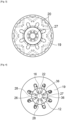
- Each cutout 30 has a drop-shaped cross-section (please see in particular Figure 2 ), the contour of each cutout 30 having two straight portions 32 and a curved portion 34.
- Straight portions 32 are provided for interaction with a mounting tool which defines the angular or circumferential position of each rotor plate 16 on rotor shaft 12.
- the angular position of cutouts 30 slightly differs among different types of rotor plates.
- cutouts 30 In view of the ability of cutouts 30 to form coolant passage 24, cutouts 30 have a comparatively large cross-section.
- cutouts 30 are arranged between adjacent recesses 20 which form the pockets for receiving the magnets so that waste heat generated in this portion of the rotor can very effectively be discharged towards the coolant flowing through coolant passages 24.
- the distance between the pocket formed by recesses 20 and coolant passage 24 formed by cutouts 30 is designated in Figure 2 with arrow A.
- Dashed line L shows that the radially outer end of cutouts 30 overlap with the radially inner ends of recesses 20, ensuring that the waste heat can be very effectively dissipated.
- rotor shaft 12 is provided with a plurality of radial coolant openings 36 which connect coolant passages 24 (via recesses 28) to outlet channels 26.
- a closed coolant path is formed by inlet channel 22, radial coolant openings 27, recesses 28, coolant passages 24, recesses 28, radial coolant openings 36 and outlet channels 26.
- recesses 28 are wider than coolant passages 24. It is therefore possible to use standardized endplates 18, 19 which do not have to perfectly match with their recesses 28 the circumferential position of coolant passages 24. The slight angular offset does not negatively affect the available cross-section for the coolant flow.
- FIG. 6 shows a second embodiment.
- the same reference numerals are used, and reference is made to the above comments.
- the inlet of the coolant path is formed by a combination of radially extending coolant openings 27 in rotor shaft 12 and an endplate 50.
- Endplate 50 is similar to endplate 19 in that it is axially held in rotor shaft 12 by a nut (not shown in Figure 6 ).
- endplate 50 (more precisely: the radially outer ends of recesses 28) forms a radial end for the radially extending portion of the coolant path so that the coolant path is diverted from a radial direction towards an axial direction into the cutouts of the rotor plates.
- annular groove 52 is provided at the radially inner end of endplate 50 on the side facing the rotor plates 16, with the radially outer surface 54 of groove 52 serving as the radial end of the coolant openings.
- Figure 8 shows a third embodiment.
- the same reference numerals are used, and reference is made to the above comments.
- endplate 18 can be provided with an annular groove instead of a plurality of the separate radial recesses.
- the outer radial end of the respective configuration (either circumferential wall of the groove or outer end of each recess) forms the radial end of the coolant opening and marks the diversion of the coolant from a radial flow direction towards an axial flow direction.
- FIG. 9 shows a fourth embodiment.
- the same reference numerals are used, and reference is made to the above comments.
- Coolant openings 27 extend through enlarged end portion 62 and terminate at the circumferential outer surface of end portion 62. There, they are closed by the inner circumferential surface of endplate 64.
Landscapes
- Engineering & Computer Science (AREA)
- Power Engineering (AREA)
- Iron Core Of Rotating Electric Machines (AREA)
- Motor Or Generator Cooling System (AREA)
Abstract
The invention provides a rotor (10) for an electric machine, in particular for an electric motor, the rotor (10) having a rotor shaft (12) and a plurality of rotor plates (16) mounted on the rotor shaft (12), the rotor plates (16) having cutouts (30) which form coolant channels (24) extending in an axial direction through the stack formed from the rotor plates (16), the rotor shaft (12) having an axial coolant opening (22), a plurality of radial coolant openings (27; 36) being provided which connect the axial coolant opening (22) in the rotor shaft (12) with the coolant channels (24) in the stack of rotor plates (16), the rotor (10) further having an endplate (18; 19, 50; 64) which forms a radial end for the radial coolant openings (27).
Description
- The invention relates to a rotor for an electric machine, in particular for an electric motor of the type which is used for driving vehicles. The vehicles can be in particular commercial vehicles or passenger cars driven either entirely with electric energy or hybrid vehicles. The invention further relates to an electric machine with such rotor.
- It is known that electric machines used for driving vehicles should be cooled in order to prevent that the waste heat generated during operation results in excessively high temperatures. It is known to guide a coolant (for example oil) through certain parts of the electric machines so as to transport the waste heat to an external heat exchanger where it is discharged towards the environment.
- Numerous designs of coolant paths are known in the prior art. The object of the invention is to provide a rotor for an electric machine in which the path for the coolant can be formed in a simple manner.
- In order to solve this object, the invention provides a rotor for an electric machine, in particular for an electric motor, the rotor having a rotor shaft and a plurality of rotor plates mounted on the rotor shaft, the rotor plates having cutouts which form coolant channels extending in an axial direction through the stack formed from the rotor plates, the rotor shaft having an axial coolant opening, a plurality of radial coolant openings being provided which connect the axial coolant opening in the rotor shaft with the coolant channels in the stack of rotor plates, the rotor further having at least an endplate which forms a radial end for the radial coolant openings. The endplates of the rotor are usually of sufficient thickness for mechanical reasons, namely to compress the rotor plates mounted in the rotor shaft. The volume of the endplates can be used to prolong or terminate a coolant path formed in the rotor shaft. No additional mechanical elements are necessary to this end. Further, the endplate can be easily machined to have the required configuration.
- Preferably, the endplate has a closed contact surface for abutting at the stack of rotor plates so that the entirety of rotor plates is evenly supported or compressed in an axial direction.
- According to the invention, the rotor shaft has a radially enlarged end portion forming a shoulder at which the stack of rotor plates abuts in an axial direction, the radial coolant openings extending through the end portion towards an outer circumference thereof. The enlarged end portion allows directly absorbing axial loads at the radially inner portion of the rotor plates and offers sufficient space for accommodating the radial coolant openings.
- In view of manufacturing ease, the end portion preferably has at least one connecting opening for connecting the coolant channels formed in the stack of rotor plates to the radial coolant openings in the end portion.
- The connecting opening can be generated easily by machining so as to form an annular groove in the end portion at the side facing the stack of rotor plates.
- In order to preserve a larger supporting area at the enlarged end portion, the connecting opening can be formed by a plurality of axially extending openings which connect the coolant channels in the stack of rotor plates to the radial coolant openings.
- In one embodiment, the endplate has an annular groove at its radially inner end on the side facing the stack of rotor plates, allowing to machine the endplate by turning.
- In an alternative embodiment, the endplate has a plurality of radial recesses at its radially inner end on the side facing the stack of rotor plates, thereby maintaining a higher resistance to bending loads as compared to an embodiment which uses an annular groove.
- In one embodiment of the invention, the rotor shaft has a radially enlarged end portion forming a shoulder at which the endplate abuts in an axial direction, the radial coolant openings being formed axially inwardly from the end portion. This design is advantageous in that only short coolant openings are required in the rotor shaft, with the diversion of the coolant path towards the rotor plates being achieved with the endplate.
- For achieving the desired axial compression of the rotor plates and to ensure that a coolant path formed in an axial direction through the stack of rotor plates is essentially without leakage, a clamping element is arranged on the rotor shaft for axially clamping the stack of rotor plates, in particular a clamping nut.
- The invention will be described with reference to embodiments which are shown in the enclosed drawings. In the drawings,
- [
Fig. 1 ] shows a schematic cross-section through a rotor according to a first embodiment of the invention, - [
Fig. 2 ] shows a plan view of part of a rotor plate used in the rotor ofFigure 1 , - [
Fig. 3 ] shows a schematic cross-section through the rotor ofFigure 1 along plane III-III, - [
Fig. 4 ] shows a cross-section along plane IV-IV ofFigure 1 , - [
Fig. 5 ] shows a schematic cross-section along plane V-V ofFigure 1 , - [
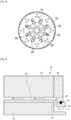
Fig. 6 ] schematically shows a second embodiment of the invention, - [
Fig. 7 ] schematically shows a top view of an endplate of an alternative to the second embodiment, - [
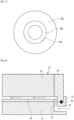
Fig. 8 ] schematically shows a third embodiment of the invention, and - [
Fig. 9 ] schematically shows a fourth embodiment of the invention. - In
Figure 1 , arotor 10 is shown which is used in an electric machine such as an electric motor. The motor can in particular be used to drive a vehicle such as a car or a truck, the vehicle been either entirely driven with electric energy or being a hybrid vehicle. -
Rotor 10 comprises arotor shaft 12, astack 14 ofrotor plates 16, and twoendplates stack 14 ofrotor plates 16 is held axially clamped betweenendplates - Each
rotor plate 16 has a plurality ofrecesses 20 which together with the recesses of axiallyadjacent rotor plates 16 form pockets for receiving magnets. The magnets are permanent magnets made from rare earth materials. It is also possible to use ferrite magnets. - In a manner known per se, the magnets are grouped in segments, with the angular position of the magnets in one segment slightly differing from the angular position of the magnets in an adjacent segment. This is advantageous regarding torque ripples and the reduction of noise.
-
Rotor 10 is provided with a coolant path which mainly consists of aninlet channel 22, a plurality ofcoolant passages 24 and a plurality ofoutlet channels 26. The coolant path is closed in that the coolant flow admitted intoinlet channel 22 exits throughoutlet channels 26. No coolant (apart from a very minor potential leakage flow) is discharged fromrotor 10 except for the entire coolant flow exiting throughoutlet channels 26. -
Inlet channel 22 is formed by an axial bore which extends through the majority ofrotor shaft 12. As can be seen inFigure 1 ,inlet channel 22 extends from one axial end ofrotor shaft 12 throughrotor shaft 12 to a position which is rearwardly of the end of the axial end ofstack 14 which is opposite to the side whereinlet channel 22 opens. In other words,inlet channel 22 is a blind bore extending approximately to the axial position where theleft endplate 18 inFigure 1 is arranged. - Close to the axial end of
inlet channel 22, a plurality of radially extendingcoolant openings 27 is provided inrotor shaft 12.Coolant openings 27 open on the outer circumferential surface ofrotor shaft 12 and are arranged inwardly of a shoulder formed by an radially enlarged end portion ofrotor shaft 12 at which endplate 18 abuts. -
Endplate 18 has a plurality of radially extendingrecesses 28 at its inner circumference. The position and the spacing ofrecesses 28 approximately coincides with the position ofradial coolant openings 27. -
Recesses 28 do not extend through theentire endplate respective endplate -
Recesses 28 serve for connecting the radially outer end ofcoolant openings 27 tocoolant passages 24 formed within thestack 14 ofrotor plates 16.Coolant passages 24 are formed from a plurality ofcutouts 30 formed in eachrotor plate 16. -
Endplate 18 thus serves as a radial end for the radial coolant openings formed from theradial coolant openings 27 inrotor shaft 12 and from therecesses 28. - Each
cutout 30 has a drop-shaped cross-section (please see in particularFigure 2 ), the contour of eachcutout 30 having twostraight portions 32 and acurved portion 34.Straight portions 32 are provided for interaction with a mounting tool which defines the angular or circumferential position of eachrotor plate 16 onrotor shaft 12. In order to achieve the slight angular offset of the pockets for the magnets over thestack 14 of rotor plates, the angular position ofcutouts 30 slightly differs among different types of rotor plates. In view of the ability ofcutouts 30 to formcoolant passage 24,cutouts 30 have a comparatively large cross-section. - Further,
cutouts 30 are arranged betweenadjacent recesses 20 which form the pockets for receiving the magnets so that waste heat generated in this portion of the rotor can very effectively be discharged towards the coolant flowing throughcoolant passages 24. The distance between the pocket formed byrecesses 20 andcoolant passage 24 formed bycutouts 30 is designated inFigure 2 with arrow A. - Dashed line L shows that the radially outer end of
cutouts 30 overlap with the radially inner ends ofrecesses 20, ensuring that the waste heat can be very effectively dissipated. - As can be seen in
Figure 1 andFigure 4 ,endplate 19 arranged at the end ofstack 14 ofrotor plates 16 which is adjacent to the open end ofinlet channel 22, is provided withrecesses 28 in a manner similar toendplate 18 arranged at the opposite end. - At the position of
recesses 28 inendplate 19,rotor shaft 12 is provided with a plurality ofradial coolant openings 36 which connect coolant passages 24 (via recesses 28) tooutlet channels 26. In this manner, a closed coolant path is formed byinlet channel 22,radial coolant openings 27, recesses 28,coolant passages 24, recesses 28,radial coolant openings 36 andoutlet channels 26. - In a manner similar to
endplate 18,endplate 19 also serves as a radial end of the coolant passage formed fromrecesses 28 andcoolant openings 36. - As can be seen in
Figures 4 and5 , recesses 28 are wider thancoolant passages 24. It is therefore possible to usestandardized endplates recesses 28 the circumferential position ofcoolant passages 24. The slight angular offset does not negatively affect the available cross-section for the coolant flow. - In order to reduce a leakage of coolant, seals can be used to seal between
endplate 18 and an radiallyenlarged end portion 13 onrotor shaft 12, betweenendplate 18 and theadjacent rotor plate 16, between adjacent rotor plates, betweenendplate 19 and theadjacent rotor plate 16 and betweenendplate 19 androtor shaft 12.Reference numeral 40 is used for designating potential positions of a seal or a sealing material. -
Figure 6 shows a second embodiment. For elements known from the first embodiment, the same reference numerals are used, and reference is made to the above comments. - In the embodiment of
Figure 6 , the inlet of the coolant path is formed by a combination of radially extendingcoolant openings 27 inrotor shaft 12 and anendplate 50.Endplate 50 is similar toendplate 19 in that it is axially held inrotor shaft 12 by a nut (not shown inFigure 6 ). Thus, endplate 50 (more precisely: the radially outer ends of recesses 28) forms a radial end for the radially extending portion of the coolant path so that the coolant path is diverted from a radial direction towards an axial direction into the cutouts of the rotor plates. - A
seal 40 is used for preventing leakage of the coolant. - An alternative to the second embodiment is shown in
Figure 7 . Instead of a plurality of separate recesses, anannular groove 52 is provided at the radially inner end ofendplate 50 on the side facing therotor plates 16, with the radiallyouter surface 54 ofgroove 52 serving as the radial end of the coolant openings. -
Figure 8 shows a third embodiment. For elements known from the first and second embodiments, the same reference numerals are used, and reference is made to the above comments. - The third embodiment largely corresponds to the first embodiment, with the difference being that
enlarged end portion 13 ofrotor shaft 12 andendplate 18 abutting at the shoulder formed byenlarged end portion 13, are here arranged at the "coolant inlet side" ofrotor shaft 12. - In a manner similar to the variant shown in
Figure 7 ,endplate 18 can be provided with an annular groove instead of a plurality of the separate radial recesses. In any case, the outer radial end of the respective configuration (either circumferential wall of the groove or outer end of each recess) forms the radial end of the coolant opening and marks the diversion of the coolant from a radial flow direction towards an axial flow direction. -
Figure 9 shows a fourth embodiment. For elements known from the previous embodiments, the same reference numerals are used, and reference is made to the above comments. - The difference between the fourth embodiment and the previous embodiments is that in the fourth embodiment, the axial support for the stack or
rotor plates 16 is composed of ashoulder 60 on a radiallyenlarged end portion 62 of therotor shaft 12, and anendplate 64 which is arranged on the outer circumference ofend portion 62. -
Coolant openings 27 extend throughenlarged end portion 62 and terminate at the circumferential outer surface ofend portion 62. There, they are closed by the inner circumferential surface ofendplate 64. -
Enlarged end portion 62 is provided at its side facing therotor plates 16 with a plurality of connectingopenings 66 which connectradial coolant openings 27 withcoolant passages 24. - As an alternative to separate connecting
openings 66, a circumferential groove could be used inshoulder 60 on the side facing therotor plates 16.
Claims (9)
- A rotor (10) for an electric machine, in particular for an electric motor, the rotor (10) having a rotor shaft (12) and a plurality of rotor plates (16) mounted on the rotor shaft (12), the rotor plates (16) having cutouts (30) which form coolant channels (24) extending in an axial direction through the stack formed from the rotor plates (16), the rotor shaft (12) having an axial coolant opening (22), a plurality of radial coolant openings (27; 36) being provided which connect the axial coolant opening (22) in the rotor shaft (12) with the coolant channels (24) in the stack of rotor plates (16), the rotor (10) further having an endplate (18; 19, 50; 64) which forms a radial end for the radial coolant openings (27),
wherein the rotor shaft (12) has a radially enlarged end portion (62) forming a shoulder (60) at which the stack of rotor plates (16) abuts in an axial direction, the radial coolant openings (27) extending through the end portion (62) towards an outer circumference thereof. - The rotor (10) of claim 1 wherein the endplate (64) has a closed contact surface for abutting at the stack of rotor plates (16).
- The rotor (10) of claim 1 wherein the end portion (62) has at least one connecting opening (66) for connecting the coolant channels (24) formed in the stack of rotor plates (16) to the radial coolant openings (27) in the end portion.
- The rotor (10) of claim 3 wherein the connecting opening (66) is formed by an annular groove in the end portion at the side facing the stack of rotor plates (16).
- The rotor (10) of claim 3 wherein the connecting opening (66) is formed by a plurality of axially extending openings which connect the coolant channels (24) in the stack of rotor plates (16) to the radial coolant openings (27).
- The rotor (10) of claim 1 wherein the endplate (50) has an annular groove (52) at its radially inner end on the side facing the stack of rotor plates (16).
- The rotor (10) of claim 1 wherein the endplate (18; 19; 50; 62) has a plurality of radial recesses (28) at its radially inner end on the side facing the stack of rotor plates (16).
- The rotor of claim 6 or claim 7 wherein the rotor shaft (12) has a radially enlarged end (13) portion forming a shoulder at which the endplate (18) abuts in an axial direction, the radial coolant openings (27) being formed axially inwardly from the end portion (13).
- The rotor (10) of claim 1 wherein a clamping element is arranged on the rotor shaft (12) for axially clamping the stack of rotor plates (16), in particular a clamping nut.
Applications Claiming Priority (1)
| Application Number | Priority Date | Filing Date | Title |
|---|---|---|---|
| FR2214106A FR3144440B1 (en) | 2022-12-21 | 2022-12-21 | Rotor for an electric machine, in particular for an electric motor |
Publications (1)
| Publication Number | Publication Date |
|---|---|
| EP4391316A1 true EP4391316A1 (en) | 2024-06-26 |
Family
ID=85685262
Family Applications (1)
| Application Number | Title | Priority Date | Filing Date |
|---|---|---|---|
| EP23213608.5A Pending EP4391316A1 (en) | 2022-12-21 | 2023-12-01 | Rotor for an electric machine, in particular for an electric motor |
Country Status (3)
| Country | Link |
|---|---|
| EP (1) | EP4391316A1 (en) |
| CN (1) | CN118232576A (en) |
| FR (1) | FR3144440B1 (en) |
Citations (4)
| Publication number | Priority date | Publication date | Assignee | Title |
|---|---|---|---|---|
| JPH04101255U (en) * | 1991-02-05 | 1992-09-01 | 東洋電機製造株式会社 | Rotor of fully enclosed rotating electric machine |
| JP2009219186A (en) * | 2008-03-07 | 2009-09-24 | Toyota Motor Corp | Rotor cooling structure |
| JP2012105487A (en) * | 2010-11-11 | 2012-05-31 | Komatsu Ltd | Cooling device for electric motor |
| DE112018004871T5 (en) * | 2017-09-06 | 2020-06-10 | Mitsubishi Electric Corporation | ELECTRIC ROTATION MACHINE |
-
2022
- 2022-12-21 FR FR2214106A patent/FR3144440B1/en active Active
-
2023
- 2023-12-01 EP EP23213608.5A patent/EP4391316A1/en active Pending
- 2023-12-20 CN CN202311765476.XA patent/CN118232576A/en active Pending
Patent Citations (4)
| Publication number | Priority date | Publication date | Assignee | Title |
|---|---|---|---|---|
| JPH04101255U (en) * | 1991-02-05 | 1992-09-01 | 東洋電機製造株式会社 | Rotor of fully enclosed rotating electric machine |
| JP2009219186A (en) * | 2008-03-07 | 2009-09-24 | Toyota Motor Corp | Rotor cooling structure |
| JP2012105487A (en) * | 2010-11-11 | 2012-05-31 | Komatsu Ltd | Cooling device for electric motor |
| DE112018004871T5 (en) * | 2017-09-06 | 2020-06-10 | Mitsubishi Electric Corporation | ELECTRIC ROTATION MACHINE |
Also Published As
| Publication number | Publication date |
|---|---|
| FR3144440B1 (en) | 2025-01-17 |
| FR3144440A1 (en) | 2024-06-28 |
| CN118232576A (en) | 2024-06-21 |
Similar Documents
| Publication | Publication Date | Title |
|---|---|---|
| US11418077B2 (en) | Rotor assembly with magnets and cooling channels and cooling channel separation element in the shaft | |
| US6469407B2 (en) | Electrical machine with a cooling device | |
| US11152827B2 (en) | End plate for a rotor assembly of an electrical machine, rotor assembly for an electrical machine, and vehicle | |
| US11177709B2 (en) | Rotor assembly for an electric machine, electric machine for a vehicle, and vehicle | |
| US9819247B2 (en) | Cooling jacket for an electric motor or generator having coolant inlet and outlets with opposite flow direction streams | |
| US3629628A (en) | Cooling arrangement for a squirrel cage rotor assembly | |
| US9169884B2 (en) | Wet brake assembly | |
| US20210281134A1 (en) | Electric machine | |
| US12407223B2 (en) | Electric machine and method for operating said machine | |
| US20240014705A1 (en) | Electric Axial Flux Machine, And Axle Comprising An Electric Drive | |
| US4877383A (en) | Device having a sealed control opening and an orbiting valve | |
| CN220067006U (en) | Stator core, driving motor and vehicle | |
| CN111095734A (en) | Stator, in particular of an electric machine of a motor vehicle, and method for producing such a stator | |
| EP4391316A1 (en) | Rotor for an electric machine, in particular for an electric motor | |
| CN114649885A (en) | Cooling device for cooling the stator of an electric motor | |
| US20240380266A1 (en) | Rotor arrangement for improved cooling of a rotor | |
| CN120153560A (en) | Electric wheel hub drive for motor vehicles | |
| CN118302934A (en) | Rotor assembly for electric motor and electric motor having the rotor assembly | |
| US20230344286A1 (en) | Stator of an electric machine and an electric machine | |
| EP1153225B1 (en) | Motor with symmetric braking system | |
| US20250096625A1 (en) | Stator | |
| CN101601179B (en) | Permanent magnet rotor with accommodating pockets, sealed by means of an adhesive film, for the permanent magnet | |
| CN113612323A (en) | Rotor for an electric machine | |
| CN117267138A (en) | fluid pump | |
| CN115347729B (en) | Dynamic balance plate, motor and vehicle |
Legal Events
| Date | Code | Title | Description |
|---|---|---|---|
| PUAI | Public reference made under article 153(3) epc to a published international application that has entered the european phase |
Free format text: ORIGINAL CODE: 0009012 |
|
| STAA | Information on the status of an ep patent application or granted ep patent |
Free format text: STATUS: REQUEST FOR EXAMINATION WAS MADE |
|
| 17P | Request for examination filed |
Effective date: 20231201 |
|
| AK | Designated contracting states |
Kind code of ref document: A1 Designated state(s): AL AT BE BG CH CY CZ DE DK EE ES FI FR GB GR HR HU IE IS IT LI LT LU LV MC ME MK MT NL NO PL PT RO RS SE SI SK SM TR |
|
| RAP1 | Party data changed (applicant data changed or rights of an application transferred) |
Owner name: VALEO ELECTRIFICATION |