EP4391313A1 - Rotor, electric machine and vehicle - Google Patents
Rotor, electric machine and vehicle Download PDFInfo
- Publication number
- EP4391313A1 EP4391313A1 EP23218521.5A EP23218521A EP4391313A1 EP 4391313 A1 EP4391313 A1 EP 4391313A1 EP 23218521 A EP23218521 A EP 23218521A EP 4391313 A1 EP4391313 A1 EP 4391313A1
- Authority
- EP
- European Patent Office
- Prior art keywords
- rotor
- end plate
- mounting grooves
- electric machine
- slot
- Prior art date
- Legal status (The legal status is an assumption and is not a legal conclusion. Google has not performed a legal analysis and makes no representation as to the accuracy of the status listed.)
- Pending
Links
Images



Classifications
-
- H—ELECTRICITY
- H02—GENERATION; CONVERSION OR DISTRIBUTION OF ELECTRIC POWER
- H02K—DYNAMO-ELECTRIC MACHINES
- H02K1/00—Details of the magnetic circuit
- H02K1/06—Details of the magnetic circuit characterised by the shape, form or construction
- H02K1/22—Rotating parts of the magnetic circuit
- H02K1/27—Rotor cores with permanent magnets
- H02K1/2706—Inner rotors
- H02K1/272—Inner rotors the magnetisation axis of the magnets being perpendicular to the rotor axis
- H02K1/274—Inner rotors the magnetisation axis of the magnets being perpendicular to the rotor axis the rotor consisting of two or more circumferentially positioned magnets
- H02K1/2753—Inner rotors the magnetisation axis of the magnets being perpendicular to the rotor axis the rotor consisting of two or more circumferentially positioned magnets the rotor consisting of magnets or groups of magnets arranged with alternating polarity
- H02K1/276—Magnets embedded in the magnetic core, e.g. interior permanent magnets [IPM]
- H02K1/2766—Magnets embedded in the magnetic core, e.g. interior permanent magnets [IPM] having a flux concentration effect
-
- H—ELECTRICITY
- H02—GENERATION; CONVERSION OR DISTRIBUTION OF ELECTRIC POWER
- H02K—DYNAMO-ELECTRIC MACHINES
- H02K1/00—Details of the magnetic circuit
- H02K1/06—Details of the magnetic circuit characterised by the shape, form or construction
- H02K1/22—Rotating parts of the magnetic circuit
- H02K1/32—Rotating parts of the magnetic circuit with channels or ducts for flow of cooling medium
-
- H—ELECTRICITY
- H02—GENERATION; CONVERSION OR DISTRIBUTION OF ELECTRIC POWER
- H02K—DYNAMO-ELECTRIC MACHINES
- H02K1/00—Details of the magnetic circuit
- H02K1/06—Details of the magnetic circuit characterised by the shape, form or construction
- H02K1/22—Rotating parts of the magnetic circuit
- H02K1/27—Rotor cores with permanent magnets
- H02K1/2706—Inner rotors
- H02K1/272—Inner rotors the magnetisation axis of the magnets being perpendicular to the rotor axis
- H02K1/274—Inner rotors the magnetisation axis of the magnets being perpendicular to the rotor axis the rotor consisting of two or more circumferentially positioned magnets
- H02K1/2753—Inner rotors the magnetisation axis of the magnets being perpendicular to the rotor axis the rotor consisting of two or more circumferentially positioned magnets the rotor consisting of magnets or groups of magnets arranged with alternating polarity
- H02K1/276—Magnets embedded in the magnetic core, e.g. interior permanent magnets [IPM]
-
- H—ELECTRICITY
- H02—GENERATION; CONVERSION OR DISTRIBUTION OF ELECTRIC POWER
- H02K—DYNAMO-ELECTRIC MACHINES
- H02K9/00—Arrangements for cooling or ventilating
- H02K9/19—Arrangements for cooling or ventilating for machines with closed casing and closed-circuit cooling using a liquid cooling medium, e.g. oil
Definitions
- the present disclosure relates to a rotor for an electric machine, an electric machine comprising the rotor, and a vehicle.
- An electric machine is an apparatus capable of accomplishing electromechanical energy conversion, and is widely used in the automotive field.
- An electric machine generally comprises a stator, a rotor, windings and magnets, etc.
- High temperatures will develop in an electric machine during operation, e.g. during high-speed operation, and these high temperatures will cause demagnetization of the magnets. This will affect the stability and reliability of the electric machine, and in severe cases, the electric machine will need to be replaced.
- the rotor of an electric machine will split into layers, and this will also affect the stability and reliability of the electric machine, e.g. the NVH performance of the electric machine, i.e. noise, vibration and harshness, and may even cause the electric machine to fail.
- magnet mounting grooves for mounting magnets in the rotors of commonly used electric machines are generally filled with resin, for the purpose of fixing the magnets and increasing heat conduction between the magnets and the rotor laminations.
- An electric machine designed in this way can generally only be cooled at the exterior of the rotor and the rotor shaft. Thus, the rotor cannot be cooled effectively, and the magnets disposed inside the rotor cannot be cooled.
- the objective of the present disclosure is to provide an electric machine rotor and an electric machine, the rotor having a fluid cooling system, which can achieve effective cooling of the rotor, and in particular the rotor interior and the magnets.
- the present disclosure relates to a rotor for an electric machine, the rotor comprising:
- the fluid cooling system further comprises an opening disposed on a wall of the rotor shaft, the opening being in fluid communication with the slot, and a cooling medium being able to flow from the opening into the cooling medium channel.
- the cooling medium is recovered after sequentially flowing through the opening, the slot, the gap and the through-hole.
- the slot extends outwards from an inner edge of the corresponding end plate and at least partly covers the gap.
- slots and through-holes arranged alternately are provided on each of the first end plate and second end plate.
- the slots and through-holes of at least one of the first end plate and second end plate are arranged equidistantly in the circumferential direction of the corresponding end plate.
- the magnet mounting grooves comprise multiple groups of mounting slots which are radially offset, the slot and the through-hole being respectively aligned with gaps of the multiple groups of mounting slots.
- the slot extends radially outwards in a tapering manner.
- the magnets are disposed in the magnet mounting groovess by snap-fitting.
- the present disclosure further relates to an electric machine, comprising a stator and the rotor described above.
- the present disclosure further relates to a vehicle comprising the electric machine described above.
- the technical solution of the present disclosure has the following advantages: by providing the fluid cooling system for the rotor, efficient cooling of the rotor interior and magnets can be achieved; by using a bidirectional fluid configuration for cooling, cooling efficiency can be increased.
- the electric machine and rotor of the present disclosure can avoid magnet demagnetization caused by high temperatures and splitting of the rotor into layers due to high rotation speeds at high temperatures, thus having improved stability and reliability and achieving higher power.
- the electric machine of the present disclosure may comprise a rotor and a stator as shown in Fig. 1 .
- the electric machine may be used for a new energy vehicle, and comprises a stator, a rotor, windings and magnets, etc. disposed in a cavity thereof.
- the rotor comprises a rotor shaft 1, a rotor body 2, a first end plate 6 and a second end plate 7.
- the rotor further comprises multiple magnets 4.
- the rotor shaft 1 has a rotation axis A.
- the rotor body 2 is fixed to the rotor shaft 1 and formed of multiple stacked laminations, and magnet mounting grooves 3 are provided in the rotor body 2.
- the magnet mounting grooves extend substantially in a direction parallel to the rotation axis A.
- the multiple magnets 4 are disposed in the magnet mounting grooves 3, and a gap 5 is formed between each magnet and an inner wall of the corresponding magnet mounting grooves 3. Specifically, in a direction perpendicular to the rotation axis A, i.e.
- gaps 5 are formed between the inner wall of the magnet mounting grooves 3 and each of two sides of the magnet 4.
- the magnet mounting grooves 3 are no longer filled with resin; the magnets 4 are disposed in the magnet mounting grooves 3 by snap-fitting for example. In this way, the magnet can be fixed while also ensuring that there are gaps 5 between the magnet mounting grooves 3 and the magnet 4.
- the first end plate 6 and second end plate 7 are respectively disposed at two ends of the rotor body 2 along the rotation axis A.
- the rotor of the present disclosure further comprises a fluid cooling system for itself, the fluid cooling system comprising slots 8, through-holes 9, and the gaps 5 described above.
- the slots 8 are disposed on one of the first end plate 6 and second end plate 7, and located on the side of this end plate that faces towards the rotor body 2.
- the through-holes 9 are disposed on the other of the first end plate 6 and second end plate 7.
- slots 8 and through-holes 9 arranged alternately are provided on each of the first end plate 6 and second end plate 7.
- the slots 8 on the first end plate 6 correspond to the through-holes 9 on the second end plate 7, and the through-holes 9 on the first end plate 6 correspond to the slots on the second end plate 7.
- the slots 8, the gaps 5 and the through-holes 9 are in fluid communication to form cooling medium channels.
- slots and through-holes on the same end plate are not arranged alternately.
- the fluid cooling system further comprises an opening 10 disposed on a wall of the rotor shaft 1, the opening being in fluid communication with the slot 8, and a cooling medium being able to flow from the opening 10 into the cooling medium channel.
- the cooling medium is an electrically non-conductive medium, and may be oil; the cooling oil is pumped by a pump into the cavity of the electric machine from a gearbox and flows into an internal cavity of the rotor shaft 1, then flows from the opening 10 into the rotor interior, so as to cool the rotor interior.
- the cooling medium flows from the opening 10 near the first end plate 6 into the slot 8 on the first end plate 6, then flows into the gap 5 in communication therewith, and then flows out of the rotor through the through-hole 9 on the second end plate 7, thereby cooling the rotor interior and magnets, as shown by the black arrow in Fig. 4 .
- the cooling medium may also flow from the opening 10 near the second end plate 7 into the slot 8 on the second end plate 7, then flow into the gap 5 in communication therewith, and then flow out of the rotor through the through-hole 9 on the first end plate 6; cooling of the rotor interior and magnets may also be achieved in this way.
- the circulation direction of the cooling medium in the second circulation configuration is essentially opposite to the circulation direction of the cooling medium in the first circulation configuration. It should be noted that the cooling medium may circulate in both of the circulation configurations described above at the same time. By employing such a configuration with circulation in both directions, a larger cooling area can be achieved, for efficient cooling of the rotor interior and magnets.
- the cooling medium is recovered after sequentially flowing through the opening 10, the slot 8, the gap 5 and the through-hole 9.
- the cooling medium may be recovered into a cooling medium circulation system of the electric machine.
- the cooling medium is recovered into a cooling oil circulation system of a gearbox.
- the cooling medium flowing out of the through-hole 9 on the first end plate 6 or second end plate 7 flows to the bottom of a housing of the electric machine system, and is then recovered to the gearbox.
- the slot 8 extends outwards from an inner edge of the corresponding end plate and at least partly covers the gap 5.
- the inner edge of the end plate is an edge of the end plate that is located at the inside in a radial direction, or an edge of the end plate that is near the rotor shaft.
- the slot 8 by covering part of the gap 5, the slot 8 achieves fluid communication with the gap 5, thus enabling unhindered circulation of the cooling medium.
- the slots 8 and through-holes 9 of at least one of the first end plate 6 and second end plate 7 are arranged equidistantly in the circumferential direction of the corresponding end plate.
- the slots 8 and through-holes 9 on both the first end plate 6 and second end plate 7 are arranged equidistantly in the circumferential direction of the corresponding end plate. This depends on the arrangement of magnets in the rotor interior. Of course, arrangement at non-equal intervals in the circumferential direction is also possible, as long as the slots and through-holes correspond to the gaps in a direction parallel to the rotation axis A.
- the magnet mounting grooves 3 comprise multiple groups of mounting slots which are radially offset.
- Fig. 7 shows two groups of mounting slots, wherein mounting slots of the same group are substantially located on a circumference at the same distance from the rotation axis.
- a first group of magnet mounting grooves 31 is arranged substantially radially inward of a second group of magnet mounting grooves 32.
- adjacent magnet mounting grooves in the same group of mounting slots form a substantially V-shaped arrangement.
- a V-shaped arrangement formed by two magnet mounting grooves in the first group of magnet mounting grooves 31 is substantially parallel to a V-shaped arrangement formed by two magnet mounting grooves in the second group of magnet mounting grooves 32.
- the radially extending slots 8 and through-holes 9 are respectively aligned with the gaps of the multiple groups of mounting slots, so as to achieve fluid communication. In this way, it is possible to achieve larger magnet mounting grooves, and a larger area of coincidence of the slots and through-holes with the magnet mounting grooves; as shown in Fig. 6 , this means that the fluid circulation cross section can be larger.
- the slots 8 may extend radially outwards in a tapering manner. This is because the multiple groups of mounting slots which are radially offset have different-sized gaps, so there is no need to provide slots of radially uniform size.
- the rotor of the electric machine of the present disclosure has a fluid cooling system, which can achieve cooling of the rotor, and in particular the rotor interior and magnets.
- the rotor of the electric machine of the present disclosure can increase the cooling efficiency.
- the present disclosure can solve the problems of magnet demagnetization caused by high temperatures and splitting of the rotor into layers due to high rotation speeds at high temperatures, such that the electric machine has improved stability and reliability.
- the power of the electric machine with effective rotor cooling of the present disclosure can be increased, e.g. by 20% to 30%.
- a vehicle comprising the electric machine mentioned above.
- the vehicle may be an electrified vehicle, such as a battery electric vehicle (BEV), a hybrid electric vehicle (HEV), a plug-in hybrid electric vehicle (PHEV), a range extended EV and a fuel cell electric vehicle (FCEV).
- BEV battery electric vehicle
- HEV hybrid electric vehicle
- PHEV plug-in hybrid electric vehicle
- FCEV fuel cell electric vehicle
- the vehicle may also be a hydrogen-powered vehicle.
Landscapes
- Engineering & Computer Science (AREA)
- Power Engineering (AREA)
- Iron Core Of Rotating Electric Machines (AREA)
- Permanent Field Magnets Of Synchronous Machinery (AREA)
Abstract
Description
- The present disclosure relates to a rotor for an electric machine, an electric machine comprising the rotor, and a vehicle.
- An electric machine is an apparatus capable of accomplishing electromechanical energy conversion, and is widely used in the automotive field. An electric machine generally comprises a stator, a rotor, windings and magnets, etc. High temperatures will develop in an electric machine during operation, e.g. during high-speed operation, and these high temperatures will cause demagnetization of the magnets. This will affect the stability and reliability of the electric machine, and in severe cases, the electric machine will need to be replaced. In addition, at high rotation speeds at high temperatures, the rotor of an electric machine will split into layers, and this will also affect the stability and reliability of the electric machine, e.g. the NVH performance of the electric machine, i.e. noise, vibration and harshness, and may even cause the electric machine to fail.
- At present, magnet mounting grooves for mounting magnets in the rotors of commonly used electric machines are generally filled with resin, for the purpose of fixing the magnets and increasing heat conduction between the magnets and the rotor laminations. An electric machine designed in this way can generally only be cooled at the exterior of the rotor and the rotor shaft. Thus, the rotor cannot be cooled effectively, and the magnets disposed inside the rotor cannot be cooled.
- Therefore, it would be desirable if any improvement for an electric machine in which the rotor interior and the magnets can be cooled effectively.
- The objective of the present disclosure is to provide an electric machine rotor and an electric machine, the rotor having a fluid cooling system, which can achieve effective cooling of the rotor, and in particular the rotor interior and the magnets.
- This objective is achieved by means of the rotor and the electric machine comprising same according to the present disclosure, which are described below.
- The present disclosure relates to a rotor for an electric machine, the rotor comprising:
- a rotor shaft, having a rotation axis;
- a rotor body, fixed to the rotor shaft and formed of multiple stacked laminations, wherein magnet mounting grooves are provided in the rotor body;
- multiple magnets disposed in the magnet mounting grooves, with a gap formed between each magnet and an inner wall of the corresponding magnet mounting grooves;
- a first end plate and a second end plate, respectively disposed at two ends of the rotor body along the rotation axis,
- wherein the rotor further comprises a fluid cooling system, the fluid cooling system comprising:
- a slot, disposed on one of the first end plate and second end plate, and located on a side of this end plate that faces towards the rotor body;
- a through-hole, disposed on the other of the first end plate and second end plate; and
- the gap,
- and wherein the slot, the gap and the through-hole are in fluid communication to form a cooling medium channel.
- In an embodiment, the fluid cooling system further comprises an opening disposed on a wall of the rotor shaft, the opening being in fluid communication with the slot, and a cooling medium being able to flow from the opening into the cooling medium channel.
- In an embodiment, the cooling medium is recovered after sequentially flowing through the opening, the slot, the gap and the through-hole.
- In an embodiment, the slot extends outwards from an inner edge of the corresponding end plate and at least partly covers the gap.
- In an embodiment, slots and through-holes arranged alternately are provided on each of the first end plate and second end plate.
- In an embodiment, the slots and through-holes of at least one of the first end plate and second end plate are arranged equidistantly in the circumferential direction of the corresponding end plate.
- In an embodiment, the magnet mounting grooves comprise multiple groups of mounting slots which are radially offset, the slot and the through-hole being respectively aligned with gaps of the multiple groups of mounting slots.
- In an embodiment, the slot extends radially outwards in a tapering manner.
- In an embodiment, the magnets are disposed in the magnet mounting groovess by snap-fitting.
- The present disclosure further relates to an electric machine, comprising a stator and the rotor described above.
- The present disclosure further relates to a vehicle comprising the electric machine described above.
- The technical solution of the present disclosure has the following advantages: by providing the fluid cooling system for the rotor, efficient cooling of the rotor interior and magnets can be achieved; by using a bidirectional fluid configuration for cooling, cooling efficiency can be increased. Thus, the electric machine and rotor of the present disclosure can avoid magnet demagnetization caused by high temperatures and splitting of the rotor into layers due to high rotation speeds at high temperatures, thus having improved stability and reliability and achieving higher power.
-
-
Fig. 1 is a schematic drawing of a rotor for an electric machine according to an embodiment of the present disclosure. -
Fig. 2 is a schematic drawing of part of a rotor for an electric machine according to an embodiment of the present disclosure. -
Fig. 3 is a schematic drawing of part of a rotor for an electric machine according to an embodiment of the present disclosure, viewed from another direction. -
Fig. 4 is a schematic sectional drawing of part of a rotor for an electric machine according to an embodiment of the present disclosure. -
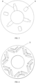
Fig. 5 is a schematic drawing of an end plate of a rotor for an electric machine according to another embodiment of the present disclosure. -
Fig. 6 is a schematic drawing of a rotor body and an end plate of a rotor for an electric machine according to another embodiment of the present disclosure. -
Fig. 7 is a schematic drawing of a rotor body of a rotor for an electric machine according to another embodiment of the present disclosure. - In order to clarify the objective, technical solution and advantages of embodiments of the present disclosure, the technical solution of embodiments of the present disclosure is described clearly and completely below in conjunction with the drawings accompanying embodiments of the present disclosure.
- Unless otherwise defined, technical terms or scientific terms used herein shall have the common meanings understood by those skilled in the art. The words "first", "second", and the like used in the Description and claims of the patent application disclosed herein do not indicate any order, quantity or importance, being merely used to distinguish different component parts. Likewise, "a", "one", "the" or similar words do not indicate a quantity limit, but mean at least one. "Comprises" or "includes" and similar words mean that the element or object appearing before the word encompasses the elements or objects and their equivalents listed after the word, without excluding other elements or objects.
- The electric machine of the present disclosure may comprise a rotor and a stator as shown in
Fig. 1 . The electric machine may be used for a new energy vehicle, and comprises a stator, a rotor, windings and magnets, etc. disposed in a cavity thereof. The rotor comprises arotor shaft 1, arotor body 2, afirst end plate 6 and asecond end plate 7. In addition, as shown inFig. 7 , the rotor further comprisesmultiple magnets 4. - As shown in
Fig. 2 , therotor shaft 1 has a rotation axis A. Therotor body 2 is fixed to therotor shaft 1 and formed of multiple stacked laminations, andmagnet mounting grooves 3 are provided in therotor body 2. The magnet mounting grooves extend substantially in a direction parallel to the rotation axis A. As shown inFigs. 4 and7 , themultiple magnets 4 are disposed in themagnet mounting grooves 3, and agap 5 is formed between each magnet and an inner wall of the correspondingmagnet mounting grooves 3. Specifically, in a direction perpendicular to the rotation axis A, i.e. in a radial direction of the rotor,gaps 5 are formed between the inner wall of themagnet mounting grooves 3 and each of two sides of themagnet 4. In the rotor of the present disclosure, themagnet mounting grooves 3 are no longer filled with resin; themagnets 4 are disposed in themagnet mounting grooves 3 by snap-fitting for example. In this way, the magnet can be fixed while also ensuring that there aregaps 5 between themagnet mounting grooves 3 and themagnet 4. - As shown in
Fig. 1 , thefirst end plate 6 andsecond end plate 7 are respectively disposed at two ends of therotor body 2 along the rotation axis A. - The rotor of the present disclosure further comprises a fluid cooling system for itself, the fluid cooling
system comprising slots 8, through-holes 9, and thegaps 5 described above. As shown inFigs. 2 - 5 , theslots 8 are disposed on one of thefirst end plate 6 andsecond end plate 7, and located on the side of this end plate that faces towards therotor body 2. The through-holes 9 are disposed on the other of thefirst end plate 6 andsecond end plate 7. As shown inFigs. 2 and3 ,slots 8 and through-holes 9 arranged alternately are provided on each of thefirst end plate 6 andsecond end plate 7. In a direction parallel to the extension axis A, theslots 8 on thefirst end plate 6 correspond to the through-holes 9 on thesecond end plate 7, and the through-holes 9 on thefirst end plate 6 correspond to the slots on thesecond end plate 7. Theslots 8, thegaps 5 and the through-holes 9 are in fluid communication to form cooling medium channels. Of course, it is also possible that slots and through-holes on the same end plate are not arranged alternately. - As shown in
Figs. 2 and3 , the fluid cooling system further comprises anopening 10 disposed on a wall of therotor shaft 1, the opening being in fluid communication with theslot 8, and a cooling medium being able to flow from theopening 10 into the cooling medium channel. The cooling medium is an electrically non-conductive medium, and may be oil; the cooling oil is pumped by a pump into the cavity of the electric machine from a gearbox and flows into an internal cavity of therotor shaft 1, then flows from theopening 10 into the rotor interior, so as to cool the rotor interior. - As a result of providing the fluid cooling system located substantially in the rotor interior, effective cooling of the rotor interior and magnets can be achieved by means of the cooling medium, reducing the rotor temperature, and avoiding the problems of magnet demagnetization caused by high temperatures and splitting of the rotor into layers due to high rotation speeds at high temperatures.
- For example, the cooling medium flows from the
opening 10 near thefirst end plate 6 into theslot 8 on thefirst end plate 6, then flows into thegap 5 in communication therewith, and then flows out of the rotor through the through-hole 9 on thesecond end plate 7, thereby cooling the rotor interior and magnets, as shown by the black arrow inFig. 4 . The cooling medium may also flow from theopening 10 near thesecond end plate 7 into theslot 8 on thesecond end plate 7, then flow into thegap 5 in communication therewith, and then flow out of the rotor through the through-hole 9 on thefirst end plate 6; cooling of the rotor interior and magnets may also be achieved in this way. The circulation direction of the cooling medium in the second circulation configuration is essentially opposite to the circulation direction of the cooling medium in the first circulation configuration. It should be noted that the cooling medium may circulate in both of the circulation configurations described above at the same time. By employing such a configuration with circulation in both directions, a larger cooling area can be achieved, for efficient cooling of the rotor interior and magnets. - For example, the cooling medium is recovered after sequentially flowing through the
opening 10, theslot 8, thegap 5 and the through-hole 9. The cooling medium may be recovered into a cooling medium circulation system of the electric machine. For example, the cooling medium is recovered into a cooling oil circulation system of a gearbox. Specifically, the cooling medium flowing out of the through-hole 9 on thefirst end plate 6 orsecond end plate 7 flows to the bottom of a housing of the electric machine system, and is then recovered to the gearbox. - As shown in
Figs. 5 and 6 , theslot 8 extends outwards from an inner edge of the corresponding end plate and at least partly covers thegap 5. The inner edge of the end plate is an edge of the end plate that is located at the inside in a radial direction, or an edge of the end plate that is near the rotor shaft. As shown inFig. 6 , by covering part of thegap 5, theslot 8 achieves fluid communication with thegap 5, thus enabling unhindered circulation of the cooling medium. - As shown in
Fig. 5 , theslots 8 and through-holes 9 of at least one of thefirst end plate 6 andsecond end plate 7 are arranged equidistantly in the circumferential direction of the corresponding end plate. In the case of circulation in both directions, theslots 8 and through-holes 9 on both thefirst end plate 6 andsecond end plate 7 are arranged equidistantly in the circumferential direction of the corresponding end plate. This depends on the arrangement of magnets in the rotor interior. Of course, arrangement at non-equal intervals in the circumferential direction is also possible, as long as the slots and through-holes correspond to the gaps in a direction parallel to the rotation axis A. - As shown in
Fig. 7 , themagnet mounting grooves 3 comprise multiple groups of mounting slots which are radially offset.Fig. 7 shows two groups of mounting slots, wherein mounting slots of the same group are substantially located on a circumference at the same distance from the rotation axis. For example, a first group ofmagnet mounting grooves 31 is arranged substantially radially inward of a second group ofmagnet mounting grooves 32. In addition, adjacent magnet mounting grooves in the same group of mounting slots form a substantially V-shaped arrangement. A V-shaped arrangement formed by two magnet mounting grooves in the first group ofmagnet mounting grooves 31 is substantially parallel to a V-shaped arrangement formed by two magnet mounting grooves in the second group ofmagnet mounting grooves 32. As shown inFig. 5 , theradially extending slots 8 and through-holes 9 are respectively aligned with the gaps of the multiple groups of mounting slots, so as to achieve fluid communication. In this way, it is possible to achieve larger magnet mounting grooves, and a larger area of coincidence of the slots and through-holes with the magnet mounting grooves; as shown inFig. 6 , this means that the fluid circulation cross section can be larger. - Again referring to
Figs. 5 and 6 , theslots 8 may extend radially outwards in a tapering manner. This is because the multiple groups of mounting slots which are radially offset have different-sized gaps, so there is no need to provide slots of radially uniform size. - The rotor of the electric machine of the present disclosure has a fluid cooling system, which can achieve cooling of the rotor, and in particular the rotor interior and magnets. In addition, by using a bidirectional circulation configuration to perform cooling, the rotor of the electric machine of the present disclosure can increase the cooling efficiency. Thus, the present disclosure can solve the problems of magnet demagnetization caused by high temperatures and splitting of the rotor into layers due to high rotation speeds at high temperatures, such that the electric machine has improved stability and reliability. Further, compared with a watercooled electric machine, the power of the electric machine with effective rotor cooling of the present disclosure can be increased, e.g. by 20% to 30%.
- According to another aspect of the present disclosure, a vehicle is proposed, comprising the electric machine mentioned above. The vehicle may be an electrified vehicle, such as a battery electric vehicle (BEV), a hybrid electric vehicle (HEV), a plug-in hybrid electric vehicle (PHEV), a range extended EV and a fuel cell electric vehicle (FCEV). The vehicle may also be a hydrogen-powered vehicle.
- It should be understood that the structures described above and shown in the drawings are only examples of the present disclosure, which may be replaced by other structures exhibiting the same or similar functions for obtaining the desired end result. In addition, it should be understood that an embodiment described above and shown in the drawings should be deemed to merely constitute a non-restrictive example of the present disclosure, and that it may be modified in various manners within the scope defined by the claims.
Claims (11)
- A rotor for an electric machine, characterized in that the rotor comprises:a rotor shaft (1), having a rotation axis (A);a rotor body (2), fixed to the rotor shaft (1) and formed of multiple stacked laminations, wherein magnet mounting grooves (3) are provided in the rotor body (2);a plurality of magnets (4) disposed in the magnet mounting grooves (3), with a gap (5) formed between each magnet and an inner wall of the corresponding magnet mounting grooves;a first end plate (6) and a second end plate (7), respectively disposed at two ends of the rotor body (2) along the rotation axis (A),wherein the rotor further comprises a fluid cooling system, the fluid cooling system comprising:a slot (8), disposed on one of the first end plate (6) and second end plate (7), and located on a side of the end plate that faces towards the rotor body (2);a through-hole (9), disposed on the other of the first end plate (6) and second end plate (7); andthe gap (5),and wherein the slot (8), the gap (5) and the through-hole (9) are in fluid communication to form a cooling medium channel.
- The rotor according to claim 1, characterized in that the fluid cooling system further comprises an opening (10) disposed on a wall of the rotor shaft (1), the opening being in fluid communication with the slot (8), and a cooling medium being able to flow from the opening (10) into the cooling medium channel.
- The rotor according to claim 2, characterized in that the cooling medium is recovered after sequentially flowing through the opening (10), the slot (8), the gap (5) and the through-hole (9).
- The rotor according to claim 2, characterized in that the slot (8) extends outwards from an inner edge of the corresponding end plate and at least partly covers the gap (5).
- The rotor according to any one of claims 1 to 4, characterized in that slots (8) and through-holes (9) arranged alternately are provided on each of the first end plate (6) and second end plate (7).
- The rotor according to claim 5, characterized in that the slots (8) and through-holes (9) of at least one of the first end plate (6) and second end plate (7) are arranged equidistantly in the circumferential direction of the corresponding end plate.
- The rotor according to any one of claims 1 to 4, characterized in that the magnet mounting grooves (3) comprise multiple groups of mounting grooves which are radially offset, the slot (8) and the through-hole (9) being respectively aligned with gaps of the multiple groups of mounting grooves.
- The rotor according to claim 7, characterized in that the slot (8) extends radially outwards in a tapering manner.
- The rotor according to any one of claims 1 to 4, characterized in that the magnets (4) are disposed in the magnet mounting grooves (3) by snap-fitting.
- An electric machine, characterized by comprising a stator and the rotor according to any one of claims 1 to 9.
- A vehicle, characterized by comprising the electric machine according to Claim 10.
Applications Claiming Priority (1)
| Application Number | Priority Date | Filing Date | Title |
|---|---|---|---|
| CN202211650679.XA CN118232574A (en) | 2022-12-21 | 2022-12-21 | Rotor and motor |
Publications (1)
| Publication Number | Publication Date |
|---|---|
| EP4391313A1 true EP4391313A1 (en) | 2024-06-26 |
Family
ID=89224510
Family Applications (1)
| Application Number | Title | Priority Date | Filing Date |
|---|---|---|---|
| EP23218521.5A Pending EP4391313A1 (en) | 2022-12-21 | 2023-12-20 | Rotor, electric machine and vehicle |
Country Status (3)
| Country | Link |
|---|---|
| US (1) | US20240213836A1 (en) |
| EP (1) | EP4391313A1 (en) |
| CN (1) | CN118232574A (en) |
Citations (3)
| Publication number | Priority date | Publication date | Assignee | Title |
|---|---|---|---|---|
| EP1953896A1 (en) * | 2005-11-09 | 2008-08-06 | Kabushiki Kaisha Toshiba | Rotor for electric rotating machine and electric rotating machine |
| WO2021105631A1 (en) * | 2019-11-29 | 2021-06-03 | Nidec Psa Emotors | Liquid-cooled electrical machine |
| US20220399770A1 (en) * | 2019-11-14 | 2022-12-15 | Nidec Psa Emotors | Liquid cooling machine |
Family Cites Families (8)
| Publication number | Priority date | Publication date | Assignee | Title |
|---|---|---|---|---|
| JP4492745B2 (en) * | 2008-10-27 | 2010-06-30 | トヨタ自動車株式会社 | Rotating electric machine |
| JP5445675B2 (en) * | 2010-04-23 | 2014-03-19 | 株式会社Ihi | Rotating machine |
| WO2019008820A1 (en) * | 2017-07-05 | 2019-01-10 | 三菱電機株式会社 | Rotating electric machine |
| JP7131123B2 (en) * | 2018-06-22 | 2022-09-06 | 日本電産株式会社 | rotor and motor |
| DE102018118275A1 (en) * | 2018-07-27 | 2020-01-30 | Valeo Siemens Eautomotive Germany Gmbh | Rotor assembly for an electric machine, electric machine for a vehicle and vehicle |
| DE102019200098A1 (en) * | 2019-01-07 | 2020-07-09 | Audi Ag | Fluid-cooled rotor for an electrical machine |
| KR102172262B1 (en) * | 2019-01-25 | 2020-10-30 | 엘지전자 주식회사 | Electric motor |
| US11626776B2 (en) * | 2020-05-08 | 2023-04-11 | Dana Belgium N.V. | Methods and systems for oil cooled rotor laminations |
-
2022
- 2022-12-21 CN CN202211650679.XA patent/CN118232574A/en active Pending
-
2023
- 2023-12-20 US US18/390,723 patent/US20240213836A1/en active Pending
- 2023-12-20 EP EP23218521.5A patent/EP4391313A1/en active Pending
Patent Citations (3)
| Publication number | Priority date | Publication date | Assignee | Title |
|---|---|---|---|---|
| EP1953896A1 (en) * | 2005-11-09 | 2008-08-06 | Kabushiki Kaisha Toshiba | Rotor for electric rotating machine and electric rotating machine |
| US20220399770A1 (en) * | 2019-11-14 | 2022-12-15 | Nidec Psa Emotors | Liquid cooling machine |
| WO2021105631A1 (en) * | 2019-11-29 | 2021-06-03 | Nidec Psa Emotors | Liquid-cooled electrical machine |
Also Published As
| Publication number | Publication date |
|---|---|
| US20240213836A1 (en) | 2024-06-27 |
| CN118232574A (en) | 2024-06-21 |
Similar Documents
| Publication | Publication Date | Title |
|---|---|---|
| KR102787421B1 (en) | Stator for an electric machine, electric machine, motor vehicle | |
| EP4236036B1 (en) | Motor, power assembly and apparatus | |
| US11303174B2 (en) | Rotor for an electric machine | |
| CN111769673A (en) | A motor rotor, motor and automobile | |
| US9906103B2 (en) | Rotary electrical machine cooling apparatus | |
| US20120025642A1 (en) | Rotating electric machine | |
| CN110784038A (en) | Rotor assembly for motor, motor for vehicle and vehicle | |
| US12362614B2 (en) | Rotor for an axial flux motor | |
| US8860276B2 (en) | Electromagnetic steel sheet formed body, rotor core, rotor, rotating electrical machine, and vehicle | |
| JP7112340B2 (en) | Rotor of rotating electric machine and rotating electric machine | |
| US20240120784A1 (en) | Rotor, motor, powertrain, and vehicle | |
| CN113193703A (en) | Motor shell assembly | |
| US20240356401A1 (en) | Rotor and Electric Machine With Integrated Winding Head Cooling, Manufacturing Method and Motor Vehicle | |
| US20160226355A1 (en) | Magnetic inductor electric motor | |
| JP2010226841A (en) | Rotating electric machine | |
| US11349370B2 (en) | Rotary electric machine with shrink-fitted bearing | |
| EP4391313A1 (en) | Rotor, electric machine and vehicle | |
| US12081074B2 (en) | Stator cooling assembly for electric machine | |
| US20210273500A1 (en) | Electrified vehicle electric machine stator | |
| EP2918003B1 (en) | Method and device for liquid cooling of an electric motor | |
| CN120569879A (en) | Rotor assembly | |
| CN112968546B (en) | Rotor assembly and self-starting permanent magnet synchronous reluctance motor | |
| WO2022127823A1 (en) | Motor component, motor, motor vehicle and assembly method of motor component | |
| US20240055913A1 (en) | Electric machine having shoulders between a plurality of conductors and tabs of a winding receptacle region of a stator or of a rotor | |
| CN223912336U (en) | Dual rotor motors and vehicle power systems |
Legal Events
| Date | Code | Title | Description |
|---|---|---|---|
| PUAI | Public reference made under article 153(3) epc to a published international application that has entered the european phase |
Free format text: ORIGINAL CODE: 0009012 |
|
| STAA | Information on the status of an ep patent application or granted ep patent |
Free format text: STATUS: THE APPLICATION HAS BEEN PUBLISHED |
|
| AK | Designated contracting states |
Kind code of ref document: A1 Designated state(s): AL AT BE BG CH CY CZ DE DK EE ES FI FR GB GR HR HU IE IS IT LI LT LU LV MC ME MK MT NL NO PL PT RO RS SE SI SK SM TR |
|
| STAA | Information on the status of an ep patent application or granted ep patent |
Free format text: STATUS: REQUEST FOR EXAMINATION WAS MADE |
|
| 17P | Request for examination filed |
Effective date: 20241220 |
|
| STAA | Information on the status of an ep patent application or granted ep patent |
Free format text: STATUS: EXAMINATION IS IN PROGRESS |
|
| 17Q | First examination report despatched |
Effective date: 20260331 |