EP4391310A1 - Electric motor - Google Patents
Electric motor Download PDFInfo
- Publication number
- EP4391310A1 EP4391310A1 EP23216440.0A EP23216440A EP4391310A1 EP 4391310 A1 EP4391310 A1 EP 4391310A1 EP 23216440 A EP23216440 A EP 23216440A EP 4391310 A1 EP4391310 A1 EP 4391310A1
- Authority
- EP
- European Patent Office
- Prior art keywords
- conductive body
- insulator
- electric motor
- post
- core
- Prior art date
- Legal status (The legal status is an assumption and is not a legal conclusion. Google has not performed a legal analysis and makes no representation as to the accuracy of the status listed.)
- Pending
Links
Images







Classifications
-
- H—ELECTRICITY
- H02—GENERATION; CONVERSION OR DISTRIBUTION OF ELECTRIC POWER
- H02K—DYNAMO-ELECTRIC MACHINES
- H02K3/00—Details of windings
- H02K3/46—Fastening of windings on the stator or rotor structure
- H02K3/52—Fastening salient pole windings or connections thereto
- H02K3/521—Fastening salient pole windings or connections thereto applicable to stators only
- H02K3/522—Fastening salient pole windings or connections thereto applicable to stators only for generally annular cores with salient poles
-
- H—ELECTRICITY
- H02—GENERATION; CONVERSION OR DISTRIBUTION OF ELECTRIC POWER
- H02K—DYNAMO-ELECTRIC MACHINES
- H02K1/00—Details of the magnetic circuit
- H02K1/06—Details of the magnetic circuit characterised by the shape, form or construction
- H02K1/12—Stationary parts of the magnetic circuit
- H02K1/18—Means for mounting or fastening magnetic stationary parts on to, or to, the stator structures
-
- H—ELECTRICITY
- H02—GENERATION; CONVERSION OR DISTRIBUTION OF ELECTRIC POWER
- H02K—DYNAMO-ELECTRIC MACHINES
- H02K1/00—Details of the magnetic circuit
- H02K1/06—Details of the magnetic circuit characterised by the shape, form or construction
- H02K1/12—Stationary parts of the magnetic circuit
- H02K1/14—Stator cores with salient poles
- H02K1/146—Stator cores with salient poles consisting of a generally annular yoke with salient poles
- H02K1/148—Sectional cores
-
- H—ELECTRICITY
- H02—GENERATION; CONVERSION OR DISTRIBUTION OF ELECTRIC POWER
- H02K—DYNAMO-ELECTRIC MACHINES
- H02K11/00—Structural association of dynamo-electric machines with electric components or with devices for shielding, monitoring or protection
- H02K11/0094—Structural association with other electrical or electronic devices
-
- H—ELECTRICITY
- H02—GENERATION; CONVERSION OR DISTRIBUTION OF ELECTRIC POWER
- H02K—DYNAMO-ELECTRIC MACHINES
- H02K15/00—Processes or apparatus specially adapted for manufacturing, assembling, maintaining or repairing of dynamo-electric machines
- H02K15/30—Manufacture of winding connections
- H02K15/33—Connecting winding sections; Forming leads; Connecting leads to terminals
-
- H—ELECTRICITY
- H02—GENERATION; CONVERSION OR DISTRIBUTION OF ELECTRIC POWER
- H02K—DYNAMO-ELECTRIC MACHINES
- H02K3/00—Details of windings
- H02K3/04—Windings characterised by the conductor shape, form or construction, e.g. with bar conductors
- H02K3/28—Layout of windings or of connections between windings
-
- H—ELECTRICITY
- H02—GENERATION; CONVERSION OR DISTRIBUTION OF ELECTRIC POWER
- H02K—DYNAMO-ELECTRIC MACHINES
- H02K3/00—Details of windings
- H02K3/32—Windings characterised by the shape, form or construction of the insulation
- H02K3/34—Windings characterised by the shape, form or construction of the insulation between conductors or between conductor and core, e.g. slot insulation
- H02K3/345—Windings characterised by the shape, form or construction of the insulation between conductors or between conductor and core, e.g. slot insulation between conductor and core, e.g. slot insulation
-
- H—ELECTRICITY
- H02—GENERATION; CONVERSION OR DISTRIBUTION OF ELECTRIC POWER
- H02K—DYNAMO-ELECTRIC MACHINES
- H02K2203/00—Specific aspects not provided for in the other groups of this subclass relating to the windings
- H02K2203/03—Machines characterised by the wiring boards, i.e. printed circuit boards or similar structures for connecting the winding terminations
-
- H—ELECTRICITY
- H02—GENERATION; CONVERSION OR DISTRIBUTION OF ELECTRIC POWER
- H02K—DYNAMO-ELECTRIC MACHINES
- H02K2203/00—Specific aspects not provided for in the other groups of this subclass relating to the windings
- H02K2203/09—Machines characterised by wiring elements other than wires, e.g. bus rings, for connecting the winding terminations
Definitions
- the present disclosure relates to electric motors, and more specifically to stators for electric motors.
- a stator assembly for an electric motor can be formed from a plurality of annular stator segments arranged into a tubular shape.
- a bus bar assembly can be formed separately from the stator assembly and then subsequently coupled to the stator assembly.
- a printed circuit board assembly can be coupled to the bus bar assembly.
- an electric motor including a rotor assembly including a rotor shaft defining a rotational axis.
- the electric motor also includes a stator assembly including a core, an insulator at least partially covering the core, and a plurality of windings, the insulator defining one of a post that protrudes in an axial direction parallel with the rotational axis or a receptacle in which the post is receivable.
- the electric motor further includes a bus bar assembly including a non-conductive body and a plurality of conductors configured to make an electrical connection between at least two windings of the plurality of windings, the non-conductive body including the other of the post or the receptacle.
- the receptacle includes at least one of an aperture or a recess, and the post is received within the receptacle to secure the non-conductive body to the insulator.
- the techniques described herein relate to an electric motor, wherein the non-conductive body includes a radially protruding arm, and wherein the one of the post or the receptacle is defined by the radially protruding arm.
- the techniques described herein relate to an electric motor, wherein the receptacle includes an aperture and is defined by the non-conductive body, and wherein the post extends entirely through the aperture between a first axially facing surface of the non-conductive body and an opposite, second axially facing surface of the non-conductive body.
- the techniques described herein relate to an electric motor, wherein the post is cylindrical.
- the techniques described herein relate to an electric motor, wherein the receptacle is defined by the non-conductive body and includes a recess that extends only partially through the non-conductive body in an axial direction.
- the techniques described herein relate to an electric motor, wherein the non-conductive body further defines a relief aperture that communicates with the recess, and wherein a shoulder is defined between the recess and the relief aperture.
- the techniques described herein relate to an electric motor, further including a printed circuit board assembly (PCBA) defining a mounting aperture, and wherein the non-conductive body further defines a mounting post that is received by the mounting aperture to secure the PCBA to the non-conductive body.
- PCBA printed circuit board assembly
- the techniques described herein relate to an electric motor, further including a rotor bearing that rotatably supports the rotor shaft, wherein the non-conductive body further defines a bearing pocket that receives and supports the rotor bearing.
- the techniques described herein relate to an electric motor, wherein the core is a first core and the insulator is a first insulator, and wherein the stator assembly includes a plurality of stator segments including a first stator segment and a second stator segment positioned adjacent the first stator segment in a circumferential direction, and wherein the first stator segment includes the first core, the first insulator, and a first winding of the plurality of windings, and wherein the second stator segment includes a second core, a second insulator, and a second winding of the plurality of windings.
- the techniques described herein relate to an electric motor, wherein the receptacle is a first receptacle of a plurality of receptacles defined by the non-conductive body, and wherein the post is a first post defined by the first insulator, and wherein the second insulator defines a second post that is received by a second receptacle of the plurality of receptacles to secure the non-conductive body to the second insulator.
- the techniques described herein relate to an electric motor, wherein the post and the receptacle are made from a thermoplastic material that melts in response to being heated above a melt temperature and bonds in response to being subsequently cooled below the melt temperature to affix the non-conductive body to the insulator.
- an electric motor including a rotor assembly including a rotor shaft.
- the electric motor also includes a stator assembly including a core, an insulator at least partially covering the core, and a plurality of windings.
- the electric motor further includes a bus bar assembly including a non-conductive body and a plurality of conductors configured to make an electrical connection between at least two windings of the plurality of windings, the non-conductive body defining a mounting post.
- the electric motor also includes a printed circuit board assembly (PCBA) defining a mounting aperture that receives the mounting post to secure the PCBA to the non-conductive body.
- PCBA printed circuit board assembly
- the techniques described herein relate to an electric motor, wherein the non-conductive body defines an annular recess that receives the PCBA.
- the techniques described herein relate to an electric motor, wherein the PCBA includes a circular peripheral edge and a mounting arm that protrudes radially from the circular peripheral edge, and wherein the mounting arm defines the mounting aperture.
- the techniques described herein relate to an electric motor, wherein the non-conductive body further defines a locating protrusion that protrudes into the annular recess, and wherein the PCBA includes a circular peripheral edge and a locating notch that interrupts the circular peripheral edge, and wherein the locating notch receives the locating protrusion.
- the techniques described herein relate to an electric motor, wherein the insulator defines an insulator post that protrudes axially away from the core, and wherein the non-conductive body defines a receptacle that receives the insulator post to secure the non-conductive body to the insulator, the receptacle including at least one of an aperture or a recess.
- the techniques described herein relate to an electric motor, wherein the core is a first core and the insulator is a first insulator, and wherein the stator assembly includes a plurality of stator segments including a first stator segment and a second stator segment positioned adjacent the first stator segment in a circumferential direction, and wherein the first stator segment includes the first core, the first insulator, and a first winding of the plurality of windings, and wherein the second stator segment includes a second core, a second insulator, and a second winding of the plurality of windings.
- the present disclosure provides, in another aspect, a method of assembling an electric motor, the method including providing a rotor assembly including a rotor shaft.
- the method also includes providing a stator assembly including a core, an insulator at least partially covering the core, and a plurality of windings.
- the method further includes providing a bus bar assembly including a non-conductive body and a plurality of conductors.
- the method also includes ultrasonically welding the non-conductive body to the insulator.
- the method further includes making an electrical connection between at least two windings of the plurality of windings and the plurality of conductors.
- the techniques described herein relate to a method, wherein the non-conductive body includes an inboard surface facing toward the insulator, and wherein the insulator includes a coil protector portion having an axially outer surface, and wherein ultrasonically welding the non-conductive body to the insulator produces an ultrasonic weld located where the inboard surface contacts the axially outer surface.
- the techniques described herein relate to a method, further including inserting a bearing within a bearing pocket of the non-conductive body, wherein the bearing pocket defines an outer circumferential surface, and wherein the insulator includes a coil protector portion having an inner annular surface, and wherein ultrasonically welding the non-conductive body to the insulator produces an ultrasonic weld located where the outer circumferential surface contacts the inner annular surface.
- an electric motor comprising:
- the non-conductive body may include a radially protruding arm, and wherein the one of the post or the receptacle may be defined by the radially protruding arm.
- the receptacle may comprise an aperture and may be defined by the non-conductive body, and wherein the post may extend entirely through the aperture between a first axially facing surface of the non-conductive body and an opposite, second axially facing surface of the non-conductive body.
- the post may be cylindrical.
- the receptacle may be defined by the non-conductive body and may comprise a recess that extends only partially through the non-conductive body in an axial direction.
- the non-conductive body may further define a relief aperture that communicates with the recess, and wherein a shoulder may be defined between the recess and the relief aperture.
- the electric motor may further comprise a printed circuit board assembly (PCBA) defining a mounting aperture, and wherein the non-conductive body may further define a mounting post that may be received by the mounting aperture to secure the PCBA to the non-conductive body.
- PCBA printed circuit board assembly
- the electric motor may further comprise a rotor bearing that rotatably supports the rotor shaft, wherein the non-conductive body may further define a bearing pocket that receives and supports the rotor bearing.
- the core may be a first core and the insulator may be a first insulator
- the stator assembly may comprise a plurality of stator segments including a first stator segment and a second stator segment positioned adjacent the first stator segment in a circumferential direction, and wherein the first stator segment includes the first core, the first insulator, and a first winding of the plurality of windings, and wherein the second stator segment includes a second core, a second insulator, and a second winding of the plurality of windings.
- the receptacle may be a first receptacle of a plurality of receptacles defined by the non-conductive body, and wherein the post may be a first post defined by the first insulator, and wherein the second insulator may define a second post that may be received by a second receptacle of the plurality of receptacles to secure the non-conductive body to the second insulator.
- the post and the receptacle may be made from a thermoplastic material that melts in response to being heated above a melt temperature and bonds in response to being subsequently cooled below the melt temperature to affix the non-conductive body to the insulator.
- an electric motor comprising:
- the non-conductive body may define an annular recess that receives the PCBA.
- the PCBA may include a circular peripheral edge and a mounting arm that protrudes radially from the circular peripheral edge, and wherein the mounting arm may define the mounting aperture.
- the non-conductive body may further define a locating protrusion that protrudes into the annular recess, and wherein the PCBA may include a circular peripheral edge and a locating notch that interrupts the circular peripheral edge, and wherein the locating notch may receive the locating protrusion.
- the insulator may define an insulator post that protrudes axially away from the core, and wherein the non-conductive body may define a receptacle that receives the insulator post to secure the non-conductive body to the insulator, the receptacle comprising at least one of an aperture or a recess.
- the core may be a first core and the insulator may be a first insulator
- the stator assembly comprises a plurality of stator segments including a first stator segment and a second stator segment positioned adjacent the first stator segment in a circumferential direction, and wherein the first stator segment includes the first core, the first insulator, and a first winding of the plurality of windings, and wherein the second stator segment includes a second core, a second insulator, and a second winding of the plurality of windings.
- the techniques described herein relate to a method of assembling an electric motor, the method comprising:
- the non-conductive body may include an inboard surface facing toward the insulator, and wherein the insulator may include a coil protector portion having an axially outer surface, and wherein ultrasonically welding the non-conductive body to the insulator produces an ultrasonic weld located where the inboard surface contacts the axially outer surface.
- the method may further comprise inserting a bearing within a bearing pocket of the non-conductive body, wherein the bearing pocket defines an outer circumferential surface, and wherein the insulator includes a coil protector portion having an inner annular surface, and wherein ultrasonically welding the non-conductive body to the insulator produces an ultrasonic weld located where the outer circumferential surface contacts the inner annular surface.
- FIG. 1 and 2 illustrate a power tool 10 such as, e.g., a drill, a rotary impact tool, and the like.
- the power tool 10 includes a housing 12 and an electric motor 14.
- the power tool 10 is operable with a battery pack 16 removably coupled to a battery receptacle 18 located at a bottom end of the housing 12.
- the battery pack 16 includes a plurality of battery cells (not shown), which are electrically connected to provide the desired output (e.g., nominal voltage, current capacity, etc.) of the battery pack 16.
- the electric motor 14 receives power from the battery pack 16 when the battery pack 16 is coupled to the battery receptacle 18.
- the power tool 10 may include a power cord for electrically connecting the motor 14 to a source of AC power.
- the battery pack 16 is the preferred means for powering the power tool 10, however, because a cordless power tool can be used in locations where other power sources are unavailable.
- the illustrated motor 14 is a brushless direct current (“BLDC") motor with a stator assembly 20 and a rotor assembly 22 that is rotatable with respect to the stator assembly 20 about an axis 24.
- the rotor assembly 22 includes a rotor body 26 and a fan 28 that are each supported on a rotor shaft 30.
- the fan 28 is located adjacent a first end or front end 32 of the motor 14.
- the stator assembly 20 includes a central cavity 34 that receives the rotor assembly 22 for rotation about the axis 24.
- the motor 14 also includes a bus bar assembly 36 and a printed circuit board assembly (PCBA) 38 that are each coupled to the stator assembly 20 at a second end or rear end 40 of the motor 14 opposite the front end 32.
- PCBA printed circuit board assembly
- the stator assembly 20 is a segmented stator assembly 20 including, in the illustrated embodiment, six stator segments 42 arranged within a tubular housing 44.
- Each stator segment 42 includes a core 46, a molded insulator 48, and a stator winding 50. Adjacent stator segments 42 are interconnected to each other with a notch and protrusion interlock 52.
- each stator segment 42 includes a longitudinally extending notch 54 provided in a first circumferential end face 56, and a longitudinally extending protrusion 58 protruding from a second circumferential end face 60.
- the notch 54 of one stator segment 42 receives the protrusion 58 of the adjacent stator segment 42 to align two adjacent stator segments 42.
- the tubular housing 44 surrounds the arranged stator segments 42 to fix the stator segments 42 together.
- the tubular housing 44 includes a tubular wall 62 that defines an inner cavity 64, and the stator segments 42 are received into the inner cavity 64 such that the tubular wall 62 converges about the stator segments 42.
- the tubular housing 44 can be heated to expand an outside diameter of the tubular wall 62, and then the tubular housing 44 can be pressed onto the stator segments 42. As the tubular housing 44 cools, the tubular wall 62 contracts about the stator segments 42 to secure the assembly.
- the tubular housing 44 also includes mounting tabs 66 extending radially outward from the tubular wall 62, with each mounting tab 66 defining a mounting aperture 68 configured to receive a fastener (e.g., a screw) for securing the motor 14 to, e.g., a gearcase (not shown).
- a fastener e.g., a screw
- each molded insulator 48 includes a mounting portion 70 protruding toward the rear end 40 of the motor 14.
- Each mounting portion 70 defines an axially extending threaded bore 72 that receives a first fastener 74 or a second fastener 76 to secure the bus bar assembly 36 and the PCBA 38 to the stator assembly 20 ( FIGS. 3 and 4 ).
- the bus bar assembly 36 includes three annular conductors 78 generally extending circumferentially about the motor 14, and a non-conductive body 80 that fixedly supports the conductors 78.
- Each conductor 78 includes two tangs 82 provided at opposite ends of the conductor 78, and a terminal 84 extending in the axial direction of the motor 14.
- Each terminal 84 mechanically and electrically connects to the PCBA 38.
- the PCBA 38 includes a plurality of apertures 85 ( FIGS. 3 and 12 ) corresponding to the locations of the terminals 84. During assembly, the terminals 84 are inserted into the apertures 85 and soldered to the PCBA 38 to mechanically and electrically connect the terminals 84 to the PCBA 38.
- Each stator winding 50 includes a pair of leads 86 ( FIG. 8 ) that connect to the adjacent tangs 82 of the conductors 78.
- the leads 86 can be soldered or fused to the tangs 82.
- the conductors 78 electrically connect the stator windings 50 to the PCBA 38.
- the PCBA 38 receives power from the battery pack 16 and selectively applies electrical current to the windings 50 to thereby cause the rotor shaft 30 to rotate about the axis 24.
- the non-conductive body 80 includes a central hub 88 that defines a central aperture or bearing pocket 90 that receives and supports a rotor bearing 92 ( FIGS. 10-12 ).
- the rotor bearing 92 receives the rotor shaft 30 to rotatably support the rotor assembly 22.
- the non-conductive body 80 further includes radial arms 94 that extend radially outward from the central hub 88.
- the number of radial arms 94 corresponds to the number of mounting portions 70 of the stator assembly 20.
- the non-conductive body includes six radial arms 94 that correspond to the six mounting portions 70 of the six stator segments 42.
- Each radial arm 94 defines a first aperture 96 that aligns with the threaded bore 72 of the corresponding mounting portion 70.
- the bus bar assembly 36 is secured to the mounting portions 70 of the stator assembly 20 by the first fasteners 74 and the second fasteners 76
- the PCBA 38 is secured to the stator assembly 20 by the second fasteners 76.
- the PCBA 38 includes second apertures 98 extending through the PCBA 38 and corresponding to the first apertures 96 of every other radial arm 94 in the circumferential direction.
- the radial arms 94 include first radial arms 94a and second radial arms 94b. The first radial arms 94a are coupled directly to the mounting portions 70 by the first fasteners 74.
- the second radial arms 94b are coupled to both the mounting portions 70 and the PCBA 38 by the second fasteners 76. More specifically, the first fasteners 74 are received through the first apertures 96 of the first radial arms 94a and tighten into the threaded bores 72 to secure the first radial arms 94a to the mounting portions 70. The second fasteners 76 are received through the second apertures 98 of the PCBA 38 and through the first apertures 96 of the second radial arms 94b, and tighten into the threaded bores to secure both the PCBA 38 and the second radial arms 94 to the mounting portions 70. As such, the bus bar assembly 36 is secured to each mounting portion 70 of each stator segment 42, and supports the rotor bearing 92 to center the rotor assembly 22 with respect to the stator assembly 20.
- the PCBA 38 includes a printed circuit board (PCB) 95 and a heat sink 97 secured to the PCB 95.
- the heat sink 97 includes a plurality of recesses 97a
- the non-conductive body 80 includes a plurality of axially extending protrusions 80a that are received within the corresponding recesses 97a to align the PCBA 38 with the bus bar assembly 36.
- FIGS. 13-16 illustrate a stator assembly 120 according to another embodiment of the disclosure.
- the stator assembly 120 is similar to the stator assembly 20 described above and includes much of the same structure as the stator assembly 20. And, the stator assembly 120 is operable with each the rotor assembly 22, the bus bar assembly 36, and the PCBA 38 described above.
- Features and elements of the stator assembly 120 that are similar to the features and elements of the stator assembly 20 are assigned the same reference numerals "plus 100.” It should be understood that the features of the stator assembly 120 that are not explicitly described below have the same properties as the features of the stator assembly 20.
- the stator assembly 120 couples to the bus bar assembly 36 and the PCBA 38 via the first fasteners 74 and the second fasteners 76 in the same manner as described above in connection with the stator assembly 20.
- the stator assembly 120 similarly includes stator segments 142 arranged end to end.
- the stator assembly 120 does not include a tubular housing. Instead, the stator segments 142 are laser welded at notch and protrusion interlocks 152 to secure the stator segments 142 together.
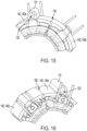
- the stator segments 142 are not uniform, but instead include first stator segments 142a and second stator segments 142b arranged in an alternating order ( FIGS. 15 and 16 ).
- each first stator segment 142a is connected to a second stator segment 142b at each circumferential end.
- the first stator segments 142a each include a mounting rib 121 protruding radially outward and extending lengthwise in the axial direction.
- Each mounting rib 121 defines a mounting aperture 123 that receives a fastener for mounting the stator assembly 120 to, e.g., a gearcase (not shown).
- the second stator segments 142b do not include mounting ribs, but do include axially extending grooves that receive a portion of the molded insulator 148.
- FIGS. 17-22 illustrate all or portions of an electric motor 1014 according to another embodiment of the disclosure.
- the motor 1014 includes the segmented stator assembly 120 described herein in connection with FIGS. 13-16 , and is operable with the rotor assembly 22 described herein in connection with FIGS. 2-4 and 12 .
- the motor 1014 includes a bus bar assembly 1036 that couples to an axial end of the stator assembly 120.
- the bus bar assembly 1036 includes three annular conductors 1078 ( FIGS. 21-22 ) and a non-conductive body 1080 that fixedly supports the conductors 1078.
- Each conductor 1078 includes four winding connection terminals or tangs 1082 provided at two opposite ends of the conductor 1078, and a power connection terminal 1084 protruding from the conductor 1078.
- the non-conductive body 1080 includes three mounting arms 1094 protruding radially from a central region of the non-conductive body 1080 and spaced at equal intervals about the circumference thereof.
- the mounting arms 1094 engage mounting portions 170 defined by the molded insulators 148 of the first stator segments 142a.
- the mounting arms 1094 can be secured to the mounting portions 170 via, e.g., threaded fasteners.
- Each terminal 1084 electrically connects to a PCBA (e.g., via wires; not shown) that receives power from the battery pack 16 ( FIG. 1 ) and selectively applies electrical current to the stator windings 150.
- the leads 186 of the windings 150 connect to the two adjacent tangs 1082 of the conductors 1078. In this way, the conductors 1078 electrically connect the stator windings 150 to the PCBA.
- the non-conductive body 1080 defines a central aperture or bearing pocket 1090 that receives the rotor bearing 92 ( FIG. 3 ).
- the rotor bearing 92 receives the rotor shaft 30 of the rotor assembly 22 ( FIG. 3 ) to rotatably support the rotor assembly 22. Since the bus bar assembly 1036 is secured to each mounting portion 170 of each stator segment 142a, and further supports the rotor bearing 92, the bus bar assembly 1036 centers the rotor assembly 22 with respect to the stator assembly 120.
- a printed circuit board assembly (PCBA) 1039 such as a rotor position sensor circuit board, is coupled to the non-conductive body 1080 of the bus bar assembly 1036.
- the PCBA 1039 is generally annular in shape and received into a corresponding centrally located, annularly shaped recess 1041 defined in the non-conductive body 1080 and secured thereto by threaded fasteners.
- the PCBA 1039 covers at least a portion of the bearing pocket 1090.
- the non-conductive body 1080 includes a first axial surface 1023 extending at a first axial end thereof and a second axial surface 1025 extending at a second axial end thereof.
- the first axial surface 1023 faces toward the stator assembly 120 and the second axial surface 1025 faces away from the stator assembly 120.
- the non-conductive body 1080 also includes a circumferential outer surface 1043 that extends between the first and second axial surfaces 1023, 1025.
- the tangs 1082 each protrude from the circumferential outer surface 1043 generally in the radial direction.
- Each tang 1082 includes a forked tip 1045 at its distal end and is generally planar in shape.
- the corresponding lead 186 ( FIG.
- each of the tangs 1082 are also generally located within the same axial region of the motor 1014.
- each tang 1082 lies within and defines a first plane 1031 that extends perpendicular to the central axis 1024.
- the tangs 1082 are spaced at generally equal intervals about the circumference of the non-conductive body 1080. As such, an angle A is measured on center about the central axis 1024 between any two adjacent tangs 1082.
- the bus bar assembly 1036 includes twelve tangs 1082 and the angle A is approximately 30 degrees.
- the bus bar assembly 1036 includes three power connection terminals 1084 that protrude from the second axial surface 1025 of the non-conductive body 1080 in an axial direction 1037.
- Each terminal 1084 is formed as a straight leg oriented perpendicular to the central axis 1024. All of the terminals 1084 extend generally parallel to one another and perpendicular to the first plane 1031.
- the bus bar assembly 1036 is configured to provide a parallel delta winding configuration for the motor 1014. Specifically, when the leads 186 of the windings 150 forming each coil are connected to the corresponding forked tips 1045 of the respective nearest tangs 1082, the windings 150 are arranged in a parallel delta winding configuration.
- FIGS. 23-32 illustrate alternative embodiments of electric motors that are similar to the electric motor 1014 described herein, but which utilize alternative means of securing the bus bar assembly to the stator assembly. The alternative means described in connections with FIGS. 23-32 do not use threaded fasteners.
- FIGS. 23-25 illustrate portions of an electric motor 1014a according to another embodiment of the disclosure.
- the motor 1014a includes a segmented stator assembly 120a similar to the segmented stator assembly 120 described herein in connection with FIGS. 13-16 .
- the motor 1014a also includes a bus bar assembly 1036a similar to the bus bar assembly 1036 described herein in connection with FIGS. 17-22 .
- the bus bar assembly 1036a may be secured to the stator assembly 120a by an ultrasonic welding process as will be described herein.
- the electric motor 1014a is operable with and may include the rotor assembly 22 described herein in connection with FIGS. 2-4 and 12 .
- the stator assembly 120a is a segmented stator assembly 120a including, in the illustrated embodiment, six stator segments 143a secured to one another at their circumferential ends.
- Each stator segment 143a includes a core 146a, a molded insulator 148a affixed to the core 146a (e.g., formed of resin via injection molding), and a stator winding 150a.
- the stator assembly may not be segmented, but instead may include a unitary annular core and a unitary insulator, while still utilizing the ultrasonic welding process to attach the bus bar assembly 1036a as described herein.
- the bus bar assembly 1036a includes a plurality of conductors 1078a with radially protruding winding connection terminals or tangs 1082a. Each stator winding 150a includes a pair of leads 186a that connect to the adjacent tangs 1082a.
- the bus bar assembly 1036a also includes a non-conductive body 1080a (e.g., formed of resin) that fixedly supports the conductors 1078a.
- a PCBA 1039a such as a rotor position sensor circuit board, is coupled to the non-conductive body 1080a.
- the non-conductive body 1080a further defines a central aperture or bearing pocket (e.g., such as bearing pocket 1090a, FIG. 25 ) that receives a rotor bearing 92 ( FIGS. 10-12 ).
- FIG. 24 shows a portion of the bus bar assembly 1036a secured to the stator assembly 120a by ultrasonic welding.
- the molded insulator 148a may be formed from a first thermoplastic material and the non-conductive body 1080a may also be formed of a second thermoplastic material.
- the first and second thermoplastic materials may be the same or different.
- Each of the first and second thermoplastic materials may experience melting when heated above their respective melt temperatures and may bond to one another when cooled.
- the parts are vibrated at high frequencies to generate heat that locally melts and fuses the parts together at the contacting surfaces 175a, 1075a.
- An ultrasonic weld is formed where a bottom or inboard surface 1075a of the non-conductive body 26 contacts an axially outer surface 175a of a coil protector portion 174a of the molded insulator 148a.
- FIG. 25 shows a second example of ultrasonic welding where the ultrasonic welds are formed at different locations. Specifically, the welds are formed where an outer circumferential surface 1079a of the bearing pocket 1090a contacts an inner annular surface 179a of the coil protection portions 174a.
- FIGS. 26-28 illustrate portions of an electric motor 1014b according to another embodiment of the disclosure.
- the electric motor 1014b is similar in many respects to the electric motor 1014a described herein in connection with FIGS. 23-25 , and as such, the following description will focus on the differences between the motors 1014a and 1014b.
- a bus bar assembly 1036b is secured to a stator assembly 120b via a thermal press method.
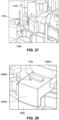
- a molded insulator 148b of the stator assembly 120b includes a plurality of elongated, axially protruding posts 170b.
- a non-conductive body 1080b of the bus bar assembly 1036b includes a plurality of radially protruding tabs or radial arms 1094b that each define receptacles configured as slot-shaped apertures 1095b shaped and sized to closely receive the posts 170b.
- At least the posts 170b may be formed from a first thermoplastic material and the receptacles or apertures 1095b may be defined by a second thermoplastic material.
- the first and second thermoplastic materials may be the same or different. Each of the first and second thermoplastic materials may experience melting when heated above their respective melt temperatures and may bond to one another when cooled.
- the insulator 148b is formed entirely of the first thermoplastic material and the non-conductive body 1080b is formed entirely of the second thermoplastic material.
- the posts 170b are each heated by a thermal tip 1100 ( FIG. 27 ). Once the posts 170b reach a predetermined temperature, the thermal tips 1100 are removed and the bus bar assembly 1036b is quickly pressed onto the stator assembly 120b so that the slot-shaped apertures 1095b receive the posts 170b by press fit. The heated posts 170b bond to the surface of the slot-shaped apertures 1095b to form a secure connection. Therefore, the connections formed between the posts 170b and the surface of the non-conductive body 1080b defining the slot-shaped apertures 1095b secure the non-conductive body 1080b to the molded insulator 148b.
- the posts 170b extend entirely through the apertures 1095b from a first axially facing surface of the non-conductive body 1080b to an opposite, second axially facing surface of the non-conductive body 1080b. In some embodiments, distal ends of the posts 170b protrude beyond the aperture 1095b and beyond the second axially facing surface.
- the insulator 148b may instead define the receptacles, or slot-shaped apertures, and the non-conductive body 1080b may correspondingly include the posts.
- the same is generally true for the following description of the electric motors 1014c and 1014e, i.e., the posts and corresponding receptacles may be formed by the insulator and the non-conductive body, or vice versa.
- FIGS. 29-31 illustrate portions of an electric motor 1014c according to another embodiment of the disclosure.
- the electric motor 1014c is similar in many respects to the electric motor 1014b described herein in connection with FIGS. 26-28 , and as such, the following description will focus on the differences between the motors 1014b and 1014c.
- a bus bar assembly 1036c is secured to a stator assembly 120c via a thermal press method, but the shapes of the posts and radial arms differ from those shown in FIGS. 26-28 .
- a molded insulator 148c of the stator assembly 120c includes axially protruding cylindrical posts 170c, and a non-conductive body 1080c of the bus bar assembly 1036c includes radial arms 1094c that each define receptacles configured as cylindrical recesses 1095c that extend only partially through the radial arms 1094c in the axial direction.
- the cylindrical posts 170c are thermally pressed into the recesses 1095c in a manner similar to that described herein in connection with FIGS. 26-28 .
- the radial arms 1094c also include relief apertures 1096c that communicate with the recesses 1095c on an axially outer side of the radial arms 1094c.
- the relief apertures 1096c provide a relief area for material displacement of the posts 170c during the thermal press process.
- the relief aperture 1096c has a smaller diameter than that of the recess 1095c, and a shoulder is defined between the recess 1095c and the relief aperture 1096c.
- FIG. 32 illustrates a heat staking method for securing a non-conductive body 1080d of a bus bar assembly (not shown) to a molded insulator 148d of a stator assembly (not shown).
- Any of the bus bar assemblies 1036, 1036a, 1036b, 1036c, etc., described herein can be secured to the stator assemblies 120, 120a, 120b, 120c, etc., using the heat staking method in place of, or in addition to, the methods already described herein (e.g., threaded fasteners, ultrasonic welding, thermal pressing, etc.).
- the heat staking method can be used for post and radial arm structures similar to those shown in FIGS. 26-31 .
- an axially protruding stake or post 170d of the insulator 148d is pressed into an aperture 1095d of the non-conductive body 1080d before any heating step.
- the post 170d is formed having an axial length greater than an axial length of the aperture 1095d, so that an end portion of the post 170d protrudes beyond a rim of the aperture 1095d.
- the end portion of the post 170d is heated until partially melted to form a dome or flange over the rim of the aperture 1095d. This provides a secure mechanical connection between the insulator 148d and the non-conductive body 1080a.
- FIG. 33 illustrates portions of an electric motor 1014e according to another embodiment of the disclosure.
- the electric motor 1014e includes a PCBA 1039e that is secured to a non-conductive body 1080e of a bus bar assembly 1036e by a heat staking method.
- the electric motor 1014e is similar in many respects to the electric motor 1014c described herein in connection with FIGS. 29-31 , and as such, the following description will focus on the differences between the motors 1014c and 1014e.
- the bus bar assembly 1036e is secured to a stator assembly 120e via the thermal press method described herein in connection with FIGS. 29-31 .
- the PCBA 1039e e.g., a position sensor circuit board
- the PCBA 1039e covers at least a portion of a bearing pocket (not shown, but see FIG. 25 illustrating a similar bearing pocket 1090a).
- the PCBA 1039e includes three mounting arms 1085e protruding radially outward from an otherwise circular peripheral edge 1087e of the PCBA 1039e.
- the mounting arms 1085e are angularly spaced equidistantly from one another and each define a mounting aperture 1086e.
- the non-conductive body 1080e includes three mounting posts 1088e protruding axially away from an outer surface thereof.
- the PCBA 1039e is inserted into the recess 1041e prior to any heating step.
- the mounting posts 1088e are received into the corresponding mounting apertures 1086e.
- the mounting posts 1088e have an axial length greater than an axial length of the mounting apertures 1086e, so that an end portion of the post 1088e protrudes beyond a rim of the respective mounting aperture 1086e.
- the end portion of the post 1088e is heated until partially melted to form a dome or rivet over the rim of the aperture 1086e and over a portion of the surface of the PCBA 1039e. This provides a secure mechanical connection between the insulator PCBA 1039e and the non-conductive body 1080e.
- Securing the PCBA 1039e to the bus bar assembly 1036e by heat staking the mounting posts 1088e provides advantages over using threaded fasteners. For example, because there are conductors extending within the non-conductive body 1080e, any threaded bore provided in the non-conductive body can interfere with the conductors. Eliminating the threaded fasteners and instead using heat staked mounting posts 1088e avoids this issue and allows the posts to be more freely located as necessary to accommodate the PCBA 1039e. This provides size advantages over prior art electric motors, such as allowing the PCBA to be miniaturized without adding material to the non-conductive body to accommodate threaded bores of sufficient depth which would otherwise increase an overall axial length of the motor assembly.
- FIGS. 34-37 illustrate a bus bar assembly 1036f and a PCBA 1039f according to another embodiment.
- the bus bar assembly 1036f and the PCBA 1039f are similar in many respects to the bus bar assembly 1036e and the PCBA 1039e described herein in connection with FIG. 33 , and the following description will focus on some differences between them.
- the PCBA 1039f is secured to a non-conductive body 1080f of the bus bar assembly 1036f by a heat staking method.
- the PCBA 1039f (e.g., a position sensor circuit board) is generally annular in shape and received into a corresponding centrally located, annularly shaped recess 1041f defined in the non-conductive body 1080f.
- the PCBA 1039f covers at least a portion of a bearing pocket 1090f defined in a central region of the non-conductive body 1080f.
- the PCBA 1039f includes a circular peripheral edge 1087f and defines three mounting apertures 1086f that are each positioned adjacent the circular peripheral edge 1087f and angularly spaced from one another at equal intervals.
- the PCBA 1039f also defines a locating notch 1089f that interrupts the circular peripheral edge 1087f.
- the non-conductive body 1080f includes a corresponding locating protrusion 1091f that interrupts a circular peripheral edge 1092f of the recess 1041f and protrudes into the recess 1041f.
- the locating notch 1089f receives the locating protrusion 1091f to properly orient the PCBA 1039f relative to the bus bar assembly 1036f during assembly.
- the protrusion may instead be provided on the PCBA 1039f and the non-conductive body 1080f may define the corresponding notch.
- the non-conductive body 1080f includes three mounting posts 1088f protruding axially away from a bottom surface of the recess 1041f. As shown in FIG. 34 , the mounting posts 1088f protrude beyond an axial end face 1093f of the non-conductive body 1080f. In other words, the axial end face 1093f of the non-conductive body 1080f defines a flat plane 1097f, and the mounting posts 1088f protrude beyond the flat plane 1097f.
- the PCBA 1039f is inserted into the recess 1041f prior to any heating step.
- the mounting posts 1088f are received into the corresponding mounting apertures 1086f, and the locating protrusion 1091f is received into the locating notch 1089f to orient the PCBA 1039f.
- the mounting posts 1088f have an axial length greater than an axial length of the mounting apertures 1086f, so that an end portion of the post 1088f protrudes beyond a rim of the respective mounting aperture 1086f.
- the end portion of the post 1088f is heated until partially melted to form a dome or rivet 1098f over the rim of the mounting aperture 1086f and over a portion of the surface of the PCBA 1039f. This provides a secure mechanical connection between the insulator PCBA 1039f and the non-conductive body 1080f.
Landscapes
- Engineering & Computer Science (AREA)
- Power Engineering (AREA)
- Manufacturing & Machinery (AREA)
- Insulation, Fastening Of Motor, Generator Windings (AREA)
- Motor Or Generator Frames (AREA)
Abstract
An electric motor may include a rotor assembly including a rotor shaft defining a rotational axis. An electric motor may include a stator assembly including a core, an insulator at least partially covering the core, and a plurality of windings, the insulator defining one of a post that protrudes in an axial direction parallel with the rotational axis or a receptacle in which the post is receivable. An electric motor may include a bus bar assembly including a non-conductive body and a plurality of conductors configured to make an electrical connection between at least two windings of the plurality of windings, the non-conductive body including the other of the post or the receptacle, wherein the receptacle includes at least one of an aperture or a recess, and wherein the post is received within the receptacle to secure the non-conductive body to the insulator.
Description
- This application claims priority to
U.S. Provisional Patent Application No. 63/387,882, filed December 16, 2022 U.S. Provisional Patent Application No. 63/387,619, filed December 15, 2022 - The present disclosure relates to electric motors, and more specifically to stators for electric motors.
- A stator assembly for an electric motor can be formed from a plurality of annular stator segments arranged into a tubular shape. A bus bar assembly can be formed separately from the stator assembly and then subsequently coupled to the stator assembly. A printed circuit board assembly can be coupled to the bus bar assembly.
- The present disclosure provides, in one aspect, an electric motor including a rotor assembly including a rotor shaft defining a rotational axis. The electric motor also includes a stator assembly including a core, an insulator at least partially covering the core, and a plurality of windings, the insulator defining one of a post that protrudes in an axial direction parallel with the rotational axis or a receptacle in which the post is receivable. The electric motor further includes a bus bar assembly including a non-conductive body and a plurality of conductors configured to make an electrical connection between at least two windings of the plurality of windings, the non-conductive body including the other of the post or the receptacle. The receptacle includes at least one of an aperture or a recess, and the post is received within the receptacle to secure the non-conductive body to the insulator.
- In some aspects, the techniques described herein relate to an electric motor, wherein the non-conductive body includes a radially protruding arm, and wherein the one of the post or the receptacle is defined by the radially protruding arm.
- In some aspects, the techniques described herein relate to an electric motor, wherein the receptacle includes an aperture and is defined by the non-conductive body, and wherein the post extends entirely through the aperture between a first axially facing surface of the non-conductive body and an opposite, second axially facing surface of the non-conductive body.
- In some aspects, the techniques described herein relate to an electric motor, wherein the post is cylindrical.
- In some aspects, the techniques described herein relate to an electric motor, wherein the receptacle is defined by the non-conductive body and includes a recess that extends only partially through the non-conductive body in an axial direction.
- In some aspects, the techniques described herein relate to an electric motor, wherein the non-conductive body further defines a relief aperture that communicates with the recess, and wherein a shoulder is defined between the recess and the relief aperture.
- In some aspects, the techniques described herein relate to an electric motor, further including a printed circuit board assembly (PCBA) defining a mounting aperture, and wherein the non-conductive body further defines a mounting post that is received by the mounting aperture to secure the PCBA to the non-conductive body.
- In some aspects, the techniques described herein relate to an electric motor, further including a rotor bearing that rotatably supports the rotor shaft, wherein the non-conductive body further defines a bearing pocket that receives and supports the rotor bearing.
- In some aspects, the techniques described herein relate to an electric motor, wherein the core is a first core and the insulator is a first insulator, and wherein the stator assembly includes a plurality of stator segments including a first stator segment and a second stator segment positioned adjacent the first stator segment in a circumferential direction, and wherein the first stator segment includes the first core, the first insulator, and a first winding of the plurality of windings, and wherein the second stator segment includes a second core, a second insulator, and a second winding of the plurality of windings.
- In some aspects, the techniques described herein relate to an electric motor, wherein the receptacle is a first receptacle of a plurality of receptacles defined by the non-conductive body, and wherein the post is a first post defined by the first insulator, and wherein the second insulator defines a second post that is received by a second receptacle of the plurality of receptacles to secure the non-conductive body to the second insulator.
- In some aspects, the techniques described herein relate to an electric motor, wherein the post and the receptacle are made from a thermoplastic material that melts in response to being heated above a melt temperature and bonds in response to being subsequently cooled below the melt temperature to affix the non-conductive body to the insulator.
- The present disclosure provides, in another aspect, an electric motor including a rotor assembly including a rotor shaft. The electric motor also includes a stator assembly including a core, an insulator at least partially covering the core, and a plurality of windings. The electric motor further includes a bus bar assembly including a non-conductive body and a plurality of conductors configured to make an electrical connection between at least two windings of the plurality of windings, the non-conductive body defining a mounting post. The electric motor also includes a printed circuit board assembly (PCBA) defining a mounting aperture that receives the mounting post to secure the PCBA to the non-conductive body.
- In some aspects, the techniques described herein relate to an electric motor, wherein the non-conductive body defines an annular recess that receives the PCBA.
- In some aspects, the techniques described herein relate to an electric motor, wherein the PCBA includes a circular peripheral edge and a mounting arm that protrudes radially from the circular peripheral edge, and wherein the mounting arm defines the mounting aperture.
- In some aspects, the techniques described herein relate to an electric motor, wherein the non-conductive body further defines a locating protrusion that protrudes into the annular recess, and wherein the PCBA includes a circular peripheral edge and a locating notch that interrupts the circular peripheral edge, and wherein the locating notch receives the locating protrusion.
- In some aspects, the techniques described herein relate to an electric motor, wherein the insulator defines an insulator post that protrudes axially away from the core, and wherein the non-conductive body defines a receptacle that receives the insulator post to secure the non-conductive body to the insulator, the receptacle including at least one of an aperture or a recess.
- In some aspects, the techniques described herein relate to an electric motor, wherein the core is a first core and the insulator is a first insulator, and wherein the stator assembly includes a plurality of stator segments including a first stator segment and a second stator segment positioned adjacent the first stator segment in a circumferential direction, and wherein the first stator segment includes the first core, the first insulator, and a first winding of the plurality of windings, and wherein the second stator segment includes a second core, a second insulator, and a second winding of the plurality of windings.
- The present disclosure provides, in another aspect, a method of assembling an electric motor, the method including providing a rotor assembly including a rotor shaft. The method also includes providing a stator assembly including a core, an insulator at least partially covering the core, and a plurality of windings. The method further includes providing a bus bar assembly including a non-conductive body and a plurality of conductors. The method also includes ultrasonically welding the non-conductive body to the insulator. The method further includes making an electrical connection between at least two windings of the plurality of windings and the plurality of conductors.
- In some aspects, the techniques described herein relate to a method, wherein the non-conductive body includes an inboard surface facing toward the insulator, and wherein the insulator includes a coil protector portion having an axially outer surface, and wherein ultrasonically welding the non-conductive body to the insulator produces an ultrasonic weld located where the inboard surface contacts the axially outer surface.
- In some aspects, the techniques described herein relate to a method, further including inserting a bearing within a bearing pocket of the non-conductive body, wherein the bearing pocket defines an outer circumferential surface, and wherein the insulator includes a coil protector portion having an inner annular surface, and wherein ultrasonically welding the non-conductive body to the insulator produces an ultrasonic weld located where the outer circumferential surface contacts the inner annular surface.
- In some aspects, the techniques described herein relate to an electric motor comprising:
- a rotor assembly including a rotor shaft defining a rotational axis;
- a stator assembly including a core, an insulator at least partially covering the core, and a plurality of windings, the insulator defining one of a post that protrudes in an axial direction parallel with the rotational axis or a receptacle in which the post is receivable; and
- a bus bar assembly including a non-conductive body and a plurality of conductors configured to make an electrical connection between at least two windings of the plurality of windings, the non-conductive body including the other of the post or the receptacle;
- wherein the receptacle includes at least one of an aperture or a recess, and
- wherein the post is received within the receptacle to secure the non-conductive body to the insulator.
- The non-conductive body may include a radially protruding arm, and wherein the one of the post or the receptacle may be defined by the radially protruding arm.
- The receptacle may comprise an aperture and may be defined by the non-conductive body, and wherein the post may extend entirely through the aperture between a first axially facing surface of the non-conductive body and an opposite, second axially facing surface of the non-conductive body.
- The post may be cylindrical.
- The receptacle may be defined by the non-conductive body and may comprise a recess that extends only partially through the non-conductive body in an axial direction.
- The non-conductive body may further define a relief aperture that communicates with the recess, and wherein a shoulder may be defined between the recess and the relief aperture.
- The electric motor may further comprise a printed circuit board assembly (PCBA) defining a mounting aperture, and wherein the non-conductive body may further define a mounting post that may be received by the mounting aperture to secure the PCBA to the non-conductive body.
- The electric motor may further comprise a rotor bearing that rotatably supports the rotor shaft, wherein the non-conductive body may further define a bearing pocket that receives and supports the rotor bearing.
- The core may be a first core and the insulator may be a first insulator, and wherein the stator assembly may comprise a plurality of stator segments including a first stator segment and a second stator segment positioned adjacent the first stator segment in a circumferential direction, and wherein the first stator segment includes the first core, the first insulator, and a first winding of the plurality of windings, and wherein the second stator segment includes a second core, a second insulator, and a second winding of the plurality of windings.
- The receptacle may be a first receptacle of a plurality of receptacles defined by the non-conductive body, and wherein the post may be a first post defined by the first insulator, and wherein the second insulator may define a second post that may be received by a second receptacle of the plurality of receptacles to secure the non-conductive body to the second insulator.
- The post and the receptacle may be made from a thermoplastic material that melts in response to being heated above a melt temperature and bonds in response to being subsequently cooled below the melt temperature to affix the non-conductive body to the insulator.
- In some aspects, the techniques described herein relate to an electric motor comprising:
- a rotor assembly including a rotor shaft;
- a stator assembly including a core, an insulator at least partially covering the core, and a plurality of windings;
- a bus bar assembly including a non-conductive body and a plurality of conductors configured to make an electrical connection between at least two windings of the plurality of windings, the non-conductive body defining a mounting post; and
- a printed circuit board assembly (PCBA) defining a mounting aperture that receives the mounting post to secure the PCBA to the non-conductive body.
- The non-conductive body may define an annular recess that receives the PCBA.
- The PCBA may include a circular peripheral edge and a mounting arm that protrudes radially from the circular peripheral edge, and wherein the mounting arm may define the mounting aperture.
- The non-conductive body may further define a locating protrusion that protrudes into the annular recess, and wherein the PCBA may include a circular peripheral edge and a locating notch that interrupts the circular peripheral edge, and wherein the locating notch may receive the locating protrusion.
- The insulator may define an insulator post that protrudes axially away from the core, and wherein the non-conductive body may define a receptacle that receives the insulator post to secure the non-conductive body to the insulator, the receptacle comprising at least one of an aperture or a recess.
- The core may be a first core and the insulator may be a first insulator, and wherein the stator assembly comprises a plurality of stator segments including a first stator segment and a second stator segment positioned adjacent the first stator segment in a circumferential direction, and wherein the first stator segment includes the first core, the first insulator, and a first winding of the plurality of windings, and wherein the second stator segment includes a second core, a second insulator, and a second winding of the plurality of windings.
- In some aspects, the techniques described herein relate to a method of assembling an electric motor, the method comprising:
- providing a rotor assembly including a rotor shaft;
- providing a stator assembly including a core, an insulator at least partially covering the core, and a plurality of windings;
- providing a bus bar assembly including a non-conductive body and a plurality of conductors;
- ultrasonically welding the non-conductive body to the insulator; and
- making an electrical connection between at least two windings of the plurality of windings and the plurality of conductors.
- The non-conductive body may include an inboard surface facing toward the insulator, and wherein the insulator may include a coil protector portion having an axially outer surface, and wherein ultrasonically welding the non-conductive body to the insulator produces an ultrasonic weld located where the inboard surface contacts the axially outer surface.
- The method may further comprise inserting a bearing within a bearing pocket of the non-conductive body, wherein the bearing pocket defines an outer circumferential surface, and wherein the insulator includes a coil protector portion having an inner annular surface, and wherein ultrasonically welding the non-conductive body to the insulator produces an ultrasonic weld located where the outer circumferential surface contacts the inner annular surface.
- Other features and aspects of the disclosure will become apparent by consideration of the following detailed description and accompanying drawings.
-
-
FIG. 1 is a perspective view of a power tool according to one embodiment. -
FIG. 2 is a perspective view of an electric motor of the power tool ofFIG. 1 . -
FIGS. 3 and4 are exploded perspective views of the electric motor ofFIG. 2 . -
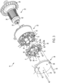
FIG. 5 is a perspective view illustrating a stator assembly of the electric motor ofFIG. 2 . -
FIG. 6 is a partially exploded perspective view illustrating the stator assembly ofFIG. 5 . -
FIG. 7 is a partially exploded perspective view illustrating the stator assembly ofFIG. 5 with portions removed. -
FIGS. 8 and 9 are perspective views illustrating portions of the stator assembly ofFIG. 5 . -
FIG. 10 is a perspective view illustrating a bus bar assembly of the electric motor ofFIG. 2 . -
FIG. 11 is an exploded perspective view illustrating the bus bar assembly ofFIG. 10 . -
FIG. 12 is a perspective cross-sectional view of the electric motor ofFIG. 2 , taken along lines 12-12 ofFIG. 2 . -
FIG. 13 is a perspective view of a stator assembly according to another embodiment. -
FIG. 14 is an exploded perspective view of the stator assembly ofFIG. 13 . -
FIGS. 15 and 16 are perspective views of portions of the stator assembly ofFIG. 13 . -
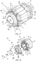
FIG. 17 is a perspective view of portions of an electric motor according to another embodiment. -
FIG. 18 is a partially exploded perspective view of the electric motor ofFIG. 17 . -
FIG. 19 is a side view illustrating a bus bar assembly of the electric motor ofFIG. 17 . -
FIG. 20 is a plan view of the bus bar assembly ofFIG. 19 . -
FIG. 21 is an exploded perspective view of the bus bar assembly ofFIG. 19 . -
FIG. 22 is an exploded plan view of the bus bar assembly ofFIG. 19 with portions removed. -
FIGS. 23-25 illustrate portions of an electric motor according to another embodiment where a bus bar assembly is secured to a stator assembly by an ultrasonic welding method. -
FIGS. 26-31 illustrate portions of an electric motor according to another embodiment where a bus bar assembly is secured to a stator assembly by a thermal press method. -
FIG. 32 illustrates portions of an electric motor according to another embodiment where a bus bar assembly is secured to a stator assembly by a heat staking method. -
FIG. 33 is a partial perspective view of an electric motor according to another embodiment where a circuit board assembly is secured to a bus bar assembly by a heat staking method. -
FIG. 34 is a side view of a bus bar assembly according to another embodiment. -
FIG. 35 is a partial perspective view of the bus bar assembly ofFIG. 34 . -
FIG. 36 is a top view of a circuit board assembly that can be coupled to the bus bar assembly ofFIG. 35 by a heat staking method. -
FIG. 37 is a partial perspective view illustrating the circuit board assembly ofFIG. 36 secured to the bus bar assembly ofFIG. 34 by heat staking. - Before any embodiments of the disclosure are explained in detail, it is to be understood that the disclosure is not limited in its application to the details of construction and the arrangement of components set forth in the following description or illustrated in the following drawings. The disclosure is capable of other embodiments and of being practiced or of being carried out in various ways. Also, it is to be understood that the phraseology and terminology used herein is for the purpose of description and should not be regarded as limiting.
-
FIG. 1 and 2 illustrate apower tool 10 such as, e.g., a drill, a rotary impact tool, and the like. Thepower tool 10 includes ahousing 12 and anelectric motor 14. Thepower tool 10 is operable with abattery pack 16 removably coupled to abattery receptacle 18 located at a bottom end of thehousing 12. Thebattery pack 16 includes a plurality of battery cells (not shown), which are electrically connected to provide the desired output (e.g., nominal voltage, current capacity, etc.) of thebattery pack 16. Theelectric motor 14 receives power from thebattery pack 16 when thebattery pack 16 is coupled to thebattery receptacle 18. - In some embodiments, the
power tool 10 may include a power cord for electrically connecting themotor 14 to a source of AC power. Thebattery pack 16 is the preferred means for powering thepower tool 10, however, because a cordless power tool can be used in locations where other power sources are unavailable. - With reference to
FIGS. 2-4 , the illustratedmotor 14 is a brushless direct current ("BLDC") motor with astator assembly 20 and arotor assembly 22 that is rotatable with respect to thestator assembly 20 about anaxis 24. Therotor assembly 22 includes arotor body 26 and afan 28 that are each supported on arotor shaft 30. Thefan 28 is located adjacent a first end orfront end 32 of themotor 14. Thestator assembly 20 includes acentral cavity 34 that receives therotor assembly 22 for rotation about theaxis 24. Themotor 14 also includes abus bar assembly 36 and a printed circuit board assembly (PCBA) 38 that are each coupled to thestator assembly 20 at a second end orrear end 40 of themotor 14 opposite thefront end 32. - With reference to
FIGS. 5-9 , thestator assembly 20 is asegmented stator assembly 20 including, in the illustrated embodiment, sixstator segments 42 arranged within atubular housing 44. Eachstator segment 42 includes a core 46, a moldedinsulator 48, and a stator winding 50.Adjacent stator segments 42 are interconnected to each other with a notch andprotrusion interlock 52. Specifically, eachstator segment 42 includes alongitudinally extending notch 54 provided in a firstcircumferential end face 56, and alongitudinally extending protrusion 58 protruding from a secondcircumferential end face 60. Thenotch 54 of onestator segment 42 receives theprotrusion 58 of theadjacent stator segment 42 to align twoadjacent stator segments 42. - The
tubular housing 44 surrounds the arrangedstator segments 42 to fix thestator segments 42 together. Specifically, thetubular housing 44 includes atubular wall 62 that defines aninner cavity 64, and thestator segments 42 are received into theinner cavity 64 such that thetubular wall 62 converges about thestator segments 42. In one example, thetubular housing 44 can be heated to expand an outside diameter of thetubular wall 62, and then thetubular housing 44 can be pressed onto thestator segments 42. As thetubular housing 44 cools, thetubular wall 62 contracts about thestator segments 42 to secure the assembly. In the illustrated embodiment, thetubular housing 44 also includes mountingtabs 66 extending radially outward from thetubular wall 62, with each mountingtab 66 defining a mountingaperture 68 configured to receive a fastener (e.g., a screw) for securing themotor 14 to, e.g., a gearcase (not shown). - With reference to
FIG. 8 , each moldedinsulator 48 includes a mountingportion 70 protruding toward therear end 40 of themotor 14. Each mountingportion 70 defines an axially extending threaded bore 72 that receives afirst fastener 74 or asecond fastener 76 to secure thebus bar assembly 36 and thePCBA 38 to the stator assembly 20 (FIGS. 3 and4 ). - With reference to
FIGS. 10 and 11 , thebus bar assembly 36 includes threeannular conductors 78 generally extending circumferentially about themotor 14, and anon-conductive body 80 that fixedly supports theconductors 78. Eachconductor 78 includes twotangs 82 provided at opposite ends of theconductor 78, and a terminal 84 extending in the axial direction of themotor 14. Each terminal 84 mechanically and electrically connects to thePCBA 38. Specifically, thePCBA 38 includes a plurality of apertures 85 (FIGS. 3 and12 ) corresponding to the locations of theterminals 84. During assembly, theterminals 84 are inserted into the apertures 85 and soldered to thePCBA 38 to mechanically and electrically connect theterminals 84 to thePCBA 38. Each stator winding 50 includes a pair of leads 86 (FIG. 8 ) that connect to theadjacent tangs 82 of theconductors 78. The leads 86 can be soldered or fused to thetangs 82. In this way, theconductors 78 electrically connect thestator windings 50 to thePCBA 38. ThePCBA 38 receives power from thebattery pack 16 and selectively applies electrical current to thewindings 50 to thereby cause therotor shaft 30 to rotate about theaxis 24. - The
non-conductive body 80 includes acentral hub 88 that defines a central aperture or bearingpocket 90 that receives and supports a rotor bearing 92 (FIGS. 10-12 ). Therotor bearing 92 receives therotor shaft 30 to rotatably support therotor assembly 22. Thenon-conductive body 80 further includes radial arms 94 that extend radially outward from thecentral hub 88. In some embodiments, the number of radial arms 94 corresponds to the number of mountingportions 70 of thestator assembly 20. In the illustrated embodiment, the non-conductive body includes six radial arms 94 that correspond to the six mountingportions 70 of the sixstator segments 42. Each radial arm 94 defines afirst aperture 96 that aligns with the threaded bore 72 of the corresponding mountingportion 70. - With reference to
FIGS. 3 and12 , thebus bar assembly 36 is secured to the mountingportions 70 of thestator assembly 20 by thefirst fasteners 74 and thesecond fasteners 76, and thePCBA 38 is secured to thestator assembly 20 by thesecond fasteners 76. ThePCBA 38 includessecond apertures 98 extending through thePCBA 38 and corresponding to thefirst apertures 96 of every other radial arm 94 in the circumferential direction. Thus, the radial arms 94 include first radial arms 94a and second radial arms 94b. The first radial arms 94a are coupled directly to the mountingportions 70 by thefirst fasteners 74. The second radial arms 94b are coupled to both the mountingportions 70 and thePCBA 38 by thesecond fasteners 76. More specifically, thefirst fasteners 74 are received through thefirst apertures 96 of the first radial arms 94a and tighten into the threaded bores 72 to secure the first radial arms 94a to the mountingportions 70. Thesecond fasteners 76 are received through thesecond apertures 98 of thePCBA 38 and through thefirst apertures 96 of the second radial arms 94b, and tighten into the threaded bores to secure both thePCBA 38 and the second radial arms 94 to the mountingportions 70. As such, thebus bar assembly 36 is secured to each mountingportion 70 of eachstator segment 42, and supports the rotor bearing 92 to center therotor assembly 22 with respect to thestator assembly 20. - With reference to
FIGS. 3 ,4 , and12 , thePCBA 38 includes a printed circuit board (PCB) 95 and a heat sink 97 secured to the PCB 95. The heat sink 97 includes a plurality of recesses 97a, and thenon-conductive body 80 includes a plurality of axially extending protrusions 80a that are received within the corresponding recesses 97a to align thePCBA 38 with thebus bar assembly 36. -
FIGS. 13-16 illustrate astator assembly 120 according to another embodiment of the disclosure. Thestator assembly 120 is similar to thestator assembly 20 described above and includes much of the same structure as thestator assembly 20. And, thestator assembly 120 is operable with each therotor assembly 22, thebus bar assembly 36, and thePCBA 38 described above. Features and elements of thestator assembly 120 that are similar to the features and elements of thestator assembly 20 are assigned the same reference numerals "plus 100." It should be understood that the features of thestator assembly 120 that are not explicitly described below have the same properties as the features of thestator assembly 20. - With reference to
FIGS. 13 and14 , thestator assembly 120 couples to thebus bar assembly 36 and thePCBA 38 via thefirst fasteners 74 and thesecond fasteners 76 in the same manner as described above in connection with thestator assembly 20. And, thestator assembly 120 similarly includesstator segments 142 arranged end to end. However, thestator assembly 120 does not include a tubular housing. Instead, thestator segments 142 are laser welded at notch andprotrusion interlocks 152 to secure thestator segments 142 together. Moreover, thestator segments 142 are not uniform, but instead includefirst stator segments 142a andsecond stator segments 142b arranged in an alternating order (FIGS. 15 and 16 ). More specifically, eachfirst stator segment 142a is connected to asecond stator segment 142b at each circumferential end. Thefirst stator segments 142a each include a mountingrib 121 protruding radially outward and extending lengthwise in the axial direction. Each mountingrib 121 defines a mountingaperture 123 that receives a fastener for mounting thestator assembly 120 to, e.g., a gearcase (not shown). Thesecond stator segments 142b do not include mounting ribs, but do include axially extending grooves that receive a portion of the moldedinsulator 148. -
FIGS. 17-22 illustrate all or portions of anelectric motor 1014 according to another embodiment of the disclosure. Themotor 1014 includes the segmentedstator assembly 120 described herein in connection withFIGS. 13-16 , and is operable with therotor assembly 22 described herein in connection withFIGS. 2-4 and12 . - The
motor 1014 includes abus bar assembly 1036 that couples to an axial end of thestator assembly 120. Thebus bar assembly 1036 includes three annular conductors 1078 (FIGS. 21-22 ) and anon-conductive body 1080 that fixedly supports theconductors 1078. Eachconductor 1078 includes four winding connection terminals ortangs 1082 provided at two opposite ends of theconductor 1078, and apower connection terminal 1084 protruding from theconductor 1078. Thenon-conductive body 1080 includes three mountingarms 1094 protruding radially from a central region of thenon-conductive body 1080 and spaced at equal intervals about the circumference thereof. The mountingarms 1094 engage mountingportions 170 defined by the moldedinsulators 148 of thefirst stator segments 142a. The mountingarms 1094 can be secured to the mountingportions 170 via, e.g., threaded fasteners. - Each terminal 1084 electrically connects to a PCBA (e.g., via wires; not shown) that receives power from the battery pack 16 (
FIG. 1 ) and selectively applies electrical current to thestator windings 150. The leads 186 of thewindings 150 connect to the twoadjacent tangs 1082 of theconductors 1078. In this way, theconductors 1078 electrically connect thestator windings 150 to the PCBA. - The
non-conductive body 1080 defines a central aperture or bearingpocket 1090 that receives the rotor bearing 92 (FIG. 3 ). Therotor bearing 92 receives therotor shaft 30 of the rotor assembly 22 (FIG. 3 ) to rotatably support therotor assembly 22. Since thebus bar assembly 1036 is secured to each mountingportion 170 of eachstator segment 142a, and further supports the rotor bearing 92, thebus bar assembly 1036 centers therotor assembly 22 with respect to thestator assembly 120. - A printed circuit board assembly (PCBA) 1039, such as a rotor position sensor circuit board, is coupled to the
non-conductive body 1080 of thebus bar assembly 1036. ThePCBA 1039 is generally annular in shape and received into a corresponding centrally located, annularly shapedrecess 1041 defined in thenon-conductive body 1080 and secured thereto by threaded fasteners. ThePCBA 1039 covers at least a portion of thebearing pocket 1090. - As shown in
FIG. 19 , thenon-conductive body 1080 includes a firstaxial surface 1023 extending at a first axial end thereof and a secondaxial surface 1025 extending at a second axial end thereof. The firstaxial surface 1023 faces toward thestator assembly 120 and the secondaxial surface 1025 faces away from thestator assembly 120. Thenon-conductive body 1080 also includes a circumferentialouter surface 1043 that extends between the first and secondaxial surfaces tangs 1082 each protrude from the circumferentialouter surface 1043 generally in the radial direction. Eachtang 1082 includes a forkedtip 1045 at its distal end and is generally planar in shape. The corresponding lead 186 (FIG. 17 ) of the adjacent stator winding 150 is received by and contacts the forkedtip 1045 and is mechanically attached thereto by, e.g., laser welding. In other embodiments, theleads 186 can be attached to the forkedtips 1045 by other means, such as soldering, ultrasonic welding, crimping, and the like. As further shown inFIG. 19 , each of thetangs 1082 are also generally located within the same axial region of themotor 1014. In particular, eachtang 1082 lies within and defines afirst plane 1031 that extends perpendicular to thecentral axis 1024. As shown inFIG. 20 , thetangs 1082 are spaced at generally equal intervals about the circumference of thenon-conductive body 1080. As such, an angle A is measured on center about thecentral axis 1024 between any twoadjacent tangs 1082. In the illustrated embodiment, thebus bar assembly 1036 includes twelvetangs 1082 and the angle A is approximately 30 degrees. - In the illustrated embodiment, the
bus bar assembly 1036 includes threepower connection terminals 1084 that protrude from the secondaxial surface 1025 of thenon-conductive body 1080 in anaxial direction 1037. Each terminal 1084 is formed as a straight leg oriented perpendicular to thecentral axis 1024. All of theterminals 1084 extend generally parallel to one another and perpendicular to thefirst plane 1031. - The
bus bar assembly 1036 is configured to provide a parallel delta winding configuration for themotor 1014. Specifically, when theleads 186 of thewindings 150 forming each coil are connected to the corresponding forkedtips 1045 of the respectivenearest tangs 1082, thewindings 150 are arranged in a parallel delta winding configuration. - In the embodiments of
FIGS. 1-22 described herein, thebus bar assemblies stator assemblies FIGS. 23-32 illustrate alternative embodiments of electric motors that are similar to theelectric motor 1014 described herein, but which utilize alternative means of securing the bus bar assembly to the stator assembly. The alternative means described in connections withFIGS. 23-32 do not use threaded fasteners. -
FIGS. 23-25 illustrate portions of anelectric motor 1014a according to another embodiment of the disclosure. Themotor 1014a includes asegmented stator assembly 120a similar to thesegmented stator assembly 120 described herein in connection withFIGS. 13-16 . Themotor 1014a also includes abus bar assembly 1036a similar to thebus bar assembly 1036 described herein in connection withFIGS. 17-22 . Thebus bar assembly 1036a may be secured to thestator assembly 120a by an ultrasonic welding process as will be described herein. Theelectric motor 1014a is operable with and may include therotor assembly 22 described herein in connection withFIGS. 2-4 and12 . - The
stator assembly 120a is asegmented stator assembly 120a including, in the illustrated embodiment, six stator segments 143a secured to one another at their circumferential ends. Each stator segment 143a includes acore 146a, a moldedinsulator 148a affixed to thecore 146a (e.g., formed of resin via injection molding), and a stator winding 150a. In other embodiments (not shown), the stator assembly may not be segmented, but instead may include a unitary annular core and a unitary insulator, while still utilizing the ultrasonic welding process to attach thebus bar assembly 1036a as described herein. - In the illustrated embodiment, the
bus bar assembly 1036a includes a plurality ofconductors 1078a with radially protruding winding connection terminals ortangs 1082a. Each stator winding 150a includes a pair ofleads 186a that connect to theadjacent tangs 1082a. Thebus bar assembly 1036a also includes anon-conductive body 1080a (e.g., formed of resin) that fixedly supports theconductors 1078a. APCBA 1039a, such as a rotor position sensor circuit board, is coupled to thenon-conductive body 1080a. Thenon-conductive body 1080a further defines a central aperture or bearing pocket (e.g., such as bearingpocket 1090a,FIG. 25 ) that receives a rotor bearing 92 (FIGS. 10-12 ). -
FIG. 24 shows a portion of thebus bar assembly 1036a secured to thestator assembly 120a by ultrasonic welding. Specifically, the moldedinsulator 148a may be formed from a first thermoplastic material and thenon-conductive body 1080a may also be formed of a second thermoplastic material. The first and second thermoplastic materials may be the same or different. Each of the first and second thermoplastic materials may experience melting when heated above their respective melt temperatures and may bond to one another when cooled. During the ultrasonic welding process, the parts are vibrated at high frequencies to generate heat that locally melts and fuses the parts together at the contactingsurfaces inboard surface 1075a of thenon-conductive body 26 contacts an axiallyouter surface 175a of acoil protector portion 174a of the moldedinsulator 148a. -
FIG. 25 shows a second example of ultrasonic welding where the ultrasonic welds are formed at different locations. Specifically, the welds are formed where an outercircumferential surface 1079a of thebearing pocket 1090a contacts an innerannular surface 179a of thecoil protection portions 174a. -
FIGS. 26-28 illustrate portions of anelectric motor 1014b according to another embodiment of the disclosure. Theelectric motor 1014b is similar in many respects to theelectric motor 1014a described herein in connection withFIGS. 23-25 , and as such, the following description will focus on the differences between themotors bus bar assembly 1036b is secured to astator assembly 120b via a thermal press method. A moldedinsulator 148b of thestator assembly 120b includes a plurality of elongated, axially protrudingposts 170b. Anon-conductive body 1080b of thebus bar assembly 1036b includes a plurality of radially protruding tabs orradial arms 1094b that each define receptacles configured as slot-shapedapertures 1095b shaped and sized to closely receive theposts 170b. At least theposts 170b may be formed from a first thermoplastic material and the receptacles orapertures 1095b may be defined by a second thermoplastic material. The first and second thermoplastic materials may be the same or different. Each of the first and second thermoplastic materials may experience melting when heated above their respective melt temperatures and may bond to one another when cooled. In the illustrated embodiment, theinsulator 148b is formed entirely of the first thermoplastic material and thenon-conductive body 1080b is formed entirely of the second thermoplastic material. - First, the
posts 170b are each heated by a thermal tip 1100 (FIG. 27 ). Once theposts 170b reach a predetermined temperature, thethermal tips 1100 are removed and thebus bar assembly 1036b is quickly pressed onto thestator assembly 120b so that the slot-shapedapertures 1095b receive theposts 170b by press fit. Theheated posts 170b bond to the surface of the slot-shapedapertures 1095b to form a secure connection. Therefore, the connections formed between theposts 170b and the surface of thenon-conductive body 1080b defining the slot-shapedapertures 1095b secure thenon-conductive body 1080b to the moldedinsulator 148b. In the illustrated embodiment, theposts 170b extend entirely through theapertures 1095b from a first axially facing surface of thenon-conductive body 1080b to an opposite, second axially facing surface of thenon-conductive body 1080b. In some embodiments, distal ends of theposts 170b protrude beyond theaperture 1095b and beyond the second axially facing surface. - In other embodiments of the
electric motor 1014b, theinsulator 148b may instead define the receptacles, or slot-shaped apertures, and thenon-conductive body 1080b may correspondingly include the posts. The same is generally true for the following description of theelectric motors -
FIGS. 29-31 illustrate portions of anelectric motor 1014c according to another embodiment of the disclosure. Theelectric motor 1014c is similar in many respects to theelectric motor 1014b described herein in connection withFIGS. 26-28 , and as such, the following description will focus on the differences between themotors bus bar assembly 1036c is secured to astator assembly 120c via a thermal press method, but the shapes of the posts and radial arms differ from those shown inFIGS. 26-28 . A moldedinsulator 148c of thestator assembly 120c includes axially protrudingcylindrical posts 170c, and anon-conductive body 1080c of thebus bar assembly 1036c includesradial arms 1094c that each define receptacles configured ascylindrical recesses 1095c that extend only partially through theradial arms 1094c in the axial direction. Thecylindrical posts 170c are thermally pressed into therecesses 1095c in a manner similar to that described herein in connection withFIGS. 26-28 . However, theradial arms 1094c also includerelief apertures 1096c that communicate with therecesses 1095c on an axially outer side of theradial arms 1094c. Therelief apertures 1096c provide a relief area for material displacement of theposts 170c during the thermal press process. Therelief aperture 1096c has a smaller diameter than that of therecess 1095c, and a shoulder is defined between therecess 1095c and therelief aperture 1096c. -
FIG. 32 illustrates a heat staking method for securing anon-conductive body 1080d of a bus bar assembly (not shown) to a moldedinsulator 148d of a stator assembly (not shown). Any of thebus bar assemblies stator assemblies FIGS. 26-31 . During the heat staking method, an axially protruding stake or post 170d of theinsulator 148d is pressed into anaperture 1095d of thenon-conductive body 1080d before any heating step. Thepost 170d is formed having an axial length greater than an axial length of theaperture 1095d, so that an end portion of thepost 170d protrudes beyond a rim of theaperture 1095d. The end portion of thepost 170d is heated until partially melted to form a dome or flange over the rim of theaperture 1095d. This provides a secure mechanical connection between theinsulator 148d and thenon-conductive body 1080a. -
FIG. 33 illustrates portions of anelectric motor 1014e according to another embodiment of the disclosure. Theelectric motor 1014e includes aPCBA 1039e that is secured to anon-conductive body 1080e of abus bar assembly 1036e by a heat staking method. Theelectric motor 1014e is similar in many respects to theelectric motor 1014c described herein in connection withFIGS. 29-31 , and as such, the following description will focus on the differences between themotors - In this embodiment, the
bus bar assembly 1036e is secured to astator assembly 120e via the thermal press method described herein in connection withFIGS. 29-31 . ThePCBA 1039e (e.g., a position sensor circuit board) is generally annular in shape and received into a corresponding centrally located, annularly shapedrecess 1041e defined in thenon-conductive body 1080e. ThePCBA 1039e covers at least a portion of a bearing pocket (not shown, but seeFIG. 25 illustrating asimilar bearing pocket 1090a). ThePCBA 1039e includes three mountingarms 1085e protruding radially outward from an otherwise circularperipheral edge 1087e of thePCBA 1039e. The mountingarms 1085e are angularly spaced equidistantly from one another and each define a mountingaperture 1086e. Thenon-conductive body 1080e includes three mountingposts 1088e protruding axially away from an outer surface thereof. - During the heat staking method, the
PCBA 1039e is inserted into therecess 1041e prior to any heating step. The mountingposts 1088e are received into the corresponding mountingapertures 1086e. The mountingposts 1088e have an axial length greater than an axial length of the mountingapertures 1086e, so that an end portion of thepost 1088e protrudes beyond a rim of the respective mountingaperture 1086e. The end portion of thepost 1088e is heated until partially melted to form a dome or rivet over the rim of theaperture 1086e and over a portion of the surface of thePCBA 1039e. This provides a secure mechanical connection between theinsulator PCBA 1039e and thenon-conductive body 1080e. - Securing the
PCBA 1039e to thebus bar assembly 1036e by heat staking the mountingposts 1088e provides advantages over using threaded fasteners. For example, because there are conductors extending within thenon-conductive body 1080e, any threaded bore provided in the non-conductive body can interfere with the conductors. Eliminating the threaded fasteners and instead using heat staked mountingposts 1088e avoids this issue and allows the posts to be more freely located as necessary to accommodate thePCBA 1039e. This provides size advantages over prior art electric motors, such as allowing the PCBA to be miniaturized without adding material to the non-conductive body to accommodate threaded bores of sufficient depth which would otherwise increase an overall axial length of the motor assembly. -
FIGS. 34-37 illustrate abus bar assembly 1036f and aPCBA 1039f according to another embodiment. Thebus bar assembly 1036f and thePCBA 1039f are similar in many respects to thebus bar assembly 1036e and thePCBA 1039e described herein in connection withFIG. 33 , and the following description will focus on some differences between them. - In this embodiment, the
PCBA 1039f is secured to anon-conductive body 1080f of thebus bar assembly 1036f by a heat staking method. ThePCBA 1039f (e.g., a position sensor circuit board) is generally annular in shape and received into a corresponding centrally located, annularly shapedrecess 1041f defined in thenon-conductive body 1080f. ThePCBA 1039f covers at least a portion of abearing pocket 1090f defined in a central region of thenon-conductive body 1080f. ThePCBA 1039f includes a circularperipheral edge 1087f and defines three mountingapertures 1086f that are each positioned adjacent the circularperipheral edge 1087f and angularly spaced from one another at equal intervals. ThePCBA 1039f also defines a locatingnotch 1089f that interrupts the circularperipheral edge 1087f. Thenon-conductive body 1080f includes acorresponding locating protrusion 1091f that interrupts a circularperipheral edge 1092f of therecess 1041f and protrudes into therecess 1041f. The locatingnotch 1089f receives the locatingprotrusion 1091f to properly orient thePCBA 1039f relative to thebus bar assembly 1036f during assembly. In other embodiments (not shown), the protrusion may instead be provided on thePCBA 1039f and thenon-conductive body 1080f may define the corresponding notch. - The
non-conductive body 1080f includes three mountingposts 1088f protruding axially away from a bottom surface of therecess 1041f. As shown inFIG. 34 , the mountingposts 1088f protrude beyond anaxial end face 1093f of thenon-conductive body 1080f. In other words, theaxial end face 1093f of thenon-conductive body 1080f defines aflat plane 1097f, and the mountingposts 1088f protrude beyond theflat plane 1097f. - During the heat staking method, the PCBA 1039fis inserted into the
recess 1041f prior to any heating step. The mountingposts 1088f are received into the corresponding mountingapertures 1086f, and the locatingprotrusion 1091f is received into the locatingnotch 1089f to orient thePCBA 1039f. The mountingposts 1088f have an axial length greater than an axial length of the mountingapertures 1086f, so that an end portion of thepost 1088f protrudes beyond a rim of therespective mounting aperture 1086f. The end portion of thepost 1088f is heated until partially melted to form a dome or rivet 1098f over the rim of the mountingaperture 1086f and over a portion of the surface of thePCBA 1039f. This provides a secure mechanical connection between theinsulator PCBA 1039f and thenon-conductive body 1080f. - Although the disclosure has been described in detail with reference to certain preferred embodiments, variations and modifications exist within the scope and spirit of one or more independent aspects of the disclosure as described. When used in this specification and claims, the terms "comprises" and "comprising" and variations thereof mean that the specified features, steps or integers are included. The terms are not to be interpreted to exclude the presence of other features, steps or components.
- Representative features are set out in the following clauses, which stand alone or may be combined, in any combination, with one or more features disclosed in the text and/or drawings of the specification.
- 1. An electric motor comprising:
- a rotor assembly including a rotor shaft defining a rotational axis;
- a stator assembly including a core, an insulator at least partially covering the core, and a plurality of windings, the insulator defining one of a post that protrudes in an axial direction parallel with the rotational axis or a receptacle in which the post is receivable; and
- a bus bar assembly including a non-conductive body and a plurality of conductors configured to make an electrical connection between at least two windings of the plurality of windings, the non-conductive body including the other of the post or the receptacle;
- wherein the receptacle includes at least one of an aperture or a recess, and
- wherein the post is received within the receptacle to secure the non-conductive body to the insulator.
- 2. The electric motor of clause 1, wherein the non-conductive body includes a radially protruding arm, and wherein the one of the post or the receptacle is defined by the radially protruding arm.
- 3. The electric motor of clause 1, wherein the receptacle comprises an aperture and is defined by the non-conductive body, and wherein the post extends entirely through the aperture between a first axially facing surface of the non-conductive body and an opposite, second axially facing surface of the non-conductive body.
- 4. The electric motor of clause 1, wherein the post is cylindrical.
- 5. The electric motor of clause 1, wherein the receptacle is defined by the non-conductive body and comprises a recess that extends only partially through the non-conductive body in an axial direction.
- 6. The electric motor of clause 5, wherein the non-conductive body further defines a relief aperture that communicates with the recess, and wherein a shoulder is defined between the recess and the relief aperture.
- 7. The electric motor of clause 1, further comprising a printed circuit board assembly (PCBA) defining a mounting aperture, and wherein the non-conductive body further defines a mounting post that is received by the mounting aperture to secure the PCBA to the non-conductive body.
- 8. The electric motor of clause 1, further comprising a rotor bearing that rotatably supports the rotor shaft, wherein the non-conductive body further defines a bearing pocket that receives and supports the rotor bearing.
- 9. The electric motor of clause 1, wherein the core is a first core and the insulator is a first insulator, and wherein the stator assembly comprises a plurality of stator segments including a first stator segment and a second stator segment positioned adjacent the first stator segment in a circumferential direction, and wherein the first stator segment includes the first core, the first insulator, and a first winding of the plurality of windings, and wherein the second stator segment includes a second core, a second insulator, and a second winding of the plurality of windings.
- 10. The electric motor of clause 9, wherein the receptacle is a first receptacle of a plurality of receptacles defined by the non-conductive body, and wherein the post is a first post defined by the first insulator, and wherein the second insulator defines a second post that is received by a second receptacle of the plurality of receptacles to secure the non-conductive body to the second insulator.
- 11. The electric motor of
clause 10, wherein the post and the receptacle are made from a thermoplastic material that melts in response to being heated above a melt temperature and bonds in response to being subsequently cooled below the melt temperature to affix the non-conductive body to the insulator. - 12. An electric motor comprising:
- a rotor assembly including a rotor shaft;
- a stator assembly including a core, an insulator at least partially covering the core, and a plurality of windings;
- a bus bar assembly including a non-conductive body and a plurality of conductors configured to make an electrical connection between at least two windings of the plurality of windings, the non-conductive body defining a mounting post; and
- a printed circuit board assembly (PCBA) defining a mounting aperture that receives the mounting post to secure the PCBA to the non-conductive body.
- 13. The electric motor of
clause 12, wherein the non-conductive body defines an annular recess that receives the PCBA. - 14. The electric motor of clause 13, wherein the PCBA includes a circular peripheral edge and a mounting arm that protrudes radially from the circular peripheral edge, and wherein the mounting arm defines the mounting aperture.
- 15. The electric motor of clause 13, wherein the non-conductive body further defines a locating protrusion that protrudes into the annular recess, and wherein the PCBA includes a circular peripheral edge and a locating notch that interrupts the circular peripheral edge, and wherein the locating notch receives the locating protrusion.
- 16. The electric motor of
clause 12, wherein the insulator defines an insulator post that protrudes axially away from the core, and wherein the non-conductive body defines a receptacle that receives the insulator post to secure the non-conductive body to the insulator, the receptacle comprising at least one of an aperture or a recess. - 17. The electric motor of
clause 12, wherein the core is a first core and the insulator is a first insulator, and wherein the stator assembly comprises a plurality of stator segments including a first stator segment and a second stator segment positioned adjacent the first stator segment in a circumferential direction, and wherein the first stator segment includes the first core, the first insulator, and a first winding of the plurality of windings, and wherein the second stator segment includes a second core, a second insulator, and a second winding of the plurality of windings. - 18. A method of assembling an electric motor, the method comprising:
- providing a rotor assembly including a rotor shaft;
- providing a stator assembly including a core, an insulator at least partially covering the core, and a plurality of windings;
- providing a bus bar assembly including a non-conductive body and a plurality of conductors;
- ultrasonically welding the non-conductive body to the insulator; and
- making an electrical connection between at least two windings of the plurality of windings and the plurality of conductors.
- 19. The method of
clause 18, wherein the non-conductive body includes an inboard surface facing toward the insulator, and wherein the insulator includes a coil protector portion having an axially outer surface, and wherein ultrasonically welding the non-conductive body to the insulator produces an ultrasonic weld located where the inboard surface contacts the axially outer surface. - 20. The method of
clause 18, further comprising inserting a bearing within a bearing pocket of the non-conductive body, wherein the bearing pocket defines an outer circumferential surface, and wherein the insulator includes a coil protector portion having an inner annular surface, and wherein ultrasonically welding the non-conductive body to the insulator produces an ultrasonic weld located where the outer circumferential surface contacts the inner annular surface.
Claims (15)
- An electric motor comprising:a rotor assembly including a rotor shaft defining a rotational axis;a stator assembly including a core, an insulator at least partially covering the core, and a plurality of windings, the insulator defining one of a post that protrudes in an axial direction parallel with the rotational axis or a receptacle in which the post is receivable; anda bus bar assembly including a non-conductive body and a plurality of conductors configured to make an electrical connection between at least two windings of the plurality of windings, the non-conductive body including the other of the post or the receptacle;wherein the receptacle includes at least one of an aperture or a recess, andwherein the post is received within the receptacle to secure the non-conductive body to the insulator.
- The electric motor of claim 1, wherein the non-conductive body includes a radially protruding arm, and wherein the one of the post or the receptacle is defined by the radially protruding arm.
- The electric motor of claim 1 or 2, wherein the receptacle comprises an aperture and is defined by the non-conductive body, and wherein the post extends entirely through the aperture between a first axially facing surface of the non-conductive body and an opposite, second axially facing surface of the non-conductive body.
- The electric motor of any preceding claim, wherein the post is cylindrical, and/or
wherein the receptacle is defined by the non-conductive body and comprises a recess that extends only partially through the non-conductive body in an axial direction, preferably wherein the non-conductive body further defines a relief aperture that communicates with the recess, and wherein a shoulder is defined between the recess and the relief aperture. - The electric motor of any preceding claim, further comprising a printed circuit board assembly (PCBA) defining a mounting aperture, and wherein the non-conductive body further defines a mounting post that is received by the mounting aperture to secure the PCBA to the non-conductive body, and/or
further comprising a rotor bearing that rotatably supports the rotor shaft, wherein the non-conductive body further defines a bearing pocket that receives and supports the rotor bearing. - The electric motor of any preceding claim, wherein the core is a first core and the insulator is a first insulator, and wherein the stator assembly comprises a plurality of stator segments including a first stator segment and a second stator segment positioned adjacent the first stator segment in a circumferential direction, and wherein the first stator segment includes the first core, the first insulator, and a first winding of the plurality of windings, and wherein the second stator segment includes a second core, a second insulator, and a second winding of the plurality of windings.
- The electric motor of claim 6, wherein the receptacle is a first receptacle of a plurality of receptacles defined by the non-conductive body, and wherein the post is a first post defined by the first insulator, and wherein the second insulator defines a second post that is received by a second receptacle of the plurality of receptacles to secure the non-conductive body to the second insulator.
- The electric motor of claim 7, wherein the post and the receptacle are made from a thermoplastic material that melts in response to being heated above a melt temperature and bonds in response to being subsequently cooled below the melt temperature to affix the non-conductive body to the insulator.
- An electric motor comprising:a rotor assembly including a rotor shaft;a stator assembly including a core, an insulator at least partially covering the core, and a plurality of windings;a bus bar assembly including a non-conductive body and a plurality of conductors configured to make an electrical connection between at least two windings of the plurality of windings, the non-conductive body defining a mounting post; anda printed circuit board assembly (PCBA) defining a mounting aperture that receives the mounting post to secure the PCBA to the non-conductive body.
- The electric motor of claim 9, wherein the non-conductive body defines an annular recess that receives the PCBA, preferably wherein the PCBA includes a circular peripheral edge and a mounting arm that protrudes radially from the circular peripheral edge, and wherein the mounting arm defines the mounting aperture.
- The electric motor of claim 10, wherein the non-conductive body further defines a locating protrusion that protrudes into the annular recess, and wherein the PCBA includes a circular peripheral edge and a locating notch that interrupts the circular peripheral edge, and wherein the locating notch receives the locating protrusion.
- The electric motor of any one of claims 9 to 11, wherein the insulator defines an insulator post that protrudes axially away from the core, and wherein the non-conductive body defines a receptacle that receives the insulator post to secure the non-conductive body to the insulator, the receptacle comprising at least one of an aperture or a recess.
- The electric motor of any one of claims 9 to 12, wherein the core is a first core and the insulator is a first insulator, and wherein the stator assembly comprises a plurality of stator segments including a first stator segment and a second stator segment positioned adjacent the first stator segment in a circumferential direction, and wherein the first stator segment includes the first core, the first insulator, and a first winding of the plurality of windings, and wherein the second stator segment includes a second core, a second insulator, and a second winding of the plurality of windings.
- A method of assembling an electric motor, the method comprising:providing a rotor assembly including a rotor shaft;providing a stator assembly including a core, an insulator at least partially covering the core, and a plurality of windings;providing a bus bar assembly including a non-conductive body and a plurality of conductors;ultrasonically welding the non-conductive body to the insulator; andmaking an electrical connection between at least two windings of the plurality of windings and the plurality of conductors.
- The method of claim 18, wherein the non-conductive body includes an inboard surface facing toward the insulator, and wherein the insulator includes a coil protector portion having an axially outer surface, and wherein ultrasonically welding the non-conductive body to the insulator produces an ultrasonic weld located where the inboard surface contacts the axially outer surface, and/or
further comprising inserting a bearing within a bearing pocket of the non-conductive body, wherein the bearing pocket defines an outer circumferential surface, and wherein the insulator includes a coil protector portion having an inner annular surface, and wherein ultrasonically welding the non-conductive body to the insulator produces an ultrasonic weld located where the outer circumferential surface contacts the inner annular surface.
Applications Claiming Priority (2)
| Application Number | Priority Date | Filing Date | Title |
|---|---|---|---|
| US202263387619P | 2022-12-15 | 2022-12-15 | |
| US202263387882P | 2022-12-16 | 2022-12-16 |
Publications (1)
| Publication Number | Publication Date |
|---|---|
| EP4391310A1 true EP4391310A1 (en) | 2024-06-26 |
Family
ID=89222495
Family Applications (1)
| Application Number | Title | Priority Date | Filing Date |
|---|---|---|---|
| EP23216440.0A Pending EP4391310A1 (en) | 2022-12-15 | 2023-12-13 | Electric motor |
Country Status (3)
| Country | Link |
|---|---|
| US (1) | US20240204586A1 (en) |
| EP (1) | EP4391310A1 (en) |
| JP (1) | JP2024086663A (en) |
Families Citing this family (1)
| Publication number | Priority date | Publication date | Assignee | Title |
|---|---|---|---|---|
| US20250392189A1 (en) * | 2024-06-25 | 2025-12-25 | Schaeffler Technologies AG & Co. KG | Emotor busbar vibration reduction mechanism |
Citations (5)
| Publication number | Priority date | Publication date | Assignee | Title |
|---|---|---|---|---|
| US20060091745A1 (en) * | 2002-12-27 | 2006-05-04 | Christoph Klappenbach | Connecting element for a winding of an electric machine |
| US20130259674A1 (en) * | 2006-09-01 | 2013-10-03 | Resmed Motor Technologies Inc. | Insulator for stator assembly of brushless dc motor |
| US10263488B2 (en) * | 2015-07-16 | 2019-04-16 | Bergstrom, Inc. | Stator with insulating bobbin in a brushless motor |
| CN216981644U (en) * | 2021-08-25 | 2022-07-15 | 米沃奇电动工具公司 | Electric motor and electric tool including the same |
| EP4037162A1 (en) * | 2021-02-02 | 2022-08-03 | Black & Decker, Inc. | Brushless dc motor for a body-grip power tool |
Family Cites Families (5)
| Publication number | Priority date | Publication date | Assignee | Title |
|---|---|---|---|---|
| JP4558478B2 (en) * | 2004-12-28 | 2010-10-06 | 日立オートモティブシステムズ株式会社 | Rotating machine rotor, manufacturing method thereof, and motor for electric power steering |
| JP6234128B2 (en) * | 2013-09-11 | 2017-11-22 | 株式会社マキタ | Electric tool |
| EP3687043B1 (en) * | 2017-09-20 | 2024-03-13 | Panasonic Intellectual Property Management Co., Ltd. | Insulator, and stator and motor comprising same |
| KR102529494B1 (en) * | 2017-12-20 | 2023-05-04 | 현대자동차주식회사 | resolver |
| JP7519827B2 (en) * | 2020-07-02 | 2024-07-22 | 株式会社マキタ | Electric work machine |
-
2023
- 2023-12-07 US US18/532,223 patent/US20240204586A1/en active Pending
- 2023-12-13 EP EP23216440.0A patent/EP4391310A1/en active Pending
- 2023-12-14 JP JP2023210896A patent/JP2024086663A/en active Pending
Patent Citations (7)
| Publication number | Priority date | Publication date | Assignee | Title |
|---|---|---|---|---|
| US20060091745A1 (en) * | 2002-12-27 | 2006-05-04 | Christoph Klappenbach | Connecting element for a winding of an electric machine |
| US7262529B2 (en) * | 2002-12-27 | 2007-08-28 | Robert Bosch Gmbh | Connecting element for a winding of an electric machine |
| US20130259674A1 (en) * | 2006-09-01 | 2013-10-03 | Resmed Motor Technologies Inc. | Insulator for stator assembly of brushless dc motor |
| US10263488B2 (en) * | 2015-07-16 | 2019-04-16 | Bergstrom, Inc. | Stator with insulating bobbin in a brushless motor |
| EP4037162A1 (en) * | 2021-02-02 | 2022-08-03 | Black & Decker, Inc. | Brushless dc motor for a body-grip power tool |
| US20220247269A1 (en) * | 2021-02-02 | 2022-08-04 | Black & Decker Inc. | Brushless dc motor for a body-grip power tool |
| CN216981644U (en) * | 2021-08-25 | 2022-07-15 | 米沃奇电动工具公司 | Electric motor and electric tool including the same |
Also Published As
| Publication number | Publication date |
|---|---|
| US20240204586A1 (en) | 2024-06-20 |
| JP2024086663A (en) | 2024-06-27 |
Similar Documents
| Publication | Publication Date | Title |
|---|---|---|
| US11894755B2 (en) | Electric motor having segmented stator | |
| KR101119559B1 (en) | Motor | |
| JP4358391B2 (en) | Method of connecting ring-shaped electric noise prevention element to commutator in electric motor, and commutator including electric noise prevention element connected by the method | |
| KR101185791B1 (en) | Motor | |
| JP5602214B2 (en) | Controller-integrated rotating electrical machine | |
| US20180219450A1 (en) | Drive apparatus | |
| CN107508429B (en) | Rotary electric machines with improved power electronics | |
| JP5707834B2 (en) | fan | |
| US20240204586A1 (en) | Electric motor | |
| US6242838B1 (en) | Commutator and method of manufacturing the same | |
| JP3497896B2 (en) | Slip ring unit pressed into the shaft of an automotive generator | |
| WO2001043261A1 (en) | Motor assembled by using motor-base-holder and method of assembling the same motor | |
| CN221947948U (en) | Motor with a motor housing | |
| US10992212B2 (en) | Method of manufacturing a stator | |
| JP3541534B2 (en) | Method for manufacturing rotor of rotating electric machine | |
| EP0822642B1 (en) | A rectifier for an alternator, particularly for motor vehicles | |
| US20220021258A1 (en) | Pump with direct connection of stator to printed circuit board | |
| US20250023415A1 (en) | Electric motor | |
| CN106921265B (en) | Rotor, method for manufacturing the same, and DC motor | |
| US12627197B2 (en) | Stator and rotating electric machine | |
| KR102797072B1 (en) | Rotating electric machine with interconnector having angled tabs | |
| CN211908482U (en) | Electric tool, brushless direct current motor and stator thereof | |
| JP2003023759A (en) | AC generator for vehicles | |
| JP4149827B2 (en) | Armature and motor | |
| JPH0880012A (en) | Method of manufacturing DC motor and rotor thereof |
Legal Events
| Date | Code | Title | Description |
|---|---|---|---|
| PUAI | Public reference made under article 153(3) epc to a published international application that has entered the european phase |
Free format text: ORIGINAL CODE: 0009012 |
|
| STAA | Information on the status of an ep patent application or granted ep patent |
Free format text: STATUS: THE APPLICATION HAS BEEN PUBLISHED |
|
| AK | Designated contracting states |
Kind code of ref document: A1 Designated state(s): AL AT BE BG CH CY CZ DE DK EE ES FI FR GB GR HR HU IE IS IT LI LT LU LV MC ME MK MT NL NO PL PT RO RS SE SI SK SM TR |
|
| STAA | Information on the status of an ep patent application or granted ep patent |
Free format text: STATUS: REQUEST FOR EXAMINATION WAS MADE |
|
| 17P | Request for examination filed |
Effective date: 20241223 |