EP4391284A1 - Energy supply apparatus and electric tool system - Google Patents
Energy supply apparatus and electric tool system Download PDFInfo
- Publication number
- EP4391284A1 EP4391284A1 EP22897739.3A EP22897739A EP4391284A1 EP 4391284 A1 EP4391284 A1 EP 4391284A1 EP 22897739 A EP22897739 A EP 22897739A EP 4391284 A1 EP4391284 A1 EP 4391284A1
- Authority
- EP
- European Patent Office
- Prior art keywords
- supply device
- energy supply
- power tool
- charging
- terminal assembly
- Prior art date
- Legal status (The legal status is an assumption and is not a legal conclusion. Google has not performed a legal analysis and makes no representation as to the accuracy of the status listed.)
- Granted
Links
Images




Classifications
-
- B—PERFORMING OPERATIONS; TRANSPORTING
- B25—HAND TOOLS; PORTABLE POWER-DRIVEN TOOLS; MANIPULATORS
- B25F—COMBINATION OR MULTI-PURPOSE TOOLS NOT OTHERWISE PROVIDED FOR; DETAILS OR COMPONENTS OF PORTABLE POWER-DRIVEN TOOLS NOT PARTICULARLY RELATED TO THE OPERATIONS PERFORMED AND NOT OTHERWISE PROVIDED FOR
- B25F5/00—Details or components of portable power-driven tools not particularly related to the operations performed and not otherwise provided for
-
- H—ELECTRICITY
- H02—GENERATION; CONVERSION OR DISTRIBUTION OF ELECTRIC POWER
- H02J—ELECTRIC POWER NETWORKS; CIRCUIT ARRANGEMENTS OR SYSTEMS FOR SUPPLYING OR DISTRIBUTING ELECTRIC POWER; SYSTEMS FOR STORING ELECTRIC ENERGY
- H02J7/00—Circuit arrangements for charging or discharging batteries or for supplying loads from batteries
- H02J7/34—Parallel operation in networks using both storage and other DC sources, e.g. providing buffering
- H02J7/345—Parallel operation in networks using both storage and other DC sources, e.g. providing buffering using capacitors as storage or buffering devices
-
- H—ELECTRICITY
- H02—GENERATION; CONVERSION OR DISTRIBUTION OF ELECTRIC POWER
- H02J—ELECTRIC POWER NETWORKS; CIRCUIT ARRANGEMENTS OR SYSTEMS FOR SUPPLYING OR DISTRIBUTING ELECTRIC POWER; SYSTEMS FOR STORING ELECTRIC ENERGY
- H02J7/00—Circuit arrangements for charging or discharging batteries or for supplying loads from batteries
- H02J7/50—Circuit arrangements for charging or discharging batteries or for supplying loads from batteries acting upon multiple batteries simultaneously or sequentially
-
- H—ELECTRICITY
- H02—GENERATION; CONVERSION OR DISTRIBUTION OF ELECTRIC POWER
- H02J—ELECTRIC POWER NETWORKS; CIRCUIT ARRANGEMENTS OR SYSTEMS FOR SUPPLYING OR DISTRIBUTING ELECTRIC POWER; SYSTEMS FOR STORING ELECTRIC ENERGY
- H02J7/00—Circuit arrangements for charging or discharging batteries or for supplying loads from batteries
- H02J7/70—Circuit arrangements for charging or discharging batteries or for supplying loads from batteries characterised by the mechanical construction
- H02J7/751—Circuit arrangements for charging or discharging batteries or for supplying loads from batteries characterised by the mechanical construction concerning the insertion or the connection of the batteries
-
- H—ELECTRICITY
- H02—GENERATION; CONVERSION OR DISTRIBUTION OF ELECTRIC POWER
- H02J—ELECTRIC POWER NETWORKS; CIRCUIT ARRANGEMENTS OR SYSTEMS FOR SUPPLYING OR DISTRIBUTING ELECTRIC POWER; SYSTEMS FOR STORING ELECTRIC ENERGY
- H02J7/00—Circuit arrangements for charging or discharging batteries or for supplying loads from batteries
- H02J7/855—Circuit arrangements for charging or discharging batteries or for supplying loads from batteries with circuits adapted for supplying loads from the battery
-
- H—ELECTRICITY
- H02—GENERATION; CONVERSION OR DISTRIBUTION OF ELECTRIC POWER
- H02J—ELECTRIC POWER NETWORKS; CIRCUIT ARRANGEMENTS OR SYSTEMS FOR SUPPLYING OR DISTRIBUTING ELECTRIC POWER; SYSTEMS FOR STORING ELECTRIC ENERGY
- H02J7/00—Circuit arrangements for charging or discharging batteries or for supplying loads from batteries
- H02J7/865—Battery or charger load switching, e.g. concurrent charging and load supply
-
- H—ELECTRICITY
- H02—GENERATION; CONVERSION OR DISTRIBUTION OF ELECTRIC POWER
- H02J—ELECTRIC POWER NETWORKS; CIRCUIT ARRANGEMENTS OR SYSTEMS FOR SUPPLYING OR DISTRIBUTING ELECTRIC POWER; SYSTEMS FOR STORING ELECTRIC ENERGY
- H02J7/00—Circuit arrangements for charging or discharging batteries or for supplying loads from batteries
- H02J7/90—Regulation of charging or discharging current or voltage
- H02J7/94—Regulation of charging or discharging current or voltage in response to battery current
-
- H—ELECTRICITY
- H01—ELECTRIC ELEMENTS
- H01G—CAPACITORS; CAPACITORS, RECTIFIERS, DETECTORS, SWITCHING DEVICES, LIGHT-SENSITIVE OR TEMPERATURE-SENSITIVE DEVICES OF THE ELECTROLYTIC TYPE
- H01G11/00—Hybrid capacitors, i.e. capacitors having different positive and negative electrodes; Electric double-layer [EDL] capacitors; Processes for the manufacture thereof or of parts thereof
- H01G11/74—Terminals, e.g. extensions of current collectors
-
- H—ELECTRICITY
- H01—ELECTRIC ELEMENTS
- H01M—PROCESSES OR MEANS, e.g. BATTERIES, FOR THE DIRECT CONVERSION OF CHEMICAL ENERGY INTO ELECTRICAL ENERGY
- H01M2220/00—Batteries for particular applications
- H01M2220/30—Batteries in portable systems, e.g. mobile phone, laptop
-
- H—ELECTRICITY
- H01—ELECTRIC ELEMENTS
- H01M—PROCESSES OR MEANS, e.g. BATTERIES, FOR THE DIRECT CONVERSION OF CHEMICAL ENERGY INTO ELECTRICAL ENERGY
- H01M50/00—Constructional details or processes of manufacture of the non-active parts of electrochemical cells other than fuel cells, e.g. hybrid cells
- H01M50/20—Mountings; Secondary casings or frames; Racks, modules or packs; Suspension devices; Shock absorbers; Transport or carrying devices; Holders
- H01M50/247—Mountings; Secondary casings or frames; Racks, modules or packs; Suspension devices; Shock absorbers; Transport or carrying devices; Holders specially adapted for portable devices, e.g. mobile phones, computers, hand tools or pacemakers
-
- H—ELECTRICITY
- H01—ELECTRIC ELEMENTS
- H01M—PROCESSES OR MEANS, e.g. BATTERIES, FOR THE DIRECT CONVERSION OF CHEMICAL ENERGY INTO ELECTRICAL ENERGY
- H01M50/00—Constructional details or processes of manufacture of the non-active parts of electrochemical cells other than fuel cells, e.g. hybrid cells
- H01M50/20—Mountings; Secondary casings or frames; Racks, modules or packs; Suspension devices; Shock absorbers; Transport or carrying devices; Holders
- H01M50/296—Mountings; Secondary casings or frames; Racks, modules or packs; Suspension devices; Shock absorbers; Transport or carrying devices; Holders characterised by terminals of battery packs
-
- H—ELECTRICITY
- H02—GENERATION; CONVERSION OR DISTRIBUTION OF ELECTRIC POWER
- H02J—ELECTRIC POWER NETWORKS; CIRCUIT ARRANGEMENTS OR SYSTEMS FOR SUPPLYING OR DISTRIBUTING ELECTRIC POWER; SYSTEMS FOR STORING ELECTRIC ENERGY
- H02J2105/00—Networks for supplying or distributing electric power characterised by their spatial reach or by the load
- H02J2105/40—Networks for supplying or distributing electric power characterised by their spatial reach or by the load characterised by the loads connecting to the networks or being supplied by the networks
- H02J2105/44—Portable electronic devices
-
- H—ELECTRICITY
- H02—GENERATION; CONVERSION OR DISTRIBUTION OF ELECTRIC POWER
- H02J—ELECTRIC POWER NETWORKS; CIRCUIT ARRANGEMENTS OR SYSTEMS FOR SUPPLYING OR DISTRIBUTING ELECTRIC POWER; SYSTEMS FOR STORING ELECTRIC ENERGY
- H02J2207/00—Details of circuit arrangements for charging or discharging batteries or supplying loads from batteries
- H02J2207/50—Charging of capacitors, supercapacitors, ultra-capacitors or double layer capacitors
Definitions
- the present application relates to the field of power tools, for example, an energy supply device and a power tool system using the energy supply device.
- Power tools powered by battery packs are widely used for their convenience.
- a battery pack adapted to a power tool usually requires to be charged for several hours. Therefore, during use of the power tool, if the power of the battery pack is used up, a user needs to detach the battery pack from the power tool, charge the battery pack for hours, and re-mount the battery pack to the power tool for continued use, causing inconvenience to the user.
- lithium battery packs which are common on the market, have too fast a voltage drop at a low temperature below 0 °C, resulting in poor user experience.
- the present application provides an energy supply device and a power tool system.
- the present application provides an energy supply device for supplying power to a power tool.
- the energy supply device includes a housing detachably connected to the power tool in a mating manner and supported by the power tool; multiple cells supported by the housing of the energy supply device; a charging terminal assembly configured to be electrically connected to a charging apparatus to charge the energy supply device; and a discharge terminal assembly configured to be electrically connected to the power tool to provide electrical energy for the power tool.
- a charge rate of the energy supply device is greater than or equal to 6C.
- the present application provides a power tool system including a power tool, a first energy supply device, and a first charging apparatus.
- the power tool includes a housing detachably connected to the first energy supply device in a mating manner; a terminal assembly configured to be electrically connected to the first energy supply device to obtain electrical energy; an electric motor configured to convert the electrical energy into mechanical energy and output the mechanical energy to implement a function of the power tool; and a controller configured to control at least operation of the electric motor.
- the first energy supply device includes a housing detachably connected to the power tool in the mating manner and supported by the power tool; multiple cells supported by the housing of the first energy supply device; a charging terminal assembly configured to be electrically connected to the first charging apparatus to charge the first energy supply device; and a discharge terminal assembly configured to be electrically connected to the power tool to provide the electrical energy for the power tool.
- a charge rate of the first energy supply device is greater than or equal to 6C, and a maximum discharge rate of the first energy supply device is greater than or equal to 6C.
- the present application provides an energy supply device for supplying power to a power tool.
- the energy supply device includes a housing detachably connected to the power tool in a mating manner and supported by the power tool; a cell module supported by the housing of the energy supply device; a first terminal assembly configured to be electrically connected to the power tool to provide electrical energy for the power tool and be electrically connected to a first-type charging apparatus to charge the energy supply device at a first charge rate; and a second terminal assembly configured to be electrically connected to a second-type charging apparatus to charge the energy supply device at a second charge rate; where the second charge rate is greater than the first charge rate.
- the present application provides a power tool.
- the power tool includes a housing formed with an accommodation cavity; an electric motor accommodated in the accommodation cavity and configured to convert electrical energy into mechanical energy and output the mechanical energy to implement a function of the power tool; a cell module accommodated in the accommodation cavity and configured to provide electrical energy for at least the electric motor; a charging terminal assembly configured to be electrically connected to a charging apparatus to charge the cell module; and a controller configured to control at least operation of the electric motor and charge and discharge of the cell module.
- the cell module includes multiple cells, and the multiple are each a lithium-carbon capacitor.
- the present disclosure discloses an energy supply device, which is referred to as a first energy supply device 100.
- the first energy supply device 100 mainly includes a housing 110; a cell module 120 accommodated in the housing 110 and including multiple single cells 121; a charging terminal assembly 130 configured to be connected to connection terminals of a first-type electronic device; and a discharge terminal assembly 140 configured to be connected to connection terminals of a second-type electronic device.
- the first energy supply device 100 is detachably connected to a power tool 300 and provides electrical energy for the power tool, such as an electric screwdriver, an electric drill, a mower, and a snow thrower.
- the cell module 120 may be a 25.2 V 2P cell module 120 and includes 12 single cells 121 each with a nominal voltage of about 4.2 V, where six single cells 121 are one series cell group, and two series cell groups are connected in parallel to form the cell module 120.
- the first energy supply device 100 has a weight of about 1.6 kg.
- the cell module 120 may have other voltages such as 12.6 V, 21 V, and 42 V to supply power to the power tool and be charged by a charging apparatus. It is to be understood that in other constructions, the first energy supply device 100 may have different nominal cell voltages or may be connected with another configuration, which adopts any connection in series, connection in parallel, or connection in series and parallel.
- a single cell 121 may be a supercapacitor, which is also referred to as an electrochemical capacitor.
- the single cell 121 is an asymmetric supercapacitor.
- An electrochemical capacitor based on the capacitor principle of bipolar plates is generally designed to be symmetric, two identical materials with matched masses are used for a positive electrode and a negative electrode, such as activated carbon electrodes, and the positive electrode and the negative electrode are generally not distinguished for the symmetric capacitor.
- the symmetric capacitor has a good power density and cycle life, the energy density of the symmetric capacitor is much lower than that of a lithium-ion battery, a nickel-metal hydride battery, or the like.
- Two electrodes of an asymmetric capacitor are made of different materials, such as a carbon material/transition metal oxide system electrode material, a carbon material/conductive polymer system electrode material, or two activated carbon electrodes with different electrochemical performance, thereby improving the energy density of the electrochemical capacitor to 80 to 120 Wh/kg.
- the asymmetric capacitor can be used as an energy supply unit of the power tool.
- the single cell 121 may be a lithium-carbon capacitor (LCC).
- the lithium-carbon capacitor is an asymmetric supercapacitor that stores energy through shallow insertion and shallow extraction of lithium ions, is a new type of energy storage device, and has good performance such as high safety of no fire and no explosion, a high cycle life of hundreds of thousands of cycles, high-rate charge and discharge, and low-temperature resistance. Therefore, the energy supply device 100 using the lithium-carbon capacitor as the single cell 121 has advantages in terms of safety, charging time, service life, and the like. Compared with a conventional lithium battery, the lithium-carbon capacitor has a low internal resistance. Therefore, the internal resistance of the single cell 121 is greater than or equal to 0.1 m ⁇ and less than or equal to 4 m ⁇ .
- the internal resistance of the single cell 121 is greater than or equal to 0.3 m ⁇ and less than or equal to 3 m ⁇ .
- the internal resistance of the single cell 121 is greater than or equal to 0.5 m ⁇ and less than or equal to 2 m ⁇ . Therefore, the first energy supply device 100 generates a small amount of heat during use and can discharge at a large current.
- the first energy supply device 100 can withstand continuous discharge at 6C to a maximum of 15C and transient discharge at up to 60C.
- the first energy supply device 100 can withstand continuous discharge at 8C to a maximum of 20C and transient discharge at up to 80C.
- the first energy supply device 100 can withstand continuous discharge at 10C to a maximum of 25C and transient discharge at up to 100C.
- the first energy supply device 100 can withstand continuous discharge at 20C to a maximum of 50C and transient discharge at up to 200C.
- the first energy supply device 100 can withstand continuous discharge at 40C to a maximum of 100C and transient discharge at up to 400C.
- transient discharge at a large current can cause the output of large torque to overcome resistance, thereby improving working efficiency and improving user experience.
- the power tool using the first energy supply device 100 can have strong power, greatly improving the working efficiency.
- the first energy supply device 100 can work at a low temperature, providing a user with convenience and improving the user experience especially for power tools working outdoors, such as the snow thrower.
- the working temperature of the first energy supply device 100 is higher than or equal to minus 35 degrees Celsius and lower than or equal to 65 degrees Celsius.
- the working temperature of the first energy supply device 100 is higher than or equal to minus 40 degrees Celsius and lower than or equal to 70 degrees Celsius.
- the capacity of a single lithium-carbon capacitor may range from 7 F to 5500 F.
- the cell module 120 composed of 12 single cells 121 each with a capacity of about 750 F may provide power of 9000 F, which is equivalent to a capacity of about 4 Ah.
- the lithium-carbon capacitor has various shapes.
- each single cell 121 may be cylindrical.
- the length of each single cell 121 may be more than twice and almost three times the diameter of the single cell 121.
- each single cell 121 may have a diameter of about 26 mm and a length of about 60 mm.
- each single cell 121 may have a length of about 65 mm.
- each single cell 121 may have a length of about 70 mm.
- the first energy supply device 100 of the present disclosure may adopt the lithium-carbon capacitor in another shape, for example, a sheet-like pouch lithium-carbon capacitor.
- six cylindrical single cells 121 connected in series in each group may be arranged in parallel, that is to say, the axes of the cylindrical single cells 121 are parallel to each other.
- the axes of six single cells 121 may be arranged in parallel on the same plane, and the axes of the other six single cells 121 may be arranged in parallel on another plane parallel to the preceding plane. That is to say, the 12 single cells 121 are arranged in parallel in two layers, so as to achieve a relatively small and flat appearance.
- the housing 110 of the first energy supply device 100 includes a support portion 111 configured to be connected to the charging apparatus or the power tool.
- the support portion is a protrusion formed with sliding slots 112 and locking mechanism 113 on two sides.
- a mating portion of the charging apparatus or the power tool is pushed into ends of the sliding slots along an extension direction of the sliding slots until the mating portion is engaged with the locking mechanisms.
- the housing of the energy supply device includes two support portions 111 which are configured to be coupled to the charging apparatus and the power tool, respectively. As shown in FIG.
- the two support portions 111 are located on a top surface and a bottom surface of the energy supply device respectively so that the first energy supply device 100 can be simultaneously coupled to the charging apparatus and the power tool, thereby omitting the step in which the user needs to detach the energy supply device for charging and achieving more convenient operations.
- Eject buttons 114 at the top of the first energy supply device 100 are pressed so that the locking mechanisms can be unlocked to eject the first energy supply device 100.
- the user conveniently separates the first energy supply device 100 from the charging apparatus or the power tool.
- the support portions 111, the locking mechanisms 113, and the eject buttons 114 shown in FIG. 2 are only an example of a structure, and the specific shape of the housing of the energy supply device and the specific structures of the support portions, the locking mechanisms, and the eject buttons formed on the housing are not limited in the present disclosure.
- the first energy supply device 100 includes the charging terminal assembly 130 configured to be electrically connected to the connection terminals of the first-type electronic device and the discharge terminal assembly 140 configured to be electrically connected to the connection terminals of the second-type electronic device.
- the first-type electronic device is an electronic device that charges the first energy supply device 100 through the charging terminal assembly 130, for example, the charging apparatus adapted to the first energy supply device 100.
- the charging apparatus may be a dedicated charging apparatus specially used for charging the first energy supply device 100 or may be a universal charging apparatus capable of charging both the first energy supply device 100 and a common energy supply device. Since the lithium-carbon capacitor can withstand charge at a large current, the first energy supply device 100 has a high charge rate and a charging time calculated in minutes.
- the charge rate of the first energy supply device 100 is 6C. In an example, the charge rate of the first energy supply device 100 is 8C. In an example, the charge rate of the first energy supply device 100 is 10C. In an example, the charge rate of the first energy supply device 100 is 20C. In an example, the charge rate of the first energy supply device 100 is 30C. Compared with a common lithium-ion energy supply device, the first energy supply device 100 has a large charge current.
- the charge rate is 6C, that is, the first energy supply device is charged at a large current of 24 A and can be fully charged in 10 minutes; the charge rate is 8C, that is, the first energy supply device is charged at a large current of 32 A and can be fully charged in 7.5 minutes; the charge rate is 10C, that is, the first energy supply device is charged at a large current of 40 A and can be fully charged in 6 minutes; the charge rate is 20C, that is, the first energy supply device is charged at a large current of 80 A and can be fully charged in 3 minutes; or the charge rate is 30C, that is, the first energy supply device is charged at a large current of 120 A and can be fully charged in 2 minutes.
- the ratio of the charge current to the weight of the first energy supply device 100 is greater than or equal to 25 A/kg and less than or equal to 50 A/kg; in an example, the ratio of the charge current to the weight of the first energy supply device 100 is greater than or equal to 20 A/kg and less than or equal to 75 A/kg; in an example, the ratio of the charge current to the weight of the first energy supply device 100 is greater than or equal to 15 A/kg and less than or equal to 150 A/kg; in an example, the ratio of the charge current to the weight of the first energy supply device 100 is greater than or equal to 15 A/kg and less than or equal to 200 A/kg.
- the second-type electronic device is the power tool that acquires the electrical energy through the discharge terminal assembly 140.
- the first energy supply device 100 may support the power tool in large-current discharge and outputting large power and large torque.
- the first energy supply device 100 with a capacity of about 4 Ah in this example as an example, the first energy supply device 100 can withstand a continuous discharge current of 24 A, a maximum discharge current of about 60 A, and a transient discharge current of up to 240 A.
- the first battery pack energy supply device 100 can withstand a continuous discharge current of 32 A, a maximum discharge current of about 80 A, and a transient discharge current of up to 320 A.
- the first energy supply device 100 can withstand a continuous discharge current of 40 A, a maximum discharge current of about 100 A, and a transient discharge current of up to 400 A.
- the first energy supply device 100 can withstand a continuous discharge current of 80 A, a maximum discharge current of about 200 A, and a transient discharge current of up to 800 A.
- the first battery pack energy supply device 100 can withstand a continuous discharge current of 160 A, a maximum discharge current of about 400 A, and a transient discharge current of up to 1600 A.
- the first energy supply device When the power tool is normally used, the first energy supply device intermittently discharges at a large current for a short time through the discharge terminal assembly 140. During normal charging, the first energy supply device is continuously charged at a large current for a long time through the charging terminal assembly 130. Therefore, in an example, the first energy supply device 100 adopts the charging terminal assembly 130 and the discharge terminal assembly 140 which are different from each other.
- the discharge terminal assembly 140 includes a discharge positive terminal 141, a discharge negative terminal 142, and a discharge information terminal 143.
- the discharge terminal assembly 140 is disposed in the support portion 111, and a positive terminal, a negative terminal, and an information terminal of the power tool are in contact with the discharge positive terminal 141, the discharge negative terminal 142, and the discharge information terminal 143 through hole slots 115 of the support portion 111 to implement an electrical connection.
- the charging terminal assembly 130 includes a charging positive terminal, a charging negative terminal, and a charging information terminal.
- the charging terminal assembly 130 is disposed in the other opposite support portion 111, and a positive terminal, a negative terminal, and an information terminal of the charging apparatus are in contact with the charging positive terminal, the charging negative terminal, and the charging information terminal through hole slots of the other support portion to implement an electrical connection.
- the charging positive terminal and the charging negative terminal can withstand a continuous large current to ensure fast and safe charging.
- the design of the charging terminal assembly and the discharge terminal assembly which are independent of each other, in one aspect, can ensure the reliability and safety of large-current charging and, in the other aspect, can omit the step in which the user needs to detach the first energy supply device 100 for charging, achieving more convenient operations. That is to say, during charging, the user has no need to detach the first energy supply device 100 from the power tool and can directly connect the first energy supply device 100 connected to the power tool to the charging apparatus for charging.
- the first energy supply device 100 of the present disclosure has a very short charging time and can be fully charged in a few minutes, thereby omitting the step of detaching the first energy supply device 100 and implementing a more convenient and faster charging process.
- the charging terminal assembly 130 and the discharge terminal assembly 140 are disposed on two different surfaces of the first energy supply device 100, for example, the top surface and the bottom surface which are opposite, so that the power tool and the charging apparatus simultaneously connected to the first energy supply device 100 are staggered in space, thereby avoiding interference.
- a first energy supply device 100 has two charging modes. In a first charging mode, the first energy supply device 100 is connected to a first charging apparatus and charged at a first charge rate; in a second charging mode, the first energy supply device 100 is connected to a second charging apparatus and charged at a second charge rate, where the second charge rate is greater than the first charge rate. As shown in FIG. 4 , specifically, the first energy supply device 100 is the same as the preceding first energy supply device 100 in other aspects than terminal assemblies.
- the first energy supply device 100 in this example has a first terminal assembly 150 and a second terminal assembly 160.
- the first terminal assembly 150 is similar to a terminal assembly of a common lithium battery pack and may be used for charging the first energy supply device 100 and discharging the first energy supply device 100.
- the first terminal assembly 150 of the first energy supply device 100 may include a positive terminal 151, a negative terminal 152, and an information terminal 153.
- the first terminal assembly 150 is disposed in the support portion 111.
- the positive terminal, the negative terminal, and the information terminal of the power tool are in contact with the positive terminal 151, the negative terminal 152, and the information terminal 153 through the hole slots 115 of the support portion 111 to implement an electrical connection.
- the first energy supply device 100 When the first energy supply device 100 is connected to a first-type charging apparatus, a positive terminal, a negative terminal, and an information terminal of the first-type charging apparatus are in contact with the positive terminal 151, the negative terminal 152, and the information terminal 153 through the hole slots 115 of the support portion 111 to implement an electrical connection.
- the first charge rate at which the first energy supply device 100 is charged through the first terminal assembly 150 is less than or equal to 5C.
- the first charge rate at which the first energy supply device 100 is charged through the first terminal assembly 150 is less than or equal to 4C.
- the first charge rate at which the first energy supply device 100 is charged through the first terminal assembly 150 is less than or equal to 3C.
- the second terminal assembly 160 may be contact charging terminals with a relatively large diameter, which are exposed on a surface of the first energy supply device 100 and support large-current charging.
- the second terminal assembly 160 may include a positive charging terminal 161 and a negative charging terminal 162.
- the second terminal assembly 160 may include a separate information terminal (not shown), or a communication signal is superimposed on the positive terminal for transmission.
- the second terminal assembly 160 and the first terminal assembly 150 are disposed on two different surfaces of the first energy supply device 100, for example, a bottom surface and a top surface which are opposite, so that the power tool and the charging apparatus simultaneously connected to the first energy supply device 100 are staggered in space, thereby avoiding interference.
- the first energy supply device 100 to be charged since the second terminal assembly 160 is exposed on the surface of the first energy supply device 100, the first energy supply device 100 to be charged only needs to be placed on a connection portion 402 of a second-type charging apparatus 401 so that the positive charging terminal 161 and the negative charging terminal 162 are in contact with a positive terminal 403 and a negative terminal 404 of the second-type charging apparatus 401 respectively, and the first energy supply device 100 does not need to be detached from the power tool, thereby simplifying operation steps for charging and providing the user with convenience of charging in a gap during use of the power tool.
- the second charge rate at which the first energy supply device 100 is charged through the second terminal assembly 160 is greater than or equal to 6C.
- the second charge rate at which the first energy supply device 100 is charged through the second terminal assembly 160 is greater than or equal to 8C.
- the second charge rate at which the first energy supply device 100 is charged through the second terminal assembly 160 is greater than or equal to 10C.
- the second charge rate at which the first energy supply device 100 is charged through the second terminal assembly 160 is greater than or equal to twice the first charge rate at which the first energy supply device 100 is charged through the first terminal assembly 150.
- a short circuit between the positive charging terminal 161 and the negative charging terminal 162 of the second terminal assembly 160 needs to be prevented.
- the setting of a diode can limit a flow direction of a current and prevent the current from flowing from a positive electrode of the cell module 120 to the positive charging terminal 161, thereby avoiding the short circuit.
- a large amount of heat is generated when the current flows through the diode, resulting in low energy efficiency during charging.
- a controller 165 and a semiconductor element 164 such as a metal-oxide-semiconductor field-effect transistor (MOSFET) are used to control the charging of the first energy supply device 100.
- MOSFET metal-oxide-semiconductor field-effect transistor
- the controller 165 is connected to a control terminal of the semiconductor element 164 and controls the semiconductor element 164 through the control terminal.
- the semiconductor element 164 is connected between the positive charging terminal 161 and the positive electrode of the cell module 120 through two switching terminals. In a normal state, the two switching terminals of the semiconductor element 164 are unidirectionally on from the positive charging terminal 161 to the positive electrode of the cell module 120 through a parasitic diode, so as to prevent the current from flowing from the cell module 120 to the positive charging terminal 161.
- the controller 165 separately detects a voltage of the positive electrode of the cell module 120 and a voltage of the positive charging terminal 161; when the voltage of the positive charging terminal 161 is greater than the voltage of the positive electrode of the cell module 120, the controller 165 controls the semiconductor element 164 through the control terminal to make the semiconductor element bidirectionally on so that a charge current from the second-type charging apparatus 401 flows from the positive charging terminal 161 to the positive electrode of the cell module 120 to charge the first energy supply device 100.
- the present disclosure further discloses a power tool system 10 including a power tool 300 such as an electric drill.
- a power tool 300 such as an electric drill.
- the power tool 300 may be another torque output power tool such as an electric screwdriver or an electric hammer;
- the power tool 300 may be a grinding power tool such as an angle grinder;
- the power tool 300 may be a sawing power tool such as a jigsaw, a reciprocating saw, and an electric circular saw; or the power tool 300 may be a walking power tool such as a mower or a snow thrower.
- the power tool 300 has a housing 301 detachably connected to an energy supply device, an electric motor 310 configured to convert electrical energy into mechanical energy to implement a function of the power tool, and a controller 320 configured to control at least the rotation of the electric motor.
- Different power tools may adopt different housings, electric motors, controllers, and the like. It is to be understood that power tools with different shapes, structures, and functions each have a mating portion connected to a support portion of the energy supply device in a mating manner and a terminal assembly electrically connected to a terminal assembly of the energy supply device. That is to say, in the power tool system 10, different power tools have the same power interface.
- the terminal assembly includes a positive terminal, a negative terminal, and an information terminal, which are configured to be connected to a positive terminal, a negative terminal, and an information terminal of the energy supply device, respectively.
- the power tool system 10 further includes a first energy supply device 100 and a second energy supply device 200.
- a difference between the first energy supply device 100 and the second energy supply device 200 is mainly different chemical principles.
- the first energy supply device 100 uses the preceding lithium-carbon capacitor as a charge and discharge unit
- the second energy supply device 200 uses a common lithium battery as a charge and discharge unit.
- the second energy supply device 200 may be a lithium battery pack.
- the first energy supply device 100 is not limited to a single model. That is to say, the first energy supply device 100 may include multiple first energy supply devices 100 of different models.
- the first energy supply device 100 may include an energy supply device with a nominal voltage of 21 V, an energy supply device with a nominal voltage of 42 V, or an energy supply device with another nominal voltage.
- the first energy supply device 100 may be a 1P energy supply device or a 2P or 3P energy supply device.
- the charge rate of the first energy supply device 100 may be 10C, 20C, or 30C. That is to say, in the power tool system 10, energy supply devices with lithium-carbon capacitors as cell modules are collectively referred to as the first energy supply device 100.
- the second energy supply device 200 is also not limited to a single model. That is to say, the second energy supply device 200 may include multiple second energy supply devices 200 of different models.
- the second energy supply device 200 may include an energy supply device with a nominal voltage of 21 V, an energy supply device with a nominal voltage of 42 V, or an energy supply device with another nominal voltage.
- the second energy supply device 200 may be a 1P energy supply device or a 2P or 3P energy supply device. That is to say, in the power tool system 10, energy supply devices based on lithium batteries are collectively referred to as the second energy supply device 200. In this manner, a user may flexibly select, according to requirements of the user, the first energy supply device 100 or the second energy supply device 200 of a different model.
- the first energy supply devices 100 of different models have the same charging terminal assembly and the same discharge terminal assembly. That is to say, the first energy supply devices 100 of different models have the same discharge interface. Since different power tools 300 have the same power interface, all the first energy supply devices 100 may be configured to supply power to the power tools 300 in the power tool system 10.
- the second energy supply devices 200 of different models have the same terminal assembly. Different from the first energy supply device 100, the charging terminal assembly and the discharge terminal assembly are not distinguished for the second energy supply device 200. That is to say, the terminal assembly of the second energy supply device 200 may be used for charging the second energy supply device 200 and discharging the second energy supply device 200.
- the terminal assembly of the second energy supply device 200 may include a positive terminal, a negative terminal, and an information terminal. Therefore, the second energy supply devices 200 of different models have the same discharge interface, and all the second energy supply devices 200 may be configured to supply power to the power tools 300 in the power tool system 10. It is to be noted that the discharge terminal assembly of the first energy supply device 100 is similar to the terminal assembly of the second energy supply device 200 so that the terminal assembly of the power tool 300 can be compatible with both the discharge terminal assembly of the first energy supply device 100 and the terminal assembly of the second energy supply device 200.
- the terminal assembly of the power tool 300 may be electrically connected to both the discharge terminal assembly of the first energy supply device 100 and the terminal assembly of the second energy supply device 200, thereby implementing the switching between the first energy supply device 100 and the second energy supply device 200 and providing the user with more diverse options.
- the positive terminal, the negative terminal, and the information terminal in the terminal assembly of the power tool 300 are configured to be connected to a discharge positive terminal, a discharge negative terminal, and a discharge information terminal in the discharge terminal assembly of the first energy supply device 100, respectively.
- the positive terminal, the negative terminal, and the information terminal in the terminal assembly of the power tool 300 are configured to be connected to the positive terminal, the negative terminal, and the information terminal in the terminal assembly of the second energy supply device 200, respectively.
- the controller 320 of the power tool 300 may determine, according to a signal received through the information terminal, whether the first energy supply device 100 or the second energy supply device 200 is connected to the power tool 300.
- a circuit of the first energy supply device 100 further includes a first identification resistor (not shown), and the controller 320 identifies the first energy supply device 100 through the first identification resistor.
- a specific model of the first energy supply device 100 is identified.
- the controller 320 adopts the control method below.
- the power tool 300 includes a voltage detection module 330, and the voltage detection module 330 detects the voltage of the first energy supply device 100 and sends the voltage to the controller 320.
- n denotes the number of single cells 121 connected in series in the first energy supply device 100
- V1/n denotes the average voltage of the single cell 121 in the first energy supply device 100
- V0 is the first voltage threshold. In this example, V0 is equal to 3.7 V, and V0 may be other values.
- the controller 320 calculates and determines whether the average voltage V1/n of the single cell 121 is greater than or equal to the first voltage threshold V0. When V1/n is greater than or equal to V0, S3 is performed. Otherwise, S7 is performed.
- the controller 320 detects the actual rotational speed w of the electric motor 310 through a rotational speed detection module 350.
- a method for acquiring the actual rotational speed w of the electric motor 310 is not described in detail here.
- the rotational speed of the electric motor 310 may be detected in a manner such as a Hall sensor, a back electromotive force method, and the measurement of winding currents of the electric motor.
- the controller 320 determines, according to the ratio of the actual rotational speed w to the idle rotational speed w0 of the electric motor 310, whether the electric motor 310 has a locked rotor.
- the threshold z for determining the locked rotor may be different values according to different power tools and electric motors, such as 1/4, 1/5, and 1/6. When w/w0 is greater than or equal to z, S5 is performed. Otherwise, S6 is performed.
- the current through the electric motor 310 is restricted to being less than or equal to the first current threshold I0, so as to slow down a voltage drop speed of the first energy supply device 100.
- the electric motor 310 Since the actual rotational speed w of the electric motor 310 is too low, it may be considered that the electric motor 310 is in or nearly in a locked-rotor state. In this case, the current is not restricted, and the large torque is outputted to overcome the locked rotor.
- the voltage of the first energy supply device 100 is relatively low, and the voltage utilization rate needs to be increased by a modulation method of the electric motor, so as to optimize the rotational speed and load capacity of the electric motor and improve the user experience.
- different control methods are used according to different electric motors.
- BLDC brushless direct current
- manners of extending a conduction band and adding a lead angle may be used, for example, a conduction band of 120° is extended to a conduction band of 150° or 180°, and a lead angle of 15° or 30° is added.
- PMSM permanent-magnet synchronous motor
- over-modulation and field weakening methods may be used to increase the torque and current.
- the controller 320 controls, according to a calculation result in the preceding control method, switches in a driver circuit of the electric motor to be turned on or off.
- the voltage of the first energy supply device 100 can decrease more slowly, and when the voltage of the first energy supply device 100 is insufficient, an effect of the insufficient voltage on the rotational speed and load capacity of the power tool 300 can be reduced, thereby improving the user experience.
- a solid line represents a relationship between the rotational speed of the electric motor and the remaining capacity of the energy supply device in a common control method of the electric motor where no adjustment is made for the first energy supply device 100
- a dashed line represents a relationship between the rotational speed of the electric motor and the remaining capacity of the energy supply device in the preceding control method of the electric motor.
- the power tool system 10 further includes a first charging apparatus 400 and a second charging apparatus 500, which are configured to charge the first energy supply device 100 and the second energy supply device 200, respectively.
- the first energy supply devices 100 of different models have the same charging terminal assembly 130 and the same discharge terminal assembly 140. Therefore, the first energy supply devices of different models have the same charging interface and can be charged by the same charging apparatus.
- the first charging apparatus 400 is a large-current charging apparatus and charges the first energy supply device 100 when connected to the charging terminal assembly 130 of the first energy supply device 100.
- the second energy supply devices 200 of different models have the same terminal assembly. Therefore, the second energy supply devices 200 of different models have the same charging interface and can be charged by the same charging apparatus.
- the second charging apparatus 500 may be a common apparatus for charging the lithium battery pack, such as a charging base or a charging pile.
- a terminal assembly of the first charging apparatus 400 is matched with the charging terminal assembly 130 of the first energy supply device 100
- a terminal assembly of the second charging apparatus 500 is matched with the terminal assembly of the second energy supply device 200.
- some first energy supply devices 100 have two terminal assemblies capable of being charged, that is to say, some first energy supply devices 100 include a first terminal assembly 150 for slow charging and a second terminal assembly 160 for fast charging.
- the first charging apparatus 400 of the power tool system 10 may charge the first energy supply device 100 through the second terminal assembly 160
- the second charging apparatus 500 of the power tool system 10 may charge the first energy supply device 100 through the first terminal assembly 150.
- the power tool system 10 further includes a third charging apparatus 600
- the third charging apparatus 600 is a universal charging apparatus capable of charging both the first energy supply device 100 and the second energy supply device 200.
- the third charging apparatus 600 has two support portions, which are a first support portion 611 capable of supporting the first energy supply device 100 and a second support portion 612 capable of supporting the second energy supply device 200, respectively.
- the two support portions may be arranged back to back.
- the two support portions may be arranged in parallel or in other manners.
- a first terminal assembly 621 is disposed on the first support portion 610 and configured to be electrically connected to the charging terminal assembly 130 of the first energy supply device 100.
- a second terminal assembly 622 is disposed on the second support portion and configured to be electrically connected to the terminal assembly of the second energy supply device 200.
- the third charging apparatus 600 has two charging circuits (not shown): a first charging circuit configured to charge the first energy supply device 100; and a second charging circuit configured to charge the second energy supply device 200.
- the first charging circuit is disposed on a first printed circuit board assembly (PCBA)
- the second charging circuit is disposed on a second PCBA.
- the two PCBAs are encapsulated in a housing of the third charging apparatus 600, which is equivalent to two mutually independent chargers in the third charging apparatus 600, which do not interfere with each other.
- two DC-DC circuits may be used for charging the first energy supply device 100 and the second energy supply device 200, respectively.
- the first charging circuit charges the first energy supply device 100;
- the second charging circuit charges the second energy supply device 200.
- the first charging circuit and the second charging circuit are capable of simultaneously charging the first energy supply device 100 and the second energy supply device 200.
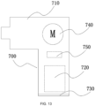
- the power tool system 10 may further include an integral power tool 700.
- the integral power tool 700 includes a housing 710, a cell module 720, and a charging terminal assembly 730.
- the integral power tool 700 is to remove the housing of the first energy supply device 100, dispose the cell module in the housing 710 of the integral power tool 700, and reserve only an interface of the charging terminal assembly 730 on the housing 710 of the integral power tool 700.
- a positive terminal and a negative terminal in the charging terminal assembly 730 of the integral power tool 700 are exposed on a surface of the housing 710.
- the charging terminal assembly 730 of the integral power tool 700 is located in hole slots of a mating portion connected to the charging apparatus.
- the integral power tool 700 may be connected to the first charging apparatus 400 or the third charging apparatus 600 and charged through the charging terminal assembly 730.
- the integral power tool 700 further includes an electric motor 740 configured to convert electrical energy into mechanical energy and output the mechanical energy to implement a specific function of the integral power tool 700 and a controller 750 configured to control operation of the electric motor 740 and manage the charge and discharge of the cell module 720.
- the cell module 120 of the integral power tool 700 adopts asymmetric capacitors or more specifically lithium-carbon capacitors as cells. Therefore, the integral power tool 700 has good performance such as a high cycle life, fast charging, low-temperature resistance, and a strong discharge ability, thereby improving the user experience.
- the integral power tool 700 may adopt the preceding charging control method and control method of the electric motor. The details are not repeated here.
- the energy supply device of the present disclosure is charged fast, resists a low temperature, and can withstand large-current discharge.
- the power tool system can be adapted to both the preceding energy supply device and a conventional battery pack.
Landscapes
- Engineering & Computer Science (AREA)
- Power Engineering (AREA)
- Mechanical Engineering (AREA)
- Secondary Cells (AREA)
- Charge And Discharge Circuits For Batteries Or The Like (AREA)
Abstract
Description
- This application claims priority to
Chinese Patent Application No. 202111411053.9 filed with the China National Intellectual Property Administration (CNIPA) on Nov. 25, 2021 - The present application relates to the field of power tools, for example, an energy supply device and a power tool system using the energy supply device.
- Power tools powered by battery packs are widely used for their convenience. A battery pack adapted to a power tool usually requires to be charged for several hours. Therefore, during use of the power tool, if the power of the battery pack is used up, a user needs to detach the battery pack from the power tool, charge the battery pack for hours, and re-mount the battery pack to the power tool for continued use, causing inconvenience to the user. Additionally, lithium battery packs, which are common on the market, have too fast a voltage drop at a low temperature below 0 °C, resulting in poor user experience.
- The present application provides an energy supply device and a power tool system.
- The present application provides an energy supply device for supplying power to a power tool. The energy supply device includes a housing detachably connected to the power tool in a mating manner and supported by the power tool; multiple cells supported by the housing of the energy supply device; a charging terminal assembly configured to be electrically connected to a charging apparatus to charge the energy supply device; and a discharge terminal assembly configured to be electrically connected to the power tool to provide electrical energy for the power tool. A charge rate of the energy supply device is greater than or equal to 6C.
- The present application provides a power tool system including a power tool, a first energy supply device, and a first charging apparatus. The power tool includes a housing detachably connected to the first energy supply device in a mating manner; a terminal assembly configured to be electrically connected to the first energy supply device to obtain electrical energy; an electric motor configured to convert the electrical energy into mechanical energy and output the mechanical energy to implement a function of the power tool; and a controller configured to control at least operation of the electric motor. The first energy supply device includes a housing detachably connected to the power tool in the mating manner and supported by the power tool; multiple cells supported by the housing of the first energy supply device; a charging terminal assembly configured to be electrically connected to the first charging apparatus to charge the first energy supply device; and a discharge terminal assembly configured to be electrically connected to the power tool to provide the electrical energy for the power tool. A charge rate of the first energy supply device is greater than or equal to 6C, and a maximum discharge rate of the first energy supply device is greater than or equal to 6C.
- The present application provides an energy supply device for supplying power to a power tool. The energy supply device includes a housing detachably connected to the power tool in a mating manner and supported by the power tool; a cell module supported by the housing of the energy supply device; a first terminal assembly configured to be electrically connected to the power tool to provide electrical energy for the power tool and be electrically connected to a first-type charging apparatus to charge the energy supply device at a first charge rate; and a second terminal assembly configured to be electrically connected to a second-type charging apparatus to charge the energy supply device at a second charge rate; where the second charge rate is greater than the first charge rate.
- The present application provides a power tool. The power tool includes a housing formed with an accommodation cavity; an electric motor accommodated in the accommodation cavity and configured to convert electrical energy into mechanical energy and output the mechanical energy to implement a function of the power tool; a cell module accommodated in the accommodation cavity and configured to provide electrical energy for at least the electric motor; a charging terminal assembly configured to be electrically connected to a charging apparatus to charge the cell module; and a controller configured to control at least operation of the electric motor and charge and discharge of the cell module. The cell module includes multiple cells, and the multiple are each a lithium-carbon capacitor.
-
-
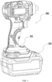
FIG. 1 is a perspective view of an energy supply device and a power tool according to an example of the present application; -
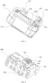
FIG. 2 is a perspective view of the energy supply device ofFIG. 1 ; -
FIG. 3 is a perspective view of the energy supply device ofFIG. 1 with a housing removed; -
FIG. 4 is a schematic view of the charging of an energy supply device according to an example of the present application; -
FIG. 5 is a circuit diagram of the energy supply device ofFIG. 4 ; -
FIG. 6 is a schematic diagram of a power tool system according to an example of the present application; -
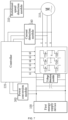
FIG. 7 is a system block diagram of a power tool according to an example of the present application; -
FIG. 8 is a flowchart of a control method of an electric motor according to an example of the present application; -
FIG. 9 is a graph of discharge voltages of a lithium-carbon capacitor and a lithium battery; -
FIG. 10 is a graph of the comparison of the case where the control method of the electric motor inFIG. 5 is used and the case where the control method of the electric motor inFIG. 5 is not used; -
FIG. 11 is a top view of a third charging apparatus according to an example of the present application; -
FIG. 12A is a perspective view of the third charging apparatus ofFIG. 11 ; -
FIG. 12B is a perspective view of the third charging apparatus ofFIG. 11 from another perspective; and -
FIG. 13 is a block diagram of a power tool according to an example of the present application. - The present disclosure is described below in conjunction with the drawings and examples.
- As shown in
FIGS. 1 to 3 , the present disclosure discloses an energy supply device, which is referred to as a firstenergy supply device 100. The firstenergy supply device 100 mainly includes ahousing 110; acell module 120 accommodated in thehousing 110 and including multiplesingle cells 121; acharging terminal assembly 130 configured to be connected to connection terminals of a first-type electronic device; and adischarge terminal assembly 140 configured to be connected to connection terminals of a second-type electronic device. The firstenergy supply device 100 is detachably connected to apower tool 300 and provides electrical energy for the power tool, such as an electric screwdriver, an electric drill, a mower, and a snow thrower. - In an example, in the shown structure, the
cell module 120 may be a 25.2 V2P cell module 120 and includes 12single cells 121 each with a nominal voltage of about 4.2 V, where sixsingle cells 121 are one series cell group, and two series cell groups are connected in parallel to form thecell module 120. In this construction, the firstenergy supply device 100 has a weight of about 1.6 kg. In other constructions, thecell module 120 may have other voltages such as 12.6 V, 21 V, and 42 V to supply power to the power tool and be charged by a charging apparatus. It is to be understood that in other constructions, the firstenergy supply device 100 may have different nominal cell voltages or may be connected with another configuration, which adopts any connection in series, connection in parallel, or connection in series and parallel. - A
single cell 121 may be a supercapacitor, which is also referred to as an electrochemical capacitor. Specifically, thesingle cell 121 is an asymmetric supercapacitor. An electrochemical capacitor based on the capacitor principle of bipolar plates is generally designed to be symmetric, two identical materials with matched masses are used for a positive electrode and a negative electrode, such as activated carbon electrodes, and the positive electrode and the negative electrode are generally not distinguished for the symmetric capacitor. Although the symmetric capacitor has a good power density and cycle life, the energy density of the symmetric capacitor is much lower than that of a lithium-ion battery, a nickel-metal hydride battery, or the like. Two electrodes of an asymmetric capacitor are made of different materials, such as a carbon material/transition metal oxide system electrode material, a carbon material/conductive polymer system electrode material, or two activated carbon electrodes with different electrochemical performance, thereby improving the energy density of the electrochemical capacitor to 80 to 120 Wh/kg. Thus, the asymmetric capacitor can be used as an energy supply unit of the power tool. In an example, thesingle cell 121 may be a lithium-carbon capacitor (LCC). The lithium-carbon capacitor is an asymmetric supercapacitor that stores energy through shallow insertion and shallow extraction of lithium ions, is a new type of energy storage device, and has good performance such as high safety of no fire and no explosion, a high cycle life of hundreds of thousands of cycles, high-rate charge and discharge, and low-temperature resistance. Therefore, theenergy supply device 100 using the lithium-carbon capacitor as thesingle cell 121 has advantages in terms of safety, charging time, service life, and the like. Compared with a conventional lithium battery, the lithium-carbon capacitor has a low internal resistance. Therefore, the internal resistance of thesingle cell 121 is greater than or equal to 0.1 mΩ and less than or equal to 4 mΩ. Optionally, the internal resistance of thesingle cell 121 is greater than or equal to 0.3 mΩ and less than or equal to 3 mΩ. Optionally, the internal resistance of thesingle cell 121 is greater than or equal to 0.5 mΩ and less than or equal to 2 mΩ. Therefore, the firstenergy supply device 100 generates a small amount of heat during use and can discharge at a large current. Optionally, the firstenergy supply device 100 can withstand continuous discharge at 6C to a maximum of 15C and transient discharge at up to 60C. Optionally, the firstenergy supply device 100 can withstand continuous discharge at 8C to a maximum of 20C and transient discharge at up to 80C. Optionally, the firstenergy supply device 100 can withstand continuous discharge at 10C to a maximum of 25C and transient discharge at up to 100C. Optionally, the firstenergy supply device 100 can withstand continuous discharge at 20C to a maximum of 50C and transient discharge at up to 200C. Optionally, the firstenergy supply device 100 can withstand continuous discharge at 40C to a maximum of 100C and transient discharge at up to 400C. For some power tools, transient discharge at a large current can cause the output of large torque to overcome resistance, thereby improving working efficiency and improving user experience. For example, when the electric drill works on a hard surface or when the snow thrower works on a road surface with deep snow, the power tool using the firstenergy supply device 100 can have strong power, greatly improving the working efficiency. Additionally, the firstenergy supply device 100 can work at a low temperature, providing a user with convenience and improving the user experience especially for power tools working outdoors, such as the snow thrower. Optionally, the working temperature of the firstenergy supply device 100 is higher than or equal to minus 35 degrees Celsius and lower than or equal to 65 degrees Celsius. Optionally, the working temperature of the firstenergy supply device 100 is higher than or equal to minus 40 degrees Celsius and lower than or equal to 70 degrees Celsius. - Depending on the volume, the capacity of a single lithium-carbon capacitor may range from 7 F to 5500 F. In this example, the
cell module 120 composed of 12single cells 121 each with a capacity of about 750 F may provide power of 9000 F, which is equivalent to a capacity of about 4 Ah. The lithium-carbon capacitor has various shapes. In this example, eachsingle cell 121 may be cylindrical. Additionally, in the firstenergy supply device 100, the length of eachsingle cell 121 may be more than twice and almost three times the diameter of thesingle cell 121. For example, eachsingle cell 121 may have a diameter of about 26 mm and a length of about 60 mm. In some constructions, eachsingle cell 121 may have a length of about 65 mm. In some constructions, eachsingle cell 121 may have a length of about 70 mm. It is to be noted that the firstenergy supply device 100 of the present disclosure may adopt the lithium-carbon capacitor in another shape, for example, a sheet-like pouch lithium-carbon capacitor. - As shown in
FIG. 3 , in this example, six cylindricalsingle cells 121 connected in series in each group may be arranged in parallel, that is to say, the axes of the cylindricalsingle cells 121 are parallel to each other. Specifically, the axes of sixsingle cells 121 may be arranged in parallel on the same plane, and the axes of the other sixsingle cells 121 may be arranged in parallel on another plane parallel to the preceding plane. That is to say, the 12single cells 121 are arranged in parallel in two layers, so as to achieve a relatively small and flat appearance. - As shown in
FIG. 2 , thehousing 110 of the firstenergy supply device 100 includes asupport portion 111 configured to be connected to the charging apparatus or the power tool. In an example, the support portion is a protrusion formed with slidingslots 112 andlocking mechanism 113 on two sides. When the energy supply device is coupled to the charging apparatus or the power tool, a mating portion of the charging apparatus or the power tool is pushed into ends of the sliding slots along an extension direction of the sliding slots until the mating portion is engaged with the locking mechanisms. In an example, the housing of the energy supply device includes twosupport portions 111 which are configured to be coupled to the charging apparatus and the power tool, respectively. As shown inFIG. 2 , the twosupport portions 111 are located on a top surface and a bottom surface of the energy supply device respectively so that the firstenergy supply device 100 can be simultaneously coupled to the charging apparatus and the power tool, thereby omitting the step in which the user needs to detach the energy supply device for charging and achieving more convenient operations.Eject buttons 114 at the top of the firstenergy supply device 100 are pressed so that the locking mechanisms can be unlocked to eject the firstenergy supply device 100. Thus, the user conveniently separates the firstenergy supply device 100 from the charging apparatus or the power tool. It is to be noted that thesupport portions 111, the lockingmechanisms 113, and theeject buttons 114 shown inFIG. 2 are only an example of a structure, and the specific shape of the housing of the energy supply device and the specific structures of the support portions, the locking mechanisms, and the eject buttons formed on the housing are not limited in the present disclosure. - In an example, the first
energy supply device 100 includes the chargingterminal assembly 130 configured to be electrically connected to the connection terminals of the first-type electronic device and thedischarge terminal assembly 140 configured to be electrically connected to the connection terminals of the second-type electronic device. The first-type electronic device is an electronic device that charges the firstenergy supply device 100 through the chargingterminal assembly 130, for example, the charging apparatus adapted to the firstenergy supply device 100. Specifically, the charging apparatus may be a dedicated charging apparatus specially used for charging the firstenergy supply device 100 or may be a universal charging apparatus capable of charging both the firstenergy supply device 100 and a common energy supply device. Since the lithium-carbon capacitor can withstand charge at a large current, the firstenergy supply device 100 has a high charge rate and a charging time calculated in minutes. In an example, the charge rate of the firstenergy supply device 100 is 6C. In an example, the charge rate of the firstenergy supply device 100 is 8C. In an example, the charge rate of the firstenergy supply device 100 is 10C. In an example, the charge rate of the firstenergy supply device 100 is 20C. In an example, the charge rate of the firstenergy supply device 100 is 30C. Compared with a common lithium-ion energy supply device, the firstenergy supply device 100 has a large charge current. For example, for the firstenergy supply device 100 with a capacity of about 4 Ah in this example, the charge rate is 6C, that is, the first energy supply device is charged at a large current of 24 A and can be fully charged in 10 minutes; the charge rate is 8C, that is, the first energy supply device is charged at a large current of 32 A and can be fully charged in 7.5 minutes; the charge rate is 10C, that is, the first energy supply device is charged at a large current of 40 A and can be fully charged in 6 minutes; the charge rate is 20C, that is, the first energy supply device is charged at a large current of 80 A and can be fully charged in 3 minutes; or the charge rate is 30C, that is, the first energy supply device is charged at a large current of 120 A and can be fully charged in 2 minutes. For the firstenergy supply device 100 with a weight of about 1.6 kg, it can be deduced according to the preceding data that in an example, the ratio of the charge current to the weight of the firstenergy supply device 100 is greater than or equal to 25 A/kg and less than or equal to 50 A/kg; in an example, the ratio of the charge current to the weight of the firstenergy supply device 100 is greater than or equal to 20 A/kg and less than or equal to 75 A/kg; in an example, the ratio of the charge current to the weight of the firstenergy supply device 100 is greater than or equal to 15 A/kg and less than or equal to 150 A/kg; in an example, the ratio of the charge current to the weight of the firstenergy supply device 100 is greater than or equal to 15 A/kg and less than or equal to 200 A/kg. - The second-type electronic device is the power tool that acquires the electrical energy through the
discharge terminal assembly 140. The firstenergy supply device 100 may support the power tool in large-current discharge and outputting large power and large torque. With the firstenergy supply device 100 with a capacity of about 4 Ah in this example as an example, the firstenergy supply device 100 can withstand a continuous discharge current of 24 A, a maximum discharge current of about 60 A, and a transient discharge current of up to 240 A. Optionally, the first battery packenergy supply device 100 can withstand a continuous discharge current of 32 A, a maximum discharge current of about 80 A, and a transient discharge current of up to 320 A. Optionally, the firstenergy supply device 100 can withstand a continuous discharge current of 40 A, a maximum discharge current of about 100 A, and a transient discharge current of up to 400 A. Optionally, the firstenergy supply device 100 can withstand a continuous discharge current of 80 A, a maximum discharge current of about 200 A, and a transient discharge current of up to 800 A. Optionally, the first battery packenergy supply device 100 can withstand a continuous discharge current of 160 A, a maximum discharge current of about 400 A, and a transient discharge current of up to 1600 A. - When the power tool is normally used, the first energy supply device intermittently discharges at a large current for a short time through the
discharge terminal assembly 140. During normal charging, the first energy supply device is continuously charged at a large current for a long time through the chargingterminal assembly 130. Therefore, in an example, the firstenergy supply device 100 adopts the chargingterminal assembly 130 and thedischarge terminal assembly 140 which are different from each other. Thedischarge terminal assembly 140 includes a dischargepositive terminal 141, a dischargenegative terminal 142, and adischarge information terminal 143. Thedischarge terminal assembly 140 is disposed in thesupport portion 111, and a positive terminal, a negative terminal, and an information terminal of the power tool are in contact with the dischargepositive terminal 141, the dischargenegative terminal 142, and thedischarge information terminal 143 throughhole slots 115 of thesupport portion 111 to implement an electrical connection. Accordingly, the chargingterminal assembly 130 includes a charging positive terminal, a charging negative terminal, and a charging information terminal. The chargingterminal assembly 130 is disposed in the otheropposite support portion 111, and a positive terminal, a negative terminal, and an information terminal of the charging apparatus are in contact with the charging positive terminal, the charging negative terminal, and the charging information terminal through hole slots of the other support portion to implement an electrical connection. The charging positive terminal and the charging negative terminal can withstand a continuous large current to ensure fast and safe charging. The design of the charging terminal assembly and the discharge terminal assembly which are independent of each other, in one aspect, can ensure the reliability and safety of large-current charging and, in the other aspect, can omit the step in which the user needs to detach the firstenergy supply device 100 for charging, achieving more convenient operations. That is to say, during charging, the user has no need to detach the firstenergy supply device 100 from the power tool and can directly connect the firstenergy supply device 100 connected to the power tool to the charging apparatus for charging. In particular, the firstenergy supply device 100 of the present disclosure has a very short charging time and can be fully charged in a few minutes, thereby omitting the step of detaching the firstenergy supply device 100 and implementing a more convenient and faster charging process. In this example, the chargingterminal assembly 130 and thedischarge terminal assembly 140 are disposed on two different surfaces of the firstenergy supply device 100, for example, the top surface and the bottom surface which are opposite, so that the power tool and the charging apparatus simultaneously connected to the firstenergy supply device 100 are staggered in space, thereby avoiding interference. - In another example, a first
energy supply device 100 has two charging modes. In a first charging mode, the firstenergy supply device 100 is connected to a first charging apparatus and charged at a first charge rate; in a second charging mode, the firstenergy supply device 100 is connected to a second charging apparatus and charged at a second charge rate, where the second charge rate is greater than the first charge rate. As shown inFIG. 4 , specifically, the firstenergy supply device 100 is the same as the preceding firstenergy supply device 100 in other aspects than terminal assemblies. The firstenergy supply device 100 in this example has a firstterminal assembly 150 and a secondterminal assembly 160. - The first
terminal assembly 150 is similar to a terminal assembly of a common lithium battery pack and may be used for charging the firstenergy supply device 100 and discharging the firstenergy supply device 100. Specifically, the firstterminal assembly 150 of the firstenergy supply device 100 may include apositive terminal 151, anegative terminal 152, and aninformation terminal 153. The firstterminal assembly 150 is disposed in thesupport portion 111. When the firstenergy supply device 100 is connected to the power tool, the positive terminal, the negative terminal, and the information terminal of the power tool are in contact with thepositive terminal 151, thenegative terminal 152, and theinformation terminal 153 through thehole slots 115 of thesupport portion 111 to implement an electrical connection. When the firstenergy supply device 100 is connected to a first-type charging apparatus, a positive terminal, a negative terminal, and an information terminal of the first-type charging apparatus are in contact with thepositive terminal 151, thenegative terminal 152, and theinformation terminal 153 through thehole slots 115 of thesupport portion 111 to implement an electrical connection. Optionally, the first charge rate at which the firstenergy supply device 100 is charged through the firstterminal assembly 150 is less than or equal to 5C. Optionally, the first charge rate at which the firstenergy supply device 100 is charged through the firstterminal assembly 150 is less than or equal to 4C. Optionally, the first charge rate at which the firstenergy supply device 100 is charged through the firstterminal assembly 150 is less than or equal to 3C. - The second
terminal assembly 160 may be contact charging terminals with a relatively large diameter, which are exposed on a surface of the firstenergy supply device 100 and support large-current charging. Specifically, the secondterminal assembly 160 may include apositive charging terminal 161 and anegative charging terminal 162. The secondterminal assembly 160 may include a separate information terminal (not shown), or a communication signal is superimposed on the positive terminal for transmission. In an example, the secondterminal assembly 160 and the firstterminal assembly 150 are disposed on two different surfaces of the firstenergy supply device 100, for example, a bottom surface and a top surface which are opposite, so that the power tool and the charging apparatus simultaneously connected to the firstenergy supply device 100 are staggered in space, thereby avoiding interference. Moreover, since the secondterminal assembly 160 is exposed on the surface of the firstenergy supply device 100, the firstenergy supply device 100 to be charged only needs to be placed on aconnection portion 402 of a second-type charging apparatus 401 so that thepositive charging terminal 161 and thenegative charging terminal 162 are in contact with apositive terminal 403 and anegative terminal 404 of the second-type charging apparatus 401 respectively, and the firstenergy supply device 100 does not need to be detached from the power tool, thereby simplifying operation steps for charging and providing the user with convenience of charging in a gap during use of the power tool. Optionally, the second charge rate at which the firstenergy supply device 100 is charged through the secondterminal assembly 160 is greater than or equal to 6C. Optionally, the second charge rate at which the firstenergy supply device 100 is charged through the secondterminal assembly 160 is greater than or equal to 8C. Optionally, the second charge rate at which the firstenergy supply device 100 is charged through the secondterminal assembly 160 is greater than or equal to 10C. In an example, the second charge rate at which the firstenergy supply device 100 is charged through the secondterminal assembly 160 is greater than or equal to twice the first charge rate at which the firstenergy supply device 100 is charged through the firstterminal assembly 150. - Since the second
terminal assembly 160 is exposed to the outside, a short circuit between thepositive charging terminal 161 and thenegative charging terminal 162 of the secondterminal assembly 160 needs to be prevented. Generally, the setting of a diode can limit a flow direction of a current and prevent the current from flowing from a positive electrode of thecell module 120 to thepositive charging terminal 161, thereby avoiding the short circuit. However, during normal charging, a large amount of heat is generated when the current flows through the diode, resulting in low energy efficiency during charging. As shown inFIG. 5 , in an example, acontroller 165 and asemiconductor element 164 such as a metal-oxide-semiconductor field-effect transistor (MOSFET) are used to control the charging of the firstenergy supply device 100. Thecontroller 165 is connected to a control terminal of thesemiconductor element 164 and controls thesemiconductor element 164 through the control terminal. Thesemiconductor element 164 is connected between thepositive charging terminal 161 and the positive electrode of thecell module 120 through two switching terminals. In a normal state, the two switching terminals of thesemiconductor element 164 are unidirectionally on from thepositive charging terminal 161 to the positive electrode of thecell module 120 through a parasitic diode, so as to prevent the current from flowing from thecell module 120 to thepositive charging terminal 161. In an example, thecontroller 165 separately detects a voltage of the positive electrode of thecell module 120 and a voltage of thepositive charging terminal 161; when the voltage of thepositive charging terminal 161 is greater than the voltage of the positive electrode of thecell module 120, thecontroller 165 controls thesemiconductor element 164 through the control terminal to make the semiconductor element bidirectionally on so that a charge current from the second-type charging apparatus 401 flows from thepositive charging terminal 161 to the positive electrode of thecell module 120 to charge the firstenergy supply device 100. - As shown in
FIG. 6 , the present disclosure further discloses apower tool system 10 including apower tool 300 such as an electric drill. It is to be understood that thepower tool 300 may be another torque output power tool such as an electric screwdriver or an electric hammer; thepower tool 300 may be a grinding power tool such as an angle grinder; thepower tool 300 may be a sawing power tool such as a jigsaw, a reciprocating saw, and an electric circular saw; or thepower tool 300 may be a walking power tool such as a mower or a snow thrower. Thepower tool 300 has ahousing 301 detachably connected to an energy supply device, anelectric motor 310 configured to convert electrical energy into mechanical energy to implement a function of the power tool, and acontroller 320 configured to control at least the rotation of the electric motor. Different power tools may adopt different housings, electric motors, controllers, and the like. It is to be understood that power tools with different shapes, structures, and functions each have a mating portion connected to a support portion of the energy supply device in a mating manner and a terminal assembly electrically connected to a terminal assembly of the energy supply device. That is to say, in thepower tool system 10, different power tools have the same power interface. The terminal assembly includes a positive terminal, a negative terminal, and an information terminal, which are configured to be connected to a positive terminal, a negative terminal, and an information terminal of the energy supply device, respectively. - The
power tool system 10 further includes a firstenergy supply device 100 and a secondenergy supply device 200. A difference between the firstenergy supply device 100 and the secondenergy supply device 200 is mainly different chemical principles. For example, the firstenergy supply device 100 uses the preceding lithium-carbon capacitor as a charge and discharge unit, and the secondenergy supply device 200 uses a common lithium battery as a charge and discharge unit. Specifically, the secondenergy supply device 200 may be a lithium battery pack. The firstenergy supply device 100 is not limited to a single model. That is to say, the firstenergy supply device 100 may include multiple firstenergy supply devices 100 of different models. For example, the firstenergy supply device 100 may include an energy supply device with a nominal voltage of 21 V, an energy supply device with a nominal voltage of 42 V, or an energy supply device with another nominal voltage. The firstenergy supply device 100 may be a 1P energy supply device or a 2P or 3P energy supply device. The charge rate of the firstenergy supply device 100 may be 10C, 20C, or 30C. That is to say, in thepower tool system 10, energy supply devices with lithium-carbon capacitors as cell modules are collectively referred to as the firstenergy supply device 100. Similarly, the secondenergy supply device 200 is also not limited to a single model. That is to say, the secondenergy supply device 200 may include multiple secondenergy supply devices 200 of different models. For example, the secondenergy supply device 200 may include an energy supply device with a nominal voltage of 21 V, an energy supply device with a nominal voltage of 42 V, or an energy supply device with another nominal voltage. The secondenergy supply device 200 may be a 1P energy supply device or a 2P or 3P energy supply device. That is to say, in thepower tool system 10, energy supply devices based on lithium batteries are collectively referred to as the secondenergy supply device 200. In this manner, a user may flexibly select, according to requirements of the user, the firstenergy supply device 100 or the secondenergy supply device 200 of a different model. - It is to be understood that the first
energy supply devices 100 of different models have the same charging terminal assembly and the same discharge terminal assembly. That is to say, the firstenergy supply devices 100 of different models have the same discharge interface. Sincedifferent power tools 300 have the same power interface, all the firstenergy supply devices 100 may be configured to supply power to thepower tools 300 in thepower tool system 10. Similarly, the secondenergy supply devices 200 of different models have the same terminal assembly. Different from the firstenergy supply device 100, the charging terminal assembly and the discharge terminal assembly are not distinguished for the secondenergy supply device 200. That is to say, the terminal assembly of the secondenergy supply device 200 may be used for charging the secondenergy supply device 200 and discharging the secondenergy supply device 200. Specifically, the terminal assembly of the secondenergy supply device 200 may include a positive terminal, a negative terminal, and an information terminal. Therefore, the secondenergy supply devices 200 of different models have the same discharge interface, and all the secondenergy supply devices 200 may be configured to supply power to thepower tools 300 in thepower tool system 10. It is to be noted that the discharge terminal assembly of the firstenergy supply device 100 is similar to the terminal assembly of the secondenergy supply device 200 so that the terminal assembly of thepower tool 300 can be compatible with both the discharge terminal assembly of the firstenergy supply device 100 and the terminal assembly of the secondenergy supply device 200. That is to say, the terminal assembly of thepower tool 300 may be electrically connected to both the discharge terminal assembly of the firstenergy supply device 100 and the terminal assembly of the secondenergy supply device 200, thereby implementing the switching between the firstenergy supply device 100 and the secondenergy supply device 200 and providing the user with more diverse options. - When the
power tool 300 is connected to the firstenergy supply device 100, the positive terminal, the negative terminal, and the information terminal in the terminal assembly of thepower tool 300 are configured to be connected to a discharge positive terminal, a discharge negative terminal, and a discharge information terminal in the discharge terminal assembly of the firstenergy supply device 100, respectively. When thepower tool 300 is connected to the secondenergy supply device 200, the positive terminal, the negative terminal, and the information terminal in the terminal assembly of thepower tool 300 are configured to be connected to the positive terminal, the negative terminal, and the information terminal in the terminal assembly of the secondenergy supply device 200, respectively. Thecontroller 320 of thepower tool 300 may determine, according to a signal received through the information terminal, whether the firstenergy supply device 100 or the secondenergy supply device 200 is connected to thepower tool 300. For example, a circuit of the firstenergy supply device 100 further includes a first identification resistor (not shown), and thecontroller 320 identifies the firstenergy supply device 100 through the first identification resistor. Optionally, a specific model of the firstenergy supply device 100 is identified. When determining that thepower tool 300 is electrically connected to the firstenergy supply device 100 at present, thecontroller 320 of thepower tool 300 controls theelectric motor 310 by a first control method, and when determining that thepower tool 300 is electrically connected to the secondenergy supply device 200 at present, thecontroller 320 of thepower tool 300 controls theelectric motor 310 by a second control method, where the first control method is different from the second control method. - Referring to the discharge curves of the lithium-carbon capacitor and the lithium battery shown in
FIG. 9 , a relationship between voltage and capacity of the lithium-carbon capacitor is shown by a solid line, and a relationship between voltage and capacity of the lithium battery is shown by a dashed line. It is to be understood that, unlike a relatively stable voltage platform of the lithium battery, the voltage value of the lithium-carbon capacitor decreases with a decrease in capacity. Thus, when the firstenergy supply device 100 is used for power supply, thepower tool 300 has poor experience: strong power at the beginning and gradually reduced power without staying power during use. Referring to the system block diagram ofFIG. 7 and the flowchart ofFIG. 8 , to alleviate this problem and improve user experience, thecontroller 320 adopts the control method below. - In S1, a voltage V1 of the first
energy supply device 100 is acquired. - The
power tool 300 includes avoltage detection module 330, and thevoltage detection module 330 detects the voltage of the firstenergy supply device 100 and sends the voltage to thecontroller 320. - In S2, it is determined whether an average voltage V1/n of a
single cell 121 is greater than or equal to a first voltage threshold V0. - n denotes the number of
single cells 121 connected in series in the firstenergy supply device 100, and V1/n denotes the average voltage of thesingle cell 121 in the firstenergy supply device 100. V0 is the first voltage threshold. In this example, V0 is equal to 3.7 V, and V0 may be other values. Thecontroller 320 calculates and determines whether the average voltage V1/n of thesingle cell 121 is greater than or equal to the first voltage threshold V0. When V1/n is greater than or equal to V0, S3 is performed. Otherwise, S7 is performed. - In S3, an actual rotational speed w of the
electric motor 310 is acquired. - The
controller 320 detects the actual rotational speed w of theelectric motor 310 through a rotationalspeed detection module 350. A method for acquiring the actual rotational speed w of theelectric motor 310 is not described in detail here. Specifically, the rotational speed of theelectric motor 310 may be detected in a manner such as a Hall sensor, a back electromotive force method, and the measurement of winding currents of the electric motor. - In S4, it is determined whether the ratio w/w0 of the actual rotational speed w of the electric motor to an idle rotational speed w0 of the electric motor is greater than or equal to a locked-rotor threshold z.
- The
controller 320 determines, according to the ratio of the actual rotational speed w to the idle rotational speed w0 of theelectric motor 310, whether theelectric motor 310 has a locked rotor. The threshold z for determining the locked rotor may be different values according to different power tools and electric motors, such as 1/4, 1/5, and 1/6. When w/w0 is greater than or equal to z, S5 is performed. Otherwise, S6 is performed. - In S5, a current is restricted to a first
current threshold 10. - According to an actual current fed back by a
current detection module 340 and the first current threshold I0, the current through theelectric motor 310 is restricted to being less than or equal to the first current threshold I0, so as to slow down a voltage drop speed of the firstenergy supply device 100. - In S6, the current is not restricted, and large torque is outputted.
- Since the actual rotational speed w of the
electric motor 310 is too low, it may be considered that theelectric motor 310 is in or nearly in a locked-rotor state. In this case, the current is not restricted, and the large torque is outputted to overcome the locked rotor. - In S7, a voltage utilization rate is increased.
- In this case, the voltage of the first
energy supply device 100 is relatively low, and the voltage utilization rate needs to be increased by a modulation method of the electric motor, so as to optimize the rotational speed and load capacity of the electric motor and improve the user experience. Specifically, different control methods are used according to different electric motors. For a brushless direct current (BLDC) electric motor, manners of extending a conduction band and adding a lead angle may be used, for example, a conduction band of 120° is extended to a conduction band of 150° or 180°, and a lead angle of 15° or 30° is added. For a permanent-magnet synchronous motor (PMSM), over-modulation and field weakening methods may be used to increase the torque and current. Finally, thecontroller 320 controls, according to a calculation result in the preceding control method, switches in a driver circuit of the electric motor to be turned on or off. - In the preceding control manner of the electric motor, the voltage of the first
energy supply device 100 can decrease more slowly, and when the voltage of the firstenergy supply device 100 is insufficient, an effect of the insufficient voltage on the rotational speed and load capacity of thepower tool 300 can be reduced, thereby improving the user experience. As shown inFIG. 10 , a solid line represents a relationship between the rotational speed of the electric motor and the remaining capacity of the energy supply device in a common control method of the electric motor where no adjustment is made for the firstenergy supply device 100, and a dashed line represents a relationship between the rotational speed of the electric motor and the remaining capacity of the energy supply device in the preceding control method of the electric motor. It can be seen that when the control manner is not used, although the electric motor has a higher rotational speed when the firstenergy supply device 100 has sufficient power, the rotational speed of the electric motor decreases significantly as the power decreases; when the control manner is used, although the electric motor has a slightly lower rotational speed when the firstenergy supply device 100 has sufficient power, the rotational speed of the electric motor decreases at a smaller slope as the power decreases, that is, the rotational speed decreases more gently, and the voltage utilization rate is increased when the voltage is insufficient, thereby increasing, to a certain degree, the rotational speed when the voltage is insufficient. It is to be noted that fordifferent power tools 300 and differentelectric motors 310, specific thresholds and/or parameters in the preceding control method may be different. - The
power tool system 10 further includes afirst charging apparatus 400 and asecond charging apparatus 500, which are configured to charge the firstenergy supply device 100 and the secondenergy supply device 200, respectively. As described above, the firstenergy supply devices 100 of different models have the same chargingterminal assembly 130 and the samedischarge terminal assembly 140. Therefore, the first energy supply devices of different models have the same charging interface and can be charged by the same charging apparatus. Thefirst charging apparatus 400 is a large-current charging apparatus and charges the firstenergy supply device 100 when connected to the chargingterminal assembly 130 of the firstenergy supply device 100. As described above, the secondenergy supply devices 200 of different models have the same terminal assembly. Therefore, the secondenergy supply devices 200 of different models have the same charging interface and can be charged by the same charging apparatus. Thesecond charging apparatus 500 may be a common apparatus for charging the lithium battery pack, such as a charging base or a charging pile. A terminal assembly of thefirst charging apparatus 400 is matched with the chargingterminal assembly 130 of the firstenergy supply device 100, and a terminal assembly of thesecond charging apparatus 500 is matched with the terminal assembly of the secondenergy supply device 200. It is to be noted that some firstenergy supply devices 100 have two terminal assemblies capable of being charged, that is to say, some firstenergy supply devices 100 include a firstterminal assembly 150 for slow charging and a secondterminal assembly 160 for fast charging. For these firstenergy supply devices 100, thefirst charging apparatus 400 of thepower tool system 10 may charge the firstenergy supply device 100 through the secondterminal assembly 160, and thesecond charging apparatus 500 of thepower tool system 10 may charge the firstenergy supply device 100 through the firstterminal assembly 150. - Optionally, the
power tool system 10 further includes athird charging apparatus 600, and thethird charging apparatus 600 is a universal charging apparatus capable of charging both the firstenergy supply device 100 and the secondenergy supply device 200. As shown inFIGS. 11 and12 , thethird charging apparatus 600 has two support portions, which are afirst support portion 611 capable of supporting the firstenergy supply device 100 and asecond support portion 612 capable of supporting the secondenergy supply device 200, respectively. In an example, the two support portions may be arranged back to back. In other examples, the two support portions may be arranged in parallel or in other manners. A firstterminal assembly 621 is disposed on the first support portion 610 and configured to be electrically connected to the chargingterminal assembly 130 of the firstenergy supply device 100. A secondterminal assembly 622 is disposed on the second support portion and configured to be electrically connected to the terminal assembly of the secondenergy supply device 200. In an example, thethird charging apparatus 600 has two charging circuits (not shown): a first charging circuit configured to charge the firstenergy supply device 100; and a second charging circuit configured to charge the secondenergy supply device 200. Optionally, the first charging circuit is disposed on a first printed circuit board assembly (PCBA), and the second charging circuit is disposed on a second PCBA. The two PCBAs are encapsulated in a housing of thethird charging apparatus 600, which is equivalent to two mutually independent chargers in thethird charging apparatus 600, which do not interfere with each other. In another example, after AC-DC, two DC-DC circuits may be used for charging the firstenergy supply device 100 and the secondenergy supply device 200, respectively. When the firstterminal assembly 621 is electrically connected to the chargingterminal assembly 130 of the firstenergy supply device 100, the first charging circuit charges the firstenergy supply device 100; when the secondterminal assembly 622 is electrically connected to the terminal assembly of the secondenergy supply device 200, the second charging circuit charges the secondenergy supply device 200. The first charging circuit and the second charging circuit are capable of simultaneously charging the firstenergy supply device 100 and the secondenergy supply device 200. - Optionally, the
power tool system 10 may further include anintegral power tool 700. As shown inFIG. 13 , theintegral power tool 700 includes ahousing 710, acell module 720, and a chargingterminal assembly 730. Essentially, theintegral power tool 700 is to remove the housing of the firstenergy supply device 100, dispose the cell module in thehousing 710 of theintegral power tool 700, and reserve only an interface of the chargingterminal assembly 730 on thehousing 710 of theintegral power tool 700. Optionally, a positive terminal and a negative terminal in the chargingterminal assembly 730 of theintegral power tool 700 are exposed on a surface of thehousing 710. Optionally, the chargingterminal assembly 730 of theintegral power tool 700 is located in hole slots of a mating portion connected to the charging apparatus. Theintegral power tool 700 may be connected to thefirst charging apparatus 400 or thethird charging apparatus 600 and charged through the chargingterminal assembly 730. Theintegral power tool 700 further includes anelectric motor 740 configured to convert electrical energy into mechanical energy and output the mechanical energy to implement a specific function of theintegral power tool 700 and acontroller 750 configured to control operation of theelectric motor 740 and manage the charge and discharge of thecell module 720. Thecell module 120 of theintegral power tool 700 adopts asymmetric capacitors or more specifically lithium-carbon capacitors as cells. Therefore, theintegral power tool 700 has good performance such as a high cycle life, fast charging, low-temperature resistance, and a strong discharge ability, thereby improving the user experience. Theintegral power tool 700 may adopt the preceding charging control method and control method of the electric motor. The details are not repeated here. - The energy supply device of the present disclosure is charged fast, resists a low temperature, and can withstand large-current discharge. The power tool system can be adapted to both the preceding energy supply device and a conventional battery pack.
- Those of ordinary skill in the art can make changes or variations in other different forms based on the preceding description.
Claims (30)
- An energy supply device for supplying power to a power tool, comprising:a housing detachably connected to the power tool in a mating manner and supported by the power tool;a plurality of cells supported by the housing of the energy supply device;a charging terminal assembly configured to be electrically connected to a charging apparatus to charge the energy supply device; anda discharge terminal assembly configured to be electrically connected to the power tool to provide electrical energy for the power tool;wherein a charge rate of the energy supply device is greater than or equal to 6C.
- The energy supply device according to claim 1, wherein each of the plurality of cells has a resistance greater than or equal to 0.3 mΩ and less than or equal to 3 mΩ.
- The energy supply device according to claim 1, wherein a ratio of a charge current of the energy supply device to a weight of the energy supply device is greater than or equal to 15 A/kg and less than or equal to 200 A/kg.
- The energy supply device according to claim 1, wherein a maximum discharge rate of the energy supply device is greater than or equal to 6C.
- The energy supply device according to claim 1, wherein the plurality of cells are each an asymmetric supercapacitor.
- The energy supply device according to claim 1, wherein the plurality of cells are each a lithium-carbon capacitor.
- The energy supply device according to claim 1, wherein a working temperature of the energy supply device is higher than or equal to minus 40 degrees Celsius and lower than or equal to 70 degrees Celsius.
- The energy supply device according to claim 1, wherein the charging terminal assembly and the discharge terminal assembly are different components, and the energy supply device is capable of being charged by the charging apparatus when the energy supply device is connected to the power tool in the mating manner.
- The energy supply device according to claim 1, wherein a maximum discharge current of the energy supply device is about 400 A.
- The energy supply device according to claim 1, wherein the power tool is an electric drill or a snow thrower.
- A power tool system, comprising a power tool, a first energy supply device, and a first charging apparatus;
wherein the power tool comprises:a housing detachably connected to the first energy supply device in a mating manner;a terminal assembly configured to be electrically connected to the first energy supply device to obtain electrical energy;an electric motor configured to convert the electrical energy into mechanical energy and output the mechanical energy to implement a function of the power tool; anda controller configured to control at least operation of the electric motor;wherein the first energy supply device comprises:a housing detachably connected to the power tool in the mating manner and supported by the power tool;a plurality of cells supported by the housing of the first energy supply device;a charging terminal assembly configured to be electrically connected to the first charging apparatus to charge the first energy supply device; anda discharge terminal assembly configured to be electrically connected to the power tool to provide the electrical energy for the power tool;wherein a charge rate of the first energy supply device is greater than or equal to 6C, and a maximum discharge rate of the first energy supply device is greater than or equal to 6C. - The power tool system according to claim 11, wherein the plurality of cells are each an asymmetric supercapacitor.
- The power tool system according to claim 11, wherein the plurality of cells are each a lithium-carbon capacitor.
- The power tool system according to claim 11, wherein a ratio of a charge current of the first energy supply device to a weight of the first energy supply device is greater than or equal to 15 A/kg and less than or equal to 200 A/kg.
- The power tool system according to claim 11, wherein when the power tool is connected to the first energy supply device, the controller controls the electric motor according to at least a voltage of the first energy supply device, and when the voltage of the first energy supply device is greater than or equal to a first voltage threshold, restricts a current of the electric motor to a first current threshold.
- The power tool system according to claim 11, wherein the first energy supply device further comprises a first identification resistor, and the controller identifies the first energy supply device through the first identification resistor.
- The power tool system according to claim 11, wherein the charging terminal assembly and the discharge terminal assembly of the first energy supply device are different components, and when the first energy supply device is connected to the power tool in the mating manner, the first energy supply device is capable of being charged by the first charging apparatus.
- The power tool system according to claim 11, further comprising a second energy supply device and a second charging apparatus;
wherein the second energy supply device comprises:a housing detachably connected to the power tool in the mating manner and supported by the power tool;a plurality of lithium cells supported by the housing of the second energy supply device; anda terminal assembly configured to be electrically connected to the power tool to provide the electrical energy for the power tool or be electrically connected to the second charging apparatus to charge the second energy supply device. - The power tool system according to claim 18, wherein when the power tool is connected to the first energy supply device, the controller controls the electric motor by a first control method, and when the power tool is connected to the second energy supply device, the controller controls the electric motor by a second control method, wherein the first control method is different from the second control method.
- The power tool system according to claim 18, further comprising:
a third charging apparatus comprising:a first terminal assembly configured to be electrically connected to the charging terminal assembly of the first energy supply device;a second terminal assembly configured to be electrically connected to the terminal assembly of the second energy supply device;a first charging circuit configured to charge the first energy supply device; anda second charging circuit configured to charge the second energy supply device;wherein when the first terminal assembly is electrically connected to the charging terminal assembly of the first energy supply device, the first charging circuit charges the first energy supply device; when the second terminal assembly is electrically connected to the terminal assembly of the second energy supply device, the second charging circuit charges the second energy supply device; and the first charging circuit and the second charging circuit are capable of simultaneously charging the first energy supply device and the second energy supply device. - An energy supply device for supplying power to a power tool, comprising:a housing detachably connected to the power tool in a mating manner and supported by the power tool;a cell module supported by the housing of the energy supply device;a first terminal assembly configured to be electrically connected to the power tool to provide electrical energy for the power tool and be electrically connected to a first-type charging apparatus to charge the energy supply device at a first charge rate; anda second terminal assembly configured to be electrically connected to a second-type charging apparatus to charge the energy supply device at a second charge rate;wherein the second charge rate is greater than the first charge rate.
- The energy supply device according to claim 21, wherein the second terminal assembly comprises a positive charging terminal and a negative charging terminal, wherein the positive charging terminal and the negative charging terminal are exposed on a surface of the housing.
- The energy supply device according to claim 21, wherein the first charge rate is less than or equal to 5C; and the second charge rate is greater than or equal to 6C.
- The energy supply device according to claim 21, wherein the second charge rate is greater than or equal to twice the second charge rate.
- The energy supply device according to claim 21, wherein when the energy supply device is connected to the power tool in the mating manner, the energy supply device is capable of being charged through the second terminal assembly.
- The energy supply device according to claim 22, further comprising a controller and a semiconductor element, wherein the controller is electrically connected to the semiconductor element and detects at least a voltage of a positive electrode of the cell module and a voltage of the positive charging terminal; and when the voltage of the positive charging terminal is greater than the voltage of the positive electrode of the cell module, the semiconductor element is turned on.
- The energy supply device according to claim 26, wherein when the voltage of the positive charging terminal is less than the voltage of the positive electrode of the cell module, the semiconductor element prevents a current from flowing from the cell module to the positive charging terminal.
- The energy supply device according to claim 21, wherein the cell module comprises a plurality of cells, and the plurality of cells are each an asymmetric supercapacitor.
- The energy supply device according to claim 28, wherein the plurality of cells are each a lithium-carbon capacitor.
- A power tool, comprising:a housing formed with an accommodation cavity;an electric motor accommodated in the accommodation cavity and configured to convert electrical energy into mechanical energy and output the mechanical energy to implement a function of the power tool;a cell module accommodated in the accommodation cavity and configured to provide electrical energy for at least the electric motor;a charging terminal assembly configured to be electrically connected to a charging apparatus to charge the cell module; anda controller configured to control at least operation of the electric motor and charge and discharge of the cell module;wherein the cell module comprises a plurality of cells, and the plurality of cells are each a lithium-carbon capacitor.
Applications Claiming Priority (2)
| Application Number | Priority Date | Filing Date | Title |
|---|---|---|---|
| CN202111411053 | 2021-11-25 | ||
| PCT/CN2022/133095 WO2023093656A1 (en) | 2021-11-25 | 2022-11-21 | Energy supply apparatus and electric tool system |
Publications (3)
| Publication Number | Publication Date |
|---|---|
| EP4391284A1 true EP4391284A1 (en) | 2024-06-26 |
| EP4391284A4 EP4391284A4 (en) | 2025-03-19 |
| EP4391284B1 EP4391284B1 (en) | 2025-12-24 |
Family
ID=86538840
Family Applications (1)
| Application Number | Title | Priority Date | Filing Date |
|---|---|---|---|
| EP22897739.3A Active EP4391284B1 (en) | 2021-11-25 | 2022-11-21 | Energy supply apparatus and electric tool system |
Country Status (4)
| Country | Link |
|---|---|
| US (1) | US20240208026A1 (en) |
| EP (1) | EP4391284B1 (en) |
| CN (1) | CN118235307A (en) |
| WO (1) | WO2023093656A1 (en) |
Family Cites Families (7)
| Publication number | Priority date | Publication date | Assignee | Title |
|---|---|---|---|---|
| CN105162225B (en) * | 2015-09-06 | 2019-03-05 | 盐城工学院 | A kind of outer mixed via Self-reconfiguration super capacitance cell circuit and control method for quickly charging |
| CN206259722U (en) * | 2016-11-18 | 2017-06-16 | 凌容新能源科技(上海)股份有限公司 | A kind of electrical equipment of quick charge |
| CN109861368A (en) * | 2017-11-30 | 2019-06-07 | 苏州宝时得电动工具有限公司 | Power supply unit and power tool with same |
| CN208400721U (en) * | 2018-03-21 | 2019-01-18 | 博世电动工具(中国)有限公司 | Superbattery packet and electric tool component |
| WO2020168416A1 (en) * | 2019-02-21 | 2020-08-27 | Omachron Intellectual Property Inc. | Cordless appliance, such as a surface cleaning apparatus, and a charging unit therefor |
| CN112259866A (en) * | 2020-11-06 | 2021-01-22 | 格力博(江苏)股份有限公司 | Battery pack, electric tool and system |
| CN112927951B (en) * | 2021-03-04 | 2022-09-23 | 富华德电子(东莞)有限公司 | A kind of synthetic method of soft-pack lithium-carbon capacitor |
-
2022
- 2022-11-21 CN CN202280069828.5A patent/CN118235307A/en active Pending
- 2022-11-21 EP EP22897739.3A patent/EP4391284B1/en active Active
- 2022-11-21 WO PCT/CN2022/133095 patent/WO2023093656A1/en not_active Ceased
-
2024
- 2024-03-12 US US18/602,181 patent/US20240208026A1/en active Pending
Also Published As
| Publication number | Publication date |
|---|---|
| EP4391284A4 (en) | 2025-03-19 |
| CN118235307A (en) | 2024-06-21 |
| WO2023093656A1 (en) | 2023-06-01 |
| US20240208026A1 (en) | 2024-06-27 |
| EP4391284B1 (en) | 2025-12-24 |
Similar Documents
| Publication | Publication Date | Title |
|---|---|---|
| US9786877B2 (en) | Battery pack of electric power tool | |
| Barsukov et al. | Battery power management for portable devices | |
| EP2195902B1 (en) | Circuit arrangement with multiple batteries | |
| CN101675555B (en) | Battery pack and battery system | |
| CN103580110B (en) | Adapter and electric tool | |
| JP6408912B2 (en) | Hybrid battery system | |
| EP2269262B1 (en) | Leadless starting accumulator battery, processing method and its use, particularly for combustion engines and motor vehicles | |
| US20160303989A1 (en) | Portable backup charger | |
| CN102306943A (en) | Lithium ion battery management system | |
| WO1997012415A1 (en) | Hybrid energy storage system | |
| JP2011530271A (en) | Lithium ion battery pack charging system and apparatus including the same | |
| WO2012074548A1 (en) | Lithium starter battery and solid state switch therefor | |
| JP2002510850A (en) | Battery with built-in controller | |
| JP2005150079A (en) | Battery pack | |
| CN102624312A (en) | Hybrid inverter generator | |
| CN103038974A (en) | Advanced rechargeable battery system | |
| CN1659759A (en) | Charger for rechargeable batteries | |
| KR20100061714A (en) | Assembled battery and battery system | |
| CN108110819A (en) | Expandable portable power supply | |
| AU2021254599A1 (en) | Battery pack with temperature limited current | |
| KR20210073563A (en) | Power tool power source with vehicle start function | |
| US20250158141A1 (en) | Battery pack for supplying electric power to a power tool | |
| JP5705046B2 (en) | Power system | |
| EP4391284B1 (en) | Energy supply apparatus and electric tool system | |
| CN114883732B (en) | An intelligent output battery pack |
Legal Events
| Date | Code | Title | Description |
|---|---|---|---|
| STAA | Information on the status of an ep patent application or granted ep patent |
Free format text: STATUS: THE INTERNATIONAL PUBLICATION HAS BEEN MADE |
|
| PUAI | Public reference made under article 153(3) epc to a published international application that has entered the european phase |
Free format text: ORIGINAL CODE: 0009012 |
|
| STAA | Information on the status of an ep patent application or granted ep patent |
Free format text: STATUS: REQUEST FOR EXAMINATION WAS MADE |
|
| 17P | Request for examination filed |
Effective date: 20240319 |
|
| AK | Designated contracting states |
Kind code of ref document: A1 Designated state(s): AL AT BE BG CH CY CZ DE DK EE ES FI FR GB GR HR HU IE IS IT LI LT LU LV MC ME MK MT NL NO PL PT RO RS SE SI SK SM TR |
|
| RIC1 | Information provided on ipc code assigned before grant |
Ipc: H01M 50/24 20210101ALI20241119BHEP Ipc: B25F 5/00 20060101ALI20241119BHEP Ipc: H02J 7/34 20060101ALI20241119BHEP Ipc: H02J 7/00 20060101AFI20241119BHEP |
|
| DAV | Request for validation of the european patent (deleted) | ||
| DAX | Request for extension of the european patent (deleted) | ||
| A4 | Supplementary search report drawn up and despatched |
Effective date: 20250217 |
|
| RIC1 | Information provided on ipc code assigned before grant |
Ipc: H01M 50/24 20210101ALI20250211BHEP Ipc: B25F 5/00 20060101ALI20250211BHEP Ipc: H02J 7/34 20060101ALI20250211BHEP Ipc: H02J 7/00 20060101AFI20250211BHEP |
|
| GRAP | Despatch of communication of intention to grant a patent |
Free format text: ORIGINAL CODE: EPIDOSNIGR1 |
|
| STAA | Information on the status of an ep patent application or granted ep patent |
Free format text: STATUS: GRANT OF PATENT IS INTENDED |
|
| GRAS | Grant fee paid |
Free format text: ORIGINAL CODE: EPIDOSNIGR3 |
|
| GRAA | (expected) grant |
Free format text: ORIGINAL CODE: 0009210 |
|
| STAA | Information on the status of an ep patent application or granted ep patent |
Free format text: STATUS: THE PATENT HAS BEEN GRANTED |
|
| INTG | Intention to grant announced |
Effective date: 20251023 |
|
| AK | Designated contracting states |
Kind code of ref document: B1 Designated state(s): AL AT BE BG CH CY CZ DE DK EE ES FI FR GB GR HR HU IE IS IT LI LT LU LV MC ME MK MT NL NO PL PT RO RS SE SI SK SM TR |
|
| REG | Reference to a national code |
Ref country code: CH Ref legal event code: F10 Free format text: ST27 STATUS EVENT CODE: U-0-0-F10-F00 (AS PROVIDED BY THE NATIONAL OFFICE) Effective date: 20251224 Ref country code: GB Ref legal event code: FG4D |
|
| REG | Reference to a national code |
Ref country code: DE Ref legal event code: R096 Ref document number: 602022027643 Country of ref document: DE |
|
| REG | Reference to a national code |
Ref country code: LT Ref legal event code: MG9D |
|
| PG25 | Lapsed in a contracting state [announced via postgrant information from national office to epo] |
Ref country code: NO Free format text: LAPSE BECAUSE OF FAILURE TO SUBMIT A TRANSLATION OF THE DESCRIPTION OR TO PAY THE FEE WITHIN THE PRESCRIBED TIME-LIMIT Effective date: 20260324 |
|
| PG25 | Lapsed in a contracting state [announced via postgrant information from national office to epo] |
Ref country code: FI Free format text: LAPSE BECAUSE OF FAILURE TO SUBMIT A TRANSLATION OF THE DESCRIPTION OR TO PAY THE FEE WITHIN THE PRESCRIBED TIME-LIMIT Effective date: 20251224 Ref country code: HR Free format text: LAPSE BECAUSE OF FAILURE TO SUBMIT A TRANSLATION OF THE DESCRIPTION OR TO PAY THE FEE WITHIN THE PRESCRIBED TIME-LIMIT Effective date: 20251224 |
|
| PG25 | Lapsed in a contracting state [announced via postgrant information from national office to epo] |
Ref country code: RS Free format text: LAPSE BECAUSE OF FAILURE TO SUBMIT A TRANSLATION OF THE DESCRIPTION OR TO PAY THE FEE WITHIN THE PRESCRIBED TIME-LIMIT Effective date: 20260324 |
|
| PG25 | Lapsed in a contracting state [announced via postgrant information from national office to epo] |
Ref country code: LV Free format text: LAPSE BECAUSE OF FAILURE TO SUBMIT A TRANSLATION OF THE DESCRIPTION OR TO PAY THE FEE WITHIN THE PRESCRIBED TIME-LIMIT Effective date: 20251224 |