EP4391258A1 - A guide device for cable boxes - Google Patents
A guide device for cable boxes Download PDFInfo
- Publication number
- EP4391258A1 EP4391258A1 EP22307028.5A EP22307028A EP4391258A1 EP 4391258 A1 EP4391258 A1 EP 4391258A1 EP 22307028 A EP22307028 A EP 22307028A EP 4391258 A1 EP4391258 A1 EP 4391258A1
- Authority
- EP
- European Patent Office
- Prior art keywords
- guide device
- connector
- feed
- access opening
- cable
- Prior art date
- Legal status (The legal status is an assumption and is not a legal conclusion. Google has not performed a legal analysis and makes no representation as to the accuracy of the status listed.)
- Withdrawn
Links
Images





Classifications
-
- H—ELECTRICITY
- H02—GENERATION; CONVERSION OR DISTRIBUTION OF ELECTRIC POWER
- H02G—INSTALLATION OF ELECTRIC CABLES OR LINES, OR OF COMBINED OPTICAL AND ELECTRIC CABLES OR LINES
- H02G1/00—Methods or apparatus specially adapted for installing, maintaining, repairing or dismantling electric cables or lines
-
- B—PERFORMING OPERATIONS; TRANSPORTING
- B65—CONVEYING; PACKING; STORING; HANDLING THIN OR FILAMENTARY MATERIAL
- B65H—HANDLING THIN OR FILAMENTARY MATERIAL, e.g. SHEETS, WEBS, CABLES
- B65H49/00—Unwinding or paying-out filamentary material; Supporting, storing or transporting packages from which filamentary material is to be withdrawn or paid-out
- B65H49/02—Methods or apparatus in which packages do not rotate
- B65H49/04—Package-supporting devices
- B65H49/06—Package-supporting devices for a single operative package
- B65H49/08—Package-supporting devices for a single operative package enclosing the package
-
- B—PERFORMING OPERATIONS; TRANSPORTING
- B65—CONVEYING; PACKING; STORING; HANDLING THIN OR FILAMENTARY MATERIAL
- B65H—HANDLING THIN OR FILAMENTARY MATERIAL, e.g. SHEETS, WEBS, CABLES
- B65H57/00—Guides for filamentary materials; Supports therefor
- B65H57/18—Guides for filamentary materials; Supports therefor mounted to facilitate unwinding of material from packages
-
- B—PERFORMING OPERATIONS; TRANSPORTING
- B65—CONVEYING; PACKING; STORING; HANDLING THIN OR FILAMENTARY MATERIAL
- B65H—HANDLING THIN OR FILAMENTARY MATERIAL, e.g. SHEETS, WEBS, CABLES
- B65H2701/00—Handled material; Storage means
- B65H2701/30—Handled filamentary material
- B65H2701/34—Handled filamentary material electric cords or electric power cables
-
- H—ELECTRICITY
- H02—GENERATION; CONVERSION OR DISTRIBUTION OF ELECTRIC POWER
- H02G—INSTALLATION OF ELECTRIC CABLES OR LINES, OR OF COMBINED OPTICAL AND ELECTRIC CABLES OR LINES
- H02G11/00—Arrangements of electric cables or lines between relatively-movable parts
Definitions
- the invention relates to guiding cables, more particularly it relates to a guide device for guiding a cable out from a cable box having an access opening.
- the cable is pulled into a conduit from a packaging box.
- the packaging box is a cardboard box containing the cable in the form of a cable coil.
- the access opening in cable box has two purposes. Guiding the cable when pulled out of the box. A further purpose is to allow a hand to be inserted into the box for retrieving the cable end from the box.
- the cables tend to tangle as the cable creates a helix when it has exited the box. This may damage the cable if not corrected in time. In a tangle, the cable touches and crosses another section of the cable. If the cable is pulled further, the radius of the bent cable becomes smaller, ultimately leading to the breakage of the cable insulation and exposing bare copper wire. Hence, pulling the cable out from the box must be stopped each time entanglement occurs.
- the aim of the invention is to address the problems above by simplifying the installation of a cable by reducing the tangling of a cable when pulled out from a box.
- the present invention relates to a guide device for guiding a cable out from a cable box having an access opening defined with an access opening area; wherein the guide device comprises:
- a centre of the connector is aligned with a centre of the feed-out opening.
- the feed-out opening has a rectangular shape.
- the feed-out opening has a circular shape or an elliptical shape.
- the feed-out opening has a triangular, a hexagonal or octagonal shape.
- the feed-out opening area is 1% to 30% of the access opening area.
- the main body is disc-shaped.
- the disc-shaped main body is planar.
- the main body is circular having a diameter larger than a diameter of the access opening.
- the connector is connectable to the access opening by pushing the connector into the access opening.
- the connector is circular.
- the connector comprises at least three connector segments.
- the at least three connector segments are spaced apart from each other.
- the connector comprises a locking device.
- At least some of the at least three connector segments comprise a locking device.
- the feed-out opening is provided with a guiding surface for guiding the cable out from the cable box.
- fig. 1 and fig. 2 a cable box 2 in which a cable 8 is rolled up.
- the cable box 2 comprises a circular access opening 5 defined with an access opening area A5 and a diameter D5.
- This commonly used cable box is made of cardboard and has a diameter D5 of the circular access opening 5 being 90 mm. A centre of the access opening 5 is indicated as C5 in figs. 1 and 2 .
- the access opening 5 When an electrician or other user of the cable is starting the installation of the cable, the access opening 5 is opened tearing away the cardboard piece being present in the access opening 5. The electrician inserts his/her hand into the box 2 in order to retrieve the end of the cable out from the box.
- the access opening itself serves the purpose of guiding the cable out from the box.
- the guide device 10 comprises a main body 11, a connector 14 provided on the main body 11 and a feed-out opening 15 provided in the main body 11.
- the main body 11 is here a planar and disc-shaped, and will typically be made from a polymer material such as a thermoplastic.
- a thickness T11 of the disc-shaped body is indicated in fig. 5 .
- the thickness T11 may be 1 - 7 mm, preferably 2 - 4 mm.
- the main body 11 is circular, as indicated by an outer perimeter 11P in fig. 4 , having a diameter D11 being larger than the diameter D5 of the access opening 5. In the present embodiment, the diameter D11 is ca 100 mm.
- the connector 14 is shaped as a tapering, ring-shaped element as shown in fig. 4 and fig. 5 .
- the ring-shape of the connector 14 is indicated as a dashed circle.
- the connector 14 is not visible on the top side of the main body 11 shown in fig. 4 .
- fig. 5 it is shown that the cross section of the connector 14 forms an apex.
- the connector 14 and the main body 11 will typically be made as one single body, for example manufactured by injection moulding, an additive manufacturing process etc. Alternatively, the connector 14 and the main body 11 are made as two separate bodies connected to each other, for example by means of fasteners, adhesives etc.
- the feed-out opening 15 is in the present embodiment rectangular, as shown in fig. 4 .
- a centre C15 is indicating the centre of the feed-out opening 15.
- the centre C5 coincides with a centre C14 indicating the centre of the connector 14.
- the perimeter 11P of the main body 11 is extending beyond the access opening 5 along the entire circumference of the access opening 5. Hence, the access opening 5 is only accessible via the feed-out opening 15.
- the centre C14 of the connector 14 is coinciding with the centre C5 of the access opening 5.
- the centre C15 of the feed-out opening 15 is coinciding with the centre C14 of the connector 14, the centre C15 of the feed-out opening 15 will also be coinciding with the centre C5 of the access opening 5.
- feed-out opening area A15 is smaller than the size of the access opening area A5.
- the feed-out opening area A15 is 1% to 30% of the access opening area A5.
- the rectangular feed-out opening 15 has a dimension of 45.0 mm x 35.3 mm, i.e. an area of 15.89 cm2, while the access opening area A5 is ⁇ x 45 mm x 45 mm, i.e. 63.6 cm2.
- the feed-out opening area A15 is here ca 25% of the access opening area A5.
- the main body 11 is shaped as a square, and that the feed-out opening 15 is rectangular with rounded corners 15c.
- the main body 11 is circular.
- the feed-out opening 15 is oval or elliptical.
- the main body 11 is circular.
- the feed-out opening 15 is circular and defined with a diameter D15.
- the diameter D15 is ca 30 mm, resulting in an area of ⁇ x 15 mm x 15 mm, i.e. 7.0 cm2, which corresponds to 11.1% of the access opening area.
- the main body 11 is circular and the feed-out opening 15 is rectangular.
- the connector 14 does not form a full circle. Instead, the connector 14 comprises four connector segments 14s1, 14s2, 14s3, 14sf spaced apart from each other as indicated by distances D14s1, D14s2, D14s3, D14sf. It is apparent that each connector segment forms a circle section and that the connector segments in total have a shape enabling them to be connected to the access opening 5.
- the main body 11 comprises four flaps 11F extending beyond the access opening 5, while other parts of the main body 11 do not extend beyond the access opening 5.
- the connector 14 will here be provided on the rear side of the flaps 11F.
- This embodiment has a circular feed-out opening 15 similar to fig. 10 .
- the connector 14 comprises one continuous locking element 17 or several spaced apart locking elements 17.
- the locking element 17 is shown to form a catch which locks to the inside of the box 2 near the access opening 15. Hence, the risk of accidental release of the guiding device 10 from the access opening 5 may be reduced.
- the locking element 17 may be a type of snap-on locking element.
- the feed-out opening 15 is provided with a guiding surface 18 for guiding the cable 8 out from the cable box 2.
- the guiding surface 18 is here funnel-shaped.
Landscapes
- Guides For Winding Or Rewinding, Or Guides For Filamentary Materials (AREA)
Abstract
Description
- The invention relates to guiding cables, more particularly it relates to a guide device for guiding a cable out from a cable box having an access opening.
- During installation of a cable in a building, the cable is pulled into a conduit from a packaging box. Typically, the packaging box is a cardboard box containing the cable in the form of a cable coil. There is an access opening on the top facing side of the cardboard box. The access opening in cable box has two purposes. Guiding the cable when pulled out of the box. A further purpose is to allow a hand to be inserted into the box for retrieving the cable end from the box.
- The cables tend to tangle as the cable creates a helix when it has exited the box. This may damage the cable if not corrected in time. In a tangle, the cable touches and crosses another section of the cable. If the cable is pulled further, the radius of the bent cable becomes smaller, ultimately leading to the breakage of the cable insulation and exposing bare copper wire. Hence, pulling the cable out from the box must be stopped each time entanglement occurs.
- The aim of the invention is to address the problems above by simplifying the installation of a cable by reducing the tangling of a cable when pulled out from a box.
- The present invention relates to a guide device for guiding a cable out from a cable box having an access opening defined with an access opening area; wherein the guide device comprises:
- a main body with an outer perimeter;
- a connector provided on the main body and connectable to the access opening;
- a feed-out opening provided in the main body for guiding a cable stored within the cable box out from the cable box;
- wherein the feed-out opening has a feed-out opening area;
- wherein the feed-out opening area is smaller than the access opening area;
- wherein at least a part of the outer perimeter of the main body is extending beyond the access opening.
- In one aspect, a centre of the connector is aligned with a centre of the feed-out opening.
- In one aspect, the feed-out opening has a rectangular shape.
- In one aspect, the feed-out opening has a circular shape or an elliptical shape.
- In one aspect, the feed-out opening has a triangular, a hexagonal or octagonal shape.
- In one aspect, the feed-out opening area is 1% to 30% of the access opening area.
- In one aspect, the main body is disc-shaped.
- In one aspect, the disc-shaped main body is planar.
- In one aspect, the main body is circular having a diameter larger than a diameter of the access opening.
- In one aspect, the connector is connectable to the access opening by pushing the connector into the access opening.
- In one aspect, the connector is circular.
- In one aspect, the connector comprises at least three connector segments.
- In one aspect, the at least three connector segments are spaced apart from each other.
- In one aspect, the connector comprises a locking device.
- In one aspect, at least some of the at least three connector segments comprise a locking device.
- In one aspect, the feed-out opening is provided with a guiding surface for guiding the cable out from the cable box.
-
-
Fig. 1 - Prior art, top view of cable box; -
Fig. 2 - Prior art, cross-sectional side view of cable box; -
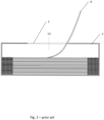
Fig. 3 - Top view of cable box with location of guide device indicated relative to the cable box; -
Fig. 4 - top view of first embodiment of guide device; -
Fig. 5 - Cross-sectional side view of the first embodiment; -
Fig. 6 - Cross-sectional side view of the first embodiment installed in the cable box; -
Fig. 7 - Top view of a second embodiment; -
Fig. 8 - Bottom view of the second embodiment; -
Fig. 9 - Bottom view of a third embodiment; -
Fig. 10 - Bottom view of a fourth embodiment; -
Fig. 11 - Bottom view of a fifth embodiment; -
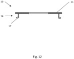
Fig. 12 - Cross-sectional side view of an alternative embodiment of the connector; -
Fig. 13 - Top view of a sixth embodiment of the guide device; -
Fig. 14 - Cross -sectional side view of an embodiment with a guiding surface. - Initially, it is referred to
fig. 1 andfig. 2 . Here it is shown acable box 2 in which acable 8 is rolled up. Thecable box 2 comprises acircular access opening 5 defined with an access opening area A5 and a diameter D5. - Several manufacturers use the same type of cable box. This commonly used cable box is made of cardboard and has a diameter D5 of the circular access opening 5 being 90 mm. A centre of the
access opening 5 is indicated as C5 infigs. 1 and2 . - When an electrician or other user of the cable is starting the installation of the cable, the
access opening 5 is opened tearing away the cardboard piece being present in the access opening 5. The electrician inserts his/her hand into thebox 2 in order to retrieve the end of the cable out from the box. In prior art, the access opening itself serves the purpose of guiding the cable out from the box. - It is now referred to
fig. 4 and 5 , in which a first embodiment of aguide device 10 is shown. Theguide device 10 comprises amain body 11, aconnector 14 provided on themain body 11 and a feed-out opening 15 provided in themain body 11. - The
main body 11 is here a planar and disc-shaped, and will typically be made from a polymer material such as a thermoplastic. A thickness T11 of the disc-shaped body is indicated infig. 5 . The thickness T11 may be 1 - 7 mm, preferably 2 - 4 mm. Themain body 11 is circular, as indicated by anouter perimeter 11P infig. 4 , having a diameter D11 being larger than the diameter D5 of theaccess opening 5. In the present embodiment, the diameter D11 is ca 100 mm. - The
connector 14 is shaped as a tapering, ring-shaped element as shown infig. 4 and fig. 5 . Infig. 4 , the ring-shape of theconnector 14 is indicated as a dashed circle. It should be noted that as long as themain body 11 is not transparent, theconnector 14 is not visible on the top side of themain body 11 shown infig. 4 . Infig. 5 it is shown that the cross section of theconnector 14 forms an apex. Theconnector 14 and themain body 11 will typically be made as one single body, for example manufactured by injection moulding, an additive manufacturing process etc. Alternatively, theconnector 14 and themain body 11 are made as two separate bodies connected to each other, for example by means of fasteners, adhesives etc. - The feed-out
opening 15 is in the present embodiment rectangular, as shown infig. 4 . A centre C15 is indicating the centre of the feed-outopening 15. The centre C5 coincides with a centre C14 indicating the centre of theconnector 14. - The
connector 14 serves the purpose of connecting the guidingdevice 10 to theaccess opening 5. It is now referred tofig. 6 . Here it is shown that theconnector 14 is connected to the access opening 5 by pushing theconnector 14 into theaccess opening 5 until a rear side RS of themain body 11 comes into contact with thebox 2. The tapering shape of theconnector 14 will deform the cardboard material of thebox 2 slightly, causing theconnector 14 to maintain its position relative to theaccess opening 5. A front side FS on the opposite side of the rear side RS is facing away from thebox 2. - As shown in
fig. 3 andfig. 6 , theperimeter 11P of themain body 11 is extending beyond the access opening 5 along the entire circumference of theaccess opening 5. Hence, theaccess opening 5 is only accessible via the feed-outopening 15. - As the
connector 14 is positioned relative to theaccess opening 5, the centre C14 of theconnector 14 is coinciding with the centre C5 of theaccess opening 5. As the centre C15 of the feed-outopening 15 is coinciding with the centre C14 of theconnector 14, the centre C15 of the feed-outopening 15 will also be coinciding with the centre C5 of theaccess opening 5. - As is apparent from
fig. 6 feed-out opening area A15 is smaller than the size of the access opening area A5. Preferably, the feed-out opening area A15 is 1% to 30% of the access opening area A5. In the present embodiment, the rectangular feed-outopening 15 has a dimension of 45.0 mm x 35.3 mm, i.e. an area of 15.89 cm2, while the access opening area A5 is π x 45 mm x 45 mm, i.e. 63.6 cm2. Hence, the feed-out opening area A15 is here ca 25% of the access opening area A5. - It is now referred to
fig. 7 and 8 . It should be noted that many features of this embodiment are similar to the above embodiments, and only differences will be described in detail here. - In
figs. 7 and 8 it is shown that themain body 11 is shaped as a square, and that the feed-outopening 15 is rectangular withrounded corners 15c. - It is now referred to
fig. 9 . It should be noted that many features of this embodiment are similar to the above embodiments, and only differences will be described in detail here. - As in the first embodiment, the
main body 11 is circular. Infig. 9 it is apparent that the feed-outopening 15 is oval or elliptical. - It is now referred to
fig. 10 . It should be noted that many features of this embodiment are similar to the above embodiments, and only differences will be described in detail here. - As in the first embodiment, the
main body 11 is circular. Infig. 10 it is apparent that the feed-outopening 15 is circular and defined with a diameter D15. In the present embodiment, the diameter D15 is ca 30 mm, resulting in an area of π x 15 mm x 15 mm, i.e. 7.0 cm2, which corresponds to 11.1% of the access opening area. - It is now referred to
fig. 11 . It should be noted that many features of this embodiment are similar to the above embodiments, and only differences will be described in detail here. - As in the first embodiment, the
main body 11 is circular and the feed-outopening 15 is rectangular. Infig. 11 it is apparent that theconnector 14 does not form a full circle. Instead, theconnector 14 comprises four connector segments 14s1, 14s2, 14s3, 14sf spaced apart from each other as indicated by distances D14s1, D14s2, D14s3, D14sf. It is apparent that each connector segment forms a circle section and that the connector segments in total have a shape enabling them to be connected to theaccess opening 5. - It is now referred to
fig. 13 . It should be noted that many features of this embodiment are similar to the above embodiments, and only differences will be described in detail here. - Here, it is shown that the
main body 11 comprises fourflaps 11F extending beyond theaccess opening 5, while other parts of themain body 11 do not extend beyond theaccess opening 5. Theconnector 14 will here be provided on the rear side of theflaps 11F. - This embodiment has a circular feed-out
opening 15 similar tofig. 10 . - Some further embodiments will now be described. These further embodiments may be combined with the above embodiments.
- It is now referred to
fig. 12 . Here, theconnector 14 comprises onecontinuous locking element 17 or several spaced apart lockingelements 17. The lockingelement 17 is shown to form a catch which locks to the inside of thebox 2 near theaccess opening 15. Hence, the risk of accidental release of the guidingdevice 10 from the access opening 5 may be reduced. The lockingelement 17 may be a type of snap-on locking element. - It is now referred to
fig. 14 . Here, the feed-outopening 15 is provided with a guidingsurface 18 for guiding thecable 8 out from thecable box 2. The guidingsurface 18 is here funnel-shaped. - Extensive tests have shown that a smaller feed-out diameter reduces tangling significantly. These tests also shown that is advantageous if the cable is fed out from the centre of the access opening 5 of the
cable box 2, i.e. that the centre C15 of the feed-outopening 15 is coinciding with the centre C14 of theconnector 14. -
- 2 - cable box
- 5 - access opening
- 8 - cable
- 10 - guide device
- 11 - main body
- 11P - outer perimeter
- 14 - connector
- 14s1 - first segment
- 14s2 - second segment
- 14s3 - third segment
- 14sf- further segment
- 15 - feed-out opening
- 15L - longest side
- 15S - shortest side
- 15f - first side
- 15s - second side
- 17 - locking device
- 18 - guide surface
- A1 - axis
- A15 - feed-out opening area
- A5 - access opening area
- C15 - centre
- C5 - centre
- D14s1 - first segment distance
- D14s2 - second segment distance
- D14s3 - third segment distance
- D14sf - further segment distance
- D5 - diameter
Claims (15)
- A guide device (10) for guiding a cable (8) out from a cable box (2) having an access opening (5) defined with an access opening area (A5); wherein the guide device (10) comprises:- a main body (11) with an outer perimeter (11P);- a connector (14) provided on the main body (11) and connectable to the access opening (5);- a feed-out opening (15) provided in the main body (11) for guiding a cable (8) stored within the cable box (2) out from the cable box (2);wherein the feed-out opening (15) has a feed-out opening area (A15);wherein the feed-out opening area (A15) is smaller than the access opening area (A5);wherein at least a part of the outer perimeter (11P) of the main body (11) is extending beyond the access opening (5).
- The guide device (10) according to claim 1, wherein a centre (C14) of the connector (14) is aligned with a centre (C15) of the feed-out opening (15).
- The guide device (10) according to any one of the previous claims, wherein the feed-out opening (15) has a rectangular shape.
- The guide device (10) according to claim 1 or 2, wherein the feed-out opening (15) has a circular shape or an elliptical shape.
- The guide device (10) according to any one of the previous claims, wherein the feed-out opening area (A15) is 1% to 30% of the access opening area (A5).
- The guide device (10) according to any one of the previous claims, wherein the main body (11) is disc-shaped.
- The guide device (10) according to claim 6, wherein the disc-shaped main body (11) is planar.
- The guide device (10) according to any one of the previous claims, wherein the main body (11) is circular having a diameter (D11) larger than a diameter (D5) of the access opening (5).
- The guide device (10) according to any one of the previous claims, wherein the connector (14) is connectable to the access opening (5) by pushing the connector (14) into the access opening (5).
- The guide device (10) according to any one of the previous claims, wherein the connector (14) is circular.
- The guide device (10) according to any one of claims 1-9, wherein the connector (14) comprises at least three connector segments (14s1, 14s2, 14s3, 14sf).
- The guide device (10) according to claim 11, wherein the at least three connector segments (14s1, 14s2, 14s3, 14sf) are spaced apart from each other.
- The guide device (10) according to any one of the previous claims, wherein the connector (14) comprises a locking device (17).
- The guide device (10) according to claims 11 and 13, wherein at least some of the at least three connector segments (14s1, 14s2, 14s3, 14sf) comprise a locking device (17).
- The guide device (10) according to any one of the previous claims, wherein the feed-out opening (15) is provided with a guiding surface (18) for guiding the cable (8) out from the cable box (2).
Priority Applications (1)
| Application Number | Priority Date | Filing Date | Title |
|---|---|---|---|
| EP22307028.5A EP4391258A1 (en) | 2022-12-23 | 2022-12-23 | A guide device for cable boxes |
Applications Claiming Priority (1)
| Application Number | Priority Date | Filing Date | Title |
|---|---|---|---|
| EP22307028.5A EP4391258A1 (en) | 2022-12-23 | 2022-12-23 | A guide device for cable boxes |
Publications (1)
| Publication Number | Publication Date |
|---|---|
| EP4391258A1 true EP4391258A1 (en) | 2024-06-26 |
Family
ID=85017844
Family Applications (1)
| Application Number | Title | Priority Date | Filing Date |
|---|---|---|---|
| EP22307028.5A Withdrawn EP4391258A1 (en) | 2022-12-23 | 2022-12-23 | A guide device for cable boxes |
Country Status (1)
| Country | Link |
|---|---|
| EP (1) | EP4391258A1 (en) |
Citations (3)
| Publication number | Priority date | Publication date | Assignee | Title |
|---|---|---|---|---|
| US20040026284A1 (en) * | 2002-08-05 | 2004-02-12 | Nordx/Cdt, Inc. | Box for payout of a filamentary product |
| US7156334B1 (en) * | 2002-03-01 | 2007-01-02 | X-Spooler, Inc. | Pay-out tube |
| US20160101962A1 (en) * | 2014-10-14 | 2016-04-14 | Reelex Packaging Solutions, Inc. | Locking Ring and Packaging for Dispensing Wound Material From a Container |
-
2022
- 2022-12-23 EP EP22307028.5A patent/EP4391258A1/en not_active Withdrawn
Patent Citations (3)
| Publication number | Priority date | Publication date | Assignee | Title |
|---|---|---|---|---|
| US7156334B1 (en) * | 2002-03-01 | 2007-01-02 | X-Spooler, Inc. | Pay-out tube |
| US20040026284A1 (en) * | 2002-08-05 | 2004-02-12 | Nordx/Cdt, Inc. | Box for payout of a filamentary product |
| US20160101962A1 (en) * | 2014-10-14 | 2016-04-14 | Reelex Packaging Solutions, Inc. | Locking Ring and Packaging for Dispensing Wound Material From a Container |
Non-Patent Citations (1)
| Title |
|---|
| ANONYMOUS: "Amazon.com: Yinpecly 2pcs Metal Desk Grommet for Wire Organizer Fits 3.15"/80mm Hole Cable Grommet Desk Hole Cover Bronze for Office Computer Table Wire Cord Cable Managing&Hiding : Industrial & Scientific", 9 March 2021 (2021-03-09), XP093051832, Retrieved from the Internet <URL:https://www.amazon.com/dp/B08YDN7M4G/ref=sspa_dk_detail_5?pf_rd_p=0d1092dc-81bb-493f-8769-d5c802257e94&pf_rd_r=KWKP5PRHE7C9R04SWN6M&pd_rd_wg=e3bpX&pd_rd_w=nvufe&content-id=amzn1.sym.0d1092dc-81bb-493f-8769-d5c802257e94&pd_rd_r=1ea94ca5-8257-4e60-bf11-bb876d0436f7&s=hi&sp_csd=d2lkZ2V0TmFtZT1zcF9kZXRh> [retrieved on 20230605] * |
Similar Documents
| Publication | Publication Date | Title |
|---|---|---|
| US9762042B2 (en) | Cable connector and electrical box | |
| US7824213B1 (en) | One-piece electrical cable connector having a retaining spring | |
| US8106297B1 (en) | Grounded conduit bushing | |
| US4919370A (en) | Cable fitting | |
| US5374017A (en) | Cable fitting | |
| US4132665A (en) | Wire feed funnel | |
| US5236177A (en) | Electrical junction box wire pulling guide | |
| US9425596B2 (en) | Wire connector | |
| US20090117775A1 (en) | Wire retention connector system | |
| US6177633B1 (en) | Cable connector | |
| US8415571B2 (en) | Slotted retainer ring for snap-in electrical connector | |
| US4171123A (en) | Conductor pulling device | |
| JP2004525399A (en) | Cable guiding device for guiding cables through holes in panel | |
| US20140262416A1 (en) | Electrical Box | |
| CA2696452C (en) | Electrical junction box | |
| US7897871B1 (en) | Junction box with integrated connectors for electrical wiring | |
| US6247235B1 (en) | Sheathing slitter and cutter tool | |
| US7880087B2 (en) | Toneable conduit with loose toning signal wire | |
| US9865972B2 (en) | Electrical connector with spring clip | |
| US7178226B2 (en) | Wire installation tool | |
| US3006661A (en) | Cable clamp for connecting boxes | |
| US6736715B2 (en) | Electrical junction assembly and related splicing method | |
| US9122034B2 (en) | Cable slack storage for wall outlet | |
| US10950371B2 (en) | Nonmetallic push-in connector | |
| US11264783B2 (en) | Headlock cable installation system |
Legal Events
| Date | Code | Title | Description |
|---|---|---|---|
| PUAI | Public reference made under article 153(3) epc to a published international application that has entered the european phase |
Free format text: ORIGINAL CODE: 0009012 |
|
| STAA | Information on the status of an ep patent application or granted ep patent |
Free format text: STATUS: THE APPLICATION HAS BEEN PUBLISHED |
|
| AK | Designated contracting states |
Kind code of ref document: A1 Designated state(s): AL AT BE BG CH CY CZ DE DK EE ES FI FR GB GR HR HU IE IS IT LI LT LU LV MC ME MK MT NL NO PL PT RO RS SE SI SK SM TR |
|
| STAA | Information on the status of an ep patent application or granted ep patent |
Free format text: STATUS: REQUEST FOR EXAMINATION WAS MADE |
|
| 17P | Request for examination filed |
Effective date: 20250102 |
|
| STAA | Information on the status of an ep patent application or granted ep patent |
Free format text: STATUS: THE APPLICATION HAS BEEN WITHDRAWN |
|
| 18W | Application withdrawn |
Effective date: 20260407 |