EP4391223A1 - Antenna movable between deployed and partially stowed positions and associated methods - Google Patents
Antenna movable between deployed and partially stowed positions and associated methods Download PDFInfo
- Publication number
- EP4391223A1 EP4391223A1 EP23208721.3A EP23208721A EP4391223A1 EP 4391223 A1 EP4391223 A1 EP 4391223A1 EP 23208721 A EP23208721 A EP 23208721A EP 4391223 A1 EP4391223 A1 EP 4391223A1
- Authority
- EP
- European Patent Office
- Prior art keywords
- antenna
- flexible
- ribs
- support member
- reflector layer
- Prior art date
- Legal status (The legal status is an assumption and is not a legal conclusion. Google has not performed a legal analysis and makes no representation as to the accuracy of the status listed.)
- Granted
Links
Images



Classifications
-
- H—ELECTRICITY
- H01—ELECTRIC ELEMENTS
- H01Q—ANTENNAS, i.e. RADIO AERIALS
- H01Q1/00—Details of, or arrangements associated with, antennas
- H01Q1/27—Adaptation for use in or on movable bodies
- H01Q1/28—Adaptation for use in or on aircraft, missiles, satellites, or balloons
- H01Q1/288—Satellite antennas
-
- H—ELECTRICITY
- H01—ELECTRIC ELEMENTS
- H01Q—ANTENNAS, i.e. RADIO AERIALS
- H01Q15/00—Devices for reflection, refraction, diffraction or polarisation of waves radiated from an antenna, e.g. quasi-optical devices
- H01Q15/14—Reflecting surfaces; Equivalent structures
- H01Q15/16—Reflecting surfaces; Equivalent structures curved in two dimensions [2D], e.g. paraboloidal
- H01Q15/161—Collapsible reflectors
-
- H—ELECTRICITY
- H01—ELECTRIC ELEMENTS
- H01Q—ANTENNAS, i.e. RADIO AERIALS
- H01Q19/00—Combinations of primary active antenna elements and units with secondary devices, e.g. with quasi-optical devices, for giving the antenna a desired directional characteristic
- H01Q19/10—Combinations of primary active antenna elements and units with secondary devices, e.g. with quasi-optical devices, for giving the antenna a desired directional characteristic using reflecting surfaces
- H01Q19/12—Combinations of primary active antenna elements and units with secondary devices, e.g. with quasi-optical devices, for giving the antenna a desired directional characteristic using reflecting surfaces wherein the surfaces are concave
Definitions
- the present invention relates to the field of antennas, and, more particularly, to an antenna having a flexible antenna reflector layer supported by antenna ribs that are movable between deployed and partially stowed positions and related methods.
- the antenna is initially stowed, and when in orbit, the antenna is deployed from its stowed position. To ensure that the antenna is deployed in orbit without snagging and binding, great care is taken when initially stowing the antenna.
- These antennas usually include cords and ties that interconnect the flexible antenna reflector layer to the rigid antenna ribs and ensure that when the antenna is deployed, the proper antenna curvature, such as a parabolic configuration, is maintained.
- the antenna cords and ties are configured to ensure there is no snagging or binding when the antenna is deployed and ensure sufficient tension is imparted to the flexible antenna reflector layer to maintain not only the desired antenna configuration, but also maintain adequate antenna performance.
- an antenna may comprise a plurality of rigid antenna ribs, adjacent antenna ribs being relatively moveable between first and second positions, and a flexible antenna reflector layer.
- a flexible support member may extend behind the flexible antenna reflector layer between adjacent antenna ribs, the flexible support strip having first and second sets of openings therein.
- a drawstring may extend through the first set of openings in the flexible support member between adjacent ribs.
- a rear support cord may be behind the flexible support member between adjacent ribs.
- a plurality of tie cords may end between the flexible antenna reflector layer and the rear support cord and may pass through respective ones of the second set of openings in the flexible support member.
- a biasing member may maintain tension in the drawstring as adjacent antenna ribs move between the first and second positions so that the flexible support member defines a pleated support body for the flexible antenna reflector layer.
- the adjacent antenna ribs may be movable to a fully stowed position.
- the first position may comprise a deployed position and the second position may comprise a partially stowed position.
- the first and second sets of openings may be arranged in an alternating pattern along the flexible support member.
- the flexible support member may comprise a flexible strip.
- the biasing member may comprise a constant force spring, for example.
- the flexible antenna reflector layer may comprise a conductive mesh.
- the plurality of antenna ribs and flexible antenna reflector surface layer may define a parabolic antenna reflector surface.
- An antenna hub may pivotally mount the plurality of antenna ribs.
- An antenna feed may be associated with the flexible antenna reflector layer.
- the plurality of antenna ribs may be configured to be mounted to a space vehicle.
- Another aspect is directed to a method for making an antenna.
- the method includes coupling a flexible support member extending behind a flexible antenna reflector layer between adjacent antenna ribs, the flexible support strip having first and second sets of openings therein and adjacent antenna ribs being relatively moveable between first and second positions.
- the method also includes coupling a drawstring extending through the first set of openings in the flexible support member between adjacent ribs and coupling a plurality of tie cords ending between the flexible antenna reflector layer and a rear support cord and passing through respective ones of the second set of openings in the flexible support member.
- the method also includes coupling a biasing member for maintaining tension in the drawstring as adjacent antenna ribs move between the first and second positions so that the flexible support member defines a pleated support body for the flexible antenna reflector layer.
- an antenna is illustrated generally at 20 and includes a plurality of rigid antenna ribs 22 configured to be mounted to a rigid structure, bus, and/or space vehicle 24, and in this example, a satellite as illustrated by the dashed configuration in FIG. 1 .
- Adjacent antenna ribs 22 are movable to a fully stowed position, such as when the space vehicle 24 as a satellite is launched into orbit.
- Adjacent antenna ribs 22 are also relatively movable between first and second positions, such as the first position corresponding to a deployed position 30 ( FIGS. 1 , 2 and 6 ), and a second position as a partially stowed position 32 ( FIGS. 3 and 4 ).
- an antenna hub 34 pivotally mounts the plurality of rigid antenna ribs 22 and may be an integral part of or mounted to the space vehicle, such as the illustrated satellite 24.
- a flexible antenna reflector layer 38 such as formed from a conductive mesh, is carried by the rigid antenna ribs 22, and in this example shown in FIGS. 2 and 6 , defines a parabolic antenna reflector surface as shown by the parabolic curvature in those sectional views.
- the dashed line referenced at 38 defines a cut section of the flexible antenna reflector layer, which normally covers the entire surface area defined between the rigid antenna ribs 22.
- An antenna feed 40 as shown in FIG. 1 may be associated with the flexible antenna reflector layer 38 and include associated cabling or other interconnects that may interface to a transmitter or receiver carried by the space vehicle 24.
- a flexible support member 42 formed as a flexible strip may extend behind the flexible antenna reflector layer 38 between adjacent antenna ribs 22 as best shown in FIGS. 2-4 and the side elevation image of FIG. 6 , and include first and second sets of openings 44,46 therein ( FIG. 2 ).
- a drawstring 50 extends through the first set of openings 44 in the flexible support member 42 between adjacent antenna ribs 22 and a rear support cord 52 is behind the flexible support member 42 between adjacent antenna ribs.
- nine (9) parallel drawstrings 50 extend between the illustrated antenna ribs 22, and each drawstring includes an associated flexible strip 42. It should be understood that this number is dependent on many factors and may change based on additional development.
- a much larger number of rear support cords 52 extend between the antenna ribs 22 as shown in FIG. 1 .
- a plurality of tie cords 54 extend and end between the flexible antenna reflector layer 38 and the rear support cord 52 and pass through respective ones of the second set of openings 46 in the flexible support member 42 ( FIG. 2 ).
- a biasing member 58 such as a constant force spring, maintains tension in the drawstring 50 as adjacent antenna ribs 22 move between the first and second positions 30,32 so that the flexible support member 42 defines a pleated support body for the flexible antenna reflector layer 38.
- the first and second sets of openings 44,46 are arranged in an alternating pattern along the flexible support member 42, which in this example is formed as a flexible strip. These openings 44,46 may be different in length (separation) from each other depending on the amplitudes of the flexible support member 42 and geometries of the rear support cords 52.
- the flexible antenna reflector layer 38 (the conductive mesh) is pleated by the flexible strip 42 as the adjacent antenna ribs 22 are moved into the second position 32 corresponding to the partially stowed position as shown in FIGS. 3 and 4 .
- the flexible strips 42 create a series of parabolic curve sections that are constrained by the existing rear support cords 52 and plurality of tie cords 54 that extend and end between the flexible antenna reflector layer 38 and the rear support cords to assist in managing the rear support cords, tie cords, and flexible antenna reflector layer during stow and deploy operations.
- the flexible strip 42 may introduce a new parabolic shape.
- the flexible strip 42 may be formed of a material to impart the parabolic shape and have some material memory.
- the flexible strip 42 also may have different amplitudes between the crest and trough and may be dependent upon the distance between the flexible antenna reflector layer as the conductive mesh 38 and the rear support cords 52.
- the flexible support member 42 in the example of FIG. 2 is shown in one configuration based upon one rear support cord 52 geometry. However, the amplitudes of the flexible support member 42 may increase or decrease depending on the curvature of the rear support cords 52.
- Each drawstring 50 is held constantly taut by its biasing member 58 that maintains tension in the drawstring as adjacent antenna ribs 22 move between the first and second positions 30,32 so that the flexible support member 42 defines a pleated support body for the flexible antenna reflector layer 38.
- the drawstring 50 extends through the first set of openings 44 in the flexible support member 42 between adjacent antenna ribs 22.
- the drawstring 50 cooperates with the plurality of tie cords 54 that extend and end between the flexible antenna reflector layer 38 and rear support cord 52 and passes through respective ones of the second set of openings 46 in the flexible support member 42.
- the distance between where the drawstring 50 enters and exits the flexible strip 42 develops a unique "pleating" result that occurs naturally to match the excess length of the rear support cord 52 and flexible antenna reflector layer 38 as a conductive mesh that is managed during partial stowing of the antenna 20 in orbit.
- rear support cords 52 are spaced along the adjacent antenna ribs 22.
- the drawstrings 50 and flexible support members 42 as the flexible strips are placed in this example between about every fourth to sixth rear support cord 52 depending on the configuration of the antenna 20 and how much control the rear support cords 52 and flexible antenna reflector layer 38 require in management during the stowing and deployment operation.
- the length of the flexible strip 42, the number of periods, amplitudes, and tie cord 54 spacing ( FIG. 2 ) is dependent upon the distance between the adjacent antenna ribs 22 and the number of rear support cords 52 and the shape of the antenna 20.
- the drawstring 50 constrains the flexible strip 42 along a single axis to prevent buckling, twisting and/or snagging during stowing and deployment operations of the antenna 20.
- the biasing member 58 may be formed as a constant force spring and maintains the tension in the drawstring 50 as adjacent antenna ribs 22 move between the first and second positions 30,32 so that the flexible support member as the flexible strip 42 defines a pleated support body for the flexible antenna reflector layer 38.
- a biasing member housing 60 supports a spool 62 with the drawstring 50 wrapped around the spool and contained within the biasing member housing.
- the spool 62 is carried by a support shaft 64 and a constant force spring 66 has one end attached to the support shaft 64, and the other end attached to the spool 62 to maintain constant tension on the drawstring 50.
- the biasing member 58 formed with the constant force spring 66 may be configured as a 1:1 system where the length of the constant force spring is equal to the length of the drawstring 50 to be stored.
- Each drawstring 50 includes an associated biasing member 58 connected to the drawstring 50 ( FIG. 1 ).
- nine biasing members 58 are connected to the nine drawstrings 50.
- a geared spring real that incorporates a shaft and a constant force spring 66 that is attached to a gear contained within a housing and a spool carried by another shaft.
- the drawstring 50 is wrapped around the spool carried by the second shaft.
- This second type of system could be a 3:1 system where the length of a constant force spring 66 is one-third of the length of the drawstring 50 to be stored.
- This differentiator is important because due to weight constraints or physical properties of the constant force spring 66, the overall length may be limited in size and may not be able to extend all the way across the panel defined by the flexible antenna reflector layer 38 to the other adjacent antenna rib 22 towards the outboard portions of the flexible antenna reflector layer.
- the antenna 20 achieves a "hands-off,” in orbit stow and deploy process.
- the flexible antenna reflector layer as a conductive mesh 38 in an example may be pleated successfully without tangling, and the rear support cords 52 and tie cords 54 successfully managed not only during stowing of as much as 70%-90% of the antenna 20, but also during a redeployment cycle.
- This configuration allows the antenna 20 to be more resilient in operation during specific mission scenarios and overcomes the technical drawbacks with current deployable conductive mesh and reflector antenna technologies.
- the antenna 20 also minimizes and alleviates the requirement for adaptation of numerous types of stowage devices to organize and stow the various components of the antenna, including the flexible antenna reflector layer as the example conductive mesh 38. Different manufacturing techniques may be used and an example is shown in the high-level flowchart of FIG. 7 . A method for making the antenna 20 is illustrated generally at 100.
- the process starts (Block 102 ) and the flexible support member 42 as the flexible strip that extends behind a flexible antenna reflector layer 38 is coupled between adjacent antenna ribs 22.
- This flexible strip 42 has first and second sets of openings 44,46 and adjacent antenna ribs 22 are relatively movable between first and second positions 30,32 (Block 104 ).
- the drawstring 50 that extends through the first set of openings 44 in the flexible support member 42 is coupled between adjacent antenna ribs 22 (Block 106 ).
- the method also includes coupling a plurality of tie cords 54 ending between the flexible antenna reflector layer 38 and the rear support cord 52 and passing through respective ones of the second set of openings 46 (Block 108 ).
- the process further includes coupling a biasing member 58 for maintaining tension in the drawstring 50 as adjacent antenna ribs 22 move between the first and second positions 30,32 so that the flexible support member 42 defines a pleated support body for the flexible antenna reflector layer 38 (Block 110 ).
- the process ends (Block 112 ).
Landscapes
- Physics & Mathematics (AREA)
- Engineering & Computer Science (AREA)
- Astronomy & Astrophysics (AREA)
- General Physics & Mathematics (AREA)
- Remote Sensing (AREA)
- Aviation & Aerospace Engineering (AREA)
- Electromagnetism (AREA)
- Aerials With Secondary Devices (AREA)
- Details Of Aerials (AREA)
Abstract
Description
- The present invention relates to the field of antennas, and, more particularly, to an antenna having a flexible antenna reflector layer supported by antenna ribs that are movable between deployed and partially stowed positions and related methods.
- An antenna that is configured to be mounted to a space vehicle, such as a satellite, usually includes a number of antenna ribs that support a flexible antenna reflector layer, such as a conductive mesh. The antenna is initially stowed, and when in orbit, the antenna is deployed from its stowed position. To ensure that the antenna is deployed in orbit without snagging and binding, great care is taken when initially stowing the antenna. These antennas usually include cords and ties that interconnect the flexible antenna reflector layer to the rigid antenna ribs and ensure that when the antenna is deployed, the proper antenna curvature, such as a parabolic configuration, is maintained. The antenna cords and ties are configured to ensure there is no snagging or binding when the antenna is deployed and ensure sufficient tension is imparted to the flexible antenna reflector layer to maintain not only the desired antenna configuration, but also maintain adequate antenna performance.
- Many of these antenna unfortunately are not configured for stowing in orbit. Even a partial, in-orbit stow increases the chances that the antenna ties, cords, or reflector layer may entangle during redeployment. For example, if the antenna is partially stowed in orbit, and then redeployed, often one or more of the cords, ties or flexible antenna reflector layer may bind or "snag," making redeployment challenging. Even after redeployment, if only a small segment of the flexible antenna reflector layer is folded or snagged, that segment can create undesirable antenna performance, and may sometimes even render the antenna inoperable. There are therefore advantages in configuring an antenna that may be fully deployed, and later partially or fully stowed in orbit, and then successfully deployed again without bunching, entangling or snagging the ties, cords or flexible antenna reflector layer.
- In general, an antenna may comprise a plurality of rigid antenna ribs, adjacent antenna ribs being relatively moveable between first and second positions, and a flexible antenna reflector layer. A flexible support member may extend behind the flexible antenna reflector layer between adjacent antenna ribs, the flexible support strip having first and second sets of openings therein. A drawstring may extend through the first set of openings in the flexible support member between adjacent ribs. A rear support cord may be behind the flexible support member between adjacent ribs. A plurality of tie cords may end between the flexible antenna reflector layer and the rear support cord and may pass through respective ones of the second set of openings in the flexible support member. A biasing member may maintain tension in the drawstring as adjacent antenna ribs move between the first and second positions so that the flexible support member defines a pleated support body for the flexible antenna reflector layer.
- The adjacent antenna ribs may be movable to a fully stowed position. The first position may comprise a deployed position and the second position may comprise a partially stowed position. The first and second sets of openings may be arranged in an alternating pattern along the flexible support member. The flexible support member may comprise a flexible strip. The biasing member may comprise a constant force spring, for example.
- The flexible antenna reflector layer may comprise a conductive mesh. The plurality of antenna ribs and flexible antenna reflector surface layer may define a parabolic antenna reflector surface. An antenna hub may pivotally mount the plurality of antenna ribs. An antenna feed may be associated with the flexible antenna reflector layer. The plurality of antenna ribs may be configured to be mounted to a space vehicle.
- Another aspect is directed to a method for making an antenna. The method includes coupling a flexible support member extending behind a flexible antenna reflector layer between adjacent antenna ribs, the flexible support strip having first and second sets of openings therein and adjacent antenna ribs being relatively moveable between first and second positions. The method also includes coupling a drawstring extending through the first set of openings in the flexible support member between adjacent ribs and coupling a plurality of tie cords ending between the flexible antenna reflector layer and a rear support cord and passing through respective ones of the second set of openings in the flexible support member.
- The method also includes coupling a biasing member for maintaining tension in the drawstring as adjacent antenna ribs move between the first and second positions so that the flexible support member defines a pleated support body for the flexible antenna reflector layer.
- Other objects, features and advantages of the present embodiments will become apparent from the detailed description which follows, when considered in light of the accompanying drawings in which:
-
FIG. 1 is a partial plan view of the antenna in a deployed position showing the rigid antenna ribs, drawstring, flexible support member, and flexible antenna reflector layer. -
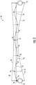
FIG. 2 is a partial schematic, sectional view of the antenna showing two adjacent ribs in their deployed position. -
FIG. 3 is another schematic, sectional view of the antenna ofFIG. 2 in an about 30% stowed position. -
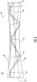
FIG. 4 is another schematic, sectional view of the antenna ofFIG. 2 in an about 70% stowed position. -
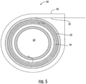
FIG. 5 is a schematic diagram of an example biasing member using a constant force spring. -
FIG. 6 is a partial side elevation image of the antenna showing two adjacent ribs in their deployed position. -
FIG. 7 is a high-level flowchart of a method for making the antenna ofFIG. 1 . - The present description is made with reference to the accompanying drawings, in which exemplary embodiments are shown. However, many different embodiments may be used, and thus, the description should not be construed as limited to the particular embodiments set forth herein. Rather, these embodiments are provided so that this disclosure will be thorough and complete. Like numbers refer to like elements throughout.
- Referring now to
FIGS. 1 and2 , an antenna is illustrated generally at 20 and includes a plurality ofrigid antenna ribs 22 configured to be mounted to a rigid structure, bus, and/orspace vehicle 24, and in this example, a satellite as illustrated by the dashed configuration inFIG. 1 .Adjacent antenna ribs 22 are movable to a fully stowed position, such as when thespace vehicle 24 as a satellite is launched into orbit.Adjacent antenna ribs 22 are also relatively movable between first and second positions, such as the first position corresponding to a deployed position 30 (FIGS. 1 ,2 and6 ), and a second position as a partially stowed position 32 (FIGS. 3 and 4 ). In this example, anantenna hub 34 pivotally mounts the plurality ofrigid antenna ribs 22 and may be an integral part of or mounted to the space vehicle, such as the illustratedsatellite 24. - A flexible
antenna reflector layer 38, such as formed from a conductive mesh, is carried by therigid antenna ribs 22, and in this example shown inFIGS. 2 and6 , defines a parabolic antenna reflector surface as shown by the parabolic curvature in those sectional views. InFIG. 1 , the dashed line referenced at 38 defines a cut section of the flexible antenna reflector layer, which normally covers the entire surface area defined between therigid antenna ribs 22. An antenna feed 40 as shown inFIG. 1 may be associated with the flexibleantenna reflector layer 38 and include associated cabling or other interconnects that may interface to a transmitter or receiver carried by thespace vehicle 24. - A
flexible support member 42 formed as a flexible strip may extend behind the flexibleantenna reflector layer 38 betweenadjacent antenna ribs 22 as best shown inFIGS. 2-4 and the side elevation image ofFIG. 6 , and include first and second sets ofopenings FIG. 2 ). Adrawstring 50 extends through the first set ofopenings 44 in theflexible support member 42 betweenadjacent antenna ribs 22 and arear support cord 52 is behind theflexible support member 42 between adjacent antenna ribs. In the example shown inFIG. 1 , nine (9)parallel drawstrings 50 extend between the illustratedantenna ribs 22, and each drawstring includes an associatedflexible strip 42. It should be understood that this number is dependent on many factors and may change based on additional development. A much larger number ofrear support cords 52 extend between theantenna ribs 22 as shown inFIG. 1 . - A plurality of
tie cords 54 extend and end between the flexibleantenna reflector layer 38 and therear support cord 52 and pass through respective ones of the second set ofopenings 46 in the flexible support member 42 (FIG. 2 ). Abiasing member 58, such as a constant force spring, maintains tension in thedrawstring 50 asadjacent antenna ribs 22 move between the first andsecond positions flexible support member 42 defines a pleated support body for the flexibleantenna reflector layer 38. In an example, the first and second sets ofopenings flexible support member 42, which in this example is formed as a flexible strip. Theseopenings flexible support member 42 and geometries of therear support cords 52. - The flexible antenna reflector layer 38 (the conductive mesh) is pleated by the
flexible strip 42 as theadjacent antenna ribs 22 are moved into thesecond position 32 corresponding to the partially stowed position as shown inFIGS. 3 and 4 . The flexible strips 42 create a series of parabolic curve sections that are constrained by the existingrear support cords 52 and plurality oftie cords 54 that extend and end between the flexibleantenna reflector layer 38 and the rear support cords to assist in managing the rear support cords, tie cords, and flexible antenna reflector layer during stow and deploy operations. - The kinematic movement of the
rigid antenna ribs 22 while stowing in orbit may disrupt the curvature and tension of the flexibleantenna reflector layer 38. Theflexible strip 42 may introduce a new parabolic shape. Theflexible strip 42 may be formed of a material to impart the parabolic shape and have some material memory. Theflexible strip 42 also may have different amplitudes between the crest and trough and may be dependent upon the distance between the flexible antenna reflector layer as theconductive mesh 38 and therear support cords 52. Theflexible support member 42 in the example ofFIG. 2 is shown in one configuration based upon onerear support cord 52 geometry. However, the amplitudes of theflexible support member 42 may increase or decrease depending on the curvature of therear support cords 52. Eachdrawstring 50 is held constantly taut by its biasingmember 58 that maintains tension in the drawstring asadjacent antenna ribs 22 move between the first andsecond positions flexible support member 42 defines a pleated support body for the flexibleantenna reflector layer 38. - The
drawstring 50 extends through the first set ofopenings 44 in theflexible support member 42 betweenadjacent antenna ribs 22. Thedrawstring 50 cooperates with the plurality oftie cords 54 that extend and end between the flexibleantenna reflector layer 38 andrear support cord 52 and passes through respective ones of the second set ofopenings 46 in theflexible support member 42. As thedrawstring 50 is held constantly taut by the biasingmember 58, the distance between where thedrawstring 50 enters and exits theflexible strip 42 develops a unique "pleating" result that occurs naturally to match the excess length of therear support cord 52 and flexibleantenna reflector layer 38 as a conductive mesh that is managed during partial stowing of theantenna 20 in orbit. - In the example of the
antenna 20 shown inFIG. 1 ,rear support cords 52 are spaced along theadjacent antenna ribs 22. Thedrawstrings 50 andflexible support members 42 as the flexible strips are placed in this example between about every fourth to sixthrear support cord 52 depending on the configuration of theantenna 20 and how much control therear support cords 52 and flexibleantenna reflector layer 38 require in management during the stowing and deployment operation. - The length of the
flexible strip 42, the number of periods, amplitudes, andtie cord 54 spacing (FIG. 2 ) is dependent upon the distance between theadjacent antenna ribs 22 and the number ofrear support cords 52 and the shape of theantenna 20. Thedrawstring 50 constrains theflexible strip 42 along a single axis to prevent buckling, twisting and/or snagging during stowing and deployment operations of theantenna 20. - As noted before, the biasing
member 58 may be formed as a constant force spring and maintains the tension in thedrawstring 50 asadjacent antenna ribs 22 move between the first andsecond positions flexible strip 42 defines a pleated support body for the flexibleantenna reflector layer 38. In the example of the schematic diagram of the biasingmember 58 ofFIG. 5 , a biasingmember housing 60 supports aspool 62 with thedrawstring 50 wrapped around the spool and contained within the biasing member housing. Thespool 62 is carried by asupport shaft 64 and aconstant force spring 66 has one end attached to thesupport shaft 64, and the other end attached to thespool 62 to maintain constant tension on thedrawstring 50. In this example, the biasingmember 58 formed with theconstant force spring 66 may be configured as a 1:1 system where the length of the constant force spring is equal to the length of thedrawstring 50 to be stored. - Each
drawstring 50 includes an associated biasingmember 58 connected to the drawstring 50 (FIG. 1 ). In the example ofFIG. 1 , nine biasingmembers 58 are connected to the ninedrawstrings 50. Although not illustrated, it is also possible to use a geared spring real that incorporates a shaft and aconstant force spring 66 that is attached to a gear contained within a housing and a spool carried by another shaft. Thedrawstring 50 is wrapped around the spool carried by the second shaft. This second type of system could be a 3:1 system where the length of aconstant force spring 66 is one-third of the length of thedrawstring 50 to be stored. This differentiator is important because due to weight constraints or physical properties of theconstant force spring 66, the overall length may be limited in size and may not be able to extend all the way across the panel defined by the flexibleantenna reflector layer 38 to the otheradjacent antenna rib 22 towards the outboard portions of the flexible antenna reflector layer. - The
antenna 20 achieves a "hands-off," in orbit stow and deploy process. The flexible antenna reflector layer as aconductive mesh 38 in an example may be pleated successfully without tangling, and therear support cords 52 andtie cords 54 successfully managed not only during stowing of as much as 70%-90% of theantenna 20, but also during a redeployment cycle. This configuration allows theantenna 20 to be more resilient in operation during specific mission scenarios and overcomes the technical drawbacks with current deployable conductive mesh and reflector antenna technologies. - The
antenna 20 also minimizes and alleviates the requirement for adaptation of numerous types of stowage devices to organize and stow the various components of the antenna, including the flexible antenna reflector layer as the exampleconductive mesh 38. Different manufacturing techniques may be used and an example is shown in the high-level flowchart ofFIG. 7 . A method for making theantenna 20 is illustrated generally at 100. - The process starts (Block 102) and the
flexible support member 42 as the flexible strip that extends behind a flexibleantenna reflector layer 38 is coupled betweenadjacent antenna ribs 22. Thisflexible strip 42 has first and second sets ofopenings adjacent antenna ribs 22 are relatively movable between first andsecond positions 30,32 (Block 104). Thedrawstring 50 that extends through the first set ofopenings 44 in theflexible support member 42 is coupled between adjacent antenna ribs 22 (Block 106). The method also includes coupling a plurality oftie cords 54 ending between the flexibleantenna reflector layer 38 and therear support cord 52 and passing through respective ones of the second set of openings 46 (Block 108). The process further includes coupling a biasingmember 58 for maintaining tension in thedrawstring 50 asadjacent antenna ribs 22 move between the first andsecond positions flexible support member 42 defines a pleated support body for the flexible antenna reflector layer 38 (Block 110). The process ends (Block 112). - Many modifications and other embodiments of the invention will come to the mind of one skilled in the art having the benefit of the teachings presented in the foregoing descriptions and the associated drawings. Therefore, it is understood that the invention is not to be limited to the specific embodiments disclosed, and that modifications and embodiments are intended to be included within the scope of the appended claims.
Claims (10)
- An antenna comprising:a plurality of rigid antenna ribs, adjacent antenna ribs being relatively moveable between first and second positions;a flexible antenna reflector layer;a flexible support member extending behind the flexible antenna reflector layer between adjacent antenna ribs, the flexible support member having first and second sets of openings therein;a drawstring extending through the first set of openings in the flexible support member between adjacent ribs;a rear support cord behind the flexible support member between adjacent ribs;a plurality of tie cords ending between the flexible antenna reflector layer and the rear support cord and passing through respective ones of the second set of openings in the flexible support member; anda biasing member for maintaining tension in the drawstring as adjacent antenna ribs move between the first and second positions so that the flexible support member defines a pleated support body for the flexible antenna reflector layer.
- The antenna of claim 1 wherein the adjacent antenna ribs are movable to a fully stowed position; and wherein the first position comprises a deployed position and the second position comprises a partially stowed position.
- The antenna of claim 1 wherein the first and second sets of openings are arranged in an alternating pattern along the flexible support member.
- The antenna of claim 1 wherein the flexible support member comprises a flexible strip.
- The antenna of claim 1 wherein the biasing member comprises a constant force spring.
- The antenna of claim 1 wherein the flexible antenna reflector layer comprises a conductive mesh.
- A method for making an antenna comprising:coupling a flexible support member extending behind a flexible antenna reflector layer between adjacent antenna ribs, the flexible support member having first and second sets of openings therein and adjacent antenna ribs being relatively moveable between first and second positions;coupling a drawstring extending through the first set of openings in the flexible support member between adjacent ribs;coupling a plurality of tie cords ending between the flexible antenna reflector layer and a rear support cord and passing through respective ones of the second set of openings in the flexible support member; andcoupling a biasing member for maintaining tension in the drawstring as adjacent antenna ribs move between the first and second positions so that the flexible support member defines a pleated support body for the flexible antenna reflector layer.
- The method of claim 7 wherein the first and second sets of openings are arranged in an alternating pattern along the flexible support member.
- The method of claim 7 wherein the flexible support member comprises a flexible strip.
- The method of claim 7 wherein the biasing member comprises a constant force spring.
Applications Claiming Priority (1)
| Application Number | Priority Date | Filing Date | Title |
|---|---|---|---|
| US18/068,538 US12027767B1 (en) | 2022-12-20 | 2022-12-20 | Antenna movable between deployed and partially stowed positions and associated methods |
Publications (2)
| Publication Number | Publication Date |
|---|---|
| EP4391223A1 true EP4391223A1 (en) | 2024-06-26 |
| EP4391223B1 EP4391223B1 (en) | 2025-08-06 |
Family
ID=88779233
Family Applications (1)
| Application Number | Title | Priority Date | Filing Date |
|---|---|---|---|
| EP23208721.3A Active EP4391223B1 (en) | 2022-12-20 | 2023-11-09 | Antenna movable between deployed and partially stowed positions and associated methods |
Country Status (2)
| Country | Link |
|---|---|
| US (1) | US12027767B1 (en) |
| EP (1) | EP4391223B1 (en) |
Families Citing this family (1)
| Publication number | Priority date | Publication date | Assignee | Title |
|---|---|---|---|---|
| CN119429178B (en) * | 2024-12-06 | 2025-11-07 | 北京空间飞行器总体设计部 | A scissor-type unfolding mechanism drive device |
Citations (4)
| Publication number | Priority date | Publication date | Assignee | Title |
|---|---|---|---|---|
| US6278416B1 (en) * | 1999-11-18 | 2001-08-21 | Harris Corporation | Surface edge enhancement for space-deployable mesh antenna |
| US20030201949A1 (en) * | 2002-04-29 | 2003-10-30 | Harless Richard I. | Solid surface implementation for deployable reflectors |
| US20190165481A1 (en) * | 2016-06-21 | 2019-05-30 | Institute For Q-Shu Pioneer Of Space Inc. | Expandable antenna |
| US20200153077A1 (en) * | 2018-11-13 | 2020-05-14 | Eagle Technology, Llc | Mesh antenna reflector with deployable perimeter |
Family Cites Families (11)
| Publication number | Priority date | Publication date | Assignee | Title |
|---|---|---|---|---|
| JPS60113503A (en) * | 1983-11-24 | 1985-06-20 | Nippon Telegr & Teleph Corp <Ntt> | Expanding antenna |
| DE3532851A1 (en) * | 1985-09-14 | 1987-04-16 | Messerschmitt Boelkow Blohm | Unfoldable and re-foldable antenna reflector |
| US4845511A (en) * | 1987-01-27 | 1989-07-04 | Harris Corp. | Space deployable domed solar concentrator with foldable panels and hinge therefor |
| US5104211A (en) * | 1987-04-09 | 1992-04-14 | Harris Corp. | Splined radial panel solar concentrator |
| US6219009B1 (en) * | 1997-06-30 | 2001-04-17 | Harris Corporation | Tensioned cord/tie attachment of antenna reflector to inflatable radial truss support structure |
| WO2001054228A1 (en) * | 2000-01-18 | 2001-07-26 | Medzmariashvili Elgudja V | Expandable parabolic antenna |
| US6353421B1 (en) * | 2000-09-14 | 2002-03-05 | Ball Aerospace And Technologies Corp. | Deployment of an ellectronically scanned reflector |
| WO2005027186A2 (en) * | 2003-09-10 | 2005-03-24 | Nippon Telegraph & Telephone | Expansion-type reflection mirror |
| US8508430B2 (en) * | 2010-02-01 | 2013-08-13 | Harris Corporation | Extendable rib reflector |
| EP2904662B1 (en) * | 2012-10-01 | 2016-12-14 | European Space Agency | Deployable antenna frame |
| US11139549B2 (en) * | 2019-01-16 | 2021-10-05 | Eagle Technology, Llc | Compact storable extendible member reflector |
-
2022
- 2022-12-20 US US18/068,538 patent/US12027767B1/en active Active
-
2023
- 2023-11-09 EP EP23208721.3A patent/EP4391223B1/en active Active
Patent Citations (4)
| Publication number | Priority date | Publication date | Assignee | Title |
|---|---|---|---|---|
| US6278416B1 (en) * | 1999-11-18 | 2001-08-21 | Harris Corporation | Surface edge enhancement for space-deployable mesh antenna |
| US20030201949A1 (en) * | 2002-04-29 | 2003-10-30 | Harless Richard I. | Solid surface implementation for deployable reflectors |
| US20190165481A1 (en) * | 2016-06-21 | 2019-05-30 | Institute For Q-Shu Pioneer Of Space Inc. | Expandable antenna |
| US20200153077A1 (en) * | 2018-11-13 | 2020-05-14 | Eagle Technology, Llc | Mesh antenna reflector with deployable perimeter |
Also Published As
| Publication number | Publication date |
|---|---|
| US12027767B1 (en) | 2024-07-02 |
| US20240204415A1 (en) | 2024-06-20 |
| EP4391223B1 (en) | 2025-08-06 |
Similar Documents
| Publication | Publication Date | Title |
|---|---|---|
| US8730124B2 (en) | Self-deploying helical antenna | |
| EP4391223B1 (en) | Antenna movable between deployed and partially stowed positions and associated methods | |
| EP3480885B1 (en) | Deployable antenna reflector | |
| US7009578B2 (en) | Deployable antenna with foldable resilient members | |
| EP2005521B1 (en) | Arbitrarily shaped deployable mesh reflectors | |
| EP0807991B1 (en) | Telescoping deployable antenna reflector and method of deployment | |
| US9608333B1 (en) | Scalable high compaction ratio mesh hoop column deployable reflector system | |
| EP3654452B1 (en) | Mesh antenna reflector with deployable perimeter | |
| US4475323A (en) | Box truss hoop | |
| US6028570A (en) | Folding perimeter truss reflector | |
| EP2828928B1 (en) | A deployable tensegrity structure, especially for space applications | |
| US5421376A (en) | Metallized mesh fabric panel construction for RF reflector | |
| EP2482378A1 (en) | Deployable antenna | |
| US4769647A (en) | Unfoldable and refoldable antenna reflector | |
| US10411363B2 (en) | Foldable dipole array antennas | |
| WO2014127813A1 (en) | Deployable support structure | |
| WO2020036623A2 (en) | Articulated folding rib reflector for concentrating radiation | |
| HRP20040029A2 (en) | Extendible drain members for grounding rfi/emi shielding | |
| US11685535B2 (en) | Multi-staged suspension line attenuator | |
| JP2008187650A (en) | Deployable antenna | |
| EP4160814B1 (en) | Deployable antenna reflector | |
| CN112514161A (en) | Deployable film structure for antenna | |
| US11319093B2 (en) | Deployment mechanism for reflector antenna system | |
| US20170327236A1 (en) | Multi-staged suspension line length parachutes | |
| US5773108A (en) | Self-coiling composite band |
Legal Events
| Date | Code | Title | Description |
|---|---|---|---|
| PUAI | Public reference made under article 153(3) epc to a published international application that has entered the european phase |
Free format text: ORIGINAL CODE: 0009012 |
|
| STAA | Information on the status of an ep patent application or granted ep patent |
Free format text: STATUS: REQUEST FOR EXAMINATION WAS MADE |
|
| 17P | Request for examination filed |
Effective date: 20231109 |
|
| AK | Designated contracting states |
Kind code of ref document: A1 Designated state(s): AL AT BE BG CH CY CZ DE DK EE ES FI FR GB GR HR HU IE IS IT LI LT LU LV MC ME MK MT NL NO PL PT RO RS SE SI SK SM TR |
|
| GRAP | Despatch of communication of intention to grant a patent |
Free format text: ORIGINAL CODE: EPIDOSNIGR1 |
|
| STAA | Information on the status of an ep patent application or granted ep patent |
Free format text: STATUS: GRANT OF PATENT IS INTENDED |
|
| RIC1 | Information provided on ipc code assigned before grant |
Ipc: H01Q 15/16 20060101ALI20250429BHEP Ipc: H01Q 1/28 20060101AFI20250429BHEP |
|
| GRAS | Grant fee paid |
Free format text: ORIGINAL CODE: EPIDOSNIGR3 |
|
| GRAA | (expected) grant |
Free format text: ORIGINAL CODE: 0009210 |
|
| STAA | Information on the status of an ep patent application or granted ep patent |
Free format text: STATUS: THE PATENT HAS BEEN GRANTED |
|
| INTG | Intention to grant announced |
Effective date: 20250604 |
|
| P01 | Opt-out of the competence of the unified patent court (upc) registered |
Free format text: CASE NUMBER: APP_29816/2025 Effective date: 20250623 |
|
| AK | Designated contracting states |
Kind code of ref document: B1 Designated state(s): AL AT BE BG CH CY CZ DE DK EE ES FI FR GB GR HR HU IE IS IT LI LT LU LV MC ME MK MT NL NO PL PT RO RS SE SI SK SM TR |
|
| REG | Reference to a national code |
Ref country code: GB Ref legal event code: FG4D |
|
| REG | Reference to a national code |
Ref country code: CH Ref legal event code: EP |
|
| REG | Reference to a national code |
Ref country code: IE Ref legal event code: FG4D |
|
| REG | Reference to a national code |
Ref country code: DE Ref legal event code: R096 Ref document number: 602023005454 Country of ref document: DE |
|
| REG | Reference to a national code |
Ref country code: NL Ref legal event code: MP Effective date: 20250806 |
|
| PG25 | Lapsed in a contracting state [announced via postgrant information from national office to epo] |
Ref country code: IS Free format text: LAPSE BECAUSE OF FAILURE TO SUBMIT A TRANSLATION OF THE DESCRIPTION OR TO PAY THE FEE WITHIN THE PRESCRIBED TIME-LIMIT Effective date: 20251206 |
|
| PGFP | Annual fee paid to national office [announced via postgrant information from national office to epo] |
Ref country code: DE Payment date: 20251128 Year of fee payment: 3 |
|
| PG25 | Lapsed in a contracting state [announced via postgrant information from national office to epo] |
Ref country code: NO Free format text: LAPSE BECAUSE OF FAILURE TO SUBMIT A TRANSLATION OF THE DESCRIPTION OR TO PAY THE FEE WITHIN THE PRESCRIBED TIME-LIMIT Effective date: 20251106 |
|
| REG | Reference to a national code |
Ref country code: LT Ref legal event code: MG9D |
|
| PG25 | Lapsed in a contracting state [announced via postgrant information from national office to epo] |
Ref country code: PT Free format text: LAPSE BECAUSE OF FAILURE TO SUBMIT A TRANSLATION OF THE DESCRIPTION OR TO PAY THE FEE WITHIN THE PRESCRIBED TIME-LIMIT Effective date: 20251209 |
|
| PG25 | Lapsed in a contracting state [announced via postgrant information from national office to epo] |
Ref country code: FI Free format text: LAPSE BECAUSE OF FAILURE TO SUBMIT A TRANSLATION OF THE DESCRIPTION OR TO PAY THE FEE WITHIN THE PRESCRIBED TIME-LIMIT Effective date: 20250806 |
|
| PG25 | Lapsed in a contracting state [announced via postgrant information from national office to epo] |
Ref country code: HR Free format text: LAPSE BECAUSE OF FAILURE TO SUBMIT A TRANSLATION OF THE DESCRIPTION OR TO PAY THE FEE WITHIN THE PRESCRIBED TIME-LIMIT Effective date: 20250806 Ref country code: NL Free format text: LAPSE BECAUSE OF FAILURE TO SUBMIT A TRANSLATION OF THE DESCRIPTION OR TO PAY THE FEE WITHIN THE PRESCRIBED TIME-LIMIT Effective date: 20250806 |
|
| PG25 | Lapsed in a contracting state [announced via postgrant information from national office to epo] |
Ref country code: GR Free format text: LAPSE BECAUSE OF FAILURE TO SUBMIT A TRANSLATION OF THE DESCRIPTION OR TO PAY THE FEE WITHIN THE PRESCRIBED TIME-LIMIT Effective date: 20251107 |
|
| PG25 | Lapsed in a contracting state [announced via postgrant information from national office to epo] |
Ref country code: SE Free format text: LAPSE BECAUSE OF FAILURE TO SUBMIT A TRANSLATION OF THE DESCRIPTION OR TO PAY THE FEE WITHIN THE PRESCRIBED TIME-LIMIT Effective date: 20250806 |
|
| PG25 | Lapsed in a contracting state [announced via postgrant information from national office to epo] |
Ref country code: LV Free format text: LAPSE BECAUSE OF FAILURE TO SUBMIT A TRANSLATION OF THE DESCRIPTION OR TO PAY THE FEE WITHIN THE PRESCRIBED TIME-LIMIT Effective date: 20250806 |
|
| PG25 | Lapsed in a contracting state [announced via postgrant information from national office to epo] |
Ref country code: PL Free format text: LAPSE BECAUSE OF FAILURE TO SUBMIT A TRANSLATION OF THE DESCRIPTION OR TO PAY THE FEE WITHIN THE PRESCRIBED TIME-LIMIT Effective date: 20250806 Ref country code: BG Free format text: LAPSE BECAUSE OF FAILURE TO SUBMIT A TRANSLATION OF THE DESCRIPTION OR TO PAY THE FEE WITHIN THE PRESCRIBED TIME-LIMIT Effective date: 20250806 |
|
| PG25 | Lapsed in a contracting state [announced via postgrant information from national office to epo] |
Ref country code: RS Free format text: LAPSE BECAUSE OF FAILURE TO SUBMIT A TRANSLATION OF THE DESCRIPTION OR TO PAY THE FEE WITHIN THE PRESCRIBED TIME-LIMIT Effective date: 20251106 |
|
| PG25 | Lapsed in a contracting state [announced via postgrant information from national office to epo] |
Ref country code: ES Free format text: LAPSE BECAUSE OF FAILURE TO SUBMIT A TRANSLATION OF THE DESCRIPTION OR TO PAY THE FEE WITHIN THE PRESCRIBED TIME-LIMIT Effective date: 20250806 |
|
| REG | Reference to a national code |
Ref country code: AT Ref legal event code: MK05 Ref document number: 1823057 Country of ref document: AT Kind code of ref document: T Effective date: 20250806 |
|
| PG25 | Lapsed in a contracting state [announced via postgrant information from national office to epo] |
Ref country code: RO Free format text: LAPSE BECAUSE OF FAILURE TO SUBMIT A TRANSLATION OF THE DESCRIPTION OR TO PAY THE FEE WITHIN THE PRESCRIBED TIME-LIMIT Effective date: 20250806 |
|
| PG25 | Lapsed in a contracting state [announced via postgrant information from national office to epo] |
Ref country code: SM Free format text: LAPSE BECAUSE OF FAILURE TO SUBMIT A TRANSLATION OF THE DESCRIPTION OR TO PAY THE FEE WITHIN THE PRESCRIBED TIME-LIMIT Effective date: 20250806 |
|
| PG25 | Lapsed in a contracting state [announced via postgrant information from national office to epo] |
Ref country code: DK Free format text: LAPSE BECAUSE OF FAILURE TO SUBMIT A TRANSLATION OF THE DESCRIPTION OR TO PAY THE FEE WITHIN THE PRESCRIBED TIME-LIMIT Effective date: 20250806 |
|
| PG25 | Lapsed in a contracting state [announced via postgrant information from national office to epo] |
Ref country code: AT Free format text: LAPSE BECAUSE OF FAILURE TO SUBMIT A TRANSLATION OF THE DESCRIPTION OR TO PAY THE FEE WITHIN THE PRESCRIBED TIME-LIMIT Effective date: 20250806 |
|
| PG25 | Lapsed in a contracting state [announced via postgrant information from national office to epo] |
Ref country code: IT Free format text: LAPSE BECAUSE OF FAILURE TO SUBMIT A TRANSLATION OF THE DESCRIPTION OR TO PAY THE FEE WITHIN THE PRESCRIBED TIME-LIMIT Effective date: 20250806 |
|
| PG25 | Lapsed in a contracting state [announced via postgrant information from national office to epo] |
Ref country code: CZ Free format text: LAPSE BECAUSE OF FAILURE TO SUBMIT A TRANSLATION OF THE DESCRIPTION OR TO PAY THE FEE WITHIN THE PRESCRIBED TIME-LIMIT Effective date: 20250806 |
|
| PG25 | Lapsed in a contracting state [announced via postgrant information from national office to epo] |
Ref country code: EE Free format text: LAPSE BECAUSE OF FAILURE TO SUBMIT A TRANSLATION OF THE DESCRIPTION OR TO PAY THE FEE WITHIN THE PRESCRIBED TIME-LIMIT Effective date: 20250806 Ref country code: SK Free format text: LAPSE BECAUSE OF FAILURE TO SUBMIT A TRANSLATION OF THE DESCRIPTION OR TO PAY THE FEE WITHIN THE PRESCRIBED TIME-LIMIT Effective date: 20250806 |
|
| REG | Reference to a national code |
Ref country code: DE Ref legal event code: R097 Ref document number: 602023005454 Country of ref document: DE |
|
| PLBE | No opposition filed within time limit |
Free format text: ORIGINAL CODE: 0009261 |
|
| STAA | Information on the status of an ep patent application or granted ep patent |
Free format text: STATUS: NO OPPOSITION FILED WITHIN TIME LIMIT |
|
| REG | Reference to a national code |
Ref country code: CH Ref legal event code: L10 Free format text: ST27 STATUS EVENT CODE: U-0-0-L10-L00 (AS PROVIDED BY THE NATIONAL OFFICE) Effective date: 20260617 |
|
| PG25 | Lapsed in a contracting state [announced via postgrant information from national office to epo] |
Ref country code: MC Free format text: LAPSE BECAUSE OF FAILURE TO SUBMIT A TRANSLATION OF THE DESCRIPTION OR TO PAY THE FEE WITHIN THE PRESCRIBED TIME-LIMIT Effective date: 20250806 Ref country code: LT Free format text: LAPSE BECAUSE OF FAILURE TO SUBMIT A TRANSLATION OF THE DESCRIPTION OR TO PAY THE FEE WITHIN THE PRESCRIBED TIME-LIMIT Effective date: 20250806 |
|
| 26N | No opposition filed |
Effective date: 20260507 |
|
| PG25 | Lapsed in a contracting state [announced via postgrant information from national office to epo] |
Ref country code: LU Free format text: LAPSE BECAUSE OF NON-PAYMENT OF DUE FEES Effective date: 20251109 |