EP4391196A1 - Lithium secondary battery comprising separator - Google Patents
Lithium secondary battery comprising separator Download PDFInfo
- Publication number
- EP4391196A1 EP4391196A1 EP23747299.8A EP23747299A EP4391196A1 EP 4391196 A1 EP4391196 A1 EP 4391196A1 EP 23747299 A EP23747299 A EP 23747299A EP 4391196 A1 EP4391196 A1 EP 4391196A1
- Authority
- EP
- European Patent Office
- Prior art keywords
- negative electrode
- separator
- active material
- secondary battery
- silicon
- Prior art date
- Legal status (The legal status is an assumption and is not a legal conclusion. Google has not performed a legal analysis and makes no representation as to the accuracy of the status listed.)
- Pending
Links
Images
Classifications
-
- H—ELECTRICITY
- H01—ELECTRIC ELEMENTS
- H01M—PROCESSES OR MEANS, e.g. BATTERIES, FOR THE DIRECT CONVERSION OF CHEMICAL ENERGY INTO ELECTRICAL ENERGY
- H01M4/00—Electrodes
- H01M4/02—Electrodes composed of, or comprising, active material
- H01M4/13—Electrodes for accumulators with non-aqueous electrolyte, e.g. for lithium-accumulators; Processes of manufacture thereof
- H01M4/131—Electrodes based on mixed oxides or hydroxides, or on mixtures of oxides or hydroxides, e.g. LiCoOx
-
- H—ELECTRICITY
- H01—ELECTRIC ELEMENTS
- H01M—PROCESSES OR MEANS, e.g. BATTERIES, FOR THE DIRECT CONVERSION OF CHEMICAL ENERGY INTO ELECTRICAL ENERGY
- H01M50/00—Constructional details or processes of manufacture of the non-active parts of electrochemical cells other than fuel cells, e.g. hybrid cells
- H01M50/40—Separators; Membranes; Diaphragms; Spacing elements inside cells
- H01M50/489—Separators, membranes, diaphragms or spacing elements inside the cells, characterised by their physical properties, e.g. swelling degree, hydrophilicity or shut down properties
-
- H—ELECTRICITY
- H01—ELECTRIC ELEMENTS
- H01M—PROCESSES OR MEANS, e.g. BATTERIES, FOR THE DIRECT CONVERSION OF CHEMICAL ENERGY INTO ELECTRICAL ENERGY
- H01M50/00—Constructional details or processes of manufacture of the non-active parts of electrochemical cells other than fuel cells, e.g. hybrid cells
- H01M50/40—Separators; Membranes; Diaphragms; Spacing elements inside cells
- H01M50/489—Separators, membranes, diaphragms or spacing elements inside the cells, characterised by their physical properties, e.g. swelling degree, hydrophilicity or shut down properties
- H01M50/491—Porosity
-
- H—ELECTRICITY
- H01—ELECTRIC ELEMENTS
- H01M—PROCESSES OR MEANS, e.g. BATTERIES, FOR THE DIRECT CONVERSION OF CHEMICAL ENERGY INTO ELECTRICAL ENERGY
- H01M10/00—Secondary cells; Manufacture thereof
- H01M10/05—Accumulators with non-aqueous electrolyte
- H01M10/052—Li-accumulators
-
- H—ELECTRICITY
- H01—ELECTRIC ELEMENTS
- H01M—PROCESSES OR MEANS, e.g. BATTERIES, FOR THE DIRECT CONVERSION OF CHEMICAL ENERGY INTO ELECTRICAL ENERGY
- H01M10/00—Secondary cells; Manufacture thereof
- H01M10/05—Accumulators with non-aqueous electrolyte
- H01M10/052—Li-accumulators
- H01M10/0525—Rocking-chair batteries, i.e. batteries with lithium insertion or intercalation in both electrodes; Lithium-ion batteries
-
- H—ELECTRICITY
- H01—ELECTRIC ELEMENTS
- H01M—PROCESSES OR MEANS, e.g. BATTERIES, FOR THE DIRECT CONVERSION OF CHEMICAL ENERGY INTO ELECTRICAL ENERGY
- H01M10/00—Secondary cells; Manufacture thereof
- H01M10/05—Accumulators with non-aqueous electrolyte
- H01M10/058—Construction or manufacture
-
- H—ELECTRICITY
- H01—ELECTRIC ELEMENTS
- H01M—PROCESSES OR MEANS, e.g. BATTERIES, FOR THE DIRECT CONVERSION OF CHEMICAL ENERGY INTO ELECTRICAL ENERGY
- H01M4/00—Electrodes
- H01M4/02—Electrodes composed of, or comprising, active material
- H01M4/04—Processes of manufacture in general
- H01M4/0402—Methods of deposition of the material
- H01M4/0404—Methods of deposition of the material by coating on electrode collectors
-
- H—ELECTRICITY
- H01—ELECTRIC ELEMENTS
- H01M—PROCESSES OR MEANS, e.g. BATTERIES, FOR THE DIRECT CONVERSION OF CHEMICAL ENERGY INTO ELECTRICAL ENERGY
- H01M4/00—Electrodes
- H01M4/02—Electrodes composed of, or comprising, active material
- H01M4/13—Electrodes for accumulators with non-aqueous electrolyte, e.g. for lithium-accumulators; Processes of manufacture thereof
- H01M4/134—Electrodes based on metals, Si or alloys
-
- H—ELECTRICITY
- H01—ELECTRIC ELEMENTS
- H01M—PROCESSES OR MEANS, e.g. BATTERIES, FOR THE DIRECT CONVERSION OF CHEMICAL ENERGY INTO ELECTRICAL ENERGY
- H01M4/00—Electrodes
- H01M4/02—Electrodes composed of, or comprising, active material
- H01M4/13—Electrodes for accumulators with non-aqueous electrolyte, e.g. for lithium-accumulators; Processes of manufacture thereof
- H01M4/136—Electrodes based on inorganic compounds other than oxides or hydroxides, e.g. sulfides, selenides, tellurides, halogenides or LiCoFy
-
- H—ELECTRICITY
- H01—ELECTRIC ELEMENTS
- H01M—PROCESSES OR MEANS, e.g. BATTERIES, FOR THE DIRECT CONVERSION OF CHEMICAL ENERGY INTO ELECTRICAL ENERGY
- H01M4/00—Electrodes
- H01M4/02—Electrodes composed of, or comprising, active material
- H01M4/36—Selection of substances as active materials, active masses, active liquids
- H01M4/38—Selection of substances as active materials, active masses, active liquids of elements or alloys
- H01M4/386—Silicon or alloys based on silicon
-
- H—ELECTRICITY
- H01—ELECTRIC ELEMENTS
- H01M—PROCESSES OR MEANS, e.g. BATTERIES, FOR THE DIRECT CONVERSION OF CHEMICAL ENERGY INTO ELECTRICAL ENERGY
- H01M4/00—Electrodes
- H01M4/02—Electrodes composed of, or comprising, active material
- H01M4/36—Selection of substances as active materials, active masses, active liquids
- H01M4/48—Selection of substances as active materials, active masses, active liquids of inorganic oxides or hydroxides
-
- H—ELECTRICITY
- H01—ELECTRIC ELEMENTS
- H01M—PROCESSES OR MEANS, e.g. BATTERIES, FOR THE DIRECT CONVERSION OF CHEMICAL ENERGY INTO ELECTRICAL ENERGY
- H01M4/00—Electrodes
- H01M4/02—Electrodes composed of, or comprising, active material
- H01M4/62—Selection of inactive substances as ingredients for active masses, e.g. binders, fillers
-
- H—ELECTRICITY
- H01—ELECTRIC ELEMENTS
- H01M—PROCESSES OR MEANS, e.g. BATTERIES, FOR THE DIRECT CONVERSION OF CHEMICAL ENERGY INTO ELECTRICAL ENERGY
- H01M4/00—Electrodes
- H01M4/02—Electrodes composed of, or comprising, active material
- H01M4/62—Selection of inactive substances as ingredients for active masses, e.g. binders, fillers
- H01M4/621—Binders
- H01M4/622—Binders being polymers
- H01M4/623—Binders being polymers fluorinated polymers
-
- H—ELECTRICITY
- H01—ELECTRIC ELEMENTS
- H01M—PROCESSES OR MEANS, e.g. BATTERIES, FOR THE DIRECT CONVERSION OF CHEMICAL ENERGY INTO ELECTRICAL ENERGY
- H01M4/00—Electrodes
- H01M4/02—Electrodes composed of, or comprising, active material
- H01M4/62—Selection of inactive substances as ingredients for active masses, e.g. binders, fillers
- H01M4/624—Electric conductive fillers
-
- H—ELECTRICITY
- H01—ELECTRIC ELEMENTS
- H01M—PROCESSES OR MEANS, e.g. BATTERIES, FOR THE DIRECT CONVERSION OF CHEMICAL ENERGY INTO ELECTRICAL ENERGY
- H01M50/00—Constructional details or processes of manufacture of the non-active parts of electrochemical cells other than fuel cells, e.g. hybrid cells
- H01M50/40—Separators; Membranes; Diaphragms; Spacing elements inside cells
- H01M50/409—Separators, membranes or diaphragms characterised by the material
-
- H—ELECTRICITY
- H01—ELECTRIC ELEMENTS
- H01M—PROCESSES OR MEANS, e.g. BATTERIES, FOR THE DIRECT CONVERSION OF CHEMICAL ENERGY INTO ELECTRICAL ENERGY
- H01M50/00—Constructional details or processes of manufacture of the non-active parts of electrochemical cells other than fuel cells, e.g. hybrid cells
- H01M50/40—Separators; Membranes; Diaphragms; Spacing elements inside cells
- H01M50/409—Separators, membranes or diaphragms characterised by the material
- H01M50/411—Organic material
- H01M50/414—Synthetic resins, e.g. thermoplastics or thermosetting resins
- H01M50/417—Polyolefins
-
- H—ELECTRICITY
- H01—ELECTRIC ELEMENTS
- H01M—PROCESSES OR MEANS, e.g. BATTERIES, FOR THE DIRECT CONVERSION OF CHEMICAL ENERGY INTO ELECTRICAL ENERGY
- H01M50/00—Constructional details or processes of manufacture of the non-active parts of electrochemical cells other than fuel cells, e.g. hybrid cells
- H01M50/40—Separators; Membranes; Diaphragms; Spacing elements inside cells
- H01M50/409—Separators, membranes or diaphragms characterised by the material
- H01M50/449—Separators, membranes or diaphragms characterised by the material having a layered structure
-
- Y—GENERAL TAGGING OF NEW TECHNOLOGICAL DEVELOPMENTS; GENERAL TAGGING OF CROSS-SECTIONAL TECHNOLOGIES SPANNING OVER SEVERAL SECTIONS OF THE IPC; TECHNICAL SUBJECTS COVERED BY FORMER USPC CROSS-REFERENCE ART COLLECTIONS [XRACs] AND DIGESTS
- Y02—TECHNOLOGIES OR APPLICATIONS FOR MITIGATION OR ADAPTATION AGAINST CLIMATE CHANGE
- Y02E—REDUCTION OF GREENHOUSE GAS [GHG] EMISSIONS, RELATED TO ENERGY GENERATION, TRANSMISSION OR DISTRIBUTION
- Y02E60/00—Enabling technologies; Technologies with a potential or indirect contribution to GHG emissions mitigation
- Y02E60/10—Energy storage using batteries
Definitions
- the present application relates to a lithium secondary battery including a separator satisfying specific conditions.
- Dn refers to a particle size distribution, and refers to a particle diameter at the n% point in the cumulative distribution of the number of particles according to the particle diameter. That is, D50 is a particle diameter (center particle diameter, average particle diameter) at the 50% point in the cumulative distribution of the number of particles according to the particle diameter, D90 is a particle diameter at the 90% point in the cumulative distribution of the number of particles according to the particle diameter, and D10 is a particle diameter at the 10% point in the cumulative distribution of the number of particles according to the particle diameter. Meanwhile, the particle size distribution may be measured using a laser diffraction method.
- a weight-average molecular weight (Mw) and a number-average molecular weight (Mn) are polystyrene converted molecular weights measured by gel permeation chromatography (GPC) while employing, as a standard material, a monodispersed polystyrene polymer (standard sample) having various degrees of polymerization commercially available for measuring a molecular weight.
- GPC gel permeation chromatography
- a molecular weight refers to a weight-average molecular weight unless particularly described otherwise.
- the separator according to an exemplary embodiment of the present invention satisfies all of the three parameters, i.e., the thickness of 1 um or greater and 15 ⁇ m or less, the compression resistance of 1% or greater and 14.5% or less defined by Equation 1 and the dielectric breakdown voltage of 400V or higher, so that the separator can maintain a robust shape even when the rough negative electrode surface comes into contact with the separator due to volume expansion of the silicon-based negative electrode during charging and discharging.
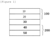
- FIG. 1 shows a laminated structure of a lithium secondary battery according to an exemplary embodiment of the present application.
- a negative electrode 100 for a lithium secondary battery including a negative electrode active material layer 20 on one surface of a negative electrode current collector layer 10 can be seen
- a positive electrode 200 for a lithium secondary battery including a positive electrode active material layer 40 on one surface of a positive electrode current collector layer 50 can be seen
- the negative electrode 100 for a lithium secondary battery and the positive electrode 200 for a lithium secondary battery are formed in a laminated structure with a separator 30 interposed therebetween.
- the silicon-based negative electrode includes a negative electrode current collector layer; and a negative electrode active material layer including a negative electrode active material layer composition provided on one surface or both surfaces of the negative electrode current collector layer, in which the negative electrode active material layer composition includes one or more selected from the group consisting of a silicon-based active material, a negative electrode conductive material, and a negative electrode binder.
- the silicon-based active material may particularly use pure silicon (Si) as the silicon-based active material.
- the capacity of the silicon-based active material is significantly higher than that of a graphite-based active material that is typically used, so that there have been more attempts to apply the same.
- the volume expansion rate of the silicon-based active material during charging/discharging is high, so that only a small amount thereof is mixed with a graphite-based active material for use.
- the active material included in the silicon-based negative electrode is very rough, as compared with a carbon-based negative electrode, the active material punctures the separator to come into contact with the positive electrode, thereby generating micro shorts.
- the lithium secondary battery of the present application even when the negative electrode having a very rough surface as described above is used, physical properties of the separator described later are adjusted to secure excellent capacity characteristics and energy density and to prevent micro shorts.
- An average particle diameter (D50) of the silicon-based active material of the present invention may be 5 um to 10 um, specifically 5.5 um to 8 ⁇ m, and more specifically 6 um to 7 um.
- D50 average particle diameter
- a specific surface area of the particles is within a suitable range, so that a viscosity of a negative electrode slurry is formed within an appropriate range. Accordingly, the particles constituting the negative electrode slurry are smoothly dispersed.
- the size of the silicon-based active material has a value equal to or greater than the lower limit value
- a contact area between the silicon particles and the conductive material is excellent due to the composite made of the conductive material and the negative electrode binder in the negative electrode slurry, so that a possibility of sustaining conductive network increases, thereby increasing the capacity retention rate.
- the average particle diameter satisfies the above range
- excessively large silicon particles are excluded, so that a surface of the negative electrode is formed smooth. Accordingly, a current density non-uniformity phenomenon during charging and discharging can be prevented.
- the silicon-based active material generally has a characteristic BET specific surface area.
- the BET specific surface area of the silicon-based active material is preferably 0.01 to 150.0 m 2 /g, more preferably 0.1 to 100.0 m 2 /g, particularly preferably 0.2 to 80.0 m 2 /g, and most preferably 0.2 to 18.0 m 2 /g.
- the BET specific surface area is measured in accordance with DIN 66131 (using nitrogen).
- the silicon-based active material may be present, for example, in a crystalline or amorphous form, and is preferably not porous.
- the silicon particles are preferably spherical or splinter-shaped particles.
- the silicon particles may also have a fiber structure or be present in the form of a silicon-containing film or coating.
- the silicon-based active material may be included in an amount of 60 parts by weight or more, on the basis of 100 parts by weight of the negative electrode active material layer composition.
- the silicon-based active material may be included in an amount of 60 parts by weight or more, preferably 65 parts by weight or more, and more preferably 70 parts by weight or more, and 95 parts by weight or less, preferably 90 parts by weight or less, and more preferably 80 parts by weight or less on the basis of 100 parts by weight of the negative electrode active material layer composition.
- the negative electrode active material layer composition according to the present application uses the specific conductive material and binder capable of controlling the volume expansion rate during charging and discharging even when the silicon-based active material having a significantly high capacity is used within the above range. Accordingly, even when the silicon-based active material is within the above range, the negative electrode active material layer composition does not degrade the performance of the negative electrode and has excellent output characteristics in charging and discharging.
- the silicon-based active material may have a non-spherical shape and its sphericity is, for example, 0.9 or less, for example, 0.7 to 0.9, for example 0.8 to 0.9, and for example 0.85 to 0.9.
- Equation A-1 the sphericity (circularity) is determined by Equation A-1, in which A is an area and P is a boundary line. 4 ⁇ A / P 2
- the negative electrode conductive material may include one or more selected from the group consisting of a particulate conductive material, a linear conductive material, and a planar conductive material.
- the particulate conductive material refers to a conductive material that may be used for improving conductivity of the negative electrode, has conductivity without causing a chemical change and has a spherical or point shape.
- the particulate conductive material may be at least one species selected from the group consisting of natural graphite, artificial graphite, carbon black, acetylene black, Ketjen black, channel black, furnace black, lamp black, thermal black, conductive fiber, fluorocarbon, aluminum powder, nickel powder, zinc oxide, potassium titanate, titanium oxide, and a polyphenylene derivative, and preferably may include carbon black in terms of high conductivity and excellent dispersibility.
- the particulate conductive material may have a BET specific surface area of 40 m 2 /g or greater and 70 m 2 /g or less, preferably 45 m 2 /g or greater and 65 m 2 /g or less, and more preferably 50 m 2 /g or greater and 60 m 2 /g or less.
- a functional group content (volatile matter) of the particulate conductive material may satisfy a range of 0.01% or more and 0.05% or less, preferably 0.01% or more and 0.04% or less, and more preferably 0.01% or more and 0.03% or less.
- the dispersibility of the particulate conductive material is improved, even when the content of the particulate conductive material is increased in the negative electrode slurry having the same solid content, the viscosity of the negative electrode slurry can be maintained at an appropriate level, so that processibility is stable and uniformity of the negative electrode to be formed can be improved.
- the particle diameter of the particulate conductive material may be 10 nm to 100 nm, preferably 20 nm to 90 nm, and more preferably 20 nm to 60 nm.
- the conductive material may include a planar conductive material.
- the planar conductive material can serve to improve conductivity by increasing surface contact between silicon particles in the negative electrode, and at the same time, to suppress the disconnection of the conductive path due to the volume expansion, and may be expressed as a plate-like conductive material or a bulk-type conductive material.
- the planar conductive material may include at least one selected from the group consisting of plate-like graphite, graphene, graphene oxide, and graphite flakes, and preferably may be plate-like graphite.
- the average particle diameter (D50) of the planar conductive material may be 2 um to 7 um, specifically 3 um to 6 ⁇ m, and more specifically 4 um to 5 um.
- D50 the average particle diameter of the planar conductive material
- the negative electrode composition in which the planar conductive material has D10 of 0.5 um or greater and 1.5 ⁇ m or less, D50 of 2.5 um or greater and 3.5 um or less and D90 of 7.0 um or greater and 15.0 ⁇ m or less.
- planar conductive material for the planar conductive material, a planar conductive material with a high specific surface area having a high BET specific surface area or a planar conductive material with a low specific surface area may be used.
- planar conductive material for the planar conductive material, a planar conductive material with a high specific surface area or a planar conductive material with a low specific surface area may be used without limitation.
- the planar conductive material according to the present application can be affected to some extent in the electrode performance by the dispersion effect, so that a planar conductive material with a low specific surface area that does not cause a problem in dispersion is used particularly preferably.
- the planar conductive material may have a BET specific surface area of 5 m 2 /g or greater.
- the planar conductive material may have a BET specific surface area of 5 m 2 /g or greater and 500m 2 / g or less, preferably 5 m 2 /g or greater and 300 m 2 /g or less, and more preferably 5 m 2 /g or greater and 250 m 2 /g or less.
- the planar conductive material is a planar conductive material with a high specific surface area, and the BET specific surface area may satisfy a range of 50 m 2 /g or greater and 500 m 2 /g or less, preferably 80 m 2 /g or greater and 300 m 2 /g or less, and more preferably 100 m 2 /g or greater and 300 m 2 /g or less.
- the planar conductive material is a planar conductive material with a low specific surface area
- the BET specific surface area may satisfy a range of 5 m 2 /g or greater and 40 m 2 /g or less, preferably 5 m 2 /g or greater and 30 m 2 /g or less, and more preferably 5 m 2 /g or greater and 25 m 2 /g or less.
- Other conductive materials may include linear conductive materials such as carbon nanotubes.
- the carbon nanotubes may be bundle-type carbon nanotubes.
- the bundle-type carbon nanotubes may include a plurality of carbon nanotube units.
- the term 'bundle type' herein refers to, unless otherwise specified, a bundle or rope-shaped secondary shape in which a plurality of carbon nanotube units are aligned side by side in such an orientation that longitudinal axes of the carbon nanotube units are substantially the same, or are entangled.
- the carbon nanotube unit has a graphite sheet having a cylindrical shape with a nano-sized diameter, and has an sp2 bonding structure.
- the characteristics of a conductor or a semiconductor may be exhibited depending on the rolled angle and structure of the graphite sheet.
- the bundle-type carbon nanotubes can be more uniformly dispersed during the manufacture of the negative electrode, and can form more smoothly a conductive network in the negative electrode to improve the conductivity of the negative electrode.
- the negative electrode conductive material may include a linear conductive material and the linear conductive material may be carbon nanotubes.
- the carbon nanotubes may be SWCNT or/and MWCNT.
- a length of the SWCNT may be 0.5 um to 100 ⁇ m, and preferably 1 um to 80 um.
- the negative electrode conductive material may be included in an amount of 10 parts by weight or more and 40 parts by weight or less, on the basis of 100 parts by weight of the negative electrode active material layer composition.
- the negative electrode conductive material may be included in an amount of 10 parts by weight or more and 40 parts by weight or less, preferably 10 parts by weight or more and 30 parts by weight or less, and more preferably 10 parts by weight or more and 20 parts by weight or less, on the basis of 100 parts by weight of the negative electrode active material layer composition.
- the negative electrode conductive material according to the present application has a completely different configuration from a conductive material that is applied to the positive electrode. That is, the negative electrode conductive material according to the present application serves to hold the contact between silicon-based active materials whose volume expansion of the electrode is very large due to charging and discharging, and the positive electrode conductive material serves to impart some conductivity while serving as a buffer at the time of rollpressing, and is completely different from the negative electrode conductive material of the present invention in terms of configuration and role.
- the negative electrode conductive material according to the present application is applied to a silicon-based active material, and has a completely different configuration from that of a conductive material that is applied to a graphite-based active material. That is, since a conductive material that is used for an electrode having a graphite-based active material simply has smaller particles than the active material, the conductive material has characteristics of improving output characteristics and imparting some conductivity, and are completely different from the negative electrode conductive material that is applied together with the silicon-based active material as in the present invention, in terms of configuration and role.
- the plate-like conductive material that is used as the negative electrode conductive material described above has a different structure and role from those of the carbon-based active material that is generally used as the negative electrode active material.
- the carbon-based active material that is used as the negative electrode active material may be artificial graphite or natural graphite, and refers to a material that is processed into a spherical or particulate shape and used so as to facilitate storage and release of lithium ions.
- the planar (plate-like) conductive material that is used as the negative electrode conductive material is a planar or plate-like material, and may be expressed as plate-like graphite. That is, the planar conductive material is a material that is included so as to maintain a conductive path in the negative electrode active material layer, and refers to a material for securing a conductive path in a planar shape inside the negative electrode active material layer, rather than playing a role in storing and releasing lithium.
- planar (plate-like) graphite as a conductive material means that graphite is processed into a planar or plate-like shape and used as a material for securing a conductive path rather than playing a role in storing or releasing lithium.
- the negative electrode active material included together has high capacity characteristics with respect to storing and releasing lithium, and serves to store and release all lithium ions transferred from the positive electrode.
- the use of a carbon-based active material as an active material means that the carbon-based active material is processed into a point or spherical shape and used as a material for storing or releasing lithium.
- artificial graphite or natural graphite which is a carbon-based active material, has a particulate shape, and a BET specific surface area thereof may satisfy a range of 0.1 m 2 /g or greater and 4.5 m 2 /g or less.
- plate-like graphite which is a planar conductive material, has a planar shape, and a BET specific surface area thereof may be 5 m 2 /g or greater.
- the negative electrode binder may include at least one selected from the group consisting of polyvinylidenefluoride-hexafluoropropylene copolymer (PVDF-co-HFP), polyvinylidenefluoride, polyacrylonitrile, polymethylmethacrylate, polyvinylalcohol, carboxymethylcellulose (CMC), starch, hydroxypropylcellulose, regenerated cellulose, polyvinylpyrrolidone, polytetrafluoroethylene, polyethylene, polypropylene, polyacrylic acid, ethylene-propylene-diene monomer (EPDM), sulfonated EPDM, styrene butadiene rubber (SBR), fluoro rubber, poly acrylic acid, and the above-mentioned materials in which a hydrogen is substituted with Li, Na, Ca, etc., and may also include various copolymers thereof.
- PVDF-co-HFP polyvinylidenefluoride-hexafluoropropylene copoly
- the negative electrode binder according to the exemplary embodiment of the present application serves to hold the active material and the conductive material in order to prevent distortion and structural deformation of the negative electrode structure in volume expansion and relaxation of the silicon-based active material.
- all of the general binders can be applied.
- a water-based binder may be used, and more specifically, a PAM-based binder may be used.
- the negative electrode binder may be included in an amount of 30 parts by weight or less, preferably 25 parts by weight or less, more preferably 20 parts by weight or less, and 5 parts by weight or more, preferably 10 parts by weight or more, on the basis of 100 parts by weight of the negative electrode active material layer composition.
- the negative electrode current collector layer generally has a thickness of 1 ⁇ m to 100 um.
- the negative electrode current collector layer is not particularly limited as long as it has high conductivity without causing a chemical change in the battery.
- copper, stainless steel, aluminum, nickel, titanium, fired carbon, copper or stainless steel each surface-treated with carbon, nickel, titanium, silver, or the like, an aluminum-cadmium alloy, or the like may be used.
- the negative electrode current collector layer may have microscopic irregularities formed on a surface to enhance a coupling force of the negative electrode active material, and may be used in various forms such as a film, a sheet, a foil, a net, a porous body, a foamed body, or a non-woven fabric body.
- the lithium secondary battery in which a thickness of the negative electrode current collector layer is 1 um or greater and 100 um or less and a thickness of the negative electrode active material layer is 10 um or greater and 100 ⁇ m or less.
- the lithium secondary battery in which the thickness of the negative electrode active material layer is 10 um or greater and 100 ⁇ m or less.
- the thicknesses may be variously modified depending on a type and use of the negative electrode used, and are not limited thereto.
- a porosity of the negative electrode active material layer may satisfy a range of 10% or greater and 60% or less.
- the porosity of the negative electrode active material layer may satisfy a range of 10% or greater and 60% or less, preferably 20% or greater and 50% or less, and more preferably 30% or greater and 45% or less.
- the porosity varies depending on compositions and contents of the silicon-based active material, conductive material and binder included in the negative electrode active material layer, and in particular, satisfies the range of the porosity described above when the silicon-based active material and the conductive material according to the present application are included in the specific compositions and contents, so that the electrode has appropriate ranges of electrical conductivity and resistance.
- the separator according to the present application satisfies all of the three conditions described above, and each condition will be described below.
- the separator according to an exemplary embodiment of the present specification satisfies a thickness of 1 um or greater and 15 ⁇ m or less.
- the separator according to another exemplary embodiment may satisfy a thickness of 1 um or greater and 15 um or less, preferably 3 um or greater and 15 um or less, more preferably 6 um or greater and 15 um or less, and 10 um or greater and 15 um or less.
- the thickness of the separator may refer to a thickness of one sheet when one sheet is used, and a total thickness range including thicknesses of two or more sheets when two or more sheets are used.
- the thickness of the separator When the thickness of the separator satisfies the above range, damage to the separator can be minimized even if contact occurs during expansion of a silicon-based negative electrode having a rough surface. If the thickness is below the range, the separator may be punctured due to expansion of the negative electrode even when the conditions of the compression resistance and the dielectric breakdown voltage described below are satisfied. If the thickness is above the range, lithium ion exchange between the positive electrode and the negative electrode may not be smoothly performed, resulting in defects in the lithium secondary battery.
- the compression resistance of the separator defined by Equation 1 below may satisfy a range of 1% or greater and 14.5% or less.
- the compression resistance defined by Equation 1 may satisfy a range of 1% or greater and 14.5% or less, 5% or greater and 14.5% or less, 10% or more and 14.5% or less, or 10.5% or greater and 14.5% or less.
- the compression resistance of Equation 1 may refer to a ratio of a thickness after a pressure is applied to the separator under a certain range of conditions and a thickness when no pressure is applied, and the low compression resistance may mean that the separator is less pressed.
- the compression resistance When the compression resistance satisfies the above range, the durability of the separator is increased. If the compression resistance is below the above range, the separator does not respond flexibly to the negative electrode having a rough surface, resulting in breakage or puncture of the separator. If the compression resistance exceeds the above range, the separator is too robust, making it difficult for lithium ions to pass therethrough, which may cause an increase in diffusion resistance.
- a separator composed of only an inorganic material layer without polymers, such as PE or PP, is evaluated very low for the compression resistance.
- the separator becomes in a state of being little compressed, so that the pores of the separator remain at an initial state, as they are.
- the passing of lithium ions becomes smooth during charging and discharging and the diffusion resistance does not increase any more.
- the dielectric breakdown voltage of the separator may be 400 V or higher.
- the dielectric breakdown voltage of the separator may satisfy a range of 400 V or higher, and preferably 450 V or higher, and may satisfy a range of 6000 V or lower, and preferably 5000 V or lower, or a range of 2000 V or lower.
- the dielectric breakdown voltage refers to a voltage at a time of dielectric breakdown when stepping up a monocell including the separator from 0 V to 6000 V at a rate of 100 V/s with Hipot tester (AC/DC/IR Tester) available from Chroma, and may mean that the higher the measured voltage is, the separator can withstand a higher voltage.
- the dielectric breakdown voltage When the dielectric breakdown voltage satisfies the above range, the durability of the separator is increased. If the dielectric breakdown voltage is below the above range, the separator may be broken or punctured by the negative electrode having a rough surface. The fact that the dielectric breakdown voltage is measured means that electric charges flow, and if the dielectric breakdown voltage is below the lower limit of the range as described above, it may be determined that a short has occurred.
- the separator according to the present application is characterized in that only when all of the three conditions described above are satisfied, the lithium secondary battery can be driven without damage to the separator despite the volume expansion of the silicon-based negative electrode having a rough surface.
- the compression resistance and the dielectric breakdown voltage may be made to satisfy the above ranges by adjusting a molecular weight and an internal pore distribution of the separator.
- the separator according to the present application satisfies the ranges of the compression resistance and dielectric breakdown voltage by adjusting the molecular weight and, at the same time, the thickness in order to satisfy the above ranges.
- the pore distribution is adjusted together in order to satisfy the ranges of the compression resistance and dielectric breakdown voltage.
- the ranges of the compression resistance and dielectric breakdown voltage can be adjusted to the above ranges.
- the separator according to the present application is characterized in that the compression resistance and the dielectric breakdown voltage are satisfied by adjusting the molecular weight range, the internal pore distribution, and the thickness range to suitable ranges.
- a weight average molecular weight of the separator may include a range of 1,000,000 g/mol or more and 10,000,000 g/mol or less.
- the weight average molecular weight of the separator may satisfy a range of 1,000,000 g/mol or more and 10,000,000 g/mol or less, preferably 1,000,000 g/mol or more and 9,000,000 g/mol or less, and more preferably 1,000,000 g/mol or more and 8,000,000 g/mol or less.
- a pore size of the separator may satisfy a range of 10 nm or greater and 100 nm or smaller, and specifically, 20 nm or greater and 60 nm or smaller, and the distribution may be appropriately adjusted according to the size of the pores, thereby adjusting the compression resistance and the dielectric breakdown voltage.
- the compression resistance and dielectric breakdown voltage can be increased.
- the separator for a lithium secondary battery in which the separator is a wet separator, or a dry separator.
- the wet separator and the dry separator may be classified according to differences in the process itself.
- the wet separator may be obtained by extruding a mixture of polyethylene and paraffin, and passing the mixed film through methylene chloride (MC) to melt the paraffin.
- MC methylene chloride
- polyethylene is not dissolved in methylene chloride (MC), and pores are created at sites where the paraffin is melted, resulting in the wet separator.
- the dry separator may be manufactured in a manner of extruding a polypropylene polymer into a film and then stretching the film to create gaps between polymer chains.
- the separator for a lithium secondary battery in which the separator includes one or more selected from the group consisting of a porous polymer film, a porous non-woven fabric, and a ceramic component.
- the separator serves to separate the negative electrode and the positive electrode and to provide a movement path of lithium ions
- any separator may be used as the separator without particular limitation as long as it is typically used in a secondary battery, and particularly, a separator having high moisture-retention ability for an electrolyte solution as well as a low resistance to the movement of electrolyte solution ions may be preferably used.
- a porous polymer film for example, a porous polymer film manufactured from a polyolefin-based polymer, such as an ethylene homopolymer, a propylene homopolymer, an ethylene/butene copolymer, an ethylene/hexene copolymer, and an ethylene/methacrylate copolymer, or a laminated structure having two or more layers thereof may be used.
- a typical porous non-woven fabric for example, a non-woven fabric formed of high melting point glass fibers, polyethylene terephthalate fibers, or the like may be used.
- a coated separator including a ceramic component or a polymer material may be used to secure heat resistance or mechanical strength, and the separator having a single layer or multilayer structure may be selectively used.
- the separator of the present application falls within the ranges that satisfy the three parameters described above, the separator may be used without limitation in terms of types.
- the separator may include a single layer or two or more layers.
- the positive electrode may include a positive electrode current collector layer and a positive electrode active material layer formed on the positive electrode current collector layer and including the positive electrode active material.
- the positive electrode current collector layer is not particularly limited as long as it has conductivity without causing a chemical change in the battery.
- stainless steel, aluminum, nickel, titanium, fired carbon, aluminum or stainless steel each surface-treated with carbon, nickel, titanium, silver, or the like, or the like may be used.
- the positive electrode current collector layer may typically have a thickness of 3 to 500 um, and a surface of the current collector may be formed with microscopic irregularities to enhance adhesive force of the positive electrode active material.
- the positive electrode current collector layer may be used in various forms such as a film, a sheet, a foil, a net, a porous body, a foamed body, and a non-woven fabric body.
- the positive electrode active material may be a positive electrode active material that is typically used.
- the positive electrode active material may be a layered compound such as a lithium cobalt oxide (LiCoO 2 ) and a lithium nickel oxide (LiNiO 2 ), or a compound substituted with one or more transition metals; a lithium iron oxide such as LiFe 3 O 4 ; a lithium manganese oxide such as chemical formula Li 1+c1 Mn 2-c1 O 4 (0 ⁇ c1 ⁇ 0.33), LiMnO 3 , LiMn 2 O 3 and LiMnO 2 ; a lithium copper oxide (Li 2 CuO 2 ); a vanadium oxide such as LiV 3 O 8 , V 2 O 5 and Cu 2 V 2 O 7 ; a Ni-site type lithium nickel oxide represented by chemical formula LiNi 1-c2 M c2 O 2 (where M is at least one selected from the group consisting of Co, Mn, Al, Cu, Fe, Mg, B, and Ga, and satisfies 0.01 ⁇
- the positive electrode active material layer may include a positive electrode conductive material and a positive electrode binder together with the positive electrode active material described above.
- the positive electrode conductive material is used to impart conductivity to the electrode, and can be used without particular limitation as long as the positive electrode conductive material has electronic conductivity without causing a chemical change in a battery.
- Specific examples may include graphite such as natural graphite and artificial graphite; a carbon-based material such as carbon black, acetylene black, Ketjen black, channel black, furnace black, lamp black, thermal black and carbon fiber; metal powders or metal fibers such as copper, nickel, aluminum and silver; a conductive whisker such as zinc oxide and potassium titanate; a conductive metal oxide such as titanium oxide; or a conductive polymer such as polyphenylene derivative, or the like, and any one thereof or a mixture of two or more thereof may be used.
- the positive electrode binder serves to improve adhesion between particles of the positive electrode active material and adhesive force between the positive electrode active material and the positive electrode current collector layer.
- Specific examples may include polyvinylidene fluoride (PVDF), vinylidene fluoride-hexafluoropropylene copolymer (PVDF-co-HFP), polyvinyl alcohol, polyacrylonitrile, carboxymethylcellulose (CMC), starch, hydroxypropylcellulose, regenerated cellulose, polyvinylpyrrolidone, polytetrafluoroethylene, polyethylene, polypropylene, ethylene-propylene-diene polymer (EPDM), sulfonated-EPDM, styrene butadiene rubber (SBR), fluoro rubber, or various copolymers thereof, and the like, and any one thereof or a mixture of two or more thereof may be used.
- PVDF polyvinylidene fluoride
- PVDF-co-HFP vinylidene fluoride-
- the electrolyte solution may include an organic liquid electrolyte solution, an inorganic liquid electrolyte solution, a solid polymer electrolyte solution, a gel-type polymer electrolyte solution, a solid inorganic electrolyte solution, a molten-type inorganic electrolyte solution and the like that may be used in the manufacturing of the lithium secondary battery, but are not limited thereto.
- the electrolyte solution may include a non-aqueous organic solvent and a metal salt.
- an aprotic organic solvent such as N-methyl-2-pyrrolidinone, propylene carbonate, ethylene carbonate, butylene carbonate, dimethyl carbonate, diethyl carbonate, gamma-butyrolactone, 1,2-dimetoxy ethane, tetrahydrofuran, 2-methyltetrahydrofuran, dimethylsulfoxide, 1,3-dioxolane, formamide, dimethylformamide, dioxolane, acetonitrile, nitromethane, methyl formate, methyl acetate, phosphoric acid triester, trimethoxy methane, dioxolane derivative, sulfolane, methyl sulfolane, 1,3-dimethyl-2-imidazolidinone, propylene carbonate derivative, tetrahydrofuran derivative, ether, methyl propionate, or ethyl propionate may be used.
- an aprotic organic solvent such as N-methyl-2-
- ethylene carbonate and propylene carbonate which are cyclic carbonates
- a linear carbonate with low viscosity and low permittivity such as dimethyl carbonate or diethyl carbonate
- an electrolyte solution and having high electric conductivity may be prepared, and therefore, may be more preferably used.
- a lithium salt may be used as the metal salt, and the lithium salt is a material that is readily soluble in the non-aqueous electrolyte solution, in which, for example, one or more species selected from the group consisting of F - , Cl - , I - , NO 3 - , N(CN) 2- , BF 4 - , ClO 4 - , PF 6 - , (CF 3 ) 2 PF 4 - , (CF 3 ) 3 PF 3 - , (CF 3 ) 4 PF 2 - , (CF 3 ) 5 PF - , (CF 3 ) 6 P - , CF 3 SO 3 - , CF 3 CF 2 SO 3 - , (CF 3 SO 2 ) 2 N - , (FSO 2 ) 2 N - , CF 3 CF 2 (CF 3 ) 2 CO - , (CF 3 SO 2 ) 2 CH - , (SF 5 ) 3 C - , (CF
- One or more additives for example, a haloalkylene carbonate-based compound such as difluoroethylene carbonate, pyridine, triethylphosphite, triethanolamine, cyclic ether, ethylenediamine, n-glyme, hexaphosphoric triamide, a nitrobenzene derivative, sulfur, a quinone imine dye, N-substituted oxazolidinone, N,N-substituted imidazolidine, ethylene glycol dialkyl ether, an ammonium salt, pyrrole, 2-methoxy ethanol, or aluminum trichloride, may be further included in the electrolyte solution for the purpose of improving lifetime characteristics of the battery, suppressing a decrease in battery capacity, improving discharge capacity of the battery, and the like, in addition to the above-described electrolyte solution components.
- a haloalkylene carbonate-based compound such as difluoroethylene carbonate, pyridine, triethy
- An exemplary embodiment of the present invention provides a battery module including the secondary battery as a unit cell, and a battery pack including the same. Since the battery module and the battery pack include the secondary battery having high capacity, high rate capability, and high cycle characteristics, the battery module and the battery pack may be used as a power source of a medium to large sized device selected from the group consisting of an electric vehicle, a hybrid electric vehicle, a plug-in hybrid electric vehicle, and a power storage system.
- Si slurry was manufactured by mixing inorganic Si (Wacker), polyacrylamide (Aldrich), and conductive material (Super-C, Immerys) in a ratio of 7:2:1 to a concentration of 34 wt.% in DI water.
- the slurry was applied to both surfaces of an 8 ⁇ mthick Cu foil (SK Nexilis), which was then press-rolled to manufacture a negative electrode having a total negative electrode thickness of 53 ⁇ m.
- a positive electrode slurry having a solid substance concentration of 75.5% was manufactured by mixing an NCMA positive electrode material (HN803 Grade available from LG Chem) and a PVdF binder (KF9709 available from Arkema) in a ratio of 97.74:2.26 in an NMP solvent.
- NCMA positive electrode material HN803 Grade available from LG Chem
- PVdF binder KF9709 available from Arkema
- the positive electrode slurry was applied to both surfaces of a 12 ⁇ m-thick Al foil (A1100 grade available from Sama Aluminum), which was then press-rolled to manufacture a positive electrode having a final positive electrode thickness of 142 um.
- Example 1 Example 2
- Example 3 Example 4 Comparative Example 1 Comparati ve Example 2 Web thickness ( ⁇ m) 14.6 12.1 11.2 11.9 11.5 9.2 Compression resistance (%) 14.5 12.4 10.5 11.0 14.8 15.0 Dielectric breakdown voltage (V) 1526 484 495 452 325 198
- the thickness (T1) after stacking the three separators in Table 1 was measured, the thickness (T2) after pressing the separators at 2000 kgf and 70°C for 10 seconds with a hot press (QM-940A Grade available from Q-MESYS) was measured, and the calculation was performed according to Equation 1 above.
- V Dielectric breakdown voltage
- Example 1 Example 2
- Example 3 Example 4 Comparative Example 1 Comparative Example 2
- Short evaluation (Fail/Test) 0/ 20 0/ 20 1/ 20 2/ 20 8/ 20 18/ 20
- the separators for a lithium secondary battery according to Examples 1 to 4 satisfied all of the three parameters, i.e., the thickness of 1 um or greater and 15 ⁇ m or less, the compression resistance of 1% or greater and 14.5% or less defined by Equation 1 and the dielectric breakdown voltage of 400V or higher, and therefore, could maintain a robust shape even when the rough negative electrode surface came into contact with the separators due to volume expansion of the silicon-based negative electrode during charging and discharging, which could be confirmed through the test in Table 2.
Landscapes
- Chemical & Material Sciences (AREA)
- Chemical Kinetics & Catalysis (AREA)
- Electrochemistry (AREA)
- General Chemical & Material Sciences (AREA)
- Engineering & Computer Science (AREA)
- Manufacturing & Machinery (AREA)
- Materials Engineering (AREA)
- Inorganic Chemistry (AREA)
- Battery Electrode And Active Subsutance (AREA)
- Secondary Cells (AREA)
- Cell Separators (AREA)
Abstract
Description
- This application claims priority to and the benefit of
Korean Patent Application No. 10-2022-0012968 filed in the Korean Intellectual Property Office on January 28, 2022 - The present application relates to a lithium secondary battery including a separator.
- Due to the rapid increase in the use of fossil fuels, the demand for the use of alternative energy or clean energy is increasing, and as part thereof, the fields that are being studied most actively are the fields of power generation and power storage using an electrochemical reaction.
- At present, a secondary battery is a representative example of an electrochemical device that utilizes such electrochemical energy, and the range of use thereof tends to be gradually expanding.
- Along with the technology development and the increase in demand for mobile devices, the demand for secondary batteries as an energy source is sharply increasing. Among such secondary batteries, lithium secondary batteries having high energy density and voltage, long cycle life, and low self-discharging rate have been commercialized and widely used. In addition, research is being actively conducted on a method for manufacturing a high-density electrode having a higher energy density per unit volume as an electrode for such a high-capacity lithium secondary battery.
- In general, a secondary battery includes a positive electrode, a negative electrode, an electrolyte, and a separator. The negative electrode includes a negative electrode active material for intercalating and deintercalating lithium ions to and from the positive electrode, and silicon-based particles having a high discharge capacity may be used as the negative electrode active material.
- In particular, according to the demand for high density energy batteries in recent years, research is being actively conducted on a method for increasing a capacity by using together a silicon-based compound such as Si/C and SiOx having a
capacity 10 times or higher than that of a graphite-based material, as a negative electrode active material. However, as compared to graphite that is typically used, a silicon-based compound that is a high capacity material has a large capacity but undergoes rapid volume expansion during charging, thereby disconnecting a conductive path to degrade battery characteristics. - In addition, the silicon-based negative electrode undergoes a carbonization process, and in this case, 50% or more of the negative electrode binder included in the silicon-based negative electrode is lost, resulting in a very rough surface. That is, in the process of carbonizing the silicon-based negative electrode, a surface of the silicon-based negative electrode becomes very rough, and as a result, the negative electrode punctures the separator to come into contact with the positive electrode, thereby generating micro shorts.
- Therefore, in order to address the problem occurring when using a silicon-based compound as a negative electrode active material, a method of adding a coating layer on a surface of the separator, a method of changing a material of the separator, etc. are being studied as solutions, but a suitable solution is not currently available.
- Therefore, there is a need for research on a separator capable of withstanding the pressure and roughness when the separator is compressed due to expansion of the silicon-based negative electrode having a rough surface during charging and discharging.
-
Japanese Patent Laid-open Application Publication No. 2009-080971 - As a result of research on a separator capable of withstanding the pressure and roughness when the separator is compressed due to the expansion of the silicon-based negative electrode having a rough surface during charging and discharging, it has been found by the research that the above problems can be solved when adjusting physical properties of the separator itself, and accordingly, the present application relates to a lithium secondary battery including a separator satisfying specific conditions.
- An exemplary embodiment of the present specification provides a lithium secondary battery including: a silicon-based negative electrode; a positive electrode; a separator positioned between the negative electrode and the positive electrode; and an electrolyte, in which the silicon-based negative electrode includes a negative electrode current collector layer, and a negative electrode active material layer including a negative electrode active material layer composition provided on one surface or both surfaces of the negative electrode current collector layer, in which the negative electrode active material layer composition includes one or more selected from the group consisting of a silicon-based active material, a negative electrode conductive material, and a negative electrode binder, in which the silicon-based active material includes one or more selected from the group consisting of SiOx (x=0) and SiOx (0<x<2), and includes the SiOx (x=0) in an amount of 70 parts by weight or more on the basis of 100 parts by weight of the silicon-based active material, and in which the separator satisfies a thickness of 1 um or greater and 15 µm or less, and has a compression resistance of 1% or greater and 14.5% or less defined by Equation 1 below, and a dielectric breakdown voltage of 400V or higher.

- T1 refers to an initial thickness in a state in which the separator is stacked in three sheets,
- T2 refers to a thickness after stacking the separator in three sheets and pressing them at 2000 kgf and 70°C for 10 seconds with a hot press (QM-940A Grade available from Q-mesys), and
- the dielectric breakdown voltage refers to a voltage at a time of dielectric breakdown while stepping up a monocell including the separator from 0V to 6000V at a rate of 100V/s with Hipot tester (AC/DC/IR Tester) available from Chroma.
- According to the lithium secondary battery of the exemplary embodiment of the present invention, the silicon-based negative electrode is used and the separator satisfies all of the three parameters, i.e., the thickness of 1 um to 15 um, the compression resistance of 1% or greater and 14.5% or less defined by Equation 1 and the dielectric breakdown voltage of 400V or higher so that the separator can maintain a robust shape even when the rough negative electrode surface comes into contact with the separator due to volume expansion of the silicon-based negative electrode during charging and discharging.
- That is, for the lithium secondary battery of the present application, the three parameters defined by the thickness range, the dielectric breakdown voltage, and the compression resistance of the separator are set to the appropriate ranges, resulting in addressing the existing problems occurring in lithium secondary batteries using silicon-based negative electrodes.
-
FIG. 1 shows a laminated structure of a lithium secondary battery according to an exemplary embodiment of the present application. -
- 10: negative electrode current collector layer
- 20: negative electrode active material layer
- 30: separator
- 40: positive electrode active material layer
- 50: positive electrode current collector layer
- 100: negative electrode for lithium secondary battery
- 200: positive electrode for lithium secondary Battery
- Before describing the present invention, some terms are first defined.
- When one part "includes", "comprises" or "has" one constituent element in the present specification, unless otherwise specifically described, this does not mean that another constituent element is excluded, but means that another constituent element may be further included.
- In the present specification, 'p to q' means a range of 'p or more and q or less'.
- In this specification, the "specific surface area" is measured by the BET method, and specifically, is calculated from a nitrogen gas adsorption amount under liquid nitrogen temperature (77K) by using BELSORP-mini II of BEL Japan. That is, in the present application, the BET specific surface area may refer to the specific surface area measured by the above measurement method.
- In the present specification, "Dn" refers to a particle size distribution, and refers to a particle diameter at the n% point in the cumulative distribution of the number of particles according to the particle diameter. That is, D50 is a particle diameter (center particle diameter, average particle diameter) at the 50% point in the cumulative distribution of the number of particles according to the particle diameter, D90 is a particle diameter at the 90% point in the cumulative distribution of the number of particles according to the particle diameter, and D10 is a particle diameter at the 10% point in the cumulative distribution of the number of particles according to the particle diameter. Meanwhile, the particle size distribution may be measured using a laser diffraction method. Specifically, powders to be measured are dispersed in a dispersion medium, which is then introduced into a commercially available laser diffraction particle size measurement apparatus (for example, Microtrac S3500) in which a difference in diffraction patterns according to the particle size is measured, when a laser beam passes through particles, and then a particle size distribution is calculated.
- In the present specification, the description "a polymer includes a certain monomer as a monomer unit" means that the monomer participates in a polymerization reaction and is included as a repeating unit in the polymer. In the present specification, when a polymer includes a monomer, this is interpreted as the same as that the polymer includes a monomer as a monomer unit.
- In the present specification, it is understood that the term 'polymer' is used in a broad sense including a copolymer unless otherwise specified as 'a homopolymer'.
- In the present specification, a weight-average molecular weight (Mw) and a number-average molecular weight (Mn) are polystyrene converted molecular weights measured by gel permeation chromatography (GPC) while employing, as a standard material, a monodispersed polystyrene polymer (standard sample) having various degrees of polymerization commercially available for measuring a molecular weight. In the present specification, a molecular weight refers to a weight-average molecular weight unless particularly described otherwise.
- Hereinafter, exemplary embodiments of the present invention will be described in detail with reference to the drawings so that one skilled in the art can readily implement the present invention. However, the present invention may be embodied in various different forms, and is not limited to the following descriptions.
- An exemplary embodiment of the present specification provides a lithium secondary battery including: a silicon-based negative electrode; a positive electrode; a separator positioned between the negative electrode and the positive electrode; and an electrolyte, in which the silicon-based negative electrode includes a negative electrode current collector layer, and a negative electrode active material layer including a negative electrode active material layer composition provided on one surface or both surfaces of the negative electrode current collector layer, in which the negative electrode active material layer composition includes one or more selected from the group consisting of a silicon-based active material, a negative electrode conductive material, and a negative electrode binder, in which the silicon-based active material includes one or more selected from the group consisting of SiOx (x=0) and SiOx (0<x<2), and includes the SiOx (x=0) in an amount of 70 parts by weight or more on the basis of 100 parts by weight of the silicon-based active material, and in which the separator satisfies a thickness of 1 um or greater and 15 µm or less, and has a compression resistance of 1% or greater and 14.5% or less defined by Equation 1 below, and a dielectric breakdown voltage of 400V or higher.

- T1 refers to an initial thickness in a state in which the separator is stacked in three sheets,
- T2 refers to a thickness after stacking the separator in three sheets and pressing them at 2000 kgf and 70°C for 10 seconds with a hot press (QM-940A Grade available from Q-mesys), and
- the dielectric breakdown voltage refers to a voltage at a time of dielectric breakdown while stepping up a monocell including the separator from 0V to 6000V at a rate of 100V/s with Hipot tester (AC/DC/IR Tester) available from Chroma.
- The separator according to an exemplary embodiment of the present invention satisfies all of the three parameters, i.e., the thickness of 1 um or greater and 15 µm or less, the compression resistance of 1% or greater and 14.5% or less defined by Equation 1 and the dielectric breakdown voltage of 400V or higher, so that the separator can maintain a robust shape even when the rough negative electrode surface comes into contact with the separator due to volume expansion of the silicon-based negative electrode during charging and discharging.
-
FIG. 1 shows a laminated structure of a lithium secondary battery according to an exemplary embodiment of the present application. Specifically, anegative electrode 100 for a lithium secondary battery including a negative electrodeactive material layer 20 on one surface of a negative electrodecurrent collector layer 10 can be seen, apositive electrode 200 for a lithium secondary battery including a positive electrodeactive material layer 40 on one surface of a positive electrodecurrent collector layer 50 can be seen, and thenegative electrode 100 for a lithium secondary battery and thepositive electrode 200 for a lithium secondary battery are formed in a laminated structure with aseparator 30 interposed therebetween. - Hereinafter, the silicon-based negative electrode, which is one of the features of the present invention, will be described.
- In an exemplary embodiment of the present application, the silicon-based negative electrode includes a negative electrode current collector layer; and a negative electrode active material layer including a negative electrode active material layer composition provided on one surface or both surfaces of the negative electrode current collector layer, in which the negative electrode active material layer composition includes one or more selected from the group consisting of a silicon-based active material, a negative electrode conductive material, and a negative electrode binder.
- In an exemplary embodiment of the present application, there is provided the lithium secondary battery in which the silicon-based active material includes one or more selected from the group consisting of SiOx (x=0) and SiOx (0<x<2), and includes the SiOx (x=0) in an amount of 70 parts by weight or more on the basis of 100 parts by weight of the silicon-based active material.
- In another exemplary embodiment, on the basis of 100 parts by weight of the silicon-based active material, SiOx (x = 0) may be included in an amount of 70 parts by weight or more, preferably 80 parts by weight or more, and more preferably 90 parts by weight or more, and 100 parts by weight or less, preferably 99 parts by weight or less, and more preferably 95 parts by weight or less.
- In an exemplary embodiment of the present application, the silicon-based active material may particularly use pure silicon (Si) as the silicon-based active material. The use of pure silicon (Si) as the silicon-based active material may mean that, on the basis of 100 parts by weight of the total silicon-based active material as described above, pure Si particles (SiOx (x=0)) not bonded to other particles or elements are included within the above range.
- The capacity of the silicon-based active material is significantly higher than that of a graphite-based active material that is typically used, so that there have been more attempts to apply the same. However, the volume expansion rate of the silicon-based active material during charging/discharging is high, so that only a small amount thereof is mixed with a graphite-based active material for use.
- In addition, since a surface of the active material included in the silicon-based negative electrode is very rough, as compared with a carbon-based negative electrode, the active material punctures the separator to come into contact with the positive electrode, thereby generating micro shorts. However, according to the lithium secondary battery of the present application, even when the negative electrode having a very rough surface as described above is used, physical properties of the separator described later are adjusted to secure excellent capacity characteristics and energy density and to prevent micro shorts.
- An average particle diameter (D50) of the silicon-based active material of the present invention may be 5 um to 10 um, specifically 5.5 um to 8 µm, and more specifically 6 um to 7 um. When the average particle diameter is within the above range, a specific surface area of the particles is within a suitable range, so that a viscosity of a negative electrode slurry is formed within an appropriate range. Accordingly, the particles constituting the negative electrode slurry are smoothly dispersed. In addition, when the size of the silicon-based active material has a value equal to or greater than the lower limit value, a contact area between the silicon particles and the conductive material is excellent due to the composite made of the conductive material and the negative electrode binder in the negative electrode slurry, so that a possibility of sustaining conductive network increases, thereby increasing the capacity retention rate. In the meantime, when the average particle diameter satisfies the above range, excessively large silicon particles are excluded, so that a surface of the negative electrode is formed smooth. Accordingly, a current density non-uniformity phenomenon during charging and discharging can be prevented.
- In an exemplary embodiment of the present application, the silicon-based active material generally has a characteristic BET specific surface area. The BET specific surface area of the silicon-based active material is preferably 0.01 to 150.0 m2/g, more preferably 0.1 to 100.0 m2/g, particularly preferably 0.2 to 80.0 m2/g, and most preferably 0.2 to 18.0 m2/g. The BET specific surface area is measured in accordance with DIN 66131 (using nitrogen).
- In an exemplary embodiment of the present application, the silicon-based active material may be present, for example, in a crystalline or amorphous form, and is preferably not porous. The silicon particles are preferably spherical or splinter-shaped particles. Alternatively, but less preferably, the silicon particles may also have a fiber structure or be present in the form of a silicon-containing film or coating.
- In an exemplary embodiment of the present application, the silicon-based active material may be included in an amount of 60 parts by weight or more, on the basis of 100 parts by weight of the negative electrode active material layer composition.
- In another exemplary embodiment the silicon-based active material may be included in an amount of 60 parts by weight or more, preferably 65 parts by weight or more, and more preferably 70 parts by weight or more, and 95 parts by weight or less, preferably 90 parts by weight or less, and more preferably 80 parts by weight or less on the basis of 100 parts by weight of the negative electrode active material layer composition.
- The negative electrode active material layer composition according to the present application uses the specific conductive material and binder capable of controlling the volume expansion rate during charging and discharging even when the silicon-based active material having a significantly high capacity is used within the above range. Accordingly, even when the silicon-based active material is within the above range, the negative electrode active material layer composition does not degrade the performance of the negative electrode and has excellent output characteristics in charging and discharging.
- In an exemplary embodiment of the present application, the silicon-based active material may have a non-spherical shape and its sphericity is, for example, 0.9 or less, for example, 0.7 to 0.9, for example 0.8 to 0.9, and for example 0.85 to 0.9.
- In the present application, the sphericity (circularity) is determined by Equation A-1, in which A is an area and P is a boundary line.

- In the related art, it is general to use only graphite-based compounds as the negative electrode active material. However, in recent years, as the demand for high-capacity batteries is increasing, attempts to mix and use silicon-based compounds are increasing in order to increase capacity. However, the silicon-based compounds have limitations in that the volume rapidly expands during the charging/discharging, resulting in damage to the conductive path formed in the negative electrode active material layer to degrade the performance of the battery.
- Accordingly, in an exemplary embodiment of the present application, the negative electrode conductive material may include one or more selected from the group consisting of a particulate conductive material, a linear conductive material, and a planar conductive material.
- In an exemplary embodiment of the present application, the particulate conductive material refers to a conductive material that may be used for improving conductivity of the negative electrode, has conductivity without causing a chemical change and has a spherical or point shape. Specifically, the particulate conductive material may be at least one species selected from the group consisting of natural graphite, artificial graphite, carbon black, acetylene black, Ketjen black, channel black, furnace black, lamp black, thermal black, conductive fiber, fluorocarbon, aluminum powder, nickel powder, zinc oxide, potassium titanate, titanium oxide, and a polyphenylene derivative, and preferably may include carbon black in terms of high conductivity and excellent dispersibility.
- In an exemplary embodiment of the present application, the particulate conductive material may have a BET specific surface area of 40 m2/g or greater and 70 m2/g or less, preferably 45 m2/g or greater and 65 m2/g or less, and more preferably 50 m2/g or greater and 60 m2/g or less.
- In an exemplary embodiment of the present application, a functional group content (volatile matter) of the particulate conductive material may satisfy a range of 0.01% or more and 0.05% or less, preferably 0.01% or more and 0.04% or less, and more preferably 0.01% or more and 0.03% or less.
- Specifically, as the dispersibility of the particulate conductive material is improved, even when the content of the particulate conductive material is increased in the negative electrode slurry having the same solid content, the viscosity of the negative electrode slurry can be maintained at an appropriate level, so that processibility is stable and uniformity of the negative electrode to be formed can be improved.
- In an exemplary embodiment of the present application, the particle diameter of the particulate conductive material may be 10 nm to 100 nm, preferably 20 nm to 90 nm, and more preferably 20 nm to 60 nm.
- In an exemplary embodiment of the present application, the conductive material may include a planar conductive material.
- The planar conductive material can serve to improve conductivity by increasing surface contact between silicon particles in the negative electrode, and at the same time, to suppress the disconnection of the conductive path due to the volume expansion, and may be expressed as a plate-like conductive material or a bulk-type conductive material.
- In an exemplary embodiment of the present application, the planar conductive material may include at least one selected from the group consisting of plate-like graphite, graphene, graphene oxide, and graphite flakes, and preferably may be plate-like graphite.
- In an exemplary embodiment of the present application, the average particle diameter (D50) of the planar conductive material may be 2 um to 7 um, specifically 3 um to 6 µm, and more specifically 4 um to 5 um. When the above range is satisfied, the sufficient particle size results in easy dispersion without causing an excessive increase in viscosity of the negative electrode slurry. Therefore, the dispersion effect is excellent when dispersing using the same equipment and time.
- In an exemplary embodiment of the present application, there is provided the negative electrode composition in which the planar conductive material has D10 of 0.5 um or greater and 1.5 µm or less, D50 of 2.5 um or greater and 3.5 um or less and D90 of 7.0 um or greater and 15.0 µm or less.
- In an exemplary embodiment of the present application, for the planar conductive material, a planar conductive material with a high specific surface area having a high BET specific surface area or a planar conductive material with a low specific surface area may be used.
- In an exemplary embodiment of the present application, for the planar conductive material, a planar conductive material with a high specific surface area or a planar conductive material with a low specific surface area may be used without limitation. However, in particular, the planar conductive material according to the present application can be affected to some extent in the electrode performance by the dispersion effect, so that a planar conductive material with a low specific surface area that does not cause a problem in dispersion is used particularly preferably.
- In an exemplary embodiment of the present application, the planar conductive material may have a BET specific surface area of 5 m2/g or greater.
- In another exemplary embodiment, the planar conductive material may have a BET specific surface area of 5 m2/g or greater and 500m2/ g or less, preferably 5 m2/g or greater and 300 m2/g or less, and more preferably 5 m2/g or greater and 250 m2/g or less.
- In another exemplary embodiment, the planar conductive material is a planar conductive material with a high specific surface area, and the BET specific surface area may satisfy a range of 50 m2/g or greater and 500 m2/g or less, preferably 80 m2/g or greater and 300 m2/g or less, and more preferably 100 m2/g or greater and 300 m2/g or less.
- In another exemplary embodiment, the planar conductive material is a planar conductive material with a low specific surface area, and the BET specific surface area may satisfy a range of 5 m2/g or greater and 40 m2/g or less, preferably 5 m2/g or greater and 30 m2/g or less, and more preferably 5 m2/g or greater and 25 m2/g or less.
- Other conductive materials may include linear conductive materials such as carbon nanotubes. The carbon nanotubes may be bundle-type carbon nanotubes. The bundle-type carbon nanotubes may include a plurality of carbon nanotube units. Specifically, the term 'bundle type' herein refers to, unless otherwise specified, a bundle or rope-shaped secondary shape in which a plurality of carbon nanotube units are aligned side by side in such an orientation that longitudinal axes of the carbon nanotube units are substantially the same, or are entangled. The carbon nanotube unit has a graphite sheet having a cylindrical shape with a nano-sized diameter, and has an sp2 bonding structure. In this case, the characteristics of a conductor or a semiconductor may be exhibited depending on the rolled angle and structure of the graphite sheet. As compared with entangled-type carbon nanotubes, the bundle-type carbon nanotubes can be more uniformly dispersed during the manufacture of the negative electrode, and can form more smoothly a conductive network in the negative electrode to improve the conductivity of the negative electrode.
- In an exemplary embodiment of the present application, the negative electrode conductive material may include a linear conductive material and the linear conductive material may be carbon nanotubes.
- In an exemplary embodiment of the present application, the carbon nanotubes may be SWCNT or/and MWCNT. When the linear conductive material is SWCNT, a length of the SWCNT may be 0.5 um to 100 µm, and preferably 1 um to 80 um.
- In an exemplary embodiment of the present application, the negative electrode conductive material may be included in an amount of 10 parts by weight or more and 40 parts by weight or less, on the basis of 100 parts by weight of the negative electrode active material layer composition.
- In another exemplary embodiment, the negative electrode conductive material may be included in an amount of 10 parts by weight or more and 40 parts by weight or less, preferably 10 parts by weight or more and 30 parts by weight or less, and more preferably 10 parts by weight or more and 20 parts by weight or less, on the basis of 100 parts by weight of the negative electrode active material layer composition.
- The negative electrode conductive material according to the present application has a completely different configuration from a conductive material that is applied to the positive electrode. That is, the negative electrode conductive material according to the present application serves to hold the contact between silicon-based active materials whose volume expansion of the electrode is very large due to charging and discharging, and the positive electrode conductive material serves to impart some conductivity while serving as a buffer at the time of rollpressing, and is completely different from the negative electrode conductive material of the present invention in terms of configuration and role.
- In addition, the negative electrode conductive material according to the present application is applied to a silicon-based active material, and has a completely different configuration from that of a conductive material that is applied to a graphite-based active material. That is, since a conductive material that is used for an electrode having a graphite-based active material simply has smaller particles than the active material, the conductive material has characteristics of improving output characteristics and imparting some conductivity, and are completely different from the negative electrode conductive material that is applied together with the silicon-based active material as in the present invention, in terms of configuration and role.
- In an exemplary embodiment of the present application, the plate-like conductive material that is used as the negative electrode conductive material described above has a different structure and role from those of the carbon-based active material that is generally used as the negative electrode active material. Specifically, the carbon-based active material that is used as the negative electrode active material may be artificial graphite or natural graphite, and refers to a material that is processed into a spherical or particulate shape and used so as to facilitate storage and release of lithium ions.
- On the other hand, the planar (plate-like) conductive material that is used as the negative electrode conductive material is a planar or plate-like material, and may be expressed as plate-like graphite. That is, the planar conductive material is a material that is included so as to maintain a conductive path in the negative electrode active material layer, and refers to a material for securing a conductive path in a planar shape inside the negative electrode active material layer, rather than playing a role in storing and releasing lithium.
- That is, in the present application, the use of the planar (plate-like) graphite as a conductive material means that graphite is processed into a planar or plate-like shape and used as a material for securing a conductive path rather than playing a role in storing or releasing lithium. In this case, the negative electrode active material included together has high capacity characteristics with respect to storing and releasing lithium, and serves to store and release all lithium ions transferred from the positive electrode.
- On the other hand, in the present application, the use of a carbon-based active material as an active material means that the carbon-based active material is processed into a point or spherical shape and used as a material for storing or releasing lithium.
- That is, in an exemplary embodiment of the present application, artificial graphite or natural graphite, which is a carbon-based active material, has a particulate shape, and a BET specific surface area thereof may satisfy a range of 0.1 m2/g or greater and 4.5 m2/g or less. In addition, plate-like graphite, which is a planar conductive material, has a planar shape, and a BET specific surface area thereof may be 5 m2/g or greater.
- In an exemplary embodiment of the present application, the negative electrode binder may include at least one selected from the group consisting of polyvinylidenefluoride-hexafluoropropylene copolymer (PVDF-co-HFP), polyvinylidenefluoride, polyacrylonitrile, polymethylmethacrylate, polyvinylalcohol, carboxymethylcellulose (CMC), starch, hydroxypropylcellulose, regenerated cellulose, polyvinylpyrrolidone, polytetrafluoroethylene, polyethylene, polypropylene, polyacrylic acid, ethylene-propylene-diene monomer (EPDM), sulfonated EPDM, styrene butadiene rubber (SBR), fluoro rubber, poly acrylic acid, and the above-mentioned materials in which a hydrogen is substituted with Li, Na, Ca, etc., and may also include various copolymers thereof.
- The negative electrode binder according to the exemplary embodiment of the present application serves to hold the active material and the conductive material in order to prevent distortion and structural deformation of the negative electrode structure in volume expansion and relaxation of the silicon-based active material. When such roles are satisfied, all of the general binders can be applied. Specifically, a water-based binder may be used, and more specifically, a PAM-based binder may be used.
- In an exemplary embodiment of the present application, the negative electrode binder may be included in an amount of 30 parts by weight or less, preferably 25 parts by weight or less, more preferably 20 parts by weight or less, and 5 parts by weight or more, preferably 10 parts by weight or more, on the basis of 100 parts by weight of the negative electrode active material layer composition.
- In an exemplary embodiment of the present application, the negative electrode current collector layer generally has a thickness of 1 µm to 100 um. The negative electrode current collector layer is not particularly limited as long as it has high conductivity without causing a chemical change in the battery. For example, copper, stainless steel, aluminum, nickel, titanium, fired carbon, copper or stainless steel each surface-treated with carbon, nickel, titanium, silver, or the like, an aluminum-cadmium alloy, or the like may be used. In addition, the negative electrode current collector layer may have microscopic irregularities formed on a surface to enhance a coupling force of the negative electrode active material, and may be used in various forms such as a film, a sheet, a foil, a net, a porous body, a foamed body, or a non-woven fabric body.
- In an exemplary embodiment of the present application, there is provided the lithium secondary battery in which a thickness of the negative electrode current collector layer is 1 um or greater and 100 um or less and a thickness of the negative electrode active material layer is 10 um or greater and 100 µm or less.
- In an exemplary embodiment of the present application, there is provided the lithium secondary battery in which the thickness of the negative electrode active material layer is 10 um or greater and 100 µm or less.
- However, the thicknesses may be variously modified depending on a type and use of the negative electrode used, and are not limited thereto.
- In an exemplary embodiment of the present application, a porosity of the negative electrode active material layer may satisfy a range of 10% or greater and 60% or less.
- In another exemplary embodiment, the porosity of the negative electrode active material layer may satisfy a range of 10% or greater and 60% or less, preferably 20% or greater and 50% or less, and more preferably 30% or greater and 45% or less.
- The porosity varies depending on compositions and contents of the silicon-based active material, conductive material and binder included in the negative electrode active material layer, and in particular, satisfies the range of the porosity described above when the silicon-based active material and the conductive material according to the present application are included in the specific compositions and contents, so that the electrode has appropriate ranges of electrical conductivity and resistance.
- The separator according to the present application satisfies all of the three conditions described above, and each condition will be described below.
- The separator according to an exemplary embodiment of the present specification satisfies a thickness of 1 um or greater and 15 µm or less.
- The separator according to another exemplary embodiment may satisfy a thickness of 1 um or greater and 15 um or less, preferably 3 um or greater and 15 um or less, more preferably 6 um or greater and 15 um or less, and 10 um or greater and 15 um or less.
- The thickness of the separator may refer to a thickness of one sheet when one sheet is used, and a total thickness range including thicknesses of two or more sheets when two or more sheets are used.
- When the thickness of the separator satisfies the above range, damage to the separator can be minimized even if contact occurs during expansion of a silicon-based negative electrode having a rough surface. If the thickness is below the range, the separator may be punctured due to expansion of the negative electrode even when the conditions of the compression resistance and the dielectric breakdown voltage described below are satisfied. If the thickness is above the range, lithium ion exchange between the positive electrode and the negative electrode may not be smoothly performed, resulting in defects in the lithium secondary battery.
- In an exemplary embodiment of the present application, the compression resistance of the separator defined by Equation 1 below may satisfy a range of 1% or greater and 14.5% or less.

- T1 refers to an initial thickness in a state in which the separator is stacked in three sheets,
- T2 refers to a thickness after stacking the separator in three sheets and pressing them at 2000 kgf and 70°C for 10 seconds with a hot press (QM-940A Grade available from Q-mesys).
- In another exemplary embodiment, the compression resistance defined by Equation 1 may satisfy a range of 1% or greater and 14.5% or less, 5% or greater and 14.5% or less, 10% or more and 14.5% or less, or 10.5% or greater and 14.5% or less.
- In an exemplary embodiment of the present application, the compression resistance of Equation 1 may refer to a ratio of a thickness after a pressure is applied to the separator under a certain range of conditions and a thickness when no pressure is applied, and the low compression resistance may mean that the separator is less pressed.
- When the compression resistance satisfies the above range, the durability of the separator is increased. If the compression resistance is below the above range, the separator does not respond flexibly to the negative electrode having a rough surface, resulting in breakage or puncture of the separator. If the compression resistance exceeds the above range, the separator is too robust, making it difficult for lithium ions to pass therethrough, which may cause an increase in diffusion resistance.
- In addition, a separator composed of only an inorganic material layer without polymers, such as PE or PP, is evaluated very low for the compression resistance. In this case, the separator becomes in a state of being little compressed, so that the pores of the separator remain at an initial state, as they are. As a result, the passing of lithium ions becomes smooth during charging and discharging and the diffusion resistance does not increase any more.
- In an exemplary embodiment of the present application, the dielectric breakdown voltage of the separator may be 400 V or higher.
- In another exemplary embodiment, the dielectric breakdown voltage of the separator may satisfy a range of 400 V or higher, and preferably 450 V or higher, and may satisfy a range of 6000 V or lower, and preferably 5000 V or lower, or a range of 2000 V or lower.
- The dielectric breakdown voltage refers to a voltage at a time of dielectric breakdown when stepping up a monocell including the separator from 0 V to 6000 V at a rate of 100 V/s with Hipot tester (AC/DC/IR Tester) available from Chroma, and may mean that the higher the measured voltage is, the separator can withstand a higher voltage.
- When the dielectric breakdown voltage satisfies the above range, the durability of the separator is increased. If the dielectric breakdown voltage is below the above range, the separator may be broken or punctured by the negative electrode having a rough surface. The fact that the dielectric breakdown voltage is measured means that electric charges flow, and if the dielectric breakdown voltage is below the lower limit of the range as described above, it may be determined that a short has occurred.
- That is, the separator according to the present application is characterized in that only when all of the three conditions described above are satisfied, the lithium secondary battery can be driven without damage to the separator despite the volume expansion of the silicon-based negative electrode having a rough surface.
- In an exemplary embodiment of the present application, the compression resistance and the dielectric breakdown voltage may be made to satisfy the above ranges by adjusting a molecular weight and an internal pore distribution of the separator.
- Specifically, the higher the molecular weight of the material constituting the separator is, the higher the compression resistance and dielectric breakdown voltage are. Regarding this, the separator according to the present application satisfies the ranges of the compression resistance and dielectric breakdown voltage by adjusting the molecular weight and, at the same time, the thickness in order to satisfy the above ranges.
- In addition, the pore distribution is adjusted together in order to satisfy the ranges of the compression resistance and dielectric breakdown voltage. In general, when pores of the separator having a level of 10 nm or greater are uniformly distributed, the ranges of the compression resistance and dielectric breakdown voltage can be adjusted to the above ranges.
- That is, the separator according to the present application is characterized in that the compression resistance and the dielectric breakdown voltage are satisfied by adjusting the molecular weight range, the internal pore distribution, and the thickness range to suitable ranges.
- In an exemplary embodiment of the present application, a weight average molecular weight of the separator may include a range of 1,000,000 g/mol or more and 10,000,000 g/mol or less.
- In another exemplary embodiment, the weight average molecular weight of the separator may satisfy a range of 1,000,000 g/mol or more and 10,000,000 g/mol or less, preferably 1,000,000 g/mol or more and 9,000,000 g/mol or less, and more preferably 1,000,000 g/mol or more and 8,000,000 g/mol or less.
- In addition, in an exemplary embodiment of the present application, a pore size of the separator may satisfy a range of 10 nm or greater and 100 nm or smaller, and specifically, 20 nm or greater and 60 nm or smaller, and the distribution may be appropriately adjusted according to the size of the pores, thereby adjusting the compression resistance and the dielectric breakdown voltage.
- As an example, in a separator having pores of 40 nm and a separator having pores in a level of 20 nm, when the distribution of pores in the separator having pores in the level of 20 nm is made uniform, the compression resistance and dielectric breakdown voltage can be increased.
- In an exemplary embodiment of the present application, there is provided the separator for a lithium secondary battery in which the separator is a wet separator, or a dry separator.
- The wet separator and the dry separator may be classified according to differences in the process itself.
- Specifically, the wet separator may be obtained by extruding a mixture of polyethylene and paraffin, and passing the mixed film through methylene chloride (MC) to melt the paraffin. In this case, polyethylene is not dissolved in methylene chloride (MC), and pores are created at sites where the paraffin is melted, resulting in the wet separator.
- The dry separator may be manufactured in a manner of extruding a polypropylene polymer into a film and then stretching the film to create gaps between polymer chains.
- In an exemplary embodiment of the present application, there is provided the separator for a lithium secondary battery in which the separator includes one or more selected from the group consisting of a porous polymer film, a porous non-woven fabric, and a ceramic component.
- Specifically, the separator serves to separate the negative electrode and the positive electrode and to provide a movement path of lithium ions, in which any separator may be used as the separator without particular limitation as long as it is typically used in a secondary battery, and particularly, a separator having high moisture-retention ability for an electrolyte solution as well as a low resistance to the movement of electrolyte solution ions may be preferably used. Specifically, a porous polymer film, for example, a porous polymer film manufactured from a polyolefin-based polymer, such as an ethylene homopolymer, a propylene homopolymer, an ethylene/butene copolymer, an ethylene/hexene copolymer, and an ethylene/methacrylate copolymer, or a laminated structure having two or more layers thereof may be used. In addition, a typical porous non-woven fabric, for example, a non-woven fabric formed of high melting point glass fibers, polyethylene terephthalate fibers, or the like may be used. Furthermore, a coated separator including a ceramic component or a polymer material may be used to secure heat resistance or mechanical strength, and the separator having a single layer or multilayer structure may be selectively used.
- That is, when the separator of the present application falls within the ranges that satisfy the three parameters described above, the separator may be used without limitation in terms of types.
- In an exemplary embodiment of the present application, the separator may include a single layer or two or more layers.
- In an exemplary embodiment of the present application, the positive electrode may include a positive electrode current collector layer and a positive electrode active material layer formed on the positive electrode current collector layer and including the positive electrode active material.
- In the positive electrode, the positive electrode current collector layer is not particularly limited as long as it has conductivity without causing a chemical change in the battery. For example, stainless steel, aluminum, nickel, titanium, fired carbon, aluminum or stainless steel each surface-treated with carbon, nickel, titanium, silver, or the like, or the like may be used. In addition, the positive electrode current collector layer may typically have a thickness of 3 to 500 um, and a surface of the current collector may be formed with microscopic irregularities to enhance adhesive force of the positive electrode active material. For example, the positive electrode current collector layer may be used in various forms such as a film, a sheet, a foil, a net, a porous body, a foamed body, and a non-woven fabric body.
- The positive electrode active material may be a positive electrode active material that is typically used. Specifically, the positive electrode active material may be a layered compound such as a lithium cobalt oxide (LiCoO2) and a lithium nickel oxide (LiNiO2), or a compound substituted with one or more transition metals; a lithium iron oxide such as LiFe3O4; a lithium manganese oxide such as chemical formula Li1+c1Mn2-c1O4(0≤c1≤0.33), LiMnO3, LiMn2O3 and LiMnO2; a lithium copper oxide (Li2CuO2); a vanadium oxide such as LiV3O8, V2O5 and Cu2V2O7; a Ni-site type lithium nickel oxide represented by chemical formula LiNi1-c2Mc2O2 (where M is at least one selected from the group consisting of Co, Mn, Al, Cu, Fe, Mg, B, and Ga, and satisfies 0.01≤c2≤0.3); a lithium manganese composite oxide represented by chemical formula LiMn2-c3Mc3O2 (where M is at least one selected from the group consisting of Co, Ni, Fe, Cr, Zn and Ta, and satisfies 0.01≤c3≤0.1) or Li2Mn3MO8 (where M is at least one selected from the group consisting of Fe, Co, Ni, Cu and Zn); LiMn2O4 in which a part of Li of the chemical formula is substituted with an alkaline earth metal ion, or the like, but is not limited thereto. The positive electrode may be Li metal.
- In an exemplary embodiment of the present application, there is provided the lithium secondary battery in which the positive electrode includes one or more selected from the group consisting of LiNixCoyMnzO2 (x+y+z=1); LiNiaCobMncAldO2 (a+b+c+d=1); LiMn2O4; LiNi0.5Mn1.5O2; and LiMxFeyPO4(M: transition metal, x+y=1).
- The positive electrode active material layer may include a positive electrode conductive material and a positive electrode binder together with the positive electrode active material described above.
- In this case, the positive electrode conductive material is used to impart conductivity to the electrode, and can be used without particular limitation as long as the positive electrode conductive material has electronic conductivity without causing a chemical change in a battery. Specific examples may include graphite such as natural graphite and artificial graphite; a carbon-based material such as carbon black, acetylene black, Ketjen black, channel black, furnace black, lamp black, thermal black and carbon fiber; metal powders or metal fibers such as copper, nickel, aluminum and silver; a conductive whisker such as zinc oxide and potassium titanate; a conductive metal oxide such as titanium oxide; or a conductive polymer such as polyphenylene derivative, or the like, and any one thereof or a mixture of two or more thereof may be used.
- In addition, the positive electrode binder serves to improve adhesion between particles of the positive electrode active material and adhesive force between the positive electrode active material and the positive electrode current collector layer. Specific examples may include polyvinylidene fluoride (PVDF), vinylidene fluoride-hexafluoropropylene copolymer (PVDF-co-HFP), polyvinyl alcohol, polyacrylonitrile, carboxymethylcellulose (CMC), starch, hydroxypropylcellulose, regenerated cellulose, polyvinylpyrrolidone, polytetrafluoroethylene, polyethylene, polypropylene, ethylene-propylene-diene polymer (EPDM), sulfonated-EPDM, styrene butadiene rubber (SBR), fluoro rubber, or various copolymers thereof, and the like, and any one thereof or a mixture of two or more thereof may be used.
- Examples of the electrolyte solution may include an organic liquid electrolyte solution, an inorganic liquid electrolyte solution, a solid polymer electrolyte solution, a gel-type polymer electrolyte solution, a solid inorganic electrolyte solution, a molten-type inorganic electrolyte solution and the like that may be used in the manufacturing of the lithium secondary battery, but are not limited thereto.
- Specifically, the electrolyte solution may include a non-aqueous organic solvent and a metal salt.
- As the non-aqueous organic solvent, for example, an aprotic organic solvent such as N-methyl-2-pyrrolidinone, propylene carbonate, ethylene carbonate, butylene carbonate, dimethyl carbonate, diethyl carbonate, gamma-butyrolactone, 1,2-dimetoxy ethane, tetrahydrofuran, 2-methyltetrahydrofuran, dimethylsulfoxide, 1,3-dioxolane, formamide, dimethylformamide, dioxolane, acetonitrile, nitromethane, methyl formate, methyl acetate, phosphoric acid triester, trimethoxy methane, dioxolane derivative, sulfolane, methyl sulfolane, 1,3-dimethyl-2-imidazolidinone, propylene carbonate derivative, tetrahydrofuran derivative, ether, methyl propionate, or ethyl propionate may be used.
- In particular, among the carbonate-based organic solvents, ethylene carbonate and propylene carbonate, which are cyclic carbonates, are high-viscosity organic solvents and can be preferably used because they have high permittivity to dissociate a lithium salt well. When the cyclic carbonate is mixed with a linear carbonate with low viscosity and low permittivity, such as dimethyl carbonate or diethyl carbonate, in a suitable ratio and used, an electrolyte solution and having high electric conductivity may be prepared, and therefore, may be more preferably used.
- A lithium salt may be used as the metal salt, and the lithium salt is a material that is readily soluble in the non-aqueous electrolyte solution, in which, for example, one or more species selected from the group consisting of F-, Cl-, I-, NO3 -, N(CN)2-, BF4 -, ClO4 -, PF6 -, (CF3)2PF4 -, (CF3)3PF3 -, (CF3)4PF2 -, (CF3)5PF-, (CF3)6P-, CF3SO3 -, CF3CF2SO3 -, (CF3SO2)2N-, (FSO2)2N-, CF3CF2(CF3)2CO-, (CF3SO2)2CH-, (SF5)3C-, (CF3SO2)3C-, CF3(CF2)7SO3 -, CF3CO2 -, CH3CO2 -, SCN- and (CF3CF2SO2)2N- may be used as an anion of the lithium salt.
- One or more additives, for example, a haloalkylene carbonate-based compound such as difluoroethylene carbonate, pyridine, triethylphosphite, triethanolamine, cyclic ether, ethylenediamine, n-glyme, hexaphosphoric triamide, a nitrobenzene derivative, sulfur, a quinone imine dye, N-substituted oxazolidinone, N,N-substituted imidazolidine, ethylene glycol dialkyl ether, an ammonium salt, pyrrole, 2-methoxy ethanol, or aluminum trichloride, may be further included in the electrolyte solution for the purpose of improving lifetime characteristics of the battery, suppressing a decrease in battery capacity, improving discharge capacity of the battery, and the like, in addition to the above-described electrolyte solution components.
- An exemplary embodiment of the present invention provides a battery module including the secondary battery as a unit cell, and a battery pack including the same. Since the battery module and the battery pack include the secondary battery having high capacity, high rate capability, and high cycle characteristics, the battery module and the battery pack may be used as a power source of a medium to large sized device selected from the group consisting of an electric vehicle, a hybrid electric vehicle, a plug-in hybrid electric vehicle, and a power storage system.
- Hereinafter, preferred examples will be provided for better understanding of the present invention. It will be apparent to one skilled in the art that the examples are only provided to illustrate the present invention and various modifications and alterations are possible within the scope and technical spirit of the present invention. Such modifications and alterations naturally fall within the scope of claims included herein.
- Si slurry was manufactured by mixing inorganic Si (Wacker), polyacrylamide (Aldrich), and conductive material (Super-C, Immerys) in a ratio of 7:2:1 to a concentration of 34 wt.% in DI water.
- The slurry was applied to both surfaces of an 8 µmthick Cu foil (SK Nexilis), which was then press-rolled to manufacture a negative electrode having a total negative electrode thickness of 53 µm.
- A positive electrode slurry having a solid substance concentration of 75.5% was manufactured by mixing an NCMA positive electrode material (HN803 Grade available from LG Chem) and a PVdF binder (KF9709 available from Arkema) in a ratio of 97.74:2.26 in an NMP solvent.
- The positive electrode slurry was applied to both surfaces of a 12 µm-thick Al foil (A1100 grade available from Sama Aluminum), which was then press-rolled to manufacture a positive electrode having a final positive electrode thickness of 142 um.
- A monocell was assembled in the order of positive electrode/separator/negative electrode/separator with the negative electrode and positive electrode manufactured above and a separator satisfying the physical properties of Table 1 below.
[Table 1] Example 1 Example 2 Example 3 Example 4 Comparative Example 1 Comparati ve Example 2 Web thickness (µm) 14.6 12.1 11.2 11.9 11.5 9.2 Compression resistance (%) 14.5 12.4 10.5 11.0 14.8 15.0 Dielectric breakdown voltage (V) 1526 484 495 452 325 198 - In Table 1, the compression resistance and dielectric breakdown voltage can be measured as follows.
- The thickness (T1) after stacking the three separators in Table 1 was measured, the thickness (T2) after pressing the separators at 2000 kgf and 70°C for 10 seconds with a hot press (QM-940A Grade available from Q-MESYS) was measured, and the calculation was performed according to Equation 1 above.
- For the dielectric breakdown voltages of Table 1, the voltages at the time of dielectric breakdown while stepping up the monocells of Examples 1 to 4 and Comparative Examples 1 and 2 including the separator from 0V to 6000V at a rate of 100V/s with Hipot tester (AC/DC/IR Tester) available from Chroma were measured.
- For the monocells of Examples 1 to 4 and Comparative Examples 1 and 2 manufactured as described above, the presence or absence of a short was observed with an AC resistance measuring device. Specifically, the 20 monocells were fabricated for which it was confirmed whether a short occurred. When a short occurred, it was marked as Fail. The results are shown in Table 2 below.
[Table 2] Example 1 Example 2 Example 3 Example 4 Comparative Example 1 Comparative Example 2 Short evaluation (Fail/Test) 0/ 20 0/ 20 1/ 20 2/ 20 8/ 20 18/ 20 - As can be seen in Tables 1 and 2, the separators for a lithium secondary battery according to Examples 1 to 4 satisfied all of the three parameters, i.e., the thickness of 1 um or greater and 15 µm or less, the compression resistance of 1% or greater and 14.5% or less defined by Equation 1 and the dielectric breakdown voltage of 400V or higher, and therefore, could maintain a robust shape even when the rough negative electrode surface came into contact with the separators due to volume expansion of the silicon-based negative electrode during charging and discharging, which could be confirmed through the test in Table 2.
- In the case of Comparative Example 1 and Comparative Example 2, it could be confirmed that the compression resistance was out of the range according to the present application, and therefore, the separator was too robust and it was difficult for lithium ions to pass therethrough, so that the diffusion resistance increased, and in the short evaluation, the result was not so good as the Examples.
- In addition, in the case of Comparative Example 2, it could be confirmed that the dielectric breakdown voltage was out of the range according to the present application (below the lower limit of the range), the durability of the separator was poor, the separator was broken or punctured by the negative electrode having a rough surface, and as a result, the Fail result occurred most in the short evaluation.
Claims (10)
- A lithium secondary battery comprising:a silicon-based negative electrode;a positive electrode;a separator located between the negative electrode and the positive electrode; andan electrolyte,wherein the silicon-based negative electrode comprises a negative electrode current collector layer, and a negative electrode active material layer including a negative electrode active material layer composition provided on one surface or both surfaces of the negative electrode current collector layer,wherein the negative electrode active material layer composition comprises one or more selected from the group consisting of a silicon-based active material, a negative electrode conductive material, and a negative electrode binder,wherein the silicon-based active material comprises one or more selected from the group consisting of SiOx (x=0) and SiOx (0<x<2), and comprises the SiOx (x=0) in an amount of 70 parts by weight or more on the basis of 100 parts by weight of the silicon-based active material, andwherein the separator satisfies a thickness of 1 um or greater and 15 µm or less, and has a compression resistance of 1% or greater and 14.5% or less defined by Equation 1 below, and a dielectric breakdown voltage of 400V or higher.
 in Equation 1,T1 refers to an initial thickness in a state in which the separator is stacked in three sheets,T2 refers to a thickness after stacking the separator in three sheets and pressing them at 2000 kgf and 70°C for 10 seconds with a hot press (QM-940A Grade available from Q-mesys), andthe dielectric breakdown voltage refers to a voltage at a time of dielectric breakdown while stepping up a monocell including the separator from 0V to 6000V at a rate of 100V/s with Hipot tester (AC/DC/IR Tester) available from Chroma.
 - The lithium secondary battery of claim 1, wherein the separator is a wet separator or a dry separator.
- The lithium secondary battery of claim 1, wherein the separator comprises one or more selected from the group consisting of a porous polymer film, a porous non-woven fabric, and a ceramic component.
- The lithium secondary battery of claim 1, wherein the separator comprises a single layer, or two or more layers.
- The lithium secondary battery of claim 1, wherein the separator has a pore size of 10 nm or greater and 100 nm or smaller.
- The lithium secondary battery of claim 1, wherein the silicon-based active material is included in an amount of 60 parts by weight or more on the basis of 100 parts by weight of the negative electrode active material layer composition.
- The lithium secondary battery of claim 1, wherein the negative electrode conductive material comprises one or more selected from the group consisting of a particulate conductive material, a linear conductive material and a planar conductive material.
- The lithium secondary battery of claim 1, wherein a surface roughness (Ra) of a surface of the negative electrode active material layer in contact with the separator is 3 um or greater and 10 µm or less.
- The lithium secondary battery of claim 1, wherein the negative electrode active material layer has a thickness of 10 um or greater and 100 um or less.
- The lithium secondary battery of claim 1, wherein the positive electrode comprises one or more selected from the group consisting of LiNixCoyMnzO2 (x+y+z=1),LiNiaCobMncAldO2(a+b+c+d=1), LiMn2O4, LiNi0.5Mn1.5O2, andLiMxFeyPO4(M: transition metal, x + y = 1).
Applications Claiming Priority (2)
| Application Number | Priority Date | Filing Date | Title |
|---|---|---|---|
| KR20220012968 | 2022-01-28 | ||
| PCT/KR2023/001113 WO2023146258A1 (en) | 2022-01-28 | 2023-01-25 | Lithium secondary battery comprising separator |
Publications (2)
| Publication Number | Publication Date |
|---|---|
| EP4391196A1 true EP4391196A1 (en) | 2024-06-26 |
| EP4391196A4 EP4391196A4 (en) | 2025-06-18 |
Family
ID=87471973
Family Applications (1)
| Application Number | Title | Priority Date | Filing Date |
|---|---|---|---|
| EP23747299.8A Pending EP4391196A4 (en) | 2022-01-28 | 2023-01-25 | Lithium secondary battery comprising separator |
Country Status (6)
| Country | Link |
|---|---|
| US (1) | US20240396178A1 (en) |
| EP (1) | EP4391196A4 (en) |
| JP (1) | JP7849073B2 (en) |
| KR (1) | KR20230116704A (en) |
| CN (1) | CN117957710A (en) |
| WO (1) | WO2023146258A1 (en) |
Family Cites Families (10)
| Publication number | Priority date | Publication date | Assignee | Title |
|---|---|---|---|---|
| JP5252386B2 (en) | 2007-09-25 | 2013-07-31 | 学校法人東京理科大学 | Negative electrode for lithium ion battery |
| KR101958835B1 (en) * | 2016-10-26 | 2019-07-02 | 제일모직 주식회사 | Separator, manufacturing the separator and battery using thereof |
| KR102210884B1 (en) | 2018-02-26 | 2021-02-02 | 삼성에스디아이 주식회사 | Separator, method for preparing the same, and lithium battery comprising the same |
| KR102209826B1 (en) * | 2018-03-06 | 2021-01-29 | 삼성에스디아이 주식회사 | Separator, method for preparing the same, and lithium battery comprising the same |
| EP3787067B1 (en) | 2018-06-22 | 2024-08-07 | LG Energy Solution, Ltd. | Separator for electrochemical device and electrochemical device including the same |
| EP3859822A4 (en) * | 2018-09-25 | 2022-01-05 | Asahi Kasei Kabushiki Kaisha | HIGH RESISTANCE SEPARATOR |
| KR102812151B1 (en) * | 2019-11-19 | 2025-05-22 | 주식회사 엘지에너지솔루션 | Separator for an electrochemical device and electrochemical device containing the same |
| KR102806781B1 (en) * | 2020-01-06 | 2025-05-13 | 주식회사 엘지에너지솔루션 | Method of preparing electrode assembly comprising at least two distinct separator an electrode assembly manufactured thereby |
| KR102824105B1 (en) * | 2020-05-20 | 2025-06-24 | 주식회사 엘지에너지솔루션 | Secondary battery |
| KR102420109B1 (en) | 2021-04-13 | 2022-07-12 | 삼성디스플레이 주식회사 | Display panel |
-
2023
- 2023-01-25 CN CN202380013546.8A patent/CN117957710A/en active Pending
- 2023-01-25 EP EP23747299.8A patent/EP4391196A4/en active Pending
- 2023-01-25 KR KR1020230009562A patent/KR20230116704A/en active Pending
- 2023-01-25 JP JP2024515902A patent/JP7849073B2/en active Active
- 2023-01-25 WO PCT/KR2023/001113 patent/WO2023146258A1/en not_active Ceased
- 2023-01-25 US US18/694,669 patent/US20240396178A1/en active Pending
Also Published As
| Publication number | Publication date |
|---|---|
| KR20230116704A (en) | 2023-08-04 |
| WO2023146258A1 (en) | 2023-08-03 |
| JP7849073B2 (en) | 2026-04-21 |
| EP4391196A4 (en) | 2025-06-18 |
| CN117957710A (en) | 2024-04-30 |
| JP2024533464A (en) | 2024-09-12 |
| US20240396178A1 (en) | 2024-11-28 |
Similar Documents
| Publication | Publication Date | Title |
|---|---|---|
| KR20230095798A (en) | Negative electrode composition, negative electrode for lithium secondary battery comprising same, lithium secondary battery comprising negative electrode | |
| EP4322249A1 (en) | Anode composition, lithium secondary battery anode comprising same, and lithium secondary battery comprising anode | |
| EP4333105A1 (en) | Negative electrode for lithium secondary battery, method for manufacturing negative electrode for lithium secondary battery, and lithium secondary battery comprising negative electrode | |
| EP4340060A1 (en) | Anode composition, anode for lithium secondary battery, and lithium secondary battery comprising anode | |
| US20240213558A1 (en) | Method for manufacturing lithium secondary battery and lithium secondary battery | |
| EP4542674A1 (en) | Negative electrode for lithium secondary battery, and lithium secondary battery comprising negative electrode | |
| US20250055020A1 (en) | Lithium secondary battery anode, method for manufacturing lithium secondary battery anode, and lithium secondary battery comprising anode | |
| EP4439705A1 (en) | Negative electrode for lithium secondary battery, method for manufacturing negative electrode for lithium secondary battery, and lithium secondary battery comprising negative electrode | |
| US20250096247A1 (en) | Anode composition, anode for lithium secondary battery comprising same, and lithium secondary battery comprising anode | |
| EP4447145A1 (en) | Anode composition, anode for lithium secondary battery comprising same, and lithium secondary battery comprising anode | |
| EP4322248B1 (en) | Negative electrode composition, negative electrode for lithium secondary battery comprising same, lithium secondary battery comprising negative electrode, and method for preparing negative electrode composition | |
| EP4369437A1 (en) | Anode composition, anode comprising same for lithium secondary battery, lithium secondary battery comprising anode, and method for preparing anode composition | |
| US20240396178A1 (en) | Lithium secondary battery comprising separator | |
| EP4625538A1 (en) | Negative electrode composition, negative electrode for lithium secondary battery, comprising same, and lithium secondary battery comprising negative electrode | |
| EP4447146A1 (en) | Negative electrode for lithium secondary battery, and lithium secondary battery comprising negative electrode | |
| EP4439704A1 (en) | Lithium secondary battery anode, method for manufacturing lithium secondary battery anode, and lithium secondary battery comprising anode | |
| US20250054960A1 (en) | Negative electrode for lithium secondary battery, method for manufacturing negative electrode for lithium secondary battery, and lithium secondary battery comprising negative electrode | |
| US20250070146A1 (en) | Negative electrode for lithium secondary battery, and lithium secondary battery comprising negative electrode | |
| EP4376121A1 (en) | Anode for lithium secondary battery, and lithium secondary battery comprising anode | |
| EP4614627A1 (en) | Negative electrode for lithium secondary battery, method for manufacturing negative electrode for lithium secondary battery, and lithium secondary battery comprising negative electrode | |
| EP4539143A1 (en) | Lithium secondary battery anode comprising pattern, and lithium secondary battery comprising anode | |
| US20260024748A1 (en) | Anode composition, anode comprising same for lithium secondary battery, and lithium secondary battery comprising same anode | |
| EP4539146A1 (en) | Negative electrode for lithium secondary battery, method for manufacturing negative electrode for lithium secondary battery, and lithium secondary battery comprising negative electrode | |
| EP4462516A1 (en) | Negative electrode composition, negative electrode for lithium secondary battery, comprising same, and lithium secondary battery comprising negative electrode | |
| US20260112619A1 (en) | Lithium secondary battery |
Legal Events
| Date | Code | Title | Description |
|---|---|---|---|
| STAA | Information on the status of an ep patent application or granted ep patent |
Free format text: STATUS: THE INTERNATIONAL PUBLICATION HAS BEEN MADE |
|
| PUAI | Public reference made under article 153(3) epc to a published international application that has entered the european phase |
Free format text: ORIGINAL CODE: 0009012 |
|
| STAA | Information on the status of an ep patent application or granted ep patent |
Free format text: STATUS: REQUEST FOR EXAMINATION WAS MADE |
|
| 17P | Request for examination filed |
Effective date: 20240319 |
|
| AK | Designated contracting states |
Kind code of ref document: A1 Designated state(s): AL AT BE BG CH CY CZ DE DK EE ES FI FR GB GR HR HU IE IS IT LI LT LU LV MC ME MK MT NL NO PL PT RO RS SE SI SK SM TR |
|
| DAV | Request for validation of the european patent (deleted) | ||
| DAX | Request for extension of the european patent (deleted) | ||
| A4 | Supplementary search report drawn up and despatched |
Effective date: 20250519 |
|
| RIC1 | Information provided on ipc code assigned before grant |
Ipc: H01M 4/131 20100101ALI20250513BHEP Ipc: H01M 50/409 20210101ALI20250513BHEP Ipc: H01M 50/491 20210101ALI20250513BHEP Ipc: H01M 4/136 20100101ALI20250513BHEP Ipc: H01M 4/62 20060101ALI20250513BHEP Ipc: H01M 4/04 20060101ALI20250513BHEP Ipc: H01M 4/38 20060101ALI20250513BHEP Ipc: H01M 4/48 20100101ALI20250513BHEP Ipc: H01M 10/052 20100101ALI20250513BHEP Ipc: H01M 50/449 20210101ALI20250513BHEP Ipc: H01M 50/489 20210101AFI20250513BHEP |
|
| STAA | Information on the status of an ep patent application or granted ep patent |
Free format text: STATUS: EXAMINATION IS IN PROGRESS |
|
| 17Q | First examination report despatched |
Effective date: 20260115 |