EP4391190A1 - Battery pack and vehicle comprising same - Google Patents
Battery pack and vehicle comprising same Download PDFInfo
- Publication number
- EP4391190A1 EP4391190A1 EP23767150.8A EP23767150A EP4391190A1 EP 4391190 A1 EP4391190 A1 EP 4391190A1 EP 23767150 A EP23767150 A EP 23767150A EP 4391190 A1 EP4391190 A1 EP 4391190A1
- Authority
- EP
- European Patent Office
- Prior art keywords
- channel
- venting channel
- battery
- center
- pack
- Prior art date
- Legal status (The legal status is an assumption and is not a legal conclusion. Google has not performed a legal analysis and makes no representation as to the accuracy of the status listed.)
- Granted
Links
Images




Classifications
-
- H—ELECTRICITY
- H01—ELECTRIC ELEMENTS
- H01M—PROCESSES OR MEANS, e.g. BATTERIES, FOR THE DIRECT CONVERSION OF CHEMICAL ENERGY INTO ELECTRICAL ENERGY
- H01M50/00—Constructional details or processes of manufacture of the non-active parts of electrochemical cells other than fuel cells, e.g. hybrid cells
- H01M50/30—Arrangements for facilitating escape of gases
- H01M50/35—Gas exhaust passages comprising elongated, tortuous or labyrinth-shaped exhaust passages
- H01M50/367—Internal gas exhaust passages forming part of the battery cover or case; Double cover vent systems
-
- H—ELECTRICITY
- H01—ELECTRIC ELEMENTS
- H01M—PROCESSES OR MEANS, e.g. BATTERIES, FOR THE DIRECT CONVERSION OF CHEMICAL ENERGY INTO ELECTRICAL ENERGY
- H01M10/00—Secondary cells; Manufacture thereof
- H01M10/60—Heating or cooling; Temperature control
- H01M10/62—Heating or cooling; Temperature control specially adapted for specific applications
- H01M10/625—Vehicles
-
- H—ELECTRICITY
- H01—ELECTRIC ELEMENTS
- H01M—PROCESSES OR MEANS, e.g. BATTERIES, FOR THE DIRECT CONVERSION OF CHEMICAL ENERGY INTO ELECTRICAL ENERGY
- H01M50/00—Constructional details or processes of manufacture of the non-active parts of electrochemical cells other than fuel cells, e.g. hybrid cells
- H01M50/20—Mountings; Secondary casings or frames; Racks, modules or packs; Suspension devices; Shock absorbers; Transport or carrying devices; Holders
- H01M50/204—Racks, modules or packs for multiple batteries or multiple cells
- H01M50/207—Racks, modules or packs for multiple batteries or multiple cells characterised by their shape
- H01M50/209—Racks, modules or packs for multiple batteries or multiple cells characterised by their shape adapted for prismatic or rectangular cells
-
- H—ELECTRICITY
- H01—ELECTRIC ELEMENTS
- H01M—PROCESSES OR MEANS, e.g. BATTERIES, FOR THE DIRECT CONVERSION OF CHEMICAL ENERGY INTO ELECTRICAL ENERGY
- H01M50/00—Constructional details or processes of manufacture of the non-active parts of electrochemical cells other than fuel cells, e.g. hybrid cells
- H01M50/20—Mountings; Secondary casings or frames; Racks, modules or packs; Suspension devices; Shock absorbers; Transport or carrying devices; Holders
- H01M50/249—Mountings; Secondary casings or frames; Racks, modules or packs; Suspension devices; Shock absorbers; Transport or carrying devices; Holders specially adapted for aircraft or vehicles, e.g. cars or trains
-
- H—ELECTRICITY
- H01—ELECTRIC ELEMENTS
- H01M—PROCESSES OR MEANS, e.g. BATTERIES, FOR THE DIRECT CONVERSION OF CHEMICAL ENERGY INTO ELECTRICAL ENERGY
- H01M50/00—Constructional details or processes of manufacture of the non-active parts of electrochemical cells other than fuel cells, e.g. hybrid cells
- H01M50/20—Mountings; Secondary casings or frames; Racks, modules or packs; Suspension devices; Shock absorbers; Transport or carrying devices; Holders
- H01M50/271—Lids or covers for the racks or secondary casings
-
- H—ELECTRICITY
- H01—ELECTRIC ELEMENTS
- H01M—PROCESSES OR MEANS, e.g. BATTERIES, FOR THE DIRECT CONVERSION OF CHEMICAL ENERGY INTO ELECTRICAL ENERGY
- H01M50/00—Constructional details or processes of manufacture of the non-active parts of electrochemical cells other than fuel cells, e.g. hybrid cells
- H01M50/20—Mountings; Secondary casings or frames; Racks, modules or packs; Suspension devices; Shock absorbers; Transport or carrying devices; Holders
- H01M50/289—Mountings; Secondary casings or frames; Racks, modules or packs; Suspension devices; Shock absorbers; Transport or carrying devices; Holders characterised by spacing elements or positioning means within frames, racks or packs
-
- H—ELECTRICITY
- H01—ELECTRIC ELEMENTS
- H01M—PROCESSES OR MEANS, e.g. BATTERIES, FOR THE DIRECT CONVERSION OF CHEMICAL ENERGY INTO ELECTRICAL ENERGY
- H01M50/00—Constructional details or processes of manufacture of the non-active parts of electrochemical cells other than fuel cells, e.g. hybrid cells
- H01M50/30—Arrangements for facilitating escape of gases
-
- H—ELECTRICITY
- H01—ELECTRIC ELEMENTS
- H01M—PROCESSES OR MEANS, e.g. BATTERIES, FOR THE DIRECT CONVERSION OF CHEMICAL ENERGY INTO ELECTRICAL ENERGY
- H01M50/00—Constructional details or processes of manufacture of the non-active parts of electrochemical cells other than fuel cells, e.g. hybrid cells
- H01M50/30—Arrangements for facilitating escape of gases
- H01M50/308—Detachable arrangements, e.g. detachable vent plugs or plug systems
-
- H—ELECTRICITY
- H01—ELECTRIC ELEMENTS
- H01M—PROCESSES OR MEANS, e.g. BATTERIES, FOR THE DIRECT CONVERSION OF CHEMICAL ENERGY INTO ELECTRICAL ENERGY
- H01M50/00—Constructional details or processes of manufacture of the non-active parts of electrochemical cells other than fuel cells, e.g. hybrid cells
- H01M50/30—Arrangements for facilitating escape of gases
- H01M50/35—Gas exhaust passages comprising elongated, tortuous or labyrinth-shaped exhaust passages
-
- H—ELECTRICITY
- H01—ELECTRIC ELEMENTS
- H01M—PROCESSES OR MEANS, e.g. BATTERIES, FOR THE DIRECT CONVERSION OF CHEMICAL ENERGY INTO ELECTRICAL ENERGY
- H01M2220/00—Batteries for particular applications
- H01M2220/20—Batteries in motive systems, e.g. vehicle, ship, plane
-
- H—ELECTRICITY
- H01—ELECTRIC ELEMENTS
- H01M—PROCESSES OR MEANS, e.g. BATTERIES, FOR THE DIRECT CONVERSION OF CHEMICAL ENERGY INTO ELECTRICAL ENERGY
- H01M50/00—Constructional details or processes of manufacture of the non-active parts of electrochemical cells other than fuel cells, e.g. hybrid cells
- H01M50/20—Mountings; Secondary casings or frames; Racks, modules or packs; Suspension devices; Shock absorbers; Transport or carrying devices; Holders
- H01M50/204—Racks, modules or packs for multiple batteries or multiple cells
-
- Y—GENERAL TAGGING OF NEW TECHNOLOGICAL DEVELOPMENTS; GENERAL TAGGING OF CROSS-SECTIONAL TECHNOLOGIES SPANNING OVER SEVERAL SECTIONS OF THE IPC; TECHNICAL SUBJECTS COVERED BY FORMER USPC CROSS-REFERENCE ART COLLECTIONS [XRACs] AND DIGESTS
- Y02—TECHNOLOGIES OR APPLICATIONS FOR MITIGATION OR ADAPTATION AGAINST CLIMATE CHANGE
- Y02E—REDUCTION OF GREENHOUSE GAS [GHG] EMISSIONS, RELATED TO ENERGY GENERATION, TRANSMISSION OR DISTRIBUTION
- Y02E60/00—Enabling technologies; Technologies with a potential or indirect contribution to GHG emissions mitigation
- Y02E60/10—Energy storage using batteries
Definitions
- the present disclosure relates to a battery pack and a vehicle including the same, and more specifically, to a battery pack configured to discharge a high-temperature gas to the outside of the battery pack without affecting other adjacent battery modules when the gas is generated inside the battery module, and a vehicle including the same.
- lithium secondary batteries are in the limelight because of their advantages of free charge and discharge, very low self-discharge rate, and high energy density, as the memory effect hardly occurs compared to nickel-based secondary batteries.
- a lithium secondary battery mainly use lithium-based oxide and carbon material as a positive electrode active material and a negative electrode active material, respectively.
- a lithium secondary battery includes an electrode assembly in which a positive electrode plate and a negative electrode plate coated with such a positive electrode active material and a negative electrode active material, respectively, are disposed with a separator therebetween, and an exterior material, that is, a battery case for sealing and accommodating the electrode assembly together with electrolyte.
- lithium secondary batteries may be classified into a can-type secondary battery in which an electrode assembly is embedded in a metal can and a pouch-type secondary battery in which an electrode assembly is embedded in a pouch of an aluminum laminate sheet, depending on the shape of the exterior material.
- secondary batteries have been widely used for driving or energy storage not only in small devices such as portable electronic devices, but also in medium and large-sized devices such as electric vehicles and energy storage systems (ESSs).
- ESSs electric vehicles and energy storage systems
- Many of these secondary batteries may be accommodated together inside a module case in a state of being electrically connected, which may configure one battery module, and such battery modules may be electrically connected again in a narrow space to increase energy density, which configures a battery pack.
- the present disclosure is designed to solve the problems of the related art, and therefore the present disclosure is directed to controlling the flow of a gas in a desired direction by adding an additional venting channel formation structure to an existing battery pack.
- the present disclosure is directed to preventing a phenomenon in which gas smoothly moves to a center venting channel through a side venting channel and flows back toward the side venting channel.
- the present disclosure is directed to allowing the high-temperature gas ejected when a thermal event occurs in some battery modules to be safely discharged to the outside of the battery pack without affecting other battery modules inside the battery pack.
- a battery pack comprising: a pack housing having a first accommodation space, a second accommodation space spaced apart from the first accommodation space, and a center space formed between the first accommodation space and the second accommodation space; at least one first battery module disposed within the first accommodation space; at least one second battery module disposed within the second accommodation space; and a pack cover configured to include a first side venting channel having a first volume and configured to guide the gas generated in the first battery module to the center space at a position corresponding to the first battery module, a second side venting channel having a second volume and configured to guide the gas generated in the second battery module to the center space at a position corresponding to the second battery module, and a center venting channel having a third volume equal to or greater than the first volume and the second volume and configured to guide the gas collected in the center space to the outside of the pack housing at a position corresponding to the center space.
- a region of the pack cover corresponding to the center venting channel may be formed at a higher position than a region corresponding to the first side venting channel and the second side venting channel.
- the battery pack may include a barrier disposed at a corresponding position between the first battery modules adjacent to each other and a corresponding position between the second battery modules adjacent to each other, respectively.
- the barrier may be configured to block the movement of gas between the accommodation spaces of the first battery modules adjacent to each other and the movement of gas between the accommodation spaces of the second battery modules adjacent to each other.
- the battery pack may include a sealing member on at least one position between the barrier and the pack cover and between the barrier and the pack housing.
- the pack cover may include a cover plate configured to cover the accommodation space of the pack housing; and a channel plate coupled to an inner surface of the cover plate and having the first side venting channel, the second side venting channel, and the center venting channel.
- the channel plate may include a first channel plate coupled to the inner surface of the cover plate at a position corresponding to the first battery module and having the first side venting channel; a second channel plate coupled to the inner surface of the cover plate at a position corresponding to the second battery module and having the second side venting channel; and a third channel plate coupled to the inner surface of the cover plate at a position corresponding to the center space and having the center venting channel.
- the pack housing may include a gas collection space formed in at least one of one side and the other side along an extension direction of the center venting channel.
- the pack housing may include a venting device configured to allow gas in the gas collection space to be discharged to the outside of the pack housing.
- the first side venting channel and the second side venting channel may have a groove form formed on an inner surface of the pack cover.
- the first side venting channel and the second side venting channel may have a groove form formed on one surface of the first channel plate and the second channel plate, respectively, and a surface of the first channel plate and the second channel plate opposite to a surface on which the groove is formed may be coupled to the inner surface of the cover plate.
- the first side venting channel and the second side venting channel may be provided in plurality along a longitudinal direction of the battery pack, respectively.
- the center venting channel may include a first center venting channel communicating with the first side venting channel and configured to have a fourth volume larger than the first volume; and a second center venting channel communicating with the second side venting channel and configured to have a fifth volume greater than the second volume.
- the third channel plate may include a first channel forming portion forming a first center venting channel communicating with the first side venting channel; a second channel forming portion forming a second center venting channel communicating with the second side venting channel; and a coupling portion that connects the first channel forming portion and the second channel forming portion and is coupled to the inner surface of the cover plate.
- a vehicle according to an embodiment of the present disclosure for achieving the above object includes the battery pack according to the present disclosure.
- a function of controlling a gas flow may be added by creating a venting channel in a pack cover that is used only to cover a general pack housing.
- a thermal event occurs, the temperature of the gas and flame generated in each battery module may drop during movement, and the intensity of the flame may be weakened, and it is possible to eliminate or reduce the damage that can be caused by high-temperature gas and flame being ejected to the outside.
- the pack cover having a side venting channel with a smaller volume than the center venting channel, gas can move smoothly from the side venting channel to the center venting channel, and it is possible to prevent the phenomenon in which the gas entering the center venting channel flows back to the side venting channel. Therefore, it is possible to smoothly discharge the gas.
- the volume of the center venting channel is larger than the volume of the side venting channel.
- the protruding part of the pack cover is located between the driver's seat and the front passenger's seat and/or in the middle of the rear seat of the vehicle, so that the battery pack can be easily mounted.
- the release of gas can be done quickly.
- fire can be prevented or the rate of fire spread can be delayed.
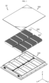
- FIG. 1 is an exploded perspective view showing a battery pack according to the present disclosure.
- FIG. 2 is a perspective view showing the appearance of a battery pack according to the present disclosure.
- FIG. 3 is a diagram showing the inner space of a pack housing included in the battery pack according to the present disclosure.
- the battery pack 10 includes a pack housing 100, a first battery module 210, a second battery module 220, and a pack cover 300.
- the pack housing 100 may include a first accommodation space 110, a second accommodation space 120 spaced apart from the first accommodation space 110, and a center space 130 formed between the first accommodation space 110 and the second accommodation space 120.
- the first accommodation space 110 may be disposed opposite to the second accommodation space 120 with the center space 130 interposed therebetween.
- the pack housing 100 may include five plates without one side in the form of a rectangular parallelepiped. At this time, at least some of the individual plates constituting the pack housing 100 may be integrated with each other. Alternatively, the five plates may be separately manufactured and then coupled to each other through welding or bolting.
- the pack housing 100 may include, for example, a metal material such as aluminum. However, the present disclosure does not limit the pack housing 100 to a specific material.
- At least one first battery module 210 may be disposed within the first accommodation space 110.
- At least one second battery module 220 may be disposed within the second accommodation space 120.
- four first battery modules 210 may be provided in the first accommodation space 110, and four second battery modules 220 may be provided in the second accommodation space 120.
- the pack cover 300 may be configured to cover the battery module 200 by combining with the pack housing 100.
- FIG. 4 is a diagram showing a battery module included in the battery pack according to the present disclosure.
- the battery module 200 may include a battery cell 201.
- the battery cell 201 may be provided in plurality.
- the battery cell 201 may mean a secondary battery.
- the battery cell 201 may include an electrode assembly, an electrolyte, a battery case accommodating the electrode assembly and the electrolyte, and a pair of electrode leads connected to the electrode assembly and drawn out of the battery case.
- the battery cell 201 may be, for example, a pouch-type secondary battery. However, other types of secondary batteries, such as a cylindrical battery or prismatic battery, may also be employed as the battery cell 201 of the present disclosure.
- the battery module 200 may further include a bus bar frame assembly 202 for electrically connecting the plurality of battery cells 201 to each other.
- the bus bar frame assembly 202 may be provided in a pair, for example. In this case, the pair of bus bar frame assemblies 202 may be coupled to one side and the other side of the longitudinal direction (direction parallel to the X-axis) of the battery cell 201, respectively.
- FIG. 5 is a diagram showing a battery module included in the battery pack according to the present disclosure.
- the battery module 200 may further include a module case 203.
- the module case 203 may be configured to accommodate at least one battery cell 201.
- the module case 203 may include a venting hole 203a. When a gas is generated from the battery cell 201 accommodated in the inner space, the venting hole 203a may be configured to discharge the generated gas from the inside of the module case 203 to the outside.
- FIG. 6 is a diagram showing a pack cover included in the battery pack according to the present disclosure.
- FIG. 7 is a cross-sectional view taken along line B-B' in FIG. 6 .
- FIG. 8 is a cross-sectional view taken along line C-C' in FIG. 6 .
- the pack cover 300 may include a first side venting channel 310, a second side venting channel 320, and a center venting channel 330.
- the first side venting channel 310 may be configured to guide gas generated from the first battery module 210 to the center space 130 at a position corresponding to the first battery module 210.
- the first side venting channel 310 may have a substantially trapezoidal shape when viewed on the Y-Z plane.
- the first side venting channel 310 may be extended in the X-axis direction.
- the first side venting channel 310 may be a groove formed on one surface of the pack cover 300 (a surface parallel to the X-Y plane).
- the first side venting channel 310 may have a first volume. Referring to FIG. 1 together, the first volume may be the volume of a space between the inner side of the pack cover 300 and the first battery module 210 positioned to be in close contact with the pack cover 300.
- the volume of the first side venting channel 310 corresponding to one battery module may be the first volume.
- the volume of an individual channel may be the first volume.
- the second side venting channel 320 may be configured to guide the gas generated in the second battery module 220 to the center space 130 at a position corresponding to the second battery module 220.
- the second side venting channel 320 may have a substantially trapezoidal shape when viewed on the Y-Z plane.
- the second side venting channel 320 may be extended in the X-axis direction.
- the second side venting channel 320 may be a groove formed on one surface of the pack cover 300 (a surface parallel to the X-Y plane).
- the second side venting channel 320 may have a second volume. Referring to FIG.
- the second volume may be the volume of a space between the inner side of the pack cover 300 and the second battery module 220 located in close contact with the pack cover 300.
- the volume of the second side venting channel 320 corresponding to one battery module may be the second volume.
- the volume of an individual channel may be the second volume.
- the center venting channel 330 may be configured to guide the gas collected in the center space 130 to the outside of the pack housing 100 at a position corresponding to the center space 130.
- the center venting channel 330 may be extended in the Y-axis direction with a width corresponding to the center space 130 and a height corresponding to the first side venting channel 310 and the second side venting channel 320 on the X-Z plane.
- the center venting channel 330 may have a third volume equal to or greater than the first volume and the second volume.
- a function of controlling gas flow can be added by creating a venting channel in the pack cover 300, which is used only for covering the general pack housing 100.
- gas and flame generated from each battery module move to the center venting channel 330 through the first side venting channel 310 and the second side venting channel 320, so the temperature of the gas may drop during movement, and the intensity of the flame may be weakened. It is possible to eliminate or reduce the damage that can be caused by high-temperature gas and flame being ejected to the outside.
- center venting channel 330 has the same or greater volume than the side venting channels 310 and 320, gas can smoothly move from the side venting channels 310 and 320 to the center venting channel 330, and it is possible to prevent the gas entering the center venting channel 330 from flowing back to the side venting channel. Therefore, it is possible to smoothly discharge the gas.
- FIG. 9 is a diagram showing a pack cover included in the battery pack according to the present disclosure.
- a region of the pack cover 300 corresponding to the center venting channel 330 may be formed at a higher position than a region corresponding to the first side venting channel 310 and the second side venting channel 320.
- the pack cover 300 may have a shape in which only a region corresponding to the center venting channel 330 protrudes in the positive direction of the Z axis. In the protruding shape, the inner surface of the pack cover 300 may be indented to form a certain space therein.
- the volume of the center venting channel 330 larger than the volume of the side venting channel.
- the protruding part of the pack cover 300 is located between the driver's seat and the front passenger's seat and/or in the middle of the rear seat of the vehicle, so it is easy to mount the battery pack 10.
- FIG. 10 is a diagram showing a barrier and an additional barrier included in the battery pack according to the present disclosure.
- the battery pack 10 may include a barrier 140 and an additional barrier 141.
- the barrier 140 may be disposed at a corresponding position between the first battery module 210 adjacent to each other and at a corresponding position between the second battery module 220 adjacent to each other, respectively.
- the barrier 140 may be configured to block the movement of gas between the accommodation spaces of the first battery modules 210 adjacent to each other and the movement of gas between the accommodation spaces of the second battery modules 220 adjacent to each other.
- the barrier 140 may be coupled with the pack cover 300 and/or the pack housing 100. The coupling may be performed by welding or bolting.
- the barrier 140 may have an approximate beam shape with an empty inside.
- the accommodation spaces of the first battery module 210 adjacent to each other and the accommodation spaces of the second battery module 220 adjacent to each other are structurally isolated from each other by the barrier 140, so that the gas generated in each battery module does not move toward an adjacent battery module, but moves only in a direction toward the sensor space through the first side venting channel 310 and the second side venting channel 320.
- the temperature of the gas may be lowered and the intensity of the flame may be weakened, thereby minimizing the effect of high-temperature flame and gas generated in each battery module on other battery modules.
- the barrier 140 has an approximate beam shape with an empty inner space, the weight can be reduced while maintaining rigidity.
- the empty space formed in the barrier 140 can be used as a space for accommodating electrical components required for the battery module. Electrical equipment can be protected from physical impact by the barrier 140.
- the additional barrier 141 may have a long extension shape along the extension direction (parallel to the Y-axis) of the center venting channel 330 in order to define the accommodation space of the first battery module 210. Accordingly, the accommodation space for the first battery module 210 may be formed by the pack housing 100 and the additional barrier 141. Similarly, the additional barrier 141 for defining the accommodation space of the second battery module 220 may have a long extension shape along the extension direction (parallel to the Y-axis) of the center venting channel 330, that is, along the longitudinal direction of the battery pack 10. Accordingly, the accommodation space for the second battery module 220 may be formed by the pack housing 100 and the additional barrier 141.
- the additional barrier 141 for defining the accommodation space of the first battery module 210 and the additional barrier 141 for defining the accommodation space of the second battery module 220 may be spaced apart from each other to form a center space 130 therebetween.
- the additional barrier 141 may be configured to function as a common barrier 140 for defining the accommodation space of the first battery module 210 and the accommodation space of the second battery module 220 within the pack housing 100.
- the additional barrier 141 may have a long extension shape along the extension direction of the center venting channel 330. This additional barrier 141 may be located approximately at the center of the pack housing 100 in the width direction (direction parallel to the X-axis).
- the additional barrier 141 may have an empty space therein, thereby reducing weight while maintaining rigidity.
- the empty space formed in the additional barrier 141 may be used as a passage through which wires connecting the battery modules 200 pass.
- the wires can be protected from physical impact by the additional barrier 141. Therefore, a secondary battery in which energy density is important can have a high energy density.
- the barrier 140 and the additional barrier 141 may be configured to be at least partially integrated with each other. Alternatively, these members may be manufactured separately and then coupled to each other through welding or bolting.
- FIG. 11 is a cross-sectional view taken along line A-A' in FIG. 2 .
- the battery pack 10 may include a sealing member 150.
- the sealing member 150 may be provided on at least one position between the barrier 140 and the pack cover 300 and between the barrier 140 and the pack housing 100.
- the sealing member 150 may be provided not only on the barrier 140 but also on at least one position between the additional barrier 141 and the pack cover 300 and between the additional barrier 141 and the pack housing 100.
- the sealing member 150 may be configured to cover at least a part of the coupling portion of the barrier 140, the pack cover 300, and/or the pack housing 100.
- an effect of preventing gas from moving into the gap between the barrier 140 and the pack cover 300 and/or the pack housing 100 can be further improved.
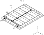
- FIG. 12 is a diagram showing a gas collection space and a venting device included in the battery pack according to the present disclosure.
- the pack housing 100 may include a gas collection space 160.
- the gas collection space 160 may be formed in at least one of one side and the other side along the extension direction of the center venting channel 330.
- the gas collection space 160 may communicate with the center venting channel 330.
- the gas collection space 160 may be provided at the end of the longitudinal direction (direction parallel to the Y-axis) of the pack housing 100 parallel to the extension direction of the center venting.
- the present disclosure is not limited to the shape, location, and number of gas collection spaces 160 shown in FIG. 12 .
- the pack housing 100 may include a venting device 170.
- the venting device 170 may be configured to discharge the gas in the gas collection space 160 to the outside of the pack housing 100.
- the venting device 170 is formed to penetrate the pack housing 100 and may be in the form of a simple hole.
- the venting device 700 may be a specific device that not only has a completely open form, but also has a form not completely open, that is closed in a normal state and is opened according to a change in pressure or temperature.
- the internal pressure of the battery pack 10 when the internal pressure of the battery pack 10 increases since a large amount of gas is generated at once, the internal pressure of the battery pack 10 may be quickly reduced through the gas collection space 160.
- the gas may be discharged in the intended direction through the venting device 170, and even if a lot of venting gas is instantaneously generated, the gas may be discharged more rapidly and smoothly by increasing the processing capacity or number of the venting device 170.
- FIG. 13 is a diagram showing a cover plate and a channel plate included in the battery pack according to the present disclosure.
- the pack cover 300 may include a cover plate 340 and a channel plate 350.
- the cover plate 340 may be configured to cover the accommodation space of the pack housing 100.
- the channel plate 350 is coupled to the inner surface of the cover plate 340 and may include a first side venting channel 310, a second side venting channel 320, and a center venting channel 330.
- the channel plate 350 may include a first channel plate 351, a second channel plate 352, and a third channel plate 353.
- the first channel plate 351 may be coupled to the inner surface of the cover plate 340 at a position corresponding to the first battery module 210.
- the first channel plate 351 may include a first side venting channel 310.
- the second channel plate 352 may be coupled to the inner surface of the cover plate 340 at a position corresponding to the second battery module 220.
- the second channel plate 352 may include a second side venting channel 320.
- the third channel plate 353 may be coupled at a position corresponding to the center space 130.
- the third channel plate 353 may include a center venting channel 330.
- At least some of the cover plate 340, the first channel plate 351, the second channel plate 352, and the third channel plate 353 may be integrated with each other, and the present disclosure is not limited to the case where these plates are manufactured separately and combined.
- the pack cover 300 in a general form without a channel can be utilized as it is.
- production efficiency can be increased by separately manufacturing and combining plates.
- the venting channel is formed on the inner surface of the pack cover 300, it is possible to minimize the decrease in the accommodation space in the pack housing 100 due to the formation of the channel.
- FIG. 14 is a diagram showing a groove provided in a pack cover included in the battery pack according to the present disclosure.
- the first side venting channel 310 and the second side venting channel 320 may have a groove form G formed on the inner surface of the pack cover 300.
- the first side venting channel 310 and the second side venting channel 320 may have a groove form G formed on the inner surface of the channel plate 350.
- the surface of the channel plate 350 opposite to the surface on which the groove G is formed may be coupled to the inner surface of the cover plate 340.
- the first side venting channel 310 and the second side venting channel 320 may be provided in plurality along the longitudinal direction (Y-axis extension direction) of the battery pack 10. To this end, a plurality of grooves G may be provided.
- space efficiency can be increased in a secondary battery where energy density is important because a groove is formed without a separate member for forming a venting channel on the inner surface of the pack cover 300 or the channel plate 350.
- Production is easy because the present disclosure can be implemented more easily than combining a separate member for forming a venting channel with the pack cover 300 or the channel plate 350.
- FIG. 15 is a cross-sectional view showing the battery pack according to the present disclosure to which the pack cover of FIG. 13 is applied, taken along line D-D'.
- the center venting channel 330 may include a first center venting channel 331 and a second center venting channel 332.
- the first center venting channel 331 may communicate with the first side venting channel 310.
- the first center venting channel 331 may have a substantially rectangular shape when viewed on an X-Z plane.
- the first center venting channel 331 may be extended in the Y-axis direction.
- the first center venting channel 331 may have a fourth volume larger than the first volume.
- the second center venting channel 332 may communicate with the second side venting channel 320.
- the second center venting channel 332 may have a substantially rectangular shape when viewed on an X-Z plane.
- the second center venting channel 332 may be extended in the Y-axis direction.
- the second center venting channel 332 may have a fifth volume larger than the second volume.
- the third channel plate 353 may include a first channel forming portion 353a, a second channel forming portion 353b, and a coupling portion 353c.
- the first channel forming portion 353a may form a first center venting channel 331 communicating with the first side venting channel 310.
- the second channel forming portion 353b may form a second center venting channel 332 communicating with the second side venting channel 320.
- the coupling portion 353c may connect the first channel forming portion 353a and the second channel forming portion 353b.
- the coupling portion 353c may be coupled to the inner surface of the cover plate 340.
- the third channel plate 353 may have a long extension shape along the Y-axis extension direction.
- the first channel forming portion 353a may be spaced apart from the inner surface of the cover plate 340 by a predetermined distance. Accordingly, the first center venting channel 331 may be formed in a space surrounded by the first channel forming portion 353a, the cover plate 340, and the coupling portion 353c. Similarly, the second channel forming portion 353b may be positioned apart from the inner surface of the cover plate 340 by a predetermined distance. Accordingly, the second center venting channel 332 may be formed in a space surrounded by the second channel forming portion 353b, the cover plate 340, and the coupling portion 353c.
- the first channel forming portion 353a can be located at a height (length extending along the direction parallel to the Z-axis) corresponding to the height of the battery cell 201 standing upright in the pack housing 100.
- the second channel forming portion 353b can be located at a height corresponding to the height (length extending along the direction parallel to the Z-axis) of the battery cell 201 standing upright in the pack housing 100.
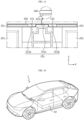
- FIG. 16 is a diagram showing a vehicle according to the present disclosure.
- the battery pack 10 according to the present disclosure may be applied to a vehicle 1 such as an electric vehicle or a hybrid vehicle. That is, the vehicle 1 according to the present disclosure may include the battery pack 10 according to the present disclosure. In addition, the vehicle 1 according to the present disclosure may further include various other components included in a vehicle 1 in addition to the battery pack 10. For example, the vehicle 1 according to the present disclosure may further include a vehicle body, a motor, and a control device such as an electronic control unit (ECU), in addition to the battery pack 10 according to the present disclosure.
- ECU electronice control unit
Landscapes
- Chemical & Material Sciences (AREA)
- Chemical Kinetics & Catalysis (AREA)
- Electrochemistry (AREA)
- General Chemical & Material Sciences (AREA)
- Engineering & Computer Science (AREA)
- Aviation & Aerospace Engineering (AREA)
- Manufacturing & Machinery (AREA)
- Battery Mounting, Suspending (AREA)
- Gas Exhaust Devices For Batteries (AREA)
Abstract
Description
- The present disclosure relates to a battery pack and a vehicle including the same, and more specifically, to a battery pack configured to discharge a high-temperature gas to the outside of the battery pack without affecting other adjacent battery modules when the gas is generated inside the battery module, and a vehicle including the same.
- The present application claims priority to
Korean Patent Application No. 10-2022-0028947 filed on March 7, 2022 - As the demand for portable electronic products such as notebooks, video cameras, and mobile phones rapidly increases and the commercialization of robots and electric vehicles begins in earnest, research on high-performance secondary batteries capable of repeated charging and discharging is being actively conducted.
- Currently commercialized secondary batteries include nickel cadmium batteries, nickel hydrogen batteries, nickel zinc batteries, and lithium secondary batteries. Among them, lithium secondary batteries are in the limelight because of their advantages of free charge and discharge, very low self-discharge rate, and high energy density, as the memory effect hardly occurs compared to nickel-based secondary batteries.
- These lithium secondary batteries mainly use lithium-based oxide and carbon material as a positive electrode active material and a negative electrode active material, respectively. A lithium secondary battery includes an electrode assembly in which a positive electrode plate and a negative electrode plate coated with such a positive electrode active material and a negative electrode active material, respectively, are disposed with a separator therebetween, and an exterior material, that is, a battery case for sealing and accommodating the electrode assembly together with electrolyte.
- In general, lithium secondary batteries may be classified into a can-type secondary battery in which an electrode assembly is embedded in a metal can and a pouch-type secondary battery in which an electrode assembly is embedded in a pouch of an aluminum laminate sheet, depending on the shape of the exterior material.
- Recently, secondary batteries have been widely used for driving or energy storage not only in small devices such as portable electronic devices, but also in medium and large-sized devices such as electric vehicles and energy storage systems (ESSs). Many of these secondary batteries may be accommodated together inside a module case in a state of being electrically connected, which may configure one battery module, and such battery modules may be electrically connected again in a narrow space to increase energy density, which configures a battery pack.
- However, when a plurality of battery modules exist in a dense state in a narrow space as above, they may be vulnerable to accidents such as fire or explosion. For example, when an event such as thermal runaway occurs in one battery module, high-temperature gas may be discharged from the battery module. If this gas is not properly discharged to the outside of the battery pack, the thermal event generated in some battery modules may be propagated to other battery modules provided inside the battery pack, which may cause a chain reaction. Also, in this case, the pressure inside the battery pack increases, and there is a possibility of explosion. When the battery pack explodes, not only great damage may be caused to nearby devices or users due to the pressure of the explosion, but also the range and speed of damage may be further increased. Therefore, it is required to develop a battery pack having a structure that allows the high-temperature gas to be safely discharged to the outside of the battery pack without affecting other adjacent battery modules when an abnormality occurs in some battery modules and a gas is discharged.
- The present disclosure is designed to solve the problems of the related art, and therefore the present disclosure is directed to controlling the flow of a gas in a desired direction by adding an additional venting channel formation structure to an existing battery pack.
- In another aspect of the present disclosure, the present disclosure is directed to preventing a phenomenon in which gas smoothly moves to a center venting channel through a side venting channel and flows back toward the side venting channel.
- In still another aspect, the present disclosure is directed to allowing the high-temperature gas ejected when a thermal event occurs in some battery modules to be safely discharged to the outside of the battery pack without affecting other battery modules inside the battery pack.
- In one aspect of the present disclosure, there is provided a battery pack comprising: a pack housing having a first accommodation space, a second accommodation space spaced apart from the first accommodation space, and a center space formed between the first accommodation space and the second accommodation space; at least one first battery module disposed within the first accommodation space; at least one second battery module disposed within the second accommodation space; and a pack cover configured to include a first side venting channel having a first volume and configured to guide the gas generated in the first battery module to the center space at a position corresponding to the first battery module, a second side venting channel having a second volume and configured to guide the gas generated in the second battery module to the center space at a position corresponding to the second battery module, and a center venting channel having a third volume equal to or greater than the first volume and the second volume and configured to guide the gas collected in the center space to the outside of the pack housing at a position corresponding to the center space.
- A region of the pack cover corresponding to the center venting channel may be formed at a higher position than a region corresponding to the first side venting channel and the second side venting channel.
- The battery pack may include a barrier disposed at a corresponding position between the first battery modules adjacent to each other and a corresponding position between the second battery modules adjacent to each other, respectively.
- The barrier may be configured to block the movement of gas between the accommodation spaces of the first battery modules adjacent to each other and the movement of gas between the accommodation spaces of the second battery modules adjacent to each other.
- The battery pack may include a sealing member on at least one position between the barrier and the pack cover and between the barrier and the pack housing.
- The pack cover may include a cover plate configured to cover the accommodation space of the pack housing; and a channel plate coupled to an inner surface of the cover plate and having the first side venting channel, the second side venting channel, and the center venting channel.
- The channel plate may include a first channel plate coupled to the inner surface of the cover plate at a position corresponding to the first battery module and having the first side venting channel; a second channel plate coupled to the inner surface of the cover plate at a position corresponding to the second battery module and having the second side venting channel; and a third channel plate coupled to the inner surface of the cover plate at a position corresponding to the center space and having the center venting channel.
- The pack housing may include a gas collection space formed in at least one of one side and the other side along an extension direction of the center venting channel.
- The pack housing may include a venting device configured to allow gas in the gas collection space to be discharged to the outside of the pack housing.
- The first side venting channel and the second side venting channel may have a groove form formed on an inner surface of the pack cover.
- The first side venting channel and the second side venting channel may have a groove form formed on one surface of the first channel plate and the second channel plate, respectively, and a surface of the first channel plate and the second channel plate opposite to a surface on which the groove is formed may be coupled to the inner surface of the cover plate.
- The first side venting channel and the second side venting channel may be provided in plurality along a longitudinal direction of the battery pack, respectively.
- The center venting channel may include a first center venting channel communicating with the first side venting channel and configured to have a fourth volume larger than the first volume; and a second center venting channel communicating with the second side venting channel and configured to have a fifth volume greater than the second volume.
- The third channel plate may include a first channel forming portion forming a first center venting channel communicating with the first side venting channel; a second channel forming portion forming a second center venting channel communicating with the second side venting channel; and a coupling portion that connects the first channel forming portion and the second channel forming portion and is coupled to the inner surface of the cover plate.
- A vehicle according to an embodiment of the present disclosure for achieving the above object includes the battery pack according to the present disclosure.
- According to one aspect of the present disclosure, a function of controlling a gas flow may be added by creating a venting channel in a pack cover that is used only to cover a general pack housing. When a thermal event occurs, the temperature of the gas and flame generated in each battery module may drop during movement, and the intensity of the flame may be weakened, and it is possible to eliminate or reduce the damage that can be caused by high-temperature gas and flame being ejected to the outside.
- In particular, due to the structure of the pack cover having a side venting channel with a smaller volume than the center venting channel, gas can move smoothly from the side venting channel to the center venting channel, and it is possible to prevent the phenomenon in which the gas entering the center venting channel flows back to the side venting channel. Therefore, it is possible to smoothly discharge the gas.
- According to another aspect of the present disclosure, it is easy to make the volume of the center venting channel larger than the volume of the side venting channel. When a battery pack including a pack cover with a protruding center area is mounted on a vehicle, the protruding part of the pack cover is located between the driver's seat and the front passenger's seat and/or in the middle of the rear seat of the vehicle, so that the battery pack can be easily mounted.
- According to another aspect of the present disclosure, it is possible to delay/prevent the high-temperature venting gas generated from some problematic battery modules from affecting neighboring battery modules during a thermal event.
- According to another aspect of the present disclosure, the release of gas can be done quickly.
- According to another aspect of the present disclosure, fire can be prevented or the rate of fire spread can be delayed.
- According to another aspect of the present disclosure, in a secondary battery where energy density is important, it is possible to protect the secondary battery from external physical impact while arranging the secondary battery without providing a separate space for electrical components required for a battery module.
- In addition, the present disclosure may have various other effects, which will be described in each embodiment, or descriptions of effects that can be easily inferred by those skilled in the art will be omitted.
- The accompanying drawings illustrate a preferred embodiment of the present disclosure and together with the foregoing disclosure, serve to provide further understanding of the technical features of the present disclosure, and thus, the present disclosure is not construed as being limited to the drawing.
-
FIG. 1 is an exploded perspective view showing a battery pack according to the present disclosure. -
FIG. 2 is a perspective view showing the appearance of a battery pack according to the present disclosure. -
FIG. 3 is a diagram showing the inner space of a pack housing included in the battery pack according to the present disclosure. -
FIGS. 4 and5 are diagrams showing a battery module included in the battery pack according to the present disclosure. -
FIG. 6 is a diagram showing a pack cover included in the battery pack according to the present disclosure. -
FIG. 7 is a cross-sectional view taken along line B-B' inFIG. 6 . -
FIG. 8 is a cross-sectional view taken along line C-C' inFIG. 6 . -
FIG. 9 is a diagram showing a pack cover included in the battery pack according to the present disclosure. -
FIG. 10 is a diagram showing a barrier included in the battery pack according to the present disclosure. -
FIG. 11 is a cross-sectional view taken along line A-A' inFIG. 2 . -
FIG. 12 is a diagram showing a collection space and a venting hole included in the battery pack according to the present disclosure. -
FIG. 13 is a diagram showing a cover plate and a channel plate included in the battery pack according to the present disclosure. -
FIG. 14 is a diagram showing a groove provided in a pack cover included in the battery pack according to the present disclosure. -
FIG. 15 is a cross-sectional view showing the battery pack according to the present disclosure to which the pack cover ofFIG. 13 is applied, taken along line D-D'. -
FIG. 16 is a diagram showing a vehicle according to the present disclosure. - Hereinafter, preferred embodiments of the present disclosure will be described in detail with reference to the accompanying drawings. The accompanying drawings illustrate a preferred embodiment of the present disclosure and together with the foregoing disclosure, serve to provide further understanding of the technical features of the present disclosure, and thus, the present disclosure is not construed as being limited to the drawing. Like reference signs designate like components. Also, in the drawings, the thickness, ratio, and dimensions of components may be exaggerated for effective description of technical content.
- It should be understood that the terms used in the specification and the appended claims should not be construed as limited to general and dictionary meanings, but interpreted based on the meanings and concepts corresponding to technical aspects of the present disclosure on the basis of the principle that the inventor is allowed to define terms appropriately for the best explanation.
- In this specification, terms indicating directions such as up, down, left, right, front, and back are used, but these terms are only for convenience of explanation, and it is apparent to those skilled in the art that the terms may vary depending on the location of the target object or the location of the observer.
- Therefore, the description proposed herein is just a preferable example for the purpose of illustrations only, not intended to limit the scope of the disclosure, so it should be understood that other equivalents and modifications could be made thereto without departing from the scope of the disclosure.
-
FIG. 1 is an exploded perspective view showing a battery pack according to the present disclosure.FIG. 2 is a perspective view showing the appearance of a battery pack according to the present disclosure.FIG. 3 is a diagram showing the inner space of a pack housing included in the battery pack according to the present disclosure. - Referring to
FIGS. 1 to 3 , thebattery pack 10 according to the present disclosure includes apack housing 100, afirst battery module 210, asecond battery module 220, and apack cover 300. - The
pack housing 100 may include afirst accommodation space 110, asecond accommodation space 120 spaced apart from thefirst accommodation space 110, and acenter space 130 formed between thefirst accommodation space 110 and thesecond accommodation space 120. Thefirst accommodation space 110 may be disposed opposite to thesecond accommodation space 120 with thecenter space 130 interposed therebetween. Thepack housing 100 may include five plates without one side in the form of a rectangular parallelepiped. At this time, at least some of the individual plates constituting thepack housing 100 may be integrated with each other. Alternatively, the five plates may be separately manufactured and then coupled to each other through welding or bolting. Thepack housing 100 may include, for example, a metal material such as aluminum. However, the present disclosure does not limit thepack housing 100 to a specific material. - At least one
first battery module 210 may be disposed within thefirst accommodation space 110. At least onesecond battery module 220 may be disposed within thesecond accommodation space 120. For example, as shown inFIG. 1 , fourfirst battery modules 210 may be provided in thefirst accommodation space 110, and foursecond battery modules 220 may be provided in thesecond accommodation space 120. - The
pack cover 300 may be configured to cover thebattery module 200 by combining with thepack housing 100. -
FIG. 4 is a diagram showing a battery module included in the battery pack according to the present disclosure. - Referring to
FIG. 4 , thebattery module 200 may include abattery cell 201. Thebattery cell 201 may be provided in plurality. Thebattery cell 201 may mean a secondary battery. Thebattery cell 201 may include an electrode assembly, an electrolyte, a battery case accommodating the electrode assembly and the electrolyte, and a pair of electrode leads connected to the electrode assembly and drawn out of the battery case. Thebattery cell 201 may be, for example, a pouch-type secondary battery. However, other types of secondary batteries, such as a cylindrical battery or prismatic battery, may also be employed as thebattery cell 201 of the present disclosure. - When the
battery cell 201 is provided in plurality, the plurality ofbattery cells 201 may be electrically connected. Thebattery module 200 may further include a busbar frame assembly 202 for electrically connecting the plurality ofbattery cells 201 to each other. The busbar frame assembly 202 may be provided in a pair, for example. In this case, the pair of busbar frame assemblies 202 may be coupled to one side and the other side of the longitudinal direction (direction parallel to the X-axis) of thebattery cell 201, respectively. -
FIG. 5 is a diagram showing a battery module included in the battery pack according to the present disclosure. - The
battery module 200 may further include amodule case 203. Themodule case 203 may be configured to accommodate at least onebattery cell 201. Themodule case 203 may include aventing hole 203a. When a gas is generated from thebattery cell 201 accommodated in the inner space, theventing hole 203a may be configured to discharge the generated gas from the inside of themodule case 203 to the outside. -
FIG. 6 is a diagram showing a pack cover included in the battery pack according to the present disclosure.FIG. 7 is a cross-sectional view taken along line B-B' inFIG. 6 .FIG. 8 is a cross-sectional view taken along line C-C' inFIG. 6 . - Referring to
FIGS. 6 to 8 , thepack cover 300 may include a firstside venting channel 310, a secondside venting channel 320, and acenter venting channel 330. - The first
side venting channel 310 may be configured to guide gas generated from thefirst battery module 210 to thecenter space 130 at a position corresponding to thefirst battery module 210. The firstside venting channel 310 may have a substantially trapezoidal shape when viewed on the Y-Z plane. The firstside venting channel 310 may be extended in the X-axis direction. The firstside venting channel 310 may be a groove formed on one surface of the pack cover 300 (a surface parallel to the X-Y plane). The firstside venting channel 310 may have a first volume. Referring toFIG. 1 together, the first volume may be the volume of a space between the inner side of thepack cover 300 and thefirst battery module 210 positioned to be in close contact with thepack cover 300. When a plurality offirst battery modules 210 are provided, the volume of the firstside venting channel 310 corresponding to one battery module may be the first volume. When a plurality of firstside venting channels 310 are provided, the volume of an individual channel may be the first volume. - If the description of
FIG. 7 and the firstside venting channel 310 is applied to the secondside venting channel 320, the secondside venting channel 320 may be configured to guide the gas generated in thesecond battery module 220 to thecenter space 130 at a position corresponding to thesecond battery module 220. The secondside venting channel 320 may have a substantially trapezoidal shape when viewed on the Y-Z plane. The secondside venting channel 320 may be extended in the X-axis direction. The secondside venting channel 320 may be a groove formed on one surface of the pack cover 300 (a surface parallel to the X-Y plane). The secondside venting channel 320 may have a second volume. Referring toFIG. 1 together, the second volume may be the volume of a space between the inner side of thepack cover 300 and thesecond battery module 220 located in close contact with thepack cover 300. When a plurality ofsecond battery modules 220 are provided, the volume of the secondside venting channel 320 corresponding to one battery module may be the second volume. When a plurality of secondside venting channels 320 are provided, the volume of an individual channel may be the second volume. - Referring to
FIGS. 6 to 8 together withFIG. 3 , thecenter venting channel 330 may be configured to guide the gas collected in thecenter space 130 to the outside of thepack housing 100 at a position corresponding to thecenter space 130. Thecenter venting channel 330 may be extended in the Y-axis direction with a width corresponding to thecenter space 130 and a height corresponding to the firstside venting channel 310 and the secondside venting channel 320 on the X-Z plane. Thecenter venting channel 330 may have a third volume equal to or greater than the first volume and the second volume. - According to this configuration of the present disclosure, a function of controlling gas flow can be added by creating a venting channel in the
pack cover 300, which is used only for covering thegeneral pack housing 100. When a thermal event occurs, gas and flame generated from each battery module move to thecenter venting channel 330 through the firstside venting channel 310 and the secondside venting channel 320, so the temperature of the gas may drop during movement, and the intensity of the flame may be weakened. It is possible to eliminate or reduce the damage that can be caused by high-temperature gas and flame being ejected to the outside. - In particular, when the
center venting channel 330 has the same or greater volume than theside venting channels side venting channels center venting channel 330, and it is possible to prevent the gas entering thecenter venting channel 330 from flowing back to the side venting channel. Therefore, it is possible to smoothly discharge the gas. -
FIG. 9 is a diagram showing a pack cover included in the battery pack according to the present disclosure. - Referring to
FIG. 9 , a region of thepack cover 300 corresponding to thecenter venting channel 330 may be formed at a higher position than a region corresponding to the firstside venting channel 310 and the secondside venting channel 320. Thepack cover 300 may have a shape in which only a region corresponding to thecenter venting channel 330 protrudes in the positive direction of the Z axis. In the protruding shape, the inner surface of thepack cover 300 may be indented to form a certain space therein. - According to this configuration of the present disclosure, it is easy to make the volume of the
center venting channel 330 larger than the volume of the side venting channel. In addition, when thebattery pack 10 including thepack cover 300 is mounted on a vehicle, the protruding part of thepack cover 300 is located between the driver's seat and the front passenger's seat and/or in the middle of the rear seat of the vehicle, so it is easy to mount thebattery pack 10. -
FIG. 10 is a diagram showing a barrier and an additional barrier included in the battery pack according to the present disclosure. - Referring to
FIG. 10 , thebattery pack 10 according to the present disclosure may include abarrier 140 and anadditional barrier 141. Thebarrier 140 may be disposed at a corresponding position between thefirst battery module 210 adjacent to each other and at a corresponding position between thesecond battery module 220 adjacent to each other, respectively. Thebarrier 140 may be configured to block the movement of gas between the accommodation spaces of thefirst battery modules 210 adjacent to each other and the movement of gas between the accommodation spaces of thesecond battery modules 220 adjacent to each other. Thebarrier 140 may be coupled with thepack cover 300 and/or thepack housing 100. The coupling may be performed by welding or bolting. Thebarrier 140 may have an approximate beam shape with an empty inside. - According to this configuration of the present disclosure, the accommodation spaces of the
first battery module 210 adjacent to each other and the accommodation spaces of thesecond battery module 220 adjacent to each other are structurally isolated from each other by thebarrier 140, so that the gas generated in each battery module does not move toward an adjacent battery module, but moves only in a direction toward the sensor space through the firstside venting channel 310 and the secondside venting channel 320. During this movement, the temperature of the gas may be lowered and the intensity of the flame may be weakened, thereby minimizing the effect of high-temperature flame and gas generated in each battery module on other battery modules. On the other hand, when thebarrier 140 has an approximate beam shape with an empty inner space, the weight can be reduced while maintaining rigidity. The empty space formed in thebarrier 140 can be used as a space for accommodating electrical components required for the battery module. Electrical equipment can be protected from physical impact by thebarrier 140. - Referring again to
FIG. 10 together withFIG. 3 , theadditional barrier 141 may have a long extension shape along the extension direction (parallel to the Y-axis) of thecenter venting channel 330 in order to define the accommodation space of thefirst battery module 210. Accordingly, the accommodation space for thefirst battery module 210 may be formed by thepack housing 100 and theadditional barrier 141. Similarly, theadditional barrier 141 for defining the accommodation space of thesecond battery module 220 may have a long extension shape along the extension direction (parallel to the Y-axis) of thecenter venting channel 330, that is, along the longitudinal direction of thebattery pack 10. Accordingly, the accommodation space for thesecond battery module 220 may be formed by thepack housing 100 and theadditional barrier 141. As such, when theadditional barrier 141 for defining the accommodation space of thefirst battery module 210 and theadditional barrier 141 for defining the accommodation space of thesecond battery module 220 are separately provided, theadditional barrier 141 for defining the accommodation space of thefirst battery module 210 and theadditional barrier 141 for defining the accommodation space of thesecond battery module 220 may be spaced apart from each other to form acenter space 130 therebetween. Meanwhile, theadditional barrier 141 may be configured to function as acommon barrier 140 for defining the accommodation space of thefirst battery module 210 and the accommodation space of thesecond battery module 220 within thepack housing 100. Theadditional barrier 141 may have a long extension shape along the extension direction of thecenter venting channel 330. Thisadditional barrier 141 may be located approximately at the center of thepack housing 100 in the width direction (direction parallel to the X-axis). - The
additional barrier 141 may have an empty space therein, thereby reducing weight while maintaining rigidity. The empty space formed in theadditional barrier 141 may be used as a passage through which wires connecting thebattery modules 200 pass. In addition, the wires can be protected from physical impact by theadditional barrier 141. Therefore, a secondary battery in which energy density is important can have a high energy density. - The
barrier 140 and theadditional barrier 141 may be configured to be at least partially integrated with each other. Alternatively, these members may be manufactured separately and then coupled to each other through welding or bolting. -
FIG. 11 is a cross-sectional view taken along line A-A' inFIG. 2 . - Referring to
FIG. 11 , thebattery pack 10 according to the present disclosure may include a sealingmember 150. The sealingmember 150 may be provided on at least one position between thebarrier 140 and thepack cover 300 and between thebarrier 140 and thepack housing 100. The sealingmember 150 may be provided not only on thebarrier 140 but also on at least one position between theadditional barrier 141 and thepack cover 300 and between theadditional barrier 141 and thepack housing 100. The sealingmember 150 may be configured to cover at least a part of the coupling portion of thebarrier 140, thepack cover 300, and/or thepack housing 100. - According to this configuration of the present disclosure, an effect of preventing gas from moving into the gap between the
barrier 140 and thepack cover 300 and/or thepack housing 100 can be further improved. -
FIG. 12 is a diagram showing a gas collection space and a venting device included in the battery pack according to the present disclosure. - Referring to
FIG. 12 , thepack housing 100 may include agas collection space 160. Thegas collection space 160 may be formed in at least one of one side and the other side along the extension direction of thecenter venting channel 330. Thegas collection space 160 may communicate with thecenter venting channel 330. For example, thegas collection space 160 may be provided at the end of the longitudinal direction (direction parallel to the Y-axis) of thepack housing 100 parallel to the extension direction of the center venting. However, the present disclosure is not limited to the shape, location, and number ofgas collection spaces 160 shown inFIG. 12 . - Referring to
FIG. 12 , thepack housing 100 may include aventing device 170. Theventing device 170 may be configured to discharge the gas in thegas collection space 160 to the outside of thepack housing 100. Theventing device 170 is formed to penetrate thepack housing 100 and may be in the form of a simple hole. In addition, the venting device 700 may be a specific device that not only has a completely open form, but also has a form not completely open, that is closed in a normal state and is opened according to a change in pressure or temperature. - According to this configuration of the present disclosure, when the internal pressure of the
battery pack 10 increases since a large amount of gas is generated at once, the internal pressure of thebattery pack 10 may be quickly reduced through thegas collection space 160. The gas may be discharged in the intended direction through theventing device 170, and even if a lot of venting gas is instantaneously generated, the gas may be discharged more rapidly and smoothly by increasing the processing capacity or number of theventing device 170. -
FIG. 13 is a diagram showing a cover plate and a channel plate included in the battery pack according to the present disclosure. - Referring to
FIG. 13 , thepack cover 300 may include acover plate 340 and achannel plate 350. Thecover plate 340 may be configured to cover the accommodation space of thepack housing 100. Thechannel plate 350 is coupled to the inner surface of thecover plate 340 and may include a firstside venting channel 310, a secondside venting channel 320, and acenter venting channel 330. - The
channel plate 350 may include afirst channel plate 351, asecond channel plate 352, and athird channel plate 353. Thefirst channel plate 351 may be coupled to the inner surface of thecover plate 340 at a position corresponding to thefirst battery module 210. Thefirst channel plate 351 may include a firstside venting channel 310. Thesecond channel plate 352 may be coupled to the inner surface of thecover plate 340 at a position corresponding to thesecond battery module 220. Thesecond channel plate 352 may include a secondside venting channel 320. Thethird channel plate 353 may be coupled at a position corresponding to thecenter space 130. Thethird channel plate 353 may include acenter venting channel 330. - At least some of the
cover plate 340, thefirst channel plate 351, thesecond channel plate 352, and thethird channel plate 353 may be integrated with each other, and the present disclosure is not limited to the case where these plates are manufactured separately and combined. - According to this configuration of the present disclosure, when the
cover plate 340 and thechannel plate 350 do not have an integrated form and are provided as separate parts and combined, thepack cover 300 in a general form without a channel can be utilized as it is. When manufacturing thepack cover 300, production efficiency can be increased by separately manufacturing and combining plates. On the other hand, as described above, when the venting channel is formed on the inner surface of thepack cover 300, it is possible to minimize the decrease in the accommodation space in thepack housing 100 due to the formation of the channel. -
FIG. 14 is a diagram showing a groove provided in a pack cover included in the battery pack according to the present disclosure. - Referring to
FIG. 14 , the firstside venting channel 310 and the secondside venting channel 320 may have a groove form G formed on the inner surface of thepack cover 300. The firstside venting channel 310 and the secondside venting channel 320 may have a groove form G formed on the inner surface of thechannel plate 350. In this case, the surface of thechannel plate 350 opposite to the surface on which the groove G is formed may be coupled to the inner surface of thecover plate 340. - The first
side venting channel 310 and the secondside venting channel 320 may be provided in plurality along the longitudinal direction (Y-axis extension direction) of thebattery pack 10. To this end, a plurality of grooves G may be provided. - According to this embodiment of the present disclosure, space efficiency can be increased in a secondary battery where energy density is important because a groove is formed without a separate member for forming a venting channel on the inner surface of the
pack cover 300 or thechannel plate 350. Production is easy because the present disclosure can be implemented more easily than combining a separate member for forming a venting channel with thepack cover 300 or thechannel plate 350. -
FIG. 15 is a cross-sectional view showing the battery pack according to the present disclosure to which the pack cover ofFIG. 13 is applied, taken along line D-D'. - Referring to
FIG. 15 together withFIG. 13 , thecenter venting channel 330 may include a firstcenter venting channel 331 and a secondcenter venting channel 332. The firstcenter venting channel 331 may communicate with the firstside venting channel 310. The firstcenter venting channel 331 may have a substantially rectangular shape when viewed on an X-Z plane. The firstcenter venting channel 331 may be extended in the Y-axis direction. The firstcenter venting channel 331 may have a fourth volume larger than the first volume. The secondcenter venting channel 332 may communicate with the secondside venting channel 320. The secondcenter venting channel 332 may have a substantially rectangular shape when viewed on an X-Z plane. The secondcenter venting channel 332 may be extended in the Y-axis direction. The secondcenter venting channel 332 may have a fifth volume larger than the second volume. - Referring to
FIG. 15 together withFIG. 13 , thethird channel plate 353 may include a firstchannel forming portion 353a, a secondchannel forming portion 353b, and acoupling portion 353c. The firstchannel forming portion 353a may form a firstcenter venting channel 331 communicating with the firstside venting channel 310. The secondchannel forming portion 353b may form a secondcenter venting channel 332 communicating with the secondside venting channel 320. Thecoupling portion 353c may connect the firstchannel forming portion 353a and the secondchannel forming portion 353b. Thecoupling portion 353c may be coupled to the inner surface of thecover plate 340. Thethird channel plate 353 may have a long extension shape along the Y-axis extension direction. The firstchannel forming portion 353a may be spaced apart from the inner surface of thecover plate 340 by a predetermined distance. Accordingly, the firstcenter venting channel 331 may be formed in a space surrounded by the firstchannel forming portion 353a, thecover plate 340, and thecoupling portion 353c. Similarly, the secondchannel forming portion 353b may be positioned apart from the inner surface of thecover plate 340 by a predetermined distance. Accordingly, the secondcenter venting channel 332 may be formed in a space surrounded by the secondchannel forming portion 353b, thecover plate 340, and thecoupling portion 353c. For smooth communication between the firstside venting channel 310 and the firstcenter venting channel 331, the firstchannel forming portion 353a can be located at a height (length extending along the direction parallel to the Z-axis) corresponding to the height of thebattery cell 201 standing upright in thepack housing 100. Similarly, for smooth communication between the secondside venting channel 320 and the secondcenter venting channel 332, the secondchannel forming portion 353b can be located at a height corresponding to the height (length extending along the direction parallel to the Z-axis) of thebattery cell 201 standing upright in thepack housing 100. -
FIG. 16 is a diagram showing a vehicle according to the present disclosure. - Referring to
FIG. 16 , thebattery pack 10 according to the present disclosure may be applied to avehicle 1 such as an electric vehicle or a hybrid vehicle. That is, thevehicle 1 according to the present disclosure may include thebattery pack 10 according to the present disclosure. In addition, thevehicle 1 according to the present disclosure may further include various other components included in avehicle 1 in addition to thebattery pack 10. For example, thevehicle 1 according to the present disclosure may further include a vehicle body, a motor, and a control device such as an electronic control unit (ECU), in addition to thebattery pack 10 according to the present disclosure. - As described above, the present disclosure has been described based on preferred embodiments with reference to the accompanying drawings, but it is clear that many various and obvious modifications can be made from this description to those skilled in the art without departing from the scope of the present disclosure. Accordingly, the scope of the present disclosure should be construed by the claims described to include such many modified examples.
-
- 1 :
- vehicle
- 10 :
- battery pack
- 100 :
- pack housing
- 110 :
- first accommodation space
- 120 :
- second accommodation space
- 130 :
- center space
- 140 :
- barrier
- 141 :
- additional barrier
- 150 :
- sealing member
- 160 :
- gas collection space
- 170 :
- venting device
- 200 :
- battery module
- 201 :
- battery cell
- 202 :
- bus bar frame assembly
- 203 :
- module case
- 203a :
- venting hole
- 210 :
- first battery module
- 220 :
- second battery module
- 300 :
- pack cover
- 310 :
- first side venting channel
- 320 :
- second side venting channel
- 330 :
- center venting channel
- 331 :
- first center venting channel
- 332 :
- second center venting channel
- 340 :
- cover plate
- 350 :
- channel plate
- 351 :
- first channel plate
- 352 :
- second channel plate
- 353 :
- third channel plate
- 353a :
- first channel forming portion, 353b : second channel forming portion, 353c : coupling portion
- groove :
- G
Claims (15)
- A battery pack comprising:a pack housing having a first accommodation space, a second accommodation space spaced apart from the first accommodation space, and a center space formed between the first accommodation space and the second accommodation space;at least one first battery module disposed within the first accommodation space;at least one second battery module disposed within the second accommodation space; anda pack cover configured to include a first side venting channel having a first volume and configured to guide the gas generated in the first battery module to the center space at a position corresponding to the first battery module, a second side venting channel having a second volume and configured to guide the gas generated in the second battery module to the center space at a position corresponding to the second battery module, and a center venting channel having a third volume equal to or greater than the first volume and the second volume and configured to guide the gas collected in the center space to the outside of the pack housing at a position corresponding to the center space.
- The battery pack according to claim 1, wherein a region of the pack cover corresponding to the center venting channel is formed at a higher position than a region corresponding to the first side venting channel and the second side venting channel.
- The battery pack according to claim 1, wherein the battery pack includes a barrier disposed at a corresponding position between the first battery modules adjacent to each other and a corresponding position between the second battery modules adjacent to each other, respectively.
- The battery pack according to claim 3, wherein the barrier is configured to block the movement of gas between the accommodation spaces of the first battery modules adjacent to each other and the movement of gas between the accommodation spaces of the second battery modules adjacent to each other.
- The battery pack according to claim 4, wherein the battery pack includes a sealing member on at least one position between the barrier and the pack cover and between the barrier and the pack housing.
- The battery pack according to claim 1, wherein the pack cover includes:a cover plate configured to cover the accommodation space of the pack housing; anda channel plate coupled to an inner surface of the cover plate and having the first side venting channel, the second side venting channel, and the center venting channel.
- The battery pack according to claim 6, wherein the channel plate includes:a first channel plate coupled to the inner surface of the cover plate at a position corresponding to the first battery module and having the first side venting channel;a second channel plate coupled to the inner surface of the cover plate at a position corresponding to the second battery module and having the second side venting channel; anda third channel plate coupled to the inner surface of the cover plate at a position corresponding to the center space and having the center venting channel.
- The battery pack according to claim 1, wherein the pack housing includes a gas collection space formed in at least one of one side and the other side along an extension direction of the center venting channel.
- The battery pack according to claim 8, wherein the pack housing includes a venting device configured to allow gas in the gas collection space to be discharged to the outside of the pack housing.
- The battery pack according to claim 1, wherein the first side venting channel and the second side venting channel have a groove form formed on an inner surface of the pack cover.
- The battery pack according to claim 7, wherein the first side venting channel and the second side venting channel have a groove form formed on one surface of the first channel plate and the second channel plate, respectively, and
wherein a surface of the first channel plate and the second channel plate opposite to a surface on which the groove is formed is coupled to the inner surface of the cover plate. - The battery pack according to claim 1, wherein the first side venting channel and the second side venting channel are provided in plurality along a longitudinal direction of the battery pack, respectively.
- The battery pack according to claim 7, wherein the center venting channel includes:a first center venting channel communicating with the first side venting channel and configured to have a fourth volume larger than the first volume; anda second center venting channel communicating with the second side venting channel and configured to have a fifth volume greater than the second volume.
- The battery pack according to claim 13, wherein the third channel plate includes:a first channel forming portion forming a first center venting channel communicating with the first side venting channel;a second channel forming portion forming a second center venting channel communicating with the second side venting channel; anda coupling portion that connects the first channel forming portion and the second channel forming portion and is coupled to the inner surface of the cover plate.
- A vehicle, comprising the battery pack according to any one of claims 1 to 14.
Applications Claiming Priority (2)
| Application Number | Priority Date | Filing Date | Title |
|---|---|---|---|
| KR20220028947 | 2022-03-07 | ||
| PCT/KR2023/003132 WO2023172049A1 (en) | 2022-03-07 | 2023-03-07 | Battery pack and vehicle comprising same |
Publications (3)
| Publication Number | Publication Date |
|---|---|
| EP4391190A1 true EP4391190A1 (en) | 2024-06-26 |
| EP4391190A4 EP4391190A4 (en) | 2025-07-09 |
| EP4391190B1 EP4391190B1 (en) | 2026-04-29 |
Family
ID=87935499
Family Applications (1)
| Application Number | Title | Priority Date | Filing Date |
|---|---|---|---|
| EP23767150.8A Active EP4391190B1 (en) | 2022-03-07 | 2023-03-07 | Battery pack and vehicle including the same |
Country Status (6)
| Country | Link |
|---|---|
| US (1) | US20250183472A1 (en) |
| EP (1) | EP4391190B1 (en) |
| JP (1) | JP7846773B2 (en) |
| KR (1) | KR102918645B1 (en) |
| CN (1) | CN117642918A (en) |
| WO (1) | WO2023172049A1 (en) |
Cited By (1)
| Publication number | Priority date | Publication date | Assignee | Title |
|---|---|---|---|---|
| EP4675786A1 (en) * | 2024-07-03 | 2026-01-07 | Eve Energy Co., Ltd. | Battery module and automobile |
Families Citing this family (7)
| Publication number | Priority date | Publication date | Assignee | Title |
|---|---|---|---|---|
| KR102911657B1 (en) * | 2023-11-17 | 2026-01-13 | 주식회사 엘지에너지솔루션 | Battery pack and Vehicle including the same |
| WO2025105934A1 (en) * | 2023-11-17 | 2025-05-22 | 주식회사 엘지에너지솔루션 | Battery pack and vehicle including same |
| KR102840487B1 (en) * | 2023-12-13 | 2025-07-29 | 주식회사 엘지에너지솔루션 | Battery pack |
| KR20250150800A (en) * | 2024-04-12 | 2025-10-21 | 주식회사 엘지에너지솔루션 | Battery module, Battery pack and vehicle including the same |
| KR20250157867A (en) * | 2024-04-29 | 2025-11-05 | 주식회사 엘지에너지솔루션 | Battery pack and Vehicle including the same |
| KR20250159942A (en) * | 2024-05-03 | 2025-11-11 | 주식회사 엘지에너지솔루션 | Battery module, Battery pack and vehicle including the same |
| WO2026029484A1 (en) * | 2024-07-31 | 2026-02-05 | 주식회사 엘지에너지솔루션 | Battery pack and vehicle including same |
Family Cites Families (13)
| Publication number | Priority date | Publication date | Assignee | Title |
|---|---|---|---|---|
| JP2009054303A (en) * | 2007-08-23 | 2009-03-12 | Toyota Motor Corp | Battery pack |
| JP4815026B2 (en) * | 2009-07-17 | 2011-11-16 | パナソニック株式会社 | Battery module and battery pack using the same |
| US9614208B2 (en) | 2011-10-10 | 2017-04-04 | Samsung Sdi Co., Ltd. | Battery pack with degassing cover and plate thereon |
| CN203932144U (en) * | 2014-05-03 | 2014-11-05 | 上海龙创汽车设计有限公司 | A kind of miniature electric automobile Battery case structure |
| CN110444835B (en) * | 2019-08-29 | 2021-07-20 | 蜂巢能源科技有限公司 | Battery packs and vehicles |
| CN110739424A (en) * | 2019-10-28 | 2020-01-31 | 广州小鹏汽车科技有限公司 | A battery box and a battery box thermal runaway monitoring method |
| CN112331992B (en) | 2019-11-08 | 2021-12-03 | 宁德时代新能源科技股份有限公司 | Battery pack and device |
| KR102887154B1 (en) | 2019-12-17 | 2025-11-17 | 에스케이온 주식회사 | Bettery module |
| KR102851944B1 (en) * | 2020-04-20 | 2025-08-27 | 주식회사 엘지에너지솔루션 | A battery module having a flame discharge prevention structure and a battery pack comprising the same, and Energy storagy and vehicle comprising the battery module |
| KR102952415B1 (en) * | 2020-04-29 | 2026-04-14 | 주식회사 엘지에너지솔루션 | Battery pack with improved fixing structure and gas exhausting structure, and Electronic device and Vehicle comprising the Same |
| WO2022030821A1 (en) | 2020-08-05 | 2022-02-10 | 주식회사 엘지에너지솔루션 | Battery module, battery pack including same, and method for transporting battery module |
| KR20220028947A (en) | 2020-08-31 | 2022-03-08 | 주식회사 예기산업 | Mixed potentiometric type nitrogen oxide sensor using bias voltage |
| CN112688019B (en) * | 2020-12-25 | 2022-10-14 | 中国第一汽车股份有限公司 | Power battery heat flow discharging device and power battery heat flow discharging method |
-
2023
- 2023-03-07 CN CN202380012812.5A patent/CN117642918A/en active Pending
- 2023-03-07 WO PCT/KR2023/003132 patent/WO2023172049A1/en not_active Ceased
- 2023-03-07 EP EP23767150.8A patent/EP4391190B1/en active Active
- 2023-03-07 KR KR1020230030229A patent/KR102918645B1/en active Active
- 2023-03-07 JP JP2024543544A patent/JP7846773B2/en active Active
- 2023-03-07 US US18/834,986 patent/US20250183472A1/en active Pending
Cited By (1)
| Publication number | Priority date | Publication date | Assignee | Title |
|---|---|---|---|---|
| EP4675786A1 (en) * | 2024-07-03 | 2026-01-07 | Eve Energy Co., Ltd. | Battery module and automobile |
Also Published As
| Publication number | Publication date |
|---|---|
| JP7846773B2 (en) | 2026-04-15 |
| US20250183472A1 (en) | 2025-06-05 |
| JP2025503129A (en) | 2025-01-30 |
| EP4391190B1 (en) | 2026-04-29 |
| WO2023172049A1 (en) | 2023-09-14 |
| KR102918645B1 (en) | 2026-01-27 |
| CN117642918A (en) | 2024-03-01 |
| KR20230131798A (en) | 2023-09-14 |
| EP4391190A4 (en) | 2025-07-09 |
Similar Documents
| Publication | Publication Date | Title |
|---|---|---|
| EP4391190B1 (en) | Battery pack and vehicle including the same | |
| US12315953B2 (en) | Battery pack and vehicle including the same | |
| EP4383432A1 (en) | Battery pack and vehicle comprising same | |
| EP4050718A1 (en) | Battery pack having improved fixing structure and gas discharge structure, and electronic device and vehicle including same | |
| EP4345999B1 (en) | Battery module having improved safety and assemblability | |
| KR20230099609A (en) | Battery pack and Vehicle comprising the same | |
| EP4224610B1 (en) | Battery module, battery pack, and vehicle | |
| US12283712B2 (en) | Battery pack and vehicle including the same | |
| EP4311007A1 (en) | Battery pack and vehicle comprising same | |
| US20260038962A1 (en) | Battery pack amd vehicle including same | |
| EP4708456A1 (en) | Battery pack | |
| EP4629423A1 (en) | Battery pack | |
| EP4675817A1 (en) | Battery pack | |
| CN117203841A (en) | Battery pack and vehicle including the battery pack |
Legal Events
| Date | Code | Title | Description |
|---|---|---|---|
| STAA | Information on the status of an ep patent application or granted ep patent |
Free format text: STATUS: THE INTERNATIONAL PUBLICATION HAS BEEN MADE |
|
| PUAI | Public reference made under article 153(3) epc to a published international application that has entered the european phase |
Free format text: ORIGINAL CODE: 0009012 |
|
| STAA | Information on the status of an ep patent application or granted ep patent |
Free format text: STATUS: REQUEST FOR EXAMINATION WAS MADE |
|
| 17P | Request for examination filed |
Effective date: 20240318 |
|
| AK | Designated contracting states |
Kind code of ref document: A1 Designated state(s): AL AT BE BG CH CY CZ DE DK EE ES FI FR GB GR HR HU IE IS IT LI LT LU LV MC ME MK MT NL NO PL PT RO RS SE SI SK SM TR |
|
| DAV | Request for validation of the european patent (deleted) | ||
| DAX | Request for extension of the european patent (deleted) | ||
| A4 | Supplementary search report drawn up and despatched |
Effective date: 20250605 |
|
| RIC1 | Information provided on ipc code assigned before grant |
Ipc: H01M 50/35 20210101ALI20250530BHEP Ipc: H01M 50/308 20210101ALI20250530BHEP Ipc: H01M 50/271 20210101ALI20250530BHEP Ipc: H01M 50/367 20210101AFI20250530BHEP |
|
| GRAP | Despatch of communication of intention to grant a patent |
Free format text: ORIGINAL CODE: EPIDOSNIGR1 |
|
| GRAJ | Information related to disapproval of communication of intention to grant by the applicant or resumption of examination proceedings by the epo deleted |
Free format text: ORIGINAL CODE: EPIDOSDIGR1 |
|
| GRAP | Despatch of communication of intention to grant a patent |
Free format text: ORIGINAL CODE: EPIDOSNIGR1 |
|
| STAA | Information on the status of an ep patent application or granted ep patent |
Free format text: STATUS: GRANT OF PATENT IS INTENDED |
|
| INTG | Intention to grant announced |
Effective date: 20251114 |
|
| P01 | Opt-out of the competence of the unified patent court (upc) registered |
Free format text: CASE NUMBER: UPC_APP_0015383_4391190/2025 Effective date: 20251201 |
|
| GRAS | Grant fee paid |
Free format text: ORIGINAL CODE: EPIDOSNIGR3 |
|
| GRAA | (expected) grant |
Free format text: ORIGINAL CODE: 0009210 |
|
| STAA | Information on the status of an ep patent application or granted ep patent |
Free format text: STATUS: THE PATENT HAS BEEN GRANTED |
|
| AK | Designated contracting states |
Kind code of ref document: B1 Designated state(s): AL AT BE BG CH CY CZ DE DK EE ES FI FR GB GR HR HU IE IS IT LI LT LU LV MC ME MK MT NL NO PL PT RO RS SE SI SK SM TR |
|
| REG | Reference to a national code |
Ref country code: CH Ref legal event code: F10 Free format text: ST27 STATUS EVENT CODE: U-0-0-F10-F00 (AS PROVIDED BY THE NATIONAL OFFICE) Effective date: 20260429 Ref country code: GB Ref legal event code: FG4D |