EP4391161A1 - Pouch unit and battery cell including the same - Google Patents
Pouch unit and battery cell including the same Download PDFInfo
- Publication number
- EP4391161A1 EP4391161A1 EP23176098.4A EP23176098A EP4391161A1 EP 4391161 A1 EP4391161 A1 EP 4391161A1 EP 23176098 A EP23176098 A EP 23176098A EP 4391161 A1 EP4391161 A1 EP 4391161A1
- Authority
- EP
- European Patent Office
- Prior art keywords
- notch
- pouch
- accommodation
- perimeter
- gas chamber
- Prior art date
- Legal status (The legal status is an assumption and is not a legal conclusion. Google has not performed a legal analysis and makes no representation as to the accuracy of the status listed.)
- Pending
Links
Images






Classifications
-
- H—ELECTRICITY
- H01—ELECTRIC ELEMENTS
- H01M—PROCESSES OR MEANS, e.g. BATTERIES, FOR THE DIRECT CONVERSION OF CHEMICAL ENERGY INTO ELECTRICAL ENERGY
- H01M50/00—Constructional details or processes of manufacture of the non-active parts of electrochemical cells other than fuel cells, e.g. hybrid cells
- H01M50/30—Arrangements for facilitating escape of gases
- H01M50/342—Non-re-sealable arrangements
- H01M50/3425—Non-re-sealable arrangements in the form of rupturable membranes or weakened parts, e.g. pierced with the aid of a sharp member
-
- H—ELECTRICITY
- H01—ELECTRIC ELEMENTS
- H01M—PROCESSES OR MEANS, e.g. BATTERIES, FOR THE DIRECT CONVERSION OF CHEMICAL ENERGY INTO ELECTRICAL ENERGY
- H01M50/00—Constructional details or processes of manufacture of the non-active parts of electrochemical cells other than fuel cells, e.g. hybrid cells
- H01M50/10—Primary casings; Jackets or wrappings
- H01M50/102—Primary casings; Jackets or wrappings characterised by their shape or physical structure
- H01M50/105—Pouches or flexible bags
-
- B—PERFORMING OPERATIONS; TRANSPORTING
- B29—WORKING OF PLASTICS; WORKING OF SUBSTANCES IN A PLASTIC STATE IN GENERAL
- B29C—SHAPING OR JOINING OF PLASTICS; SHAPING OF MATERIAL IN A PLASTIC STATE, NOT OTHERWISE PROVIDED FOR; AFTER-TREATMENT OF THE SHAPED PRODUCTS, e.g. REPAIRING
- B29C43/00—Compression moulding, i.e. applying external pressure to flow the moulding material; Apparatus therefor
- B29C43/02—Compression moulding, i.e. applying external pressure to flow the moulding material; Apparatus therefor of articles of definite length, i.e. discrete articles
- B29C43/021—Compression moulding, i.e. applying external pressure to flow the moulding material; Apparatus therefor of articles of definite length, i.e. discrete articles characterised by the shape of the surface
-
- B—PERFORMING OPERATIONS; TRANSPORTING
- B29—WORKING OF PLASTICS; WORKING OF SUBSTANCES IN A PLASTIC STATE IN GENERAL
- B29C—SHAPING OR JOINING OF PLASTICS; SHAPING OF MATERIAL IN A PLASTIC STATE, NOT OTHERWISE PROVIDED FOR; AFTER-TREATMENT OF THE SHAPED PRODUCTS, e.g. REPAIRING
- B29C53/00—Shaping by bending, folding, twisting, straightening or flattening; Apparatus therefor
- B29C53/02—Bending or folding
- B29C53/04—Bending or folding of plates or sheets
-
- B—PERFORMING OPERATIONS; TRANSPORTING
- B29—WORKING OF PLASTICS; WORKING OF SUBSTANCES IN A PLASTIC STATE IN GENERAL
- B29C—SHAPING OR JOINING OF PLASTICS; SHAPING OF MATERIAL IN A PLASTIC STATE, NOT OTHERWISE PROVIDED FOR; AFTER-TREATMENT OF THE SHAPED PRODUCTS, e.g. REPAIRING
- B29C59/00—Surface shaping of articles, e.g. embossing; Apparatus therefor
- B29C59/02—Surface shaping of articles, e.g. embossing; Apparatus therefor by mechanical means, e.g. pressing
-
- H—ELECTRICITY
- H01—ELECTRIC ELEMENTS
- H01M—PROCESSES OR MEANS, e.g. BATTERIES, FOR THE DIRECT CONVERSION OF CHEMICAL ENERGY INTO ELECTRICAL ENERGY
- H01M10/00—Secondary cells; Manufacture thereof
- H01M10/05—Accumulators with non-aqueous electrolyte
- H01M10/052—Li-accumulators
-
- H—ELECTRICITY
- H01—ELECTRIC ELEMENTS
- H01M—PROCESSES OR MEANS, e.g. BATTERIES, FOR THE DIRECT CONVERSION OF CHEMICAL ENERGY INTO ELECTRICAL ENERGY
- H01M50/00—Constructional details or processes of manufacture of the non-active parts of electrochemical cells other than fuel cells, e.g. hybrid cells
- H01M50/10—Primary casings; Jackets or wrappings
- H01M50/131—Primary casings; Jackets or wrappings characterised by physical properties, e.g. gas permeability, size or heat resistance
- H01M50/133—Thickness
-
- H—ELECTRICITY
- H01—ELECTRIC ELEMENTS
- H01M—PROCESSES OR MEANS, e.g. BATTERIES, FOR THE DIRECT CONVERSION OF CHEMICAL ENERGY INTO ELECTRICAL ENERGY
- H01M50/00—Constructional details or processes of manufacture of the non-active parts of electrochemical cells other than fuel cells, e.g. hybrid cells
- H01M50/10—Primary casings; Jackets or wrappings
- H01M50/14—Primary casings; Jackets or wrappings for protecting against damage caused by external factors
-
- H—ELECTRICITY
- H01—ELECTRIC ELEMENTS
- H01M—PROCESSES OR MEANS, e.g. BATTERIES, FOR THE DIRECT CONVERSION OF CHEMICAL ENERGY INTO ELECTRICAL ENERGY
- H01M50/00—Constructional details or processes of manufacture of the non-active parts of electrochemical cells other than fuel cells, e.g. hybrid cells
- H01M50/30—Arrangements for facilitating escape of gases
-
- H—ELECTRICITY
- H01—ELECTRIC ELEMENTS
- H01M—PROCESSES OR MEANS, e.g. BATTERIES, FOR THE DIRECT CONVERSION OF CHEMICAL ENERGY INTO ELECTRICAL ENERGY
- H01M50/00—Constructional details or processes of manufacture of the non-active parts of electrochemical cells other than fuel cells, e.g. hybrid cells
- H01M50/30—Arrangements for facilitating escape of gases
- H01M50/394—Gas-pervious parts or elements
-
- B—PERFORMING OPERATIONS; TRANSPORTING
- B29—WORKING OF PLASTICS; WORKING OF SUBSTANCES IN A PLASTIC STATE IN GENERAL
- B29C—SHAPING OR JOINING OF PLASTICS; SHAPING OF MATERIAL IN A PLASTIC STATE, NOT OTHERWISE PROVIDED FOR; AFTER-TREATMENT OF THE SHAPED PRODUCTS, e.g. REPAIRING
- B29C43/00—Compression moulding, i.e. applying external pressure to flow the moulding material; Apparatus therefor
- B29C43/02—Compression moulding, i.e. applying external pressure to flow the moulding material; Apparatus therefor of articles of definite length, i.e. discrete articles
- B29C43/021—Compression moulding, i.e. applying external pressure to flow the moulding material; Apparatus therefor of articles of definite length, i.e. discrete articles characterised by the shape of the surface
- B29C2043/023—Compression moulding, i.e. applying external pressure to flow the moulding material; Apparatus therefor of articles of definite length, i.e. discrete articles characterised by the shape of the surface having a plurality of grooves
-
- B—PERFORMING OPERATIONS; TRANSPORTING
- B29—WORKING OF PLASTICS; WORKING OF SUBSTANCES IN A PLASTIC STATE IN GENERAL
- B29L—INDEXING SCHEME ASSOCIATED WITH SUBCLASS B29C, RELATING TO PARTICULAR ARTICLES
- B29L2031/00—Other particular articles
- B29L2031/712—Containers; Packaging elements or accessories, Packages
- B29L2031/7146—Battery-cases
Definitions
- the present disclosure relates to a pouch unit and a battery cell including the same.
- the pouch sheet accommodates and seals an electrode assembly.
- the pouch sheet may form a structure in which a plurality of layers are stacked.
- the pouch sheet may be molded to have an accommodation space by a die so that the electrode assembly is accommodated in the pouch sheet.
- the accommodation space formed in the pouch sheet may deepens.
- a difference in the degree of stretching between the layers constituting the pouch sheet may increase, which may lead to bending of the pouch sheet. If the pouch sheet is bent, a problem may occur in a process of attaching and sealing the pouch sheet.
- An object of the present disclosure is to address the above-described and other problems.
- Another object of the present disclosure is to provide a pouch unit suppressing bending of a pouch sheet and a battery cell including the pouch unit.
- Another object of the present disclosure is to provide a pouch unit including a notch portion concave on an inner surface of a pouch sheet and a battery cell including the pouch unit.
- Another object of the present disclosure is to provide a pouch unit including a notch portion adjacent to an accommodation portion accommodating an electrode assembly and a battery cell including the pouch unit.
- Another object of the present disclosure is to provide a pouch unit including a notch portion adjacent to a gas chamber portion and a battery cell including the pouch unit.
- a pouch unit comprising a pouch sheet having an inner surface and an outer surface opposite the inner surface; an accommodation portion formed on the pouch sheet, the accommodation portion forming an accommodation space that is open in a direction in which the inner surface faces; a perimeter portion formed on the pouch sheet, the perimeter portion being positioned between a perimeter of the pouch sheet and the accommodation portion; and a notch portion formed alongside a side of the accommodation portion at the perimeter portion, the notch portion being concave on the inner surface.
- a battery cell comprising an electrode assembly; and a pouch unit accommodating the electrode assembly, the pouch unit being sealed, wherein the pouch unit includes a pouch sheet having an inner surface contacting the electrode assembly and an outer surface opposite the inner surface; an accommodation portion formed on the pouch sheet and accommodating the electrode assembly, the accommodation portion including a first accommodation portion facing a surface of the electrode assembly and a second accommodation portion facing another surface of the electrode assembly; a first perimeter portion formed on the pouch sheet, the first perimeter portion extending from the first accommodation portion and leading to a first pouch side of the perimeter of the pouch sheet; a second perimeter portion formed on the pouch sheet, the second perimeter portion extending from the second accommodation portion and leading to a second pouch side of the perimeter of the pouch sheet, the second perimeter portion facing and contacting the first perimeter portion; a first notch portion extending alongside a side of the first accommodation portion at the first perimeter portion, the first notch portion being concave on the inner surface of the pouch sheet; and a second notch portion extending alongside a side of the pouch sheet
- a method of manufacturing a pouch unit comprising bending a pouch sheet having an inner surface and an outer surface opposite the inner surface to form an accommodation portion configured to form an accommodation space that is open in a direction in which the inner surface faces; and forming a notch portion concave on the inner surface alongside a side of the accommodation portion at a perimeter portion, the perimeter portion being formed on the pouch sheet and being positioned between a perimeter of the pouch sheet and the accommodation portion.
- the present disclosure can provide a pouch unit suppressing bending of a pouch sheet and a battery cell including the pouch unit.
- the present disclosure can provide a pouch unit including a notch portion concave on an inner surface of a pouch sheet and a battery cell including the pouch unit.
- the present disclosure can provide a pouch unit including a notch portion adjacent to an accommodation portion accommodating an electrode assembly and a battery cell including the pouch unit.
- the present disclosure can provide a pouch unit including a notch portion adjacent to a gas chamber portion and a battery cell including the pouch unit.
- a singular expression can include a plural expression as long as it does not have an apparently different meaning in context.
- a specific order of processes may be performed differently from the order described. For example, two consecutively described processes may be performed substantially at the same time, or performed in the order opposite to the described order.
- the following embodiments when layers, areas, components, etc. are connected, the following embodiments include both the case where layers, areas, and components are directly connected, and the case where layers, areas, and components are indirectly connected to other layers, areas, and components intervening between them.
- the present disclosure when layers, areas, components, etc. are electrically connected, the present disclosure includes both the case where layers, areas, and components are directly electrically connected, and the case where layers, areas, and components are indirectly electrically connected to other layers, areas, and components intervening between them.
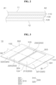
- FIG. 1 illustrates a pouch unit according to an embodiment of the present disclosure.
- FIG. 2 illustrates a cross section of a pouch unit of FIG. 1 taken along A1-A2.
- a pouch unit 10 may include a pouch sheet 100.
- the pouch sheet 100 may form a sheet shape.
- the pouch sheet 100 may form one surface and other surface.
- the pouch unit 10 may include a first pouch surface 11 and a second pouch surface 12.
- the first pouch surface 11 may be the one surface of the pouch sheet 10.
- the second pouch surface 12 may be the other surface of the pouch sheet 100.
- the pouch sheet 100 may form a side or an edge.
- the pouch sheet 100 may form four sides.
- the pouch sheet 100 may form a first pouch side 101, a second pouch side 102, a third pouch side 103, and a fourth pouch side 104.
- the pouch sides 101, 102, 103 and 104 may indicate at least one of the first pouch side 101, the second pouch side 102, the third pouch side 103, and the fourth pouch side 104.
- the first pouch side 101 and the second pouch side 102 may be positioned opposite each other.
- the third pouch side 103 and the fourth pouch side 104 may be positioned opposite each other.
- the first pouch side 101 may be connected to one end of the third pouch side 103 and one end of the fourth pouch side 104.
- the second pouch side 102 may be connected to other end of the third pouch side 103 and other end of the fourth pouch side 104.
- the pouch sheet 100 may form an area.
- the pouch unit 10 may include a central portion 200.
- the central portion 200 may form a part of the area of the pouch sheet 100.
- the central portion 200 may be spaced apart from the pouch sides 101, 102, 103 and 104.
- the pouch unit 10 may include a perimeter portion 300.
- the perimeter portion 300 may form another part of the area of the pouch sheet 100.
- the perimeter portion 300 may extend from the central portion 200 and lead to the pouch sides 101, 102, 103 and 104.
- the perimeter portion 300 may refer to an area between the central portion 200 and the pouch sides 101, 102, 103 and 104.
- the perimeter portion 300 may include an outer perimeter portion 310 and an inner perimeter portion 320.
- the outer perimeter portion 310 may refer to an area connected to the pouch sides 101, 102, 103 and 104 in the perimeter portion 300.
- the outer perimeter portion 310 may include a first outer perimeter portion 301 connected to the first pouch side 101.
- the outer perimeter portion 310 may include a second outer perimeter portion 302 connected to the second pouch side 102.
- the outer perimeter portion 310 may include a third outer perimeter portion 303 connected to the third pouch side 103.
- the outer perimeter portion 310 may include a fourth outer perimeter portion 304 connected to the fourth pouch side 104.
- the inner perimeter portion 320 may refer to an area spaced apart from the pouch sides 101, 102, 103 and 104 in the perimeter portion 300.
- the inner perimeter portion 320 may refer to an area excluding the outer perimeter portion 310 from the perimeter portion 300.
- the inner perimeter portion 320 may include a first inner perimeter portion 321.
- the first inner perimeter portion 321 may be positioned between the first outer perimeter portion 301 and the central portion 200.
- the first inner perimeter portion 321 may be positioned between the third outer perimeter portion 303 and the fourth outer perimeter portion 304.
- the inner perimeter portion 320 may include a second inner perimeter portion 322.
- the second inner perimeter portion 322 may be positioned between the second outer perimeter portion 302 and the central portion 200.
- the second inner perimeter portion 322 may be positioned between the third outer perimeter portion 303 and the fourth outer perimeter portion 304.
- the first perimeter portions 301 and 321 may indicate at least one of the first inner perimeter portion 321 and the first outer perimeter portion 301.
- the second perimeter portions 302 and 322 may indicate at least one of the second inner perimeter portion 322 and the second outer perimeter portion 302.
- the pouch sheet 100 may form a stacked layer structure.
- the pouch sheet 100 may include a first pouch layer 110.
- One surface of the first pouch layer 110 may form the first pouch surface 11.
- the first pouch layer 110 may be formed of a material containing synthetic resin.
- the pouch sheet 100 may include a second pouch layer 120.
- One surface of the second pouch layer 120 may face the first pouch layer 110.
- Other surface of the second pouch layer 120 may form the second pouch surface 12.
- the second pouch layer 120 may be formed of a material containing synthetic resin.
- the pouch sheet 100 may include a third pouch layer 130.
- the third pouch layer 130 may be disposed between the first pouch layer 110 and the second pouch layer 120.
- One surface of the third pouch layer 130 may be coupled to the other surface of the first pouch layer 110.
- Other surface of the third pouch layer 130 may be coupled to the one surface of the second pouch layer 120.
- the third pouch layer 130 may be formed of a material containing metal.
- the third pouch layer 130 may be formed of a material containing aluminum.
- FIG. 3 illustrates that an accommodation portion is formed on a pouch sheet.
- FIG. 4 illustrates a cross section of a pouch unit of FIG. 3 taken along B1-B2.
- the pouch unit 10 may include accommodation portions 210 and 220.
- the accommodation portions 210 and 220 may be formed in the central portion 200 (see FIG. 1 ).
- the accommodation portions 210 and 220 may accommodate at least a part of an electrode assembly.
- the accommodation portions 210 and 220 may include a first accommodation portion 210 and a second accommodation portion 220.
- the accommodation portions 210 and 220 may indicate at least one of the first accommodation portion 210 and the second accommodation portion 220.
- the first accommodation portion 210 may be spaced apart from the second accommodation portion 220.
- a connection portion 230 may connect the first accommodation portion 210 and the second accommodation portion 220.
- the first accommodation portion 210 and the second accommodation portion 220 may be disposed in parallel.
- the first pouch side 101, the first accommodation portion 210, the second accommodation portion 220, and the second pouch side 102 may be sequentially disposed.
- the first accommodation portion 210 may be disposed between the second accommodation portion 220 and the first pouch side 101.
- the second accommodation portion 220 may be disposed between the first accommodation portion 210 and the second pouch side 102.
- connection portion 230 may form a concave shape or a convex shape.
- connection portion 230 in the first pouch surface 11 may form a convex shape.
- connection portion 230 in the second pouch surface 12 may form a concave shape.
- the accommodation portions 210 and 220 may form a concave shape or a convex shape.
- the accommodation portions 210 and 220 in the first pouch surface 11 may form a concave shape.
- the accommodation portions 210 and 220 in the first pouch surface 11 may form an open space in a direction in which the first pouch surface 11 faces.
- the accommodation portions 210 and 220 in the second pouch surface 12 may form a convex shape.
- the first accommodation portion 210 may form a first accommodation space opened in the direction in which the first pouch surface 11 faces.
- the first accommodation space of the first accommodation portion 210 may accommodate a part of the electrode assembly.
- the second accommodation portion 220 may form a second accommodation space opened in the direction in which the first pouch surface 11 faces.
- the second accommodation space of the second accommodation portion 220 may accommodate another part of the electrode assembly.
- the accommodation space may indicate at least one of the first accommodation space and the second accommodation space.
- FIG. 5 illustrates that a perimeter portion bends due to formation of an accommodation portion.
- the pouch sheet 100 may be stretched.
- the pouch sheet 100 may be stretched at a boundary between the accommodation portions 210 and 220 and the perimeter portion 300. Due to this, a force directed toward the accommodation portions 210 and 220 may be formed in the perimeter portion 300.
- the accommodation portions 210 and 220 may be concave in the first pouch surface 11 and convex in the second pouch surface 12. Due to this, a stretched length of the first pouch surface 11 and a stretched length of the second pouch surface 12 may be different from each other at the boundary between the accommodation portions 210 and 220 and the perimeter portion 300. For example, at the boundary between the accommodation portions 210 and 220 and the perimeter portion 300, the stretched length of the second pouch surface 12 may be greater than the stretched length of the first pouch surface 11.
- a magnitude of a force that is formed in the second pouch surface 12 of the perimeter portion 300 and is directed toward the accommodation portions 210 and 220 may be greater than a magnitude of a force that is formed in the first pouch surface 11 of the perimeter portion 300 and is directed toward the accommodation portions 210 and 220.
- the perimeter portion 300 may be bent in a direction in which the second pouch surface 12 faces.
- the perimeter portion 300 of the pouch unit 10 may overlap and be coupled to each other after at least a part of the electrode assembly is accommodated in the accommodation portions 210 and 220.
- the first pouch surface 11 may face and contact at least a part of the electrode assembly.
- the second pouch surface 11 may form an outer surface of the battery cell.
- heat may be applied to the perimeter portion 300.
- a pressure may be applied to the perimeter portion 300 while applying heat to the perimeter portion 300.
- the bent perimeter portion 300 may be bent again after being flattened.
- FIG. 6 illustrates an area 'C' of FIG. 4 and illustrates that a notch is formed at a perimeter portion.
- FIG. 7 illustrates an area 'D' of FIG. 4 and illustrates that a notch is formed at a perimeter portion.
- the pouch unit 10 may include a notch portion 400.
- the notch portion 400 may be formed or positioned at the perimeter portion 300 (see FIG. 3 ).
- the notch portion 400 may be formed or positioned in one surface of the perimeter portion 300 (see FIG. 3 ).
- the notch portion 400 may be formed or positioned in the first pouch surface 11 of the perimeter portion 300 (see FIG. 3 ).
- the notch portion 400 may be concave on the first pouch surface 11 of the perimeter portion 300 (see FIG. 3 ).
- a thickness of the pouch sheet 100 (see FIG. 1 ) at the notch portion 400 may be less than a thickness of the pouch sheet 100 (see FIG. 1 ) in another area.
- the notch portion 400 may be adjacent to the boundary between the accommodation portions 210 and 220 and the perimeter portion 300 (see FIG. 3 ).
- the notch portion 400 may be formed by a die.
- the notch portion 400 may be formed by applying pressure to a part of the perimeter portion 300 (see FIG. 3 ).
- a bending phenomenon of the perimeter portion 300 can be compensated.
- a force directed toward the notch portion 400 may be formed on the first pouch surface 11 of the perimeter portion 300 (see FIG. 3 ) or the first pouch layer 110 (see FIG. 2 ).
- the force directed toward the notch portion 400 in the first pouch surface 11 of the perimeter portion 300 (see FIG. 3 ) or the first pouch layer 110 (see FIG. 2 ) may correspond to a force applied to the second pouch surface 12 of the perimeter portion 300 (see FIG. 3 ) or the second pouch layer 120 (see FIG. 2 ) due to the formation of the accommodation portions 210 and 220.
- the bending phenomenon of the perimeter portion 300 (see FIG. 3 ) illustrated in FIG. 5 can be alleviated by forming the notch portion 400 in the first pouch surface 11 of the perimeter portion 300 (see FIG. 3 ).
- a plurality of notch portions 400 may be provided.
- the notch portion 400 may include a first notch portion 401 and a second notch portion 402.
- the first notch portion 401 may be positioned between the first accommodation portion 210 and the first pouch side 101 (see FIG. 4 ).
- the first notch portion 401 may be adjacent to the first accommodation portion 210.
- the second notch portion 402 may be positioned between the second accommodation portion 220 and the second pouch side 102 (see FIG. 4 ).
- the second notch portion 402 may be adjacent to the second accommodation portion 220.
- the notch portion 400 may be formed at the perimeter portion 300.
- the notch portion 400 may be formed on the first pouch surface 11 of the perimeter portion 300.
- the notch portion 400 may be positioned in the perimeter portion 300 and may be formed alongside one side of the accommodation portions 210 and 220.
- the notch portion 400 may be formed alongside long edges of the accommodation portions 210 and 220.
- a long side of the first accommodation portion 210 and a long side of the second accommodation portion 220 may be positioned opposite each other in the pouch sheet 100.
- first notch portion 401 may be formed between the long side of the first accommodation portion 210 and the first pouch side 101 alongside the long side of the first accommodation portion 210.
- second notch portion 402 may be formed between the long side of the second accommodation portion 220 and the second pouch side 102 alongside the long side of the second accommodation portion 220.
- the notch portion 400 may be formed alongside short edges of the accommodation portions 210 and 220.
- a ratio of the long side to the short side of the accommodation portions 210 and 220 may be referred to as an aspect ratio.
- the aspect ratio may be 1 or more.
- the possibility of the bending phenomenon appearing in the perimeter portion 300 adjacent to the short sides of the accommodation portions 210 and 220 may decrease.
- the possibility of the bending phenomenon appearing in the perimeter portion 300 adj acent to the short sides of the accommodation portions 210 and 220 may increase.
- the notch portion 400 formed alongside the short sides of the accommodation portions 210 and 220 can effectively suppress the bending phenomenon appearing in the perimeter portion 300 adjacent to the short sides of the accommodation portions 210 and 220.
- the notch portion 400 may be formed alongside the upper side of the accommodation portions 210 and 220 and positioned between the third pouch side 103 and the accommodation portions 210 and 220.
- the notch portion 400 may be formed alongside the lower side of the accommodation portions 210 and 220 and positioned between the fourth pouch side 103 and the accommodation portions 210 and 220.
- the notch portion 400 may be formed at the perimeter portion 300 after heat is applied to the perimeter portion 300.
- heat may be applied to the perimeter portion 300 while the notch portion 400 is formed at the perimeter portion 300.
- heat may be applied to the perimeter portion 300.
- the notch portion 400 may be formed at the perimeter portion 300 after heat and pressure are applied to the perimeter portion 300.
- heat and pressure may be applied to the perimeter portion 300 while the notch portion 400 is formed at the perimeter portion 300.
- heat and pressure may be applied to the perimeter portion 300.
- FIG. 8 illustrates that a gas chamber is formed in a pouch unit of FIG. 3 .
- FIG. 9 illustrates a cross section of a pouch unit of FIG. 8 taken along E1-E2.
- the pouch unit 10 may include a gas chamber portion 320g.
- the gas chamber portion 320g may be formed at the inner perimeter portion 320 (see FIG. 3 ).
- the gas chamber portion 320g may form a concave shape or a convex shape.
- the gas chamber portion 320g in the first pouch surface 11 may form a concave shape.
- the gas chamber portion 320g in the first pouch surface 11 may form an open space (or a hollow portion) in the direction in which the first pouch surface 11 faces.
- the gas chamber portion 320g in the second pouch surface 12 may form a convex shape.
- the gas chamber portion 320g may include a first gas chamber portion 321g and a second gas chamber portion 322g.
- the first gas chamber portion 321g, the first accommodation portion 210, the second accommodation portion 220, and the second gas chamber portion 322g may be disposed sequentially.
- the gas chamber portion 320g may indicate at least one of the first gas chamber portion 321g and the second gas chamber portion 322g.
- the first gas chamber portion 321g may be formed at the first inner perimeter portion 321 (see FIG. 3 ).
- the first gas chamber portion 321g may be adjacent to the first accommodation portion 210.
- the first gas chamber portion 321g may be formed or positioned between the first accommodation portion 210 and the first pouch side 101.
- the first gas chamber portion 321g may form a first hollow portion opened in the direction in which the first pouch surface 11 faces.
- the second gas chamber portion 322g may be formed at the second inner perimeter portion 322 (see FIG. 3 ).
- the second gas chamber portion 322g may be adjacent to the second accommodation portion 220.
- the second gas chamber portion 322g may be formed or positioned between the second accommodation portion 220 and the second pouch side 102.
- the second gas chamber portion 322g may form a second hollow portion opened in the direction in which the first pouch surface 11 faces.
- the gas chamber portion 320g may be concave in the first pouch surface 11 and convex in the second pouch surface 12. Due to this, a stretched length of the first pouch surface 11 and a stretched length of the second pouch surface 12 may be different from each other at a boundary between the gas chamber portion 320g and the outer perimeter portion 310.
- the stretched length of the first pouch surface 11 or the first pouch layer 110 may be greater than the stretched length of the second pouch surface 12 or the second pouch layer 120 (see FIG. 2 ).
- a magnitude of a force that is formed in the second pouch surface 12 of the outer perimeter portion 310 and is directed toward the gas chamber portion 320g may be greater than a magnitude of a force that is formed in the first pouch surface 11 of the outer perimeter portion 310 and is directed toward the gas chamber portion 320g.
- a magnitude of a force that is formed in the second pouch surface 12 of the first outer perimeter portion 301 and is directed toward the first gas chamber portion 321g may be greater than a magnitude of a force that is formed in the first pouch surface 11 of the first outer perimeter portion 301 and is directed toward the first gas chamber portion 321g.
- a magnitude of a force that is formed in the second pouch surface 12 of the second outer perimeter portion 302 and is directed toward the second gas chamber portion 322g may be greater than a magnitude of a force that is formed in the first pouch surface 11 of the second outer perimeter portion 302 and is directed toward the second gas chamber portion 322g.
- first outer perimeter portion 301 may be bent in the direction in which the second pouch surface 12 faces
- second outer perimeter portion 302 may be bent in the direction in which the second pouch surface 12 faces
- FIG. 10 illustrates an area 'F' of FIG. 8 and illustrates that a notch is formed at an outer perimeter portion.
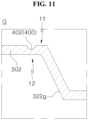
- FIG. 11 illustrates an area 'G' of FIG. 8 and illustrates that a notch is formed at an outer perimeter portion.
- the pouch unit 10 may include the notch portion 400.
- the notch portion 400 may be formed or positioned in the outer perimeter portion 310 (see FIG. 8 ).
- the notch portion 400 may be formed or positioned in the first pouch surface 11 of the outer perimeter portion 310 (see FIG. 8 ).
- the notch portion 400 may include the first notch portion 401 and the second notch portion 402.
- the notch portion 400 may be concave on the first pouch surface 11 of the outer perimeter portion 310 (see FIG. 8 ).
- a thickness of the pouch sheet 100 (see FIG. 1 ) at the notch portion 400 may be less than a thickness of the pouch sheet 100 (see FIG. 1 ) in another area.
- the notch portion 400 may be adjacent to a boundary between the gas chamber portion 320g and the outer perimeter portion 310.
- the shape and manufacturing process of the notch portion 400 illustrated in FIGS. 10 and 11 may be substantially the same as the shape and manufacturing process of the notch portion 400 illustrated in FIGS. 6 and 7 .
- the notch portion 400 illustrated in FIGS. 10 and 11 may be distinguished from the notch portion 400 illustrated in FIGS. 6 and 7 .
- the notch portion 400 illustrated in FIGS. 10 and 11 may be referred to as an "outer notch portion", and the notch portion 400 illustrated in FIGS. 6 and 7 may be referred to as an “inner notch portion”.
- the inner notch portion 400 (see FIGS. 6 and 7 ) may be formed or disposed between the accommodation portions 210 and 220 and the gas chamber portion 320g.
- the first notch portion 401 may be formed or positioned in the first outer perimeter portion 301.
- the first notch portion 401 may be disposed between the first gas chamber portion 321g (see FIG. 8 ) and the first pouch side 101 (see FIG. 8 ).
- the first notch portion 401 may be adjacent to a boundary between the first gas chamber portion 321g (see FIG. 8 ) and the first outer perimeter portion 301.
- the second notch portion 402 may be formed or positioned in the second outer perimeter portion 302.
- the second notch portion 402 may be disposed between the second gas chamber portion 322g (see FIG. 8 ) and the second pouch side 102 (see FIG. 8 ).
- the second notch portion 402 may be adjacent to a boundary between the second gas chamber portion 322g (see FIG. 8 ) and the second outer perimeter portion 302.
- the notch portion 400 may form an extended shape in one direction.
- the notch portion 400 may form an elongated shape in one direction.
- the notch portion 400 may form an extended shape or an elongated shape in a longitudinal direction of the pouch unit 10.
- the longitudinal direction of the pouch unit 10 may be a direction across a width direction of the pouch unit 10.
- the width direction of the pouch unit 10 may be a direction in which the first accommodation portion 210 and the second accommodation portion 220 are disposed in parallel.
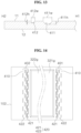
- FIG. 12 illustrates a pouch unit provided with a notch segment.
- the first pouch surface 11 (see FIG. 9 ) of the pouch unit 10 may be observed.
- FIG. 13 illustrates a cross section of a pouch unit of FIG. 12 taken along H1-H2.
- the notch portion 400 may include a notch segment 410.
- a plurality of notch segments 410 may be provided.
- the plurality of notch segments 410 may include a first notch segment 411 and a second notch segment 412.
- the notch portion 400 may include the first notch portion 401 and the second notch portion 402.
- the first notch portion 401 may be positioned between the first gas chamber portion 321g and the first pouch side 101.
- the second notch portion 402 may be positioned between the second gas chamber portion 322g and the second pouch side 102.
- Each of the first notch portion 401 and the second notch portion 402 may include a plurality of notch segments 410.
- each of the first notch portion 401 and the second notch portion 402 may include a first notch segment 411 and a second notch segment 412.
- the notch segment 410 may form an extended shape or an elongated shape in the longitudinal direction of the pouch unit 10.
- the first notch segment 411 may be disposed between the gas chamber portion 320g and the second notch segment 412.
- the notch segment 410 may be recessed in the first pouch surface 11 of the outer perimeter portion 310.
- a first notch depth 411h may indicate a recessed depth of the first notch segment 411 in the first pouch surface 11.
- a second notch depth 412h may indicate a recessed depth of the second notch segment 412 in the first pouch surface 11. The first notch depth 411h may be greater than the second notch depth 412h.
- a first notch width 411w may indicate a width of the first notch segment 411 defined in the first pouch surface 11.
- a second notch width 412w may indicate a width of the second notch segment 412 defined in the first pouch surface 11.
- the first notch width 411w may be greater than the second notch width 412w.
- the first notch segment 411 and the second notch segment 412 are formed at the outer perimeter portion 310, and thus the bending phenomenon of the outer perimeter portion 310 can be alleviated more effectively.
- FIG. 14 illustrates a pouch unit having a notch pattern in accordance with an embodiment of the present disclosure.
- the first pouch surface 11 (see FIG. 9 ) of the pouch unit 10 may be observed.
- the notch portion 400 may include the first notch portion 401 and the second notch portion 402.
- the first notch portion 401 may be positioned between the first gas chamber portion 321g and the first pouch side 101.
- the second notch portion 402 may be positioned between the second gas chamber portion 322g and the second pouch side 102.
- the notch portion 400 may include a plurality of notch segments 410.
- the plurality of notch segments 410 may form a notch pattern 420.
- Each of the first notch portion 401 and the second notch portion 402 may include the notch pattern 420.
- the notch pattern 420 may include a first notch pattern 421 and a second notch pattern 422.
- the first notch pattern 421 may be positioned between the gas chamber portion 320g and the second notch pattern 422.
- Each of the first notch pattern 421 and the second notch pattern 422 may include a plurality of notch segments 410.
- a number density of the first notch pattern 421 may be different from a number density of the second notch pattern 422.
- the number density of the first notch pattern 421 may be greater than the number density of the second notch pattern 422.
- the number density of the first notch pattern 421 may be a number density of the plurality of notch segments 410 included in the first notch pattern 421.
- the number density of the second notch pattern 422 may be a number density of the plurality of notch segments 410 included in the second notch pattern 422.
- the number density may be the number of notch segments 410 per unit area of the pouch sheet 100 (see FIG. 1 ).
- the number density of the plurality of notch segments 410 positioned in the first outer perimeter portion 301 may decrease as it goes from the first gas chamber portion 321g to the first pouch side 101.
- the number density of the plurality of notch segments 410 positioned in the second outer perimeter portion 302 may decrease as it goes from the second gas chamber portion 322g to the second pouch side 102.
- the notch pattern 420 with a number density profile illustrated in FIG. 14 is formed on the outer perimeter portion 310, and thus the bending phenomenon of the outer perimeter portion 310 can be alleviated more effectively.
- FIG. 15 illustrates a battery cell according to an embodiment of the present disclosure.
- FIG. 16 illustrates a cross section of a battery cell of FIG. 15 taken along I1-I2.
- the battery cell 1 may include the pouch unit 10.
- the pouch unit 10 may form a sealed pouch bag.
- the battery cell 1 may include an electrode assembly 20.
- the sealed pouch bag of the pouch unit 10 may accommodate the electrode assembly 20.
- the electrode assembly 20 may extend from one end and lead to other end.
- the electrode assembly 20 may extend from one end in the longitudinal direction and lead to other end.
- the longitudinal direction of the electrode assembly 20 may be the longitudinal direction of the pouch unit 10.
- the battery cell 1 may include an electrode lead 30.
- a plurality of electrode leads 30 may be provided.
- the plurality of electrode leads 30 may include a first electrode lead 31 and a second electrode lead 32.
- the first electrode lead 31 may be connected to the one end of the electrode assembly 20.
- the second electrode lead 32 may be connected to the other end of the electrode assembly 20.
- the first accommodation portion 210 may face one surface of the electrode assembly 20.
- the first accommodation portion 210 may accommodate a part of the electrode assembly 20.
- the second accommodation portion 220 may face another surface of the electrode assembly 20.
- the second accommodation portion 220 may accommodate another part of the electrode assembly 20.
- FIG. 17 illustrates an area ⁇ J' of FIG. 16 .
- the pouch unit 10 accommodating the electrode assembly 20 may be folded and sealed.
- the first accommodation portion 210 and the second accommodation portion 220 may be disposed to face each other.
- the first gas chamber portion 321g and the second gas chamber portion 322g may be disposed to face each other.
- the first outer perimeter portion 301 and the second outer perimeter portion 302 may be attached and coupled to each other while facing each other.
- the first outer perimeter portion 301 and the second outer perimeter portion 302 may receive a bending force in a direction away from each other. Since the notch portion 400 is formed at the first outer perimeter portion 301 and the second outer perimeter portion 302, the first outer perimeter portion 301 and the second outer perimeter portion 302 can be effectively coupled to each other.
- the first notch portion 401 may be formed at the first outer perimeter portion 301.
- the second notch portion 402 may be formed at the second outer perimeter portion 302.
- the first notch portion 401 and the second notch portion 402 may face each other.
- the first notch portion 401 may be concave with reference to the second outer perimeter portion 302.
- the second notch portion 402 may be concave with reference to the first outer perimeter portion 301.
- FIG. 18 is a flow chart illustrating a method of manufacturing a pouch unit according to an embodiment of the present disclosure.
- a method S10 of manufacturing the pouch unit may include a step S100 of bending the pouch sheet 100.
- the pouch sheet 100 may be molded by being pressed by a die.
- the accommodation portions 210 and 220 and/or the gas chamber portion 320g may be formed.
- the method S10 of manufacturing the pouch unit may include a step S200 of notching the pouch sheet 100.
- pressure may be applied to the pouch sheet 100 to form the notch portion 400.
- FIG. 19 is a flow chart illustrating a pouch sheet bending step.
- the pouch sheet bending step S100 may include a step S110 of forming the accommodation portion.
- the accommodation portions 210 and 220 may be formed on the pouch sheet 100.
- the accommodation portion forming step S110 may include a first accommodation portion forming step S111 and a second accommodation portion forming step S112.
- the first accommodation portion 210 may be formed on the pouch sheet 100.
- the second accommodation portion forming step S112 the second accommodation portion 220 may be formed on the pouch sheet 100.
- the first accommodation portion forming step S111 and the second accommodation portion forming step S112 may be performed at the same time.
- the pouch sheet bending step S100 may include a step S120 of forming the gas chamber portion.
- the gas chamber portion 320g may be formed on the pouch sheet 100.
- the gas chamber portion forming step S120 and the accommodation portion forming step S110 may be performed at the same time.
- the gas chamber portion forming step S120 may include a first gas chamber portion forming step S121 and a second gas chamber portion forming step S122.
- the first gas chamber portion 321g may be formed in the pouch sheet 100.
- the second gas chamber portion forming step S122 the second gas chamber portion 322g may be formed in the pouch sheet 100.
- the first gas chamber portion forming step S121 and the second gas chamber portion forming step S122 may be performed at the same time.
- FIG. 20 is a flow chart illustrating a pouch sheet notching step.
- the pouch sheet notching step S200 may include a first notch portion forming step S210 and a second notch portion forming step S220.
- the first notch portion forming step S210 the first notch portion 401 may be formed on the pouch sheet 100.
- the second notch portion forming step S220 the second notch portion 402 may be formed on the pouch sheet 100.
- the first notch portion forming step S210 and the second notch portion forming step S220 may be performed at the same time.
- Each of the first notch portion forming step S210 and the second notch portion forming step S220 may include a step of applying at least one of heat and pressure to the perimeter portion 300. That is, in a process of forming the notch portion 400, heat or/and pressure may be applied to the perimeter portion 300.
- the notch portion 400 may be positioned between the accommodation portions 210 and 220 and the gas chamber portions 321g and 322g.
- the first notch portion 401 may be positioned between the first accommodation portion 210 and the first gas chamber portion 321g on the pouch sheet 100.
- the second notch portion 402 may be positioned between the second accommodation portion 220 and the second gas chamber portion 322g on the pouch sheet 100.
- a phenomenon in which the gas chamber portions 321g and 322g are bent with respect to the accommodation portions 210 and 220 can be suppressed.
- the first notch portion 401 is formed between the first accommodation portion 210 and the first gas chamber portion 321g on the pouch sheet 100
- a phenomenon in which the first gas chamber portion 321g are bent with respect to the first accommodation portion 210 can be suppressed.
- the second notch portion 402 is formed between the second accommodation portion 220 and the second gas chamber portion 322g on the pouch sheet 100, a phenomenon in which the second gas chamber portion 322g are bent with respect to the second accommodation portion 210 can be suppressed.
Landscapes
- Chemical & Material Sciences (AREA)
- Chemical Kinetics & Catalysis (AREA)
- Electrochemistry (AREA)
- General Chemical & Material Sciences (AREA)
- Engineering & Computer Science (AREA)
- Mechanical Engineering (AREA)
- Manufacturing & Machinery (AREA)
- Bag Frames (AREA)
- Sealing Battery Cases Or Jackets (AREA)
Abstract
A pouch unit and a battery cell including the same are disclosed. The pouch unit comprises a pouch sheet (100) having an inner surface and an outer surface opposite the inner surface, an accommodation portion formed on the pouch sheet (100), the accommodation portion forming an accommodation space that is open in a direction in which the inner surface faces, a perimeter portion (300) formed on the pouch sheet (100), the perimeter portion (300) (300)being positioned between a perimeter of the pouch sheet (100) and the accommodation portion, and a notch portion formed alongside a side of the accommodation portion at the perimeter portion (300), the notch portion being concave on the inner surface.
Description
- The present disclosure relates to a pouch unit and a battery cell including the same.
- In a secondary battery using a pouch sheet as an exterior material, the pouch sheet accommodates and seals an electrode assembly. The pouch sheet may form a structure in which a plurality of layers are stacked. The pouch sheet may be molded to have an accommodation space by a die so that the electrode assembly is accommodated in the pouch sheet.
- In order to increase an energy density of a battery cell, the accommodation space formed in the pouch sheet may deepens. As the accommodation space deepens, a difference in the degree of stretching between the layers constituting the pouch sheet may increase, which may lead to bending of the pouch sheet. If the pouch sheet is bent, a problem may occur in a process of attaching and sealing the pouch sheet.
(Patent Document 1)KR 10-2014-0091222 A - An object of the present disclosure is to address the above-described and other problems.
- Another object of the present disclosure is to provide a pouch unit suppressing bending of a pouch sheet and a battery cell including the pouch unit.
- Another object of the present disclosure is to provide a pouch unit including a notch portion concave on an inner surface of a pouch sheet and a battery cell including the pouch unit.
- Another object of the present disclosure is to provide a pouch unit including a notch portion adjacent to an accommodation portion accommodating an electrode assembly and a battery cell including the pouch unit.
- Another object of the present disclosure is to provide a pouch unit including a notch portion adjacent to a gas chamber portion and a battery cell including the pouch unit.
- In order to achieve the above-described and other objects and needs, in one aspect of the present disclosure, there is provided a pouch unit comprising a pouch sheet having an inner surface and an outer surface opposite the inner surface; an accommodation portion formed on the pouch sheet, the accommodation portion forming an accommodation space that is open in a direction in which the inner surface faces; a perimeter portion formed on the pouch sheet, the perimeter portion being positioned between a perimeter of the pouch sheet and the accommodation portion; and a notch portion formed alongside a side of the accommodation portion at the perimeter portion, the notch portion being concave on the inner surface.
- In another aspect of the present disclosure, there is provided a battery cell comprising an electrode assembly; and a pouch unit accommodating the electrode assembly, the pouch unit being sealed, wherein the pouch unit includes a pouch sheet having an inner surface contacting the electrode assembly and an outer surface opposite the inner surface; an accommodation portion formed on the pouch sheet and accommodating the electrode assembly, the accommodation portion including a first accommodation portion facing a surface of the electrode assembly and a second accommodation portion facing another surface of the electrode assembly; a first perimeter portion formed on the pouch sheet, the first perimeter portion extending from the first accommodation portion and leading to a first pouch side of the perimeter of the pouch sheet; a second perimeter portion formed on the pouch sheet, the second perimeter portion extending from the second accommodation portion and leading to a second pouch side of the perimeter of the pouch sheet, the second perimeter portion facing and contacting the first perimeter portion; a first notch portion extending alongside a side of the first accommodation portion at the first perimeter portion, the first notch portion being concave on the inner surface of the pouch sheet; and a second notch portion extending alongside a side of the second accommodation portion at the second perimeter portion, the second notch portion being concave on the inner surface of the pouch sheet.
- In another aspect of the present disclosure, there is provided a method of manufacturing a pouch unit comprising bending a pouch sheet having an inner surface and an outer surface opposite the inner surface to form an accommodation portion configured to form an accommodation space that is open in a direction in which the inner surface faces; and forming a notch portion concave on the inner surface alongside a side of the accommodation portion at a perimeter portion, the perimeter portion being formed on the pouch sheet and being positioned between a perimeter of the pouch sheet and the accommodation portion.
- Effects of a pouch unit and a battery cell including the same according to the present disclosure are described as follows.
- According to at least one aspect of the present disclosure, the present disclosure can provide a pouch unit suppressing bending of a pouch sheet and a battery cell including the pouch unit.
- According to at least one aspect of the present disclosure, the present disclosure can provide a pouch unit including a notch portion concave on an inner surface of a pouch sheet and a battery cell including the pouch unit.
- According to at least one aspect of the present disclosure, the present disclosure can provide a pouch unit including a notch portion adjacent to an accommodation portion accommodating an electrode assembly and a battery cell including the pouch unit.
- According to at least one aspect of the present disclosure, the present disclosure can provide a pouch unit including a notch portion adjacent to a gas chamber portion and a battery cell including the pouch unit.
- Additional scope of applicability of the present disclosure will become apparent from the detailed description given blow. However, it should be understood that the detailed description and specific examples such as embodiments of the present disclosure are given merely by way of example, since various changes and modifications within the spirit and scope of the present disclosure will become apparent to those skilled in the art from the detailed description.
- The accompanying drawings, which are included to provide a further understanding of the disclosure and are incorporated in and constitute a part of the disclosure, illustrate embodiments of the disclosure and together with the description serve to explain the principle of the disclosure.
-
FIG. 1 illustrates a pouch unit according to an embodiment of the present disclosure. -
FIG. 2 illustrates a cross section of a pouch unit ofFIG. 1 taken along A1-A2. -
FIG. 3 illustrates that an accommodation portion is formed on a pouch sheet. -
FIG. 4 illustrates a cross section of a pouch unit ofFIG. 3 taken along B1-B2. -
FIG. 5 illustrates that a perimeter portion bends due to formation of an accommodation portion. -
FIG. 6 illustrates an area 'C' ofFIG. 4 and illustrates that a notch is formed at a perimeter portion. -
FIG. 7 illustrates an area 'D' ofFIG. 4 and illustrates that a notch is formed at a perimeter portion. -
FIG. 8 illustrates that a gas chamber is formed in a pouch unit ofFIG. 3 . -
FIG. 9 illustrates a cross section of a pouch unit ofFIG. 8 taken along E1-E2. -
FIG. 10 illustrates an area 'F' ofFIG. 8 and illustrates that a notch is formed at an outer perimeter portion. -
FIG. 11 illustrates an area 'G' ofFIG. 8 and illustrates that a notch is formed at an outer perimeter portion. -
FIG. 12 illustrates a pouch unit provided with a notch segment. -
FIG. 13 illustrates a cross section of a pouch unit ofFIG. 12 taken along H1-H2. -
FIG. 14 illustrates a pouch unit having a notch pattern in accordance with an embodiment of the present disclosure. -
FIG. 15 illustrates a battery cell according to an embodiment of the present disclosure. -
FIG. 16 illustrates a cross section of a battery cell ofFIG. 15 taken along I1-I2. -
FIG. 17 illustrates an area `J' ofFIG. 16 . -
FIG. 18 is a flow chart illustrating a method of manufacturing a pouch unit according to an embodiment of the present disclosure. -
FIG. 19 is a flow chart illustrating a pouch sheet bending step. -
FIG. 20 is a flow chart illustrating a pouch sheet notching step. - Reference will now be made in detail to embodiments of the disclosure, examples of which are illustrated in the accompanying drawings. Wherever possible, the same reference numbers will be used throughout the drawings to refer to the same or like parts. In general, a suffix such as "module" and "unit" may be used to refer to elements or components. Use of such a suffix herein is merely intended to facilitate description of the present disclosure, and the suffix itself is not intended to give any special meaning or function. It will be noted that a detailed description of known arts will be omitted if it is determined that the detailed description of the known arts can obscure the embodiments of the disclosure. The accompanying drawings are used to help easily understand various technical features and it should be understood that embodiments presented herein are not limited by the accompanying drawings. As such, the present disclosure should be construed to extend to any alterations, equivalents and substitutes in addition to those which are particularly set out in the accompanying drawings.
- The terms including an ordinal number such as first, second, etc. may be used to describe various components, but the components are not limited by such terms. The terms are used only for the purpose of distinguishing one component from other components.
- When any component is described as "being connected" or "being coupled" to other component, this should be understood to mean that another component may exist between them, although any component may be directly connected or coupled to the other component. In contrast, when any component is described as "being directly connected" or "being directly coupled" to other component, this should be understood to mean that no component exists between them.
- A singular expression can include a plural expression as long as it does not have an apparently different meaning in context.
- In the present disclosure, terms "include" and "have" should be understood to be intended to designate that illustrated features, numbers, steps, operations, components, parts or combinations thereof are present and not to preclude the existence of one or more different features, numbers, steps, operations, components, parts or combinations thereof, or the possibility of the addition thereof.
- In the drawings, sizes of the components may be exaggerated or reduced for convenience of explanation. For example, the size and the thickness of each component illustrated in the drawings are arbitrarily illustrated for convenience of explanation, and thus the present disclosure is not limited thereto unless specified as such.
- If any embodiment is implementable differently, a specific order of processes may be performed differently from the order described. For example, two consecutively described processes may be performed substantially at the same time, or performed in the order opposite to the described order.
- In the following embodiments, when layers, areas, components, etc. are connected, the following embodiments include both the case where layers, areas, and components are directly connected, and the case where layers, areas, and components are indirectly connected to other layers, areas, and components intervening between them. For example, when layers, areas, components, etc. are electrically connected, the present disclosure includes both the case where layers, areas, and components are directly electrically connected, and the case where layers, areas, and components are indirectly electrically connected to other layers, areas, and components intervening between them.
-
FIG. 1 illustrates a pouch unit according to an embodiment of the present disclosure.FIG. 2 illustrates a cross section of a pouch unit ofFIG. 1 taken along A1-A2. - Referring to
FIGS. 1 and2 , apouch unit 10 according to an embodiment of the present disclosure may include apouch sheet 100. Thepouch sheet 100 may form a sheet shape. - For example, the
pouch sheet 100 may form one surface and other surface. For example, thepouch unit 10 may include afirst pouch surface 11 and asecond pouch surface 12. Thefirst pouch surface 11 may be the one surface of thepouch sheet 10. Thesecond pouch surface 12 may be the other surface of thepouch sheet 100. - The
pouch sheet 100 may form a side or an edge. For example, thepouch sheet 100 may form four sides. For example, thepouch sheet 100 may form afirst pouch side 101, asecond pouch side 102, athird pouch side 103, and afourth pouch side 104. The pouch sides 101, 102, 103 and 104 may indicate at least one of thefirst pouch side 101, thesecond pouch side 102, thethird pouch side 103, and thefourth pouch side 104. - The
first pouch side 101 and thesecond pouch side 102 may be positioned opposite each other. Thethird pouch side 103 and thefourth pouch side 104 may be positioned opposite each other. Thefirst pouch side 101 may be connected to one end of thethird pouch side 103 and one end of thefourth pouch side 104. Thesecond pouch side 102 may be connected to other end of thethird pouch side 103 and other end of thefourth pouch side 104. - The
pouch sheet 100 may form an area. For example, thepouch unit 10 may include acentral portion 200. Thecentral portion 200 may form a part of the area of thepouch sheet 100. Thecentral portion 200 may be spaced apart from the pouch sides 101, 102, 103 and 104. - The
pouch unit 10 may include aperimeter portion 300. Theperimeter portion 300 may form another part of the area of thepouch sheet 100. Theperimeter portion 300 may extend from thecentral portion 200 and lead to the pouch sides 101, 102, 103 and 104. Theperimeter portion 300 may refer to an area between thecentral portion 200 and the pouch sides 101, 102, 103 and 104. - The
perimeter portion 300 may include anouter perimeter portion 310 and aninner perimeter portion 320. Theouter perimeter portion 310 may refer to an area connected to the pouch sides 101, 102, 103 and 104 in theperimeter portion 300. - For example, the
outer perimeter portion 310 may include a firstouter perimeter portion 301 connected to thefirst pouch side 101. For example, theouter perimeter portion 310 may include a secondouter perimeter portion 302 connected to thesecond pouch side 102. For example, theouter perimeter portion 310 may include a thirdouter perimeter portion 303 connected to thethird pouch side 103. For example, theouter perimeter portion 310 may include a fourthouter perimeter portion 304 connected to thefourth pouch side 104. - The
inner perimeter portion 320 may refer to an area spaced apart from the pouch sides 101, 102, 103 and 104 in theperimeter portion 300. Theinner perimeter portion 320 may refer to an area excluding theouter perimeter portion 310 from theperimeter portion 300. - For example, the
inner perimeter portion 320 may include a firstinner perimeter portion 321. The firstinner perimeter portion 321 may be positioned between the firstouter perimeter portion 301 and thecentral portion 200. The firstinner perimeter portion 321 may be positioned between the thirdouter perimeter portion 303 and the fourthouter perimeter portion 304. - For example, the
inner perimeter portion 320 may include a secondinner perimeter portion 322. The secondinner perimeter portion 322 may be positioned between the secondouter perimeter portion 302 and thecentral portion 200. The secondinner perimeter portion 322 may be positioned between the thirdouter perimeter portion 303 and the fourthouter perimeter portion 304. - The
first perimeter portions inner perimeter portion 321 and the firstouter perimeter portion 301. Thesecond perimeter portions inner perimeter portion 322 and the secondouter perimeter portion 302. - The
pouch sheet 100 may form a stacked layer structure. For example, thepouch sheet 100 may include afirst pouch layer 110. One surface of thefirst pouch layer 110 may form thefirst pouch surface 11. Thefirst pouch layer 110 may be formed of a material containing synthetic resin. - For example, the
pouch sheet 100 may include asecond pouch layer 120. One surface of thesecond pouch layer 120 may face thefirst pouch layer 110. Other surface of thesecond pouch layer 120 may form thesecond pouch surface 12. Thesecond pouch layer 120 may be formed of a material containing synthetic resin. - For example, the
pouch sheet 100 may include athird pouch layer 130. Thethird pouch layer 130 may be disposed between thefirst pouch layer 110 and thesecond pouch layer 120. One surface of thethird pouch layer 130 may be coupled to the other surface of thefirst pouch layer 110. Other surface of thethird pouch layer 130 may be coupled to the one surface of thesecond pouch layer 120. Thethird pouch layer 130 may be formed of a material containing metal. For example, thethird pouch layer 130 may be formed of a material containing aluminum. -
FIG. 3 illustrates that an accommodation portion is formed on a pouch sheet.FIG. 4 illustrates a cross section of a pouch unit ofFIG. 3 taken along B1-B2. - Referring to
FIGS. 3 and4 , thepouch unit 10 may includeaccommodation portions FIG. 1 ) is molded, theaccommodation portions FIG. 1 ). Theaccommodation portions - The
accommodation portions first accommodation portion 210 and asecond accommodation portion 220. Theaccommodation portions first accommodation portion 210 and thesecond accommodation portion 220. Thefirst accommodation portion 210 may be spaced apart from thesecond accommodation portion 220. Aconnection portion 230 may connect thefirst accommodation portion 210 and thesecond accommodation portion 220. - The
first accommodation portion 210 and thesecond accommodation portion 220 may be disposed in parallel. For example, thefirst pouch side 101, thefirst accommodation portion 210, thesecond accommodation portion 220, and thesecond pouch side 102 may be sequentially disposed. - The
first accommodation portion 210 may be disposed between thesecond accommodation portion 220 and thefirst pouch side 101. Thesecond accommodation portion 220 may be disposed between thefirst accommodation portion 210 and thesecond pouch side 102. - The
connection portion 230 may form a concave shape or a convex shape. For example, theconnection portion 230 in thefirst pouch surface 11 may form a convex shape. For example, theconnection portion 230 in thesecond pouch surface 12 may form a concave shape. - The
accommodation portions accommodation portions first pouch surface 11 may form a concave shape. - For example, the
accommodation portions first pouch surface 11 may form an open space in a direction in which thefirst pouch surface 11 faces. For example, theaccommodation portions second pouch surface 12 may form a convex shape. - For example, the
first accommodation portion 210 may form a first accommodation space opened in the direction in which thefirst pouch surface 11 faces. The first accommodation space of thefirst accommodation portion 210 may accommodate a part of the electrode assembly. - For example, the
second accommodation portion 220 may form a second accommodation space opened in the direction in which thefirst pouch surface 11 faces. The second accommodation space of thesecond accommodation portion 220 may accommodate another part of the electrode assembly. The accommodation space may indicate at least one of the first accommodation space and the second accommodation space. -
FIG. 5 illustrates that a perimeter portion bends due to formation of an accommodation portion. - Referring to
FIGS. 3 to 5 , in a process of molding thepouch sheet 100 to form theaccommodation portions pouch sheet 100 may be stretched. For example, thepouch sheet 100 may be stretched at a boundary between theaccommodation portions perimeter portion 300. Due to this, a force directed toward theaccommodation portions perimeter portion 300. - The
accommodation portions first pouch surface 11 and convex in thesecond pouch surface 12. Due to this, a stretched length of thefirst pouch surface 11 and a stretched length of thesecond pouch surface 12 may be different from each other at the boundary between theaccommodation portions perimeter portion 300. For example, at the boundary between theaccommodation portions perimeter portion 300, the stretched length of thesecond pouch surface 12 may be greater than the stretched length of thefirst pouch surface 11. - Hence, a magnitude of a force that is formed in the
second pouch surface 12 of theperimeter portion 300 and is directed toward theaccommodation portions first pouch surface 11 of theperimeter portion 300 and is directed toward theaccommodation portions perimeter portion 300 may be bent in a direction in which thesecond pouch surface 12 faces. - The
perimeter portion 300 of the pouch unit 10 (seeFIG. 1 ) may overlap and be coupled to each other after at least a part of the electrode assembly is accommodated in theaccommodation portions first pouch surface 11 may face and contact at least a part of the electrode assembly. Thesecond pouch surface 11 may form an outer surface of the battery cell. - When the
perimeter portion 300 is bent in the direction in which thesecond pouch surface 12 faces, it may be difficult to attach theperimeter portion 300 facing each other. Therefore, it is necessary to flatten thebent perimeter portion 300. - In order to flatten the
bent perimeter portion 300, heat may be applied to theperimeter portion 300. Alternatively, a pressure may be applied to theperimeter portion 300 while applying heat to theperimeter portion 300. However, even if heat is applied to thebent perimeter portion 300 or even if both heat and pressure are applied to thebent perimeter portion 300, thebent perimeter portion 300 may be bent again after being flattened. -
FIG. 6 illustrates an area 'C' ofFIG. 4 and illustrates that a notch is formed at a perimeter portion.FIG. 7 illustrates an area 'D' ofFIG. 4 and illustrates that a notch is formed at a perimeter portion. - Referring to
FIGS. 6 and7 , the pouch unit 10 (seeFIG. 3 ) may include anotch portion 400. Thenotch portion 400 may be formed or positioned at the perimeter portion 300 (seeFIG. 3 ). For example, thenotch portion 400 may be formed or positioned in one surface of the perimeter portion 300 (seeFIG. 3 ). For example, thenotch portion 400 may be formed or positioned in thefirst pouch surface 11 of the perimeter portion 300 (seeFIG. 3 ). - For example, the
notch portion 400 may be concave on thefirst pouch surface 11 of the perimeter portion 300 (seeFIG. 3 ). A thickness of the pouch sheet 100 (seeFIG. 1 ) at thenotch portion 400 may be less than a thickness of the pouch sheet 100 (seeFIG. 1 ) in another area. For example, thenotch portion 400 may be adjacent to the boundary between theaccommodation portions FIG. 3 ). - The
notch portion 400 may be formed by a die. For example, thenotch portion 400 may be formed by applying pressure to a part of the perimeter portion 300 (seeFIG. 3 ). By forming or positioning thenotch portion 400 in thefirst pouch surface 11 to be adjacent to the boundary between theaccommodation portions FIG. 3 ), a bending phenomenon of the perimeter portion 300 (seeFIG. 3 ) can be compensated. - For example, when the
notch portion 400 is formed on thefirst pouch surface 11 of the perimeter portion 300 (seeFIG. 3 ), a force directed toward thenotch portion 400 may be formed on thefirst pouch surface 11 of the perimeter portion 300 (seeFIG. 3 ) or the first pouch layer 110 (seeFIG. 2 ). - The force directed toward the
notch portion 400 in thefirst pouch surface 11 of the perimeter portion 300 (seeFIG. 3 ) or the first pouch layer 110 (seeFIG. 2 ) may correspond to a force applied to thesecond pouch surface 12 of the perimeter portion 300 (seeFIG. 3 ) or the second pouch layer 120 (seeFIG. 2 ) due to the formation of theaccommodation portions - In other words, the bending phenomenon of the perimeter portion 300 (see
FIG. 3 ) illustrated inFIG. 5 can be alleviated by forming thenotch portion 400 in thefirst pouch surface 11 of the perimeter portion 300 (seeFIG. 3 ). - A plurality of
notch portions 400 may be provided. For example, thenotch portion 400 may include afirst notch portion 401 and asecond notch portion 402. Thefirst notch portion 401 may be positioned between thefirst accommodation portion 210 and the first pouch side 101 (seeFIG. 4 ). Thefirst notch portion 401 may be adjacent to thefirst accommodation portion 210. Thesecond notch portion 402 may be positioned between thesecond accommodation portion 220 and the second pouch side 102 (seeFIG. 4 ). Thesecond notch portion 402 may be adjacent to thesecond accommodation portion 220. - Referring to
FIGS. 1 to 7 , thenotch portion 400 may be formed at theperimeter portion 300. For example, thenotch portion 400 may be formed on thefirst pouch surface 11 of theperimeter portion 300. For example, thenotch portion 400 may be positioned in theperimeter portion 300 and may be formed alongside one side of theaccommodation portions - For example, the
notch portion 400 may be formed alongside long edges of theaccommodation portions first accommodation portion 210 and a long side of thesecond accommodation portion 220 may be positioned opposite each other in thepouch sheet 100. - For example, the
first notch portion 401 may be formed between the long side of thefirst accommodation portion 210 and thefirst pouch side 101 alongside the long side of thefirst accommodation portion 210. For example, thesecond notch portion 402 may be formed between the long side of thesecond accommodation portion 220 and thesecond pouch side 102 alongside the long side of thesecond accommodation portion 220. - For another example, the
notch portion 400 may be formed alongside short edges of theaccommodation portions accommodation portions - As the aspect ratio increases, the possibility of the bending phenomenon appearing in the
perimeter portion 300 adjacent to the short sides of theaccommodation portions perimeter portion 300 adj acent to the short sides of theaccommodation portions - When the aspect ratio is relatively small, the
notch portion 400 formed alongside the short sides of theaccommodation portions perimeter portion 300 adjacent to the short sides of theaccommodation portions - For example, the
notch portion 400 may be formed alongside the upper side of theaccommodation portions third pouch side 103 and theaccommodation portions notch portion 400 may be formed alongside the lower side of theaccommodation portions fourth pouch side 103 and theaccommodation portions - The
notch portion 400 may be formed at theperimeter portion 300 after heat is applied to theperimeter portion 300. For another example, heat may be applied to theperimeter portion 300 while thenotch portion 400 is formed at theperimeter portion 300. For another example, after thenotch portion 400 is formed at theperimeter portion 300, heat may be applied to theperimeter portion 300. - The
notch portion 400 may be formed at theperimeter portion 300 after heat and pressure are applied to theperimeter portion 300. For another example, heat and pressure may be applied to theperimeter portion 300 while thenotch portion 400 is formed at theperimeter portion 300. For another example, after thenotch portion 400 is formed at theperimeter portion 300, heat and pressure may be applied to theperimeter portion 300. -
FIG. 8 illustrates that a gas chamber is formed in a pouch unit ofFIG. 3 .FIG. 9 illustrates a cross section of a pouch unit ofFIG. 8 taken along E1-E2. - Referring to
FIGS. 8 and9 , thepouch unit 10 may include agas chamber portion 320g. Thegas chamber portion 320g may be formed at the inner perimeter portion 320 (seeFIG. 3 ). Thegas chamber portion 320g may form a concave shape or a convex shape. - For example, the
gas chamber portion 320g in thefirst pouch surface 11 may form a concave shape. For example, thegas chamber portion 320g in thefirst pouch surface 11 may form an open space (or a hollow portion) in the direction in which thefirst pouch surface 11 faces. For example, thegas chamber portion 320g in thesecond pouch surface 12 may form a convex shape. - The
gas chamber portion 320g may include a firstgas chamber portion 321g and a secondgas chamber portion 322g. The firstgas chamber portion 321g, thefirst accommodation portion 210, thesecond accommodation portion 220, and the secondgas chamber portion 322g may be disposed sequentially. Thegas chamber portion 320g may indicate at least one of the firstgas chamber portion 321g and the secondgas chamber portion 322g. - The first
gas chamber portion 321g may be formed at the first inner perimeter portion 321 (seeFIG. 3 ). The firstgas chamber portion 321g may be adjacent to thefirst accommodation portion 210. The firstgas chamber portion 321g may be formed or positioned between thefirst accommodation portion 210 and thefirst pouch side 101. The firstgas chamber portion 321g may form a first hollow portion opened in the direction in which thefirst pouch surface 11 faces. - The second
gas chamber portion 322g may be formed at the second inner perimeter portion 322 (seeFIG. 3 ). The secondgas chamber portion 322g may be adjacent to thesecond accommodation portion 220. The secondgas chamber portion 322g may be formed or positioned between thesecond accommodation portion 220 and thesecond pouch side 102. The secondgas chamber portion 322g may form a second hollow portion opened in the direction in which thefirst pouch surface 11 faces. - The
gas chamber portion 320g may be concave in thefirst pouch surface 11 and convex in thesecond pouch surface 12. Due to this, a stretched length of thefirst pouch surface 11 and a stretched length of thesecond pouch surface 12 may be different from each other at a boundary between thegas chamber portion 320g and theouter perimeter portion 310. - For example, at the boundary between the
gas chamber portion 320g and theouter perimeter portion 310, the stretched length of thefirst pouch surface 11 or the first pouch layer 110 (seeFIG. 2 ) may be greater than the stretched length of thesecond pouch surface 12 or the second pouch layer 120 (seeFIG. 2 ). - Hence, a magnitude of a force that is formed in the
second pouch surface 12 of theouter perimeter portion 310 and is directed toward thegas chamber portion 320g may be greater than a magnitude of a force that is formed in thefirst pouch surface 11 of theouter perimeter portion 310 and is directed toward thegas chamber portion 320g. - For example, a magnitude of a force that is formed in the
second pouch surface 12 of the firstouter perimeter portion 301 and is directed toward the firstgas chamber portion 321g may be greater than a magnitude of a force that is formed in thefirst pouch surface 11 of the firstouter perimeter portion 301 and is directed toward the firstgas chamber portion 321g. - For example, a magnitude of a force that is formed in the
second pouch surface 12 of the secondouter perimeter portion 302 and is directed toward the secondgas chamber portion 322g may be greater than a magnitude of a force that is formed in thefirst pouch surface 11 of the secondouter perimeter portion 302 and is directed toward the secondgas chamber portion 322g. - Hence, the first
outer perimeter portion 301 may be bent in the direction in which thesecond pouch surface 12 faces, and the secondouter perimeter portion 302 may be bent in the direction in which thesecond pouch surface 12 faces. -
FIG. 10 illustrates an area 'F' ofFIG. 8 and illustrates that a notch is formed at an outer perimeter portion.FIG. 11 illustrates an area 'G' ofFIG. 8 and illustrates that a notch is formed at an outer perimeter portion. - Referring to
FIG. 10 and11 , the pouch unit 10 (seeFIG. 8 ) may include thenotch portion 400. Thenotch portion 400 may be formed or positioned in the outer perimeter portion 310 (seeFIG. 8 ). For example, thenotch portion 400 may be formed or positioned in thefirst pouch surface 11 of the outer perimeter portion 310 (seeFIG. 8 ). Thenotch portion 400 may include thefirst notch portion 401 and thesecond notch portion 402. - The
notch portion 400 may be concave on thefirst pouch surface 11 of the outer perimeter portion 310 (seeFIG. 8 ). A thickness of the pouch sheet 100 (seeFIG. 1 ) at thenotch portion 400 may be less than a thickness of the pouch sheet 100 (seeFIG. 1 ) in another area. For example, thenotch portion 400 may be adjacent to a boundary between thegas chamber portion 320g and theouter perimeter portion 310. - The shape and manufacturing process of the
notch portion 400 illustrated inFIGS. 10 and11 may be substantially the same as the shape and manufacturing process of thenotch portion 400 illustrated inFIGS. 6 and7 . Thenotch portion 400 illustrated inFIGS. 10 and11 may be distinguished from thenotch portion 400 illustrated inFIGS. 6 and7 . - For example, the
notch portion 400 illustrated inFIGS. 10 and11 may be referred to as an "outer notch portion", and thenotch portion 400 illustrated inFIGS. 6 and7 may be referred to as an "inner notch portion". The inner notch portion 400 (seeFIGS. 6 and7 ) may be formed or disposed between theaccommodation portions gas chamber portion 320g. - The
first notch portion 401 may be formed or positioned in the firstouter perimeter portion 301. Thefirst notch portion 401 may be disposed between the firstgas chamber portion 321g (seeFIG. 8 ) and the first pouch side 101 (seeFIG. 8 ). Thefirst notch portion 401 may be adjacent to a boundary between the firstgas chamber portion 321g (seeFIG. 8 ) and the firstouter perimeter portion 301. - The
second notch portion 402 may be formed or positioned in the secondouter perimeter portion 302. Thesecond notch portion 402 may be disposed between the secondgas chamber portion 322g (seeFIG. 8 ) and the second pouch side 102 (seeFIG. 8 ). Thesecond notch portion 402 may be adjacent to a boundary between the secondgas chamber portion 322g (seeFIG. 8 ) and the secondouter perimeter portion 302. - Referring to
FIGS. 1 to 11 , thenotch portion 400 may form an extended shape in one direction. Thenotch portion 400 may form an elongated shape in one direction. For example, thenotch portion 400 may form an extended shape or an elongated shape in a longitudinal direction of thepouch unit 10. - The longitudinal direction of the
pouch unit 10 may be a direction across a width direction of thepouch unit 10. The width direction of thepouch unit 10 may be a direction in which thefirst accommodation portion 210 and thesecond accommodation portion 220 are disposed in parallel. -
FIG. 12 illustrates a pouch unit provided with a notch segment. InFIG. 12 , the first pouch surface 11 (seeFIG. 9 ) of thepouch unit 10 may be observed. -
FIG. 13 illustrates a cross section of a pouch unit ofFIG. 12 taken along H1-H2. - Referring to
FIGS. 12 and13 , thenotch portion 400 may include anotch segment 410. For example, a plurality ofnotch segments 410 may be provided. For example, the plurality ofnotch segments 410 may include afirst notch segment 411 and asecond notch segment 412. - The
notch portion 400 may include thefirst notch portion 401 and thesecond notch portion 402. Thefirst notch portion 401 may be positioned between the firstgas chamber portion 321g and thefirst pouch side 101. Thesecond notch portion 402 may be positioned between the secondgas chamber portion 322g and thesecond pouch side 102. - Each of the
first notch portion 401 and thesecond notch portion 402 may include a plurality ofnotch segments 410. For example, each of thefirst notch portion 401 and thesecond notch portion 402 may include afirst notch segment 411 and asecond notch segment 412. - The
notch segment 410 may form an extended shape or an elongated shape in the longitudinal direction of thepouch unit 10. Thefirst notch segment 411 may be disposed between thegas chamber portion 320g and thesecond notch segment 412. - The
notch segment 410 may be recessed in thefirst pouch surface 11 of theouter perimeter portion 310. Afirst notch depth 411h may indicate a recessed depth of thefirst notch segment 411 in thefirst pouch surface 11. Asecond notch depth 412h may indicate a recessed depth of thesecond notch segment 412 in thefirst pouch surface 11. Thefirst notch depth 411h may be greater than thesecond notch depth 412h. - A
first notch width 411w may indicate a width of thefirst notch segment 411 defined in thefirst pouch surface 11. Asecond notch width 412w may indicate a width of thesecond notch segment 412 defined in thefirst pouch surface 11. Thefirst notch width 411w may be greater than thesecond notch width 412w. - As above, the
first notch segment 411 and thesecond notch segment 412 are formed at theouter perimeter portion 310, and thus the bending phenomenon of theouter perimeter portion 310 can be alleviated more effectively. -
FIG. 14 illustrates a pouch unit having a notch pattern in accordance with an embodiment of the present disclosure. InFIG. 14 , the first pouch surface 11 (seeFIG. 9 ) of thepouch unit 10 may be observed. - Referring to
FIG. 14 , thenotch portion 400 may include thefirst notch portion 401 and thesecond notch portion 402. Thefirst notch portion 401 may be positioned between the firstgas chamber portion 321g and thefirst pouch side 101. Thesecond notch portion 402 may be positioned between the secondgas chamber portion 322g and thesecond pouch side 102. - The
notch portion 400 may include a plurality ofnotch segments 410. The plurality ofnotch segments 410 may form anotch pattern 420. Each of thefirst notch portion 401 and thesecond notch portion 402 may include thenotch pattern 420. - The
notch pattern 420 may include afirst notch pattern 421 and asecond notch pattern 422. Thefirst notch pattern 421 may be positioned between thegas chamber portion 320g and thesecond notch pattern 422. - Each of the
first notch pattern 421 and thesecond notch pattern 422 may include a plurality ofnotch segments 410. A number density of thefirst notch pattern 421 may be different from a number density of thesecond notch pattern 422. The number density of thefirst notch pattern 421 may be greater than the number density of thesecond notch pattern 422. - The number density of the
first notch pattern 421 may be a number density of the plurality ofnotch segments 410 included in thefirst notch pattern 421. The number density of thesecond notch pattern 422 may be a number density of the plurality ofnotch segments 410 included in thesecond notch pattern 422. The number density may be the number ofnotch segments 410 per unit area of the pouch sheet 100 (seeFIG. 1 ). - For example, the number density of the plurality of
notch segments 410 positioned in the firstouter perimeter portion 301 may decrease as it goes from the firstgas chamber portion 321g to thefirst pouch side 101. - For example, the number density of the plurality of
notch segments 410 positioned in the secondouter perimeter portion 302 may decrease as it goes from the secondgas chamber portion 322g to thesecond pouch side 102. - As above, the
notch pattern 420 with a number density profile illustrated inFIG. 14 is formed on theouter perimeter portion 310, and thus the bending phenomenon of theouter perimeter portion 310 can be alleviated more effectively. -
FIG. 15 illustrates a battery cell according to an embodiment of the present disclosure.FIG. 16 illustrates a cross section of a battery cell ofFIG. 15 taken along I1-I2. - Referring to
FIGS. 15 and 16 , thebattery cell 1 may include thepouch unit 10. Thepouch unit 10 may form a sealed pouch bag. Thebattery cell 1 may include anelectrode assembly 20. The sealed pouch bag of thepouch unit 10 may accommodate theelectrode assembly 20. - The
electrode assembly 20 may extend from one end and lead to other end. For example, theelectrode assembly 20 may extend from one end in the longitudinal direction and lead to other end. The longitudinal direction of theelectrode assembly 20 may be the longitudinal direction of thepouch unit 10. - The
battery cell 1 may include anelectrode lead 30. A plurality of electrode leads 30 may be provided. The plurality of electrode leads 30 may include afirst electrode lead 31 and asecond electrode lead 32. Thefirst electrode lead 31 may be connected to the one end of theelectrode assembly 20. Thesecond electrode lead 32 may be connected to the other end of theelectrode assembly 20. - The
first accommodation portion 210 may face one surface of theelectrode assembly 20. Thefirst accommodation portion 210 may accommodate a part of theelectrode assembly 20. Thesecond accommodation portion 220 may face another surface of theelectrode assembly 20. Thesecond accommodation portion 220 may accommodate another part of theelectrode assembly 20. -
FIG. 17 illustrates an area `J' ofFIG. 16 . - Referring to
FIGS. 15 to 17 , thepouch unit 10 accommodating theelectrode assembly 20 may be folded and sealed. For example, thefirst accommodation portion 210 and thesecond accommodation portion 220 may be disposed to face each other. For example, the firstgas chamber portion 321g and the secondgas chamber portion 322g may be disposed to face each other. For example, the firstouter perimeter portion 301 and the secondouter perimeter portion 302 may be attached and coupled to each other while facing each other. - When the
gas chamber portion 320g is formed, the firstouter perimeter portion 301 and the secondouter perimeter portion 302 may receive a bending force in a direction away from each other. Since thenotch portion 400 is formed at the firstouter perimeter portion 301 and the secondouter perimeter portion 302, the firstouter perimeter portion 301 and the secondouter perimeter portion 302 can be effectively coupled to each other. - The
first notch portion 401 may be formed at the firstouter perimeter portion 301. Thesecond notch portion 402 may be formed at the secondouter perimeter portion 302. Thefirst notch portion 401 and thesecond notch portion 402 may face each other. Thefirst notch portion 401 may be concave with reference to the secondouter perimeter portion 302. Thesecond notch portion 402 may be concave with reference to the firstouter perimeter portion 301. -
FIG. 18 is a flow chart illustrating a method of manufacturing a pouch unit according to an embodiment of the present disclosure. - Referring to
FIGS. 1 to 18 , a method S10 of manufacturing the pouch unit may include a step S100 of bending thepouch sheet 100. In the step S100, thepouch sheet 100 may be molded by being pressed by a die. In the step S100, theaccommodation portions gas chamber portion 320g may be formed. - The method S10 of manufacturing the pouch unit may include a step S200 of notching the
pouch sheet 100. In the step S200, pressure may be applied to thepouch sheet 100 to form thenotch portion 400. -
FIG. 19 is a flow chart illustrating a pouch sheet bending step. - Referring to
FIGS. 1 to 19 , the pouch sheet bending step S100 may include a step S110 of forming the accommodation portion. In the step S110, theaccommodation portions pouch sheet 100. - The accommodation portion forming step S110 may include a first accommodation portion forming step S111 and a second accommodation portion forming step S112. In the first accommodation
portion forming step 5111, thefirst accommodation portion 210 may be formed on thepouch sheet 100. In the second accommodation portion forming step S112, thesecond accommodation portion 220 may be formed on thepouch sheet 100. The first accommodation portion forming step S111 and the second accommodation portion forming step S112 may be performed at the same time. - The pouch sheet bending step S100 may include a step S120 of forming the gas chamber portion. In the step S120, the
gas chamber portion 320g may be formed on thepouch sheet 100. The gas chamber portion forming step S120 and the accommodation portion forming step S110 may be performed at the same time. - The gas chamber portion forming step S120 may include a first gas chamber portion forming step S121 and a second gas chamber portion forming step S122. In the first gas chamber portion forming step S121, the first
gas chamber portion 321g may be formed in thepouch sheet 100. In the second gas chamber portion forming step S122, the secondgas chamber portion 322g may be formed in thepouch sheet 100. The first gas chamber portion forming step S121 and the second gas chamber portion forming step S122 may be performed at the same time. -
FIG. 20 is a flow chart illustrating a pouch sheet notching step. - Referring to
FIGS. 1 to 20 , the pouch sheet notching step S200 may include a first notch portion forming step S210 and a second notch portion forming step S220. In the first notch portion forming step S210, thefirst notch portion 401 may be formed on thepouch sheet 100. In the second notch portion forming step S220, thesecond notch portion 402 may be formed on thepouch sheet 100. The first notch portion forming step S210 and the second notch portion forming step S220 may be performed at the same time. - Each of the first notch portion forming step S210 and the second notch portion forming step S220 may include a step of applying at least one of heat and pressure to the
perimeter portion 300. That is, in a process of forming thenotch portion 400, heat or/and pressure may be applied to theperimeter portion 300. - The
notch portion 400 may be positioned between theaccommodation portions gas chamber portions first notch portion 401 may be positioned between thefirst accommodation portion 210 and the firstgas chamber portion 321g on thepouch sheet 100. For example, thesecond notch portion 402 may be positioned between thesecond accommodation portion 220 and the secondgas chamber portion 322g on thepouch sheet 100. - Hence, a phenomenon in which the
gas chamber portions accommodation portions first notch portion 401 is formed between thefirst accommodation portion 210 and the firstgas chamber portion 321g on thepouch sheet 100, a phenomenon in which the firstgas chamber portion 321g are bent with respect to thefirst accommodation portion 210 can be suppressed. For example, as thesecond notch portion 402 is formed between thesecond accommodation portion 220 and the secondgas chamber portion 322g on thepouch sheet 100, a phenomenon in which the secondgas chamber portion 322g are bent with respect to thesecond accommodation portion 210 can be suppressed. - Some embodiments or other embodiments of the present disclosure described above are not mutually exclusive or distinct from each other. Configurations or functions of some embodiments or other embodiments of the present disclosure described above can be used together or combined with each other.
- It is apparent to those skilled in the art that the present disclosure can be embodied in other specific forms without departing from the spirit and essential features of the present disclosure. Accordingly, the above detailed description should not be construed as limiting in all aspects and should be considered as illustrative. The scope of the present disclosure should be determined by rational interpretation of the appended claims, and all modifications within an equivalent scope of the present disclosure are included in the scope of the present disclosure.
Claims (15)
- A pouch unit (10) comprising:a pouch sheet (100) having an inner surface and an outer surface opposite the inner surface;an accommodation portion formed on the pouch sheet (100), the accommodation portion forming an accommodation space that is open in a direction in which the inner surface faces;a perimeter portion (300) formed on the pouch sheet (100), the perimeter portion (300) being positioned between a perimeter of the pouch sheet (100) and the accommodation portion; anda notch portion (400) formed alongside a side of the accommodation portion at the perimeter portion (300), the notch portion (400) being concave on the inner surface.
- The pouch unit of claim 1, wherein a thickness of the pouch sheet (100) in the notch portion is smaller than a thickness of the pouch sheet (100) in another area of the pouch sheet (100).
- The pouch unit of claim 1 or 2, wherein the notch portion (400) includes:a first notch portion (401) formed alongside a first side of the accommodation portion at the perimeter portion (300), the first notch portion (401) being concave on the inner surface; anda second notch portion (402) formed alongside a second side of the accommodation portion at the perimeter portion (300), the second notch portion (402) being concave on the inner surface,wherein the accommodation portion is positioned between the first notch portion (401) and the second notch portion (402).
- The pouch unit of claim 3, wherein the accommodation portion includes:a first accommodation portion (210) formed on the pouch sheet (100), the first accommodation portion (210) forming a first accommodation space that is open in the direction in which the inner surface faces, the first accommodation portion (210) being adjacent to the first notch portion (401); anda second accommodation portion (220) formed on the pouch sheet (100), the second accommodation portion (220) forming a second accommodation space that is open in the direction in which the inner surface faces, the second accommodation portion (220) being adjacent to the second notch portion (402), preferably wherein the first accommodation portion (210) is positioned between the second accommodation portion (220) and the first notch portion (401), andwherein the second accommodation portion (220) is positioned between the first accommodation portion (210) and the second notch portion (402).
- The pouch unit of claim 4, further comprising:a first gas chamber portion (321g) formed at the perimeter portion (300) and adjacent to the first accommodation portion (210), the first gas chamber portion (321g) forming a first hollow portion that is open in the direction in which the inner surface faces; anda second gas chamber portion (322g) formed at the perimeter portion (300) and adjacent to the second accommodation portion (220), the second gas chamber portion (322g) forming a second hollow portion that is open in the direction in which the inner surface faces.
- The pouch unit of claim 5, wherein the first gas chamber portion (321g) is positioned between the first notch portion (401) and the first accommodation portion (210), andwherein the second gas chamber portion (322g) is positioned between the second notch portion (402) and the second accommodation portion (220), or wherein the first notch portion (401) is positioned between the first accommodation portion (210) and the first gas chamber portion (321g), andwherein the second notch portion (402) is positioned between the second accommodation portion (220) and the second gas chamber portion (322g).
- The pouch unit of any one of claims 3 to 6, wherein each of the first notch portion (401) and the second notch portion (402) includes a first notch segment (411) and a second notch segment (412),preferably wherein a first notch depth (411h) indicates a recessed depth of the first notch segment (411) and a second notch depth (412h) indicates a recessed depth of the second notch segment (412),more preferably wherein the first notch depth (411h) is greater than the second notch depth (412h).
- The pouch unit of any one of claims 3 to 7, wherein each of a first notch pattern (421) in the first notch portion (401) and a second notch pattern (422) in the second notch portion (402) includes a plurality of first notch segments (411) and second notch segments (412),
preferably wherein a number density of the first notch pattern (421) is greater than the number density of the second notch pattern 422. - A battery cell comprising:an electrode assembly; anda pouch unit accommodating the electrode assembly, the pouch unit being sealed,wherein the pouch unit includes:a pouch sheet (100) having an inner surface contacting the electrode assembly and an outer surface opposite the inner surface;an accommodation portion formed on the pouch sheet (100) and accommodating the electrode assembly, the accommodation portion including a first accommodation portion (210) facing a surface of the electrode assembly and a second accommodation portion (220) facing another surface of the electrode assembly;a first perimeter portion formed on the pouch sheet (100), the first perimeter portion extending from the first accommodation portion (210) and leading to a first pouch side of the perimeter of the pouch sheet (100);a second perimeter portion formed on the pouch sheet (100), the second perimeter portion extending from the second accommodation portion (220) and leading to a second pouch side of the perimeter of the pouch sheet (100), the second perimeter portion facing and contacting the first perimeter portion;a first notch portion (401) extending alongside a side of the first accommodation portion (210) at the first perimeter portion, the first notch portion (401) being concave on the inner surface of the pouch sheet (100); anda second notch portion (402) extending alongside a side of the second accommodation portion (220) at the second perimeter portion, the second notch portion (402) being concave on the inner surface of the pouch sheet (100).
- The battery cell of claim 9, wherein the first perimeter portion and the second perimeter portion face each other and are coupled to each other.
- The battery cell of claim 9 or 10, wherein the first notch portion (401) and the second notch portion (402) face each other.preferably wherein the first notch portion (401) is concave with reference to the second notch portion (402), and/orwherein the second notch portion (402) is concave with reference to the first notch portion (401).
- The battery cell of any one of claims 9 to 11, wherein the pouch unit further includes:a first gas chamber portion (321g) formed at the first perimeter portion and concave with reference to the second perimeter portion, the first gas chamber portion (321g) being positioned between the first accommodation portion (210) and the first notch portion (401) on the pouch sheet (100); anda second gas chamber portion (322g) formed at the second perimeter portion and concave with reference to the first gas chamber portion (321g), the second gas chamber portion (322g) being positioned between the second accommodation portion (220) and the second notch portion (402) on the pouch sheet (100); or wherein the pouch unit further includes:a first gas chamber portion (321g) formed at the first perimeter portion and concave with reference to the second perimeter portion; anda second gas chamber portion (322g) formed at the second perimeter portion and concave with reference to the first perimeter portion,wherein the first notch portion (401) is positioned between the first accommodation portion (210) and the first gas chamber portion (321g) on the pouch sheet (100), andwherein the second notch portion (402) is positioned between the second accommodation portion (220) and the second gas chamber portion (322g) on the pouch sheet (100).
- A method of manufacturing a pouch unit comprising:bending a pouch sheet (100) having an inner surface and an outer surface opposite the inner surface to form an accommodation portion configured to form an accommodation space that is open in a direction in which the inner surface faces; andforming a notch portion concave on the inner surface alongside a side of the accommodation portion at a perimeter portion (300), the perimeter portion (300) being formed on the pouch sheet (100) and being positioned between a perimeter of the pouch sheet (100) and the accommodation portion.
- A method of claim 13, wherein bending a pouch sheet comprising:forming accommodation portions (210, 220) on the pouch sheet 100, andforming gas chamber portions (321g, 322g) at the perimeter portion (300) forming hollow portion that is open in the direction in which the inner surface faces.
- The method of claim 13 or 14, wherein forming the notch portion comprises:forming a first notch portion (401) alongside a first side of the accommodation portion, the first notch portion (401) being concave on the inner surface; andforming a second notch portion (402) alongside a second side of the accommodation portion, the second notch portion (402) being concave on the inner surface,preferably wherein heat and/or pressure are applied to the perimeter portion 300 in each forming step.
Applications Claiming Priority (1)
| Application Number | Priority Date | Filing Date | Title |
|---|---|---|---|
| KR1020220162492A KR20240079515A (en) | 2022-11-29 | 2022-11-29 | Pouch unit and battery cell including the same |
Publications (1)
| Publication Number | Publication Date |
|---|---|
| EP4391161A1 true EP4391161A1 (en) | 2024-06-26 |
Family
ID=86609776
Family Applications (1)
| Application Number | Title | Priority Date | Filing Date |
|---|---|---|---|
| EP23176098.4A Pending EP4391161A1 (en) | 2022-11-29 | 2023-05-30 | Pouch unit and battery cell including the same |
Country Status (4)
| Country | Link |
|---|---|
| US (1) | US20240178488A1 (en) |
| EP (1) | EP4391161A1 (en) |
| KR (1) | KR20240079515A (en) |
| CN (1) | CN118117217A (en) |
Citations (7)
| Publication number | Priority date | Publication date | Assignee | Title |
|---|---|---|---|---|
| KR20140091222A (en) | 2013-01-11 | 2014-07-21 | 주식회사 엘지화학 | Pouch type secondary battery and battery pack including the same |
| KR101936058B1 (en) * | 2012-08-02 | 2019-01-09 | 에스케이이노베이션 주식회사 | The sealing method of pouch type secondary battery |
| EP3664195A1 (en) * | 2018-12-05 | 2020-06-10 | SK Innovation Co., Ltd. | Pouch film and secondary battery including the same |
| US20200373535A1 (en) * | 2018-08-31 | 2020-11-26 | Lg Chem, Ltd. | Pouch, Secondary Battery Comprising the Same, and Method for Manufacturing the Secondary Battery |
| KR20210110556A (en) * | 2017-05-10 | 2021-09-08 | 주식회사 엘지에너지솔루션 | Battery Case Having Buffering Recess Portion formed at Connection Portion Between Two Receiving parts |
| EP3940876A1 (en) * | 2020-07-14 | 2022-01-19 | SK Innovation Co., Ltd. | Pouch case for secondary battery, secondary battery having same, secondary battery module, and method of manufacturing secondary battery |
| WO2022039529A1 (en) * | 2020-08-19 | 2022-02-24 | 주식회사 엘지에너지솔루션 | Pouch type secondary battery and method for manufacturing same |
Family Cites Families (2)
| Publication number | Priority date | Publication date | Assignee | Title |
|---|---|---|---|---|
| KR20180034903A (en) * | 2016-09-28 | 2018-04-05 | 주식회사 엘지화학 | Battery Cell Comprising Battery Case Having Receiving Part and Groove for Electrode Lead |
| EP4138186A4 (en) * | 2021-02-04 | 2024-08-28 | LG Energy Solution, Ltd. | SECONDARY BATTERY, MANUFACTURING METHOD AND BATTERY PACK |
-
2022
- 2022-11-29 KR KR1020220162492A patent/KR20240079515A/en active Pending
-
2023
- 2023-04-23 CN CN202310438242.8A patent/CN118117217A/en active Pending
- 2023-05-25 US US18/323,920 patent/US20240178488A1/en active Pending
- 2023-05-30 EP EP23176098.4A patent/EP4391161A1/en active Pending
Patent Citations (7)
| Publication number | Priority date | Publication date | Assignee | Title |
|---|---|---|---|---|
| KR101936058B1 (en) * | 2012-08-02 | 2019-01-09 | 에스케이이노베이션 주식회사 | The sealing method of pouch type secondary battery |
| KR20140091222A (en) | 2013-01-11 | 2014-07-21 | 주식회사 엘지화학 | Pouch type secondary battery and battery pack including the same |
| KR20210110556A (en) * | 2017-05-10 | 2021-09-08 | 주식회사 엘지에너지솔루션 | Battery Case Having Buffering Recess Portion formed at Connection Portion Between Two Receiving parts |
| US20200373535A1 (en) * | 2018-08-31 | 2020-11-26 | Lg Chem, Ltd. | Pouch, Secondary Battery Comprising the Same, and Method for Manufacturing the Secondary Battery |
| EP3664195A1 (en) * | 2018-12-05 | 2020-06-10 | SK Innovation Co., Ltd. | Pouch film and secondary battery including the same |
| EP3940876A1 (en) * | 2020-07-14 | 2022-01-19 | SK Innovation Co., Ltd. | Pouch case for secondary battery, secondary battery having same, secondary battery module, and method of manufacturing secondary battery |
| WO2022039529A1 (en) * | 2020-08-19 | 2022-02-24 | 주식회사 엘지에너지솔루션 | Pouch type secondary battery and method for manufacturing same |
Also Published As
| Publication number | Publication date |
|---|---|
| US20240178488A1 (en) | 2024-05-30 |
| CN118117217A (en) | 2024-05-31 |
| KR20240079515A (en) | 2024-06-05 |
Similar Documents
| Publication | Publication Date | Title |
|---|---|---|
| US10673033B2 (en) | Gasket and diaphragm for electrochemical cell | |
| US11978843B2 (en) | Method of manufacturing rechargeable battery pouch, apparatus for manufacturing the same, and rechargeable battery manufactured thereby | |
| US11050103B2 (en) | Pouch cell and method of forming same | |
| KR102235282B1 (en) | Fablicating method of rechargeable battery having a curved surface | |
| KR102959348B1 (en) | Battery Cell Comprising Sealing Part Having Embossed Pattern formed Therein and Sealing Block for Manufacturing the Same | |
| JP2023530688A (en) | Pouch, Pouch Molding Apparatus, and Method for Manufacturing Rechargeable Battery Including Pouch | |
| CN110571364B (en) | Bag type secondary battery and manufacturing method thereof | |
| JP2024001163A (en) | Secondary battery case and secondary battery | |
| JP2026001229A (en) | battery | |
| CN108780857B (en) | Battery cell with battery case including accommodating portion and electrode lead groove | |
| CN111605169B (en) | Wrinkle-making die, method for manufacturing soft-package button cell and soft-package button cell | |
| US10658644B2 (en) | Battery | |
| KR20240079515A (en) | Pouch unit and battery cell including the same | |
| US12592437B2 (en) | Square type battery and manufacturing method of square type battery | |
| CN115668596A (en) | Exterior material, method of forming pattern on exterior material, and method of manufacturing battery including exterior material | |
| CN115332596B (en) | Method for producing battery cell, deep drawing tool, housing component and battery cell | |
| EP4696484A1 (en) | Pouch forming apparatus | |
| JP2022518319A (en) | Secondary battery case and secondary battery | |
| US20240063459A1 (en) | Battery cell and battery module including the same | |
| US20240401888A1 (en) | Radiator and Connector | |
| CN212331815U (en) | Novel wrinkle-making die and corresponding soft-package button cell | |
| KR20250071367A (en) | Pouch forming apparatus and pouch type battery cell | |
| KR20260055807A (en) | Exterior for secondary battery | |
| JP2022055637A (en) | Capacitor and manufacturing method thereof | |
| CN117941136A (en) | Double-sealed structure, battery and can having the same |
Legal Events
| Date | Code | Title | Description |
|---|---|---|---|
| PUAI | Public reference made under article 153(3) epc to a published international application that has entered the european phase |
Free format text: ORIGINAL CODE: 0009012 |
|
| STAA | Information on the status of an ep patent application or granted ep patent |
Free format text: STATUS: REQUEST FOR EXAMINATION WAS MADE |
|
| 17P | Request for examination filed |
Effective date: 20230530 |
|
| AK | Designated contracting states |
Kind code of ref document: A1 Designated state(s): AL AT BE BG CH CY CZ DE DK EE ES FI FR GB GR HR HU IE IS IT LI LT LU LV MC ME MK MT NL NO PL PT RO RS SE SI SK SM TR |
|
| STAA | Information on the status of an ep patent application or granted ep patent |
Free format text: STATUS: EXAMINATION IS IN PROGRESS |
|
| 17Q | First examination report despatched |
Effective date: 20250728 |