EP4391034A1 - Semiconductor structure and manufacturing method therefor - Google Patents
Semiconductor structure and manufacturing method therefor Download PDFInfo
- Publication number
- EP4391034A1 EP4391034A1 EP22940942.0A EP22940942A EP4391034A1 EP 4391034 A1 EP4391034 A1 EP 4391034A1 EP 22940942 A EP22940942 A EP 22940942A EP 4391034 A1 EP4391034 A1 EP 4391034A1
- Authority
- EP
- European Patent Office
- Prior art keywords
- semiconductor
- gate structures
- semiconductor channels
- gate
- isolation layers
- Prior art date
- Legal status (The legal status is an assumption and is not a legal conclusion. Google has not performed a legal analysis and makes no representation as to the accuracy of the status listed.)
- Granted
Links
Images




Classifications
-
- H—ELECTRICITY
- H10—SEMICONDUCTOR DEVICES; ELECTRIC SOLID-STATE DEVICES NOT OTHERWISE PROVIDED FOR
- H10D—INORGANIC ELECTRIC SEMICONDUCTOR DEVICES
- H10D62/00—Semiconductor bodies, or regions thereof, of devices having potential barriers
- H10D62/10—Shapes, relative sizes or dispositions of the regions of the semiconductor bodies; Shapes of the semiconductor bodies
- H10D62/17—Semiconductor regions connected to electrodes not carrying current to be rectified, amplified or switched, e.g. channel regions
- H10D62/213—Channel regions of field-effect devices
- H10D62/221—Channel regions of field-effect devices of FETs
- H10D62/235—Channel regions of field-effect devices of FETs of IGFETs
- H10D62/292—Non-planar channels of IGFETs
-
- H—ELECTRICITY
- H10—SEMICONDUCTOR DEVICES; ELECTRIC SOLID-STATE DEVICES NOT OTHERWISE PROVIDED FOR
- H10B—ELECTRONIC MEMORY DEVICES
- H10B12/00—Dynamic random access memory [DRAM] devices
-
- H—ELECTRICITY
- H10—SEMICONDUCTOR DEVICES; ELECTRIC SOLID-STATE DEVICES NOT OTHERWISE PROVIDED FOR
- H10B—ELECTRONIC MEMORY DEVICES
- H10B41/00—Electrically erasable-and-programmable ROM [EEPROM] devices comprising floating gates
- H10B41/10—Electrically erasable-and-programmable ROM [EEPROM] devices comprising floating gates characterised by the top-view layout
-
- H—ELECTRICITY
- H10—SEMICONDUCTOR DEVICES; ELECTRIC SOLID-STATE DEVICES NOT OTHERWISE PROVIDED FOR
- H10B—ELECTRONIC MEMORY DEVICES
- H10B41/00—Electrically erasable-and-programmable ROM [EEPROM] devices comprising floating gates
- H10B41/20—Electrically erasable-and-programmable ROM [EEPROM] devices comprising floating gates characterised by three-dimensional [3D] arrangements, e.g. with cells on different height levels
- H10B41/23—Electrically erasable-and-programmable ROM [EEPROM] devices comprising floating gates characterised by three-dimensional [3D] arrangements, e.g. with cells on different height levels with source and drain on different levels, e.g. with sloping channels
- H10B41/27—Electrically erasable-and-programmable ROM [EEPROM] devices comprising floating gates characterised by three-dimensional [3D] arrangements, e.g. with cells on different height levels with source and drain on different levels, e.g. with sloping channels the channels comprising vertical portions, e.g. U-shaped channels
-
- H—ELECTRICITY
- H10—SEMICONDUCTOR DEVICES; ELECTRIC SOLID-STATE DEVICES NOT OTHERWISE PROVIDED FOR
- H10B—ELECTRONIC MEMORY DEVICES
- H10B43/00—EEPROM devices comprising charge-trapping gate insulators
- H10B43/10—EEPROM devices comprising charge-trapping gate insulators characterised by the top-view layout
-
- H—ELECTRICITY
- H10—SEMICONDUCTOR DEVICES; ELECTRIC SOLID-STATE DEVICES NOT OTHERWISE PROVIDED FOR
- H10B—ELECTRONIC MEMORY DEVICES
- H10B43/00—EEPROM devices comprising charge-trapping gate insulators
- H10B43/20—EEPROM devices comprising charge-trapping gate insulators characterised by three-dimensional [3D] arrangements, e.g. with cells on different height levels
- H10B43/23—EEPROM devices comprising charge-trapping gate insulators characterised by three-dimensional [3D] arrangements, e.g. with cells on different height levels with source and drain on different levels, e.g. with sloping channels
- H10B43/27—EEPROM devices comprising charge-trapping gate insulators characterised by three-dimensional [3D] arrangements, e.g. with cells on different height levels with source and drain on different levels, e.g. with sloping channels the channels comprising vertical portions, e.g. U-shaped channels
-
- H—ELECTRICITY
- H10—SEMICONDUCTOR DEVICES; ELECTRIC SOLID-STATE DEVICES NOT OTHERWISE PROVIDED FOR
- H10D—INORGANIC ELECTRIC SEMICONDUCTOR DEVICES
- H10D1/00—Resistors, capacitors or inductors
- H10D1/60—Capacitors
- H10D1/68—Capacitors having no potential barriers
-
- H—ELECTRICITY
- H10—SEMICONDUCTOR DEVICES; ELECTRIC SOLID-STATE DEVICES NOT OTHERWISE PROVIDED FOR
- H10D—INORGANIC ELECTRIC SEMICONDUCTOR DEVICES
- H10D30/00—Field-effect transistors [FET]
- H10D30/60—Insulated-gate field-effect transistors [IGFET]
- H10D30/611—Insulated-gate field-effect transistors [IGFET] having multiple independently-addressable gate electrodes influencing the same channel
-
- H—ELECTRICITY
- H10—SEMICONDUCTOR DEVICES; ELECTRIC SOLID-STATE DEVICES NOT OTHERWISE PROVIDED FOR
- H10D—INORGANIC ELECTRIC SEMICONDUCTOR DEVICES
- H10D64/00—Electrodes of devices having potential barriers
- H10D64/20—Electrodes characterised by their shapes, relative sizes or dispositions
- H10D64/27—Electrodes not carrying the current to be rectified, amplified, oscillated or switched, e.g. gates
- H10D64/311—Gate electrodes for field-effect devices
- H10D64/411—Gate electrodes for field-effect devices for FETs
- H10D64/511—Gate electrodes for field-effect devices for FETs for IGFETs
- H10D64/517—Gate electrodes for field-effect devices for FETs for IGFETs characterised by the conducting layers
- H10D64/519—Gate electrodes for field-effect devices for FETs for IGFETs characterised by the conducting layers characterised by their top-view geometrical layouts
-
- H—ELECTRICITY
- H10—SEMICONDUCTOR DEVICES; ELECTRIC SOLID-STATE DEVICES NOT OTHERWISE PROVIDED FOR
- H10W—GENERIC PACKAGES, INTERCONNECTIONS, CONNECTORS OR OTHER CONSTRUCTIONAL DETAILS OF DEVICES COVERED BY CLASS H10
- H10W20/00—Interconnections in chips, wafers or substrates
- H10W20/01—Manufacture or treatment
-
- H—ELECTRICITY
- H10—SEMICONDUCTOR DEVICES; ELECTRIC SOLID-STATE DEVICES NOT OTHERWISE PROVIDED FOR
- H10W—GENERIC PACKAGES, INTERCONNECTIONS, CONNECTORS OR OTHER CONSTRUCTIONAL DETAILS OF DEVICES COVERED BY CLASS H10
- H10W70/00—Package substrates; Interposers; Redistribution layers [RDL]
- H10W70/60—Insulating or insulated package substrates; Interposers; Redistribution layers
-
- H—ELECTRICITY
- H10—SEMICONDUCTOR DEVICES; ELECTRIC SOLID-STATE DEVICES NOT OTHERWISE PROVIDED FOR
- H10W—GENERIC PACKAGES, INTERCONNECTIONS, CONNECTORS OR OTHER CONSTRUCTIONAL DETAILS OF DEVICES COVERED BY CLASS H10
- H10W70/00—Package substrates; Interposers; Redistribution layers [RDL]
- H10W70/60—Insulating or insulated package substrates; Interposers; Redistribution layers
- H10W70/611—Insulating or insulated package substrates; Interposers; Redistribution layers for connecting multiple chips together
Definitions
- the present application relates to the field of semiconductor technologies, and in particular to a semiconductor structure and a method for manufacturing the semiconductor structure.
- the critical dimensions of the semiconductor structures are decreasing.
- the restriction of lithography machines there is a limit to the scaling down of the critical dimensions of the semiconductor structures. Therefore, the researchers and practitioners in the semiconductor field are committed to manufacturing a chip with higher storage density by a wafer.
- the memory cells are arranged in the horizontal direction.
- the integration density of the two-dimensional or planar semiconductor device can be determined by the area occupied by a unit memory cell, and the integration density of the two-dimensional or planar semiconductor devices is greatly influenced by the technologies of forming fine patterns, which causes the limitation to the continuous increasing of the integration density of the two-dimensional or planar semiconductor devices. Therefore, the semiconductor devices are developing towards three-dimensional semiconductor devices.
- Embodiments of the present application provide a semiconductor structure and a manufacturing method thereof, which are at least beneficial to improving the electrical performance and the integration density of the semiconductor structure at the same time.
- one aspect of the embodiments of the present application provides a semiconductor structure, comprising: semiconductor channels extending in a third direction, first gate structures, second gate structures and bit lines.
- Each of the semiconductor channels has an L-shaped cross-section in a plane perpendicular to the third direction, each of the semiconductor channels comprises a first L-shaped sidewall and a second L-shaped sidewall which are opposite to each other and extend in the third direction, the first L-shaped sidewall comprises a first face extending in a first direction and a second face extending in a second direction.
- Each of the first gate structures is in contact with the first face.
- Each of the second gate structures is in contact with the second face.
- Each of the first gate structures is in contact with a respective one of the second gate structures, and forms a combined structure together with the respective one of the second gate structures.
- the combined structure has an L-shaped cross-section in the plane perpendicular to the third direction.
- the bit lines extend in the second direction and are located on a side of each of the semiconductor channels in the third direction. The first direction, the second direction and the third direction intersect with each other.
- the semiconductor channels are arranged at intervals in the first direction, and adjacent semiconductor channels are arranged axisymmetrically.
- each of the first gate structures and each of the second gate structures are in a one-to-one correspondence with the semiconductor channels.
- the semiconductor structure further comprises third gate structures and fourth gate structures, each of the third gate structures is in contact with ends of two adjacent second gate structures in the first direction, which are away from the respective first gate structure.
- Each of the fourth gate structures is in contact ends of two adjacent first gate structures in the first direction, which are away from the respective second gate structure.
- Gate structures are formed in the semiconductor structure, each of gate structures is formed by at least one of the first gate structures, at least one of the second gate structures, at least one of the third gate structures and at least one of the fourth gate structures.
- a neighboring pair among the adjacent semiconductor channels is in contact with a same second gate structure, and another neighboring pair among the adjacent semiconductor channels is in contact with a same first gate structure.
- the first gate structures and the second gate structures are alternately arranged in the first direction.
- Each of gate structures is formed by at least one of first gate structures and at least one of the second gate structures.
- the semiconductor channels are arranged at intervals in the first direction, and only one first face is provided between two adjacent second faces in the first direction, the first gate structures and the second gate structures are in a one-to-one correspondence with the semiconductor channels, each of the second gate structures is in contact with two adjacent first gate structures in the first direction.
- Each of the gate structures is formed by at least one of the first gate structures and at least one of the second gate structures.
- the semiconductor channels are arranged at intervals in the first direction and the second direction.
- the semiconductor channels arranged at intervals in the second direction are in a one-to-one correspondence with the gate structures. Spacings are provided between adjacent gate structures in the second direction.
- adjacent semiconductor channels in the second direction are arranged centrosymmetrically or axisymmetrically.
- Each of the bit lines is contact with and connected to the semiconductor channels arranged at intervals in the second direction.
- adjacent semiconductor channels in the second direction are arranged centrosymmetrically. Every two adjacent semiconductor channels in the second direction define a reference structure. Two second faces of the reference structure are located in the spacing between two first faces.
- the semiconductor structure further comprises: first isolation layers in contact with both of two second L-shaped sidewalls in the reference structure, and second isolation layers located between adjacent first isolation layers in the first direction. The first isolation layers are in contact with the second isolation layers, and the first isolation layers and the second isolation layers are alternately arranged in the first direction.
- a length of each one of the first isolation layers in the second direction is a first length.
- a length of each one of the second isolation layers in the second direction is a second length.
- a ratio of the second length to the first length ranges from 1/2 to 2/3.
- each of the gate structures comprises a gate dielectric layer and a gate.
- the gate dielectric layer is disposed on the first face and the second face.
- the gate dielectric layer is in a one-to-one correspondence with each one of the semiconductor channels.
- the gate dielectric layer has an L-shaped cross-section in the plane perpendicular to the third direction.
- the gate is disposed on a side of the gate dielectric layer away from each one of the semiconductor channels.
- each of the bit lines comprises a first sub-bit line and a second sub-bit line which are spaced from each other in the first direction and extend in the second direction.
- the semiconductor structure further comprises insulation layers each located between the first sub-bit line and the second sub-bit line.
- a material of the semiconductor channel comprises silicon or silicon germanium.
- the semiconductor structure further comprises capacitive structures, each of the capacitive structures is at least in contact with a side of the respective semiconductor channel away from the bit lines in the third direction.
- another aspect of the embodiments of the present application provides a manufacturing method for a semiconductor structure, comprising operations of: forming semiconductor channels extending in a third direction, in which each of the semiconductor channels has an L-shaped cross-section in a plane perpendicular to the third direction, each of the semiconductor channels comprises a first L-shaped sidewall and a second L-shaped sidewall which are opposite to each other and extend in the third direction, the first L-shaped sidewall comprises a first face extending in a first direction and a second face extending in a second direction; forming first gate structures and second gate structures which are in contact with each other, in which each of the first gate structure is in contact with the first face, each of the second gate structure is in contact with the second face, and forms a combined structure together with a respective one of the second gate structures, the combined structure has an L-shaped cross-section in the plane perpendicular to the third direction; and forming bit lines extending in the second direction and located on a side of each of the semiconductor channels
- the operation of forming the semiconductor channels comprising operations of : forming semiconductor columns arranged at intervals in the first direction and/or the second direction; forming the semiconductor channels on sidewalls of the semiconductor columns extending in the third direction, with each of the semiconductor columns being in contact with two respective semiconductor channels, wherein every two semiconductor channels in contact with a same semiconductor column are arranged centrosymmetrically, and/or the adjacent semiconductor channels in the first direction are arranged axisymmetrically.
- each of the semiconductor columns has a first side and a second side opposite to each other in the second direction.
- a length of each of the semiconductor columns in the second direction is a third length.
- the manufacturing method further comprises operations of: forming third isolation layers and fourth isolation layers alternately located between adjacent semiconductor columns in the first direction, in which one of sidewalls of each third isolation layer which extends in the third direction is aligned with the first sides, a length of each of the third isolation layers in the second direction is less than the third length, one of sidewalls of each fourth isolation layer which extends in the third direction is aligned with the second sides, a length of each of the fourth isolation layers in the second direction is less than the third length; and forming the semiconductor channels on parts of sidewalls of the semiconductor columns extending in the third direction which are exposed by the third isolation layers and the fourth isolation layers.
- a ratio of the length of each of the third isolation layers in the second direction to the third length ranges from 1/2 to 2/3, and/or a ratio of the length of each of the fourth isolation layers in the second direction to the third length ranges from 1/2 to 2/3.
- the manufacturing method comprises: providing a substrate; and forming an initial insulation layer on the substrate.
- the operation of forming the semiconductor columns comprises: forming the semiconductor columns on a side of the initial insulation layer away from the substrate.
- the operation of forming the bit lines comprises: removing the semiconductor columns to form first grooves, and forming first isolation layers filled in the first grooves; removing the third isolation layers and the fourth isolation layers; etching the initial insulation layer through gaps provided between the adjacent semiconductor channels in the first direction, to form second grooves, at least parts of bottom surfaces of the semiconductor channels facing the substrate are exposed from the second grooves, an orthographic projection of each gap on the substrate is located in an orthographic projection of a respective one of the second grooves on the substrate, remaining parts of the initial insulation layer form insulation layers; and forming the bit lines in the second grooves, with the bit lines being in contact with at least part of bottom surfaces of the semiconductor channels facing the substrate and exposed through the second groove, each of the bit lines comprises a first sub-
- the forming the first gate structures and the second gate structures comprises: forming second isolation layers covering parts of sidewalls of the first isolation layers extending in the third direction and exposed from the semiconductor channels, with each of the second isolation layers being connected to adjacent first isolation layers in the first direction, sidewalls of the semiconductor channels and the first isolation layers which extend in the third direction together form a reference sidewall, the reference sidewall comprises a first region, a second region and a third region arranged in sequence in the third direction; and forming gate structures located in the second region, with each of the gate structures being in contact with a plurality of the semiconductor channels arranged at intervals in the first direction, each of the gate structures comprises at least the first gate structures and the second gate structures.
- the bit lines are formed before the semiconductor channels and the gate structures are formed, and the operation of forming the bit lines comprises: providing a substrate and forming the bit lines on the substrate, with the bit lines extending in the second direction and being arranged at intervals in the first direction.
- the operation of forming the semiconductor channels comprises: forming the semiconductor channels on sides of the bit lines away from the substrate, with a bottom surface of each semiconductor channel facing the substrate being in contact with a respective one of the bit lines.
- the embodiments of the present application provide a semiconductor structure and a manufacturing method thereof.
- a cross-section of a semiconductor channel is L-shaped in a plane perpendicular to a third direction.
- the L-shaped cross-section of each of the semiconductor channels is beneficial to decreasing the intervals between adjacent semiconductor channels while ensuring the larger spacings between corresponding parts of the adjacent semiconductor channels. Therefore, more semiconductor channels can be provided in unit area, so as to improve the integration density of the semiconductor structure.
- larger spacings between the opposite parts of the adjacent semiconductor channels are beneficial to weakening interferences between the adjacent semiconductor channels.
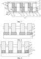
- FIG. 1 is a partial schematic perspective view of the semiconductor structure of an embodiment of the present application.
- FIG. 2 is a partial schematic perspective view of semiconductor channels and gate structures in a semiconductor structure of an embodiment of the present application.
- FIGS. 3 to 7 are five partial schematic top views of semiconductor structures of the embodiments of the present application.
- FIG. 8 is a schematic cross-sectional view of the structure shown in FIG. 3 along the line AA1.
- FIG. 9 is another schematic cross-sectional view of a semiconductor structure of an embodiment of the present application along line AA1.
- FIG. 10 is another partial schematic perspective view of a semiconductor structure of an embodiment of the present application.
- the semiconductor structure comprises semiconductor channels 100 extending in the third direction Z, first gate structures 111, second gate structures 121 and bit lines 102 extending in the second direction Y
- Each semiconductor channel 100 has an L-shaped cross-section in a plane perpendicular to the third direction Z, and comprises a first L-shaped sidewall 110 and a second L-shaped sidewall 120 which are opposite to each other and extend in the third direction Z.
- the first L-shaped sidewall 110 comprises a first face 130 extending in a first direction X and a second face 140 extending in a second direction Y
- Each first gate structure 111 is in contact with the first face 130.
- Each second gate structure 121 is in contact with the second face 140.
- the first gate structures 111 are in contact with the second gate structures 121.
- the combined structure of the first gate structure 111 and a second gate structure 121 has an L-shaped cross-section in a plane perpendicular to the third direction Z.
- Each bit line 102 is located on a side of each of the semiconductor channels 100 in the third direction Z.
- the first direction X, the second direction Y and the third direction Z intersect with each other.
- first gate structure 111 and the second gate structure 121 may be an integrally formed structure. Since the first gate structure 111 and the second gate structure 121 are in contact with each other, the first gate structure 111 and the second gate structure 121 shown in drawings are divided by a dashed line for clarity of drawings.
- a portion connecting the first gate structure 111 and the second gate structure 121 which correspond to a same semiconductor channel 100 has been put under the first gate structure 111. In other embodiments, with reference to FIGS.
- the portion connecting the first gate structure 111 and the second gate structure 121 which correspond to a same semiconductor channel 100 has been put under the second gate structure 121. It can be understood that the portion connecting the first gate structure 111 and the second gate structure 121 which correspond to a same semiconductor channel 100 may be put under the first gate structure 111 or the second gate structure 121, the semiconductor structure of an embodiment of the present application is not limited thereto.
- the semiconductor structure comprises a plurality of the semiconductor channels 100 arranged at intervals in the first direction X, and adjacent semiconductor channels 100 are arranged axisymmetrically.
- the symmetry axis I is a symmetry axis between two adjacent semiconductor channels 100 in the first direction X.
- every two semiconductor channels 100 spaced apart by one semiconductor channel 100 therebetween are able to have a same arrangement orientation in the semiconductor structure.
- the first faces 130 of the semiconductor channels 100 arranged in the first direction X tend to be aligned with each other. Therefore, one gate structure 101 is common to multiple semiconductor channels 100 arranged in the first direction X. It can be understood that the gate structure 101 comprises at least a plurality of the first gate structures 111 and a plurality of the second gate structures 121.
- the gate structures 101 will be described in detail by two embodiments below.
- the semiconductor structure comprises a plurality of the first gate structures 111 and a plurality of the second gate structures 121.
- Each of the first gate structures 111 and each of the second gate structures 121 are in a one-to-one correspondence with the semiconductor channels 100. That is, each first face 130 is in contact with a respective first gate structure 111, and each second face 140 is in contact with a respective second gate structure 121.
- the semiconductor structure may further comprise third gate structures 131 and fourth gate structures 141.
- Each of the third gate structures is in contact with ends of two adjacent second gate structures 121 in the first direction X which are away from the first gate structure 111.
- Each of the fourth gate structures is in contact with ends of two adjacent first gate structures 111 in the first direction X which are away from the second gate structure 121.
- Each of the gate structures 101 is formed by at least one of the first gate structures 111, at least one of the second gate structures 121, at least one of the third gate structures 131 and at least one of the fourth gate structures 141.
- each of the gate structures 101 can form an elongated structure extending in the first direction X and having grooves.
- the first gate structures 111, the second gate structures 121, the third gate structures 131 and the fourth gate structures 141 can be integrally formed at the same time.
- every two adjacent second gate structures 121 and a third gate structure 131 form a U-shaped opening.
- connection relationships between the first gate structures 111 and the semiconductor channels 100 will be described in detail by two embodiments below.
- Each of the semiconductor channels 100 further comprises a third face 150 which is adjacent to the first face 130, and opposite to the second face 140.
- the third face 150 also extends in the third direction Z.
- each of the fourth gate structure 141 is in contact with the respective first gate structures 111, and is also in contact with the respective third faces 150. In this way, the facing area between the gate structure 101 and each semiconductor channel 10 is increased, so as to improve a control capability of the gate structure 101 on the semiconductor channels 100.
- each of the fourth gate structures 141 is in contact with the respective first gate structures 111
- each of the third faces 150 is in contact with a respective one of second isolation layers 123, which will be described in detail later.
- the gate structure 101 may be or may not be in contact with the third faces 150 in the semiconductor structure, which can be flexibly adjusted according to an actual requirement.
- a neighboring pair among the three adjacent semiconductor channels 100 is in contact with a same second gate structure 121, and another neighboring pair among the three adjacent semiconductor channels 100 is in contact with a same first gate structure 111.
- the first gate structures 111 and the second gate structures 121 are alternately arranged in the first direction X.
- Each of the gate structures 101 is formed by at least one of the first gate structures 111 and at least one of the second gate structures 121.
- each second gate structure 121 is in contact with two adjacent second faces 140 in the first direction X, and each first gate structure 111 is in contact with two adjacent first faces 130 in the first direction X.
- each gate structure 101 may form an elongated structure extending in the first direction X and having protrusions.
- the first gate structures 111 and the second gate structures 121 may be formed in one piece. It should be noted that, in an example shown in FIG. 5 , the first gate structure 111 is in contact with respective first faces 130, and in contact with respective third faces 150 and a respective one of the second isolation layers 123. In actual application, each of the first gate structures 111 can be only in contact with the first faces 130 and the second isolation layer 123, and each of the third faces 150 is in contact with and connect to the second isolation layers 123.
- adjacent semiconductor channels 100 arranged at intervals in the first direction X are arranged axisymmetrically.
- a plurality of the semiconductor channels 100 are arranged at intervals in the first direction X.
- a first face 13 0 is provided between two adjacent second faces 140 in the first direction X.
- the of the first gate structures 111 and the second gate structures 121 are in a one-to-one correspondence with the semiconductor channels 100.
- Each of the second gate structures 121 is in contact with two adjacent first gate structures 111 in the first direction.
- Each of the gate structures is formed by at least one of the first gate structures 111 and at least one of the second gate structures 121.
- the semiconductor channels 100 arranged at intervals in the first direction X have a same arrangement orientation, such that the first faces 130 of the semiconductor channels 100 arranged in the first direction X tend to be aligned with each other. Therefore, one gate structure is common to the plurality of semiconductor channels 100 arranged in the first direction X.
- the gate structures 101 will be described in detail by two embodiments below.
- each of the second gate structures 121 is in contact with two adjacent first gate structures 111 in the first direction X, and also in contact with at least the third face 150.
- an area of the gate structure 101 directly facing the respective semiconductor channels 100 can be increased, so as to improve a control capability of the gate structures 101 on the semiconductor channels 100.
- the gate structure 101 may further comprises other gate structures in addition to the first gate structures 111 and the second gate structures 121.
- the specific configuration of the gate structure 101 is not limited.
- each of the first gate structures 111 is in contact with the first face 130, and also in contact with the second isolation layer 123. That is, a length of each of the first gate structures 111 in the first direction X is greater than a length of the semiconductor channel 100 corresponding to this first gate structure 111 in the first direction X. Furthermore, the second isolation layer 123 is in contact with the third face 150. It should be noted that, in the arranging manner of the semiconductor channels 100 shown in FIG. 7 , in a case of the gate structure 101 in contact with the first faces 130 and the second faces 140, the gate structure 101 may further comprises other gate structures in addition to the first gate structures 111 and the second gate structures 121. That is, the specific configuration of the gate structure 101 is not limited.
- the number of semiconductor channels 100 arranged at intervals in the first direction X is not limited, and for example, may be 2, 5, 8 etc.
- the semiconductor structure comprises a plurality of the semiconductor channels 100 arranged at intervals in the second direction Y
- Each of the semiconductor channels 100 arranged at intervals in the second direction Y is in a one-to-one correspondence with the gate structures 101. Spacings are provided between adjacent gate structures 101 in the second direction Y
- each of the semiconductor channels 100 is beneficial to increasing the integration density of the semiconductor channels 100 and increasing the intervals between the adjacent first gate structures 111 in the second direction Y, so as to mitigate the interferences between the adjacent gate structures 101.
- adjacent semiconductor channels 100 in the second direction Y are arranged centrosymmetrically.
- a symmetry point II is a symmetry point of two adjacent semiconductor channels 100 in the second direction Y
- the second gate structures 121 of one of two adjacent gate structures 101 in the second direction Y and second gate structures 121 of the other of two adjacent gate structures 101 in the second direction Y are staggered in the first direction X, so as to increase the spacing between two second gate structures 121 opposite in the second direction Y Therefore, the integration density of the semiconductor channels 100 in the semiconductor structure is improved. Intervals between the first gate structures 111 opposite in the second direction Y are decreased, and intervals between the second gate structures 121 opposite in the second direction Y are also decreased, so as to weaken interferences between adjacent gate structures 101 and improve the electrical performance of the semiconductor structure.
- adjacent semiconductor channels 100 in the second direction Y can be arranged axisymmetrically. That is, the arrangements of the semiconductor channels 100 in the first direction X and in the second direction Y are not limited in the semiconductor structure of an embodiment of the present application, as long as "a same gate structure 101 is common to a plurality of the semiconductor channels 100 are arranged at intervals in the first direction X, each of a plurality of the semiconductor channels 100 arranged at intervals in the second direction Y is in a one-to-one correspondence with the gate structures 101, and intervals are arranged between adjacent gate structure 101 in the second direction Y".
- a single bit line 102 may be in contact with multiple semiconductor channels 100 arranged at intervals in the second direction Y
- the number of the semiconductor channels 100 arranged at intervals in the second direction Y is 2.
- the number of the semiconductor channels 100 arranged at intervals in the second direction Y is 4.
- the number of semiconductor channels 100 arranged at intervals in the second direction Y is not limited, and may be 3, 6, 8, etc.
- the adjacent semiconductor channels 100 in the second direction Y are arranged centrosymmetrically. Every two adjacent semiconductor channels 100 in the second direction Y define a reference structure 160. Two second faces 140 of the reference structure are located in the spacing between two first faces 130.
- the semiconductor structure may further comprises: first isolation layers 113 in contact with two second L-shaped sidewalls 120 of in the reference structure160, and second isolation layers 123 in contact with two second L-shaped sidewalls 120 of a respective one of the reference structures 160, each of the second isolation layers is located between adjacent first isolation layers 113 in the first direction X.
- the first isolation layers 113 are in contact with the second isolation layers 123, and the first isolation layers 113 and the second isolation layers 123 are alternately arranged in the first direction X (i.e. arranged one after another in the first direction X).
- each of the first isolation layers 113 is configured to provide the insulation between two semiconductor channels 100 in contact with this first isolation layer.
- Each of the second isolation layers 123 is configured to provide the insulation between adjacent respective gate structures 101 in the second direction Y and respective semiconductor channels 100.
- each of the first isolation layers 113 can be a rectangular prism with four corners.
- Each of the first isolation layers 113 may be in contact with two semiconductor channels 100.
- every two semiconductor channels 100 corresponding to a same first isolation layer 113 are respectively located at two corners of the first isolation layer 113 which are furthest from each other, so as to increase an overall spacing between the two semiconductor channels 100.
- every two semiconductor channels 100 corresponding to a same first isolation layer 113 may be respectively located at any two corners of the first isolation layer 113.
- the second isolation layers 123 in various embodiments will be described in detail below respectively.
- each of the second isolation layers 123 is located between adjacent first isolation layers 113 in the first direction X, and between two gate structures 101 corresponding to a reference structure 160.
- Each of the second isolation layers 123 is not in contact with or connected to the third face 150, and each of the gate structures 101 is in contact with the third faces 150.
- each of the second isolation layers 123 is located between adjacent first isolation layers 113 in the first direction X, and between two gate structures 101 corresponding to a reference structure 160. Each of the second isolation layers 123 is in contact with the third faces 150
- arrangement of the second isolation layers 123 varies according to that of the gate structures 101, to provide insulation between the adjacent gate structures 101 in the second direction Y and the semiconductor channels 100.
- a length of each of the first isolation layers 113 in the second direction Y is a first length.
- a length of each of the second isolation layers 123 in the second direction Y is a second length.
- a ratio of the second length to the first length ranges from 1/2 to 2/3.
- the ratio of the second length to the first length is greater than or equal to 1/2, every two semiconductor channels 100 in contact with a same first isolation layer 113 do not have regions directly facing each other, thereby reducing the interference between said two semiconductor channels 100, such as the parasitic capacitance between them.
- the ratio of the second length to the first length is less than or equal to 2/3, it is convenient to provide semiconductor channels 100 with a large size, thereby ensuring that gate structure 101 and the semiconductor channels 100 have sufficient areas directly facing each other.
- each of the gate structures 101 comprises a gate dielectric layer 151 and a gate 161.
- the gate dielectric layer 151 is disposed on the first face 130 and second face 140.
- the gate dielectric layer 151 is in a one-to-one correspondence with the semiconductor channels 100.
- the gate dielectric layer 151 has an L-shaped cross-section in a plane perpendicular to the third direction Z.
- the gate 161 is disposed on a side of the gate dielectric layer 151 away from each of the semiconductor channels 100. It can be understood that in an example shown in FIG. 4 , only the first gate structures 111 and the second gate structures 121 comprise the gate dielectric layer 151.
- Each of the third gate structures 131 and the fourth gate structures 141 is formed only by the gate 161. That is, for a single gate structure 101, the gate structure may comprise a plurality of the gate dielectric layers 151 arranged axisymmetrically in the first direction and a gate 161 common to the plurality of gate dielectric layers 151.
- the arrangement manner of the gate dielectric layer 151 and the gate 161 in the gate structures 101 shown in FIG. 4 is also applicable to the examples shown in FIGS. 1 , 3 , and 5 to 7 .
- a same gate dielectric layer 151 may also be common to the plurality of semiconductor channels 100 arranged at intervals in the first direction X while ensuring that the gate dielectric layer 151 is located on the first face 130 and the second face 140,.
- the semiconductor structure further comprises a substrate 106 located on the side of the bit lines 102 away from the semiconductor channels 100.
- bit lines 102 are described in detail below through following embodiments.
- the bit line 102 is a single layer structure.
- an orthographic projection of each semiconductor channel 100 on the substrate 106 is located in an orthographic projection of respective bit line 102 on the substrate 106. That is, an entire bottom surface of each semiconductor channel 100 facing the substrate 106 is in contact with the respective bit line 102, which facilitates increasing a contact area between the bit line 102 and the respective semiconductor channel 100. Therefore a contact resistance between the bit line 102 and the respective semiconductor channel 100 is reduced, so as to improve the electrical performance of the semiconductor structure.
- a material of the bit lines 102 can be a doped semiconductor material, such as a silicon material doped with N-type ions or P-type ions.
- the N-type ions may be at least one of arsenic ions, phosphorus ions or antimony ions
- the P-type ions may be at least one of boron ions, indium ions, or gallium ions.
- each of the bit lines 102 comprises a first sub-bit line 112 and a second sub-bit line 122 which are spaced from each other in the first direction X, the first sub-bit line 112 and the second sub-bit line 122 extend in the second direction Y
- the semiconductor structure further comprises insulation layers 107 each located between the first sub-bit line 112 and the second sub-bit line 122.
- materials of the bit lines 102 comprises at least one of metallic materials such as tungsten, aluminum, titanium, or tantalum, or at least one of conductive materials such as titanium nitride, tantalum nitride, or tungsten nitride.
- a material of the semiconductor channels 100 comprises silicon or silicon germanium.
- the material of the semiconductor channels 100 is silicon germanium, which facilitates improving the carrier mobility of the channel regions in the semiconductor channels 100 through silicon germanium, so as to increase an on/off ratio of a transistor formed by the gate structures 101 and the semiconductor channels 100. Therefore, the electrical performance of the semiconductor structure can be improved.
- the channel region in the semiconductor channel 100 refers to the semiconductor channels 100 in contact with the gate structure 101.
- the semiconductor structure may further comprise capacitive structures 104, each of which at least in contact with a side of the respective semiconductor channel 100 away from the respective bit line 102. It can be understood that each of the capacitive structures 104 is in a one-to-one correspondence with the semiconductor channels 100.
- the integration density of the semiconductor channels 100 in the semiconductor structure is improved. Therefore the integration density of the capacitive structures 104 in the semiconductor structure is also improved.
- FIG. 10 shows the capacitor structures 104 added on the basis of the semiconductor structure of FIG. 1 . It can be understood that in the examples shown in FIGS. 1 to 7 , in case that adjacent capacitive structures 104 are arranged at intervals. The application is not limited to the specific arrangement of the capacitive structures 104, as long as a contact area between the capacitive structure 104 and the side of the respective semiconductor channel 100 away from the substrate 106 is increased as much as possible.
- the semiconductor channel 100 has an L-shaped cross-section in the plane perpendicular to the third direction Y
- the L-shaped cross-section of each of the semiconductor channels 100 is beneficial to decreasing intervals between whole adjacent semiconductor channels 100 while ensuring a larger spacing between opposite parts of the adjacent semiconductor channels 100. Therefore, a larger number of semiconductor channels 100 can be provided in per unit area, so as to improve the integration density of the semiconductor structure.
- larger spacing between the opposite parts of the adjacent semiconductor channels 100 is beneficial to weakening the interference between the adjacent semiconductor channels 100.
- FIGS. 11 to 20 are partial schematic views, each of which corresponds to a respective operation of the manufacturing method of the semiconductor structure of the embodiment of the present application.
- FIGS. 11 to 17 and FIG. 20 are schematic perspective views, each of which corresponds to the respective operation of the manufacturing method of the semiconductor structure.
- FIG. 18 is a schematic cross-sectional view of FIG. 17 along line AA1.
- FIG. 19 is a schematic cross-sectional view corresponding to an operation in the manufacturing method of the semiconductor structure of the embodiment of the present application.
- the manufacturing method of the semiconductor structure comprises an operation of forming semiconductor channels 100 extending in a third direction Z.
- Each semiconductor channel 100 has an L-shaped cross-section in a plane perpendicular to the third direction Z, and comprises a first L-shaped sidewall 110 and a second L-shaped sidewall 120 which are opposite to each other and extend in the third direction Z.
- the first L-shaped sidewall 110 comprises a first face 130 extending in a first direction X and a second face 140 extending in a second direction Y
- the method also comprises an operation of forming first gate structures 111 and second gate structures 121 which are in contact with each other.
- Each first gate structure 111 is in contact with the first face 130, each second gate structure 121 is in contact with the second face 140.
- a combined structure formed by the first gate structure 111 and the second gate structure 121 has an L-shaped cross-section in the plane perpendicular to the third direction Z.
- the method also comprises an operation of forming bit lines 102 extending in the second direction Y and located on a side of the semiconductor channel 100 in the third direction Z.
- the first direction X, the second direction Y and the third direction Z intersect with each other.
- first gate structure 111 and the second gate structure 121 are formed after the formation of the semiconductor channel 100.
- a sequence of the formation of the semiconductor channel 100 and the formation of the bit line 102 is not limited and can be adjusted according to the actual requirement.
- the manufacturing method of the embodiment of the present application comprises but is not limited to specific examples of the manufacturing method for the semiconductor structure in the following description.
- the operation of forming the semiconductor channels 100 may comprise: forming semiconductor columns 105 arranged at intervals in the first direction X and/or the second direction Y
- a material of the semiconductor columns 105 may be a semiconductor material such as silicon or silicon germanium.
- an arrangement manner of the semiconductor columns 105 generally determines an arrangement manner of the semiconductor channels 100. For example, if the semiconductor columns 105 are arranged at intervals in the first direction X, the semiconductor channels 100 are also arranged at intervals in the first direction X; if the semiconductor columns 105 are arranged at intervals in the second direction Y, the semiconductor channels 100 are also arranged at intervals in the second direction Y
- each semiconductor column 105 is arranged at intervals in the first direction X.
- the number of semiconductor columns 105 arranged at intervals in the first direction X is not limited.
- a plurality of the semiconductor columns 105 may also be arranged at intervals in the second direction Y, or a plurality of the semiconductor columns 105 may be arranged at intervals in the first direction X and arranged at intervals in the second direction Y
- the present application is not limited to a specific process for forming the plurality of semiconductor columns 105.
- the bit lines 102 are formed prior to the formation of the semiconductor channels 100 and the gate structures 101, i.e. prior to the formation of the semiconductor columns 105.
- the operation of forming the bit lines 102 may comprise: providing a substrate 106; and forming, bit lines 102 extending in the second direction Y and arranged at intervals in the first direction X, on the substrate 106.
- the substrate 106, the bit lines 102 and the semiconductor columns 105 have same semiconductor chemical elements. Therefore, the substrate 106, the bit lines 102 and the semiconductor columns 105 may be formed by a same film structure composed of the semiconductor chemical elements. Thereby a process for forming the bit lines 102 is simplified.
- a material of the bit lines 102 may be doped semiconductor material, such as silicon material doped with N-type ions or P-type ions.
- the operation of forming the semiconductor channels 100 may comprise: forming the semiconductor channels 100 on a side of the bit lines 102 away from the substrate 106, with a bottom surface of each semiconductor channel 100 facing the substrate 106 being in contact with the respective bit line 102.
- the manufacturing method further comprises: forming first dielectric layers 117 each located between adjacent bit lines 102 to provide the insulation between adjacent bit lines 102.
- the manufacturing method may further comprise: providing a substrate 106; forming an initial insulation layer 127 on the substrate 106.
- the initial insulation layer 127 will be etched to provide spaces for forming the bit lines 102.
- the operation of forming the semiconductor columns 105 may comprise: forming the semiconductor columns 105 on a side of the initial insulation layer 127 away from the substrate 106.
- the semiconductor channels 100 are formed on sidewalls of the semiconductor columns 105 extending in the third direction Z. Every two semiconductor channels 100 in contact with a same semiconductor column 105 are arranged centrosymmetrically, and/or adjacent semiconductor channels 100 in the first direction X are arranged axisymmetrically.
- each of the semiconductor columns 105 may be a rectangular prism with four corners. Each of the semiconductor columns 105 may be in contact with two respective semiconductor channels 100. Furthermore, in an example shown in FIG. 4 , the two semiconductor channels 100 corresponding to a same semiconductor column 105 are respectively located at two corners of the semiconductor column 105 which are furthest from each other, so as to increase an overall spacing between the two semiconductor channels 100. In actual application, the two semiconductor channels 100 corresponding to a same semiconductor column 105 may be respectively located at any two corners of the semiconductor column 105.
- the operation of forming semiconductor channels comprises, but is not limited to, the following embodiments:
- each of the semiconductor columns 105 has a first side 115 and a second side 125 opposite to each other in the second direction Y
- a length of each semiconductor column 105 in the second direction Y is a third length.
- third isolation layers 133 and fourth isolation layers 143 are alternately located between adjacent semiconductor columns 105 in the first direction X.
- One of sidewalls of each third isolation layers 133 which extends in the third direction Z is flush with the first side 115.
- a length of each of the third isolation layers 133 in the second direction Y is less than the third length.
- One of sidewalls of each fourth isolation layers 143 which extends in the third direction Z is flush with the second side 125.
- a length of each of the fourth isolation layers 143 in the second direction Y is less than the third length.
- each of two opposite end surfaces of each third isolation layer 133 in the third direction Z is flush with a respective one of two opposite end surfaces of each semiconductor column 105 in the third direction Z, respectively.
- Each of two opposite end surfaces of each fourth isolation layer 143 in the third direction Z is flush with a respective one of two opposite end surfaces of each semiconductor column 105 in the third direction Z, respectively. It can be understood that, in the third direction Z, top surfaces of the third isolation layers 133, top surfaces of the fourth isolation layers 143 and top surfaces of the semiconductor columns 105 are flush with each other, and bottom surfaces of the third isolation layers 133, bottom surfaces of the fourth isolations layer 143 and bottom surfaces of the semiconductor columns 105 are flush with each other.
- Each of the semiconductor columns 105 has a third side 135 and a fourth side 145 opposite to each other in the first direction X.
- the third side 135 may be divided into a first region and a second region in the second direction Y
- the fourth side 145 may be divided into a third region and a fourth region in the second direction Y
- Each of the third isolation layers 133 may completely cover the first region(s) of the respective semiconductor column(s), and each of the fourth isolation layers 143 may completely cover the fourth region(s) of the respective semiconductor column(s).
- each of the semiconductor channels 100 are formed on parts of sidewalls of the respective semiconductor column 105 extending in the third direction Z which are exposed form the third isolation layer 133 and the fourth isolation layer 143.
- a third L-shaped sidewall may be formed by the first side 115 and the exposed third region
- a fourth L-shaped sidewall may be formed by the second side 125 and the exposed second region.
- One semiconductor channel 100 can be formed based on the third L-shaped sidewall
- another semiconductor channel 100 can be formed based on the fourth L-shaped sidewall.
- the third isolation layers 133 and the fourth isolation layers 143 serve to isolate every two semiconductor channels 100 from one another.
- Each of the second L-shaped sidewalls 120 of the semiconductor channels 100 is in contact with the third L-shaped sidewall or the fourth L-shaped sidewall.
- each of the semiconductor channels 100 may be formed on the exposed parts of the sidewalls of the respective semiconductor column 105 extending in the third direction Z.
- a length of each of the semiconductor columns 105 in the second direction Y is a third length.
- a ratio of the length of each of the third isolation layers 133 in the second direction Y to the third length ranges from 1/2 to 2/3, and/or a ratio of the length of each of the fourth isolation layers 143 in the second direction Y to the third length ranges from 1/2 to 2/3.
- the semiconductor channels 100 are formed based on parts of the sidewalls of the semiconductor columns 105 which are not covered by the third layers 133 and fourth isolation layers 143. Therefore, a size of the semiconductor channel 100 is affected by a size of the third isolation layer 133 and a size of the fourth isolation layer 143.
- the length of the third isolation layer 133 in the second direction Y may be not equal to the length of the fourth isolation layer 143 in the second direction Y, that is, the sizes of two semiconductor channels 100 corresponding to a same semiconductor column 105 may not be identical. In other embodiments, the length of the third isolation layer 133 in the second direction Y may be equal to the length of the fourth isolation layer 143 in the second direction Y
- the ratio of the length of the third isolation layer 133 or the fourth isolation layer 143 in the second direction Y to the third length is greater than or equal to 1/2, so as to avoid that two semiconductor channels 100 in contact with adjacent third isolation layer 133 and fourth isolation layer 143 have regions directly facing each other, thereby reducing the interference between said two semiconductor channels 100, such as parasitic capacitance between them.
- the ratio of the length of the third isolation layer 133 or the fourth isolation layer 143 in the second direction Y to the third length is less than or equal to 2/3, such that each semiconductor channel 100 has a large size, thereby ensuring that the gate structure 101 and the semiconductor channel 100 have sufficient areas directly facing each other.
- the manufacturing method of the embodiment of the present application does not limit a specific process for forming the third isolation layers 133 and the fourth isolation layers 143.
- an initial isolation layer which covers all sidewalls of the semiconductor columns 105 extending in the third direction Z is formed first, and the initial isolation layer is etched to form the third isolation layers 133 and the fourth isolation layers 143.
- spaces occupied by the third isolation layers 133 and fourth isolation layers 143 will be used for forming the first isolation layers 113 (with reference to FIG. 1 ).
- a material of the third isolation layers 133 may be the same as or different from a material of the fourth isolation layers 143.
- the material of the third isolation layers 133 and the material of the fourth isolation layer 143 may both be silicon oxide.
- the operation of forming the semiconductor channels 100 may comprise: forming an initial semiconductor channel (not shown) on four sidewalls of the semiconductor column 105 extending in the third direction Z, then etching the initial semiconductor channel by means of a mask to form the final semiconductor channel.
- a process for forming the initial semiconductor channel may also use the epitaxial growth process.
- the manufacturing method may further comprise: providing the substrate 106; and forming an initial insulation layer 127 on the substrate 106.
- the operation of forming the semiconductor columns 105 comprises: forming the semiconductor columns 105 on a side of the initial insulation layer 127 away from the substrate 106.
- the formation of the bit lines 102 comprises the following.
- the semiconductor columns 105 are removed to form first grooves 108.
- the first isolation layers 133 filled into the first groove 108 are formed.
- the third isolation layers 133 and the fourth isolation layers 143 are removed.
- second dielectric layers 137 are formed, with gaps 118 being provided between the adjacent semiconductor channels 100 in the first direction X.
- the initial insulation layer 127 is etched through the gaps 118 to form second grooves 128. At least a part of the bottom surface of each semiconductor channel 100 facing the substrate 106 is exposed through the second grooves 128. An orthographic projection of each gap 118 on the substrate 108 is located in an orthographic projection of the respective second groove 128 on the substrate 106. Remaining part of the initial insulation layer forms the insulation layers 107.
- the bit lines 102 are formed in the second grooves 128. Each of the bit lines 102 is in contact with at least part of the bottom surfaces of the respective semiconductor channels 100 facing the substrate 106 and exposed through the second groove 128. Each of the bit lines 102 comprises a first sub-bit line 112 and a second sub-bit line 122 which are located respectively on two opposite sides of the insulation layer 107 in the first direction X. The first sub-bit lines 112 and the second sub-bit lines 122 extend in the second direction Y
- the first isolation layers 113 are formed in spaces previously occupied by the third isolation layers 133 and the fourth isolation layers 143. It should be noted that the manufacturing method of the embodiment of the present application does not limit the specific process for forming the first isolation layers 113.
- the operation of forming the first gate structures 111 and the second gate structures 121 may comprise: forming the second isolation layers 123.
- the second isolation layers 123 cover parts of the sidewalls of the first isolation layers 113 extending in the third direction Z and exposed form the semiconductor channels 100.
- Each of the second isolation layers 123 is connected to adjacent first isolation layers in the first direction. It can be understood that the second isolation layers 123 are formed after the third isolation layers 133 (with reference to FIG. 13 ) and the fourth isolation layers 143 (with reference to FIG. 13 ) are removed, that is, the second isolation layers 123 are formed in the spaces previously occupied by the third isolation layers 133 and the fourth isolation layers 143. It should be noted that the manufacturing method of the ebodiment of the present application does not limit the specific process for forming the second isolation layers 123.
- the reference sidewall 109 comprises a first region 119, a second region 129 and a third region 139 arranged successively in the third direction Z.
- the gate structure 101 is formed in the second region 129.
- the gate structure 101 is in contact with a plurality of the semiconductor channels 100 arranged at intervals in the first direction X.
- the gate structure 101 comprises at least the first gate structures 111 and the second gate structures 121.
- FIGS. 13 to 15 do not show structures such as the substrate and the bit lines etc., and the operations shown in FIGS. 13 to 15 are applicable to two cases respectively shown in FIGS. 11 and 12 .
- FIGS. 16 and 20 merely take the substrate 106 and the bit lines 102 shown in FIG. 11 as examples.
- the operations of forming the forming the first isolation layers 113 and the second isolation layers 123 shown in FIGS. 16 and 20 are also applicable to the case shown in FIG. 12 . That is, the process operations of the manufacturing method shown in FIGS. 13 to 16 and FIG. 20 are applicable to both cases respectively shown in FIGS. 11 and 12 .
- the manufacturing method of the embodiment of the present application does not limit the specific process for forming the gate structures 101.
- each semiconductor channel 100 have the L-shaped cross-section in the plane perpendicular to the third direction Y
- the L-shaped cross-section of each of the semiconductor channels 100 is beneficial to decreasing the overall intervals between adjacent semiconductor channels 100 while ensuring larger spacings between opposite parts of the adjacent semiconductor channels 100. Therefore, a larger number of semiconductor channels 100 can be provided in per unit area, so as to improve the integration density of the semiconductor structure.
- larger spacing between the opposite parts of the adjacent semiconductor channels 100 is beneficial to weakening the interference between the adjacent semiconductor channels 100.
Landscapes
- Semiconductor Memories (AREA)
- Engineering & Computer Science (AREA)
- Power Engineering (AREA)
Abstract
Description
- This application claims priority to
Chinese patent application No. 202211357775.5, filed on November 1, 2022 - The present application relates to the field of semiconductor technologies, and in particular to a semiconductor structure and a method for manufacturing the semiconductor structure.
- With the development of semiconductor structures, the critical dimensions of the semiconductor structures are decreasing. However, due to the restriction of lithography machines, there is a limit to the scaling down of the critical dimensions of the semiconductor structures. Therefore, the researchers and practitioners in the semiconductor field are committed to manufacturing a chip with higher storage density by a wafer. In the two-dimensional or planar semiconductor devices, the memory cells are arranged in the horizontal direction. Thus the integration density of the two-dimensional or planar semiconductor device can be determined by the area occupied by a unit memory cell, and the integration density of the two-dimensional or planar semiconductor devices is greatly influenced by the technologies of forming fine patterns, which causes the limitation to the continuous increasing of the integration density of the two-dimensional or planar semiconductor devices. Therefore, the semiconductor devices are developing towards three-dimensional semiconductor devices.
- However, with the increasing of the integration density of the semiconductor structure, the reduced spacing between adjacent memory cells causes that the adjacent memory cells are prone to interfere with each other, thereby leading to a deterioration of the electrical performance of the semiconductor structure. Thus it is difficult to achieve a balance between the integration density and the electrical performance of the semiconductor structure.
- Embodiments of the present application provide a semiconductor structure and a manufacturing method thereof, which are at least beneficial to improving the electrical performance and the integration density of the semiconductor structure at the same time.
- According to some embodiments of the present application, one aspect of the embodiments of the present application provides a semiconductor structure, comprising: semiconductor channels extending in a third direction, first gate structures, second gate structures and bit lines. Each of the semiconductor channels has an L-shaped cross-section in a plane perpendicular to the third direction, each of the semiconductor channels comprises a first L-shaped sidewall and a second L-shaped sidewall which are opposite to each other and extend in the third direction, the first L-shaped sidewall comprises a first face extending in a first direction and a second face extending in a second direction. Each of the first gate structures is in contact with the first face. Each of the second gate structures is in contact with the second face. Each of the first gate structures is in contact with a respective one of the second gate structures, and forms a combined structure together with the respective one of the second gate structures. The combined structure has an L-shaped cross-section in the plane perpendicular to the third direction. The bit lines extend in the second direction and are located on a side of each of the semiconductor channels in the third direction. The first direction, the second direction and the third direction intersect with each other.
- In some embodiments, the semiconductor channels are arranged at intervals in the first direction, and adjacent semiconductor channels are arranged axisymmetrically.
- In some embodiments, each of the first gate structures and each of the second gate structures are in a one-to-one correspondence with the semiconductor channels. The semiconductor structure further comprises third gate structures and fourth gate structures, each of the third gate structures is in contact with ends of two adjacent second gate structures in the first direction, which are away from the respective first gate structure. Each of the fourth gate structures is in contact ends of two adjacent first gate structures in the first direction, which are away from the respective second gate structure. Gate structures are formed in the semiconductor structure, each of gate structures is formed by at least one of the first gate structures, at least one of the second gate structures, at least one of the third gate structures and at least one of the fourth gate structures.
- In some embodiments, for every three adjacent semiconductor channels in the first direction, a neighboring pair among the adjacent semiconductor channels is in contact with a same second gate structure, and another neighboring pair among the adjacent semiconductor channels is in contact with a same first gate structure. The first gate structures and the second gate structures are alternately arranged in the first direction. Each of gate structures is formed by at least one of first gate structures and at least one of the second gate structures.
- In some embodiments, the semiconductor channels are arranged at intervals in the first direction, and only one first face is provided between two adjacent second faces in the first direction, the first gate structures and the second gate structures are in a one-to-one correspondence with the semiconductor channels, each of the second gate structures is in contact with two adjacent first gate structures in the first direction. Each of the gate structures is formed by at least one of the first gate structures and at least one of the second gate structures.
- In some embodiments, the semiconductor channels are arranged at intervals in the first direction and the second direction. The semiconductor channels arranged at intervals in the second direction are in a one-to-one correspondence with the gate structures. Spacings are provided between adjacent gate structures in the second direction.
- In some embodiments, adjacent semiconductor channels in the second direction are arranged centrosymmetrically or axisymmetrically. Each of the bit lines is contact with and connected to the semiconductor channels arranged at intervals in the second direction.
- In some embodiments, adjacent semiconductor channels in the second direction are arranged centrosymmetrically. Every two adjacent semiconductor channels in the second direction define a reference structure. Two second faces of the reference structure are located in the spacing between two first faces. The semiconductor structure further comprises: first isolation layers in contact with both of two second L-shaped sidewalls in the reference structure, and second isolation layers located between adjacent first isolation layers in the first direction. The first isolation layers are in contact with the second isolation layers, and the first isolation layers and the second isolation layers are alternately arranged in the first direction.
- In some embodiments, a length of each one of the first isolation layers in the second direction is a first length. A length of each one of the second isolation layers in the second direction is a second length. A ratio of the second length to the first length ranges from 1/2 to 2/3.
- In some embodiments, each of the gate structures comprises a gate dielectric layer and a gate. The gate dielectric layer is disposed on the first face and the second face. The gate dielectric layer is in a one-to-one correspondence with each one of the semiconductor channels. The gate dielectric layer has an L-shaped cross-section in the plane perpendicular to the third direction. The gate is disposed on a side of the gate dielectric layer away from each one of the semiconductor channels.
- In some embodiments, each of the bit lines comprises a first sub-bit line and a second sub-bit line which are spaced from each other in the first direction and extend in the second direction. The semiconductor structure further comprises insulation layers each located between the first sub-bit line and the second sub-bit line.
- In some embodiments, a material of the semiconductor channel comprises silicon or silicon germanium.
- In some embodiments, the semiconductor structure further comprises capacitive structures, each of the capacitive structures is at least in contact with a side of the respective semiconductor channel away from the bit lines in the third direction.
- According to some embodiments of the present application, another aspect of the embodiments of the present application provides a manufacturing method for a semiconductor structure, comprising operations of: forming semiconductor channels extending in a third direction, in which each of the semiconductor channels has an L-shaped cross-section in a plane perpendicular to the third direction, each of the semiconductor channels comprises a first L-shaped sidewall and a second L-shaped sidewall which are opposite to each other and extend in the third direction, the first L-shaped sidewall comprises a first face extending in a first direction and a second face extending in a second direction; forming first gate structures and second gate structures which are in contact with each other, in which each of the first gate structure is in contact with the first face, each of the second gate structure is in contact with the second face, and forms a combined structure together with a respective one of the second gate structures, the combined structure has an L-shaped cross-section in the plane perpendicular to the third direction; and forming bit lines extending in the second direction and located on a side of each of the semiconductor channels in the third direction. The first direction, the second direction and the third direction intersect with each other.
- In some embodiments, the operation of forming the semiconductor channels comprising operations of : forming semiconductor columns arranged at intervals in the first direction and/or the second direction; forming the semiconductor channels on sidewalls of the semiconductor columns extending in the third direction, with each of the semiconductor columns being in contact with two respective semiconductor channels, wherein every two semiconductor channels in contact with a same semiconductor column are arranged centrosymmetrically, and/or the adjacent semiconductor channels in the first direction are arranged axisymmetrically.
- In some embodiments, each of the semiconductor columns has a first side and a second side opposite to each other in the second direction. A length of each of the semiconductor columns in the second direction is a third length. After the semiconductor columns are formed and before the semiconductor channels are formed, the manufacturing method further comprises operations of: forming third isolation layers and fourth isolation layers alternately located between adjacent semiconductor columns in the first direction, in which one of sidewalls of each third isolation layer which extends in the third direction is aligned with the first sides, a length of each of the third isolation layers in the second direction is less than the third length, one of sidewalls of each fourth isolation layer which extends in the third direction is aligned with the second sides, a length of each of the fourth isolation layers in the second direction is less than the third length; and forming the semiconductor channels on parts of sidewalls of the semiconductor columns extending in the third direction which are exposed by the third isolation layers and the fourth isolation layers.
- In some embodiments, a ratio of the length of each of the third isolation layers in the second direction to the third length ranges from 1/2 to 2/3, and/or a ratio of the length of each of the fourth isolation layers in the second direction to the third length ranges from 1/2 to 2/3.
- In some embodiments, before the semiconductor columns are formed, the manufacturing method comprises: providing a substrate; and forming an initial insulation layer on the substrate. The operation of forming the semiconductor columns comprises: forming the semiconductor columns on a side of the initial insulation layer away from the substrate. After the semiconductor channels are formed, the operation of forming the bit lines comprises: removing the semiconductor columns to form first grooves, and forming first isolation layers filled in the first grooves; removing the third isolation layers and the fourth isolation layers; etching the initial insulation layer through gaps provided between the adjacent semiconductor channels in the first direction, to form second grooves, at least parts of bottom surfaces of the semiconductor channels facing the substrate are exposed from the second grooves, an orthographic projection of each gap on the substrate is located in an orthographic projection of a respective one of the second grooves on the substrate, remaining parts of the initial insulation layer form insulation layers; and forming the bit lines in the second grooves, with the bit lines being in contact with at least part of bottom surfaces of the semiconductor channels facing the substrate and exposed through the second groove, each of the bit lines comprises a first sub-bit line and a second sub-bit line which are located respectively on two opposite sides of the respective insulation layer in the first direction, the first sub-bit lines and the second sub-bit lines extend in the second direction.
- In some embodiments, after the semiconductor channels are formed, the forming the first gate structures and the second gate structures comprises: forming second isolation layers covering parts of sidewalls of the first isolation layers extending in the third direction and exposed from the semiconductor channels, with each of the second isolation layers being connected to adjacent first isolation layers in the first direction, sidewalls of the semiconductor channels and the first isolation layers which extend in the third direction together form a reference sidewall, the reference sidewall comprises a first region, a second region and a third region arranged in sequence in the third direction; and forming gate structures located in the second region, with each of the gate structures being in contact with a plurality of the semiconductor channels arranged at intervals in the first direction, each of the gate structures comprises at least the first gate structures and the second gate structures.
- In some embodiments, the bit lines are formed before the semiconductor channels and the gate structures are formed, and the operation of forming the bit lines comprises: providing a substrate and forming the bit lines on the substrate, with the bit lines extending in the second direction and being arranged at intervals in the first direction. The operation of forming the semiconductor channels comprises: forming the semiconductor channels on sides of the bit lines away from the substrate, with a bottom surface of each semiconductor channel facing the substrate being in contact with a respective one of the bit lines.
- One or more embodiments are exemplified by the figures in the corresponding drawings, and these exemplary descriptions do not constitute limitations of the embodiments. Unless otherwise stated, the figures in the drawings do not constitute a scale limitation. In order to illustrate the technical solutions in the embodiments of the application or conventional technologies more clearly, the drawings used in the embodiments will be briefly described below. It is apparent that the drawings in the following descriptions are merely some embodiments of the application. Other drawings can be assumed by those skilled in the art according to these drawings without any creative work.
-
FIG. 1 is a partial schematic perspective view of a semiconductor structure of an embodiment of the present application; -
FIG. 2 is a partial schematic perspective view of semiconductor channels and gate structures in a semiconductor structure of an embodiment of the present application; -
FIGS. 3 to 7 are five partial schematic top views of an semiconductor structure of an embodiment of the present application; -
FIG. 8 is a schematic cross-sectional view of the structure shown inFIG. 3 along line AA1; -
FIG. 9 is another schematic cross-sectional view of a semiconductor structure of an embodiment of the present application along line AA1; -
FIG. 10 is another partial schematic perspective view of a semiconductor structure of an embodiment of the present application; -
FIGS. 11 to 20 are partial schematic views, each of which corresponds to a respective operation of the method for manufacturing the semiconductor structure of the present application. - The embodiments of the present application provide a semiconductor structure and a manufacturing method thereof. In the semiconductor structure, a cross-section of a semiconductor channel is L-shaped in a plane perpendicular to a third direction. In this way, in case that a plurality of semiconductor channels are arranged, the L-shaped cross-section of each of the semiconductor channels is beneficial to decreasing the intervals between adjacent semiconductor channels while ensuring the larger spacings between corresponding parts of the adjacent semiconductor channels. Therefore, more semiconductor channels can be provided in unit area, so as to improve the integration density of the semiconductor structure. Moreover, larger spacings between the opposite parts of the adjacent semiconductor channels are beneficial to weakening interferences between the adjacent semiconductor channels. In the subsequent combined structure of the first and second gate structures formed based on first L-shaped sidewalls of the semiconductor channels, larger spacings between opposite parts of the adjacent combined structures can be obtained, so as to weaken the interferences between the adjacent combined structures. Therefore, the electrical performance of the semiconductor structure is improved.
- Each embodiment of the present application will be described in detail below with reference to the drawings. However those skilled in the art will appreciate that in the each embodiment of the present application, numerous technical details are presented for a better understanding of the present application. However, even without these technical details and various variations and modifications based on the following embodiments, technical solutions claimed by the embodiments of the present application may also be realized.
- An embodiment of the present application provides a semiconductor structure, which will be described in detail with reference to the drawings.
FIG. 1 is a partial schematic perspective view of the semiconductor structure of an embodiment of the present application.FIG. 2 is a partial schematic perspective view of semiconductor channels and gate structures in a semiconductor structure of an embodiment of the present application.FIGS. 3 to 7 are five partial schematic top views of semiconductor structures of the embodiments of the present application.FIG. 8 is a schematic cross-sectional view of the structure shown inFIG. 3 along the line AA1.FIG. 9 is another schematic cross-sectional view of a semiconductor structure of an embodiment of the present application along line AA1.FIG. 10 is another partial schematic perspective view of a semiconductor structure of an embodiment of the present application. - With Reference to
FIGS. 1 to 10 , the semiconductor structure comprisessemiconductor channels 100 extending in the third direction Z,first gate structures 111,second gate structures 121 andbit lines 102 extending in the second direction Y Eachsemiconductor channel 100 has an L-shaped cross-section in a plane perpendicular to the third direction Z, and comprises a first L-shapedsidewall 110 and a second L-shapedsidewall 120 which are opposite to each other and extend in the third direction Z. The first L-shapedsidewall 110 comprises afirst face 130 extending in a first direction X and asecond face 140 extending in a second direction Y Eachfirst gate structure 111 is in contact with thefirst face 130. Eachsecond gate structure 121 is in contact with thesecond face 140. Thefirst gate structures 111 are in contact with thesecond gate structures 121. The combined structure of thefirst gate structure 111 and asecond gate structure 121 has an L-shaped cross-section in a plane perpendicular to the third direction Z. Eachbit line 102 is located on a side of each of thesemiconductor channels 100 in the third direction Z. The first direction X, the second direction Y and the third direction Z intersect with each other. - It should be noted that the
first gate structure 111 and thesecond gate structure 121 may be an integrally formed structure. Since thefirst gate structure 111 and thesecond gate structure 121 are in contact with each other, thefirst gate structure 111 and thesecond gate structure 121 shown in drawings are divided by a dashed line for clarity of drawings. When dividing thefirst gate structure 111 and thesecond gate structure 121, in some embodiments, with reference toFIGS. 1 to 4 andFIG. 7 , a portion connecting thefirst gate structure 111 and thesecond gate structure 121 which correspond to asame semiconductor channel 100 has been put under thefirst gate structure 111. In other embodiments, with reference toFIGS. 5 and 6 , the portion connecting thefirst gate structure 111 and thesecond gate structure 121 which correspond to asame semiconductor channel 100 has been put under thesecond gate structure 121. It can be understood that the portion connecting thefirst gate structure 111 and thesecond gate structure 121 which correspond to asame semiconductor channel 100 may be put under thefirst gate structure 111 or thesecond gate structure 121, the semiconductor structure of an embodiment of the present application is not limited thereto. - Embodiments of the present application will be described in more detail below with reference to the drawings.
- With reference to
FIGS. 1-5 , in some embodiments, the semiconductor structure comprises a plurality of thesemiconductor channels 100 arranged at intervals in the first direction X, andadjacent semiconductor channels 100 are arranged axisymmetrically. The symmetry axis I is a symmetry axis between twoadjacent semiconductor channels 100 in the first direction X. In this way, among the plurality ofsemiconductor channels 100 arranged in the first direction X, every twosemiconductor channels 100 spaced apart by onesemiconductor channel 100 therebetween are able to have a same arrangement orientation in the semiconductor structure. In addition, the first faces 130 of thesemiconductor channels 100 arranged in the first direction X tend to be aligned with each other. Therefore, onegate structure 101 is common tomultiple semiconductor channels 100 arranged in the first direction X. It can be understood that thegate structure 101 comprises at least a plurality of thefirst gate structures 111 and a plurality of thesecond gate structures 121. - On a premise that the plurality of
semiconductor channels 100 are arranged at intervals in the first direction X, andadjacent semiconductor channels 100 are arranged axisymmetrically, thegate structures 101 will be described in detail by two embodiments below. - In some embodiments, with reference to
FIGS. 1 ,3, and 4 , the semiconductor structure comprises a plurality of thefirst gate structures 111 and a plurality of thesecond gate structures 121. Each of thefirst gate structures 111 and each of thesecond gate structures 121 are in a one-to-one correspondence with thesemiconductor channels 100. That is, eachfirst face 130 is in contact with a respectivefirst gate structure 111, and eachsecond face 140 is in contact with a respectivesecond gate structure 121. - The semiconductor structure may further comprise
third gate structures 131 andfourth gate structures 141. Each of the third gate structures is in contact with ends of two adjacentsecond gate structures 121 in the first direction X which are away from thefirst gate structure 111. Each of the fourth gate structures is in contact with ends of two adjacentfirst gate structures 111 in the first direction X which are away from thesecond gate structure 121. Each of thegate structures 101 is formed by at least one of thefirst gate structures 111, at least one of thesecond gate structures 121, at least one of thethird gate structures 131 and at least one of thefourth gate structures 141. - It can be understood that each of the
gate structures 101, as a whole, can form an elongated structure extending in the first direction X and having grooves. Thefirst gate structures 111, thesecond gate structures 121, thethird gate structures 131 and thefourth gate structures 141 can be integrally formed at the same time. For asingle gate structure 101, every two adjacentsecond gate structures 121 and athird gate structure 131 form a U-shaped opening. - It should be noted that the connection relationships between the
first gate structures 111 and thesemiconductor channels 100 will be described in detail by two embodiments below. - Each of the
semiconductor channels 100 further comprises athird face 150 which is adjacent to thefirst face 130, and opposite to thesecond face 140. Thethird face 150 also extends in the third direction Z. - In an example, with reference to
FIGS. 1 and3 , each of thefourth gate structure 141 is in contact with the respectivefirst gate structures 111, and is also in contact with the respective third faces 150. In this way, the facing area between thegate structure 101 and each semiconductor channel 10 is increased, so as to improve a control capability of thegate structure 101 on thesemiconductor channels 100. - In another example, with reference to
FIG. 4 , in a case that each of thefourth gate structures 141 is in contact with the respectivefirst gate structures 111, each of the third faces 150 is in contact with a respective one of second isolation layers 123, which will be described in detail later. - It can be understood that the
gate structure 101 may be or may not be in contact with the third faces 150 in the semiconductor structure, which can be flexibly adjusted according to an actual requirement. - In some other embodiments, with reference to
FIG. 5 , for every threeadjacent semiconductor channels 100 in the first direction X, a neighboring pair among the threeadjacent semiconductor channels 100 is in contact with a samesecond gate structure 121, and another neighboring pair among the threeadjacent semiconductor channels 100 is in contact with a samefirst gate structure 111. Thefirst gate structures 111 and thesecond gate structures 121 are alternately arranged in the first direction X. Each of thegate structures 101 is formed by at least one of thefirst gate structures 111 and at least one of thesecond gate structures 121. - It can be understood that each
second gate structure 121 is in contact with two adjacentsecond faces 140 in the first direction X, and eachfirst gate structure 111 is in contact with two adjacentfirst faces 130 in the first direction X. In addition, eachgate structure 101 may form an elongated structure extending in the first direction X and having protrusions. Thefirst gate structures 111 and thesecond gate structures 121 may be formed in one piece. It should be noted that, in an example shown inFIG. 5 , thefirst gate structure 111 is in contact with respectivefirst faces 130, and in contact with respectivethird faces 150 and a respective one of the second isolation layers 123. In actual application, each of thefirst gate structures 111 can be only in contact with the first faces 130 and thesecond isolation layer 123, and each of the third faces 150 is in contact with and connect to the second isolation layers 123. - It should be noted that, in the example shown in
FIG. 5 ,adjacent semiconductor channels 100 arranged at intervals in the first direction X are arranged axisymmetrically. Thus there may be only onesecond gate structure 121 or only onefirst gate structure 111 between every two adjacentsecond faces 140 in the first direction X. That is, there may be nofirst face 130 or there may be twofirst faces 130 located between the adjacentsecond faces 140 in the first direction X. - In some embodiments, with reference to
FIGS. 6 and7 , a plurality of thesemiconductor channels 100 are arranged at intervals in the first direction X. Afirst face 13 0 is provided between two adjacentsecond faces 140 in the first direction X. The of thefirst gate structures 111 and thesecond gate structures 121 are in a one-to-one correspondence with thesemiconductor channels 100. Each of thesecond gate structures 121 is in contact with two adjacentfirst gate structures 111 in the first direction. Each of the gate structures is formed by at least one of thefirst gate structures 111 and at least one of thesecond gate structures 121. - It can be understood that, in examples shown in
FIGS. 6 and7 , thesemiconductor channels 100 arranged at intervals in the first direction X have a same arrangement orientation, such that the first faces 130 of thesemiconductor channels 100 arranged in the first direction X tend to be aligned with each other. Therefore, one gate structure is common to the plurality ofsemiconductor channels 100 arranged in the first direction X. - On a premise that the plurality of
semiconductor channels 100 are arranged at intervals in the first direction X, andadjacent semiconductor channels 100 are not arranged axisymmetrically, thegate structures 101 will be described in detail by two embodiments below. - In an example, with reference to
FIG. 6 , each of thesecond gate structures 121 is in contact with two adjacentfirst gate structures 111 in the first direction X, and also in contact with at least thethird face 150. In this way, an area of thegate structure 101 directly facing therespective semiconductor channels 100 can be increased, so as to improve a control capability of thegate structures 101 on thesemiconductor channels 100. It should be noted that in the example shown inFIG. 6 , there is an interval space between thesecond face 140 of one of twoadjacent semiconductor channels 100 and thethird face 150 of the other of the twoadjacent semiconductor channels 100, and the interval space is filled by the respectivesecond gate structure 121. In actual application, in the arranging manner of thesemiconductor channels 100 shown inFIG. 6 , and in a case of thegate structure 101 in contact with the first faces 130, the second faces 140 and the third faces 150, thegate structure 101 may further comprises other gate structures in addition to thefirst gate structures 111 and thesecond gate structures 121. The specific configuration of thegate structure 101 is not limited. - In another example, with reference to
FIG. 7 , each of thefirst gate structures 111 is in contact with thefirst face 130, and also in contact with thesecond isolation layer 123. That is, a length of each of thefirst gate structures 111 in the first direction X is greater than a length of thesemiconductor channel 100 corresponding to thisfirst gate structure 111 in the first direction X. Furthermore, thesecond isolation layer 123 is in contact with thethird face 150. It should be noted that, in the arranging manner of thesemiconductor channels 100 shown inFIG. 7 , in a case of thegate structure 101 in contact with the first faces 130 and the second faces 140, thegate structure 101 may further comprises other gate structures in addition to thefirst gate structures 111 and thesecond gate structures 121. That is, the specific configuration of thegate structure 101 is not limited. - It should be noted that in the example shown in
FIG. 1 andFIGS 3 to 7 , there are 4semiconductor channels 100 arranged at intervals in the first direction X. In actual application, the number ofsemiconductor channels 100 arranged at intervals in the first direction X is not limited, and for example, may be 2, 5, 8 etc. - In the above embodiments, with reference to
FIG. 1 andFIGS 3 to 7 , the semiconductor structure comprises a plurality of thesemiconductor channels 100 arranged at intervals in the second direction Y Each of thesemiconductor channels 100 arranged at intervals in the second direction Y is in a one-to-one correspondence with thegate structures 101. Spacings are provided betweenadjacent gate structures 101 in the second direction Y - It can be understood that the L-shape of each of the
semiconductor channels 100 is beneficial to increasing the integration density of thesemiconductor channels 100 and increasing the intervals between the adjacentfirst gate structures 111 in the second direction Y, so as to mitigate the interferences between theadjacent gate structures 101. - In some embodiments, with reference to
FIGS. 1 and3-7 ,adjacent semiconductor channels 100 in the second direction Y are arranged centrosymmetrically. A symmetry point II is a symmetry point of twoadjacent semiconductor channels 100 in the second direction Y - It can be understood that, as the
adjacent semiconductor channels 100 in the second direction Y are arranged centrosymmetrically, twosecond faces 140 of some ofadjacent semiconductor channels 100 in the second direction Y are located between two respectivefirst faces 130 due to the L-shapes of thesemiconductor channels 100, such that twosecond gate structures 121 corresponding to twosemiconductor channels 100 adjacent in the second direction Y are located between the two respective first faces 130. Thereby overall spaces occupied byadjacent semiconductor channels 100 in the second direction Y in the semiconductor structure are reduced, and an integration density of thesemiconductor channels 100 is improved. In addition, with reference toFIGS. 1 and3 to 5,semiconductor channels 100 adjacent in the first direction X are arranged axisymmetrically andsemiconductor channels 100 adjacent in the second direction Y are arranged centrosymmetrical. Thus, thesecond gate structures 121 of one of twoadjacent gate structures 101 in the second direction Y andsecond gate structures 121 of the other of twoadjacent gate structures 101 in the second direction Y are staggered in the first direction X, so as to increase the spacing between twosecond gate structures 121 opposite in the second direction Y Therefore, the integration density of thesemiconductor channels 100 in the semiconductor structure is improved. Intervals between thefirst gate structures 111 opposite in the second direction Y are decreased, and intervals between thesecond gate structures 121 opposite in the second direction Y are also decreased, so as to weaken interferences betweenadjacent gate structures 101 and improve the electrical performance of the semiconductor structure. - In actual application,
adjacent semiconductor channels 100 in the second direction Y can be arranged axisymmetrically. That is, the arrangements of thesemiconductor channels 100 in the first direction X and in the second direction Y are not limited in the semiconductor structure of an embodiment of the present application, as long as "asame gate structure 101 is common to a plurality of thesemiconductor channels 100 are arranged at intervals in the first direction X, each of a plurality of thesemiconductor channels 100 arranged at intervals in the second direction Y is in a one-to-one correspondence with thegate structures 101, and intervals are arranged betweenadjacent gate structure 101 in the second direction Y". - In above embodiments with reference to
FIGS. 1 ,3 ,5 and 6 , asingle bit line 102 may be in contact withmultiple semiconductor channels 100 arranged at intervals in the second direction Y - It should be noted that in examples in
FIGS. 1 ,4 , and7 , the number of thesemiconductor channels 100 arranged at intervals in the second direction Y is 2. InFIGS. 3 ,5, and 6 , the number of thesemiconductor channels 100 arranged at intervals in the second direction Y is 4. In actual application, the number ofsemiconductor channels 100 arranged at intervals in the second direction Y is not limited, and may be 3, 6, 8, etc. - In above embodiments with reference to
FIGS. 1 andFIGS 3 to 7 , theadjacent semiconductor channels 100 in the second direction Y are arranged centrosymmetrically. Every twoadjacent semiconductor channels 100 in the second direction Y define areference structure 160. Twosecond faces 140 of the reference structure are located in the spacing between two first faces 130. The semiconductor structure may further comprises: first isolation layers 113 in contact with two second L-shapedsidewalls 120 of in the reference structure160, and second isolation layers 123 in contact with two second L-shapedsidewalls 120 of a respective one of thereference structures 160, each of the second isolation layers is located between adjacent first isolation layers 113 in the first direction X. The first isolation layers 113 are in contact with the second isolation layers 123, and the first isolation layers 113 and the second isolation layers 123 are alternately arranged in the first direction X (i.e. arranged one after another in the first direction X). - In the semiconductor structure, each of the first isolation layers 113 is configured to provide the insulation between two
semiconductor channels 100 in contact with this first isolation layer. Each of the second isolation layers 123 is configured to provide the insulation between adjacentrespective gate structures 101 in the second direction Y andrespective semiconductor channels 100. - It can be understood that each of the first isolation layers 113 can be a rectangular prism with four corners. Each of the first isolation layers 113 may be in contact with two
semiconductor channels 100. In the examples shown inFIGS. 1 to 7 , every twosemiconductor channels 100 corresponding to a samefirst isolation layer 113 are respectively located at two corners of thefirst isolation layer 113 which are furthest from each other, so as to increase an overall spacing between the twosemiconductor channels 100. In actual application, every twosemiconductor channels 100 corresponding to a samefirst isolation layer 113 may be respectively located at any two corners of thefirst isolation layer 113. - The second isolation layers 123 in various embodiments will be described in detail below respectively.
- In some embodiments, with reference to
FIGS. 1 ,3 ,5, and 6 , each of the second isolation layers 123 is located between adjacent first isolation layers 113 in the first direction X, and between twogate structures 101 corresponding to areference structure 160. Each of the second isolation layers 123 is not in contact with or connected to thethird face 150, and each of thegate structures 101 is in contact with the third faces 150. - In other embodiments, with reference to
FIGS. 4 and7 , each of the second isolation layers 123 is located between adjacent first isolation layers 113 in the first direction X, and between twogate structures 101 corresponding to areference structure 160. Each of the second isolation layers 123 is in contact with the third faces 150 - It can be understood that arrangement of the second isolation layers 123 varies according to that of the
gate structures 101, to provide insulation between theadjacent gate structures 101 in the second direction Y and thesemiconductor channels 100. - In some embodiments, with reference to
FIGS. 1 ,3 , and5 , a length of each of the first isolation layers 113 in the second direction Y is a first length. A length of each of the second isolation layers 123 in the second direction Y is a second length. A ratio of the second length to the first length ranges from 1/2 to 2/3. On the one hand, since the ratio of the second length to the first length is greater than or equal to 1/2, every twosemiconductor channels 100 in contact with a samefirst isolation layer 113 do not have regions directly facing each other, thereby reducing the interference between said twosemiconductor channels 100, such as the parasitic capacitance between them. On the other hand, since the ratio of the second length to the first length is less than or equal to 2/3, it is convenient to providesemiconductor channels 100 with a large size, thereby ensuring thatgate structure 101 and thesemiconductor channels 100 have sufficient areas directly facing each other. - In some embodiments, with reference to
FIG. 4 , each of thegate structures 101 comprises agate dielectric layer 151 and agate 161. Thegate dielectric layer 151 is disposed on thefirst face 130 andsecond face 140. Thegate dielectric layer 151 is in a one-to-one correspondence with thesemiconductor channels 100. Thegate dielectric layer 151 has an L-shaped cross-section in a plane perpendicular to the third direction Z. Thegate 161 is disposed on a side of thegate dielectric layer 151 away from each of thesemiconductor channels 100. It can be understood that in an example shown inFIG. 4 , only thefirst gate structures 111 and thesecond gate structures 121 comprise thegate dielectric layer 151. Each of thethird gate structures 131 and thefourth gate structures 141 is formed only by thegate 161. That is, for asingle gate structure 101, the gate structure may comprise a plurality of the gatedielectric layers 151 arranged axisymmetrically in the first direction and agate 161 common to the plurality of gate dielectric layers 151. - It should be noted that the arrangement manner of the
gate dielectric layer 151 and thegate 161 in thegate structures 101 shown inFIG. 4 is also applicable to the examples shown inFIGS. 1 ,3 , and5 to 7 . In addition, in actual application, a samegate dielectric layer 151 may also be common to the plurality ofsemiconductor channels 100 arranged at intervals in the first direction X while ensuring that thegate dielectric layer 151 is located on thefirst face 130 and thesecond face 140,. - The semiconductor structure further comprises a
substrate 106 located on the side of thebit lines 102 away from thesemiconductor channels 100. - The bit lines 102 are described in detail below through following embodiments.
- In some embodiments, with reference to
FIG. 8 , for asingle bit line 102, thebit line 102 is a single layer structure. In addition, an orthographic projection of eachsemiconductor channel 100 on thesubstrate 106 is located in an orthographic projection ofrespective bit line 102 on thesubstrate 106. That is, an entire bottom surface of eachsemiconductor channel 100 facing thesubstrate 106 is in contact with therespective bit line 102, which facilitates increasing a contact area between thebit line 102 and therespective semiconductor channel 100. Therefore a contact resistance between thebit line 102 and therespective semiconductor channel 100 is reduced, so as to improve the electrical performance of the semiconductor structure. In an example, a material of thebit lines 102 can be a doped semiconductor material, such as a silicon material doped with N-type ions or P-type ions. Specifically, the N-type ions may be at least one of arsenic ions, phosphorus ions or antimony ions, and the P-type ions may be at least one of boron ions, indium ions, or gallium ions. - In other embodiments, with reference to
FIG. 9 , each of the bit lines 102 comprises a firstsub-bit line 112 and a secondsub-bit line 122 which are spaced from each other in the first direction X, the firstsub-bit line 112 and the secondsub-bit line 122 extend in the second direction Y The semiconductor structure further comprises insulation layers 107 each located between the firstsub-bit line 112 and the secondsub-bit line 122. In an example, materials of the bit lines 102 comprises at least one of metallic materials such as tungsten, aluminum, titanium, or tantalum, or at least one of conductive materials such as titanium nitride, tantalum nitride, or tungsten nitride. - In some embodiments, a material of the
semiconductor channels 100 comprises silicon or silicon germanium. In an example, the material of thesemiconductor channels 100 is silicon germanium, which facilitates improving the carrier mobility of the channel regions in thesemiconductor channels 100 through silicon germanium, so as to increase an on/off ratio of a transistor formed by thegate structures 101 and thesemiconductor channels 100. Therefore, the electrical performance of the semiconductor structure can be improved. The channel region in thesemiconductor channel 100 refers to thesemiconductor channels 100 in contact with thegate structure 101. - In some embodiments, with reference to
FIG. 10 , the semiconductor structure may further comprise capacitive structures 104, each of which at least in contact with a side of therespective semiconductor channel 100 away from therespective bit line 102. It can be understood that each of the capacitive structures 104 is in a one-to-one correspondence with thesemiconductor channels 100. In examples shown inFIGS. 1 to 7 , the integration density of thesemiconductor channels 100 in the semiconductor structure is improved. Therefore the integration density of the capacitive structures 104 in the semiconductor structure is also improved. - It should be noted that
FIG. 10 shows the capacitor structures 104 added on the basis of the semiconductor structure ofFIG. 1 . It can be understood that in the examples shown inFIGS. 1 to 7 , in case that adjacent capacitive structures 104 are arranged at intervals. The application is not limited to the specific arrangement of the capacitive structures 104, as long as a contact area between the capacitive structure 104 and the side of therespective semiconductor channel 100 away from thesubstrate 106 is increased as much as possible. - To sum up, the
semiconductor channel 100 has an L-shaped cross-section in the plane perpendicular to the third direction Y In this way, in case that a plurality ofsemiconductor channels 100 are arranged, the L-shaped cross-section of each of thesemiconductor channels 100 is beneficial to decreasing intervals between wholeadjacent semiconductor channels 100 while ensuring a larger spacing between opposite parts of theadjacent semiconductor channels 100. Therefore, a larger number ofsemiconductor channels 100 can be provided in per unit area, so as to improve the integration density of the semiconductor structure. Moreover, larger spacing between the opposite parts of theadjacent semiconductor channels 100 is beneficial to weakening the interference between theadjacent semiconductor channels 100. In the combined structures of thefirst gate structures 111 and thesecond gate structures 121 formed based on the first L-shapedsidewalls 110 of thesemiconductor channels 100, larger spacing between opposite parts of the adjacent combined structures can be obtained, so as to weaken interferences between the adjacent combined structures. Therefore, the electrical performance of the semiconductor structure is improved. - Another embodiment of the present application further provides a manufacturing method of a semiconductor structure, which is used for manufacturing the semiconductor structure of the above embodiments. The manufacturing method of the semiconductor structure of another embodiment of the present application will be described in detail below with reference to
FIGS. 1 to 20 .FIGS. 11 to 20 are partial schematic views, each of which corresponds to a respective operation of the manufacturing method of the semiconductor structure of the embodiment of the present application. - It should be noted that identical or corresponding parts with above embodiments will not be repeated here.
FIGS. 11 to 17 andFIG. 20 are schematic perspective views, each of which corresponds to the respective operation of the manufacturing method of the semiconductor structure.FIG. 18 is a schematic cross-sectional view ofFIG. 17 along line AA1.FIG. 19 is a schematic cross-sectional view corresponding to an operation in the manufacturing method of the semiconductor structure of the embodiment of the present application. - With reference to
FIG. 1 to FIG. 20 , the manufacturing method of the semiconductor structure comprises an operation of formingsemiconductor channels 100 extending in a third direction Z. Eachsemiconductor channel 100 has an L-shaped cross-section in a plane perpendicular to the third direction Z, and comprises a first L-shapedsidewall 110 and a second L-shapedsidewall 120 which are opposite to each other and extend in the third direction Z. The first L-shapedsidewall 110 comprises afirst face 130 extending in a first direction X and asecond face 140 extending in a second direction Y The method also comprises an operation of formingfirst gate structures 111 andsecond gate structures 121 which are in contact with each other. Eachfirst gate structure 111 is in contact with thefirst face 130, eachsecond gate structure 121 is in contact with thesecond face 140. A combined structure formed by thefirst gate structure 111 and thesecond gate structure 121 has an L-shaped cross-section in the plane perpendicular to the third direction Z. The method also comprises an operation of formingbit lines 102 extending in the second direction Y and located on a side of thesemiconductor channel 100 in the third direction Z. The first direction X, the second direction Y and the third direction Z intersect with each other. - It should be noted that the
first gate structure 111 and thesecond gate structure 121 are formed after the formation of thesemiconductor channel 100. In another embodiment of the present application, a sequence of the formation of thesemiconductor channel 100 and the formation of thebit line 102 is not limited and can be adjusted according to the actual requirement. The manufacturing method of the embodiment of the present application comprises but is not limited to specific examples of the manufacturing method for the semiconductor structure in the following description. - In some embodiments, with reference to
FIG. 11 orFIG. 12 , the operation of forming thesemiconductor channels 100 may comprise: formingsemiconductor columns 105 arranged at intervals in the first direction X and/or the second direction Y A material of thesemiconductor columns 105 may be a semiconductor material such as silicon or silicon germanium. - It can be understood that by means of the
semiconductor columns 105, thesemiconductor channels 100 each located on a part of the sidewall of therespective semiconductor column 105 extending in the third direction Z will be subsequently formed. Therefore, an arrangement manner of thesemiconductor columns 105 generally determines an arrangement manner of thesemiconductor channels 100. For example, if thesemiconductor columns 105 are arranged at intervals in the first direction X, thesemiconductor channels 100 are also arranged at intervals in the first direction X; if thesemiconductor columns 105 are arranged at intervals in the second direction Y, thesemiconductor channels 100 are also arranged at intervals in the second direction Y - It should be noted that in an example of
FIGS. 11 and12 , foursemiconductor columns 105 are arranged at intervals in the first direction X. In actual application, the number ofsemiconductor columns 105 arranged at intervals in the first direction X is not limited. Furthermore, a plurality of thesemiconductor columns 105 may also be arranged at intervals in the second direction Y, or a plurality of thesemiconductor columns 105 may be arranged at intervals in the first direction X and arranged at intervals in the second direction Y In addition, the present application is not limited to a specific process for forming the plurality ofsemiconductor columns 105. - A sequence of the formation of the
semiconductor columns 105 and the formation of thebit lines 102 will be described in detail below through following embodiments. - In some embodiments with reference to
FIG. 11 , thebit lines 102 are formed prior to the formation of thesemiconductor channels 100 and thegate structures 101, i.e. prior to the formation of thesemiconductor columns 105. The operation of forming thebit lines 102 may comprise: providing asubstrate 106; and forming,bit lines 102 extending in the second direction Y and arranged at intervals in the first direction X, on thesubstrate 106. - It will be understood that, in some embodiments, the
substrate 106, thebit lines 102 and thesemiconductor columns 105 have same semiconductor chemical elements. Therefore, thesubstrate 106, thebit lines 102 and thesemiconductor columns 105 may be formed by a same film structure composed of the semiconductor chemical elements. Thereby a process for forming the bit lines 102 is simplified. In addition, a material of thebit lines 102 may be doped semiconductor material, such as silicon material doped with N-type ions or P-type ions. - With reference to
FIGS. 11 and14 , the operation of forming thesemiconductor channels 100 may comprise: forming thesemiconductor channels 100 on a side of thebit lines 102 away from thesubstrate 106, with a bottom surface of eachsemiconductor channel 100 facing thesubstrate 106 being in contact with therespective bit line 102. - With reference to
FIG. 11 , after thebit lines 102 are formed and before thesemiconductor columns 105 are formed, the manufacturing method further comprises: forming firstdielectric layers 117 each located betweenadjacent bit lines 102 to provide the insulation between adjacent bit lines 102. - In other embodiments, with reference to
FIG. 12 , before thesemiconductor columns 105 are formed, the manufacturing method may further comprise: providing asubstrate 106; forming aninitial insulation layer 127 on thesubstrate 106. In a subsequent operation, theinitial insulation layer 127 will be etched to provide spaces for forming the bit lines 102. Continue with reference toFIG. 12 , the operation of forming thesemiconductor columns 105 may comprise: forming thesemiconductor columns 105 on a side of theinitial insulation layer 127 away from thesubstrate 106. - With reference to
FIGS. 11 to 14 , thesemiconductor channels 100 are formed on sidewalls of thesemiconductor columns 105 extending in the third direction Z. Every twosemiconductor channels 100 in contact with asame semiconductor column 105 are arranged centrosymmetrically, and/oradjacent semiconductor channels 100 in the first direction X are arranged axisymmetrically. - It can be understood that each of the
semiconductor columns 105 may be a rectangular prism with four corners. Each of thesemiconductor columns 105 may be in contact with tworespective semiconductor channels 100. Furthermore, in an example shown inFIG. 4 , the twosemiconductor channels 100 corresponding to asame semiconductor column 105 are respectively located at two corners of thesemiconductor column 105 which are furthest from each other, so as to increase an overall spacing between the twosemiconductor channels 100. In actual application, the twosemiconductor channels 100 corresponding to asame semiconductor column 105 may be respectively located at any two corners of thesemiconductor column 105. - The operation of forming semiconductor channels comprises, but is not limited to, the following embodiments:
- In some embodiments, with reference to
FIG. 13 , each of thesemiconductor columns 105 has afirst side 115 and asecond side 125 opposite to each other in the second direction Y A length of eachsemiconductor column 105 in the second direction Y is a third length. After thesemiconductor columns 105 are formed and before thesemiconductor channels 100 are formed, the manufacturing method may further comprise the operations described below. - Continue with reference to
FIG. 13 , the operation of forming third isolation layers 133 and fourth isolation layers 143 is shown. The third isolation layers 133 and the fourth isolation layers 143 are alternately located betweenadjacent semiconductor columns 105 in the first direction X. One of sidewalls of each third isolation layers 133 which extends in the third direction Z is flush with thefirst side 115. A length of each of the third isolation layers 133 in the second direction Y is less than the third length. One of sidewalls of each fourth isolation layers 143 which extends in the third direction Z is flush with thesecond side 125. A length of each of the fourth isolation layers 143 in the second direction Y is less than the third length. - In some embodiments, each of two opposite end surfaces of each
third isolation layer 133 in the third direction Z is flush with a respective one of two opposite end surfaces of eachsemiconductor column 105 in the third direction Z, respectively. Each of two opposite end surfaces of eachfourth isolation layer 143 in the third direction Z is flush with a respective one of two opposite end surfaces of eachsemiconductor column 105 in the third direction Z, respectively. It can be understood that, in the third direction Z, top surfaces of the third isolation layers 133, top surfaces of the fourth isolation layers 143 and top surfaces of thesemiconductor columns 105 are flush with each other, and bottom surfaces of the third isolation layers 133, bottom surfaces of thefourth isolations layer 143 and bottom surfaces of thesemiconductor columns 105 are flush with each other. - Each of the
semiconductor columns 105 has athird side 135 and afourth side 145 opposite to each other in the first direction X. Thethird side 135 may be divided into a first region and a second region in the second direction Y Thefourth side 145 may be divided into a third region and a fourth region in the second direction Y Each of the third isolation layers 133 may completely cover the first region(s) of the respective semiconductor column(s), and each of the fourth isolation layers 143 may completely cover the fourth region(s) of the respective semiconductor column(s). - With reference to
FIGS. 13 and 14 , each of thesemiconductor channels 100 are formed on parts of sidewalls of therespective semiconductor column 105 extending in the third direction Z which are exposed form thethird isolation layer 133 and thefourth isolation layer 143. It can be understood that a third L-shaped sidewall may be formed by thefirst side 115 and the exposed third region, and a fourth L-shaped sidewall may be formed by thesecond side 125 and the exposed second region. Onesemiconductor channel 100 can be formed based on the third L-shaped sidewall, and anothersemiconductor channel 100 can be formed based on the fourth L-shaped sidewall. The third isolation layers 133 and the fourth isolation layers 143 serve to isolate every twosemiconductor channels 100 from one another. Each of the second L-shapedsidewalls 120 of thesemiconductor channels 100 is in contact with the third L-shaped sidewall or the fourth L-shaped sidewall. - In an example, by means of an epitaxial growth process, each of the
semiconductor channels 100 may be formed on the exposed parts of the sidewalls of therespective semiconductor column 105 extending in the third direction Z. - In some embodiments, a length of each of the
semiconductor columns 105 in the second direction Y is a third length. A ratio of the length of each of the third isolation layers 133 in the second direction Y to the third length ranges from 1/2 to 2/3, and/or a ratio of the length of each of the fourth isolation layers 143 in the second direction Y to the third length ranges from 1/2 to 2/3. - It can be understood that the
semiconductor channels 100 are formed based on parts of the sidewalls of thesemiconductor columns 105 which are not covered by thethird layers 133 and fourth isolation layers 143. Therefore, a size of thesemiconductor channel 100 is affected by a size of thethird isolation layer 133 and a size of thefourth isolation layer 143. - In actual application, due to limitations of the manufacturing process or actual requirements, the length of the
third isolation layer 133 in the second direction Y may be not equal to the length of thefourth isolation layer 143 in the second direction Y, that is, the sizes of twosemiconductor channels 100 corresponding to asame semiconductor column 105 may not be identical. In other embodiments, the length of thethird isolation layer 133 in the second direction Y may be equal to the length of thefourth isolation layer 143 in the second direction Y - For the third isolation layers 133 or the fourth isolation layers 143, on the one hand, the ratio of the length of the
third isolation layer 133 or thefourth isolation layer 143 in the second direction Y to the third length is greater than or equal to 1/2, so as to avoid that twosemiconductor channels 100 in contact with adjacentthird isolation layer 133 andfourth isolation layer 143 have regions directly facing each other, thereby reducing the interference between said twosemiconductor channels 100, such as parasitic capacitance between them. On the other hand, the ratio of the length of thethird isolation layer 133 or thefourth isolation layer 143 in the second direction Y to the third length is less than or equal to 2/3, such that eachsemiconductor channel 100 has a large size, thereby ensuring that thegate structure 101 and thesemiconductor channel 100 have sufficient areas directly facing each other. - It should be noted that the manufacturing method of the embodiment of the present application does not limit a specific process for forming the third isolation layers 133 and the fourth isolation layers 143. For example, an initial isolation layer which covers all sidewalls of the
semiconductor columns 105 extending in the third direction Z is formed first, and the initial isolation layer is etched to form the third isolation layers 133 and the fourth isolation layers 143. In addition, spaces occupied by the third isolation layers 133 and fourth isolation layers 143 will be used for forming the first isolation layers 113 (with reference toFIG. 1 ). A material of the third isolation layers 133 may be the same as or different from a material of the fourth isolation layers 143. For example, the material of the third isolation layers 133 and the material of thefourth isolation layer 143 may both be silicon oxide. - In other embodiments, the operation of forming the
semiconductor channels 100 may comprise: forming an initial semiconductor channel (not shown) on four sidewalls of thesemiconductor column 105 extending in the third direction Z, then etching the initial semiconductor channel by means of a mask to form the final semiconductor channel. A process for forming the initial semiconductor channel may also use the epitaxial growth process. - In some embodiments, according to above description and with reference to
FIG. 12 , before thesemiconductor columns 105 are formed, the manufacturing method may further comprise: providing thesubstrate 106; and forming aninitial insulation layer 127 on thesubstrate 106. The operation of forming thesemiconductor columns 105 comprises: forming thesemiconductor columns 105 on a side of theinitial insulation layer 127 away from thesubstrate 106. After thesemiconductor channels 100 are formed, the formation of the bit lines 102 comprises the following. - With reference to
FIG. 15 , thesemiconductor columns 105 are removed to formfirst grooves 108. - With reference to
FIGS. 15 and17 , the first isolation layers 133 filled into thefirst groove 108 are formed. - With reference to
FIGS. 15 and17 , the third isolation layers 133 and the fourth isolation layers 143 are removed. - With reference to
FIGS. 17 and 18 , seconddielectric layers 137 are formed, withgaps 118 being provided between theadjacent semiconductor channels 100 in the first direction X. - With reference to
FIGS. 18 and 19 , theinitial insulation layer 127 is etched through thegaps 118 to formsecond grooves 128. At least a part of the bottom surface of eachsemiconductor channel 100 facing thesubstrate 106 is exposed through thesecond grooves 128. An orthographic projection of eachgap 118 on thesubstrate 108 is located in an orthographic projection of the respectivesecond groove 128 on thesubstrate 106. Remaining part of the initial insulation layer forms the insulation layers 107. - With reference to
FIGS. 19 and9 , thebit lines 102 are formed in thesecond grooves 128. Each of the bit lines 102 is in contact with at least part of the bottom surfaces of therespective semiconductor channels 100 facing thesubstrate 106 and exposed through thesecond groove 128. Each of the bit lines 102 comprises a firstsub-bit line 112 and a secondsub-bit line 122 which are located respectively on two opposite sides of theinsulation layer 107 in the first direction X. The firstsub-bit lines 112 and the secondsub-bit lines 122 extend in the second direction Y - In above embodiments, with reference to
FIG. 20 , after the third isolation layers 133 (with reference toFIG. 13 ) and the fourth isolation layers 143 (with reference toFIG. 13 ) are removed, the first isolation layers 113 are formed in spaces previously occupied by the third isolation layers 133 and the fourth isolation layers 143. It should be noted that the manufacturing method of the embodiment of the present application does not limit the specific process for forming the first isolation layers 113. - In some embodiments, with reference to
FIG. 20 , after thesemiconductor channels 100 are formed, the operation of forming thefirst gate structures 111 and thesecond gate structures 121 may comprise: forming the second isolation layers 123. The second isolation layers 123 cover parts of the sidewalls of the first isolation layers 113 extending in the third direction Z and exposed form thesemiconductor channels 100. Each of the second isolation layers 123 is connected to adjacent first isolation layers in the first direction. It can be understood that the second isolation layers 123 are formed after the third isolation layers 133 (with reference toFIG. 13 ) and the fourth isolation layers 143 (with reference toFIG. 13 ) are removed, that is, the second isolation layers 123 are formed in the spaces previously occupied by the third isolation layers 133 and the fourth isolation layers 143. It should be noted that the manufacturing method of the ebodiment of the present application does not limit the specific process for forming the second isolation layers 123. - With reference to
FIGS. 20 and1 , the sidewalls ofsemiconductor channels 100 and the sidewalls of the first isolation layers 113 which extend in the third direction Z together form areference sidewall 109. Thereference sidewall 109 comprises afirst region 119, asecond region 129 and athird region 139 arranged successively in the third direction Z. Thegate structure 101 is formed in thesecond region 129. Thegate structure 101 is in contact with a plurality of thesemiconductor channels 100 arranged at intervals in the first direction X. Thegate structure 101 comprises at least thefirst gate structures 111 and thesecond gate structures 121. - It should be noted that the specific configuration of the
gate structure 101 may be referred to the embodiment of the present application and will not be described here. Furthermore,FIGS. 13 to 15 do not show structures such as the substrate and the bit lines etc., and the operations shown inFIGS. 13 to 15 are applicable to two cases respectively shown inFIGS. 11 and12 .FIGS. 16 and20 merely take thesubstrate 106 and thebit lines 102 shown inFIG. 11 as examples. In actual application, the operations of forming the forming the first isolation layers 113 and the second isolation layers 123 shown inFIGS. 16 and20 are also applicable to the case shown inFIG. 12 . That is, the process operations of the manufacturing method shown inFIGS. 13 to 16 andFIG. 20 are applicable to both cases respectively shown inFIGS. 11 and12 . Moreover, the manufacturing method of the embodiment of the present application does not limit the specific process for forming thegate structures 101. - In conclusion, in the semiconductor structure produced by the manufacturing method of an embodiment of the present application, each
semiconductor channel 100 have the L-shaped cross-section in the plane perpendicular to the third direction Y In this way, in case that a plurality ofsemiconductor channels 100 are provided, the L-shaped cross-section of each of thesemiconductor channels 100 is beneficial to decreasing the overall intervals betweenadjacent semiconductor channels 100 while ensuring larger spacings between opposite parts of theadjacent semiconductor channels 100. Therefore, a larger number ofsemiconductor channels 100 can be provided in per unit area, so as to improve the integration density of the semiconductor structure. Moreover, larger spacing between the opposite parts of theadjacent semiconductor channels 100 is beneficial to weakening the interference between theadjacent semiconductor channels 100. In the combined structure of thefirst gate structures 111 and thesecond gate structures 121 formed based on the first L-shapedsidewalls 110 of thesemiconductor channels 100, larger spacings between opposite parts of the adjacent combined structures can be obtained, so as to weaken the interference between the adjacent combined structures. Therefore, the electrical performance of the semiconductor structure is improved. - [00124] Those skilled in the art may understand that the above embodiments are specific embodiments for implementing the present application, and in practical applications, various changes may be made thereto in form and detail without departing from the spirit and scope of the present application. Those skilled in the art can make various changes and modifications without departing from the spirit and scope of the embodiments of the present disclosed. Therefore the protection scope of the embodiments of the present disclosed should be defined by the claims.
Claims (20)
- A semiconductor structure, comprising:semiconductor channels extending in a third direction, each of the semiconductor channels has an L-shaped cross-section in a plane perpendicular to the third direction, each of the semiconductor channels comprises a first L-shaped sidewall and a second L-shaped sidewall which are opposite to each other and extend in the third direction, the first L-shaped sidewall comprises a first face extending in a first direction and a second face extending in a second direction;first gate structures, each of the first gate structures is in contact with the first face;second gate structures, each of the second gate structures is in contact with the second face, each of the first gate structures is in contact with a respective one of the second gate structures, and forms a combined structure together with the respective one of the second gate structures, the combined structure has an L-shaped cross-section in the plane perpendicular to the third direction; andbit lines extending in the second direction and located on a side of each of the semiconductor channels in the third direction;wherein the first direction, the second direction and the third direction intersect with each other.
- The semiconductor structure according to claim 1, wherein the semiconductor channels are arranged at intervals in the first direction, and adjacent semiconductor channels are arranged axisymmetrically.
- The semiconductor structure according to claim 2, wherein each of the first gate structures and each of the second gate structures are in a one-to-one correspondence with the semiconductor channels; the semiconductor structure further comprises:third gate structures, each of the third gate structures is in contact with ends of two adjacent second gate structures in the first direction, which are away from the respective first gate structure; andfourth gate structures, each of the fourth gate structures is in contact with ends of two adjacent first gate structures in the first direction, which are away from the respective second gate structure;wherein each of gate structures is formed by at least one of the first gate structures, at least one of the second gate structures, at least one of the third gate structures and at least one of the fourth gate structures.
- The semiconductor structure according to claim 2, wherein for every three adjacent semiconductor channels in the first direction, a neighboring pair among the three adjacent semiconductor channels is in contact with a same second gate structure, and another neighboring pair among the three adjacent semiconductor channels is in contact with a same first gate structure, the first gate structures and the second gate structures are alternately arranged in the first direction; and each of gate structures is formed by at least one of first gate structures and at least one of the second gate structures.
- The semiconductor structure according to claim 1, wherein the semiconductor channels are arranged at intervals in the first direction, and only one first face is provided between two adjacent second faces in the first direction; the first gate structures and the second gate structures are in a one-to-one correspondence with the semiconductor channels; each of the second gate structures is in contact with two adjacent first gate structures in the first direction; and
each of gate structures is formed by at least one of the first gate structures and at least one of the second gate structures. - The semiconductor structure according to any one of claims 3 to 5, wherein the semiconductor channels are arranged at intervals in the second direction; the semiconductor channels arranged at intervals in the second direction are in a one-to-one correspondence with the gate structures; and spacings are provided between adjacent gate structures in the second direction.
- The semiconductor structure according to claim 6, wherein adjacent semiconductor channels in the second direction are arranged centrosymmetrically or axisymmetrically;
each of the bit lines is contact with the semiconductor channels arranged at intervals in the second direction. - The semiconductor structure according to claim 6, wherein adjacent semiconductor channels in the second direction are arranged centrosymmetrically; every two adjacent semiconductor channels in the second direction define a reference structure; two second faces of the reference structure are located in the spacing between two first faces; the semiconductor structure further comprises:first isolation layers in contact with both of two second L-shaped sidewalls in the reference structure; andsecond isolation layers located between adjacent first isolation layers in the first direction;the first isolation layers are in contact with the second isolation layers, and the first isolation layers and the second isolation layers are alternately arranged in the first direction.
- The semiconductor structure according to claim 8, wherein a length of each one of the first isolation layers in the second direction is a first length; a length of each one of the second isolation layers in the second direction is a second length; and a ratio of the second length to the first length ranges from 1/2 to 2/3.
- The semiconductor structure according to any one of claims 3 to 5, wherein each of the gate structures comprises a gate dielectric layer and a gate; the gate dielectric layer is disposed on the first face and the second face; the gate dielectric layer is in a one-to-one correspondence with each one of the semiconductor channels; the gate dielectric layer has an L-shaped cross-section in the plane perpendicular to the third direction; and the gate is disposed on a side of the gate dielectric layer away from each one of the semiconductor channels.
- The semiconductor structure according to claim 1, wherein each of the bit lines comprises a first sub-bit line and a second sub-bit line which are spaced from each other in the first direction and extend in the second direction; and the semiconductor structure further comprises insulation layers each located between the first sub-bit line and the second sub-bit line.
- The semiconductor structure according to claim 1, wherein, a material of the semiconductor channels comprises silicon or silicon germanium.
- The semiconductor structure according to claim 1, further comprising capacitive structures; wherein each of the capacitive structures is at least in contact with a side of a respective semiconductor channel away from the bit lines in the third direction.
- A manufacturing method of a semiconductor structure, comprising:forming semiconductor channels extending in a third direction, wherein each of the semiconductor channels has an L-shaped cross-section in a plane perpendicular to the third direction, each of the semiconductor channels comprises a first L-shaped sidewall and a second L-shaped sidewall which are opposite to each other and extend in the third direction, the first L-shaped sidewall comprises a first face extending in a first direction and a second face extending in a second direction;forming first gate structures and second gate structures which are in contact with each other, wherein each of the first gate structures is in contact with the first face, each of the second gate structures is in contact with the second face, and forms a combined structure together with a respective one of the second gate structures, the combined structure has an L-shaped cross-section in the plane perpendicular to the third direction; andforming bit lines extending in the second direction and located on a side of each of the semiconductor channels in the third direction;wherein the first direction, the second direction and the third direction intersect with each other.
- The manufacturing method according to claim 14, wherein the forming the semiconductor channels comprises:forming semiconductor columns arranged at intervals in the first direction and/or the second direction; andforming the semiconductor channels on sidewalls of the semiconductor columns extending in the third direction, with each of the semiconductor columns being in contact with two respective semiconductor channels, wherein every two semiconductor channels in contact with a same semiconductor column are arranged centrosymmetrically, and/or adjacent semiconductor channels in the first direction are arranged axisymmetrically.
- The manufacturing method according to claim 15, wherein each of the semiconductor columns has a first side and a second side opposite to each other in the second direction, a length of each of the semiconductor columns in the second direction is a third length; after the semiconductor columns are formed and before the semiconductor channels are formed, the manufacturing method further comprises:forming third isolation layers and fourth isolation layers alternately located between adjacent semiconductor columns in the first direction, wherein one of sidewalls of each third isolation layer which extends in the third direction is flush with the first side, a length of each of the third isolation layers in the second direction is less than the third length; one of sidewalls of each fourth isolation layer which extends in the third direction is flush with the second side, a length of each of the fourth isolation layers in the second direction is less than the third length; andforming the semiconductor channels on parts of sidewalls of the semiconductor columns extending in the third direction which are exposed by the third isolation layers and the fourth isolation layers.
- The manufacturing method according to claim 16, wherein a ratio of the length of each of the third isolation layers in the second direction to the third length ranges from 1/2 to 2/3, and/or a ratio of the length of each of the fourth isolation layers in the second direction to the third length ranges from 1/2 to 2/3.
- The manufacturing method according to claim 16, wherein, before the semiconductor columns are formed, the manufacturing method comprises:providing a substrate; andforming an initial insulation layer on the substrate;wherein the forming the semiconductor columns comprises: forming the semiconductor columns on a side of the initial insulation layer away from the substrate; after the semiconductor channels are formed, the forming the bit lines comprises:removing the semiconductor columns to form first grooves, and forming first isolation layers filled in the first grooves;removing the third isolation layers and the fourth isolation layers;etching the initial insulation layer through gaps provided between the adjacent semiconductor channels in the first direction, to form second grooves, wherein at least parts of bottom surfaces of the semiconductor channels facing the substrate are exposed from the second grooves, an orthographic projection of each gap on the substrate is located in an orthographic projection of a respective one of the second grooves on the substrate, remaining parts of the initial insulation layer form insulation layers; andforming the bit lines in the second grooves, with the bit lines being in contact with at least part of bottom surfaces of the semiconductor channels facing the substrate and exposed through the second groove, wherein each of the bit lines comprises a first sub-bit line and a second sub-bit line which are located respectively on two opposite sides of the respective insulation layer in the first direction, the first sub-bit lines and the second sub-bit lines extend in the second direction.
- The manufacturing method according to claim 18, wherein after the semiconductor channels are formed, the forming the first gate structures and the second gate structures comprises:forming second isolation layers covering parts of sidewalls of the first isolation layers extending in the third direction and exposed from the semiconductor channels, with each of the second isolation layers being connected to adjacent first isolation layers in the first direction, wherein sidewalls of the semiconductor channels and the first isolation layers which extend in the third direction together form a reference sidewall, the reference sidewall comprises a first region, a second region and a third region arranged in sequence in the third direction; andforming gate structures located in the second region, with each of the gate structures being in contact with a plurality of the semiconductor channels arranged at intervals in the first direction, wherein each of the gate structures comprises at least the first gate structure and the second gate structure.
- The manufacturing method according to claim 14, wherein the bit lines are formed before the semiconductor channels and the gate structures are formed, and the forming the bit lines comprises:providing a substrate and forming the bit lines on the substrate, with the bit lines extending in the second direction and being arranged at intervals in the first direction,wherein forming the semiconductor channels comprises: forming the semiconductor channels on sides of the bit lines away from the substrate, with a bottom surface of each semiconductor channel facing the substrate being in contact with a respective one of the bit lines.
Applications Claiming Priority (2)
| Application Number | Priority Date | Filing Date | Title |
|---|---|---|---|
| CN202211357775.5A CN118042820A (en) | 2022-11-01 | 2022-11-01 | Semiconductor structure and method for manufacturing the same |
| PCT/CN2022/131127 WO2024092867A1 (en) | 2022-11-01 | 2022-11-10 | Semiconductor structure and manufacturing method therefor |
Publications (3)
| Publication Number | Publication Date |
|---|---|
| EP4391034A1 true EP4391034A1 (en) | 2024-06-26 |
| EP4391034A4 EP4391034A4 (en) | 2024-09-25 |
| EP4391034B1 EP4391034B1 (en) | 2025-08-13 |
Family
ID=90834379
Family Applications (1)
| Application Number | Title | Priority Date | Filing Date |
|---|---|---|---|
| EP22940942.0A Active EP4391034B1 (en) | 2022-11-01 | 2022-11-10 | Semiconductor structure and manufacturing method therefor |
Country Status (2)
| Country | Link |
|---|---|
| US (1) | US12622024B2 (en) |
| EP (1) | EP4391034B1 (en) |
Family Cites Families (11)
| Publication number | Priority date | Publication date | Assignee | Title |
|---|---|---|---|---|
| TW200812074A (en) * | 2006-07-04 | 2008-03-01 | Nxp Bv | Non-volatile memory and-array |
| US7867831B2 (en) | 2008-05-28 | 2011-01-11 | Hynix Semiconductor Inc. | Manufacturing method of flash memory device comprising gate columns penetrating through a cell stack |
| KR102649369B1 (en) * | 2016-04-11 | 2024-03-21 | 삼성전자주식회사 | Semicondutor device and method of forming the same |
| KR102592882B1 (en) * | 2018-04-03 | 2023-10-24 | 에스케이하이닉스 주식회사 | Semiconductor device and manufacturing method thereof |
| KR102641734B1 (en) * | 2018-05-31 | 2024-03-04 | 삼성전자주식회사 | Three dimensional semiconductor device |
| CN110875184B (en) | 2018-08-29 | 2023-08-18 | 中芯国际集成电路制造(上海)有限公司 | Semiconductor device and method of forming the same |
| US11903213B2 (en) * | 2020-07-29 | 2024-02-13 | Taiwan Semiconductor Manufacturing Company, Ltd. | Memory device and method for making same |
| CN113241347B (en) | 2021-07-13 | 2021-10-15 | 芯盟科技有限公司 | Semiconductor structure and method for forming semiconductor structure |
| CN114709168A (en) | 2022-03-10 | 2022-07-05 | 长鑫存储技术有限公司 | Semiconductor structure and preparation method thereof |
| CN115020473B (en) | 2022-05-30 | 2026-05-12 | 长鑫存储技术有限公司 | Semiconductor structure and preparation method thereof |
| CN117673049A (en) * | 2022-08-19 | 2024-03-08 | 长鑫存储技术有限公司 | Semiconductor structures and manufacturing methods |
-
2022
- 2022-11-10 EP EP22940942.0A patent/EP4391034B1/en active Active
-
2023
- 2023-11-16 US US18/510,855 patent/US12622024B2/en active Active
Also Published As
| Publication number | Publication date |
|---|---|
| US20240145545A1 (en) | 2024-05-02 |
| US12622024B2 (en) | 2026-05-05 |
| EP4391034B1 (en) | 2025-08-13 |
| EP4391034A4 (en) | 2024-09-25 |
Similar Documents
| Publication | Publication Date | Title |
|---|---|---|
| KR102904476B1 (en) | Devices including stacked nanosheet transistors | |
| US10885956B2 (en) | Dynamic random access memory array, semiconductor layout structure and fabrication method thereof | |
| CN115605022B (en) | Semiconductor structure and manufacturing method | |
| CN115411040A (en) | Semiconductor structure | |
| CN111009528B (en) | Three-dimensional semiconductor memory device | |
| CN115548016B (en) | Semiconductor device and manufacturing method thereof | |
| CN116801633A (en) | Semiconductor memory device and manufacturing process thereof | |
| EP4391034B1 (en) | Semiconductor structure and manufacturing method therefor | |
| US12532448B2 (en) | Semiconductor structure and method for manufacturing semiconductor structure | |
| US20220415367A1 (en) | Semiconductor memory device and method of fabricating the same | |
| CN113471194A (en) | Semiconductor memory device with a plurality of memory cells | |
| CN216311792U (en) | Layout architecture for discrete gate trench MOSFET | |
| EP4329456A1 (en) | Semiconductor structure and manufacturing method therefor | |
| CN118042820A (en) | Semiconductor structure and method for manufacturing the same | |
| CN216435904U (en) | Semiconductor device with a plurality of semiconductor chips | |
| CN120076322B (en) | Semiconductor device and method for manufacturing the same | |
| US20260143670A1 (en) | Semiconductor devices | |
| CN215342596U (en) | Semiconductor memory device with a plurality of memory cells | |
| CN119317099B (en) | Storage unit, memory and preparation method thereof | |
| CN222030338U (en) | Semiconductor Devices | |
| EP4358140B1 (en) | Manufacturing method for semiconductor structure, and semiconductor structure | |
| US20260068259A1 (en) | Method for manufacturing semiconductor device | |
| KR20250034761A (en) | Semiconductor memory device | |
| EP4084072A1 (en) | Memory and preparation method for memory | |
| WO2024012104A1 (en) | Semiconductor structure manufacturing method and structure thereof |
Legal Events
| Date | Code | Title | Description |
|---|---|---|---|
| STAA | Information on the status of an ep patent application or granted ep patent |
Free format text: STATUS: UNKNOWN |
|
| STAA | Information on the status of an ep patent application or granted ep patent |
Free format text: STATUS: THE INTERNATIONAL PUBLICATION HAS BEEN MADE |
|
| PUAI | Public reference made under article 153(3) epc to a published international application that has entered the european phase |
Free format text: ORIGINAL CODE: 0009012 |
|
| STAA | Information on the status of an ep patent application or granted ep patent |
Free format text: STATUS: REQUEST FOR EXAMINATION WAS MADE |
|
| 17P | Request for examination filed |
Effective date: 20231116 |
|
| AK | Designated contracting states |
Kind code of ref document: A1 Designated state(s): AL AT BE BG CH CY CZ DE DK EE ES FI FR GB GR HR HU IE IS IT LI LT LU LV MC ME MK MT NL NO PL PT RO RS SE SI SK SM TR |
|
| A4 | Supplementary search report drawn up and despatched |
Effective date: 20240827 |
|
| RIC1 | Information provided on ipc code assigned before grant |
Ipc: H10B 12/00 20230101ALI20240821BHEP Ipc: H01L 29/423 20060101ALI20240821BHEP Ipc: H10B 43/10 20230101ALI20240821BHEP Ipc: H10B 43/27 20230101ALI20240821BHEP Ipc: H10B 41/27 20230101ALI20240821BHEP Ipc: H10B 41/10 20230101ALI20240821BHEP Ipc: H01L 23/538 20060101ALI20240821BHEP Ipc: H01L 21/768 20060101AFI20240821BHEP |
|
| GRAP | Despatch of communication of intention to grant a patent |
Free format text: ORIGINAL CODE: EPIDOSNIGR1 |
|
| STAA | Information on the status of an ep patent application or granted ep patent |
Free format text: STATUS: GRANT OF PATENT IS INTENDED |
|
| RIC1 | Information provided on ipc code assigned before grant |
Ipc: H10D 64/27 20250101ALI20250528BHEP Ipc: H10B 12/00 20230101ALI20250528BHEP Ipc: H10D 1/68 20250101ALI20250528BHEP Ipc: H10B 43/10 20230101ALI20250528BHEP Ipc: H10B 43/27 20230101ALI20250528BHEP Ipc: H10B 41/27 20230101ALI20250528BHEP Ipc: H10B 41/10 20230101ALI20250528BHEP Ipc: H01L 23/538 20060101ALI20250528BHEP Ipc: H01L 21/768 20060101AFI20250528BHEP |
|
| GRAS | Grant fee paid |
Free format text: ORIGINAL CODE: EPIDOSNIGR3 |
|
| DAV | Request for validation of the european patent (deleted) | ||
| DAX | Request for extension of the european patent (deleted) | ||
| INTG | Intention to grant announced |
Effective date: 20250606 |
|
| RIN1 | Information on inventor provided before grant (corrected) |
Inventor name: TANG, YI |
|
| GRAA | (expected) grant |
Free format text: ORIGINAL CODE: 0009210 |
|
| STAA | Information on the status of an ep patent application or granted ep patent |
Free format text: STATUS: THE PATENT HAS BEEN GRANTED |
|
| AK | Designated contracting states |
Kind code of ref document: B1 Designated state(s): AL AT BE BG CH CY CZ DE DK EE ES FI FR GB GR HR HU IE IS IT LI LT LU LV MC ME MK MT NL NO PL PT RO RS SE SI SK SM TR |
|
| REG | Reference to a national code |
Ref country code: GB Ref legal event code: FG4D |
|
| REG | Reference to a national code |
Ref country code: CH Ref legal event code: EP |
|
| REG | Reference to a national code |
Ref country code: DE Ref legal event code: R096 Ref document number: 602022019612 Country of ref document: DE |
|
| P01 | Opt-out of the competence of the unified patent court (upc) registered |
Free format text: CASE NUMBER: UPC_APP_2507_4391034/2025 Effective date: 20250805 |
|
| REG | Reference to a national code |
Ref country code: IE Ref legal event code: FG4D |
|
| REG | Reference to a national code |
Ref country code: DE Ref legal event code: R079 Ref document number: 602022019612 Country of ref document: DE Free format text: PREVIOUS MAIN CLASS: H01L0021768000 Ipc: H10W0020000000 |
|
| REG | Reference to a national code |
Ref country code: NL Ref legal event code: MP Effective date: 20250813 |
|
| PG25 | Lapsed in a contracting state [announced via postgrant information from national office to epo] |
Ref country code: IS Free format text: LAPSE BECAUSE OF FAILURE TO SUBMIT A TRANSLATION OF THE DESCRIPTION OR TO PAY THE FEE WITHIN THE PRESCRIBED TIME-LIMIT Effective date: 20251213 |
|
| PGFP | Annual fee paid to national office [announced via postgrant information from national office to epo] |
Ref country code: DE Payment date: 20251119 Year of fee payment: 4 |
|
| PG25 | Lapsed in a contracting state [announced via postgrant information from national office to epo] |
Ref country code: NO Free format text: LAPSE BECAUSE OF FAILURE TO SUBMIT A TRANSLATION OF THE DESCRIPTION OR TO PAY THE FEE WITHIN THE PRESCRIBED TIME-LIMIT Effective date: 20251113 |
|
| REG | Reference to a national code |
Ref country code: LT Ref legal event code: MG9D |
|
| PG25 | Lapsed in a contracting state [announced via postgrant information from national office to epo] |
Ref country code: PT Free format text: LAPSE BECAUSE OF FAILURE TO SUBMIT A TRANSLATION OF THE DESCRIPTION OR TO PAY THE FEE WITHIN THE PRESCRIBED TIME-LIMIT Effective date: 20251215 |
|
| PG25 | Lapsed in a contracting state [announced via postgrant information from national office to epo] |
Ref country code: FI Free format text: LAPSE BECAUSE OF FAILURE TO SUBMIT A TRANSLATION OF THE DESCRIPTION OR TO PAY THE FEE WITHIN THE PRESCRIBED TIME-LIMIT Effective date: 20250813 |
|
| PG25 | Lapsed in a contracting state [announced via postgrant information from national office to epo] |
Ref country code: HR Free format text: LAPSE BECAUSE OF FAILURE TO SUBMIT A TRANSLATION OF THE DESCRIPTION OR TO PAY THE FEE WITHIN THE PRESCRIBED TIME-LIMIT Effective date: 20250813 Ref country code: NL Free format text: LAPSE BECAUSE OF FAILURE TO SUBMIT A TRANSLATION OF THE DESCRIPTION OR TO PAY THE FEE WITHIN THE PRESCRIBED TIME-LIMIT Effective date: 20250813 |
|
| PG25 | Lapsed in a contracting state [announced via postgrant information from national office to epo] |
Ref country code: GR Free format text: LAPSE BECAUSE OF FAILURE TO SUBMIT A TRANSLATION OF THE DESCRIPTION OR TO PAY THE FEE WITHIN THE PRESCRIBED TIME-LIMIT Effective date: 20251114 |
|
| PG25 | Lapsed in a contracting state [announced via postgrant information from national office to epo] |
Ref country code: SE Free format text: LAPSE BECAUSE OF FAILURE TO SUBMIT A TRANSLATION OF THE DESCRIPTION OR TO PAY THE FEE WITHIN THE PRESCRIBED TIME-LIMIT Effective date: 20250813 |
|
| PG25 | Lapsed in a contracting state [announced via postgrant information from national office to epo] |
Ref country code: LV Free format text: LAPSE BECAUSE OF FAILURE TO SUBMIT A TRANSLATION OF THE DESCRIPTION OR TO PAY THE FEE WITHIN THE PRESCRIBED TIME-LIMIT Effective date: 20250813 |
|
| PG25 | Lapsed in a contracting state [announced via postgrant information from national office to epo] |
Ref country code: PL Free format text: LAPSE BECAUSE OF FAILURE TO SUBMIT A TRANSLATION OF THE DESCRIPTION OR TO PAY THE FEE WITHIN THE PRESCRIBED TIME-LIMIT Effective date: 20250813 Ref country code: BG Free format text: LAPSE BECAUSE OF FAILURE TO SUBMIT A TRANSLATION OF THE DESCRIPTION OR TO PAY THE FEE WITHIN THE PRESCRIBED TIME-LIMIT Effective date: 20250813 |
|
| PG25 | Lapsed in a contracting state [announced via postgrant information from national office to epo] |
Ref country code: RS Free format text: LAPSE BECAUSE OF FAILURE TO SUBMIT A TRANSLATION OF THE DESCRIPTION OR TO PAY THE FEE WITHIN THE PRESCRIBED TIME-LIMIT Effective date: 20251113 |
|
| PG25 | Lapsed in a contracting state [announced via postgrant information from national office to epo] |
Ref country code: ES Free format text: LAPSE BECAUSE OF FAILURE TO SUBMIT A TRANSLATION OF THE DESCRIPTION OR TO PAY THE FEE WITHIN THE PRESCRIBED TIME-LIMIT Effective date: 20250813 |
|
| REG | Reference to a national code |
Ref country code: AT Ref legal event code: MK05 Ref document number: 1825688 Country of ref document: AT Kind code of ref document: T Effective date: 20250813 |
|
| PG25 | Lapsed in a contracting state [announced via postgrant information from national office to epo] |
Ref country code: RO Free format text: LAPSE BECAUSE OF FAILURE TO SUBMIT A TRANSLATION OF THE DESCRIPTION OR TO PAY THE FEE WITHIN THE PRESCRIBED TIME-LIMIT Effective date: 20250813 |
|
| PG25 | Lapsed in a contracting state [announced via postgrant information from national office to epo] |
Ref country code: SM Free format text: LAPSE BECAUSE OF FAILURE TO SUBMIT A TRANSLATION OF THE DESCRIPTION OR TO PAY THE FEE WITHIN THE PRESCRIBED TIME-LIMIT Effective date: 20250813 |
|
| PG25 | Lapsed in a contracting state [announced via postgrant information from national office to epo] |
Ref country code: DK Free format text: LAPSE BECAUSE OF FAILURE TO SUBMIT A TRANSLATION OF THE DESCRIPTION OR TO PAY THE FEE WITHIN THE PRESCRIBED TIME-LIMIT Effective date: 20250813 |
|
| PG25 | Lapsed in a contracting state [announced via postgrant information from national office to epo] |
Ref country code: AT Free format text: LAPSE BECAUSE OF FAILURE TO SUBMIT A TRANSLATION OF THE DESCRIPTION OR TO PAY THE FEE WITHIN THE PRESCRIBED TIME-LIMIT Effective date: 20250813 |
|
| PG25 | Lapsed in a contracting state [announced via postgrant information from national office to epo] |
Ref country code: IT Free format text: LAPSE BECAUSE OF FAILURE TO SUBMIT A TRANSLATION OF THE DESCRIPTION OR TO PAY THE FEE WITHIN THE PRESCRIBED TIME-LIMIT Effective date: 20250813 |
|
| PG25 | Lapsed in a contracting state [announced via postgrant information from national office to epo] |
Ref country code: CZ Free format text: LAPSE BECAUSE OF FAILURE TO SUBMIT A TRANSLATION OF THE DESCRIPTION OR TO PAY THE FEE WITHIN THE PRESCRIBED TIME-LIMIT Effective date: 20250813 |
|
| PG25 | Lapsed in a contracting state [announced via postgrant information from national office to epo] |
Ref country code: EE Free format text: LAPSE BECAUSE OF FAILURE TO SUBMIT A TRANSLATION OF THE DESCRIPTION OR TO PAY THE FEE WITHIN THE PRESCRIBED TIME-LIMIT Effective date: 20250813 Ref country code: SK Free format text: LAPSE BECAUSE OF FAILURE TO SUBMIT A TRANSLATION OF THE DESCRIPTION OR TO PAY THE FEE WITHIN THE PRESCRIBED TIME-LIMIT Effective date: 20250813 |