EP4390710A1 - Fault monitoring systems and methods - Google Patents
Fault monitoring systems and methods Download PDFInfo
- Publication number
- EP4390710A1 EP4390710A1 EP23218130.5A EP23218130A EP4390710A1 EP 4390710 A1 EP4390710 A1 EP 4390710A1 EP 23218130 A EP23218130 A EP 23218130A EP 4390710 A1 EP4390710 A1 EP 4390710A1
- Authority
- EP
- European Patent Office
- Prior art keywords
- response
- fault
- circuit
- error
- acknowledgement response
- Prior art date
- Legal status (The legal status is an assumption and is not a legal conclusion. Google has not performed a legal analysis and makes no representation as to the accuracy of the status listed.)
- Granted
Links
Images



Classifications
-
- G—PHYSICS
- G05—CONTROLLING; REGULATING
- G05B—CONTROL OR REGULATING SYSTEMS IN GENERAL; FUNCTIONAL ELEMENTS OF SUCH SYSTEMS; MONITORING OR TESTING ARRANGEMENTS FOR SUCH SYSTEMS OR ELEMENTS
- G05B23/00—Testing or monitoring of control systems or parts thereof
- G05B23/02—Electric testing or monitoring
- G05B23/0205—Electric testing or monitoring by means of a monitoring system capable of detecting and responding to faults
- G05B23/0208—Electric testing or monitoring by means of a monitoring system capable of detecting and responding to faults characterized by the configuration of the monitoring system
- G05B23/0213—Modular or universal configuration of the monitoring system, e.g. monitoring system having modules that may be combined to build monitoring program; monitoring system that can be applied to legacy systems; adaptable monitoring system; using different communication protocols
-
- G—PHYSICS
- G06—COMPUTING OR CALCULATING; COUNTING
- G06F—ELECTRIC DIGITAL DATA PROCESSING
- G06F13/00—Interconnection of, or transfer of information or other signals between, memories, input/output devices or central processing units
- G06F13/38—Information transfer, e.g. on bus
- G06F13/42—Bus transfer protocol, e.g. handshake; Synchronisation
- G06F13/4282—Bus transfer protocol, e.g. handshake; Synchronisation on a serial bus, e.g. I2C bus, SPI bus
- G06F13/4295—Bus transfer protocol, e.g. handshake; Synchronisation on a serial bus, e.g. I2C bus, SPI bus using an embedded synchronisation
-
- B—PERFORMING OPERATIONS; TRANSPORTING
- B60—VEHICLES IN GENERAL
- B60R—VEHICLES, VEHICLE FITTINGS, OR VEHICLE PARTS, NOT OTHERWISE PROVIDED FOR
- B60R16/00—Electric or fluid circuits specially adapted for vehicles and not otherwise provided for; Arrangement of elements of electric or fluid circuits specially adapted for vehicles and not otherwise provided for
- B60R16/02—Electric or fluid circuits specially adapted for vehicles and not otherwise provided for; Arrangement of elements of electric or fluid circuits specially adapted for vehicles and not otherwise provided for electric constitutive elements
- B60R16/023—Electric or fluid circuits specially adapted for vehicles and not otherwise provided for; Arrangement of elements of electric or fluid circuits specially adapted for vehicles and not otherwise provided for electric constitutive elements for transmission of signals between vehicle parts or subsystems
- B60R16/0231—Circuits relating to the driving or the functioning of the vehicle
- B60R16/0232—Circuits relating to the driving or the functioning of the vehicle for measuring vehicle parameters and indicating critical, abnormal or dangerous conditions
-
- G—PHYSICS
- G01—MEASURING; TESTING
- G01R—MEASURING ELECTRIC VARIABLES; MEASURING MAGNETIC VARIABLES
- G01R31/00—Arrangements for testing electric properties; Arrangements for locating electric faults; Arrangements for electrical testing characterised by what is being tested not provided for elsewhere
- G01R31/005—Testing of electric installations on transport means
- G01R31/006—Testing of electric installations on transport means on road vehicles, e.g. automobiles or trucks
-
- G—PHYSICS
- G01—MEASURING; TESTING
- G01R—MEASURING ELECTRIC VARIABLES; MEASURING MAGNETIC VARIABLES
- G01R31/00—Arrangements for testing electric properties; Arrangements for locating electric faults; Arrangements for electrical testing characterised by what is being tested not provided for elsewhere
- G01R31/28—Testing of electronic circuits, e.g. by signal tracer
- G01R31/2832—Specific tests of electronic circuits not provided for elsewhere
- G01R31/2836—Fault-finding or characterising
-
- G—PHYSICS
- G06—COMPUTING OR CALCULATING; COUNTING
- G06F—ELECTRIC DIGITAL DATA PROCESSING
- G06F11/00—Error detection; Error correction; Monitoring
- G06F11/07—Responding to the occurrence of a fault, e.g. fault tolerance
- G06F11/0703—Error or fault processing not based on redundancy, i.e. by taking additional measures to deal with the error or fault not making use of redundancy in operation, in hardware, or in data representation
- G06F11/0706—Error or fault processing not based on redundancy, i.e. by taking additional measures to deal with the error or fault not making use of redundancy in operation, in hardware, or in data representation the processing taking place on a specific hardware platform or in a specific software environment
- G06F11/0736—Error or fault processing not based on redundancy, i.e. by taking additional measures to deal with the error or fault not making use of redundancy in operation, in hardware, or in data representation the processing taking place on a specific hardware platform or in a specific software environment in functional embedded systems, i.e. in a data processing system designed as a combination of hardware and software dedicated to performing a certain function
- G06F11/0739—Error or fault processing not based on redundancy, i.e. by taking additional measures to deal with the error or fault not making use of redundancy in operation, in hardware, or in data representation the processing taking place on a specific hardware platform or in a specific software environment in functional embedded systems, i.e. in a data processing system designed as a combination of hardware and software dedicated to performing a certain function in a data processing system embedded in automotive or aircraft systems
-
- G—PHYSICS
- G06—COMPUTING OR CALCULATING; COUNTING
- G06F—ELECTRIC DIGITAL DATA PROCESSING
- G06F11/00—Error detection; Error correction; Monitoring
- G06F11/07—Responding to the occurrence of a fault, e.g. fault tolerance
- G06F11/0703—Error or fault processing not based on redundancy, i.e. by taking additional measures to deal with the error or fault not making use of redundancy in operation, in hardware, or in data representation
- G06F11/0766—Error or fault reporting or storing
- G06F11/0772—Means for error signaling, e.g. using interrupts, exception flags, dedicated error registers
-
- G—PHYSICS
- G06—COMPUTING OR CALCULATING; COUNTING
- G06F—ELECTRIC DIGITAL DATA PROCESSING
- G06F13/00—Interconnection of, or transfer of information or other signals between, memories, input/output devices or central processing units
- G06F13/10—Program control for peripheral devices
- G06F13/12—Program control for peripheral devices using hardware independent of the central processor, e.g. channel or peripheral processor
- G06F13/124—Program control for peripheral devices using hardware independent of the central processor, e.g. channel or peripheral processor where hardware is a sequential transfer control unit, e.g. microprocessor, peripheral processor or state-machine
- G06F13/128—Program control for peripheral devices using hardware independent of the central processor, e.g. channel or peripheral processor where hardware is a sequential transfer control unit, e.g. microprocessor, peripheral processor or state-machine for dedicated transfers to a network
-
- G—PHYSICS
- G06—COMPUTING OR CALCULATING; COUNTING
- G06F—ELECTRIC DIGITAL DATA PROCESSING
- G06F13/00—Interconnection of, or transfer of information or other signals between, memories, input/output devices or central processing units
- G06F13/38—Information transfer, e.g. on bus
- G06F13/382—Information transfer, e.g. on bus using universal interface adapter
- G06F13/387—Information transfer, e.g. on bus using universal interface adapter for adaptation of different data processing systems to different peripheral devices, e.g. protocol converters for incompatible systems, open system
-
- G—PHYSICS
- G06—COMPUTING OR CALCULATING; COUNTING
- G06F—ELECTRIC DIGITAL DATA PROCESSING
- G06F13/00—Interconnection of, or transfer of information or other signals between, memories, input/output devices or central processing units
- G06F13/38—Information transfer, e.g. on bus
- G06F13/40—Bus structure
- G06F13/4004—Coupling between buses
-
- H—ELECTRICITY
- H04—ELECTRIC COMMUNICATION TECHNIQUE
- H04L—TRANSMISSION OF DIGITAL INFORMATION, e.g. TELEGRAPHIC COMMUNICATION
- H04L1/00—Arrangements for detecting or preventing errors in the information received
- H04L1/12—Arrangements for detecting or preventing errors in the information received by using return channel
- H04L1/16—Arrangements for detecting or preventing errors in the information received by using return channel in which the return channel carries supervisory signals, e.g. repetition request signals
- H04L1/1607—Details of the supervisory signal
- H04L1/1671—Details of the supervisory signal the supervisory signal being transmitted together with control information
-
- H—ELECTRICITY
- H04—ELECTRIC COMMUNICATION TECHNIQUE
- H04L—TRANSMISSION OF DIGITAL INFORMATION, e.g. TELEGRAPHIC COMMUNICATION
- H04L1/00—Arrangements for detecting or preventing errors in the information received
- H04L1/12—Arrangements for detecting or preventing errors in the information received by using return channel
- H04L1/16—Arrangements for detecting or preventing errors in the information received by using return channel in which the return channel carries supervisory signals, e.g. repetition request signals
- H04L1/18—Automatic repetition systems, e.g. Van Duuren systems
- H04L1/1829—Arrangements specially adapted for the receiver end
-
- H—ELECTRICITY
- H04—ELECTRIC COMMUNICATION TECHNIQUE
- H04L—TRANSMISSION OF DIGITAL INFORMATION, e.g. TELEGRAPHIC COMMUNICATION
- H04L12/00—Data switching networks
- H04L12/28—Data switching networks characterised by path configuration, e.g. LAN [Local Area Networks] or WAN [Wide Area Networks]
- H04L12/40—Bus networks
- H04L12/40169—Flexible bus arrangements
-
- H—ELECTRICITY
- H04—ELECTRIC COMMUNICATION TECHNIQUE
- H04L—TRANSMISSION OF DIGITAL INFORMATION, e.g. TELEGRAPHIC COMMUNICATION
- H04L41/00—Arrangements for maintenance, administration or management of data switching networks, e.g. of packet switching networks
- H04L41/06—Management of faults, events, alarms or notifications
-
- H—ELECTRICITY
- H04—ELECTRIC COMMUNICATION TECHNIQUE
- H04L—TRANSMISSION OF DIGITAL INFORMATION, e.g. TELEGRAPHIC COMMUNICATION
- H04L41/00—Arrangements for maintenance, administration or management of data switching networks, e.g. of packet switching networks
- H04L41/06—Management of faults, events, alarms or notifications
- H04L41/0686—Additional information in the notification, e.g. enhancement of specific meta-data
-
- G—PHYSICS
- G06—COMPUTING OR CALCULATING; COUNTING
- G06F—ELECTRIC DIGITAL DATA PROCESSING
- G06F2213/00—Indexing scheme relating to interconnection of, or transfer of information or other signals between, memories, input/output devices or central processing units
- G06F2213/38—Universal adapter
- G06F2213/3852—Converter between protocols
-
- H—ELECTRICITY
- H04—ELECTRIC COMMUNICATION TECHNIQUE
- H04L—TRANSMISSION OF DIGITAL INFORMATION, e.g. TELEGRAPHIC COMMUNICATION
- H04L12/00—Data switching networks
- H04L12/28—Data switching networks characterised by path configuration, e.g. LAN [Local Area Networks] or WAN [Wide Area Networks]
- H04L12/40—Bus networks
- H04L2012/40208—Bus networks characterized by the use of a particular bus standard
- H04L2012/40215—Controller Area Network CAN
-
- H—ELECTRICITY
- H04—ELECTRIC COMMUNICATION TECHNIQUE
- H04L—TRANSMISSION OF DIGITAL INFORMATION, e.g. TELEGRAPHIC COMMUNICATION
- H04L43/00—Arrangements for monitoring or testing data switching networks
- H04L43/08—Monitoring or testing based on specific metrics, e.g. QoS, energy consumption or environmental parameters
- H04L43/0805—Monitoring or testing based on specific metrics, e.g. QoS, energy consumption or environmental parameters by checking availability
- H04L43/0817—Monitoring or testing based on specific metrics, e.g. QoS, energy consumption or environmental parameters by checking availability by checking functioning
Definitions
- the present disclosure relates generally to systems and methods for fault monitoring applications such as automotive lighting applications. More particularly, the present disclosure relates to systems and methods for improving bandwidth in serial communication applications.
- a host microcontroller unit which is implemented on the same board as a number of slave devices, directly communicates with the slave devices that, in turn, control a number of LEDs.
- the slave devices typically have fault monitoring circuitry that, in the event that a fault is detected, alert the host MCU, e.g., to initiate some action.
- communication between the MCU and the slave devices involves the MCU individually communicating commands to each slave device to constantly poll the fault registers of the slave devices.
- a fault register typically contains all the possible fault conditions that the fault monitoring circuit may have detected.
- connections between components or systems within the figures are not intended to be limited to direct connections. Rather, data between these components may be modified, re-formatted, or otherwise changed by intermediary components. Also, additional or fewer connections may be used. It shall also be noted that the terms “coupled,” “connected,” or “communicatively coupled” shall be understood to include direct connections, indirect connections through one or more intermediary devices, and wireless connections.
- a service, function, or resource is not limited to a single service, function, or resource; usage of these terms may refer to a grouping of related services, functions, or resources, which may be distributed or aggregated.
- the terms “acknowledgment,” “acknowledgment frame,” and “acknowledgment response” may be used interchangeably.
- the terms “acknowledgement frame,” “error acknowledgement frame,” and “error acknowledgment response” may be used interchangeably.
- the terms “microcontroller unit” and “microcontroller” are used interchangeably.
- the terms “normal” and “traditional” refer to conventional methods recognized by one of skilled in the art.
- FIG. 1 illustrates an exemplary UART over CAN communication system according to various embodiments of the present disclosure.
- System 100 comprises three distinct boards 102-106 , each comprising a CAN transceiver 112-116 .
- board 102 may comprise a host device, which in FIG. 1 is implemented as a host MCU.
- board 104 comprises slave devices 130 , 132
- board 106 comprises slave device 134.
- Slave devices 130-134 may perform any number of tasks depending on the received commands from host MCU 120.
- Typical faults or errors that the fault monitoring circuitry may detect in lighting applications and communicate to the host MCU include LEDs being electrically shorted across a terminal or to ground; an open circuit condition in the circuit, such as in a PCB trace of an LED; a temperature limit being exceeded; an incorrect address error; a communication error; and many others.
- FIG. 3 shows an example of a conventional acknowledgement frame that contains eight data bits between a start bit, a parity bit (OxC3), and a stop bit.
- various embodiments herein utilize host MCU 120 that may remotely control any number of slave devices (e.g., 130-134 ) without the need for local on-board MCUs or clocks.
- this allows a single MCU (e.g., 120 ) to control any number of boards, for example, to control various headlights rather than having to implement a dedicated MCU for each board, i.e., each headlight.
- various embodiments herein utilize a novel type of acknowledgment frame that may serve as an error acknowledgment frame.
- error acknowledgment frames may comprise any number of bits, e.g., located between at least one start bit and one stop bit.
- An error acknowledgement frame may be unique and distinctly different from a traditional acknowledgement frame in that, in operation, in response to a successful command being sent from host MCU 120 to any of slave devices 130-134 and any number of faults being present in the circuit, instead of sending a traditional acknowledgement frame, a different frame may be sent.
- an error acknowledgment response may further comprise any number of unique responses representing any number or combination of faults that may have been detected by any of slave devices 130-134.
- FIG. 4 illustrates an example of an error acknowledgment frame (Ox3C) according to various embodiments of the present disclosure.
- error acknowledgment frame 400 is uniquely different from traditional acknowledgement frames, such as that shown in FIG. 3 . It is understood that, in embodiments, if no error is present, error acknowledgement frame 400 may mirror a traditional acknowledgement frame. In addition, in embodiments, if an error in UART communication is detected, neither a traditional acknowledgement frame nor an error acknowledgement frame is sent.
- error acknowledgment frame 400 may be used to constantly monitor slave devices for faults in circuit behavior without the MCU having to send additional commands to poll the slave devices' fault registers.
- an individual slave device in response to receiving a valid command, e.g., from an MCU, may respond with either a traditional acknowledgment or a novel error acknowledgement. Conversely, in cases where a slave device received an invalid command, the slave device may respond by returning no acknowledgement.
- a combination of these responses allows for the host MCU to achieve near real-time monitoring of any number of slave devices.
- four frames (sync, device ID, address, and CRC) must be sent to each device to request their status.
- each device will respond with a normal acknowledgement frame, and two additional frames that contain data of the error register.
- 847 bits being sent and received in total ((11 bits per frame) * (4 command frames + 3 response frames) * (11 devices)).
- communication at 1 MBPS one million bits per second
- this means that 847 microseconds of additional time is used in looking at the error status registers.
- this problem is exacerbated at lower communication rates.
- the systems and methods herein reduce or completely eliminate this additional time, as this information would have been communicated during prior write commands.
- FIG. 5 is a flowchart of an illustrative fault communication process for increasing throughput, in accordance with various embodiments of the present disclosure.
- process 500 may begin at step 505 when a device, such as a board, receives a command from a host device.
- a device such as a board
- process 500 may continue with step 515 to determine whether the board compromises a fault, such as, e.g., a short condition. Otherwise, once it is determined that the received command is invalid, process 500 may move to step 530 to cause the board to not respond to the host with an acknowledgement and resume, at step 505 , with receiving a next comment from the host.
- the board may communicate an acknowledgement to the host and resume with step 505 to receive the next comment from the host.
- the board may communicate, at step 525 , an error acknowledgement to the host before resuming to receive the next comment from the host, at step 505.
- an error acknowledgement to the host before resuming to receive the next comment from the host, at step 505.
- the systems and methods herein implement a novel error acknowledgement frame that alerts a host device of faults to improve communication throughput and allow for near real-time monitoring of faults without the need to directly request fault information from each slave device.
- aspects of the present invention may be encoded upon one or more non-transitory computer-readable media with instructions for one or more processors or processing units to cause steps to be performed.
- the one or more non-transitory computer-readable media shall include volatile and non-volatile memory.
- alternative implementations are possible, including a hardware implementation or a software/hardware implementation.
- Hardware-implemented functions may be realized using ASIC(s), programmable arrays, digital signal processing circuitry, or the like. Accordingly, the "means” terms in any claims are intended to cover both software and hardware implementations.
- the term "computer-readable medium or media” as used herein includes software and/or hardware having a program of instructions embodied thereon, or a combination thereof.
- embodiments of the present invention may further relate to computer products with a non-transitory, tangible computer-readable medium that have computer code thereon for performing various computer-implemented operations.
- the media and computer code may be those specially designed and constructed for the purposes of the present invention, or they may be of the kind known or available to those having skill in the relevant arts.
- Examples of tangible computer-readable media include, but are not limited to: magnetic media such as hard disks, floppy disks, and magnetic tape; optical media such as CD-ROMs and holographic devices; magneto-optical media; and hardware devices that are specially configured to store or to store and execute program code, such as application specific integrated circuits (ASICs), programmable logic devices (PLDs), flash memory devices, and ROM and RAM devices.
- ASICs application specific integrated circuits
- PLDs programmable logic devices
- flash memory devices and ROM and RAM devices.
- Examples of computer code include machine code, such as produced by a compiler, and files containing higher level code that are executed by a computer using an interpreter.
- Embodiments of the present invention may be implemented in whole or in part as machine-executable instructions that may be in program modules that are executed by a processing device.
- Examples of program modules include libraries, programs, routines, objects, components, and data structures. In distributed computing environments, program modules may be physically located in settings that are local, remote, or both.
Landscapes
- Engineering & Computer Science (AREA)
- Theoretical Computer Science (AREA)
- Physics & Mathematics (AREA)
- General Physics & Mathematics (AREA)
- General Engineering & Computer Science (AREA)
- Signal Processing (AREA)
- Computer Networks & Wireless Communication (AREA)
- Automation & Control Theory (AREA)
- Quality & Reliability (AREA)
- Computer Hardware Design (AREA)
- Mechanical Engineering (AREA)
- Chemical & Material Sciences (AREA)
- Combustion & Propulsion (AREA)
- Microelectronics & Electronic Packaging (AREA)
- Detection And Prevention Of Errors In Transmission (AREA)
Abstract
Description
- The present disclosure relates generally to systems and methods for fault monitoring applications such as automotive lighting applications. More particularly, the present disclosure relates to systems and methods for improving bandwidth in serial communication applications.
- To reduce circuit complexity and cost, adaption of Universal Asynchronous Receiver-Transmitter (UART) over Controller Area Network (CAN) communication in applications such as automotive lighting applications has become commonplace. Conventionally, a host microcontroller unit (MCU), which is implemented on the same board as a number of slave devices, directly communicates with the slave devices that, in turn, control a number of LEDs. The slave devices typically have fault monitoring circuitry that, in the event that a fault is detected, alert the host MCU, e.g., to initiate some action. In such conventional approaches, communication between the MCU and the slave devices involves the MCU individually communicating commands to each slave device to constantly poll the fault registers of the slave devices. A fault register typically contains all the possible fault conditions that the fault monitoring circuit may have detected. However, such an approach increases the number of commands that the MCU must send, thereby, degrading the usable bandwidth available for communication. Accordingly, what is needed are systems and methods that alleviate the shortcomings of existing designs.
- References will be made to embodiments of the invention, examples of which may be illustrated in the accompanying figures. These figures are intended to be illustrative, not limiting. Although the invention is generally described in the context of these embodiments, it should be understood that it is not intended to limit the scope of the invention to these particular embodiments. Items in the figures are not to scale.
-
FIG. 1 illustrates an exemplary UART over CAN communication system according to various embodiments of the present disclosure. -
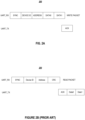
FIG. 2A shows a common format for a write packet and a corresponding acknowledgement packet. -
FIG. 2B shows a common format for a read packet and a corresponding acknowledgement packet. -
FIG. 3 shows an example of a conventional acknowledgement frame. -
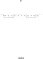
FIG. 4 illustrates an example of an error acknowledgment frame according to various embodiments of the present disclosure. -
FIG. 5 is a flowchart of an illustrative fault communication process for increasing throughput, in accordance with various embodiments of the present disclosure. - In the following description, for purposes of explanation, specific details are set forth in order to provide an understanding of the invention. It will be apparent, however, to one skilled in the art that the invention can be practiced without these details. Furthermore, one skilled in the art will recognize that embodiments of the present invention, described below, may be implemented in a variety of ways, such as a process, an apparatus, a system, a device, or a method on a tangible computer-readable medium.
- Components, or modules, shown in diagrams are illustrative of exemplary embodiments of the invention and are meant to avoid obscuring the invention. It shall also be understood that throughout this discussion that components may be described as separate functional units, which may comprise sub-units, but those skilled in the art will recognize that various components, or portions thereof, may be divided into separate components or may be integrated together, including integrated within a single system or component. It should be noted that functions or operations discussed herein may be implemented as components. Components may be implemented in software, hardware, or a combination thereof.
- Furthermore, connections between components or systems within the figures are not intended to be limited to direct connections. Rather, data between these components may be modified, re-formatted, or otherwise changed by intermediary components. Also, additional or fewer connections may be used. It shall also be noted that the terms "coupled," "connected," or "communicatively coupled" shall be understood to include direct connections, indirect connections through one or more intermediary devices, and wireless connections.
- Reference in the specification to "one embodiment," "preferred embodiment," "an embodiment," or "embodiments" means that a particular feature, structure, characteristic, or function described in connection with the embodiment is included in at least one embodiment of the invention and may be in more than one embodiment. Also, the appearances of the above-noted phrases in various places in the specification are not necessarily all referring to the same embodiment or embodiments.
- The use of certain terms in various places in the specification is for illustration and should not be construed as limiting. A service, function, or resource is not limited to a single service, function, or resource; usage of these terms may refer to a grouping of related services, functions, or resources, which may be distributed or aggregated.
- The terms "include," "including," "comprise," and "comprising" shall be understood to be open terms and any lists that follow are examples and not meant to be limited to the listed items. Any headings used herein are for organizational purposes only and shall not be used to limit the scope of the description or the claims. Each reference mentioned in this patent document is incorporate by reference herein in its entirety.
- Furthermore, it shall be noted that embodiments described herein are framed in the context of UART over CAN communication systems, but one skilled in the art shall recognize that the teachings of the present disclosure are not limited to such applications and may equally be used in other contexts.
- In this document the terms "acknowledgment," "acknowledgment frame," and "acknowledgment response" may be used interchangeably. Similarly, the terms "acknowledgement frame," "error acknowledgement frame," and "error acknowledgment response" may be used interchangeably. Further, the terms "microcontroller unit" and "microcontroller" are used interchangeably. The terms "normal" and "traditional" refer to conventional methods recognized by one of skilled in the art.
-
FIG. 1 illustrates an exemplary UART over CAN communication system according to various embodiments of the present disclosure.System 100 comprises three distinct boards 102-106, each comprising a CAN transceiver 112-116. In embodiments,board 102 may comprise a host device, which inFIG. 1 is implemented as a host MCU. Conversely,board 104 comprisesslave devices board 106 comprisesslave device 134. Slave devices 130-134 may perform any number of tasks depending on the received commands from host MCU 120. - As mentioned in the background, in traditional applications slave devices that are equipped with fault monitoring circuitry are implemented on the same board as the host MCU. Typical faults or errors that the fault monitoring circuitry may detect in lighting applications and communicate to the host MCU, include LEDs being electrically shorted across a terminal or to ground; an open circuit condition in the circuit, such as in a PCB trace of an LED; a temperature limit being exceeded; an incorrect address error; a communication error; and many others.
- The traditional approach, where the MCU individually communicates with each slave device, sends commands to constantly poll the fault registers of the slave devices, and receives from each slave device fault information, unnecessarily increases the bandwidth overhead and degrades the usable bandwidth available. For example, whenever a host MCU sends a valid command to any of the slave devices, e.g., in a write packet, as illustrated in
FIG. 2A , or in a read packet, as illustrated inFIG. 2B , the slave device will typically respond with a corresponding frame of data acknowledging that the slave device successfully received the command sent by the host MCU.FIG. 3 shows an example of a conventional acknowledgement frame that contains eight data bits between a start bit, a parity bit (OxC3), and a stop bit. To reduce the volume of communication between the MCU and the individual slave devices and increase available bandwidth, it would thus be desirable to have systems and methods that allow for reducing the total number of commands that the MCU must communicate to various devices during regular operation. - Returning to
FIG. 1 , various embodiments herein utilize host MCU 120 that may remotely control any number of slave devices (e.g., 130-134) without the need for local on-board MCUs or clocks. Advantageously, this allows a single MCU (e.g., 120) to control any number of boards, for example, to control various headlights rather than having to implement a dedicated MCU for each board, i.e., each headlight. Further, to help alleviate the need for actively polling slave devices 130-134 for faults by specifically communicating to fault registers (not shown inFIG. 1 ), various embodiments herein utilize a novel type of acknowledgment frame that may serve as an error acknowledgment frame. In embodiments, such error acknowledgment frames may comprise any number of bits, e.g., located between at least one start bit and one stop bit. An error acknowledgement frame may be unique and distinctly different from a traditional acknowledgement frame in that, in operation, in response to a successful command being sent fromhost MCU 120 to any of slave devices 130-134 and any number of faults being present in the circuit, instead of sending a traditional acknowledgement frame, a different frame may be sent. - It is noted that in addition to comprising, for example, generic error messages, an error acknowledgment response according to various embodiments herein may further comprise any number of unique responses representing any number or combination of faults that may have been detected by any of slave devices 130-134.
-
FIG. 4 illustrates an example of an error acknowledgment frame (Ox3C) according to various embodiments of the present disclosure. As depicted,error acknowledgment frame 400 is uniquely different from traditional acknowledgement frames, such as that shown inFIG. 3 . It is understood that, in embodiments, if no error is present,error acknowledgement frame 400 may mirror a traditional acknowledgement frame. In addition, in embodiments, if an error in UART communication is detected, neither a traditional acknowledgement frame nor an error acknowledgement frame is sent. - Advantageously,
error acknowledgment frame 400 may be used to constantly monitor slave devices for faults in circuit behavior without the MCU having to send additional commands to poll the slave devices' fault registers. - In embodiments, an individual slave device, in response to receiving a valid command, e.g., from an MCU, may respond with either a traditional acknowledgment or a novel error acknowledgement. Conversely, in cases where a slave device received an invalid command, the slave device may respond by returning no acknowledgement.
- Advantageously, a combination of these responses allows for the host MCU to achieve near real-time monitoring of any number of slave devices. For comparison, using conventional methods, assuming there exist 11 slave devices that are receiving commands, to periodically poll each device for its error status, four frames (sync, device ID, address, and CRC) must be sent to each device to request their status. In return, each device will respond with a normal acknowledgement frame, and two additional frames that contain data of the error register. As a result, there are 847 bits being sent and received in total ((11 bits per frame) * (4 command frames + 3 response frames) * (11 devices)). Further, assuming communication at 1 MBPS (one million bits per second), this means that 847 microseconds of additional time is used in looking at the error status registers. Further, this problem is exacerbated at lower communication rates. In contrast, the systems and methods herein reduce or completely eliminate this additional time, as this information would have been communicated during prior write commands.
-
FIG. 5 is a flowchart of an illustrative fault communication process for increasing throughput, in accordance with various embodiments of the present disclosure. In embodiments,process 500 may begin atstep 505 when a device, such as a board, receives a command from a host device. Atstep 510, it may be determined whether the received command is a valid command and, if so,process 500 may continue withstep 515 to determine whether the board compromises a fault, such as, e.g., a short condition. Otherwise, once it is determined that the received command is invalid,process 500 may move to step 530 to cause the board to not respond to the host with an acknowledgement and resume, atstep 505, with receiving a next comment from the host. In embodiments, if, atstep 515, it is determined that the board comprises no fault, the board may communicate an acknowledgement to the host and resume withstep 505 to receive the next comment from the host. - Conversely, if it is determined that the board does comprise a fault, the board may communicate, at
step 525, an error acknowledgement to the host before resuming to receive the next comment from the host, atstep 505. One skilled in the art shall recognize that: (1) certain steps may optionally be performed; (2) steps may not be limited to the specific order set forth herein; (3) certain steps may be performed in different orders; and (4) certain steps may be done concurrently. - Overall, the systems and methods herein implement a novel error acknowledgement frame that alerts a host device of faults to improve communication throughput and allow for near real-time monitoring of faults without the need to directly request fault information from each slave device.
- Aspects of the present invention may be encoded upon one or more non-transitory computer-readable media with instructions for one or more processors or processing units to cause steps to be performed. It shall be noted that the one or more non-transitory computer-readable media shall include volatile and non-volatile memory. It shall be noted that alternative implementations are possible, including a hardware implementation or a software/hardware implementation. Hardware-implemented functions may be realized using ASIC(s), programmable arrays, digital signal processing circuitry, or the like. Accordingly, the "means" terms in any claims are intended to cover both software and hardware implementations. Similarly, the term "computer-readable medium or media" as used herein includes software and/or hardware having a program of instructions embodied thereon, or a combination thereof. With these implementation alternatives in mind, it is to be understood that the figures and accompanying description provide the functional information one skilled in the art would require to write program code (i.e., software) and/or to fabricate circuits (i.e., hardware) to perform the processing required.
- It shall be noted that embodiments of the present invention may further relate to computer products with a non-transitory, tangible computer-readable medium that have computer code thereon for performing various computer-implemented operations. The media and computer code may be those specially designed and constructed for the purposes of the present invention, or they may be of the kind known or available to those having skill in the relevant arts. Examples of tangible computer-readable media include, but are not limited to: magnetic media such as hard disks, floppy disks, and magnetic tape; optical media such as CD-ROMs and holographic devices; magneto-optical media; and hardware devices that are specially configured to store or to store and execute program code, such as application specific integrated circuits (ASICs), programmable logic devices (PLDs), flash memory devices, and ROM and RAM devices. Examples of computer code include machine code, such as produced by a compiler, and files containing higher level code that are executed by a computer using an interpreter. Embodiments of the present invention may be implemented in whole or in part as machine-executable instructions that may be in program modules that are executed by a processing device. Examples of program modules include libraries, programs, routines, objects, components, and data structures. In distributed computing environments, program modules may be physically located in settings that are local, remote, or both.
- One skilled in the art will recognize no computing system or programming language is critical to the practice of the present invention. It will be appreciated to those skilled in the art that the preceding examples and embodiments are exemplary and not limiting to the scope of the present disclosure. It is intended that all permutations, enhancements, equivalents, combinations, and improvements thereto that are apparent to those skilled in the art upon a reading of the specification and a study of the drawings are included within the true spirit and scope of the present disclosure. It shall also be noted that elements of any claims may be arranged differently including having multiple dependencies, configurations, and combinations.
- There follows a list of numbered features representing particular embodiments of the present disclosure. Where a numbered feature refers to one or more earlier numbered features then those features should be considered in combination.
- 1. A fault communication method for increasing throughput, the method comprising:
- in response to receiving a valid command from a first device, performing steps comprising:
- in response to no fault condition being present in a circuit, communicating an acknowledgement response to the first device; and
- in response to determining that a fault condition is present, communicating an error acknowledgement response to the first device, the error acknowledgement response being different from the acknowledgement response; and
- in response to receiving from the first device an invalid command, communicating neither the acknowledgement response nor the error acknowledgement response to the first device.
- in response to receiving a valid command from a first device, performing steps comprising:
- 2. The method according to
feature 1, wherein the first device is a host device that controls one or more devices. - 3. The method according to
feature 2, further comprising, in response to determining that the fault condition is present in the circuit, storing a fault in a register of a second device among the one or more devices. - 4. The method according to
features - 5. The method according to any of the preceding features, further comprising, using a monitoring circuit to determine whether the fault condition is present in the circuit.
- 6. The method according to feature 5, wherein the first device does not send a command to poll the monitoring circuit to determine whether the fault condition is present.
- 7. The method according to any of the preceding features, wherein the valid command comprises a command to control one or more lighting functions in an automotive lighting application.
- 8. The method according to any of the preceding features, wherein the error acknowledgement response is communicated within an acknowledgement frame that comprises a number of bits located between at least one start bit and one stop bit.
- 9. A fault detection circuit comprising:
- a monitoring circuit coupled to a circuit, the monitoring circuit determines whether a fault condition is present in the circuit; and
- a fault register coupled to the monitoring circuit, the fault detection circuit, in response to receiving a valid command from a host device, performs steps comprising:
- in response to no fault condition being present in the circuit, communicating an acknowledgement response to the host device; and
- in response to determining that the fault condition is present, communicating an error acknowledgement response to the host device, the error acknowledgement response being different from the acknowledgement response; and
- in response to receiving an invalid command from the host device, not communicating the acknowledgement response or the error acknowledgement response to the host device to reduce unnecessary communication.
- 10. The fault detection circuit according to feature 9, wherein the fault register is not periodically polled to determine whether the fault condition is present.
- 11. The fault detection circuit according to features 9 or 10, wherein the invalid command represents a communication error in a Universal Asynchronous Receiver-Transmitter (UART) communication.
- 12. The fault detection circuit according to any of features 9 to 11, wherein the error acknowledgement response comprises an acknowledgement frame that comprises a number of bits located between at least one start bit and one stop bit.
- 13. The fault detection circuit according to any of features 9 to 12, wherein the error acknowledgement response comprises information identifying a specific fault condition detected by the monitoring circuit.
- 14. The fault detection circuit according to any of features 9 to 13, wherein the valid command comprises a command to control one or more lighting functions in an automotive lighting application.
- 15. A fault detection system comprising:
- a circuit;
- a host device coupled to the circuit;
- a fault detection circuit coupled to the host device, the fault detection circuit comprising:
- a fault register; and
- a monitoring circuit that determines whether a fault condition is present in the circuit, the fault detection circuit, in response to receiving a valid command from the host device, performs steps comprising:
- in response to no fault condition being present in the circuit, communicating an acknowledgement response to the host device;
- in response to determining that the fault condition is present, communicating an error acknowledgement response to the host device, the error acknowledgement response being different from the acknowledgement response; and
- in response to receiving an invalid command from the host device, not communicating the acknowledgement response or the error acknowledgement response to the host device.
- 16. The fault detection system according to feature 15, wherein the fault register is not periodically polled to determine whether the fault condition is present.
- 17. The fault detection system according to features 15 or 16, wherein the host device controls one or more devices.
- 18. The fault detection system according to any of features 15 to 17, wherein the invalid command represents a communication error in a Universal Asynchronous Receiver-Transmitter (UART) communication.
- 19. The fault detection system according to any of features 15 to 18, wherein the error acknowledgement response comprises information identifying a specific fault condition detected by the monitoring circuit.
- 20. The fault detection system according to any of features 15 to 19, wherein the valid command comprises a command to control one or more lighting functions in an automotive lighting application.
Claims (15)
- A fault communication method for increasing throughput, the method comprising:in response to receiving a valid command from a first device, performing steps comprising:in response to no fault condition being present in a circuit, communicating an acknowledgement response to the first device; andin response to determining that a fault condition is present, communicating an error acknowledgement response to the first device, the error acknowledgement response being different from the acknowledgement response; andin response to receiving from the first device an invalid command, communicating neither the acknowledgement response nor the error acknowledgement response to the first device.
- The method according to claim 1, wherein the first device is a host device that controls one or more devices.
- The method according to claim 2, further comprising, in response to determining that the fault condition is present in the circuit, storing a fault in a register of a second device among the one or more devices.
- The method according to claims 2 or 3, wherein the invalid command represents a communication error in a Universal Asynchronous Receiver-Transmitter (UART) communication between the first device and at least one of the one or more devices.
- The method according to any of the preceding claims, further comprising, using a monitoring circuit to determine whether the fault condition is present in the circuit.
- The method according to claim 5, wherein the first device does not send a command to poll the monitoring circuit to determine whether the fault condition is present.
- The method according to any of the preceding claims, wherein the valid command comprises a command to control one or more lighting functions in an automotive lighting application.
- The method according to any of the preceding claims, wherein the error acknowledgement response is communicated within an acknowledgement frame that comprises a number of bits located between at least one start bit and one stop bit.
- A fault detection circuit comprising:a monitoring circuit coupled to a circuit, the monitoring circuit determines whether a fault condition is present in the circuit; anda fault register coupled to the monitoring circuit, the fault detection circuit, in response to receiving a valid command from a host device, performs steps comprising:in response to no fault condition being present in the circuit, communicating an acknowledgement response to the host device; andin response to determining that the fault condition is present, communicating an error acknowledgement response to the host device, the error acknowledgement response being different from the acknowledgement response; andin response to receiving an invalid command from the host device, not communicating the acknowledgement response or the error acknowledgement response to the host device to reduce unnecessary communication.
- The fault detection circuit according to claim 9, wherein the fault register is not periodically polled to determine whether the fault condition is present.
- The fault detection circuit according to claims 9 or 10, wherein the invalid command represents a communication error in a Universal Asynchronous Receiver-Transmitter (UART) communication.
- The fault detection circuit according to any of claims 9 to 11, wherein the error acknowledgement response comprises an acknowledgement frame that comprises a number of bits located between at least one start bit and one stop bit.
- The fault detection circuit according to any of claims 9 to 12, wherein the error acknowledgement response comprises information identifying a specific fault condition detected by the monitoring circuit.
- The fault detection circuit according to any of claims 9 to 13, wherein the valid command comprises a command to control one or more lighting functions in an automotive lighting application.
- A fault detection system comprising:a circuit;a host device coupled to the circuit; anda fault detection circuit coupled to the host device, the fault detection circuit being a fault detection circuit according to any of claims 9 to 14.
Applications Claiming Priority (2)
| Application Number | Priority Date | Filing Date | Title |
|---|---|---|---|
| US202263435206P | 2022-12-23 | 2022-12-23 | |
| US18/520,710 US12613517B2 (en) | 2022-12-23 | 2023-11-28 | Fault monitoring systems and methods |
Publications (2)
| Publication Number | Publication Date |
|---|---|
| EP4390710A1 true EP4390710A1 (en) | 2024-06-26 |
| EP4390710B1 EP4390710B1 (en) | 2026-03-11 |
Family
ID=89224244
Family Applications (1)
| Application Number | Title | Priority Date | Filing Date |
|---|---|---|---|
| EP23218130.5A Active EP4390710B1 (en) | 2022-12-23 | 2023-12-19 | Fault monitoring systems and methods |
Country Status (2)
| Country | Link |
|---|---|
| US (1) | US12613517B2 (en) |
| EP (1) | EP4390710B1 (en) |
Families Citing this family (1)
| Publication number | Priority date | Publication date | Assignee | Title |
|---|---|---|---|---|
| US12511187B1 (en) * | 2025-02-28 | 2025-12-30 | Citibank, N.A. | Monitoring emerging faults |
Citations (2)
| Publication number | Priority date | Publication date | Assignee | Title |
|---|---|---|---|---|
| WO2007079085A2 (en) * | 2005-12-29 | 2007-07-12 | Interdigital Technology Corporation | Method and system for implementing h-arq-assisted arq operation |
| US20210302488A1 (en) * | 2020-03-29 | 2021-09-30 | Maxim Integrated Products, Inc. | Systems and methods for fault detection and reporting through serial interface transceivers |
Family Cites Families (2)
| Publication number | Priority date | Publication date | Assignee | Title |
|---|---|---|---|---|
| US8549198B2 (en) * | 2009-03-27 | 2013-10-01 | Schneider Electric It Corporation | Communication protocol |
| US20250078583A1 (en) * | 2023-08-31 | 2025-03-06 | Robert Bosch Gmbh | Cloud-Based Vehicle Diagnostic System Having Specialized Data |
-
2023
- 2023-11-28 US US18/520,710 patent/US12613517B2/en active Active
- 2023-12-19 EP EP23218130.5A patent/EP4390710B1/en active Active
Patent Citations (2)
| Publication number | Priority date | Publication date | Assignee | Title |
|---|---|---|---|---|
| WO2007079085A2 (en) * | 2005-12-29 | 2007-07-12 | Interdigital Technology Corporation | Method and system for implementing h-arq-assisted arq operation |
| US20210302488A1 (en) * | 2020-03-29 | 2021-09-30 | Maxim Integrated Products, Inc. | Systems and methods for fault detection and reporting through serial interface transceivers |
Non-Patent Citations (1)
| Title |
|---|
| WILBUR PLACE: "MIL-STD-1553 DESIGNER'S GUIDE", 8 December 2003 (2003-12-08), XP055462493, Retrieved from the Internet <URL:http://www.ddc-web.com/Documents/dguidehg.pdf> [retrieved on 20180323] * |
Also Published As
| Publication number | Publication date |
|---|---|
| US20240210931A1 (en) | 2024-06-27 |
| US12613517B2 (en) | 2026-04-28 |
| EP4390710B1 (en) | 2026-03-11 |
Similar Documents
| Publication | Publication Date | Title |
|---|---|---|
| JP4077812B2 (en) | Integrated circuit routers that support individual transmission rates | |
| TWI730993B (en) | First communication device, communication method, and communication system | |
| US7010639B2 (en) | Inter integrated circuit bus router for preventing communication to an unauthorized port | |
| US20150019918A1 (en) | Method and Apparatus for Reducing Read Latency | |
| EP1650670B1 (en) | Serial bus system | |
| US7082488B2 (en) | System and method for presence detect and reset of a device coupled to an inter-integrated circuit router | |
| CN104782082B (en) | For the new method of Controller Area Network BUS processing | |
| US7630304B2 (en) | Method of overflow recovery of I2C packets on an I2C router | |
| US8185680B2 (en) | Method for changing ownership of a bus between master/slave devices | |
| EP2985955B1 (en) | Controller area network (can) device and method for emulating classic can error management | |
| US10721022B2 (en) | Communication apparatus, communication method, program, and communication system | |
| TWI408931B (en) | Data communication device, communication control method, and program | |
| EP4390710A1 (en) | Fault monitoring systems and methods | |
| JP4511358B2 (en) | How to transmit data on the bus | |
| CN110177034B (en) | Subscriber station for a bus system and method for increasing the data rate of a bus system | |
| US20040255070A1 (en) | Inter-integrated circuit router for supporting independent transmission rates | |
| US10805043B2 (en) | Data transmission apparatus and data transmission method, reception device and reception method, program, and data transmission system | |
| US20040255071A1 (en) | Inter-integrated circuit bus router for providing increased security | |
| US8488621B2 (en) | Communication network system and error verification method | |
| JP5407230B2 (en) | PCI card, motherboard, PCI bus system, control method, and program | |
| CN100365994C (en) | Method and system for regulating ethernet | |
| CN115664599B (en) | A data transmission method, device, electronic equipment and storage medium | |
| CN112291128B (en) | Bus-based communication system, system on chip and method therefor | |
| JP2005006306A (en) | Inter-integrated circuit router error management system and method | |
| CN118250193A (en) | Fault detection system and method |
Legal Events
| Date | Code | Title | Description |
|---|---|---|---|
| PUAI | Public reference made under article 153(3) epc to a published international application that has entered the european phase |
Free format text: ORIGINAL CODE: 0009012 |
|
| STAA | Information on the status of an ep patent application or granted ep patent |
Free format text: STATUS: REQUEST FOR EXAMINATION WAS MADE |
|
| 17P | Request for examination filed |
Effective date: 20231219 |
|
| AK | Designated contracting states |
Kind code of ref document: A1 Designated state(s): AL AT BE BG CH CY CZ DE DK EE ES FI FR GB GR HR HU IE IS IT LI LT LU LV MC ME MK MT NL NO PL PT RO RS SE SI SK SM TR |
|
| STAA | Information on the status of an ep patent application or granted ep patent |
Free format text: STATUS: EXAMINATION IS IN PROGRESS |
|
| 17Q | First examination report despatched |
Effective date: 20250310 |
|
| GRAP | Despatch of communication of intention to grant a patent |
Free format text: ORIGINAL CODE: EPIDOSNIGR1 |
|
| STAA | Information on the status of an ep patent application or granted ep patent |
Free format text: STATUS: GRANT OF PATENT IS INTENDED |
|
| RIC1 | Information provided on ipc code assigned before grant |
Ipc: G06F 13/42 20060101AFI20251031BHEP Ipc: G06F 11/30 20060101ALI20251031BHEP Ipc: G01R 31/28 20060101ALI20251031BHEP Ipc: H04L 43/0817 20220101ALI20251031BHEP Ipc: G06F 11/07 20060101ALI20251031BHEP Ipc: H04L 1/1829 20230101ALI20251031BHEP Ipc: H04L 1/1607 20230101ALI20251031BHEP Ipc: H04L 41/0686 20220101ALI20251031BHEP Ipc: H04L 12/40 20060101ALI20251031BHEP Ipc: G06F 13/40 20060101ALI20251031BHEP Ipc: G06F 13/38 20060101ALI20251031BHEP Ipc: G06F 13/12 20060101ALI20251031BHEP Ipc: G01R 31/00 20060101ALI20251031BHEP |
|
| INTG | Intention to grant announced |
Effective date: 20251113 |
|
| GRAS | Grant fee paid |
Free format text: ORIGINAL CODE: EPIDOSNIGR3 |
|
| GRAA | (expected) grant |
Free format text: ORIGINAL CODE: 0009210 |
|
| STAA | Information on the status of an ep patent application or granted ep patent |
Free format text: STATUS: THE PATENT HAS BEEN GRANTED |
|
| AK | Designated contracting states |
Kind code of ref document: B1 Designated state(s): AL AT BE BG CH CY CZ DE DK EE ES FI FR GB GR HR HU IE IS IT LI LT LU LV MC ME MK MT NL NO PL PT RO RS SE SI SK SM TR |
|
| REG | Reference to a national code |
Ref country code: CH Ref legal event code: F10 Free format text: ST27 STATUS EVENT CODE: U-0-0-F10-F00 (AS PROVIDED BY THE NATIONAL OFFICE) Effective date: 20260311 Ref country code: GB Ref legal event code: FG4D |
|
| REG | Reference to a national code |
Ref country code: DE Ref legal event code: R096 Ref document number: 602023013316 Country of ref document: DE |
|
| REG | Reference to a national code |
Ref country code: IE Ref legal event code: FG4D |