EP4390632A1 - Electronic device - Google Patents
Electronic device Download PDFInfo
- Publication number
- EP4390632A1 EP4390632A1 EP22858152.6A EP22858152A EP4390632A1 EP 4390632 A1 EP4390632 A1 EP 4390632A1 EP 22858152 A EP22858152 A EP 22858152A EP 4390632 A1 EP4390632 A1 EP 4390632A1
- Authority
- EP
- European Patent Office
- Prior art keywords
- housing
- electronic device
- end side
- key
- display
- Prior art date
- Legal status (The legal status is an assumption and is not a legal conclusion. Google has not performed a legal analysis and makes no representation as to the accuracy of the status listed.)
- Pending
Links
Images


Classifications
-
- H—ELECTRICITY
- H05—ELECTRIC TECHNIQUES NOT OTHERWISE PROVIDED FOR
- H05K—PRINTED CIRCUITS; CASINGS OR CONSTRUCTIONAL DETAILS OF ELECTRIC APPARATUS; MANUFACTURE OF ASSEMBLAGES OF ELECTRICAL COMPONENTS
- H05K5/00—Casings, cabinets or drawers for electric apparatus
- H05K5/0017—Casings, cabinets or drawers for electric apparatus with operator interface units
- H05K5/0018—Casings, cabinets or drawers for electric apparatus with operator interface units having an electronic display
-
- H—ELECTRICITY
- H01—ELECTRIC ELEMENTS
- H01H—ELECTRIC SWITCHES; RELAYS; SELECTORS; EMERGENCY PROTECTIVE DEVICES
- H01H13/00—Switches having rectilinearly-movable operating part or parts adapted for pushing or pulling in one direction only, e.g. push-button switch
- H01H13/70—Switches having rectilinearly-movable operating part or parts adapted for pushing or pulling in one direction only, e.g. push-button switch having a plurality of operating members associated with different sets of contacts, e.g. keyboard
- H01H13/702—Switches having rectilinearly-movable operating part or parts adapted for pushing or pulling in one direction only, e.g. push-button switch having a plurality of operating members associated with different sets of contacts, e.g. keyboard with contacts carried by or formed from layers in a multilayer structure, e.g. membrane switches
- H01H13/705—Switches having rectilinearly-movable operating part or parts adapted for pushing or pulling in one direction only, e.g. push-button switch having a plurality of operating members associated with different sets of contacts, e.g. keyboard with contacts carried by or formed from layers in a multilayer structure, e.g. membrane switches characterised by construction, mounting or arrangement of operating parts, e.g. push-buttons or keys
-
- G—PHYSICS
- G06—COMPUTING OR CALCULATING; COUNTING
- G06F—ELECTRIC DIGITAL DATA PROCESSING
- G06F15/00—Digital computers in general; Data processing equipment in general
- G06F15/02—Digital computers in general; Data processing equipment in general manually operated with input through keyboard and computation using a built-in program, e.g. pocket calculators
- G06F15/0216—Constructional details or arrangements
-
- G—PHYSICS
- G06—COMPUTING OR CALCULATING; COUNTING
- G06F—ELECTRIC DIGITAL DATA PROCESSING
- G06F3/00—Input arrangements for transferring data to be processed into a form capable of being handled by the computer; Output arrangements for transferring data from processing unit to output unit, e.g. interface arrangements
- G06F3/01—Input arrangements or combined input and output arrangements for interaction between user and computer
- G06F3/02—Input arrangements using manually operated switches, e.g. using keyboards or dials
-
- G—PHYSICS
- G06—COMPUTING OR CALCULATING; COUNTING
- G06F—ELECTRIC DIGITAL DATA PROCESSING
- G06F3/00—Input arrangements for transferring data to be processed into a form capable of being handled by the computer; Output arrangements for transferring data from processing unit to output unit, e.g. interface arrangements
- G06F3/01—Input arrangements or combined input and output arrangements for interaction between user and computer
- G06F3/02—Input arrangements using manually operated switches, e.g. using keyboards or dials
- G06F3/0202—Constructional details or processes of manufacture of the input device
-
- G—PHYSICS
- G06—COMPUTING OR CALCULATING; COUNTING
- G06F—ELECTRIC DIGITAL DATA PROCESSING
- G06F3/00—Input arrangements for transferring data to be processed into a form capable of being handled by the computer; Output arrangements for transferring data from processing unit to output unit, e.g. interface arrangements
- G06F3/01—Input arrangements or combined input and output arrangements for interaction between user and computer
- G06F3/02—Input arrangements using manually operated switches, e.g. using keyboards or dials
- G06F3/0202—Constructional details or processes of manufacture of the input device
- G06F3/0216—Arrangements for ergonomically adjusting the disposition of keys of a keyboard
-
- G—PHYSICS
- G06—COMPUTING OR CALCULATING; COUNTING
- G06F—ELECTRIC DIGITAL DATA PROCESSING
- G06F3/00—Input arrangements for transferring data to be processed into a form capable of being handled by the computer; Output arrangements for transferring data from processing unit to output unit, e.g. interface arrangements
- G06F3/01—Input arrangements or combined input and output arrangements for interaction between user and computer
- G06F3/03—Arrangements for converting the position or the displacement of a member into a coded form
- G06F3/033—Pointing devices displaced or positioned by the user, e.g. mice, trackballs, pens or joysticks; Accessories therefor
- G06F3/0354—Pointing devices displaced or positioned by the user, e.g. mice, trackballs, pens or joysticks; Accessories therefor with detection of two-dimensional [2D] relative movements between the device, or an operating part thereof, and a plane or surface, e.g. 2D mice, trackballs, pens or pucks
- G06F3/03547—Touch pads, in which fingers can move on a surface
-
- H—ELECTRICITY
- H01—ELECTRIC ELEMENTS
- H01H—ELECTRIC SWITCHES; RELAYS; SELECTORS; EMERGENCY PROTECTIVE DEVICES
- H01H13/00—Switches having rectilinearly-movable operating part or parts adapted for pushing or pulling in one direction only, e.g. push-button switch
- H01H13/70—Switches having rectilinearly-movable operating part or parts adapted for pushing or pulling in one direction only, e.g. push-button switch having a plurality of operating members associated with different sets of contacts, e.g. keyboard
-
- H—ELECTRICITY
- H05—ELECTRIC TECHNIQUES NOT OTHERWISE PROVIDED FOR
- H05K—PRINTED CIRCUITS; CASINGS OR CONSTRUCTIONAL DETAILS OF ELECTRIC APPARATUS; MANUFACTURE OF ASSEMBLAGES OF ELECTRICAL COMPONENTS
- H05K5/00—Casings, cabinets or drawers for electric apparatus
- H05K5/02—Details
- H05K5/0217—Mechanical details of casings
Definitions
- the present invention relates to an electronic device with a display and a keyboard.
- an electronic device called a calculator is provided with a display and a key input section on the top of its housing.
- the key input section has multiple keys arranged in a matrix pattern.
- the key input section has numeric keys, arithmetic keys, function keys, etc., each including multiple keys.
- the electronic device is desired to be capable of enabling accurate and quick hitting of keys of the key input section, without easily causing fatigue even from use for a long time.
- the angle of inclination of the keyboard operation surface can be desirably changed by differentiating its front and back heights with respect to the operator.
- Patent Document 1 According to the conventional art as disclosed in Patent Document 1, therefore, the degree of fatigue can be mitigated by providing a configuration in which the angle of inclination of the keyboard operation surface is variable in the front-and-back direction with respect to the operator. Nevertheless, what is considered in this patent application publication is the operability with a keyboard device alone, and it does not assume the viewability of a display for combined use. Even more, Document 1 does not assume one-hand key operation and is silent as to mitigation in the degree of fatigue for cases where keys are operated with one hand.
- the present invention has been formulated in view of such problems and its objects include providing an electronic device capable of realizing good key operability while securing a display viewability, so that the user is not easily fatigued.
- an electronic device includes: a display section including a display surface extending from a first-end side of a housing to a second-end side of the housing opposite the first-end side; and a plurality of operation parts arranged from the first-end side to the second-end side of the housing and each including an operation surface. At least a portion of the operation surface of a first operation part, which is arranged on the first-end side, has a height from a placement surface greater than that of at least a portion of the operation surface of a second operation part, which is arranged on the second-end side.
- the display surface of the display section has a height from the placement surface which is not greater on the first-end side than on the second-end side.
- an electronic device capable of realizing good key operability while securing a display viewability, so that the user is not easily fatigued.
- FIGS. 1, 2 , 3, and 4 are diagrams showing an external configuration of an electronic device 10 according to an embodiment.
- FIG. 1 is a plan view of the electronic device 10 according to the embodiment.
- FIG. 2 is a diagram of the electronic device 10 according to the embodiment, viewed from the lower-side-surface side.
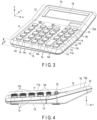
- FIG. 3 is a perspective view of the electronic device 10 according to the embodiment.
- FIG. 4 is a diagram of the electronic device 10 according to the embodiment, viewed from the right-side-surface side.
- the electronic device 10 is provided with a key input section 11 and a display section 12 on the top surface of its housing.
- the key input section 11 has multiple keys 14, one or more selector switches 15, and so on.
- the multiple keys 14 include, for example, numeric keys, arithmetic keys, function keys, etc.
- the numeric keys include, for example, multiple keys corresponding to [00] and [0] to [9], respectively.
- the function keys include, for example, an all-clear key (an [AC] key), a clear key (a [C] key), multiple memory keys ([MRC], [M-], and [M+] keys), a root key (a [V] key), and a [%] key.
- the selector switch or switches 15 include, for example, a round selector and a decimal point selector.
- the housing top surface of the electronic device 10 is formed in a substantially rectangular outer shape.
- the housing top surface includes the display section 12 on an upper side (the upper-edge side of the housing top surface) and the key input section 11 on a lower side (the lower-edge side of the housing top surface).
- a display 16 is disposed on a first housing surface 12a which is a first region (the upper side) of the housing top surface.
- the display 16 has, for example, a horizontally long rectangular display surface and extends from a first-end side (the left-edge side in FIG. 1 ) of the housing to a second-end side (the right-edge side in FIG. 1 ) opposite the first-end side.
- multiple keys 14 are arranged from the first-end side to the second-end side of the housing and on a second housing surface 11a which is a second region (the lower side) of the housing top surface.
- the multiple keys 14 each have an operation surface 14t on their respective key tops.
- the multiple keys 14, in one example, are arranged at predetermined intervals (key pitches) in each of the row and column directions, with the row direction assumed to be a direction parallel to the upper edge/the lower edge of the housing top surface and the column direction assumed to be a direction parallel to the left edge/the right edge of the housing top surface.
- the second housing surface 11a for the key input section 11 is inclined in a direction from the first-end side to the second-end side, i.e., in the row direction of the arrangement of the multiple keys 14, at a first inclination angle (angle ⁇ ) with respect to the placement surface (the bottom surface of the housing).
- the first housing surface 12a for the display section 12 is substantially in parallel (or substantially horizontal) to the placement surface (the bottom surface of the housing), or is inclined in the direction from the first-end side to the second-end side, i.e., in the row direction of the arrangement of the multiple keys 14, at a second inclination angle different from the first inclination angle (angle ⁇ ) with respect to the bottom surface of the housing.
- the second housing surface 11a of the electronic device 10 is formed to be inclined in the row direction, in which the keys 14 are arranged, at the angle ⁇ with respect to the bottom surface 13 of the housing.
- the angle ⁇ be in a range of 1° to 9°. It is further preferred that the angle ⁇ be in a range of, for example, 1° to 3° (this will be described in more detail later, referring to FIG. 6 ).
- FIGS. 1 to 4 illustrate a configuration of the electronic device 10 which is an example where the second housing surface 11a of the key input section 11 has a rightward inclination (the left-edge side is higher than the right-edge side) as depicted in FIGS. 2 and 4 .
- the operation surface 14t of the key 14 (a first operation part) on the first-end side (the left-edge side) is formed to have a greater height from the placement surface (the bottom surface of the housing) than that of at least a portion of the operation surface 14t of the key 14 (a second operation part) on the second-end side (the right-edge side).
- the central portion (a first central portion) of the operation surface 14t of the key 14 arranged on the first-end side has a greater height from the placement surface (the bottom surface of the housing) than that of the central portion (a second central portion) of the operation surface 14t of the key 14 arranged on the second-end side.
- the second housing surface 11a of the key input section 11 has a leftward inclination.
- at least a portion of the operation surface 14t of the key 14 on the second-end side is formed to have a greater height from the placement surface (the bottom surface of the housing) than that of at least a portion of the operation surface 14t of the key 14 on the second-end side (the left-edge side).
- the display surface of the display section 12 is formed such that its portion on the first-end side has a height from the placement surface (the bottom surface of the housing) not greater than that of its portion on the second-end side.
- the first-end portion (the left-edge portion) and the second-end portion (the right-edge portion) of the display section 12 are aligned at the same height, and the upper-edge side of the housing top surface is raised from the boundary between the key input section 11 and the display section 12, so that the inclination in the column direction (the front-and-back direction) of the arrangement of the multiple keys 14 is formed.
- the housing of the electronic device 10 is bent at the boundary between the key input section 11 and the display section 12 so that the upper-edge side of the housing top surface is positioned higher. Accordingly, the first housing surface 12a for the display section 12 is inclined in the column direction in which the multiple keys 14 are arranged, thereby enhancing viewability of the display surface of the display 16.
- FIG. 5 is a diagram showing an exemplary cross-section taken along the line A-A shown in FIG. 1 .
- a substrate 22 is provided in a state parallel to the second housing surface 11a of the key input section 11.
- the substrate 22 is supported by multiple support members 24 formed from the bottom portion 13.
- the substrate 22 supports, inside the housing, the multiple keys 14.
- the keys 14 are constituted by, for example, a rubber key 21a and key tops 14a1, 14a2, and 14a3.
- the rubber key 21a is placed on the upper surface of the substrate 22.
- the rubber key 21a includes rubber key tops 21a1, 21a2, and 21a3 formed at positions corresponding to the respective key tops 14a1, 14a2, and 14a3 of the multiple keys 14.
- To the rubber key tops 21a1, 21a2, and 21a3, the respectively corresponding key tops 14a1, 14a2, and 14a3 are attached so that their key stroke directions are made perpendicular to the second housing surface 11a.
- the second housing surface 11a has openings corresponding to the multiple keys 14.
- the openings are each formed in such a manner that the opening wall surface is substantially perpendicular to the substrate 22 and that the opening wall surface and the second housing surface 11a form a substantially right angle.
- the key tops 14a1, 14a2, and 14a3 pass through the corresponding openings, and their respective operation surfaces 14ta1, 14ta2, and 14ta3 are supported at levels higher than the second housing surface 11a.
- the side surfaces of the key tops 14a1, 14a2, and 14a3 each face the opening wall surface of the corresponding opening with a slight clearance therebetween so that a substantially parallel movement is permitted.
- the rubber key tops 21a1, 21a2, and 21a3 are supported so that they are normally separated from the substrate 24 but are pressed downward until they contact the substrate 24 at the time of a depressing action, in order to provide a feel of a click in response to a depressing action on the key tops 14a1, 14a2, and 14a3 attached on the respective rubber key tops 21a1, 21a2, and 21a3.
- the rubber key tops 21a1, 21a2, and 21a3 are each provided with a conductive member at their bottom portions so that the rubber key tops 21a1, 21a2, and 21a3 pressed downward by the depressing action on the key tops 14a1, 14a2, and 14a3 will cause the conductive members to contact electrodes arranged on the substrate 22 for the detection of key depression events.
- the operation surfaces 14ta1, 14ta2, and 14ta3 (upper surfaces) of the key tops 14a1, 14a2, and 14a3 are each formed to be in parallel to the bottom surface 13.
- the operation surfaces 14ta1, 14ta2, and 14ta3 of the key tops 14a1, 14a2, and 14a3 are horizontal. Heights L1, L2, and L3 of the respective key tops 14a1, 14a2, and 14a3 decrease in order from the key top 14a1 on the first-end side to the key top 14a2 and the key top 14a3 in the direction of the second-end side.
- the key tops 14a1, 14a2, and 14a3 are formed in an analogous shape with a comparable stroke length defined by the movable ranges of the rubber key tops 21a1, 21a2, and 21a3, and therefore, the heights L1, L2, and L3 from the bottom surface 13 show a stepped profile according to the inclination angle ⁇ of the second housing surface 11a as shown in FIGS. 2 and 3 .
- the second housing surface 11a of the key input section 11 is inclined in the row direction of the keys 14 at the angle ⁇ with respect to the bottom surface 13, and the operation surface 14t of the key 14 disposed on the first-end side is higher than the operation surface 14t of the key 14 disposed on the second-end side. This realizes good operability with the keys 14 and prevents the user from being easily fatigued.
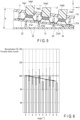
- FIG. 6 is a diagram showing a result of measuring an amount of muscle activity of users, with the second housing surface 11a of the key input section 11 inclined in the row direction of the key arrangement.
- a pronator teres muscle was targeted and what is shown is a result of collecting values measured by an electromyograph during key operations with the electromyograph attached to a position of the pronator teres muscle of an arm.
- FIG. 6 shows an average of measured values from multiple subjects for each angle. Also, in order to indicate a relationship between the measured values (the amounts of muscle activity) at the respective angles, FIG. 6 assumes that the measured value at the angle ⁇ being 0° is 100% and normalizes the measured values at the other angles 1° to 9°.
- orientations of the palms of the subjects during the key operations were measured. As a result, it was confirmed that in almost all the subjects, the palm was inclined to the right with respect to the horizontal plane (in the case where the keys were operated with the right hand). More concretely, the palms were tilted to the right at an angle ranging from about 5° to 13°.
- the palm of the hand and the second housing surface 11a during the user's key operation can face each other without a large difference in inclination, and accordingly, the operability with the keys 14 can be improved.
- an increase in the angle ⁇ may cause a sense of discomfort in users who are accustomed to key operations with an existing electronic device (calculator) in which multiple keys are not inclined to the right.
- the key input section 11 is inclined to the right, and together, the key top upper surfaces of the keys 14 are each formed horizontally. Therefore, for users who are accustomed to key operations with an existing electronic device (calculator) in which key top upper surfaces are formed horizontally, key operations can be performed without a sense of discomfort.
- FIG. 5 shows a configuration in which the upper surfaces of the key tops 14a1, 14a2, and 14a3 are formed horizontally (in parallel to the bottom surface 13), these key top upper surfaces may be formed into other shapes.
- FIG. 7 is a diagram showing an exemplary cross-section taken along the line A-A shown in FIG. 1 in the case where the shapes of the key top upper surfaces are changed.
- FIG. 7 assumes the same configuration as that shown in FIG. 5 except the operation parts, and thus, a detailed description of the overlapping configuration will be omitted.
- the key tops 14b1, 14b2, and 14b3 are attached to the respectively corresponding rubber key tops 21b1, 21b2, and 21b3 of the rubber key 21b formed in a similar manner to the rubber key 21a shown in FIG. 5 , so that their key stroke directions are made perpendicular to the second housing surface 11a.
- the operation surfaces 14tb1, 14tb2, and 14tb3 (upper surfaces) of the key tops 14b1, 14b2, and 14b3 are each formed to be in parallel to the second housing surface 11a of the key input section 11.
- the second housing surface 11a of the key input section 11 and the upper surfaces of all the key tops 14b1, 14b2, and 14b3 are in parallel to each other, and all the key tops 14b1, 14b2, and 14b3 have the same height L from the second housing surface 11a.
- the electronic device 10 used with the right hand for key operations is placed on the right hand side for use, rather than in front of the user.
- the second housing surface 11a of the key input section 11 is inclined to the right to improve the operability, etc.
- the first housing surface 12a of the display section 12 is inclined in the column direction of the key arrangement to secure the viewability of the display 16 instead of being inclined to the right in conformity with the second housing surface 11a.
- the electronic device 10 can realize good operability with the keys 14 and secure viewability of the display 16, so that the user is not easily fatigued.
- FIGS. 1 to 4 have assumed configurations for improving the viewability of the display surface of the display 16 by inclining the first housing surface 12a of the display section 12 in such a manner that the upper-edge side of the housing top surface is raised, it is also possible to adopt a configuration in which the first housing surface 12a has another inclining state as shown in FIG. 8 or FIG. 9 .
- FIG. 8 is a diagram of the electronic device 10 according to the embodiment with a modified first housing surface 12a of the display section 12, viewed from the right-side-surface side.
- the display section 12 is formed such that the upper-edge side of the housing top surface is raised from the boundary between the key input section 11 and the display section 12 so as to incline the display surface of the display 16.
- the display surface of the display 16 is formed to be substantially horizontal (substantially in parallel to the bottom surface of the housing).
- the left edge/the right edge of the housing top surface for the key input section 11 is formed to be in parallel to the first housing surface 12a of the display section 12.
- the display surface of the display 16 provided in the display section 12 is formed so as to be substantially horizontal (substantially in parallel to the bottom surface of the housing), thereby improving the viewability of the electronic device 10 from above.
- the viewability of the display 16 from above the electronic device 10 can be improved while the operability is also improved by the rightward inclination of the second housing surface 11a of the key input section 11.
- FIG. 9 is a diagram of the electronic device 10 according to the embodiment with a modified first housing surface 12a of the display section 12, viewed from the right-side-surface side.
- the first housing surface 12a of the display section 12 is inclined in the direction opposite the direction in which the second housing surface 11a of the key input section 11 is inclined.
- the second housing surface 11a of the key input section 11 is inclined to the right in the row direction of the multiple keys 14, and the first housing surface 12a of the display section 12 is inclined to the left in the row direction of the multiple keys 14.
- the electronic device 10 adopts the configuration in which, while the second housing surface 11a of the key input section 11 is inclined to the right to improve the operability, the first housing surface 12a of the display section 12 is inclined to the left contrary to the inclination of the second housing surface 11a. This realizes an even more enhanced viewability of the display 16 than in the configuration of only inclining the first housing surface 12a in the column direction (the front-and-back direction) of the arrangement of keys 14 as shown in FIG. 2 .
- the viewability of the display 16 may be enhanced by not only inclining the first housing surface 12a of the display section 12 to the left but also forming the first housing surface 12a such that its portion on the upper-edge side of the housing top surface is at a higher level.
- the electronic device 10 can realize good operability with the keys 14 while securing viewability of the display 16, so that it is possible to prevent the user from being easily fatigued.
- the second housing surface 11a of the key input section 11 may be formed to have a leftward inclination in the row direction of the arrangement of the multiple keys 14.
- a configuration that is laterally reverse to the configuration for a user who uses the electronic device 10 with the right hand (a right-handed user) may be adopted so that the electronic device 10 can be realized with good operability with the keys 14 while securing viewability of the display 16, so as to prevent a left-handed user from being easily fatigued.
- the present invention is not limited to the foregoing embodiments.
- various modifications may be adopted without departing from its gist.
- the foregoing embodiments involve various aspects, and appropriate combinations of the features disclosed herein shall permit various inventions to be derived.
- one or more of the features disclosed in the embodiments may be omitted or combined. Provided that such modifications can solve the intended problem and bring the intended effects as discussed above, the modifications should each be deemed an invention.
- an electronic device capable of realizing good key operability while securing a display viewability, so that the user is not easily fatigued.
Landscapes
- Engineering & Computer Science (AREA)
- General Engineering & Computer Science (AREA)
- Theoretical Computer Science (AREA)
- Physics & Mathematics (AREA)
- General Physics & Mathematics (AREA)
- Human Computer Interaction (AREA)
- Microelectronics & Electronic Packaging (AREA)
- Computing Systems (AREA)
- Computer Hardware Design (AREA)
- Input From Keyboards Or The Like (AREA)
- Push-Button Switches (AREA)
- Casings For Electric Apparatus (AREA)
- Switch Cases, Indication, And Locking (AREA)
Abstract
Description
- The present invention relates to an electronic device with a display and a keyboard.
- Generally, an electronic device called a calculator is provided with a display and a key input section on the top of its housing. The key input section has multiple keys arranged in a matrix pattern. For example, the key input section has numeric keys, arithmetic keys, function keys, etc., each including multiple keys.
- It is normally the case with a small electronic device such as a calculator that multiple keys of the key input section are operated with one hand while processing results according to inputting of keys are presented on the display and visually recognized.
- The electronic device is desired to be capable of enabling accurate and quick hitting of keys of the key input section, without easily causing fatigue even from use for a long time.
- Conventionally, configurations for mitigating the degree of fatigue have been studied for input devices such as a keyboard furnished with multiple keys as discussed in, for example, Jpn. Pat. Appln. KOKAI Publication No.
S62-26717 - According to the conventional art as disclosed in
Patent Document 1, therefore, the degree of fatigue can be mitigated by providing a configuration in which the angle of inclination of the keyboard operation surface is variable in the front-and-back direction with respect to the operator. Nevertheless, what is considered in this patent application publication is the operability with a keyboard device alone, and it does not assume the viewability of a display for combined use. Even more,Document 1 does not assume one-hand key operation and is silent as to mitigation in the degree of fatigue for cases where keys are operated with one hand. - The present invention has been formulated in view of such problems and its objects include providing an electronic device capable of realizing good key operability while securing a display viewability, so that the user is not easily fatigued.
- To solve the problems, an electronic device according to an embodiment includes: a display section including a display surface extending from a first-end side of a housing to a second-end side of the housing opposite the first-end side; and a plurality of operation parts arranged from the first-end side to the second-end side of the housing and each including an operation surface. At least a portion of the operation surface of a first operation part, which is arranged on the first-end side, has a height from a placement surface greater than that of at least a portion of the operation surface of a second operation part, which is arranged on the second-end side. The display surface of the display section has a height from the placement surface which is not greater on the first-end side than on the second-end side.
- According to the present invention, it is possible to provide an electronic device capable of realizing good key operability while securing a display viewability, so that the user is not easily fatigued.
-
-
FIG. 1 is a plan view of an electronic device according to an embodiment. -
FIG. 2 is a diagram of the electronic device according to the embodiment, viewed from the lower-side-surface side. -
FIG. 3 is a perspective view of the electronic device according to the embodiment. -
FIG. 4 is a diagram of the electronic device according to the embodiment, viewed from the right-side-surface side. -
FIG. 5 is a diagram showing an exemplary cross-section in the embodiment, taken along the line A-A shown inFIG. 1 . -
FIG. 6 is a diagram showing a result of measuring an amount of muscle activity of users, with a second housing surface of a key input section according to the embodiment inclined in a row direction of the key arrangement. -
FIG. 7 is a diagram showing an exemplary cross-section in the embodiment, taken along the line A-A shown inFIG. 1 , in the case where the shapes of the key top upper surfaces are changed. -
FIG. 8 is a diagram of the electronic device according to the embodiment with a modified first housing surface of the display section, viewed from the right-side-surface side. -
FIG. 9 is a diagram of the electronic device according to the embodiment with a modified first housing surface of the display section, viewed from the lower-side-surface side. - Embodiments of the present invention will be described with reference to the drawings.
-
FIGS. 1, 2 ,3, and 4 are diagrams showing an external configuration of anelectronic device 10 according to an embodiment.FIG. 1 is a plan view of theelectronic device 10 according to the embodiment.FIG. 2 is a diagram of theelectronic device 10 according to the embodiment, viewed from the lower-side-surface side.FIG. 3 is a perspective view of theelectronic device 10 according to the embodiment.FIG. 4 is a diagram of theelectronic device 10 according to the embodiment, viewed from the right-side-surface side. - As shown in
FIG. 1 , theelectronic device 10 is provided with akey input section 11 and adisplay section 12 on the top surface of its housing. Thekey input section 11 hasmultiple keys 14, one ormore selector switches 15, and so on. - The
multiple keys 14 include, for example, numeric keys, arithmetic keys, function keys, etc. The numeric keys include, for example, multiple keys corresponding to [00] and [0] to [9], respectively. The arithmetic keys include, for example, keys for use in normal calculations according to four arithmetic operations, such as keys corresponding to [+] (addition), [-] (subtraction), [×] (multiplication), [÷] (division), and [=] (execution), respectively. The function keys include, for example, an all-clear key (an [AC] key), a clear key (a [C] key), multiple memory keys ([MRC], [M-], and [M+] keys), a root key (a [V] key), and a [%] key. - The selector switch or
switches 15 include, for example, a round selector and a decimal point selector. - As shown in
FIG. 1 , the housing top surface of theelectronic device 10 is formed in a substantially rectangular outer shape. The housing top surface includes thedisplay section 12 on an upper side (the upper-edge side of the housing top surface) and thekey input section 11 on a lower side (the lower-edge side of the housing top surface). - In the
display section 12, adisplay 16 is disposed on afirst housing surface 12a which is a first region (the upper side) of the housing top surface. Thedisplay 16 has, for example, a horizontally long rectangular display surface and extends from a first-end side (the left-edge side inFIG. 1 ) of the housing to a second-end side (the right-edge side inFIG. 1 ) opposite the first-end side. - In the
key input section 11, multiple keys 14 (operation parts) are arranged from the first-end side to the second-end side of the housing and on asecond housing surface 11a which is a second region (the lower side) of the housing top surface. Themultiple keys 14 each have anoperation surface 14t on their respective key tops. Themultiple keys 14, in one example, are arranged at predetermined intervals (key pitches) in each of the row and column directions, with the row direction assumed to be a direction parallel to the upper edge/the lower edge of the housing top surface and the column direction assumed to be a direction parallel to the left edge/the right edge of the housing top surface. - In the
electronic device 10 according to the embodiment, thesecond housing surface 11a for thekey input section 11 is inclined in a direction from the first-end side to the second-end side, i.e., in the row direction of the arrangement of themultiple keys 14, at a first inclination angle (angle θ) with respect to the placement surface (the bottom surface of the housing). Also, thefirst housing surface 12a for thedisplay section 12 is substantially in parallel (or substantially horizontal) to the placement surface (the bottom surface of the housing), or is inclined in the direction from the first-end side to the second-end side, i.e., in the row direction of the arrangement of themultiple keys 14, at a second inclination angle different from the first inclination angle (angle θ) with respect to the bottom surface of the housing. - As shown in
FIGS. 2 and4 , thesecond housing surface 11a of theelectronic device 10 is formed to be inclined in the row direction, in which thekeys 14 are arranged, at the angle θ with respect to thebottom surface 13 of the housing. As an example, it is preferred that the angle θ be in a range of 1° to 9°. It is further preferred that the angle θ be in a range of, for example, 1° to 3° (this will be described in more detail later, referring toFIG. 6 ). -
FIGS. 1 to 4 illustrate a configuration of theelectronic device 10 which is an example where thesecond housing surface 11a of thekey input section 11 has a rightward inclination (the left-edge side is higher than the right-edge side) as depicted inFIGS. 2 and4 . In other words, at least a portion of theoperation surface 14t of the key 14 (a first operation part) on the first-end side (the left-edge side) is formed to have a greater height from the placement surface (the bottom surface of the housing) than that of at least a portion of theoperation surface 14t of the key 14 (a second operation part) on the second-end side (the right-edge side). For example, the central portion (a first central portion) of theoperation surface 14t of thekey 14 arranged on the first-end side has a greater height from the placement surface (the bottom surface of the housing) than that of the central portion (a second central portion) of theoperation surface 14t of thekey 14 arranged on the second-end side. - This realizes good operability with the
multiple keys 14 and prevents the user from being easily fatigued in the instances where the user operates theelectronic device 10 with the right hand (the user is a right-handed user). - Note that, assuming that the user operates the
electronic device 10 with the left hand (the user is a left-handed user), it is also possible to adopt a configuration in which thesecond housing surface 11a of thekey input section 11 has a leftward inclination. In other words, at least a portion of theoperation surface 14t of the key 14 on the second-end side (the right-edge side) is formed to have a greater height from the placement surface (the bottom surface of the housing) than that of at least a portion of theoperation surface 14t of the key 14 on the second-end side (the left-edge side). - On the other hand, the display surface of the
display section 12 is formed such that its portion on the first-end side has a height from the placement surface (the bottom surface of the housing) not greater than that of its portion on the second-end side. In the example shown inFIGS. 2 and4 , the first-end portion (the left-edge portion) and the second-end portion (the right-edge portion) of thedisplay section 12 are aligned at the same height, and the upper-edge side of the housing top surface is raised from the boundary between thekey input section 11 and thedisplay section 12, so that the inclination in the column direction (the front-and-back direction) of the arrangement of themultiple keys 14 is formed. - As shown in
FIG. 4 , the housing of theelectronic device 10 is bent at the boundary between thekey input section 11 and thedisplay section 12 so that the upper-edge side of the housing top surface is positioned higher. Accordingly, thefirst housing surface 12a for thedisplay section 12 is inclined in the column direction in which themultiple keys 14 are arranged, thereby enhancing viewability of the display surface of thedisplay 16. -
FIG. 5 is a diagram showing an exemplary cross-section taken along the line A-A shown inFIG. 1 . - As shown in
FIG. 5 , in the housing of theelectronic device 10, asubstrate 22 is provided in a state parallel to thesecond housing surface 11a of thekey input section 11. Thesubstrate 22 is supported bymultiple support members 24 formed from thebottom portion 13. Thesubstrate 22 supports, inside the housing, themultiple keys 14. - The
keys 14 are constituted by, for example, a rubber key 21a and key tops 14a1, 14a2, and 14a3. The rubber key 21a is placed on the upper surface of thesubstrate 22. The rubber key 21a includes rubber key tops 21a1, 21a2, and 21a3 formed at positions corresponding to the respective key tops 14a1, 14a2, and 14a3 of themultiple keys 14. To the rubber key tops 21a1, 21a2, and 21a3, the respectively corresponding key tops 14a1, 14a2, and 14a3 are attached so that their key stroke directions are made perpendicular to thesecond housing surface 11a. - The
second housing surface 11a has openings corresponding to themultiple keys 14. The openings are each formed in such a manner that the opening wall surface is substantially perpendicular to thesubstrate 22 and that the opening wall surface and thesecond housing surface 11a form a substantially right angle. The key tops 14a1, 14a2, and 14a3 pass through the corresponding openings, and their respective operation surfaces 14ta1, 14ta2, and 14ta3 are supported at levels higher than thesecond housing surface 11a. As such, the side surfaces of the key tops 14a1, 14a2, and 14a3 each face the opening wall surface of the corresponding opening with a slight clearance therebetween so that a substantially parallel movement is permitted. - The rubber key tops 21a1, 21a2, and 21a3 are supported so that they are normally separated from the
substrate 24 but are pressed downward until they contact thesubstrate 24 at the time of a depressing action, in order to provide a feel of a click in response to a depressing action on the key tops 14a1, 14a2, and 14a3 attached on the respective rubber key tops 21a1, 21a2, and 21a3. The rubber key tops 21a1, 21a2, and 21a3 are each provided with a conductive member at their bottom portions so that the rubber key tops 21a1, 21a2, and 21a3 pressed downward by the depressing action on the key tops 14a1, 14a2, and 14a3 will cause the conductive members to contact electrodes arranged on thesubstrate 22 for the detection of key depression events. - As shown in
FIG. 5 , the operation surfaces 14ta1, 14ta2, and 14ta3 (upper surfaces) of the key tops 14a1, 14a2, and 14a3 are each formed to be in parallel to thebottom surface 13. In other words, in instances where theelectronic device 10 is placed in a horizontal site, the operation surfaces 14ta1, 14ta2, and 14ta3 of the key tops 14a1, 14a2, and 14a3 are horizontal. Heights L1, L2, and L3 of the respective key tops 14a1, 14a2, and 14a3 decrease in order from the key top 14a1 on the first-end side to the key top 14a2 and the key top 14a3 in the direction of the second-end side. - The key tops 14a1, 14a2, and 14a3 are formed in an analogous shape with a comparable stroke length defined by the movable ranges of the rubber key tops 21a1, 21a2, and 21a3, and therefore, the heights L1, L2, and L3 from the
bottom surface 13 show a stepped profile according to the inclination angle θ of thesecond housing surface 11a as shown inFIGS. 2 and3 . - In the
electronic device 1 according to the embodiment as shown inFIGS. 2 and4 , thesecond housing surface 11a of thekey input section 11 is inclined in the row direction of thekeys 14 at the angle θ with respect to thebottom surface 13, and theoperation surface 14t of the key 14 disposed on the first-end side is higher than theoperation surface 14t of the key 14 disposed on the second-end side. This realizes good operability with thekeys 14 and prevents the user from being easily fatigued. -
FIG. 6 is a diagram showing a result of measuring an amount of muscle activity of users, with thesecond housing surface 11a of thekey input section 11 inclined in the row direction of the key arrangement. ForFIG. 6 , a pronator teres muscle was targeted and what is shown is a result of collecting values measured by an electromyograph during key operations with the electromyograph attached to a position of the pronator teres muscle of an arm. - The measurement was conducted while changing the inclination angle of the
second housing surface 11a of thekey input section 11 by 1° in the range from 0° to 9°, andFIG. 6 shows an average of measured values from multiple subjects for each angle. Also, in order to indicate a relationship between the measured values (the amounts of muscle activity) at the respective angles,FIG. 6 assumes that the measured value at the angle θ being 0° is 100% and normalizes the measured values at theother angles 1° to 9°. - As shown in
FIG. 6 , it was found that the amount of muscle activity of the users in the key operations decreases as the angle θ increases. In other words, it was demonstrated that with thesecond housing surface 11a of thekey input section 11 inclined in the row direction of the key arrangement, the users are less likely to be fatigued than in the case where thesecond housing surface 11a is not inclined in the row direction of the key arrangement. - Additionally, orientations of the palms of the subjects during the key operations were measured. As a result, it was confirmed that in almost all the subjects, the palm was inclined to the right with respect to the horizontal plane (in the case where the keys were operated with the right hand). More concretely, the palms were tilted to the right at an angle ranging from about 5° to 13°.
- Therefore, with the
second housing surface 11a of thekey input section 11 inclined in the row direction of the arrangement of thekeys 14, i.e., inclined to the right, the palm of the hand and thesecond housing surface 11a during the user's key operation can face each other without a large difference in inclination, and accordingly, the operability with thekeys 14 can be improved. - Note that, while the amount of muscle activity of the user in key operations decreases as the angle θ increases as shown in
FIG. 6 , an increase in the angle θ may cause a sense of discomfort in users who are accustomed to key operations with an existing electronic device (calculator) in which multiple keys are not inclined to the right. Thus, it is preferable to set the angle θ in the range of 1° to 3° so that the key operability is improved and the fatigue is reduced without making the user feel uncomfortable. - In the
electronic device 10 according to the embodiment, thekey input section 11 is inclined to the right, and together, the key top upper surfaces of thekeys 14 are each formed horizontally. Therefore, for users who are accustomed to key operations with an existing electronic device (calculator) in which key top upper surfaces are formed horizontally, key operations can be performed without a sense of discomfort. - Although
FIG. 5 shows a configuration in which the upper surfaces of the key tops 14a1, 14a2, and 14a3 are formed horizontally (in parallel to the bottom surface 13), these key top upper surfaces may be formed into other shapes. -
FIG. 7 is a diagram showing an exemplary cross-section taken along the line A-A shown inFIG. 1 in the case where the shapes of the key top upper surfaces are changed.FIG. 7 assumes the same configuration as that shown inFIG. 5 except the operation parts, and thus, a detailed description of the overlapping configuration will be omitted. - In the example shown in
FIG. 7 , the key tops 14b1, 14b2, and 14b3 are attached to the respectively corresponding rubber key tops 21b1, 21b2, and 21b3 of the rubber key 21b formed in a similar manner to the rubber key 21a shown inFIG. 5 , so that their key stroke directions are made perpendicular to thesecond housing surface 11a. - As shown in
FIG. 7 , the operation surfaces 14tb1, 14tb2, and 14tb3 (upper surfaces) of the key tops 14b1, 14b2, and 14b3 are each formed to be in parallel to thesecond housing surface 11a of thekey input section 11. In other words, thesecond housing surface 11a of thekey input section 11 and the upper surfaces of all the key tops 14b1, 14b2, and 14b3 are in parallel to each other, and all the key tops 14b1, 14b2, and 14b3 have the same height L from thesecond housing surface 11a. - Therefore, with the configuration shown in
FIG. 7 , users who are accustomed to key operations with an existing electronic device (calculator) in which key top operation surfaces (upper surfaces) are formed in parallel to thesecond housing surface 11a of thekey input section 11 can perform key operations without a sense of discomfort. - It is often the case that the
electronic device 10 used with the right hand for key operations is placed on the right hand side for use, rather than in front of the user. In theelectronic device 10 according to the present embodiment, thesecond housing surface 11a of thekey input section 11 is inclined to the right to improve the operability, etc., and thefirst housing surface 12a of thedisplay section 12 is inclined in the column direction of the key arrangement to secure the viewability of thedisplay 16 instead of being inclined to the right in conformity with thesecond housing surface 11a. - Therefore, the
electronic device 10 according to the embodiment can realize good operability with thekeys 14 and secure viewability of thedisplay 16, so that the user is not easily fatigued. - While
FIGS. 1 to 4 have assumed configurations for improving the viewability of the display surface of thedisplay 16 by inclining thefirst housing surface 12a of thedisplay section 12 in such a manner that the upper-edge side of the housing top surface is raised, it is also possible to adopt a configuration in which thefirst housing surface 12a has another inclining state as shown inFIG. 8 or FIG. 9 . -
FIG. 8 is a diagram of theelectronic device 10 according to the embodiment with a modifiedfirst housing surface 12a of thedisplay section 12, viewed from the right-side-surface side. In the configurations shown inFIGS. 1 to 4 , thedisplay section 12 is formed such that the upper-edge side of the housing top surface is raised from the boundary between thekey input section 11 and thedisplay section 12 so as to incline the display surface of thedisplay 16. In contrast, in the configuration shown inFIG. 8 , the display surface of thedisplay 16 is formed to be substantially horizontal (substantially in parallel to the bottom surface of the housing). - In the example shown in
FIG. 8 , the left edge/the right edge of the housing top surface for thekey input section 11 is formed to be in parallel to thefirst housing surface 12a of thedisplay section 12. - In other words, the display surface of the
display 16 provided in thedisplay section 12 is formed so as to be substantially horizontal (substantially in parallel to the bottom surface of the housing), thereby improving the viewability of theelectronic device 10 from above. For example, supposing that the user uses theelectronic device 10 by placing it near the body of the user, the viewability of thedisplay 16 from above theelectronic device 10 can be improved while the operability is also improved by the rightward inclination of thesecond housing surface 11a of thekey input section 11. -
FIG. 9 is a diagram of theelectronic device 10 according to the embodiment with a modifiedfirst housing surface 12a of thedisplay section 12, viewed from the right-side-surface side. - In the example shown in
FIG. 9 , thefirst housing surface 12a of thedisplay section 12 is inclined in the direction opposite the direction in which thesecond housing surface 11a of thekey input section 11 is inclined. In other words, thesecond housing surface 11a of thekey input section 11 is inclined to the right in the row direction of themultiple keys 14, and thefirst housing surface 12a of thedisplay section 12 is inclined to the left in the row direction of themultiple keys 14. - That is, in the instances where the user performs key operations with the right hand, the device being used is in many cases placed on the right hand side, rather than in front of the user. Thus, the
electronic device 10 according to the embodiment adopts the configuration in which, while thesecond housing surface 11a of thekey input section 11 is inclined to the right to improve the operability, thefirst housing surface 12a of thedisplay section 12 is inclined to the left contrary to the inclination of thesecond housing surface 11a. This realizes an even more enhanced viewability of thedisplay 16 than in the configuration of only inclining thefirst housing surface 12a in the column direction (the front-and-back direction) of the arrangement ofkeys 14 as shown inFIG. 2 . - Moreover, the viewability of the
display 16 may be enhanced by not only inclining thefirst housing surface 12a of thedisplay section 12 to the left but also forming thefirst housing surface 12a such that its portion on the upper-edge side of the housing top surface is at a higher level. - As described above, the
electronic device 10 according to the embodiment can realize good operability with thekeys 14 while securing viewability of thedisplay 16, so that it is possible to prevent the user from being easily fatigued. - Note that if, in the context of the above description, it is supposed that the user operates the
electronic device 10 with the left hand (the user is a left-handed user), thesecond housing surface 11a of thekey input section 11 may be formed to have a leftward inclination in the row direction of the arrangement of themultiple keys 14. In addition, a configuration that is laterally reverse to the configuration for a user who uses theelectronic device 10 with the right hand (a right-handed user) may be adopted so that theelectronic device 10 can be realized with good operability with thekeys 14 while securing viewability of thedisplay 16, so as to prevent a left-handed user from being easily fatigued. - The present invention is not limited to the foregoing embodiments. For practical implementation, various modifications may be adopted without departing from its gist. Moreover, the foregoing embodiments involve various aspects, and appropriate combinations of the features disclosed herein shall permit various inventions to be derived. For example, one or more of the features disclosed in the embodiments may be omitted or combined. Provided that such modifications can solve the intended problem and bring the intended effects as discussed above, the modifications should each be deemed an invention.
- According to the present invention, it is possible to provide an electronic device capable of realizing good key operability while securing a display viewability, so that the user is not easily fatigued.
-
- 10
- Electronic device
- 11
- key input section
- 12
- Display section
- 13
- Bottom surface
- 14
- Key
- 16
- Display
Claims (9)
- An electronic device comprising:a display section including a display surface extending from a first-end side of a housing to a second-end side of the housing opposite the first-end side; anda plurality of operation parts arranged from the first-end side to the second-end side of the housing and each including an operation surface,characterized in thatat least a portion of the operation surface of a first operation part, which is arranged on the first-end side, has a height from a placement surface greater than that of at least a portion of the operation surface of a second operation part, which is arranged on the second-end side, andthe display surface of the display section has a height from the placement surface which is not greater on the first-end side than on the second-end side.
- The electronic device according to claim 1, characterized in that a first central portion of the operation surface of the first operation part has a height from the placement surface greater than that of a second central portion of the operation surface of the second operation part.
- The electronic device according to claim 1 or 2, characterized in thatthe display section is disposed on a first housing surface which is a first region of a housing top surface, andthe operation parts are disposed on a second housing surface which is a second region of the housing top surface, the second region differing from the first region.
- The electronic device according to claim 3, characterized in thatthe second housing surface is inclined in a direction from the first-end side to the second-end side at a first inclination angle with respect to the placement surface, andthe first housing surface is substantially in parallel to the placement surface, or is inclined in said direction at a second inclination angle different from the first inclination angle with respect to the placement surface.
- The electronic device according to claim 4, characterized in that the operation parts are arranged in a matrix pattern on the second housing surface, and said direction conforms to a row direction of the operation parts.
- The electronic device according to claim 5, characterized in that the first housing surface is inclined in a row direction in which the operation parts are arranged and which is opposite said direction of inclination of the second housing surface.
- The electronic device according to claim 5, characterized in that the first housing surface is inclined in a column direction in which the operation parts are arranged.
- The electronic device according to any one of claims 3 to 6, characterized in that the operation surfaces of the operation parts are in parallel to the second housing surface.
- The electronic device according to any one of claims 3 to 8, characterized in that a substrate supporting the operation parts is provided in the housing, the substrate being in parallel to the second housing surface.
Applications Claiming Priority (2)
| Application Number | Priority Date | Filing Date | Title |
|---|---|---|---|
| JP2021133405A JP7251578B2 (en) | 2021-08-18 | 2021-08-18 | Electronics |
| PCT/JP2022/023978 WO2023021828A1 (en) | 2021-08-18 | 2022-06-15 | Electronic device |
Publications (2)
| Publication Number | Publication Date |
|---|---|
| EP4390632A1 true EP4390632A1 (en) | 2024-06-26 |
| EP4390632A4 EP4390632A4 (en) | 2025-12-31 |
Family
ID=85240479
Family Applications (1)
| Application Number | Title | Priority Date | Filing Date |
|---|---|---|---|
| EP22858152.6A Pending EP4390632A4 (en) | 2021-08-18 | 2022-06-15 | ELECTRONIC DEVICE |
Country Status (7)
| Country | Link |
|---|---|
| US (1) | US20240188231A1 (en) |
| EP (1) | EP4390632A4 (en) |
| JP (2) | JP7251578B2 (en) |
| KR (1) | KR102947724B1 (en) |
| CN (1) | CN117480480A (en) |
| TW (1) | TWI843137B (en) |
| WO (1) | WO2023021828A1 (en) |
Family Cites Families (17)
| Publication number | Priority date | Publication date | Assignee | Title |
|---|---|---|---|---|
| JPS5589130U (en) * | 1978-12-13 | 1980-06-19 | ||
| DE3424874A1 (en) * | 1984-07-06 | 1986-02-06 | Olympia Werke Ag | Keyboard with single-handed operation for data input devices |
| JPS6226717A (en) | 1985-07-26 | 1987-02-04 | キヤノン株式会社 | Keyboard unit |
| JPH0393932U (en) * | 1990-01-08 | 1991-09-25 | ||
| JPH0611046U (en) * | 1992-02-10 | 1994-02-10 | 淳二郎 鈴木 | Electronic desk calculator |
| EP0654727A3 (en) * | 1993-11-24 | 1998-07-01 | Microsoft Corporation | Keyboard incorporating pointing and tilting devices |
| JP3686835B2 (en) | 2001-01-04 | 2005-08-24 | エヌイーシーシステムテクノロジー株式会社 | Keyboard device |
| US6940490B1 (en) * | 2001-08-27 | 2005-09-06 | Palmone, Inc. | Raised keys on a miniature keyboard |
| US6824321B2 (en) * | 2002-09-19 | 2004-11-30 | Siemens Communications, Inc. | Keypad assembly |
| US6802662B1 (en) * | 2003-07-31 | 2004-10-12 | Cheng Tung Cheng | Non-linear ergonomic keyboard |
| US7252511B2 (en) * | 2004-09-20 | 2007-08-07 | Qualcomm Incorporated | Devices and methods for controlling relative movement between layers of an electronic device |
| US7338224B2 (en) * | 2005-06-03 | 2008-03-04 | Microsoft Corporation | Ergonomic keyboard apparatus |
| US8413904B1 (en) * | 2006-03-29 | 2013-04-09 | Gregg E. Zehr | Keyboard layout for handheld electronic book reader device |
| JP4865008B2 (en) | 2009-05-26 | 2012-02-01 | 富士通株式会社 | Electronics |
| JP5896149B2 (en) * | 2012-07-24 | 2016-03-30 | カシオ計算機株式会社 | cover |
| WO2014205305A2 (en) * | 2013-06-20 | 2014-12-24 | Rain Case, LLC | Enclosure device for a video display |
| US9785196B1 (en) * | 2016-08-18 | 2017-10-10 | Microsoft Technology Licensing, Llc | Capture connector for actuated locking devices |
-
2021
- 2021-08-18 JP JP2021133405A patent/JP7251578B2/en active Active
-
2022
- 2022-06-15 KR KR1020237042298A patent/KR102947724B1/en active Active
- 2022-06-15 EP EP22858152.6A patent/EP4390632A4/en active Pending
- 2022-06-15 CN CN202280041638.2A patent/CN117480480A/en active Pending
- 2022-06-15 WO PCT/JP2022/023978 patent/WO2023021828A1/en not_active Ceased
- 2022-07-01 TW TW111124760A patent/TWI843137B/en active
-
2023
- 2023-03-22 JP JP2023044840A patent/JP7730090B2/en active Active
-
2024
- 2024-02-14 US US18/441,088 patent/US20240188231A1/en active Pending
Also Published As
| Publication number | Publication date |
|---|---|
| JP2023027992A (en) | 2023-03-03 |
| JP2023068094A (en) | 2023-05-16 |
| US20240188231A1 (en) | 2024-06-06 |
| EP4390632A4 (en) | 2025-12-31 |
| JP7251578B2 (en) | 2023-04-04 |
| TW202309953A (en) | 2023-03-01 |
| KR20240015082A (en) | 2024-02-02 |
| CN117480480A (en) | 2024-01-30 |
| KR102947724B1 (en) | 2026-04-02 |
| WO2023021828A1 (en) | 2023-02-23 |
| JP7730090B2 (en) | 2025-08-27 |
| TWI843137B (en) | 2024-05-21 |
Similar Documents
| Publication | Publication Date | Title |
|---|---|---|
| US20240188230A1 (en) | Electronic device | |
| JPWO2009101800A1 (en) | Information processing device | |
| JP2006004453A (en) | Touch operation type computer | |
| US20090051659A1 (en) | Computer Input Device | |
| EP0654727A2 (en) | Keyboard incorporating pointing and tilting devices | |
| US20110181514A1 (en) | Touch keypad for touch screen devices | |
| US20200301517A1 (en) | Input device with capacitive touch and proximity sensing | |
| US20240188231A1 (en) | Electronic device | |
| US10025391B2 (en) | Ergonomic keyboard | |
| JP2012168869A (en) | Portable terminal and key operation device | |
| CN101124532B (en) | Computer input device | |
| JP2005338918A (en) | Image display device | |
| KR20080103261A (en) | Input device and electronic device having same | |
| RU2551796C1 (en) | Data input device | |
| RU41165U1 (en) | INFORMATION INPUT DEVICE | |
| JP3686835B2 (en) | Keyboard device | |
| CN113096996B (en) | Key unit and electronic device | |
| US8669942B2 (en) | Input device having key tops | |
| CN206975615U (en) | Mouse | |
| US20220096922A1 (en) | Keyboard with thumb-operable control butttons | |
| EP0219944A2 (en) | Keyboard | |
| US20040037604A1 (en) | Ergonomic hand-held computing deivce | |
| WO2024116260A1 (en) | Keyboard | |
| CN1261850C (en) | Ergonomic keyboard | |
| JP2006127165A (en) | Keyboard |
Legal Events
| Date | Code | Title | Description |
|---|---|---|---|
| STAA | Information on the status of an ep patent application or granted ep patent |
Free format text: STATUS: THE INTERNATIONAL PUBLICATION HAS BEEN MADE |
|
| PUAI | Public reference made under article 153(3) epc to a published international application that has entered the european phase |
Free format text: ORIGINAL CODE: 0009012 |
|
| STAA | Information on the status of an ep patent application or granted ep patent |
Free format text: STATUS: REQUEST FOR EXAMINATION WAS MADE |
|
| 17P | Request for examination filed |
Effective date: 20231127 |
|
| AK | Designated contracting states |
Kind code of ref document: A1 Designated state(s): AL AT BE BG CH CY CZ DE DK EE ES FI FR GB GR HR HU IE IS IT LI LT LU LV MC MK MT NL NO PL PT RO RS SE SI SK SM TR |
|
| DAV | Request for validation of the european patent (deleted) | ||
| DAX | Request for extension of the european patent (deleted) | ||
| A4 | Supplementary search report drawn up and despatched |
Effective date: 20251202 |
|
| RIC1 | Information provided on ipc code assigned before grant |
Ipc: G06F 3/02 20060101AFI20251126BHEP Ipc: H01H 13/705 20060101ALI20251126BHEP Ipc: G06F 15/02 20060101ALI20251126BHEP Ipc: G06F 3/0354 20130101ALI20251126BHEP Ipc: H01H 13/70 20060101ALI20251126BHEP |