EP4390629A1 - System and method for pose prediction in head worn display headtrackers - Google Patents
System and method for pose prediction in head worn display headtrackers Download PDFInfo
- Publication number
- EP4390629A1 EP4390629A1 EP23211119.5A EP23211119A EP4390629A1 EP 4390629 A1 EP4390629 A1 EP 4390629A1 EP 23211119 A EP23211119 A EP 23211119A EP 4390629 A1 EP4390629 A1 EP 4390629A1
- Authority
- EP
- European Patent Office
- Prior art keywords
- relative
- head
- reference frame
- hwd
- frame
- Prior art date
- Legal status (The legal status is an assumption and is not a legal conclusion. Google has not performed a legal analysis and makes no representation as to the accuracy of the status listed.)
- Granted
Links
Images


Classifications
-
- G—PHYSICS
- G06—COMPUTING OR CALCULATING; COUNTING
- G06F—ELECTRIC DIGITAL DATA PROCESSING
- G06F3/00—Input arrangements for transferring data to be processed into a form capable of being handled by the computer; Output arrangements for transferring data from processing unit to output unit, e.g. interface arrangements
- G06F3/01—Input arrangements or combined input and output arrangements for interaction between user and computer
- G06F3/011—Arrangements for interaction with the human body, e.g. for user immersion in virtual reality
- G06F3/012—Head tracking input arrangements
-
- A—HUMAN NECESSITIES
- A42—HEADWEAR
- A42B—HATS; HEAD COVERINGS
- A42B3/00—Helmets; Helmet covers ; Other protective head coverings
- A42B3/04—Parts, details or accessories of helmets
- A42B3/30—Mounting radio sets or communication systems
-
- G—PHYSICS
- G01—MEASURING; TESTING
- G01C—MEASURING DISTANCES, LEVELS OR BEARINGS; SURVEYING; NAVIGATION; GYROSCOPIC INSTRUMENTS; PHOTOGRAMMETRY OR VIDEOGRAMMETRY
- G01C21/00—Navigation; Navigational instruments not provided for in groups G01C1/00 - G01C19/00
- G01C21/10—Navigation; Navigational instruments not provided for in groups G01C1/00 - G01C19/00 by using measurements of speed or acceleration
- G01C21/12—Navigation; Navigational instruments not provided for in groups G01C1/00 - G01C19/00 by using measurements of speed or acceleration executed aboard the object being navigated; Dead reckoning
- G01C21/16—Navigation; Navigational instruments not provided for in groups G01C1/00 - G01C19/00 by using measurements of speed or acceleration executed aboard the object being navigated; Dead reckoning by integrating acceleration or speed, i.e. inertial navigation
- G01C21/165—Navigation; Navigational instruments not provided for in groups G01C1/00 - G01C19/00 by using measurements of speed or acceleration executed aboard the object being navigated; Dead reckoning by integrating acceleration or speed, i.e. inertial navigation combined with non-inertial navigation instruments
- G01C21/1656—Navigation; Navigational instruments not provided for in groups G01C1/00 - G01C19/00 by using measurements of speed or acceleration executed aboard the object being navigated; Dead reckoning by integrating acceleration or speed, i.e. inertial navigation combined with non-inertial navigation instruments with passive imaging devices, e.g. cameras
-
- G—PHYSICS
- G02—OPTICS
- G02B—OPTICAL ELEMENTS, SYSTEMS OR APPARATUS
- G02B27/00—Optical systems or apparatus not provided for by any of the groups G02B1/00 - G02B26/00, G02B30/00
- G02B27/0093—Optical systems or apparatus not provided for by any of the groups G02B1/00 - G02B26/00, G02B30/00 with means for monitoring data relating to the user, e.g. head-tracking, eye-tracking
-
- G—PHYSICS
- G02—OPTICS
- G02B—OPTICAL ELEMENTS, SYSTEMS OR APPARATUS
- G02B27/00—Optical systems or apparatus not provided for by any of the groups G02B1/00 - G02B26/00, G02B30/00
- G02B27/01—Head-up displays
- G02B27/017—Head mounted
-
- G—PHYSICS
- G06—COMPUTING OR CALCULATING; COUNTING
- G06F—ELECTRIC DIGITAL DATA PROCESSING
- G06F3/00—Input arrangements for transferring data to be processed into a form capable of being handled by the computer; Output arrangements for transferring data from processing unit to output unit, e.g. interface arrangements
- G06F3/01—Input arrangements or combined input and output arrangements for interaction between user and computer
- G06F3/011—Arrangements for interaction with the human body, e.g. for user immersion in virtual reality
-
- G—PHYSICS
- G06—COMPUTING OR CALCULATING; COUNTING
- G06F—ELECTRIC DIGITAL DATA PROCESSING
- G06F3/00—Input arrangements for transferring data to be processed into a form capable of being handled by the computer; Output arrangements for transferring data from processing unit to output unit, e.g. interface arrangements
- G06F3/01—Input arrangements or combined input and output arrangements for interaction between user and computer
- G06F3/03—Arrangements for converting the position or the displacement of a member into a coded form
- G06F3/0304—Detection arrangements using opto-electronic means
- G06F3/0325—Detection arrangements using opto-electronic means using a plurality of light emitters or reflectors or a plurality of detectors forming a reference frame from which to derive the orientation of the object, e.g. by triangulation or on the basis of reference deformation in the picked up image
-
- G—PHYSICS
- G06—COMPUTING OR CALCULATING; COUNTING
- G06F—ELECTRIC DIGITAL DATA PROCESSING
- G06F3/00—Input arrangements for transferring data to be processed into a form capable of being handled by the computer; Output arrangements for transferring data from processing unit to output unit, e.g. interface arrangements
- G06F3/01—Input arrangements or combined input and output arrangements for interaction between user and computer
- G06F3/03—Arrangements for converting the position or the displacement of a member into a coded form
- G06F3/033—Pointing devices displaced or positioned by the user, e.g. mice, trackballs, pens or joysticks; Accessories therefor
- G06F3/0346—Pointing devices displaced or positioned by the user, e.g. mice, trackballs, pens or joysticks; Accessories therefor with detection of the device orientation or free movement in a three-dimensional [3D] space, e.g. 3D mice, 6-DOF [six degrees of freedom] pointers using gyroscopes, accelerometers or tilt-sensors
-
- G—PHYSICS
- G06—COMPUTING OR CALCULATING; COUNTING
- G06F—ELECTRIC DIGITAL DATA PROCESSING
- G06F3/00—Input arrangements for transferring data to be processed into a form capable of being handled by the computer; Output arrangements for transferring data from processing unit to output unit, e.g. interface arrangements
- G06F3/01—Input arrangements or combined input and output arrangements for interaction between user and computer
- G06F3/03—Arrangements for converting the position or the displacement of a member into a coded form
- G06F3/033—Pointing devices displaced or positioned by the user, e.g. mice, trackballs, pens or joysticks; Accessories therefor
- G06F3/038—Control and interface arrangements therefor, e.g. drivers or device-embedded control circuitry
-
- G—PHYSICS
- G06—COMPUTING OR CALCULATING; COUNTING
- G06T—IMAGE DATA PROCESSING OR GENERATION, IN GENERAL
- G06T7/00—Image analysis
- G06T7/20—Analysis of motion
-
- G—PHYSICS
- G06—COMPUTING OR CALCULATING; COUNTING
- G06T—IMAGE DATA PROCESSING OR GENERATION, IN GENERAL
- G06T7/00—Image analysis
- G06T7/20—Analysis of motion
- G06T7/277—Analysis of motion involving stochastic approaches, e.g. using Kalman filters
-
- G—PHYSICS
- G06—COMPUTING OR CALCULATING; COUNTING
- G06T—IMAGE DATA PROCESSING OR GENERATION, IN GENERAL
- G06T7/00—Image analysis
- G06T7/70—Determining position or orientation of objects or cameras
- G06T7/73—Determining position or orientation of objects or cameras using feature-based methods
-
- G—PHYSICS
- G06—COMPUTING OR CALCULATING; COUNTING
- G06T—IMAGE DATA PROCESSING OR GENERATION, IN GENERAL
- G06T2207/00—Indexing scheme for image analysis or image enhancement
- G06T2207/10—Image acquisition modality
- G06T2207/10016—Video; Image sequence
-
- G—PHYSICS
- G06—COMPUTING OR CALCULATING; COUNTING
- G06T—IMAGE DATA PROCESSING OR GENERATION, IN GENERAL
- G06T2207/00—Indexing scheme for image analysis or image enhancement
- G06T2207/10—Image acquisition modality
- G06T2207/10048—Infrared image
-
- G—PHYSICS
- G06—COMPUTING OR CALCULATING; COUNTING
- G06T—IMAGE DATA PROCESSING OR GENERATION, IN GENERAL
- G06T2207/00—Indexing scheme for image analysis or image enhancement
- G06T2207/20—Special algorithmic details
- G06T2207/20076—Probabilistic image processing
-
- G—PHYSICS
- G06—COMPUTING OR CALCULATING; COUNTING
- G06T—IMAGE DATA PROCESSING OR GENERATION, IN GENERAL
- G06T2207/00—Indexing scheme for image analysis or image enhancement
- G06T2207/30—Subject of image; Context of image processing
- G06T2207/30204—Marker
-
- G—PHYSICS
- G06—COMPUTING OR CALCULATING; COUNTING
- G06T—IMAGE DATA PROCESSING OR GENERATION, IN GENERAL
- G06T2207/00—Indexing scheme for image analysis or image enhancement
- G06T2207/30—Subject of image; Context of image processing
- G06T2207/30244—Camera pose
Definitions
- HWD head-worn display
- HMD helmet-mounted display
- HWD head-worn display
- HMD helmet-mounted display
- the HWD must account for the pilot's head pose relative to the aircraft and the aircraft's pose relative to an earth-centered earth-fixed (ECEF) reference frame (e.g., which may involve additional intermediate reference frames) so that the positioning of earth-fixed symbology does not render it hazardously misleading information (HMI).
- ECEF earth-centered earth-fixed
- a system for predicting a position and/or orientation (pose) of an HWD relative to a platform or body frame of an aircraft or other mobile platform selects a relative angular rate of motion of a head-centered reference frame relative to a body-centered/platform-centered reference frame.
- the system determines, by sampling the relative angular rate, a relative head-to-body angular acceleration. Based on a projection time associated with estimated system latency within the HWD, the system determines angular increment vectors for the relative angular rate and relative angular acceleration.
- the system receives a current estimated head pose solution from the HWD headtracker and adjusts the head pose solution with respect to the received angular increment vectors for each rotational axis to project the head pose solution forward by the projection time.
- the resulting projected head pose solution can predict a rotational orientation of the head frame relative to the body frame at a desired future time to counteract HWD system latency, e.g., when sustained head motion is relatively high.
- the projection time is predetermined, e.g., hard-coded into system firmware or stored to memory.
- the projection time is reduced, e.g., when head motion is at or below a minimum level and the corresponding reduced system latency renders pose prediction a lower priority.
- the system applies filtering to the relative angular acceleration.
- the system determines the projected head pose solution by adjusting the estimated rotational orientation of the head frame relative to the body frame with respect to each rotational axis, based on a total angular increment vector determined for that rotational axis.
- the system receives from a head-mounted IMU (hIMU; e.g., fixed to the helmet or user's head) an angular rate of motion of the head reference frame relative to an inertial frame and receives from a body-mounted/platform-mounted IMU (bIMU, pIMU; e.g., fixed to the aircraft or mobile platform) an angular rate of motion of the body reference frame relative to the inertial frame, and determines the relative angular rate of motion based on the received head-frame and body-frame angular rates.
- hIMU head-mounted IMU
- bIMU, pIMU e.g., fixed to the aircraft or mobile platform
- the system selects a relative angular rate of motion determined by, and received from, optical flow sensors connected to an optical head tracking system of the HWD.
- a computer-assisted method for predicting a future head pose of an HWD (e.g., relative to a body frame of an aircraft or mobile platform) is also disclosed.
- the method includes, for each rotational axis of the HWD (e.g., x, y, z), selecting a relative angular rate of motion (e.g., of a head reference frame relative to a body reference frame (e.g., platform reference frame).
- the method includes determining a relative angular acceleration (e.g., head-frame relative to body-frame) at a current time by sampling the relative angular rate.
- the method includes adjusting a projection time relative to the current time, the projection time based on an estimated display system latency and determining the future time at which the relative head pose estimate (e.g., the rotational orientation of the head frame relative to the body frame) will be predicted.
- the method includes (e.g., still for each rotational axis) determining, based on the projection time, angular increment vectors for the relative angular rate and relative angular acceleration.
- the method includes determining a total angular increment vector for a particular rotational axis by combining the angular increment vectors for the relative angular rate and relative angular acceleration.
- the method includes receiving from a headtracking system of the HWD a current estimated head pose solution, e.g., a current estimate of the position and orientation of the head frame relative to the body frame.
- the method includes adjusting the current head pose solution with respect to each rotational axis based on the total angular increment vector determined for that rotational axis, the adjusted head pose solution capable of predicting the head-frame to body-frame rotational orientation at the desired future time.
- the projection time is predetermined based on an a priori system latency estimate and, e.g., hard-coded into system firmware or stored to memory.
- the method includes reducing the projection time if head frame movement meets or deceeds a minimum level.
- the method includes filtering the relative angular acceleration based on a moving average of N samples of the relative angular rate.
- the method includes adjusting the estimated head pose solution by adjusting the estimated rotational orientation of the head frame relative to the body frame with respect to one or more rotational axes of the HWD, based on the determined total angular increment vectors for each rotational axis.
- the method includes selecting a relative angular rate by receiving head-frame angular rate of motion (e.g., relative to an arbitrary inertial frame) from a head-mounted IMU and a body-frame angular rate of motion (e.g., relative to the same inertial frame) from a body-mounted IMU. For example, the method includes determining (e.g., for each rotational axis) the relative angular rate based on the received head-frame and body-frame angular rates.
- the method includes selecting a relative angular rate determined by, and received from, optical flow sensors connected to an optical head tracking system of the HWD.
- a letter following a reference numeral is intended to reference an embodiment of the feature or element that may be similar, but not necessarily identical, to a previously described element or feature bearing the same reference numeral (e.g., 1, 1a, 1b).
- reference numeral e.g. 1, 1a, 1b
- Such shorthand notations are used for purposes of convenience only and should not be construed to limit the disclosure in any way unless expressly stated to the contrary.
- any reference to “one embodiment” or “some embodiments” means that a particular element, feature, structure, or characteristic described in connection with the embodiment is included in at least one embodiment disclosed herein.
- the appearances of the phrase “in some embodiments” in various places in the specification are not necessarily all referring to the same embodiment, and embodiments may include one or more of the features expressly described or inherently present herein, or any combination or sub-combination of two or more such features, along with any other features which may not necessarily be expressly described or inherently present in the instant disclosure.
- embodiments of the inventive concepts disclosed herein are directed to systems and methods for compensating for display system latency in a HWD (e.g., a helmet-mounted display (HMD), visor display, or other head-worn display worn to an aircraft pilot or other operator of a mobile platform) by projecting head pose estimates forward in time in order to predict a head pose of the HWD (e.g., an orientation of the head-centered reference frame of the HWD relative to the platform-centered reference frame of the mobile platform) to a future time.
- HWD e.g., a helmet-mounted display (HMD), visor display, or other head-worn display worn to an aircraft pilot or other operator of a mobile platform
- head pose estimates forward in time in order to predict a head pose of the HWD (e.g., an orientation of the head-centered reference frame of the HWD relative to the platform-centered reference frame of the mobile platform) to a future time.
- pose prediction may be maximally effective during periods of sustained high head motion, projection time may be dynamically reduced to minimize jitter when head motion is low and the correspondingly lower system latency makes pose prediction less necessary.
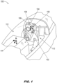
- FIG. 1 an aircraft 100 is shown.
- the aircraft 100 may be controlled by a pilot or other user 102 wearing a head worn display 104 (HWD; e.g., helmet-mounted display (HMD)).
- HWD head worn display
- the HWD 104 may include a display unit proper, e.g., integrated into a helmet 106 or visor worn by the user 102, and a head tracker system incorporating components fixed or otherwise attached to the helmet and within the cockpit or control area of the aircraft 100.
- the head tracker system may include an optical tracker at least partially integrated into the helmet 106.
- the optical tracker may include one or more cameras 108 or other like image sensors attached to the helmet 106 and configured to capture a continuous stream of image data corresponding to whatever the user 102 is looking at, or seeing, at any particular moment.
- the camera 108 may be fixed to the helmet 106, e.g., in a strapdown configuration, wherein the camera moves in unison with the helmet, and with the head of the user 102, and is said to be in a head-centered reference frame 110 ("head frame", h ).
- the camera 108 may be attached to the helmet 106 via one or more gimbals (not shown) capable of translating or rotating the camera relative to the helmet.
- the camera/s 108 may be tuned to operate in a variety of spectral bands, e.g., visible-range, near-infrared (NIR), short wave infrared (SWIR), long wave IR (LWIR).
- NIR near-infrared
- SWIR short wave infrared
- LWIR long wave IR
- the position and orientation (“pose") of the camera may be equivalent to the pose of the head of the user 102, or in a fixed relationship (e.g., constant rotation and/or translation) relative to the head pose.
- the head tracker includes head-frame inertial measurement units (IMU, hIMU) integrated into the helmet 106 and capable of tracking each translation and rotation of the head in the head frame 110, e.g., relative to a reference pose (for example, when the user's head is oriented straight ahead at eye level).
- IMU head-frame inertial measurement units
- the head tracker may estimate the head pose of the user 102 by detecting and decoding fiducial markers 112 within the cockpit environment.
- each fiducial marker 112 may be fixed within the cockpit environment at a position and orientation (e.g., relative to the aircraft 100) known to the head tracker.
- each fiducial marker 112 may include an encoded identifier (ID) decodable by the head tracker and uniquely distinguishing each fiducial marker, e.g., within a set of such markers disposed throughout the cockpit environment.
- ID encoded identifier
- the head tracker may compare the relative positions and/or orientations of each detected fiducial marker with their known positions and orientations and thereby estimate the position and orientation of the camera (and thus the head of the user 102) at the time the image was captured.
- the aircraft 100 may determine its position and orientation in both an absolute and a relative sense.
- the aircraft 100 may include an absolute positioning system, e.g., one or more global navigation satellite system (GNSS) based receivers configured to receive positioning signals from orbiting navigational satellites (e.g., GPS, GLONASS, Galileo, BeiDou, NavIC, QZSS). Based on the arrival times of signals received from multiple satellites, the GNSS based receivers can determine the aircraft's distance from each satellite at the time of reception and thereby determine an absolute position of the aircraft in an earth-centered, earth-fixed (ECEF) reference frame ("earth frame", e ) to a high degree of precision.
- ECEF earth-centered, earth-fixed
- the aircraft 100 may include IMUs capable of determining a relative position and orientation of the aircraft in a platform-centered/body-centered reference frame 114 (e.g., platform frame p , body frame b ) relative to a reference pose of the aircraft.
- a platform-centered/body-centered reference frame 114 e.g., platform frame p , body frame b
- the body-frame IMUs may track the relative position of the aircraft relative to a last known absolute position as determined by the GNSS receivers, as well as the orientation of the aircraft relative to its roll, pitch, and yaw axes (e.g., x-, y-, and z-axes).
- any IMU regardless of its reference frame, is subject to some degree of inherent drift and/or internal noise.
- a bIMU may track a relative position and orientation of the aircraft 100 in the body frame 114, e.g., relative to its last known absolute position and orientation, but as the elapsed time increases from this last known pose, so too will the level of inherent drift. Aiding devices may provide a means for correcting and compensating for inherent drift in inertial navigation systems.
- 10,216,265 discloses a numerically stable extended Kalman filter for relative navigation, or estimating a pose of a user's (102; e.g., pilot) head (e.g., as measured by the hIMU in the head frame 110) relative to the pose of an aircraft 100 (e.g., as measured by the bIMU in the body frame 114) carrying the user.
- Optical (or magnetic) aiding devices may provide estimated head pose measurements ("pose estimates") in six degrees of freedom (6DoF), e.g., translation along x-, y-, and z-axes (roll, pitch, yaw) and rotation relative to these axes.
- 6DoF six degrees of freedom
- 6DoF pose estimates provided by the aiding devices may correct for drift and noise in a relative navigational solution estimating the pose of the pilot's head relative to the aircraft in order to display flight guidance cues on the HWD 104 display unit.
- the relative navigation solution may include an error model estimating the probability of displaying hazardously misleading information (HMI) and bounding the accuracy of the head pose estimate by attempting to estimate and/or account for drift, noise, and other uncertainties within the navigational system.
- HMI hazardously misleading information
- system integrity requirements generally mandate this probability be no more than 1e -5 to 1e -7 (.00001 to .001 percent) per hour, or a pose error more than 0.5 to 4 inches in position and 3 to 20 milliradians (mrad) in orientation.
- the head tracking system 200 may include, in addition to the camera 108 and fiducial markers 110: optical tracker 202, head-frame IMU 204 (hIMU), body-frame IMU 206 (bIMU; also platform-frame IMU (pIMU)), Kalman filter 208 (e.g., extended Kalman filter (EKF), hybrid EKF), and pose projection module 210.
- optical tracker 202 head-frame IMU 204
- body-frame IMU 206 bIMU; also platform-frame IMU (pIMU)
- Kalman filter 208 e.g., extended Kalman filter (EKF), hybrid EKF
- pose projection module 210 e.g., pose projection module 210.
- the head-tracking system 200 may be configured in an inside-out configuration.
- the camera 108 and hIMU 204 may be attached to a helmet (106, FIG. 1 ) worn by the user (102, FIG. 1 ), such that image data 212 captured by the camera 108 and position and orientation (pose) data measured by the hIMU 204 may be in the head frame 110.
- image data 212 may be analyzed by the optical tracker 202 to identify image regions corresponding to the fiducial markers 112 and, by comparing the relative locations of the image regions to the known location of each fiducial marker, estimate the optical pose of the camera with respect to the three-dimensional (3D) constellation reference frame in which the known locations and orientations of each fiducial marker are defined (e.g., the body frame, when the locations and orientations of each fiducial marker in an inside-out configuration are fixed with respect to the aircraft (100, FIG. 1 )).
- the optical tracker 202 may determine an initial (e.g., coarse) pose estimate based on an initial match of image regions associated with detected fiducial markers 112 with the 3D position and orientation data for each marker.
- the optical tracker 202 may refine the initial pose estimate using a variety of techniques and/or algorithms, resulting in a refined (e.g., fine) head pose estimate 214.
- the refined head pose estimate 214 may include an error model (e.g., an H 1 protection level, or the probability of a single hypothetical fault with respect to a pose measurement, and/or pose covariance).
- the hIMU 204 may provide high-rate pose data (relative to the head frame 110) to the hybrid EKF 208. For example, at no less than a minimum rate (e.g., 200 Hz) the hIMU 204 may provide a measured 3D angular rate of motion and 3D translational acceleration in the head frame 110 (e.g., in addition to a precise timestamp for each measurement).
- a minimum rate e.g. 200 Hz
- the hIMU 204 may provide a measured 3D angular rate of motion and 3D translational acceleration in the head frame 110 (e.g., in addition to a precise timestamp for each measurement).
- the bIMU 206 and fiducial markers 112 may be oriented (e.g., in an inside-out configuration) in the platform-centered reference frame 114 (e.g., platform frame, body frame).
- the fiducial markers 112 may each be fixed in a position and orientation relative to the body frame 114 (e.g., a 3D constellation frame).
- the bIMU 206 may provide high-rate pose data (relative to the body frame 114) at a minimum rate similar to the hIMU 204 (e.g., measured 3D angular rate, measured 3D translational acceleration, timestamp at 200 Hz minimum).
- the bIMU 206 may additionally provide low-rate high-integrity pose data.
- the bIMU 206 may include a georeferenced (e.g., World Geodetic System 1984 (WGS84) or any appropriate ECEF) attitude and heading reference system (AHRS) in communication with a GNSS-driven absolute position receiver 218 (e.g., GPS.IRS).
- GRS84 World Geodetic System 1984
- AHRS attitude and heading reference system
- the bIMU may provide timestamped low-rate 3D georeferenced position data (e.g., in a north-east-down navigational reference frame n ; lat/long/alt in WGS84 coordinates; X, Y, Z in a like ECEF coordinate frame) and georeferenced 3D orientation data (e.g., pitch, roll, heading).
- position data e.g., in a north-east-down navigational reference frame n ; lat/long/alt in WGS84 coordinates; X, Y, Z in a like ECEF coordinate frame
- 3D orientation data e.g., pitch, roll, heading
- the low-rate high integrity georeferenced pose data and corresponding low-rate head pose estimates 214 provided by the optical tracker 202 may be the basis of a low-rate high integrity head pose solution sufficiently accurate for presentation to and use by high integrity applications running on the HWD 104.
- the low-rate high integrity solution may be updated by the hybrid EKF 208 based on the high-rate head-frame and platform-frame pose data provided by the hIMU 204 and bIMU 206, resulting in an updated hybrid head-to-body (h2b; also head-to-platform (h2p)) direction cosine matrix (DCM) 220 output by the hybrid EKF, corresponding to a quaternion q h b t k expressing a rotation of the head frame 110 relative to the body frame 114 at a current time t k .
- h2b also head-to-platform (h2p)
- DCM direction cosine matrix
- the head tracking system 200 is a magnetic (rather than optical) head tracking system wherein the cameras 108, fiducial markers 112, and optical tracker 202 are replaced by a magnetometer capable of detecting a well-known magnetic field source, which detection provides an alternative basis to the optical tracker for determining a transformation between Oh and Oa reference frames.
- a magnetic-field based head tracking system is referenced and described by the related patent application having Serial No. 17/953,227 .
- the pose projection module 210 may comprise encoded instructions executable by processors of the head tracker system 200 (e.g., similarly to the optical tracker 202 and hybrid extended Kalman filter 208). For example, the pose projection module 210 may receive, for the current time t k , an updated pose solution 220 (e.g., the hybrid h2b quaternion) from the hybrid EKF 208, angular rate measurements from the hIMU 204 and bIMU 206, and a projection time ⁇ T corresponding to a display latency estimate.
- an updated pose solution 220 e.g., the hybrid h2b quaternion
- the output 222 of the pose projection module 210 may be an updated h2b DCM corresponding to a quaternion q h b t k + ⁇ expressing the rotation of the head frame 110 relative to the body frame 114 projected forward to the subsequent time t k + ⁇ T to predict an orientation of the HWD 104 relative to the aircraft/mobile platform 100 at the subsequent time.
- the head tracking system 200 may include optical flow sensors 216.
- optical flow sensors 216 may analyze the image data 212 on a frame-by-frame basis and estimate, based on changes to the image data between frames and the output rate of the optical tracker 202, a 3D relative angular rate of motion of the head frame relative to the body frame.
- the pose prediction module 210 may, additionally or alternatively, determine relative angular rate based on head-frame and body-frame angular rates received from, e.g., the hIMU 204 and bIMU 206, or receive relative angular rate measurements as determined by the optical flow sensors 216.
- the pose projection module 210 is shown.
- the pose projection module 210 may include sub-modules 210a, 210b, 210c ... 210n dedicated to individual rotational axes.
- the pose projection module may include three sub-modules 210a, 210b, 210c dedicated to projecting forward an orientation of the head frame (110, FIG. 1 ) relative to the body frame (114, FIG. 1 ) with respect to, respectively, a roll axis or x-axis (210a), a pitch axis or y-axis (210b), and a yaw axis or z-axis (210c).
- the x-axis pose projection module 210a may receive (for current time t k ) x-axis angular rate measurements (e.g., angular rate ⁇ i
- x-axis angular rate measurements e.g., angular rate ⁇ i
- the pose projection module 210a may receive a relative angular rate 302a determined by the optical flow sensors 216.
- each pose projection module 210a-210c may include a selector 302b for selecting a relative angular rate from the relative angular rate 302 as determined by the pose projection module 210a-210c based on the received head-frame and body-frame angular rates ⁇ i
- the pose projection module 210a 1 may determine a current relative angular rate 302 ⁇ b
- h h ⁇ i
- each pose projection module 210a may be associated with a projection time ⁇ T corresponding to a nominal estimate of display system latency and to a future prediction time (e.g., in seconds) relative to the current time t k and at which the current estimated head pose solution 220 may be predicted.
- a projection time 304 ( ⁇ ⁇ ,i ) may be determined for use with the relative angular rate 302, and a projection time 304a ( ⁇ ⁇ ,i ) may be determined for use with the relative angular acceleration 306 (as shown below by equations 11 and 12).
- the projection time ⁇ T may be predetermined by the head tracking system (200, FIG. 2 ), e.g., retrieved from memory or hard-coded into system firmware based on an estimated nominal latency within the HWD 104, and the projection times 304, 304a may use the projection time ⁇ T for the projection times ⁇ ⁇ ,i ), ⁇ ⁇ ,i ).
- the projection time 304, 304a determined at a current time t k may be dynamically adjusted, e.g., relative to a prior time t k - 1 at which the head pose solution 220 was calculated and/or updated. For example, when head motion is relatively low, e.g., meets or deceeds a threshold minimum level, the head tracking system 200 may reduce the projection time 304, 304a to minimize jitter as disclosed below. 1 With respect to the following paragraphs, each reference to operations of the x-axis pose projection module 210a may likewise apply to the pose projection modules 210b, 210c with respect to the y- and z-axes.
- the pose projection module 210a may determine a relative angular acceleration ⁇ ⁇ b
- a sampling period or single-sample delay 308 e.g., a delay of dt imu seconds, based on an IMU sampling rate or, when the relative angular rate 302 is determined by the optical flow sensors 216, a delay of dt opt seconds based on an optical tracker output rate.
- h h t k ⁇ 1 1 dt imu a ⁇ b
- the head tracking system 200 may apply filtering (e.g., finite impulse response (FIR) filter, moving average filter with configurable buffer length) to the relative angular acceleration 306.
- filtering e.g., finite impulse response (FIR) filter, moving average filter with configurable buffer length
- the pose projection module 210a may calculate a total angular increment vector ⁇ b
- h h ⁇ b
- the pose projection module 210a may receive the updated pose solution 220 for the current time t k , (e.g., the h2b quaternion q h b t k ) from the hybrid EKF 208.
- the pose projection module 210 may advance (312) the updated pose solution 220 (e.g., the h2b quaternion q h b t k ) along one or more of the x-, y-, and z-axes.
- the updated pose solution 220 e.g., the h2b quaternion q h b t k
- the resulting output of the pose projection module 210 may be an updated or projected h2b estimated pose solution 222 corresponding to a projected quaternion q h b t k + ⁇ expressing a predicted rotational orientation of the head frame 110 relative to the body frame 114 at the subsequent time t k + ⁇ T .
- the projection time 304, 304a may be reduced when head motion is low to reduce high frequency errors in the projected pose solution 222.
- the projection time 304, 304a may be adjusted on an axis-by-axis basis (e.g., reduced for one or more axes, on the basis that relatively low head motion reduces the effect of latency on the conformality of symbology rendered by the HWD 104, and likewise reduces the need for pose prediction).
- equation 10 shows a scalar angular increment component ⁇ b
- h , i h for axis i (where i x , y , or z ) as a function of scalar angular rate component ⁇ b
- h , i h ⁇ b
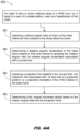
- the method 400 may be implemented by the pose projection module 210 and may include the following steps.
- the pose projection module selects a relative angular rate of motion of the head frame relative to the body frame.
- the pose projection module determines the relative angular rate based on a head-frame angular rate received from a head-mounted IMU (hIMU) and a body-frame angular rate received from a platformmounted/body-mounted IMU (bIMU).
- the relative angular rate is determined, and received from, optical flow sensors connected to an optical head-tracking system of the HWD. In some embodiments, if both options are available the pose projection module may select one or the other as a relative angular rate for use in pose projection.
- the pose projection module determines a relative angular acceleration of the head frame relative to the body frame, and relative to a current time of validity, by sampling the relative angular rate.
- the pose projection module adjusts a projection time defining how far into the future (e.g., ahead of the current time of validity) the pose of the HWD will be projected.
- the projection times for use with the relative angular rate and the relative angular acceleration may be predetermined and hardcoded into firmware and/or stored to memory.
- the projection time may be reduced to reduce high frequency errors when headtracker motion is low and pose prediction is a lower priority.
- the pose projection module determines a first angular increment vector based on the determined relative angular rate and associated projection time.
- the pose projection module determines a second angular increment vector based on the determined relative angular acceleration and associated projection time.
- the relative angular acceleration may be based on a set of N samples of the relative angular rate (e.g., at a predetermined sampling rate, and wherein N is an integer greater than one).
- the relative angular acceleration may be filtered (e.g., based on a moving average of the set of N samples or any appropriate like finite impulse response (FIR) filter).
- FIR finite impulse response
- the pose projection module determines a total angular increment vector associated with the rotational axis by combining the first and second angular increment vectors associated with the relative angular rate and the relative angular acceleration. For example, each rotational axis will have an associated total angular increment vector.
- the pose projection module receives a pose estimate, e.g., an estimated position and/or orientation of the HWD relative to the body frame as determined by a Kalman filter of the head tracking system and corresponding to the current time of validity.
- a pose estimate e.g., an estimated position and/or orientation of the HWD relative to the body frame as determined by a Kalman filter of the head tracking system and corresponding to the current time of validity.
- the pose projection module determines a projected pose of the HWD relative to the body frame, projecting the current pose estimate received from the head tracking system forward to the projected time, by adjusting the current pose estimate based on the total angular increment vector determined for each rotational axis.
- the pose projection module may project the current pose estimate forward in time by adjusting the estimated orientation of the HWD relative to one or more rotational axes, depending on each axis-specific total angular increment vector.
- embodiments of the methods disclosed herein may include one or more of the steps described herein. Further, such steps may be carried out in any desired order and two or more of the steps may be carried out simultaneously with one another. Two or more of the steps disclosed herein may be combined in a single step, and in some embodiments, one or more of the steps may be carried out as two or more sub-steps. Further, other steps or sub-steps may be carried in addition to, or as substitutes to one or more of the steps disclosed herein.
Landscapes
- Engineering & Computer Science (AREA)
- Theoretical Computer Science (AREA)
- Physics & Mathematics (AREA)
- General Engineering & Computer Science (AREA)
- General Physics & Mathematics (AREA)
- Human Computer Interaction (AREA)
- Radar, Positioning & Navigation (AREA)
- Remote Sensing (AREA)
- Computer Vision & Pattern Recognition (AREA)
- Multimedia (AREA)
- Optics & Photonics (AREA)
- Automation & Control Theory (AREA)
- Length Measuring Devices By Optical Means (AREA)
Abstract
Description
- In order to accurately represent earth-fixed symbology via a head-worn display (HWD) or helmet-mounted display (HMD) worn by an aircraft pilot or operator, the pose (e.g., position and orientation) of the pilot's head relative to the aircraft must be continually estimated in a precise high-integrity fashion. The HWD must account for the pilot's head pose relative to the aircraft and the aircraft's pose relative to an earth-centered earth-fixed (ECEF) reference frame (e.g., which may involve additional intermediate reference frames) so that the positioning of earth-fixed symbology does not render it hazardously misleading information (HMI).
- However, a significant challenge to conformal rendering of earth-fixed symbology by the HWD is presented by display system latency. For example, in the presence of sustained head motion on the part of the pilot, uncompensated latency may cause earth-fixed symbology to drift from a conformal alignment.
- In a first aspect, a system for predicting a position and/or orientation (pose) of an HWD relative to a platform or body frame of an aircraft or other mobile platform is disclosed. In embodiments, the system selects a relative angular rate of motion of a head-centered reference frame relative to a body-centered/platform-centered reference frame. The system determines, by sampling the relative angular rate, a relative head-to-body angular acceleration. Based on a projection time associated with estimated system latency within the HWD, the system determines angular increment vectors for the relative angular rate and relative angular acceleration. The system receives a current estimated head pose solution from the HWD headtracker and adjusts the head pose solution with respect to the received angular increment vectors for each rotational axis to project the head pose solution forward by the projection time. The resulting projected head pose solution can predict a rotational orientation of the head frame relative to the body frame at a desired future time to counteract HWD system latency, e.g., when sustained head motion is relatively high.
- In some embodiments, the projection time is predetermined, e.g., hard-coded into system firmware or stored to memory.
- In some embodiments, the projection time is reduced, e.g., when head motion is at or below a minimum level and the corresponding reduced system latency renders pose prediction a lower priority.
- In some embodiments, the system applies filtering to the relative angular acceleration.
- In some embodiments, the system determines the projected head pose solution by adjusting the estimated rotational orientation of the head frame relative to the body frame with respect to each rotational axis, based on a total angular increment vector determined for that rotational axis.
- In some embodiments, the system receives from a head-mounted IMU (hIMU; e.g., fixed to the helmet or user's head) an angular rate of motion of the head reference frame relative to an inertial frame and receives from a body-mounted/platform-mounted IMU (bIMU, pIMU; e.g., fixed to the aircraft or mobile platform) an angular rate of motion of the body reference frame relative to the inertial frame, and determines the relative angular rate of motion based on the received head-frame and body-frame angular rates.
- In some embodiments, the system selects a relative angular rate of motion determined by, and received from, optical flow sensors connected to an optical head tracking system of the HWD.
- In a further aspect, a computer-assisted method for predicting a future head pose of an HWD (e.g., relative to a body frame of an aircraft or mobile platform) is also disclosed. In embodiments, the method includes, for each rotational axis of the HWD (e.g., x, y, z), selecting a relative angular rate of motion (e.g., of a head reference frame relative to a body reference frame (e.g., platform reference frame). The method includes determining a relative angular acceleration (e.g., head-frame relative to body-frame) at a current time by sampling the relative angular rate. The method includes adjusting a projection time relative to the current time, the projection time based on an estimated display system latency and determining the future time at which the relative head pose estimate (e.g., the rotational orientation of the head frame relative to the body frame) will be predicted. The method includes (e.g., still for each rotational axis) determining, based on the projection time, angular increment vectors for the relative angular rate and relative angular acceleration. The method includes determining a total angular increment vector for a particular rotational axis by combining the angular increment vectors for the relative angular rate and relative angular acceleration. The method includes receiving from a headtracking system of the HWD a current estimated head pose solution, e.g., a current estimate of the position and orientation of the head frame relative to the body frame. The method includes adjusting the current head pose solution with respect to each rotational axis based on the total angular increment vector determined for that rotational axis, the adjusted head pose solution capable of predicting the head-frame to body-frame rotational orientation at the desired future time.
- In some embodiments, the projection time is predetermined based on an a priori system latency estimate and, e.g., hard-coded into system firmware or stored to memory.
- In some embodiments, the method includes reducing the projection time if head frame movement meets or deceeds a minimum level.
- In some embodiments, the method includes filtering the relative angular acceleration based on a moving average of N samples of the relative angular rate.
- In some embodiments, the method includes adjusting the estimated head pose solution by adjusting the estimated rotational orientation of the head frame relative to the body frame with respect to one or more rotational axes of the HWD, based on the determined total angular increment vectors for each rotational axis.
- In some embodiments, the method includes selecting a relative angular rate by receiving head-frame angular rate of motion (e.g., relative to an arbitrary inertial frame) from a head-mounted IMU and a body-frame angular rate of motion (e.g., relative to the same inertial frame) from a body-mounted IMU. For example, the method includes determining (e.g., for each rotational axis) the relative angular rate based on the received head-frame and body-frame angular rates.
- In some embodiments, the method includes selecting a relative angular rate determined by, and received from, optical flow sensors connected to an optical head tracking system of the HWD.
- This Summary is provided solely as an introduction to subject matter that is fully described in the Detailed Description and Drawings. The Summary should not be considered to describe essential features nor be used to determine the scope of the Claims. Moreover, it is to be understood that both the foregoing Summary and the following Detailed Description are example and explanatory only and are not necessarily restrictive of the subject matter claimed.
- The detailed description is described with reference to the accompanying figures. The use of the same reference numbers in different instances in the description and the figures may indicate similar or identical items. Various embodiments or examples ("examples") of the present disclosure are disclosed in the following detailed description and the accompanying drawings. The drawings are not necessarily to scale. In general, operations of disclosed processes may be performed in an arbitrary order, unless otherwise provided in the claims. In the drawings:
-
FIG. 1 is an illustration of an aircraft cockpit environment and a head worn display (HWD) worn by a pilot of the aircraft, the HWD including a head tracking system in an inside-out configuration according to example embodiments of this disclosure; -
FIG. 2 is a block diagram of the head tracking system incorporating an extended Kalman filter (EKF) ofFIG. 1 ; -
FIG. 3 is an operational flow diagram of a pose projection module of the head tracking system ofFIG. 1 ; - and
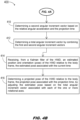
FIGS. 4A and4B are flow diagrams illustrating a method for predicting a position or orientation (pose) of an HWD relative to a platform/body reference frame at a future time according to example embodiments of this disclosure. - Before explaining one or more embodiments of the disclosure in detail, it is to be understood that the embodiments are not limited in their application to the details of construction and the arrangement of the components or steps or methodologies set forth in the following description or illustrated in the drawings. In the following detailed description of embodiments, numerous specific details may be set forth in order to provide a more thorough understanding of the disclosure. However, it will be apparent to one of ordinary skill in the art having the benefit of the instant disclosure that the embodiments disclosed herein may be practiced without some of these specific details. In other instances, well-known features may not be described in detail to avoid unnecessarily complicating the instant disclosure.
- As used herein a letter following a reference numeral is intended to reference an embodiment of the feature or element that may be similar, but not necessarily identical, to a previously described element or feature bearing the same reference numeral (e.g., 1, 1a, 1b). Such shorthand notations are used for purposes of convenience only and should not be construed to limit the disclosure in any way unless expressly stated to the contrary.
- Further, unless expressly stated to the contrary, "or" refers to an inclusive or and not to an exclusive or. For example, a condition A or B is satisfied by any one of the following: A is true (or present) and B is false (or not present), A is false (or not present) and B is true (or present), and both A and B are true (or present).
- In addition, use of "a" or "an" may be employed to describe elements and components of embodiments disclosed herein. This is done merely for convenience and "a" and "an" are intended to include "one" or "at least one," and the singular also includes the plural unless it is obvious that it is meant otherwise.
- Finally, as used herein any reference to "one embodiment" or "some embodiments" means that a particular element, feature, structure, or characteristic described in connection with the embodiment is included in at least one embodiment disclosed herein. The appearances of the phrase "in some embodiments" in various places in the specification are not necessarily all referring to the same embodiment, and embodiments may include one or more of the features expressly described or inherently present herein, or any combination or sub-combination of two or more such features, along with any other features which may not necessarily be expressly described or inherently present in the instant disclosure.
- Broadly speaking, embodiments of the inventive concepts disclosed herein are directed to systems and methods for compensating for display system latency in a HWD (e.g., a helmet-mounted display (HMD), visor display, or other head-worn display worn to an aircraft pilot or other operator of a mobile platform) by projecting head pose estimates forward in time in order to predict a head pose of the HWD (e.g., an orientation of the head-centered reference frame of the HWD relative to the platform-centered reference frame of the mobile platform) to a future time. By predicting future head poses by projecting current head pose estimates into the future based on angular rate/ acceleration measurements and system display latency estimates, lower perceived latency and reduced risk of HMI presentation may be achieved even with lower-cost but higherlatency commercial off the shelf (COTS) display systems. Further, while pose prediction may be maximally effective during periods of sustained high head motion, projection time may be dynamically reduced to minimize jitter when head motion is low and the correspondingly lower system latency makes pose prediction less necessary.
- Referring now to
FIG. 1 , anaircraft 100 is shown. - In embodiments, the
aircraft 100 may be controlled by a pilot orother user 102 wearing a head worn display 104 (HWD; e.g., helmet-mounted display (HMD)). For example, theHWD 104 may include a display unit proper, e.g., integrated into ahelmet 106 or visor worn by theuser 102, and a head tracker system incorporating components fixed or otherwise attached to the helmet and within the cockpit or control area of theaircraft 100. - In embodiments, the head tracker system may include an optical tracker at least partially integrated into the
helmet 106. For example, the optical tracker may include one ormore cameras 108 or other like image sensors attached to thehelmet 106 and configured to capture a continuous stream of image data corresponding to whatever theuser 102 is looking at, or seeing, at any particular moment. Thecamera 108 may be fixed to thehelmet 106, e.g., in a strapdown configuration, wherein the camera moves in unison with the helmet, and with the head of theuser 102, and is said to be in a head-centered reference frame 110 ("head frame", h ). Alternatively, thecamera 108 may be attached to thehelmet 106 via one or more gimbals (not shown) capable of translating or rotating the camera relative to the helmet. In embodiments, the camera/s 108 may be tuned to operate in a variety of spectral bands, e.g., visible-range, near-infrared (NIR), short wave infrared (SWIR), long wave IR (LWIR). - In embodiments, when the
camera 108 is in the strapdown configuration, the position and orientation ("pose") of the camera may be equivalent to the pose of the head of theuser 102, or in a fixed relationship (e.g., constant rotation and/or translation) relative to the head pose. For example, when theuser 102 moves their head (e.g., translates, rotates), the head tracker includes head-frame inertial measurement units (IMU, hIMU) integrated into thehelmet 106 and capable of tracking each translation and rotation of the head in thehead frame 110, e.g., relative to a reference pose (for example, when the user's head is oriented straight ahead at eye level). - In embodiments, the head tracker may estimate the head pose of the
user 102 by detecting and decodingfiducial markers 112 within the cockpit environment. For example, eachfiducial marker 112 may be fixed within the cockpit environment at a position and orientation (e.g., relative to the aircraft 100) known to the head tracker. Further, eachfiducial marker 112 may include an encoded identifier (ID) decodable by the head tracker and uniquely distinguishing each fiducial marker, e.g., within a set of such markers disposed throughout the cockpit environment. - In embodiments, by identifying image regions corresponding to each
fiducial marker 112 from within image data captured by thecamera 108, the head tracker may compare the relative positions and/or orientations of each detected fiducial marker with their known positions and orientations and thereby estimate the position and orientation of the camera (and thus the head of the user 102) at the time the image was captured. - In embodiments, the
aircraft 100 may determine its position and orientation in both an absolute and a relative sense. For example, theaircraft 100 may include an absolute positioning system, e.g., one or more global navigation satellite system (GNSS) based receivers configured to receive positioning signals from orbiting navigational satellites (e.g., GPS, GLONASS, Galileo, BeiDou, NavIC, QZSS). Based on the arrival times of signals received from multiple satellites, the GNSS based receivers can determine the aircraft's distance from each satellite at the time of reception and thereby determine an absolute position of the aircraft in an earth-centered, earth-fixed (ECEF) reference frame ("earth frame", e ) to a high degree of precision. Similarly, theaircraft 100 may include IMUs capable of determining a relative position and orientation of the aircraft in a platform-centered/body-centered reference frame 114 (e.g., platform frame p , body frame b ) relative to a reference pose of the aircraft. For example, if theaircraft 100 enters an airspace where GNSS services are unavailable or unreliable, the body-frame IMUs (bIMU) may track the relative position of the aircraft relative to a last known absolute position as determined by the GNSS receivers, as well as the orientation of the aircraft relative to its roll, pitch, and yaw axes (e.g., x-, y-, and z-axes). - Any IMU, regardless of its reference frame, is subject to some degree of inherent drift and/or internal noise. For example, as noted above a bIMU may track a relative position and orientation of the
aircraft 100 in thebody frame 114, e.g., relative to its last known absolute position and orientation, but as the elapsed time increases from this last known pose, so too will the level of inherent drift. Aiding devices may provide a means for correcting and compensating for inherent drift in inertial navigation systems. For example,U.S. Patent No. 10,216,265 HWD 104 display unit. Further, the relative navigation solution may include an error model estimating the probability of displaying hazardously misleading information (HMI) and bounding the accuracy of the head pose estimate by attempting to estimate and/or account for drift, noise, and other uncertainties within the navigational system. For example, system integrity requirements generally mandate this probability be no more than 1e-5 to 1e-7 (.00001 to .001 percent) per hour, or a pose error more than 0.5 to 4 inches in position and 3 to 20 milliradians (mrad) in orientation. - Referring now to
FIG. 2 , a head tracking system 200 ("headtracker") for anHWD 104 is shown. Thehead tracking system 200 may include, in addition to thecamera 108 and fiducial markers 110:optical tracker 202, head-frame IMU 204 (hIMU), body-frame IMU 206 (bIMU; also platform-frame IMU (pIMU)), Kalman filter 208 (e.g., extended Kalman filter (EKF), hybrid EKF), and poseprojection module 210. - In embodiments, the head-tracking
system 200 may be configured in an inside-out configuration. For example, thecamera 108 andhIMU 204 may be attached to a helmet (106,FIG. 1 ) worn by the user (102,FIG. 1 ), such thatimage data 212 captured by thecamera 108 and position and orientation (pose) data measured by thehIMU 204 may be in thehead frame 110. In embodiments,image data 212 may be analyzed by theoptical tracker 202 to identify image regions corresponding to thefiducial markers 112 and, by comparing the relative locations of the image regions to the known location of each fiducial marker, estimate the optical pose of the camera with respect to the three-dimensional (3D) constellation reference frame in which the known locations and orientations of each fiducial marker are defined (e.g., the body frame, when the locations and orientations of each fiducial marker in an inside-out configuration are fixed with respect to the aircraft (100,FIG. 1 )). For example, theoptical tracker 202 may determine an initial (e.g., coarse) pose estimate based on an initial match of image regions associated with detectedfiducial markers 112 with the 3D position and orientation data for each marker. In embodiments, theoptical tracker 202 may refine the initial pose estimate using a variety of techniques and/or algorithms, resulting in a refined (e.g., fine) head pose estimate 214. For example, the refined head pose estimate 214 may include an error model (e.g., an H1 protection level, or the probability of a single hypothetical fault with respect to a pose measurement, and/or pose covariance). - In embodiments, the
hIMU 204 may provide high-rate pose data (relative to the head frame 110) to thehybrid EKF 208. For example, at no less than a minimum rate (e.g., 200 Hz) thehIMU 204 may provide a measured 3D angular rate of motion and 3D translational acceleration in the head frame 110 (e.g., in addition to a precise timestamp for each measurement). - In embodiments, the
bIMU 206 andfiducial markers 112 may be oriented (e.g., in an inside-out configuration) in the platform-centered reference frame 114 (e.g., platform frame, body frame). For example, thefiducial markers 112 may each be fixed in a position and orientation relative to the body frame 114 (e.g., a 3D constellation frame). In embodiments, thebIMU 206 may provide high-rate pose data (relative to the body frame 114) at a minimum rate similar to the hIMU 204 (e.g., measured 3D angular rate, measured 3D translational acceleration, timestamp at 200 Hz minimum). - In embodiments, the
bIMU 206 may additionally provide low-rate high-integrity pose data. For example, thebIMU 206 may include a georeferenced (e.g., World Geodetic System 1984 (WGS84) or any appropriate ECEF) attitude and heading reference system (AHRS) in communication with a GNSS-driven absolute position receiver 218 (e.g., GPS.IRS). In embodiments, at a lower rate (e.g., 20 Hz) than the high-rate pose data produced by thehIMU 204 andbIMU 206, the bIMU may provide timestamped low-rate 3D georeferenced position data (e.g., in a north-east-down navigational reference frame n ; lat/long/alt in WGS84 coordinates; X, Y, Z in a like ECEF coordinate frame) and georeferenced 3D orientation data (e.g., pitch, roll, heading). In embodiments, the low-rate high integrity georeferenced pose data and corresponding low-rate head pose estimates 214 provided by theoptical tracker 202 may be the basis of a low-rate high integrity head pose solution sufficiently accurate for presentation to and use by high integrity applications running on theHWD 104. For example, the low-rate high integrity solution may be updated by thehybrid EKF 208 based on the high-rate head-frame and platform-frame pose data provided by thehIMU 204 andbIMU 206, resulting in an updated hybrid head-to-body (h2b; also head-to-platform (h2p)) direction cosine matrix (DCM) 220 output by the hybrid EKF, corresponding to a quaternion
head frame 110 relative to thebody frame 114 at a current time tk . - In some embodiments, the
head tracking system 200 is a magnetic (rather than optical) head tracking system wherein thecameras 108,fiducial markers 112, andoptical tracker 202 are replaced by a magnetometer capable of detecting a well-known magnetic field source, which detection provides an alternative basis to the optical tracker for determining a transformation between Oh and Oa reference frames. For example, such a magnetic-field based head tracking system is referenced and described by the related patent application having SerialNo. 17/953,227 - In embodiments, the
pose projection module 210 may comprise encoded instructions executable by processors of the head tracker system 200 (e.g., similarly to theoptical tracker 202 and hybrid extended Kalman filter 208). For example, thepose projection module 210 may receive, for the current time tk , an updated pose solution 220 (e.g., the hybrid h2b quaternion) from thehybrid EKF 208, angular rate measurements from thehIMU 204 andbIMU 206, and a projection time δT corresponding to a display latency estimate. Theoutput 222 of thepose projection module 210 may be an updated h2b DCM corresponding to a quaternion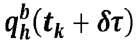
head frame 110 relative to thebody frame 114 projected forward to the subsequent time tk + δT to predict an orientation of theHWD 104 relative to the aircraft/mobile platform 100 at the subsequent time. - In some embodiments, the
head tracking system 200 may includeoptical flow sensors 216. For example,optical flow sensors 216 may analyze theimage data 212 on a frame-by-frame basis and estimate, based on changes to the image data between frames and the output rate of theoptical tracker 202, a 3D relative angular rate of motion of the head frame relative to the body frame. Accordingly, thepose prediction module 210 may, additionally or alternatively, determine relative angular rate based on head-frame and body-frame angular rates received from, e.g., thehIMU 204 andbIMU 206, or receive relative angular rate measurements as determined by theoptical flow sensors 216. - Referring to
FIG. 3 , thepose projection module 210 is shown. - In embodiments, the
pose projection module 210 may include sub-modules 210a, 210b, 210c ... 210n dedicated to individual rotational axes. For example, with respect to an HWD (104,FIG. 1 ) and headtracker (200,FIG. 2 ) wherein the estimated head pose (214,FIG. 2 ) is in six degrees of freedom (6DoF), the pose projection module may include three sub-modules 210a, 210b, 210c dedicated to projecting forward an orientation of the head frame (110,FIG. 1 ) relative to the body frame (114,FIG. 1 ) with respect to, respectively, a roll axis or x-axis (210a), a pitch axis or y-axis (210b), and a yaw axis or z-axis (210c). - In embodiments, the x-axis pose
projection module 210a (e.g., along with the corresponding y-axis and z-axis modules 
head frame 110 with respect to an arbitrary inertial frame in head-frame coordinates, angular rate
body frame 114 relative to the inertial frame in body-frame coordinates) from thehIMU 204 andbIMU 206 respectively. Alternatively, as noted above, thepose projection module 210a may receive a relativeangular rate 302a determined by theoptical flow sensors 216. In some embodiments, e.g., if thehead tracking system 200 includes bothhIMU 204/bIMU) 206 andoptical flow sensors 216, each poseprojection module 210a-210c may include aselector 302b for selecting a relative angular rate from the relativeangular rate 302 as determined by thepose projection module 210a-210c based on the received head-frame and body-frame angular rates
- In embodiments, the
pose projection module 210a1 may determine a current relativeangular rate 302


angular rate 302, each poseprojection module 210a may be associated with a projection time δT corresponding to a nominal estimate of display system latency and to a future prediction time (e.g., in seconds) relative to the current time tk and at which the current estimated head posesolution 220 may be predicted. For example, based on the projection time δT , a projection time 304 ( δτω,i ) may be determined for use with the relativeangular rate 302, and aprojection time 304a ( δτα,i ) may be determined for use with the relative angular acceleration 306 (as shown below by equations 11 and 12). For example, the projection time δT may be predetermined by the head tracking system (200,FIG. 2 ), e.g., retrieved from memory or hard-coded into system firmware based on an estimated nominal latency within theHWD 104, and theprojection times projection time solution 220 was calculated and/or updated. For example, when head motion is relatively low, e.g., meets or deceeds a threshold minimum level, thehead tracking system 200 may reduce theprojection time
1 With respect to the following paragraphs, each reference to operations of the x-axis poseprojection module 210a may likewise apply to thepose projection modules - In embodiments, the
pose projection module 210a may determine a relative angular acceleration
angular rate 302 at a predetermined sampling rate, e.g., according to a sampling period or single-sample delay 308 (e.g., a delay of dtimu seconds, based on an IMU sampling rate or, when the relativeangular rate 302 is determined by theoptical flow sensors 216, a delay of dtopt seconds based on an optical tracker output rate). By way of a non-limiting example:

- In some embodiments, the
head tracking system 200 may apply filtering (e.g., finite impulse response (FIR) filter, moving average filter with configurable buffer length) to the relativeangular acceleration 306. For example:
- In embodiments, the
pose projection module 210a may calculate a total angular increment vector
angular rate 302 and relativeangular acceleration 306. For example:
- In embodiments, the
pose projection module 210a may receive the updatedpose solution 220 for the current time tk , (e.g., the h2b quaternion
hybrid EKF 208. Based on the determined total angular increment vector

pose projection modules pose projection module 210 may advance (312) the updated pose solution 220 (e.g., the h2b quaternion
pose projection module 210 may be an updated or projected h2b estimated posesolution 222 corresponding to a projected quaternion
head frame 110 relative to thebody frame 114 at the subsequent time tk + δT . For example, the projected h2b quaternion



- In some embodiments, as noted above, the
projection time pose solution 222. For example, based on the magnitudes of the relativeangular rate angular acceleration 306, theprojection time HWD 104, and likewise reduces the need for pose prediction). - In embodiments, given an initial projection time δT the angular increment vector equation 5 above may be modified slightly, resulting in equation 10 below. For example, equation 10 shows a scalar angular increment component


angular rate 302, a scalar angular acceleration component


- Referring now to
FIG. 4A , themethod 400 may be implemented by thepose projection module 210 and may include the following steps. - At a
step 402, for each rotational axis of a set of rotational axes with which the head tracking system of the HWD determines a pose (e.g., x-, y-, and z-axes; roll, pitch, and yaw axes), the pose projection module selects a relative angular rate of motion of the head frame relative to the body frame. In some embodiments, the pose projection module determines the relative angular rate based on a head-frame angular rate received from a head-mounted IMU (hIMU) and a body-frame angular rate received from a platformmounted/body-mounted IMU (bIMU). In some embodiments, the relative angular rate is determined, and received from, optical flow sensors connected to an optical head-tracking system of the HWD. In some embodiments, if both options are available the pose projection module may select one or the other as a relative angular rate for use in pose projection. - At a
step 404, the pose projection module determines a relative angular acceleration of the head frame relative to the body frame, and relative to a current time of validity, by sampling the relative angular rate. - At a
step 406, the pose projection module adjusts a projection time defining how far into the future (e.g., ahead of the current time of validity) the pose of the HWD will be projected. For example, the projection times for use with the relative angular rate and the relative angular acceleration may be predetermined and hardcoded into firmware and/or stored to memory. In some embodiments, if sustained head motion is low enough (e.g., at or less than a threshold minimum amount), the projection time may be reduced to reduce high frequency errors when headtracker motion is low and pose prediction is a lower priority. - At a
step 408, the pose projection module determines a first angular increment vector based on the determined relative angular rate and associated projection time. - Referring also to
FIG. 4B , at astep 410, the pose projection module determines a second angular increment vector based on the determined relative angular acceleration and associated projection time. For example, the relative angular acceleration may be based on a set of N samples of the relative angular rate (e.g., at a predetermined sampling rate, and wherein N is an integer greater than one). Accordingly, the relative angular acceleration may be filtered (e.g., based on a moving average of the set of N samples or any appropriate like finite impulse response (FIR) filter). - At a
step 412, the pose projection module determines a total angular increment vector associated with the rotational axis by combining the first and second angular increment vectors associated with the relative angular rate and the relative angular acceleration. For example, each rotational axis will have an associated total angular increment vector. - At a
step 414, the pose projection module receives a pose estimate, e.g., an estimated position and/or orientation of the HWD relative to the body frame as determined by a Kalman filter of the head tracking system and corresponding to the current time of validity. - At a
step 416, the pose projection module determines a projected pose of the HWD relative to the body frame, projecting the current pose estimate received from the head tracking system forward to the projected time, by adjusting the current pose estimate based on the total angular increment vector determined for each rotational axis. For example, the pose projection module may project the current pose estimate forward in time by adjusting the estimated orientation of the HWD relative to one or more rotational axes, depending on each axis-specific total angular increment vector. - It is to be understood that embodiments of the methods disclosed herein may include one or more of the steps described herein. Further, such steps may be carried out in any desired order and two or more of the steps may be carried out simultaneously with one another. Two or more of the steps disclosed herein may be combined in a single step, and in some embodiments, one or more of the steps may be carried out as two or more sub-steps. Further, other steps or sub-steps may be carried in addition to, or as substitutes to one or more of the steps disclosed herein.
- Although inventive concepts have been described with reference to the embodiments illustrated in the attached drawing figures, equivalents may be employed and substitutions made herein without departing from the scope of the claims. Components illustrated and described herein are merely examples of a system/device and components that may be used to implement embodiments of the inventive concepts and may be replaced with other devices and components without departing from the scope of the claims. Furthermore, any dimensions, degrees, and/or numerical ranges provided herein are to be understood as non-limiting examples unless otherwise specified in the claims.
Claims (14)
- A system (200) for predicting at least one of a position or an orientation of a head worn display (104), HWD, the system comprising:
at least one processor operatively coupled to an HWD worn on a head of a user (102) of a mobile platform, the at least one processor configurable by processor-executable instructions to:for each of one or more rotational axes of the HWD:determine, based on one or more of 1) a head-frame (110) angular rate of motion of a head reference frame relative to an inertial frame and 2) a body-frame (114) angular rate of motion of a body reference frame relative to the inertial frame, a relative angular rate of motion of the head reference frame relative to the body reference frame;determine, by sampling the relative angular rate, a relative angular acceleration of the head reference frame relative to the body reference frame, the relative angular acceleration associated with a current time;adjust a projection time relative to the current time, the projected time associated with at least one of a projected position ora projected orientation of the HWD relative to the body reference frame;determine a first angular increment vector based on the relative angular rate and the projection time;determine a second angular increment vector based on the relative angular acceleration and the projection time;
anddetermine a total angular increment vector by combining the first and second angular increment vectors;receive, from a Kalman filter (208) of the HWD, an estimated pose of the HWD relative to the body reference frame, the estimated pose associated with the current time;
anddetermine a projected pose of the HWD relative to the body reference frame, the projected pose associated with the projection time, by adjusting the estimated pose based on the total angular increment vector associated with each of the one or more rotational axes. - The system of Claim 1, wherein the at least one processor is configured to adjust the projection time by setting the projection time to a predetermined projection time.
- The system of Claim 1 or 2, wherein the at least one processor is configured to adjust the projection time by reducing the projection time when at least one of the relative angular rate or the relative angular acceleration meets or deceeds a minimum level.
- The system of any preceding Claim, wherein:the at least one processor is configured to determine the relative angular acceleration based on N samples of the relative angular rate, wherein N is an integer greater than one;
andwherein determining the second angular increment vector based on the relative angular acceleration includes filtering the relative angular acceleration based on a moving average of the N samples. - The system of any preceding Claim, wherein the at least one processor is configured to determine the projected pose of the HWD (104) by adjusting at least one estimated orientation of the estimated pose, the estimated orientation associated with a first rotational axis of the one or more rotational axes, based on the total angular increment vector associated with the first rotational axis.
- The system of any preceding Claim, wherein the at least one processor is configured to:receive, from an inertial measurement unit (204), IMU, of the HWD, a head-frame angular rate of motion of a head reference frame relative to an inertial reference frame;receive, from a body-mounted IMU (206), bIMU, fixed to the mobile platform, a body-frame angular rate of motion of a body reference frame relative to the inertial reference frame;
anddetermine the relative angular rate of motion based on the received head-frame angular rate of motion and the received body-frame angular rate of motion. - The system of any preceding Claim, wherein the at least one processor is configured to receive the relative angular rate of motion from one or more optical flow sensors operatively coupled to the HWD (104).
- A computer-assisted method (400) for projecting a position and orientation, pose, of a head worn display, HWD, the method comprising:for each of one or more rotational axes of a HWD worn on a head of a user of a mobile platform, and via a headtracker of the HWD:selecting (402) a relative angular rate of motion of a head reference frame relative to a body reference frame;determining (404) a relative angular acceleration of the head reference frame relative to the body reference frame by sampling the relative angular rate, the relative angular acceleration associated with a current time;adjusting (406) a projection time relative to the current time, the projection time associated with at least one of a projected position or a projected orientation of the HWD relative to the body reference frame;determining (408) a first angular increment vector based on the relative angular rate and the projection time;determining (410) a second angular increment vector based on the relative angular acceleration and the projection time;
anddetermining (412)a total angular increment vector by combining the first and second angular increment vectors;receiving (414), from a Kalman filter of the HWD, an estimated position and orientation (pose) of the HWD relative to the body reference frame, the estimated pose associated with the current time;
anddetermining (416) a projected pose of the HWD relative to the body reference frame, the projected pose associated with the projection time, by adjusting the estimated pose based on the total angular increment vector associated with each of the one or more rotational axes. - The method of Claim 8, wherein the projection time is a predetermined projection time.
- The method of Claim 8 or 9, wherein adjusting a projection time relative to the current time includes:
reducing the projection time when at least one of the relative angular rate or the relative angular acceleration meets or deceeds a minimum level. - The method of any of Claims 8 to 10, wherein:determining a relative angular acceleration of the body reference frame relative to the head reference frame by sampling the relative angular rate includes determining a relative angular acceleration based on N samples of the relative angular rate, wherein N is an integer greater than one;
andwherein determining a second angular increment vector based on the relative angular acceleration includes filtering the relative angular acceleration based on a moving average of the N samples. - The method of any of Claims 8 to 11, wherein determining a projected pose of the HWD relative to the body reference frame, the projected pose associated with the projection time, by adjusting the estimated pose based on the total angular increment vector associated with each rotational axis, includes:
determining a projected orientation of the HWD relative to the body reference frame by adjusting at least one estimated orientation of the estimated pose, the estimated orientation associated with a first rotational axis of the one or more rotational axes, based on the total angular increment vector associated with the first rotational axis. - The method of any of Claims 8 to 12, wherein selecting a relative angular rate of motion of a head reference frame relative to a body reference frame includes:receiving a head-frame angular rate of motion of the head reference frame relative to an inertial frame from a head-mounted inertial measurement unit (IMU, hIMU) of the HWD;receiving a body-frame angular rate of motion of the body reference frame relative to the inertial frame from a body-mounted IMU (bIMU) fixed to the mobile platform;
anddetermining the relative angular rate of motion based on the received head-frame angular rate of motion and the received body-frame angular rate of motion. - The method of any of Claims 8 to 13, wherein selecting a relative angular rate of motion of a head reference frame relative to a body reference frame includes:
receiving the relative angular rate of motion via at least one optical flow sensor of the HWD.
Applications Claiming Priority (1)
| Application Number | Priority Date | Filing Date | Title |
|---|---|---|---|
| US18/084,337 US11880503B1 (en) | 2022-12-19 | 2022-12-19 | System and method for pose prediction in head worn display (HWD) headtrackers |
Publications (2)
| Publication Number | Publication Date |
|---|---|
| EP4390629A1 true EP4390629A1 (en) | 2024-06-26 |
| EP4390629B1 EP4390629B1 (en) | 2025-10-22 |
Family
ID=88920832
Family Applications (1)
| Application Number | Title | Priority Date | Filing Date |
|---|---|---|---|
| EP23211119.5A Active EP4390629B1 (en) | 2022-12-19 | 2023-11-21 | System and method for pose prediction in head worn display headtrackers |
Country Status (2)
| Country | Link |
|---|---|
| US (1) | US11880503B1 (en) |
| EP (1) | EP4390629B1 (en) |
Families Citing this family (2)
| Publication number | Priority date | Publication date | Assignee | Title |
|---|---|---|---|---|
| US12493979B2 (en) | 2023-05-09 | 2025-12-09 | The Boeing Company | Systems and methods for calculating refueling tanker boom tip 3D position for aerial refueling |
| US12518423B2 (en) | 2023-11-28 | 2026-01-06 | The Boeing Company | Method of training a neural network for vision-based tracking and associated apparatus and system |
Citations (5)
| Publication number | Priority date | Publication date | Assignee | Title |
|---|---|---|---|---|
| US20040051680A1 (en) * | 2002-09-25 | 2004-03-18 | Azuma Ronald T. | Optical see-through augmented reality modified-scale display |
| US7640106B1 (en) * | 2005-03-24 | 2009-12-29 | Elbit Systems Ltd. | Hybrid tracker |
| US20140354515A1 (en) * | 2013-05-30 | 2014-12-04 | Oculus Vr, Llc | Perception based predictive tracking for head mounted displays |
| US20170018121A1 (en) * | 2015-06-30 | 2017-01-19 | Ariadne's Thread (Usa), Inc. (Dba Immerex) | Predictive virtual reality display system with post rendering correction |
| EP3441720A1 (en) * | 2017-08-07 | 2019-02-13 | Rockwell Collins, Inc. | System and method for hybrid optical/inertial headtracking via numerically stable kalman filter |
Family Cites Families (16)
| Publication number | Priority date | Publication date | Assignee | Title |
|---|---|---|---|---|
| US9767576B2 (en) | 2014-08-22 | 2017-09-19 | Applied Research Associates, Inc. | Techniques for accurate pose estimation in outdoor environments |
| US10708569B2 (en) | 2016-09-29 | 2020-07-07 | Eric Wilson | Turbine-Powered Pool Scrubber |
| IL253432A0 (en) | 2017-07-11 | 2017-09-28 | Elbit Systems Ltd | A system and method for correcting a rolling display effect |
| DE202017104899U1 (en) | 2017-08-15 | 2017-08-25 | Robert Bosch Gmbh | Arrangement for comparing a determined by a determination unit head posture of an occupant of a motor vehicle with a reference measurement |
| FR3075985B1 (en) * | 2017-12-21 | 2019-11-15 | Thales | METHOD AND SYSTEM FOR DUAL HARMONIZATION OF A HIGH-DOOR HEAD DISPLAY SYSTEM TO REALIZE AIRCRAFT DRIVING INFORMATION DISPLAY WITH THE REAL WORLD OUTSIDE |
| US10754419B2 (en) | 2018-07-12 | 2020-08-25 | Google Llc | Hybrid pose tracking system with electromagnetic position tracking |
| US10943521B2 (en) | 2018-07-23 | 2021-03-09 | Magic Leap, Inc. | Intra-field sub code timing in field sequential displays |
| US11204976B2 (en) | 2018-11-19 | 2021-12-21 | Groq, Inc. | Expanded kernel generation |
| US10802287B2 (en) * | 2019-01-14 | 2020-10-13 | Valve Corporation | Dynamic render time targeting based on eye tracking |
| US10909715B1 (en) | 2019-01-31 | 2021-02-02 | Rockwell Collins, Inc. | High-integrity optical pose estimation using coded features |
| US11016560B1 (en) | 2019-04-08 | 2021-05-25 | Rockwell Collins, Inc. | Video timewarp for mixed reality and cloud rendering applications |
| CN114008514A (en) | 2019-04-15 | 2022-02-01 | 奇跃公司 | Sensor fusion for electromagnetic tracking |
| US11301677B2 (en) | 2019-06-14 | 2022-04-12 | Tobil AB | Deep learning for three dimensional (3D) gaze prediction |
| US20220146822A1 (en) | 2019-08-15 | 2022-05-12 | Ostendo Technologies, Inc. | Wearable Display Systems and Design Methods Thereof |
| US20210240257A1 (en) | 2020-01-31 | 2021-08-05 | Ati Technologies Ulc | Hiding latency in wireless virtual and augmented reality systems |
| US20220230079A1 (en) | 2021-01-21 | 2022-07-21 | Microsoft Technology Licensing, Llc | Action recognition |
-
2022
- 2022-12-19 US US18/084,337 patent/US11880503B1/en active Active
-
2023
- 2023-11-21 EP EP23211119.5A patent/EP4390629B1/en active Active
Patent Citations (6)
| Publication number | Priority date | Publication date | Assignee | Title |
|---|---|---|---|---|
| US20040051680A1 (en) * | 2002-09-25 | 2004-03-18 | Azuma Ronald T. | Optical see-through augmented reality modified-scale display |
| US7640106B1 (en) * | 2005-03-24 | 2009-12-29 | Elbit Systems Ltd. | Hybrid tracker |
| US20140354515A1 (en) * | 2013-05-30 | 2014-12-04 | Oculus Vr, Llc | Perception based predictive tracking for head mounted displays |
| US20170018121A1 (en) * | 2015-06-30 | 2017-01-19 | Ariadne's Thread (Usa), Inc. (Dba Immerex) | Predictive virtual reality display system with post rendering correction |
| EP3441720A1 (en) * | 2017-08-07 | 2019-02-13 | Rockwell Collins, Inc. | System and method for hybrid optical/inertial headtracking via numerically stable kalman filter |
| US10216265B1 (en) | 2017-08-07 | 2019-02-26 | Rockwell Collins, Inc. | System and method for hybrid optical/inertial headtracking via numerically stable Kalman filter |
Also Published As
| Publication number | Publication date |
|---|---|
| EP4390629B1 (en) | 2025-10-22 |
| US11880503B1 (en) | 2024-01-23 |
Similar Documents
| Publication | Publication Date | Title |
|---|---|---|
| EP4390629B1 (en) | System and method for pose prediction in head worn display headtrackers | |
| EP3073223B1 (en) | Navigation system with star tracking sensors | |
| EP3136964B1 (en) | Improved registration for vehicular augmented reality using auto-harmonization | |
| EP3566021B1 (en) | Systems and methods for using a global positioning system velocity in visual-inertial odometry | |
| US9891705B1 (en) | Automatic boresighting of head-worn display | |
| EP3441720A1 (en) | System and method for hybrid optical/inertial headtracking via numerically stable kalman filter | |
| US7702459B2 (en) | GPS accuracy adjustment to mitigate multipath problems for MEMS based integrated INS/GPS navigation systems | |
| US20250178707A1 (en) | Virtual reality sports mask with precision three-dimension underwater navigation | |
| WO2018128669A1 (en) | Systems and methods for using a sliding window of global positioning epochs in visual-inertial odometry | |
| CN111854740A (en) | Inertial navigation systems capable of dead reckoning in vehicles | |
| EP3642694B1 (en) | Augmented reality system and method of displaying an augmented reality image | |
| US11914763B1 (en) | System and method for conformal head worn display (HWD) headtracker alignment | |
| US10724871B2 (en) | Camera-based heading-hold navigation | |
| US20190197995A1 (en) | Method and system for readjusting, via an svs synthetic vision system, on a worn head-up display, a symbology which pertains to the piloting of an aircraft and which is conformal to the real outside world | |
| EP4209867B1 (en) | Head tracking system with extended kalman filter combining absolute and relative navigation | |
| US20120209520A1 (en) | Estimation of n-dimensional parameters while sensing fewer than n dimensions | |
| US10802276B2 (en) | Display system, related display method and computer program | |
| EP4211541B1 (en) | Method for tracking orientation of an object, tracker system and head or helmet-mounted display | |
| JP7681861B2 (en) | Mobile object piloting support method and mobile object piloting support system | |
| EP4105599A1 (en) | Vehicle having antenna positioner adjusted for timing latency and related methods | |
| US20070127012A1 (en) | Rate-based range and geolocation | |
| US10760913B2 (en) | Determining and reducing inertial navigation system drift | |
| WO2026009068A1 (en) | Systems and methods for transfer alignment | |
| EP2972496A1 (en) | Object orientation tracker | |
| HK1230272A1 (en) | A global positioning system (“gps”) independent navigation system for a self-guided aerial vehicle utilizing multiple optical sensors |
Legal Events
| Date | Code | Title | Description |
|---|---|---|---|
| PUAI | Public reference made under article 153(3) epc to a published international application that has entered the european phase |
Free format text: ORIGINAL CODE: 0009012 |
|
| STAA | Information on the status of an ep patent application or granted ep patent |
Free format text: STATUS: THE APPLICATION HAS BEEN PUBLISHED |
|
| AK | Designated contracting states |
Kind code of ref document: A1 Designated state(s): AL AT BE BG CH CY CZ DE DK EE ES FI FR GB GR HR HU IE IS IT LI LT LU LV MC ME MK MT NL NO PL PT RO RS SE SI SK SM TR |
|
| STAA | Information on the status of an ep patent application or granted ep patent |
Free format text: STATUS: REQUEST FOR EXAMINATION WAS MADE |
|
| 17P | Request for examination filed |
Effective date: 20241212 |
|
| GRAP | Despatch of communication of intention to grant a patent |
Free format text: ORIGINAL CODE: EPIDOSNIGR1 |
|
| STAA | Information on the status of an ep patent application or granted ep patent |
Free format text: STATUS: GRANT OF PATENT IS INTENDED |
|
| RIC1 | Information provided on ipc code assigned before grant |
Ipc: G06T 7/73 20170101ALI20250430BHEP Ipc: G06T 7/277 20170101ALI20250430BHEP Ipc: G01C 21/16 20060101ALI20250430BHEP Ipc: G02B 27/01 20060101ALI20250430BHEP Ipc: G02B 27/00 20060101ALI20250430BHEP Ipc: G06F 3/03 20060101ALI20250430BHEP Ipc: G06F 3/038 20130101ALI20250430BHEP Ipc: G06F 3/0346 20130101ALI20250430BHEP Ipc: G06F 3/01 20060101AFI20250430BHEP |
|
| INTG | Intention to grant announced |
Effective date: 20250514 |
|
| RIN1 | Information on inventor provided before grant (corrected) |
Inventor name: WILSON, BRANDON E. Inventor name: KIRCHNER, WILLIAM T. Inventor name: DRISCOLL, TROY D. Inventor name: BOGGS, CHRISTOPHER M. Inventor name: HAENTJENS, GAVIN P. |
|
| GRAS | Grant fee paid |
Free format text: ORIGINAL CODE: EPIDOSNIGR3 |
|
| GRAA | (expected) grant |
Free format text: ORIGINAL CODE: 0009210 |
|
| STAA | Information on the status of an ep patent application or granted ep patent |
Free format text: STATUS: THE PATENT HAS BEEN GRANTED |
|
| AK | Designated contracting states |
Kind code of ref document: B1 Designated state(s): AL AT BE BG CH CY CZ DE DK EE ES FI FR GB GR HR HU IE IS IT LI LT LU LV MC ME MK MT NL NO PL PT RO RS SE SI SK SM TR |
|
| REG | Reference to a national code |
Ref country code: CH Ref legal event code: F10 Free format text: ST27 STATUS EVENT CODE: U-0-0-F10-F00 (AS PROVIDED BY THE NATIONAL OFFICE) Effective date: 20251022 Ref country code: GB Ref legal event code: FG4D |
|
| REG | Reference to a national code |
Ref country code: DE Ref legal event code: R096 Ref document number: 602023007745 Country of ref document: DE |
|
| REG | Reference to a national code |
Ref country code: IE Ref legal event code: FG4D |
|
| PGFP | Annual fee paid to national office [announced via postgrant information from national office to epo] |
Ref country code: DE Payment date: 20251022 Year of fee payment: 3 |
|
| PGFP | Annual fee paid to national office [announced via postgrant information from national office to epo] |
Ref country code: AT Payment date: 20260113 Year of fee payment: 3 |
|
| PGFP | Annual fee paid to national office [announced via postgrant information from national office to epo] |
Ref country code: FR Payment date: 20251119 Year of fee payment: 3 |
|
| REG | Reference to a national code |
Ref country code: NL Ref legal event code: MP Effective date: 20251022 |
|
| PG25 | Lapsed in a contracting state [announced via postgrant information from national office to epo] |
Ref country code: NL Free format text: LAPSE BECAUSE OF FAILURE TO SUBMIT A TRANSLATION OF THE DESCRIPTION OR TO PAY THE FEE WITHIN THE PRESCRIBED TIME-LIMIT Effective date: 20251022 |
|
| PG25 | Lapsed in a contracting state [announced via postgrant information from national office to epo] |
Ref country code: ES Free format text: LAPSE BECAUSE OF FAILURE TO SUBMIT A TRANSLATION OF THE DESCRIPTION OR TO PAY THE FEE WITHIN THE PRESCRIBED TIME-LIMIT Effective date: 20251022 |
|
| REG | Reference to a national code |
Ref country code: LT Ref legal event code: MG9D |
|
| PG25 | Lapsed in a contracting state [announced via postgrant information from national office to epo] |
Ref country code: NO Free format text: LAPSE BECAUSE OF FAILURE TO SUBMIT A TRANSLATION OF THE DESCRIPTION OR TO PAY THE FEE WITHIN THE PRESCRIBED TIME-LIMIT Effective date: 20260122 |
|
| PG25 | Lapsed in a contracting state [announced via postgrant information from national office to epo] |
Ref country code: AT Free format text: LAPSE BECAUSE OF FAILURE TO SUBMIT A TRANSLATION OF THE DESCRIPTION OR TO PAY THE FEE WITHIN THE PRESCRIBED TIME-LIMIT Effective date: 20251022 Ref country code: HR Free format text: LAPSE BECAUSE OF FAILURE TO SUBMIT A TRANSLATION OF THE DESCRIPTION OR TO PAY THE FEE WITHIN THE PRESCRIBED TIME-LIMIT Effective date: 20251022 Ref country code: FI Free format text: LAPSE BECAUSE OF FAILURE TO SUBMIT A TRANSLATION OF THE DESCRIPTION OR TO PAY THE FEE WITHIN THE PRESCRIBED TIME-LIMIT Effective date: 20251022 |
|
| REG | Reference to a national code |
Ref country code: AT Ref legal event code: MK05 Ref document number: 1849697 Country of ref document: AT Kind code of ref document: T Effective date: 20251022 |
|
| PG25 | Lapsed in a contracting state [announced via postgrant information from national office to epo] |
Ref country code: RS Free format text: LAPSE BECAUSE OF FAILURE TO SUBMIT A TRANSLATION OF THE DESCRIPTION OR TO PAY THE FEE WITHIN THE PRESCRIBED TIME-LIMIT Effective date: 20260122 |
|
| PG25 | Lapsed in a contracting state [announced via postgrant information from national office to epo] |
Ref country code: IS Free format text: LAPSE BECAUSE OF FAILURE TO SUBMIT A TRANSLATION OF THE DESCRIPTION OR TO PAY THE FEE WITHIN THE PRESCRIBED TIME-LIMIT Effective date: 20260222 |
|
| PG25 | Lapsed in a contracting state [announced via postgrant information from national office to epo] |
Ref country code: PT Free format text: LAPSE BECAUSE OF FAILURE TO SUBMIT A TRANSLATION OF THE DESCRIPTION OR TO PAY THE FEE WITHIN THE PRESCRIBED TIME-LIMIT Effective date: 20260223 |
|
| PG25 | Lapsed in a contracting state [announced via postgrant information from national office to epo] |
Ref country code: PL Free format text: LAPSE BECAUSE OF FAILURE TO SUBMIT A TRANSLATION OF THE DESCRIPTION OR TO PAY THE FEE WITHIN THE PRESCRIBED TIME-LIMIT Effective date: 20251022 |
|
| PG25 | Lapsed in a contracting state [announced via postgrant information from national office to epo] |
Ref country code: LV Free format text: LAPSE BECAUSE OF FAILURE TO SUBMIT A TRANSLATION OF THE DESCRIPTION OR TO PAY THE FEE WITHIN THE PRESCRIBED TIME-LIMIT Effective date: 20251022 |
|
| PG25 | Lapsed in a contracting state [announced via postgrant information from national office to epo] |
Ref country code: BG Free format text: LAPSE BECAUSE OF FAILURE TO SUBMIT A TRANSLATION OF THE DESCRIPTION OR TO PAY THE FEE WITHIN THE PRESCRIBED TIME-LIMIT Effective date: 20251022 |