EP4390594A1 - Moving trajectory determining method and apparatus, computer device, and storage medium - Google Patents
Moving trajectory determining method and apparatus, computer device, and storage medium Download PDFInfo
- Publication number
- EP4390594A1 EP4390594A1 EP23862107.2A EP23862107A EP4390594A1 EP 4390594 A1 EP4390594 A1 EP 4390594A1 EP 23862107 A EP23862107 A EP 23862107A EP 4390594 A1 EP4390594 A1 EP 4390594A1
- Authority
- EP
- European Patent Office
- Prior art keywords
- relational data
- legged robot
- target
- predicted
- torso
- Prior art date
- Legal status (The legal status is an assumption and is not a legal conclusion. Google has not performed a legal analysis and makes no representation as to the accuracy of the status listed.)
- Granted
Links
Images






Classifications
-
- B—PERFORMING OPERATIONS; TRANSPORTING
- B62—LAND VEHICLES FOR TRAVELLING OTHERWISE THAN ON RAILS
- B62D—MOTOR VEHICLES; TRAILERS
- B62D57/00—Vehicles characterised by having other propulsion or other ground- engaging means than wheels or endless track, alone or in addition to wheels or endless track
- B62D57/02—Vehicles characterised by having other propulsion or other ground- engaging means than wheels or endless track, alone or in addition to wheels or endless track with ground-engaging propulsion means, e.g. walking members
- B62D57/032—Vehicles characterised by having other propulsion or other ground- engaging means than wheels or endless track, alone or in addition to wheels or endless track with ground-engaging propulsion means, e.g. walking members with alternately or sequentially lifted supporting base and legs; with alternately or sequentially lifted feet or skid
-
- G—PHYSICS
- G05—CONTROLLING; REGULATING
- G05D—SYSTEMS FOR CONTROLLING OR REGULATING NON-ELECTRIC VARIABLES
- G05D1/00—Control of position, course, altitude or attitude of land, water, air or space vehicles, e.g. using automatic pilots
- G05D1/20—Control system inputs
- G05D1/24—Arrangements for determining position or orientation
- G05D1/241—Means for detecting physical contact, e.g. touch sensors or bump sensors
-
- G—PHYSICS
- G05—CONTROLLING; REGULATING
- G05D—SYSTEMS FOR CONTROLLING OR REGULATING NON-ELECTRIC VARIABLES
- G05D1/00—Control of position, course, altitude or attitude of land, water, air or space vehicles, e.g. using automatic pilots
- G05D1/40—Control within particular dimensions
- G05D1/43—Control of position or course in two dimensions [2D]
-
- G—PHYSICS
- G05—CONTROLLING; REGULATING
- G05D—SYSTEMS FOR CONTROLLING OR REGULATING NON-ELECTRIC VARIABLES
- G05D2109/00—Types of controlled vehicles
- G05D2109/10—Land vehicles
- G05D2109/12—Land vehicles with legs
Definitions
- Embodiments of the present disclosure relate to the field of computer technologies, and in particular, to a movement trajectory determining method and apparatus, a computer device, and a storage medium.
- a legged robot is equipped with a plurality of feet.
- the plurality of feet are controlled to be lifted or lowered through joints configured on the feet, so that the legged robot can move, and the legged robot can simulate walking of an animal or a human being.
- a movement trajectory of a torso of the legged robot needs to be determined, and then the legged robot is controlled to move based on the movement trajectory. Movement of the legged robot is complex. Therefore, how to determine a movement trajectory suitable for walking of the legged robot is a technical problem that urgently needs to be resolved currently.
- Embodiments of the present disclosure provide a movement trajectory determining method and apparatus, a computer device, and a storage medium.
- the technical solutions are as follows:
- a movement trajectory determining method is provided, and is performed by a computer device, the method including: generating first relational data, second relational data, and third relational data, the first relational data indicating a first relationship between a location of a torso of a legged robot and movement duration, the second relational data indicating a second relationship between the movement duration and a force applied to a foot of the legged robot in contact with a ground, the third relational data indicating a third relationship between the force and a predicted rotational angle of the legged robot when the legged robot moves to a pre-determined target location and a pre-set movement duration expires, and the first relational data and the second relational data both including a constant C with an undetermined value; generating fourth relational data based on the third relational data, the fourth relational data indicating a positive correlation between a target value J and a status data error, the status data error representing an error between predicted status data and target status data when the legged robot moves to the pre-determined target
- a movement trajectory determining apparatus configured in a computer device, the apparatus including: a generating module, configured to generate first relational data, second relational data, and third relational data, the first relational data indicating a first relationship between a location of a torso of a legged robot and movement duration, the second relational data indicating a second relationship between the movement duration and a force applied to a foot of the legged robot in contact with a ground, the third relational data indicating a third relationship between the force and a predicted rotational angle of the legged robot when the legged robot moves to a pre-determined target location and a pre-set movement duration expires, and the first relational data and the second relational data both including a constant C with an undetermined value, the generating module being further configured to generate fourth relational data based on the third relational data, the fourth relational data indicating a positive correlation between a target value J and a status data error, the status data error representing an error between predicted status data and target
- a legged robot including a processor and a memory, the memory storing at least one computer program, and the at least one computer program being loaded and executed by the processor to implement the operations performed in the movement trajectory determining method according to the foregoing aspects.
- a control device including a processor and a memory, the memory storing at least one computer program, and the at least one computer program being loaded and executed by the processor to implement the operations performed in the movement trajectory determining method according to the foregoing aspects.
- a computer-readable storage medium storing at least one computer program, and the at least one computer program being loaded and executed by a processor to implement the operations performed in the movement trajectory determining method according to the foregoing aspects.
- Information including but not limited to a captured environment image
- data including but not limited to a movement trajectory, relational data, and the like
- collection, use, and processing of related data need to comply with related laws, regulations, and standards in related countries and regions.
- all captured environment images in the present disclosure are obtained under full authorization.
- a movement trajectory determining method provided in the embodiments of the present disclosure is performed by a computer device.
- the computer device may be a legged robot or a control device.
- the control device is a device for controlling a legged robot.
- the method is performed by the legged robot
- a movement trajectory of a torso during movement of the legged robot from an initial location to a target location is determined, and then the legged robot is controlled to move to the target location based on the movement trajectory.
- the torso of the legged robot moves based on the movement trajectory to implement walking of the legged robot.
- the control device determines a movement trajectory of a torso during movement of the legged robot from an initial location to a target location, and then controls the legged robot to move to the target location based on the movement trajectory.
- the control device is a server or a device in another form.
- the server is an independent physical server, a server cluster or a distributed system that includes a plurality of physical servers, or a cloud server that provides basic cloud computing services such as a cloud service, a cloud database, cloud computing, a cloud function, cloud storage, a network service, cloud communication, a middleware service, a domain name service, a security service, a content delivery network (CDN), big data, and an artificial intelligence platform.
- CDN content delivery network
- a computer program included in the embodiments of the present disclosure may be deployed on one control device for execution, or may be executed on a plurality of control devices in one location, or may be executed on a plurality of control devices that are distributed in a plurality of locations and that are interconnected through a communication network.
- the plurality of control devices that are distributed in a plurality of locations and that are interconnected through a communication network may form a blockchain system.
- FIG. 1 is a schematic diagram of an implementation environment according to an embodiment of the present disclosure. As shown in FIG. 1 , the implementation environment includes a legged robot 101 and a control device 102. The legged robot 101 and the control device 102 establish a communication connection, and interact with each other through the established communication connection.
- the legged robot 101 can be configured to control at least one foot to be lifted or lowered to implement walking of the legged robot.
- the control device 102 is configured to provide a service for the legged robot 101, and can determine a movement trajectory of a torso of the legged robot for the legged robot 101 and transmit the movement trajectory to the legged robot 101, so that the legged robot 101 controls the legged robot to move based on the movement trajectory.
- the legged robot 101 can be configured with a perception system.
- the perception system obtains an image of a movement direction of the legged robot 101, and transmits the image to the control device 102.
- the control device 102 processes the image to obtain a target location of the legged robot 101, and determines, based on the target location of the legged robot 101, a movement trajectory of the torso during movement of the legged robot 101 from an initial location to the target location.
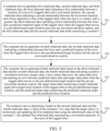
- FIG. 2 is a flowchart of a movement trajectory determining method according to an embodiment of the present disclosure.
- the method is performed by a computer device.
- the computer device is a legged robot or a control device.
- the method includes the following steps:
- the computer device creates first relational data, second relational data, and third relational data, the first relational data indicating a first relationship between a torso location of a legged robot and movement duration, the second relational data indicating a second relationship between the movement duration and a force applied to a foot of the legged robot in contact with a ground, the third relational data indicating a third relationship between the force applied to the foot of the legged robot in contact with the ground and a predicted rotational angle of the legged robot when the legged robot moves to a pre-determined target location and a pre-set movement duration expires, and the first relational data and the second relational data both including a constant C.
- the legged robot may be a robot that moves by simulating a walking attitude of an animal or a human being.
- the legged robot is a multi-legged robot.
- the legged robot is a two-legged robot, a four-legged robot, or a six-legged robot.
- a foot of the legged robot is controlled to be lifted or lowered to implement walking of the legged robot.
- the first relational data represents a movement trajectory of a torso of the legged robot during movement.
- the created first relational data includes the constant C.
- a value of the constant C is not determined. Therefore, the constant C included in the first relational data is also an unknown number C.
- the value of the constant C no longer changes.
- the constant C represents the relationship between the torso location and the movement duration. Therefore, a torso location of the legged robot in a case that any movement duration elapses cannot be determined based on the created first relational data. In this case, the torso location of the legged robot can be represented only by the constant C with an undetermined value and the movement duration.
- the constant C is also a known number C.
- a torso location of the legged robot in a case that any movement duration elapses can be determined based on the first relational data including the constant C with the determined value.
- the second relational data represents the relationship between the movement duration and the force applied to the foot of the legged robot in contact with the ground.
- the legged robot may rely on contact between the foot and the ground to support the legged robot to implement standing or walking, and a force is applied to the foot of the legged robot when the foot of the legged robot is in contact with the ground. Therefore, the second relational data is created to indicate a force applied to the foot of the legged robot during movement.
- the created second relational data includes the constant C with an undetermined value. In a case that the value of the constant C is not determined, based on the second relational data, any movement duration and the constant C can be used to represent a force applied to the foot of the legged robot in contact with the ground after the movement duration elapses.
- the error between the target status data and the predicted status data may include a rotational angle error.
- the target rotational angle is a known value
- the rotational angle error between the target rotational angle and the predicted rotational angle can be determined based on the predicted rotational angle and the target rotational angle.
- the rotational angle error can be represented by the force applied to the foot of the legged robot in contact with the ground. Therefore, the created fourth relational data indicates the positive correlation between the target value J and the status data error, and can also indicate a relationship between the target value J and the force applied to the foot of the legged robot in contact with the ground.
- the target value J may be positively correlated with the status data error.
- a value of the target value J can indicate a value of the status data error.
- the minimum value of the target value J is determined as far as possible to make the status data error sufficiently small. This can ensure that the predicted status data is closest to the target status data, and further ensure that, in a case that the legged robot subsequently moves based on a determined movement trajectory, status data that the legged robot can have when moving to the target location is closest to the target status data.
- the second relational data indicates the relationship between the movement duration and the force applied to the foot of the legged robot in contact with the ground
- the second relational data includes the constant C with an undetermined value
- the fourth relational data indicates the relationship between the target value J and the force applied to the foot of the legged robot in contact with the ground, that is, the target value J is related to the constant C.
- the value of the constant C is also determined, that is, the constant C is also a known number C.
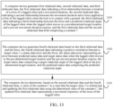
- the present disclosure provides a manner of determining a movement trajectory of a torso of a legged robot.
- a status data error between predicted status data and specified target status data is minimized by using status data including the rotational angle of the torso, and a value of a constant C in first relational data is determined, to ensure that the predicted status data is closest to the target status data.
- This further ensures that, in a case that the legged robot moves based on a determined movement trajectory, status data that the legged robot can have when moving to a target location is closest to the target status data, and ensures feasibility and accuracy of the determined movement trajectory.
- the computer device creates first relational data, second relational data, and third relational data, the first relational data indicating a first relationship between a torso location of a legged robot and movement duration, the second relational data indicating a second relationship between the movement duration and a force applied to a foot of the legged robot in contact with a ground, the third relational data indicating a third relationship between the force applied to the foot of the legged robot in contact with the ground and a predicted rotational angle of the legged robot when the legged robot moves to a pre-determined target location and a pre-set movement duration expires, and the first relational data and the second relational data both including a constant C.
- the time matrix represents the movement duration.
- the first constant matrix is any constant matrix, and a value of the first constant matrix is determined.
- the product of the constant C with an undetermined value and the time matrix may represent a torso location variation of the torso location of the legged robot relative to an initial torso location during movement.
- the legged robot moves from an initial location.
- the torso location of the legged robot changes with the movement duration.
- the second relational data is used to describe a dynamic constraint that the legged robot needs to meet during movement.
- the fifth relational data indicates a relationship between the force applied to the foot of the legged robot in contact with the ground and the predicted angular velocity when the legged robot moves to the pre-determined target location and the pre-set movement duration expires. Therefore, based on the fifth relational data, the force applied to the foot of the legged robot in contact with the ground can be used to represent the predicted angular velocity of the torso in a case that the legged robot moves to the target location.
- the error between the target status data and the predicted status data may include a rotational angle error and an angular velocity error. Because both the target rotational angle and the target angular velocity are known values, when the target rotational angle and the target angular velocity of the torso in a case that the legged robot moves to the target location are given, the rotational angle error between the target rotational angle and the predicted rotational angle can be determined based on the predicted rotational angle and the target rotational angle, and the angular velocity error between the target angular velocity and the predicted angular velocity can be determined based on the predicted angular velocity and the target angular velocity.
- Both the rotational angle error and the angular velocity error can be represented by the force applied to the foot of the legged robot in contact with the ground. Therefore, the created fourth relational data indicates the positive correlation between the target value J and the status data error, and can also indicate a relationship between the target value J and the force applied to the foot of the legged robot in contact with the ground.
- the target value J may be set to a sum of squares of the difference between the predicted rotational angle and the target rotational angle of the legged robot at the target location and the difference between the predicted angular velocity and the target angular velocity of the legged robot at the target location, so that the target value J has an extreme value, and a minimum value of the target value J can be determined subsequently.
- status data of the legged robot includes a rotational angle and an angular velocity of the torso of the legged robot.
- steps 302 and 303 do not need to be performed, and fourth relational data is created based on the third relational data in another manner, the fourth relational data indicating a positive correlation between a target value J and a status data error, the status data error representing an error between predicted status data and target status data when the legged robot moves to the pre-determined target location and the pre-set movement duration expires, the target status data including a target rotational angle of the legged robot at the target location, and the predicted status data including the predicted rotational angle of the legged robot at the target location.
- the target value J may be positively correlated with the status data error.
- a value of the target value J can indicate a value of the status data error. Therefore, the minimum value of the target value J is determined as far as possible to make the status data error sufficiently small. This can ensure that the predicted rotational angle and the predicted angular velocity of the torso in a case that the legged robot moves to the target location based on a determined movement trajectory are closest to the target rotational angle and the target angular velocity respectively, that is, the predicted status data is closest to the target status data. This further ensures that, in a case that the legged robot subsequently moves based on a determined movement trajectory, status data that the legged robot can have when moving to the target location is closest to the target status data
- the second relational data indicates the relationship between the movement duration and the force applied to the foot of the legged robot in contact with the ground
- the second relational data includes the constant C with an undetermined value
- the fourth relational data indicates the relationship between the target value J and the force applied to the foot of the legged robot in contact with the ground, that is, the target value J is related to the constant C.
- the value of the constant C is also determined, that is, the constant C is also a known number C.
- the updated first relational data can indicate a change of the torso location of the legged robot along with the movement duration.
- the updated first relational data represents the movement trajectory of the torso of the legged robot.
- a torso location of the legged robot in a case that any movement duration elapses can be determined based on the movement trajectory.
- a process of determining the value of the constant C in a case that the target value J is the minimum value includes: determining, based on the fourth relational data, a value of the force applied to the foot of the legged robot in contact with the ground in a case that the target value J is the minimum value; and determining the value of the constant C based on the value of the force applied to the foot of the legged robot in contact with the ground, the target movement duration, and the second relational data, and updating the first relational data using the determined value of the constant C
- the fourth relational data may indicate the relationship between the target value J and the force applied to the foot of the legged robot in contact with the ground. Therefore, the value of the force applied to the foot of the legged robot in contact with the ground in a case that the target value J is the minimum value can be determined based on the fourth relational data. Then the value of the constant C can be determined by substituting the force with the determined value into the second relational data. Then, when the constant C with the determined value is substituted into the first relational data, the first relational data is updated using the determined value of the constant C.
- a value of a force applied to each foot of the legged robot in contact with the ground in a case that the target value J is the minimum value may be determined based on the fourth relational data.
- a status of contact between each foot of the legged robot and the ground can be learned by determining the value of the force applied to each foot of the legged robot in contact with the ground.
- the present disclosure provides a manner of determining a movement trajectory of a torso of a legged robot.
- a status data error between predicted status data and specified target status data is minimized by using status data including the rotational angle of the torso, and a value of a constant C in first relational data is determined, to ensure that the predicted status data is closest to the target status data.
- This further ensures that, in a case that the legged robot moves based on a determined movement trajectory, status data that the legged robot can have when moving to a target location is closest to the target status data, and ensures feasibility and accuracy of the determined movement trajectory.
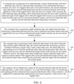
- FIG. 4 is a flowchart of a movement trajectory determining method according to an embodiment of the present disclosure. The method is performed by a computer device.
- the computer device is a legged robot or a control device. As shown in FIG. 4 , the method includes the following steps:
- the computer device creates first relational data, second relational data, and third relational data, the first relational data indicating a first relationship between a torso location of a legged robot and movement duration, the second relational data indicating a second relationship between the movement duration and a force applied to a foot of the legged robot in contact with a ground, the third relational data indicating a third relationship between the force applied to the foot of the legged robot in contact with the ground and a predicted rotational angle of the legged robot when the legged robot moves to a pre-determined target location and a pre-set movement duration expires, and the first relational data and the second relational data both including a constant C with an undetermined value.
- Step 401 is similar to step 301. Details are not described herein again.
- the computer device creates sixth relational data, the sixth relational data indicating a relationship between the force applied to the foot of the legged robot in contact with the ground and a predicted angular acceleration when the legged robot moves to the pre-determined target location and the pre-set movement duration expires.
- an angular acceleration of the legged robot may be an angular acceleration of the torso of the legged robot.
- the angular acceleration of the torso of the legged robot is affected by the force applied to the foot of the legged robot in contact with the ground.
- the angular acceleration of the torso of the legged robot is related to the force applied to the foot of the legged robot in contact with the ground. Therefore, the sixth relational data is generated to indicate impact of the force applied to the foot of the legged robot in contact with the ground on the angular acceleration of the torso of the legged robot when the legged robot moves to the pre-determined target location and the pre-set movement duration expires.
- the generating sixth relational data includes: setting the sixth relational data to be as follows: the predicted angular acceleration of the torso of the legged robot at the target location being equal to a sum of a fourth product and a fourth constant matrix, the fourth product being a product of a fourth coefficient matrix and a force matrix.
- the force matrix is a matrix including a force applied to at least one foot of the legged robot in contact with the ground.
- the fourth coefficient matrix represents a coefficient for the force matrix.
- the fourth constant matrix is any constant matrix, and a parameter value in the fourth constant matrix is determined.
- both the fourth coefficient matrix and the fourth constant matrix may be determined based on the target movement duration.
- both the fourth coefficient matrix with an undetermined value and the fourth constant matrix with an undetermined value may be matrices including the movement duration. In a case that the target movement duration is given, values of the fourth coefficient matrix and the fourth constant matrix are determined.
- the computer device creates fourth relational data based on the third relational data and the sixth relational data, the fourth relational data indicating a positive correlation between a target value J and a status data error, the status data error representing an error between predicted status data and target status data when the legged robot moves to the pre-determined target location and the pre-set movement duration expires, the target status data including a target rotational angle and a target angular acceleration of the legged robot at the target location, and the predicted status data including the predicted rotational angle and the predicted angular acceleration.
- the target status data may include an expected target rotational angle and an expected target angular acceleration of the torso in a case that the legged robot moves to the target location, and both the target rotational angle and the target angular acceleration are known values.
- the third relational data indicates a relationship between the force applied to the foot of the legged robot in contact with the ground and the predicted rotational angle when the legged robot moves to the pre-determined target location and the pre-set movement duration expires. Therefore, based on the third relational data, the force applied to the foot of the legged robot in contact with the ground can be used to represent the predicted rotational angle of the torso in a case that the legged robot moves to the target location.
- the sixth relational data indicates a relationship between the force applied to the foot of the legged robot in contact with the ground and the predicted angular acceleration when the legged robot moves to the pre-determined target location and the pre-set movement duration expires. Therefore, based on the sixth relational data, the force applied to the foot of the legged robot in contact with the ground can be used to represent the predicted angular acceleration of the torso in a case that the legged robot moves to the target location.
- the error between the target status data and the predicted status data may include a rotational angle error and an angular acceleration error. Because both the target rotational angle and the target angular acceleration are known values, when the target rotational angle and the target angular acceleration of the torso in a case that the legged robot moves to the target location are given, the rotational angle error between the target rotational angle and the predicted rotational angle can be determined based on the predicted rotational angle and the target rotational angle, and the angular acceleration error between the target angular acceleration and the predicted angular acceleration can be determined based on the predicted angular acceleration and the target angular acceleration.
- Both the rotational angle error and the angular acceleration error can be represented by the force applied to the foot of the legged robot in contact with the ground. Therefore, the created fourth relational data indicates the positive correlation between the target value J and the status data error, and can also indicate a relationship between the target value J and the force applied to the foot of the legged robot in contact with the ground.
- step 403 includes: setting the target value J in the fourth relational data to a sum of squares of a first difference and a third difference, the first difference being a difference between the predicted rotational angle and the target rotational angle of the legged robot at the target location, and the third difference being a difference between the predicted angular acceleration and the target angular acceleration of the legged robot at the target location.
- the target value J may be set to a sum of squares of the difference between the predicted rotational angle and the target rotational angle of the legged robot at the target location and the difference between the predicted angular acceleration and the target angular acceleration of the legged robot at the target location, so that the target value J has an extreme value, and a minimum value of the target value J can be determined subsequently.
- status data of the legged robot includes a rotational angle and an angular acceleration of the torso of the legged robot.
- steps 402 and 403 do not need to be performed, and fourth relational data is created based on the third relational data in another manner, the fourth relational data indicating a positive correlation between a target value J and a status data error, the status data error representing an error between predicted status data and target status data when the legged robot moves to the pre-determined target location and the pre-set movement duration expires, the target status data including a target rotational angle of the legged robot at the target location, and the predicted status data including the predicted rotational angle.
- the computer device determines, based on the second relational data and the fourth relational data, a value of the constant C in a case that the target value J is a minimum value, and updates the first relational data using the determined value of the constant C , the updated first relational data representing the movement trajectory of the torso of the legged robot.
- Step 404 is similar to step 304. Details are not described herein again.
- the present disclosure provides a manner of determining a movement trajectory of a torso of a legged robot.
- a status data error between predicted status data and specified target status data is minimized by using status data including the rotational angle of the torso, and a value of a constant C in first relational data is determined, to ensure that the predicted status data is closest to the target status data.
- This further ensures that, in a case that the legged robot moves based on a determined movement trajectory, status data that the legged robot can have when moving to a target location is closest to the target status data, and ensures feasibility and accuracy of the determined movement trajectory.
- FIG. 5 is a flowchart of a movement trajectory determining method according to an embodiment of the present disclosure. The method is performed by a computer device.
- the computer device is a legged robot or a control device. As shown in FIG. 5 , the method includes the following steps:
- the computer device creates first relational data, second relational data, and third relational data, the first relational data indicating a first relationship between a torso location of a legged robot and movement duration, the second relational data indicating a second relationship between the movement duration and a force applied to a foot of the legged robot in contact with a ground, the third relational data indicating a third relationship between the force applied to the foot of the legged robot in contact with the ground and a predicted rotational angle of the legged robot when the legged robot moves to a pre-determined target location and a pre-set movement duration expires, and the first relational data and the second relational data both including a constant C.
- Step 501 is similar to step 301. Details are not described herein again.
- the computer device creates seventh relational data, the seventh relational data indicating a relationship between the force applied to the foot of the legged robot in contact with the ground and a predicted torso location when the legged robot moves to the pre-determined target location and the pre-set movement duration expires.
- the predicted torso location of the legged robot may be a location of the torso of the legged robot.
- the torso location of the legged robot is affected by the force applied to the foot of the legged robot in contact with the ground, and the torso location of the legged robot is related to the force applied to the foot of the legged robot in contact with the ground. Therefore, the seventh relational data is generated to indicate impact of the force applied to the foot of the legged robot in contact with the ground on the torso location of the legged robot when the legged robot moves to the pre-determined target location and the pre-set movement duration expires.
- the generating seventh relational data includes: setting the seventh relational data to be as follows: the predicted torso location of the legged robot at the target location being equal to a sum of a fifth product and a fifth constant matrix, the fifth product being a product of a fifth coefficient matrix and a force matrix.
- the force matrix is a matrix including a force applied to at least one foot of the legged robot in contact with the ground.
- the fifth coefficient matrix represents a coefficient for the force matrix.
- the fifth constant matrix is any constant matrix, and a parameter value in the fifth constant matrix is determined.
- both the fifth coefficient matrix and the fifth constant matrix may be determined based on the target movement duration.
- both the fifth coefficient matrix with an undetermined value and the fifth constant matrix with an undetermined value may be matrices including the movement duration. In a case that the target movement duration is given, values of the fifth coefficient matrix and the fifth constant matrix are determined.
- the computer device creates fourth relational data based on the third relational data and the seventh relational data, the fourth relational data indicating a positive correlation between a target value J and a status data error, the status data error representing an error between predicted status data and target status data when the legged robot moves to the pre-determined target location and the pre-set movement duration expires, the target status data including a target rotational angle and a target torso location of the legged robot at the target location, and the predicted status data including the predicted rotational angle and the predicted torso location.
- the target status data may include an expected target rotational angle of the torso and an expected target torso location in a case that the legged robot moves to the target location, and both the target rotational angle and the target torso location are known values.
- the third relational data indicates a relationship between the force applied to the foot of the legged robot in contact with the ground and the predicted rotational angle when the legged robot moves to the pre-determined target location and the pre-set movement duration expires. Therefore, based on the third relational data, the force applied to the foot of the legged robot in contact with the ground can be used to represent the predicted rotational angle of the torso in a case that the legged robot moves to the target location.
- the seventh relational data indicates a relationship between the force applied to the foot of the legged robot in contact with the ground and the predicted torso location when the legged robot moves to the pre-determined target location and the pre-set movement duration expires. Therefore, based on the seventh relational data, the force applied to the foot of the legged robot in contact with the ground can be used to represent the predicted torso location of the torso in a case that the legged robot moves to the target location.
- the error between the target status data and the predicted status data may include a rotational angle error and a torso location error. Because both the target rotational angle and the target torso location are known values, when the target rotational angle of the torso and the target torso location in a case that the legged robot moves to the target location are given, the rotational angle error between the target rotational angle and the predicted rotational angle can be determined based on the predicted rotational angle and the target rotational angle, and the torso location error between the target torso location and the predicted torso location can be determined based on the predicted torso location and the target torso location.
- Both the rotational angle error and the torso location error can be represented by the force applied to the foot of the legged robot in contact with the ground. Therefore, the created fourth relational data indicates the positive correlation between the target value J and the status data error, and can also indicate a relationship between the target value J and the force applied to the foot of the legged robot in contact with the ground.
- step 503 includes: setting the target value J in the fourth relational data to a sum of squares of a first difference and a fourth difference, the first difference being a difference between the predicted rotational angle and the target rotational angle of the legged robot at the target location, and the fourth difference being a difference between the predicted torso location and the target torso location of the legged robot at the target location.
- the target value J may be set to a sum of squares of the difference between the predicted rotational angle and the target rotational angle of the legged robot at the target location and the difference between the predicted torso location and the target torso location of the legged robot at the target location, so that the target value J has an extreme value, and a minimum value of the target value J can be determined subsequently.
- status data of the legged robot includes a rotational angle and a torso location of the torso of the legged robot.
- steps 502 and 503 do not need to be performed, and fourth relational data is created based on the third relational data in another manner, the fourth relational data indicating a positive correlation between a target value J and a status data error, the status data error representing an error between predicted status data and target status data when the legged robot moves to the pre-determined target location and the pre-set movement duration expires, the target status data including a target rotational angle of the legged robot at the target location, and the predicted status data including the predicted rotational angle.
- the computer device determines, based on the second relational data and the fourth relational data, a value of the constant C in a case that the target value J is a minimum value, and updates the first relational data using the determined value of the constant C , the updated first relational data representing the movement trajectory of the torso of the legged robot.
- Step 504 is similar to step 304. Details are not described herein again.
- the present disclosure provides a manner of determining a movement trajectory of a torso of a legged robot.
- a status data error between predicted status data and specified target status data is minimized by using status data including the rotational angle of the torso, and a value of a constant C in first relational data is determined, to ensure that the predicted status data is closest to the target status data.
- This further ensures that, in a case that the legged robot moves based on a determined movement trajectory, status data that the legged robot can have when moving to a target location is closest to the target status data, and ensures feasibility and accuracy of the determined movement trajectory.
- FIG. 6 is a flowchart of a movement trajectory determining method according to an embodiment of the present disclosure. The method is performed by a computer device.
- the computer device is a legged robot or a control device. As shown in FIG. 6 , the method includes the following steps:
- the computer device creates first relational data, second relational data, and third relational data, the first relational data indicating a first relationship between a torso location of a legged robot and movement duration, the second relational data indicating a second relationship between the movement duration and a force applied to a foot of the legged robot in contact with a ground, the third relational data indicating a third relationship between the force applied to the foot of the legged robot in contact with the ground and a predicted rotational angle of the legged robot when the legged robot moves to a pre-determined target location and a pre-set movement duration expires, and the first relational data and the second relational data both including a constant C.
- Step 601 is similar to step 301. Details are not described herein again.
- the computer device creates eighth relational data, the eighth relational data indicating a relationship between the force applied to the foot of the legged robot in contact with the ground and a predicted movement speed when the legged robot moves to the pre-determined target location and the pre-set movement duration expires.
- the predicted movement speed of the legged robot may be a movement speed of the torso of the legged robot.
- the movement speed of the legged robot is affected by the force applied to the foot of the legged robot in contact with the ground, and the movement speed of the legged robot is related to the force applied to the foot of the legged robot in contact with the ground. Therefore, the eighth relational data is generated to indicate impact of the force applied to the foot of the legged robot in contact with the ground on the movement speed of the legged robot when the legged robot moves to the pre-determined target location and the pre-set movement duration expires.
- the generating eighth relational data includes: setting the eighth relational data to be as follows: the predicted movement speed of the torso of the legged robot at the target location being equal to a sum of a sixth product and a sixth constant matrix, the sixth product being a product of a sixth coefficient matrix and a force matrix.
- the force matrix is a matrix including a force applied to at least one foot of the legged robot in contact with the ground.
- the sixth coefficient matrix represents a coefficient for the force matrix.
- the sixth constant matrix is any constant matrix, and a parameter value in the sixth constant matrix is determined.
- both the sixth coefficient matrix and the sixth constant matrix may be determined based on the target movement duration.
- both the sixth coefficient matrix with an undetermined value and the sixth constant matrix with an undetermined value may be matrices including the movement duration. In a case that the target movement duration is given, values of the sixth coefficient matrix and the sixth constant matrix are determined.
- the computer device creates fourth relational data based on the third relational data and the eighth relational data, the fourth relational data indicating a positive correlation between a target value J and a status data error, the status data error representing an error between predicted status data and target status data when the legged robot moves to the pre-determined target location and the pre-set movement duration expires, the target status data including a target rotational angle and a target movement speed of the legged robot at the target location, and the predicted status data including the predicted rotational angle and the predicted movement speed.
- the target status data may include an expected target rotational angle and an expected target movement speed of the torso in a case that the legged robot moves to the target location, and both the target rotational angle and the target movement speed are known values.
- the third relational data indicates a relationship between the force applied to the foot of the legged robot in contact with the ground and the predicted rotational angle when the legged robot moves to the pre-determined target location and the pre-set movement duration expires. Therefore, based on the third relational data, the force applied to the foot of the legged robot in contact with the ground can be used to represent the predicted rotational angle of the torso in a case that the legged robot moves to the target location.
- the eighth relational data indicates a relationship between the force applied to the foot of the legged robot in contact with the ground and the predicted movement speed when the legged robot moves to the pre-determined target location and the pre-set movement duration expires. Therefore, based on the eighth relational data, the force applied to the foot of the legged robot in contact with the ground can be used to represent the predicted movement speed of the torso in a case that the legged robot moves to the target location.
- the error between the target status data and the predicted status data may include a rotational angle error and a movement speed error. Because both the target rotational angle and the target movement speed are known values, when the target rotational angle and the target movement speed of the torso in a case that the legged robot moves to the target location are given, the rotational angle error between the target rotational angle and the predicted rotational angle can be determined based on the predicted rotational angle and the target rotational angle, and the movement speed error between the target movement speed and the predicted movement speed can be determined based on the predicted movement speed and the target movement speed. Both the rotational angle error and the movement speed error can be represented by the force applied to the foot of the legged robot in contact with the ground. Therefore, the created fourth relational data indicates the positive correlation between the target value J and the status data error, and can also indicate a relationship between the target value J and the force applied to the foot of the legged robot in contact with the ground.
- step 603 includes: setting the target value J in the fourth relational data to a sum of squares of a first difference and a fifth difference, the first difference being a difference between the predicted rotational angle and the target rotational angle of the legged robot at the target location, and the fifth difference being a difference between the predicted movement speed and the target movement speed of the legged robot at the target location.
- the target value J may be set to a sum of squares of the difference between the predicted rotational angle and the target rotational angle of the legged robot at the target location and the difference between the predicted movement speed and the target movement speed of the legged robot at the target location, so that the target value J has an extreme value, and a minimum value of the target value J can be determined subsequently.
- status data of the legged robot includes a rotational angle and a movement speed of the torso of the legged robot.
- steps 602 and 603 do not need to be performed, and fourth relational data is created based on the third relational data in another manner, the fourth relational data indicating a positive correlation between a target value J and a status data error, the status data error representing an error between predicted status data and target status data when the legged robot moves to the pre-determined target location and the pre-set movement duration expires, the target status data including a target rotational angle of the legged robot at the target location, and the predicted status data including the predicted rotational angle.
- the computer device determines, based on the second relational data and the fourth relational data, a value of the constant C in a case that the target value J is a minimum value, and updates the first relational data using the determined value of the constant C , the updated first relational data representing the movement trajectory of the torso of the legged robot.
- Step 604 is similar to step 304. Details are not described herein again.
- the present disclosure provides a manner of determining a movement trajectory of a torso of a legged robot.
- a status data error between predicted status data and specified target status data is minimized by using status data including the rotational angle of the torso, and a value of a constant C in first relational data is determined, to ensure that the predicted status data is closest to the target status data.
- This further ensures that, in a case that the legged robot moves based on a determined movement trajectory, status data that the legged robot can have when moving to a target location is closest to the target status data, and ensures feasibility and accuracy of the determined movement trajectory.
- FIG. 7 is a flowchart of a movement trajectory determining method according to an embodiment of the present disclosure. The method is performed by a computer device.
- the computer device is a legged robot or a control device. As shown in FIG. 7 , the method includes the following steps:
- the computer device creates first relational data, second relational data, and third relational data, the first relational data indicating a first relationship between a torso location of a legged robot and movement duration, the second relational data indicating a second relationship between the movement duration and a force applied to a foot of the legged robot in contact with a ground, the third relational data indicating a third relationship between the force applied to the foot of the legged robot in contact with the ground and a predicted rotational angle of the legged robot when the legged robot moves to a pre-determined target location and a pre-set movement duration expires, and the first relational data and the second relational data both including a constant C.
- Step 701 is similar to step 301. Details are not described herein again.
- the computer device creates ninth relational data, the ninth relational data indicating a relationship between the force applied to the foot of the legged robot in contact with the ground and a predicted acceleration when the legged robot moves to the pre-determined target location and the pre-set movement duration expires.
- the predicted acceleration of the legged robot may be an acceleration of the torso of the legged robot.
- the acceleration of the legged robot is affected by the force applied to the foot of the legged robot in contact with the ground, and the acceleration of the legged robot is related to the force applied to the foot of the legged robot in contact with the ground. Therefore, the ninth relational data is generated to indicate impact of the force applied to the foot of the legged robot in contact with the ground on the acceleration of the legged robot when the legged robot moves to the pre-determined target location and the pre-set movement duration expires.
- the generating ninth relational data includes: setting the ninth relational data to be as follows: the predicted acceleration of the torso of the legged robot at the target location being equal to a sum of a seventh product and a seventh constant matrix, the seventh product being a product of a seventh coefficient matrix and a force matrix.
- the force matrix is a matrix including a force applied to at least one foot of the legged robot in contact with the ground.
- the seventh coefficient matrix represents a coefficient for the force matrix.
- the seventh constant matrix is any constant matrix, and a parameter value in the seventh constant matrix is determined.
- both the seventh coefficient matrix and the seventh constant matrix may be determined based on the target movement duration.
- both the seventh coefficient matrix with an undetermined value and the seventh constant matrix with an undetermined value may be matrices including the movement duration. In a case that the target movement duration is given, values of the seventh coefficient matrix and the seventh constant matrix are determined.
- the computer device creates fourth relational data based on the third relational data and the ninth relational data, the fourth relational data indicating a positive correlation between a target value J and a status data error, the status data error representing an error between predicted status data and target status data when the legged robot moves to the pre-determined target location and the pre-set movement duration expires, the target status data including a target rotational angle and a target acceleration of the legged robot at the target location, and the predicted status data including the predicted rotational angle and the predicted acceleration.
- the target status data includes an expected target rotational angle and an expected target acceleration of the torso in a case that the legged robot moves to the target location, and both the target rotational angle and the target acceleration are known values.
- the third relational data indicates a relationship between the force applied to the foot of the legged robot in contact with the ground and the predicted rotational angle when the legged robot moves to the pre-determined target location and the pre-set movement duration expires. Therefore, based on the third relational data, the force applied to the foot of the legged robot in contact with the ground can be used to represent the predicted rotational angle of the torso in a case that the legged robot moves to the target location.
- the ninth relational data indicates a relationship between the force applied to the foot of the legged robot in contact with the ground and the predicted acceleration when the legged robot moves to the pre-determined target location and the pre-set movement duration expires. Therefore, based on the ninth relational data, the force applied to the foot of the legged robot in contact with the ground can be used to represent the predicted acceleration of the torso in a case that the legged robot moves to the target location.
- the error between the target status data and the predicted status data may include a rotational angle error and an acceleration error. Because both the target rotational angle and the target acceleration are known values, when the target rotational angle and the target acceleration of the torso in a case that the legged robot moves to the target location are given, the rotational angle error between the target rotational angle and the predicted rotational angle can be determined based on the predicted rotational angle and the target rotational angle, and the acceleration error between the target acceleration and the predicted acceleration can be determined based on the predicted acceleration and the target acceleration. Both the rotational angle error and the acceleration error can be represented by the force applied to the foot of the legged robot in contact with the ground. Therefore, the created fourth relational data indicates the positive correlation between the target value J and the status data error, and can also indicate a relationship between the target value J and the force applied to the foot of the legged robot in contact with the ground.
- step 703 includes: setting the target value J in the fourth relational data to a sum of squares of a first difference and a sixth difference, the first difference being a difference between the predicted rotational angle and the target rotational angle of the legged robot at the target location, and the sixth difference being a difference between the predicted acceleration and the target acceleration of the legged robot at the target location.
- the target value J may be set to a sum of squares of the difference between the predicted rotational angle and the target rotational angle of the legged robot at the target location and the difference between the predicted acceleration and the target acceleration of the legged robot at the target location, so that the target value J has an extreme value, and a minimum value of the target value J can be determined subsequently.
- status data of the legged robot includes a rotational angle and an acceleration of the torso of the legged robot.
- steps 702 and 703 do not need to be performed, and fourth relational data is created based on the third relational data in another manner, the fourth relational data indicating a positive correlation between a target value J and a status data error, the status data error representing an error between predicted status data and target status data when the legged robot moves to the pre-determined target location and the pre-set movement duration expires, the target status data including a target rotational angle of the legged robot at the target location, and the predicted status data including the predicted rotational angle.
- the computer device determines, based on the second relational data and the fourth relational data, a value of the constant C in a case that the target value J is a minimum value, and updates the first relational data using the determined value of the constant C , the updated first relational data representing the movement trajectory of the torso of the legged robot.
- Step 704 is similar to step 304. Details are not described herein again.
- the present disclosure provides a manner of determining a movement trajectory of a torso of a legged robot.
- a status data error between predicted status data and specified target status data is minimized by using status data including the rotational angle of the torso, and a value of a constant C in first relational data is determined, to ensure that the predicted status data is closest to the target status data.
- This further ensures that, in a case that the legged robot moves based on a determined movement trajectory, status data that the legged robot can have when moving to a target location is closest to the target status data, and ensures feasibility and accuracy of the determined movement trajectory.
- FIG. 8 is a flowchart of a movement trajectory determining method according to an embodiment of the present disclosure. The method is performed by a computer device.
- the computer device is a legged robot or a control device. As shown in FIG. 8 , the method includes the following steps:
- the computer device creates first relational data, second relational data, and third relational data, the first relational data indicating a first relationship between a torso location of a legged robot and movement duration, the second relational data indicating a second relationship between the movement duration and a force applied to a foot of the legged robot in contact with a ground, the third relational data indicating a third relationship between the force applied to the foot of the legged robot in contact with the ground and a predicted rotational angle of the legged robot when the legged robot moves to a pre-determined target location and a pre-set movement duration expires, and the first relational data and the second relational data both including a constant C.
- Step 801 is similar to step 301. Details are not described herein again.
- the computer device selects a plurality of sampling time points within the target movement duration.
- the target movement duration may be any duration.
- the target movement duration is a time period with an initial time point as a starting point and an end time point as an ending point.
- the legged robot is at an initial location.
- the legged robot is at the target location.
- the sampling time point is a time point between the initial time point corresponding to the initial location and the end time point corresponding to the target location.
- the plurality of sampling time points include two or more sampling time points. Interval duration between any two adjacent sampling time points may or may not be equal.
- the target movement duration is 60 seconds
- the initial time point corresponding to the initial location is 0 seconds
- the end time point corresponding to the target location is 60 seconds
- five sampling time points are selected within the target movement duration.
- a first sampling time point is 10 seconds
- a second sampling time point is 20 seconds
- a third sampling time point is 30 seconds
- a fourth sampling time point is 40 seconds
- a fifth sampling time point is 50 seconds.
- a first sampling time point is 5 seconds
- a second sampling time point is 20 seconds
- a third sampling time point is 25 seconds
- a fourth sampling time point is 40 seconds
- a fifth sampling time point is 55 seconds.
- step 802 includes: dividing the target movement duration into a plurality of time periods, using an end time point of each time period as a sampling time point, and using a start time point of the first time period as a sampling time point.
- the plurality of time periods obtained may or may not be equal.
- the computer device creates tenth relational data for each sampling time point, the tenth relational data indicating a relationship between the force applied to the legged robot in contact with the ground and a rotational angle of the legged robot after movement duration between the sampling time point and an initial time point expires.
- the rotational angle of the legged robot is affected by the force applied to the foot of the legged robot in contact with the ground. Therefore, for movement duration for each sampling time point, a rotational angle of a torso of the legged robot in a case that the movement duration elapses is related to the force applied to the foot of the legged robot in contact with the ground. Therefore, the tenth relational data is created to indicate impact of the force applied to the foot of the legged robot in contact with the ground on the rotational angle of the legged robot in a case that the movement duration for each sampling time point elapses.
- the generating tenth relational data includes: setting the tenth relational data for each sampling time point to be as follows: the rotational angle being equal to a sum of an eighth product and an eighth constant matrix, the eighth product being a product of an eighth coefficient matrix and a force matrix.
- the force matrix is a matrix including a force applied to at least one foot of the legged robot in contact with the ground.
- the eighth coefficient matrix represents a coefficient for the force matrix.
- the eighth constant matrix is any constant matrix, and a parameter value in the eighth constant matrix is determined.
- both the eighth coefficient matrix and the eighth constant matrix in the tenth relational data for each sampling time point may be determined based on the movement duration for the sampling time point.
- both the eighth coefficient matrix with an undetermined value and the eighth constant matrix with an undetermined value may be matrices including movement duration. In a case that the movement duration for the sampling time point is given, values of the eighth coefficient matrix and the eighth constant matrix are determined.
- the computer device creates fourth relational data based on the third relational data and the tenth relational data, the fourth relational data indicating a positive correlation between a target value J and a status data error and rotational angles at the plurality of sampling time points, the status data error representing an error between predicted status data and target status data when the legged robot moves to the pre-determined target location and the pre-set movement duration expires, the target status data including a target rotational angle of the legged robot at the target location, and the predicted status data including the predicted rotational angle.
- the tenth relational data for each sampling time point may indicate a relationship between the force applied to the foot of the legged robot in contact with the ground and a rotational angle of the legged robot in a case that movement duration for the sampling time point elapses. Therefore, based on the tenth relational data for each sampling time point, the force applied to the foot of the legged robot in contact with the ground can be used to represent the rotational angle of the legged robot in a case that the movement duration for each sampling time point elapses.
- the target status data includes an expected target rotational angle of the torso in a case that the legged robot moves to the target location, and the target rotational angle is a known value.
- the third relational data indicates a relationship between the force applied to the foot of the legged robot in contact with the ground and the predicted rotational angle when the legged robot moves to the pre-determined target location and the pre-set movement duration expires. Therefore, based on the third relational data, the force applied to the foot of the legged robot in contact with the ground can be used to represent the predicted rotational angle of the torso in a case that the legged robot moves to the target location.
- the error between the target status data and the predicted status data may include a rotational angle error.
- the target rotational angle is a known value
- the rotational angle error between the target rotational angle and the predicted rotational angle can be determined based on the predicted rotational angle and the target rotational angle.
- the rotational angle error can be represented by the force applied to the foot of the legged robot in contact with the ground.
- the rotational angles at the plurality of sampling time points can also be represented by the force applied to the foot of the legged robot in contact with the ground. Therefore, the created fourth relational data indicates a positive correlation between the target value J and the status data error, and can also indicate a relationship between the target value J and the force applied to the foot of the legged robot in contact with the ground.
- step 804 includes: setting the target value J in the fourth relational data to a sum of a first value and a second value.
- the first value is a square of a first difference.
- the first difference is a difference between the target rotational angle and the predicted rotational angle.
- the second value is a weighted sum of squares of a plurality of rotational angle differences.
- the plurality of rotational angle differences include a difference between every two adjacent rotational angles in the rotational angles at the plurality of sampling time points.
- the target value J may be set to a sum of a square of the difference between the predicted rotational angle and the target rotational angle of the legged robot at the target location and the weighted sum of squares of the plurality of rotational angle differences, so that the target value J has an extreme value, and a minimum value of the target value J can be determined subsequently.
- a change of the rotational angle of the legged robot during movement is considered, to ensure feasibility of a subsequently determined movement trajectory.
- the fourth relational data may be generated by using the rotational angles at the plurality of sampling time points selected within the target movement duration.
- steps 802 to 804 do not need to be performed, and fourth relational data is created based on the third relational data in another manner, the fourth relational data indicating a positive correlation between a target value J and a status data error, the status data error representing an error between predicted status data and target status data when the legged robot moves to the pre-determined target location and the pre-set movement duration expires, the target status data including a target rotational angle of the legged robot at the target location, and the predicted status data including the predicted rotational angle.
- the computer device determines, based on the second relational data and the fourth relational data, a value of the constant C in a case that the target value J is a minimum value, and updates the first relational data using the determined value of the constant C , the updated first relational data representing the movement trajectory of the torso of the legged robot.
- Step 805 is similar to step 304. Details are not described herein again.
- the present disclosure provides a manner of determining a movement trajectory of a torso of a legged robot.
- a status data error between predicted status data and specified target status data is minimized by using status data including the rotational angle of the torso, and a value of a constant C in first relational data is determined, to ensure that the predicted status data is closest to the target status data.
- This further ensures that, in a case that the legged robot moves based on a determined movement trajectory, status data that the legged robot can have when moving to a target location is closest to the target status data, and ensures feasibility and accuracy of the determined movement trajectory.
- FIG. 9 is a flowchart of a movement trajectory determining method according to an embodiment of the present disclosure. The method is performed by a computer device.
- the computer device is a legged robot or a control device. As shown in FIG. 9 , the method includes the following steps:
- the computer device creates first relational data, second relational data, and third relational data, the first relational data indicating a first relationship between a torso location of a legged robot and movement duration, the second relational data indicating a second relationship between the movement duration and a force applied to a foot of the legged robot in contact with a ground, the third relational data indicating a third relationship between the force applied to the foot of the legged robot in contact with the ground and a predicted rotational angle of the legged robot when the legged robot moves to a pre-determined target location and a pre-set movement duration expires, and the first relational data and the second relational data both including a constant C.
- Step 901 is similar to step 301. Details are not described herein again.
- the computer device selects a plurality of sampling time points within the target movement duration.
- Step 902 is similar to step 802. Details are not described herein again.
- the computer device creates eleventh relational data for each sampling time point, the eleventh relational data indicating a relationship between the force applied to the legged robot in contact with the ground and a predicted torso location of the legged robot after movement duration between the sampling time point and an initial time point elapses.
- the torso location of the legged robot is affected by the force applied to the foot of the legged robot in contact with the ground. Therefore, for movement duration for each sampling time point, a torso location of the legged robot in a case that the movement duration elapses is related to the force applied to the foot of the legged robot in contact with the ground. Therefore, the eleventh relational data is created to indicate impact of the force applied to the foot of the legged robot in contact with the ground on the torso location of the legged robot in a case that the movement duration for each sampling time point elapses.
- the generating eleventh relational data includes: setting the eleventh relational data for each sampling time point to be as follows: the torso location being equal to a sum of a ninth product and a ninth constant matrix, the ninth product being a product of a ninth coefficient matrix and a force matrix.
- the force matrix is a matrix including a force applied to at least one foot of the legged robot in contact with the ground.
- the ninth coefficient matrix represents a coefficient for the force matrix.
- the ninth constant matrix is any constant matrix, and a parameter value in the ninth constant matrix is determined.
- both the ninth coefficient matrix and the ninth constant matrix in the eleventh relational data for each sampling time point may be determined based on the movement duration for the sampling time point.
- both the ninth coefficient matrix with an undetermined value and the ninth constant matrix with an undetermined value may be matrices including movement duration. In a case that the movement duration for the sampling time point is given, values of the ninth coefficient matrix and the ninth constant matrix are determined.
- the computer device creates fourth relational data based on the third relational data and the eleventh relational data, the fourth relational data indicating a positive correlation between a target value J and a status data error and a predicted torso location at each sampling time point, the status data error representing an error between predicted status data and target status data when the legged robot moves to the pre-determined target location and the pre-set movement duration expires, the target status data including a target rotational angle of the legged robot at the target location, and the predicted status data including the predicted rotational angle.
- the eleventh relational data for each sampling time point may indicate a relationship between the force applied to the foot of the legged robot in contact with the ground and a predicted torso location of the legged robot in a case that movement duration for the sampling time point elapses. Therefore, based on the eleventh relational data for each sampling time point, the force applied to the foot of the legged robot in contact with the ground can be used to represent the predicted torso location of the legged robot in a case that the movement duration for each sampling time point elapses.
- the target status data includes an expected target rotational angle of the torso in a case that the legged robot moves to the target location, and the target rotational angle is a known value.
- the third relational data indicates a relationship between the force applied to the foot of the legged robot in contact with the ground and the predicted rotational angle in a case that the legged robot moves to the pre-determined target location and the pre-set movement duration expires. Therefore, based on the third relational data, the force applied to the foot of the legged robot in contact with the ground can be used to represent the predicted rotational angle of the torso in a case that the legged robot moves to the target location.
- the error between the target status data and the predicted status data may include a rotational angle error.
- the target rotational angle is a known value
- the rotational angle error between the target rotational angle and the predicted rotational angle can be determined based on the predicted rotational angle and the target rotational angle.
- the rotational angle error can be represented by the force applied to the foot of the legged robot in contact with the ground.
- Predicted torso locations at the plurality of sampling time points can also be represented by the force applied to the foot of the legged robot in contact with the ground. Therefore, the created fourth relational data indicates a positive correlation between the target value J and the status data error, and can also indicate a relationship between the target value J and the force applied to the foot of the legged robot in contact with the ground.
- step 904 includes: setting the target value J in the fourth relational data to a sum of a first value and a third value.
- the first value is a square of a first difference.
- the first difference is a difference between the target rotational angle and the predicted rotational angle.
- the third value is a weighted sum of squares of a plurality of distances.
- the plurality of distances include a difference between every two adjacent predicted torso locations in the predicted torso locations at the plurality of sampling time points.
- the target value J may be set to a sum of a square of the difference between the predicted rotational angle and the target rotational angle of the legged robot at the target location and the weighted sum of squares of the plurality of distances, so that the target value J has an extreme value, and a minimum value of the target value J can be determined subsequently.
- a change of the torso location of the legged robot during movement is considered, to ensure feasibility of a subsequently determined movement trajectory.
- the fourth relational data may be generated by using the predicted torso locations at the plurality of sampling time points selected within the target movement duration.
- steps 902 to 904 do not need to be performed, and fourth relational data is created based on the third relational data in another manner, the fourth relational data indicating a positive correlation between a target value J and a status data error, the status data error representing an error between predicted status data and target status data when the legged robot moves to the pre-determined target location and the pre-set movement duration expires, the target status data including a target rotational angle of the legged robot at the target location, and the predicted status data including the predicted rotational angle.
- the computer device determines, based on the second relational data and the fourth relational data, a value of the constant C in a case that the target value J is a minimum value, and updates the first relational data using the determined value of the constant C , the updated first relational data representing the movement trajectory of the torso of the legged robot.
- Step 905 is similar to step 304. Details are not described herein again.
- the present disclosure provides a manner of determining a movement trajectory of a torso of a legged robot.
- a status data error between predicted status data and specified target status data is minimized by using status data including the rotational angle of the torso, and a value of a constant C in first relational data is determined, to ensure that the predicted status data is closest to the target status data.
- This further ensures that, in a case that the legged robot moves based on a determined movement trajectory, status data that the legged robot can have when moving to a target location is closest to the target status data, and ensures feasibility and accuracy of the determined movement trajectory.
- a change of the torso location of the legged robot during movement is considered, to ensure feasibility of a determined movement trajectory.
- FIG. 10 is a flowchart of a movement trajectory determining method according to an embodiment of the present disclosure.
- the method is performed by a computer device.
- the computer device is a legged robot or a control device.
- the method includes the following steps:
- the computer device creates first relational data, second relational data, and third relational data, the first relational data indicating a first relationship between a torso location of a legged robot and movement duration, the second relational data indicating a second relationship between the movement duration and a force applied to a foot of the legged robot in contact with a ground, the third relational data indicating a third relationship between the force applied to the foot of the legged robot in contact with the ground and a predicted rotational angle of the legged robot when the legged robot moves to a pre-determined target location and a pre-set movement duration expires, and the first relational data and the second relational data both including a constant C .
- Step 1001 is similar to step 301. Details are not described herein again.
- the computer device creates fourth relational data based on the third relational data, the fourth relational data indicating a positive correlation between a target value J and a status data error, the status data error representing an error between predicted status data and target status data when the legged robot moves to the pre-determined target location and the pre-set movement duration expires, the target status data including a target rotational angle of the legged robot at the target location, and the predicted status data including the predicted rotational angle.
- Step 1002 is similar to step 202. Details are not described herein again.
- the computer device creates a friction constraint, the friction constraint indicating a friction constraint met by the force applied to the foot of the legged robot in contact with the ground.
- the friction constraint is created to limit a status of contact between the foot and the ground during movement of the legged robot. This avoids relative sliding when the foot of the legged robot gets in contact with the ground during movement, and ensures that the legged robot can move properly.
- the computer device determines, based on the second relational data and the fourth relational data, a value of the constant C in a case that the target value J is a minimum value, and updates the first relational data using the determined value of the constant C , the updated first relational data representing the movement trajectory of the torso of the legged robot.
- the target value J may be positively correlated with the status data error.
- a value of the target value J can indicate a value of the status data error. Therefore, the minimum value of the target value J is determined as far as possible to make the status data error sufficiently small, and the force applied to the foot of the legged robot in contact with the ground is enabled to meet the friction constraint. This can ensure that the predicted status data is closest to the target status data, and further ensure that, in a case that the legged robot subsequently moves based on a determined movement trajectory, status data that the legged robot can have when moving to the target location is closest to the target status data. This ensures accuracy and feasibility of the determined movement trajectory.
- the present disclosure provides a manner of determining a movement trajectory of a torso of a legged robot.
- a status data error between predicted status data and specified target status data is minimized by using status data including the rotational angle of the torso, and a value of a constant C in first relational data is determined, to ensure that the predicted status data is closest to the target status data.
- This further ensures that, in a case that the legged robot moves based on a determined movement trajectory, status data that the legged robot can have when moving to a target location is closest to the target status data, and ensures feasibility and accuracy of the determined movement trajectory.
- the created friction constraint is used to limit a status of contact between the foot of the legged robot and the ground, to avoid relative sliding when the foot of the legged robot gets in contact with the ground during movement, to ensure that the legged robot can move properly and ensure feasibility of a determined movement trajectory of the legged robot.
- FIG. 11 is a flowchart of a movement trajectory determining method according to an embodiment of the present disclosure. The method is performed by a computer device.
- the computer device is a legged robot or a control device. As shown in FIG. 11 , the method includes the following steps:
- the computer device creates first relational data, second relational data, and third relational data, the first relational data indicating a first relationship between a torso location of a legged robot and movement duration, the second relational data indicating a second relationship between the movement duration and a force applied to a foot of the legged robot in contact with a ground, the third relational data indicating a third relationship between the force applied to the foot of the legged robot in contact with the ground and a predicted rotational angle of the legged robot when the legged robot moves to a pre-determined target location and a pre-set movement duration expires, and the first relational data and the second relational data both including a constant C with an undetermined value.
- Step 1101 is similar to step 301. Details are not described herein again.
- the computer device creates fourth relational data based on the third relational data, the fourth relational data indicating a positive correlation between a target value J and a status data error, the status data error representing an error between predicted status data and target status data when the legged robot moves to the pre-determined target location and the pre-set movement duration expires, the target status data including a target rotational angle of the legged robot at the target location, and the predicted status data including the predicted rotational angle.
- Step 1102 is similar to step 202. Details are not described herein again.
- the computer device creates a spatial constraint on the foot of the legged robot, the spatial constraint indicating a spatial range within which the foot of the legged robot is capable of moving, and the spatial constraint including a constant C with an undetermined value.
- a polyhedron 1201 in FIG. 12 is a spatial range within which a foot 1202 of a legged robot is capable of moving, the spatial range includes a plurality of spatial points, and the plurality of spatial points are spatial points that the foot 1201 is capable of reaching.
- the computer device determines, based on the second relational data and the fourth relational data, a value of the constant C in a case that the target value J is a minimum value, and updates the first relational data using the determined value of the constant C , the updated first relational data representing the movement trajectory of the torso of the legged robot.
- the target value J may be positively correlated with the status data error.
- a value of the target value J can indicate a value of the status data error. Therefore, the minimum value of the target value is determined as far as possible to make the status data error sufficiently small, and the foot of the legged robot is enabled to meet the spatial constraint. This can ensure that the predicted status data is closest to the target status data, and further ensure that, in a case that the legged robot subsequently moves based on a determined movement trajectory, status data that the legged robot can have when moving to the target location is closest to the target status data, and the foot of the legged robot is always within the spatial range within which the foot is capable of moving. This further ensures accuracy and feasibility of the determined movement trajectory.
- the present disclosure provides a manner of determining a movement trajectory of a torso of a legged robot.
- a status data error between predicted status data and specified target status data is minimized by using status data including the rotational angle of the torso, and a value of a constant C in first relational data is determined, to ensure that the predicted status data is closest to the target status data.
- This further ensures that, in a case that the legged robot moves based on a determined movement trajectory, status data that the legged robot can have when moving to a target location is closest to the target status data, and ensures feasibility and accuracy of the determined movement trajectory.
- the spatial constraint is used to indicate the spatial range within which the foot of the legged robot is capable of moving
- the spatial constraint is used to limit movement of the foot of the legged robot only within the spatial range within which the foot is capable of moving, to prevent the foot of the legged robot from moving beyond the spatial range within which the foot is capable of moving during movement based on a determined movement trajectory. This further ensures feasibility of the movement trajectory.
- FIG. 13 is a flowchart of a movement trajectory determining method according to an embodiment of the present disclosure.
- the method is performed by a computer device.
- the computer device is a legged robot or a control device.
- the method includes the following steps:
- the computer device creates first relational data, second relational data, and third relational data, the first relational data indicating a first relationship between a torso location of a legged robot and movement duration, the second relational data indicating a second relationship between the movement duration and a force applied to a foot of the legged robot in contact with a ground, the third relational data indicating a third relationship between the force applied to the foot of the legged robot in contact with the ground and a predicted rotational angle of the legged robot when the legged robot moves to a pre-determined target location and a pre-set movement duration expires, and the first relational data and the second relational data both including a constant C .
- Step 1301 is similar to step 301. Details are not described herein again.
- the computer device creates fourth relational data based on the third relational data and the force applied to the foot of the legged robot in contact with the ground, the fourth relational data indicating a positive correlation between a target value J and a status data error and the force applied to the foot of the legged robot in contact with the ground, the status data error representing an error between predicted status data and target status data when the legged robot moves to the pre-determined target location and the pre-set movement duration expires, the target status data including a target rotational angle of the legged robot at the target location, and the predicted status data including the predicted rotational angle.
- the force applied to the foot of the legged robot is considered, to ensure that the force applied to the legged robot conforms to a force applied to the legged robot during real movement, to ensure feasibility of a subsequently determined movement trajectory.
- step 1302 includes: setting the target value J to a sum of a square of a first difference and a weighted sum of squares of forces applied to the foot of the legged robot.
- the target value J may be set to a sum of a square of a difference between the predicted rotational angle and the target rotational angle of the legged robot at the target location and the weighted sum of squares of the forces applied to the foot of the legged robot, so that the target value J has an extreme value, and a minimum value of the target value J can be determined subsequently.
- the force applied to the foot of the legged robot during movement is considered, to ensure feasibility of a subsequently determined movement trajectory.
- the computer device determines, based on the second relational data and the fourth relational data, a value of the constant C in a case that the target value J is a minimum value, and updates the first relational data using the determined value of the constant C , the updated first relational data representing the movement trajectory of the torso of the legged robot.
- Step 1303 is similar to step 304. Details are not described herein again.
- the present disclosure provides a manner of determining a movement trajectory of a torso of a legged robot.
- a status data error between predicted status data and specified target status data is minimized by using status data including the rotational angle of the torso, and a value of a constant C in first relational data is determined, to ensure that the predicted status data is closest to the target status data.
- This further ensures that, in a case that the legged robot moves based on a determined movement trajectory, status data that the legged robot can have when moving to a target location is closest to the target status data, and ensures feasibility and accuracy of the determined movement trajectory.
- the force applied to the foot of the legged robot is considered, to ensure that the force applied to the legged robot conforms to a force applied to the legged robot during real movement, to ensure feasibility of a determined movement trajectory.
- FIG. 2 to FIG. 13 can be freely combined.
- the embodiments shown in FIG. 2 to FIG. 13 are combined.
- An embodiment of the present disclosure further provides a movement trajectory determining method.
- the method is performed by a computer device.
- the computer device is a legged robot or a control device.
- the method includes the following steps:
- the computer device creates first relational data, second relational data, and third relational data, the first relational data indicating a first relationship between a torso location of a legged robot and movement duration, the second relational data indicating a second relationship between the movement duration and a force applied to a foot of the legged robot in contact with a ground, the third relational data indicating a third relationship between the force applied to the foot of the legged robot in contact with the ground and a predicted rotational angle of the legged robot when the legged robot moves to a pre-determined target location and a pre-set movement duration expires, and the first relational data and the second relational data both including a constant C.
- the computer device creates fifth relational data, the fifth relational data indicating a relationship between the force applied to the foot of the legged robot in contact with the ground and a predicted angular velocity when the legged robot moves to the pre-determined target location and the pre-set movement duration expires.
- the computer device creates sixth relational data, the sixth relational data indicating a relationship between the force applied to the foot of the legged robot in contact with the ground and a predicted angular acceleration when the legged robot moves to the pre-determined target location and the pre-set movement duration expires.
- the computer device creates seventh relational data, the seventh relational data indicating a relationship between the force applied to the foot of the legged robot in contact with the ground and a predicted torso location when the legged robot moves to the pre-determined target location and the pre-set movement duration expires.
- the computer device creates eighth relational data, the eighth relational data indicating a relationship between the force applied to the foot of the legged robot in contact with the ground and a predicted movement speed when the legged robot moves to the pre-determined target location and the pre-set movement duration expires.
- the computer device creates ninth relational data, the ninth relational data indicating a relationship between the force applied to the foot of the legged robot in contact with the ground and a predicted acceleration when the legged robot moves to the pre-determined target location and the pre-set movement duration expires.
- the computer device selects a plurality of sampling time points within the target movement duration.
- the computer device creates tenth relational data for each sampling time point, the tenth relational data indicating a relationship between the force applied to the legged robot in contact with the ground and a rotational angle of the legged robot after movement duration between the sampling time point and an initial time point elapses.
- the computer device creates eleventh relational data for each sampling time point, the eleventh relational data indicating a relationship between the force applied to the legged robot in contact with the ground and a predicted torso location of the legged robot after movement duration between the sampling time point and an initial time point elapses.
- the computer device creates fourth relational data based on the third relational data, the fifth relational data, the sixth relational data, the seventh relational data, the eighth relational data, the ninth relational data, the tenth relational data, the eleventh relational data, and the force applied to the foot of the legged robot in contact with the ground, the fourth relational data indicating a positive correlation between a target value J and a status data error, the force applied to the foot of the legged robot in contact with the ground, the rotational angles at the plurality of sampling time points, and the predicted torso locations at the plurality of sampling time points, the status data error representing an error between predicted status data and target status data when the legged robot moves to the pre-determined target location and the pre-set movement duration expires, the target status data including a target rotational angle, a target angular velocity, a target angular acceleration, a target torso location, a target movement speed, and a target acceleration of the legged robot at the target location, and the predicted status data
- the computer device creates a friction constraint, the friction constraint indicating a friction constraint met by the force applied to the foot of the legged robot in contact with the ground.
- the computer device creates a spatial constraint on the foot of the legged robot, the spatial constraint indicating a spatial range within which the foot of the legged robot is capable of moving, and the spatial constraint including a constant C with an undetermined value.
- the computer device determines, based on the second relational data and the fourth relational data, a value of the constant C in a case that the target value J is a minimum value, and updates the first relational data using the determined value of the constant C , the updated first relational data representing a movement trajectory of a torso of the legged robot.
- the present disclosure provides a manner of determining a movement trajectory of a torso of a legged robot.
- a rotational angle, an angular velocity, an angular acceleration, a torso location, a movement speed, and an acceleration of the torso, and impact of a force applied to a foot of the legged robot on a movement trajectory are comprehensively considered, and movement of the legged robot is limited by a friction constraint and a spatial constraint, to ensure feasibility of a determined movement trajectory.
- the first relational data to the eleventh relational data in the embodiments shown in FIG. 2 to FIG. 14 can be stored in the legged robot in a form of a descriptive statement or a function.
- FIG. 2 to FIG. 14 are described by using an example of determining the movement trajectory of the torso of the legged robot.
- relational data between movement duration and a movement speed, an acceleration, a rotational angle, an angular velocity, and an angular acceleration of the legged robot can be further determined.
- a location and a posture of the legged robot during movement are determined, to control the legged robot to move based on a determined location and posture.
- twelfth relational data, thirteenth relational data, fourteenth relational data, fifteenth relational data, and sixteenth relational data are created, the twelfth relational data indicating a relationship between the movement speed of the legged robot and the movement duration, the thirteenth relational data indicating a relationship between the acceleration of the legged robot and the movement duration, the fourteenth relational data indicating a relationship between the rotational angle of the legged robot and the movement duration, the fifteenth relational data indicating a relationship between the angular velocity of the legged robot and the movement duration, and the sixteenth relational data indicating a relationship between the angular acceleration of the legged robot and the movement duration.
- All the twelfth relational data, the thirteenth relational data, the fourteenth relational data, the fifteenth relational data, and the sixteenth relational data include a constant C with an undetermined value. Therefore, after a value of the constant C is determined, twelfth relational data, thirteenth relational data, fourteenth relational data, fifteenth relational data, and sixteenth relational data with the determined value of the constant C are obtained, the twelfth relational data with the determined value of the constant C representing a speed trajectory of the legged robot, the thirteenth relational data with the determined value of the constant C representing an acceleration trajectory of the legged robot, the fourteenth relational data with the determined value of the constant C representing a rotational angle trajectory of the legged robot, the fifteenth relational data with the determined value of the constant C representing an angular velocity trajectory of the legged robot, and the sixteenth relational data with the determined value of the constant C representing an angular acceleration trajectory of the legged robot.
- the legged robot in a case that the movement trajectory, the speed trajectory, the acceleration trajectory, the rotational angle trajectory, the angular velocity trajectory, and the angular acceleration trajectory of the torso of the legged robot are determined, the legged robot may be controlled to move based on the movement trajectory, the speed trajectory, the acceleration trajectory, the rotational angle trajectory, the angular velocity trajectory, and the angular acceleration trajectory.
- an embodiment of the present disclosure further provides a block diagram of controlling, by a legged robot system, a legged robot to move.
- the legged robot system includes a visual perception subsystem 1501, a trajectory generation subsystem 1502, and a movement control subsystem 1503.
- the visual perception subsystem 1501 obtains a target location and a step order of the legged robot based on status data of the legged robot, and transmits the obtained target location and step order to the trajectory generation subsystem 1502.
- the visual perception system 1501 includes a camera.
- the legged robot photographs an environment in a movement direction of the legged robot by using the camera to obtain an environment image including the movement direction of the legged robot, performs feature extraction on the environment image to obtain a target location and a foothold location of the legged robot, and transmits the target location, the step order, and the foothold location to the trajectory generation subsystem 1502.
- the trajectory generation subsystem 1502 receives the target location and the step order of the legged robot that are transmitted by the visual perception subsystem 1501, determines a movement trajectory of a torso of the legged robot according to the embodiments shown in FIG. 2 to FIG. 14 , determines a joint torque for each joint of the legged robot based on the determined movement trajectory of the torso of the legged robot and the step order, and transmits the joint torque for each joint of the legged robot to the movement control subsystem 1503.
- the movement control subsystem 1503 receives the joint torque for each joint of the legged robot that is transmitted by the trajectory generation subsystem 1502, controls each joint to rotate based on the joint torque for each joint of the legged robot to drive the legged robot to move, and monitors status data of the legged robot in real time during a process of controlling the legged robot to move, to ensure that the legged robot can move stably.
- the first relational data to the eleventh relational data, the friction constraint, and the spatial constraint are included in the foregoing embodiments.
- the following embodiments describe in detail processes of generating the first relational data to the eleventh relational data, the friction constraint, and the spatial constraint.
- N represents a quantity of feet of the legged robot that are in contact with the ground, and N is an integer greater than 0.
- i represents a sequence number of a foot of the legged robot that is in contact with the ground, and i is a positive integer not greater than N.
- f i represents a force applied to an i th foot of the feet of the legged robot that are in contact with the ground in a world coordinate system.
- m represents mass of the legged robot.
- ⁇ represents a torso location of the legged robot in the world coordinate system.
- ⁇ p ⁇ represents an acceleration of the torso of the legged robot in the world coordinate system.
- g represents an acceleration of gravity.
- r i represents a contact location, on the ground, of the i th foot of the legged robot that is in contact with the ground in the world coordinate system.
- r ⁇ ⁇ represents a skew symmetric matrix for the contact location r i .
- p ⁇ represents a skew symmetric matrix for the torso location p.
- f i , p, g, r i and all belong to R 3 , and represents a set of real numbers in multidimensional space.
- ⁇ B represents an angular velocity of the torso of the legged robot in the coordinate system of the torso of the legged robot.
- the torso of the legged robot may be a base of the legged robot, and the coordinate system of the torso is a base coordinate system.
- ⁇ G represents the torque applied to the torso of the legged robot, and represents a rotational inertia of the torso of the legged robot in the coordinate system with the origin at the center of mass and with the same attitude as the world system.
- ⁇ G represents an angular velocity of the torso of the legged robot in the world coordinate system.
- ⁇ G represents a skew symmetric matrix for the angular velocity ⁇ G .
- ⁇ G represents an angular acceleration of the torso of the legged robot in the world coordinate system.
- ⁇ B represents the angular velocity of the torso of the legged robot in the coordinate system of the torso of the legged robot.
- ⁇ B represents an angular acceleration of the torso of the legged robot in the coordinate system of the torso of the legged robot.
- ⁇ represents the rotational inertia of the torso of the legged robot in the coordinate system of the torso of the legged robot.
- ⁇ represents a derivative of the attitude of the torso to time.
- R T is a transposed matrix of .
- the target movement duration is divided into k control periods. Duration of each control period is ⁇ T. A current time point is 0.
- p ⁇ k represents the acceleration of the legged robot.
- m represents the mass of the legged robot.
- N represents the quantity of feet of the legged robot that are in contact with the ground, and N is an integer greater than 0.
- i represents the sequence number of the foot of the legged robot that is in contact with the ground, and i is a positive integer not greater than N.
- f i,k represents a force applied to the i th foot of the feet of the legged robot that are in contact with the ground in the world coordinate system after the k control periods elapse.
- g represents the acceleration of gravity.
- ⁇ k represents the speed of the torso of the legged robot.
- ⁇ T represents the duration of the control period.
- j represents sequence numbers of the k control periods, and j is an integer not greater than k - 1.
- p ⁇ j represents an acceleration of the legged robot in a j th control period.
- ⁇ 0 represents an initial movement speed of the legged robot.
- p k represents the torso location of the legged robot.
- k represents a quantity of control periods for the legged robot.
- p 0 represents an initial location of the torso of the legged robot.
- ⁇ p k represents a torso location increment of the legged robot after the k control periods elapse.
- ⁇ k represents an angular velocity of the torso of the legged robot after a k th control period elapses.
- ⁇ j represents an angular acceleration of the torso of the legged robot within the j th control period.
- ⁇ 0 represents an initial angular velocity of the legged robot.
- ⁇ k represents a rotational angle of the torso of the legged robot within the k th control period.
- ⁇ 0 represents a rotational angle of the legged robot at an initial moment.
- ⁇ k represents an angular velocity increment of the torso of the legged robot after the k th control period elapses.
- ⁇ k represents a rotational angle increment of the torso of the legged robot after the k th control period elapses.
- the force f i applied to the foot of the legged robot in contact with the ground constitutes a force matrix F total.
- the torso location, the speed, and the angular velocity of the legged robot in the world coordinate system are all in a linear relationship with the force matrix F total . Therefore, after the k control periods elapse, the torso location, the speed, and the angular velocity of the legged robot in the world coordinate system meet the seventh relational data, the eighth relational data, and the ninth relational data.
- p k represents the torso location of the legged robot after the k control periods elapse, namely, the predicted torso location of the legged robot at the target location.
- a p,k represents the fifth coefficient matrix.
- F total represents the force matrix constituted by the force f i,k applied to the foot of the legged robot in contact with the ground.
- b p,k represents the fifth constant matrix.
- ⁇ k represents the movement speed of the torso of the legged robot after the k control periods elapse, namely, the predicted movement speed of the torso of the legged robot at the target location.
- a ⁇ , k represents the sixth coefficient matrix.
- b ⁇ ,k represents the sixth constant matrix.
- p ⁇ k represents the acceleration of the torso of the legged robot after the k control periods elapse, namely, the predicted acceleration of the torso of the legged robot at the target location.
- a p ⁇ , k represents the seventh coefficient matrix.
- b p ⁇ , k represents the seventh constant matrix.
- ⁇ T represents the duration of each control period.
- g represents the acceleration of gravity.
- ⁇ 0 represents the initial movement speed of the legged robot.
- p 0 represents the initial location of the torso of the legged robot.
- the attitude of the torso of the legged robot can meet the following relationship in the world coordinate system within the k th control period: R k ⁇ I + ⁇ ⁇ ⁇ k R 0
- R k represents an attitude of the torso of the legged robot in the world coordinate system within the k th control period.
- I is an identity matrix.
- ⁇ ⁇ k represents a skew symmetric matrix for the rotational angle increment ⁇ k of the torso of the legged robot after the k th control period elapses.
- R 0 represents an attitude of the torso of the legged robot in the world coordinate system at an initial time point.
- R 0 represents the attitude of the torso of the legged robot in the world coordinate system at the initial time point. represents the rotational inertia of the torso of the legged robot in the coordinate system of the torso.
- R 0 T represents a transposed matrix of the attitude R 0 .
- ⁇ k ⁇ k includes a quadratic term of ⁇ k .
- ⁇ k when being small, can be ignored.
- the formula (8) is substituted into the formula (3), and higher order terms related to ⁇ k and ⁇ k are ignored (a higher order is not less than a second order).
- ⁇ k represents the angular acceleration of the torso of the legged robot within the k th control period.
- ⁇ k represents the skew symmetric matrix for the rotational angle increment ⁇ k of the torso of the legged robot after the k th control period elapses.
- ⁇ 0 represents the initial angular velocity of the torso of the legged robot.
- ⁇ k represents the angular velocity increment of the torso of the legged robot after the k control periods elapse.
- ⁇ represents the rotational angle increment of the torso of the legged robot.
- ⁇ is a constant.
- ⁇ represents the angular acceleration of the torso of the legged robot.
- ⁇ is a constant.
- R x represents an attitude of the torso of the legged robot rotating around the X-axis in the coordinate system of the legged robot. represents the rotational inertia of the torso of the legged robot in the world coordinate system at the initial moment.
- the formula (9) may be simplified as follows: L ⁇ k ⁇ J 0 ⁇ ⁇ k + ⁇ ⁇ 0 J 0 ⁇ 0 + ⁇ ⁇ 0 J 0 ⁇ J 0 ⁇ 0 ⁇ ⁇ k
- ⁇ k represents a torque applied to the center of mass of the legged robot within the k th control period. represents the rotational inertia of the torso of the legged robot in the world coordinate system at the initial moment.
- ⁇ k represents the angular acceleration of the torso of the legged robot within the k th control period.
- ⁇ 0 represents a skew symmetric matrix for the initial angular velocity ⁇ 0 of the torso of the legged robot at the initial time point.
- ⁇ 0 represents the initial angular velocity of the torso of the legged robot at the initial time point.
- J 0 ⁇ 0 ⁇ represents a skew symmetric matrix for ⁇ 0 .
- ⁇ k represents the angular velocity increment of the torso of the legged robot after the k control periods elapse.
- ⁇ k represents the torque applied to the torso of the legged robot within the k th control period. represents the rotational inertia of the torso of the legged robot in the world coordinate system at the initial moment.
- ⁇ k represents the angular acceleration of the torso of the legged robot within the k th control period.
- ⁇ 0 represents the skew symmetric matrix for the initial angular velocity ⁇ 0 of the torso of the legged robot.
- J 0 ⁇ 0 ⁇ represents the skew symmetric matrix for ⁇ 0 .
- ⁇ k represents the angular velocity increment of the torso of the legged robot after the k control periods elapse.
- ⁇ k represents the rotational angle increment of the torso of the legged robot after the k control periods elapse.
- ⁇ k represents the torque applied to the torso of the legged robot within the k th control period. represents the rotational inertia of the torso of the legged robot in the world coordinate system at the initial moment.
- ⁇ k represents the angular acceleration of the torso of the legged robot within the k th control period.
- ⁇ 0 represents the skew symmetric matrix for the initial angular velocity ⁇ 0 of the torso of the legged robot.
- ⁇ k represents the angular velocity increment of the torso of the legged robot after the k control periods elapse.
- ⁇ k represents the rotational angle increment of the torso of the legged robot after the k control periods elapse.
- N represents the quantity of feet of the legged robot that are in contact with the ground, and N is an integer greater than 0.
- i represents the sequence number of the foot of the legged robot that is in contact with the ground, and i is a positive integer not greater than N.
- f i represents the force applied to the i th foot of the feet of the legged robot that are in contact with the ground in the world coordinate system.
- m represents the mass of the legged robot.
- p ⁇ represents the acceleration of the torso of the legged robot in the world coordinate system.
- g represents the acceleration of gravity.
- r i represents the contact location, on the ground, of the i th foot of the legged robot that is in contact with the ground in the world coordinate system.
- r ⁇ i represents the skew symmetric matrix for the contact location r i .
- p ⁇ represents the skew symmetric matrix for the torso location p.
- p ⁇ 0 represents a skew symmetric matrix for a torso location p 0 of the legged robot in the world coordinate system. represents the torque applied to the torso of the legged robot.
- N represents the quantity of feet of the legged robot that are in contact with the ground, and N is an integer greater than 0.
- i represents the sequence number of the foot of the legged robot that is in contact with the ground, and i is a positive integer not greater than N.
- f i,k represents the force applied to the i th foot of the feet of the legged robot that are in contact with the ground in the world coordinate system within the k th control period.
- m represents the mass of the legged robot.
- ⁇ p k represents the torso location increment of the legged robot after the k control periods elapse.
- g represents the acceleration of gravity.
- ⁇ represents a skew symmetric matrix for the acceleration of gravity g.
- r i,k represents a contact location, on the ground, of the i th foot of the legged robot that is in contact with the ground in the world coordinate system within the k th control period.
- r ⁇ i,k represents a skew symmetric matrix for the contact location r i,k .
- p ⁇ 0 represents the skew symmetric matrix for the torso location p 0 of the legged robot in the world coordinate system.
- ⁇ k represents the angular acceleration of the torso of the legged robot within the k th control period.
- ⁇ 0 represents the skew symmetric matrix for the initial angular velocity ⁇ 0 of the torso of the legged robot.
- ⁇ k represents the angular velocity increment of the torso of the legged robot after the k control periods elapse.
- ⁇ k represents the rotational angle increment of the torso of the legged robot after the k control periods elapse.
- N represents the quantity of feet of the legged robot that are in contact with the ground, and N is an integer greater than 0.
- i represents the sequence number of the foot of the legged robot that is in contact with the ground, and i is a positive integer not greater than N.
- f i,k represents the force applied to the i th foot of the feet of the legged robot that are in contact with the ground in the world coordinate system within the k th control period.
- m represents the mass of the legged robot.
- ⁇ p k represents the torso location increment of the legged robot after the k control periods elapse.
- g represents the acceleration of gravity.
- ⁇ represents the skew symmetric matrix for the acceleration of gravity g.
- r i,k represents the contact location, on the ground, of the i th foot of the legged robot that is in contact with the ground in the world coordinate system within the k th control period.
- r ⁇ i,k represents the skew symmetric matrix for the contact location r i,k .
- p ⁇ 0 represents the skew symmetric matrix for the torso location p 0 of the legged robot in the world coordinate system.
- ⁇ k represents the angular acceleration of the torso of the legged robot within the k th control period.
- ⁇ 0 represents the initial angular velocity of the torso of the legged robot.
- ⁇ 0 represents the skew symmetric matrix for the initial angular velocity ⁇ 0 of the torso of the legged robot.
- ⁇ k represents the angular velocity increment of the torso of the legged robot after the k control periods elapse.
- ⁇ k represents the rotational angle increment of the torso of the legged robot after the k control periods elapse.
- ⁇ T represents the duration of the control period.
- j represents the sequence numbers of the k control periods, and j is an integer not greater than k - 1.
- p ⁇ j represents the acceleration of the legged robot in the j th control period.
- ⁇ j represents the angular acceleration of the torso of the legged robot within the j th control period.
- ⁇ 0 represents an angular acceleration of the torso of the legged robot at the initial time point.
- J 0 ⁇ 1 is an inverse matrix of the rotational inertia .
- N represents the quantity of feet of the legged robot that are in contact with the ground, and N is an integer greater than 0.
- r i, 0 represents the sequence number of the foot of the legged robot that is in contact with the ground, and i is a positive integer not greater than N.
- r i, 0 represents a contact location, on the ground, of the i th foot of the legged robot that is in contact with the ground in the world coordinate system at the initial time point.
- r ⁇ i,0 represents a skew symmetric matrix for the contact location r i ,0 .
- p ⁇ 0 represents the skew symmetric matrix for the torso location p 0 of the legged robot in the world coordinate system.
- f i, 0 represents a force applied to the i th foot of the feet of the legged robot that are in contact with the ground in the world coordinate system at the initial time point.
- ⁇ 0 represents the initial angular velocity of the torso of the legged robot.
- ⁇ 0 represents the skew symmetric matrix for the initial angular velocity ⁇ 0 of the torso of the legged robot. Therefore, ⁇ 0 is in a linear relationship with the column vector F total .
- the angular acceleration ⁇ k of the torso of the legged robot within the k th control period is in a linear relationship with the force matrix F tot ⁇ l .
- the rotational angle, the angular velocity, and the acceleration of the torso of the legged robot in the world coordinate system are in a linear relationship with the force matrix F total . Therefore, after the k control periods elapse, the torso location, the speed, and the angular velocity of the legged robot in the world coordinate system meet the third relational data, the fifth relational data, and the sixth relational data.
- ⁇ k represents the rotational angle of the torso of the legged robot after the k control periods elapse, namely, the predicted rotational angle of the legged robot when the legged robot moves to the pre-determined target location and the pre-set movement duration expires.
- a ⁇ ,k represents the second coefficient matrix.
- F total represents the force matrix constituted by the force f i,k applied to the foot of the legged robot in contact with the ground.
- b ⁇ ,k represents the second constant matrix.
- ⁇ k represents the angular velocity of the torso of the legged robot after the k control periods elapse, namely, the predicted angular velocity of the torso of the legged robot in a case that the legged robot moves to the target location.
- a ⁇ ,k represents the third coefficient matrix.
- b ⁇ ,k represents the third constant matrix.
- ⁇ k represents the angular acceleration of the torso of the legged robot after the k control periods elapse, namely, the predicted angular acceleration of the torso of the legged robot at the target location.
- a ⁇ ,k represents the fourth coefficient matrix.
- b ⁇ ,k represents the fourth constant matrix.
- p ⁇ k represents an acceleration of the torso of the legged robot within the k th control period.
- T p ⁇ k represents a time matrix within the k th control period, where T p ⁇ k is a constant.
- c p ⁇ represents a first constant with an undetermined value.
- d p ⁇ k represents a constant matrix within the k th control period.
- ⁇ k represents an angular acceleration of the torso of the legged robot within the k th control period.
- T ⁇ k represents a time matrix within the k th control period, where T ⁇ k is a constant.
- c ⁇ represents a second constant with an undetermined value.
- d ⁇ k represents a constant matrix within the k th control period.
- the formula in the first line of the formula (19) may be the thirteenth relational data, where the thirteenth relational data indicates a relationship between the acceleration of the legged robot and movement duration, and the formula in the second line of the formula (19) is the sixteenth relational data, where the sixteenth relational data indicates a relationship between the angular acceleration of the legged robot and movement duration.
- the acceleration and the angular acceleration of the torso of the legged robot may be parameterized by using a Bezier curve) or in another manner.
- p ⁇ k represents the acceleration of the torso of the legged robot within a k th control period.
- T p ⁇ k represents a time matrix within the k th control period, where T p ⁇ k is a constant.
- c p ⁇ represents the first constant with an undetermined value.
- d p ⁇ k represents a constant matrix within the k th control period.
- ⁇ k represents the angular acceleration of the torso of the legged robot within the k th control period.
- T ⁇ k represents a time matrix within the k th control period, where T ⁇ k is a constant.
- c ⁇ represents the second constant with an undetermined value
- d ⁇ k represents a constant matrix within the k th control period.
- F total represents the force matrix constituted by the force f i,k applied to the foot of the legged robot in contact with the ground.
- a ⁇ ,k represents the sixth coefficient matrix.
- b ⁇ ,k represents the sixth constant matrix.
- a ⁇ k ,k represents the fourth coefficient matrix.
- b ⁇ k ,k represents the fourth constant matrix.
- T k is a time matrix including the time matrix T p ⁇ k and the time matrix T ⁇ k .
- C is a constant with an undetermined value, and the constant C with an undetermined value includes the first constant c p ⁇ and the second constant c ⁇ with undetermined values.
- d k is a constant matrix including the constant matrices d p ⁇ k and d ⁇ k within the k th control period.
- a k is a coefficient matrix including the sixth coefficient matrix A ⁇ ,k and the fourth coefficient matrix A ⁇ k ,k .
- b k is a constant matrix including the sixth constant matrix and the fourth constant matrix.
- relational data respectively corresponding to the torso location, the movement speed, the rotational angle, and the angular velocity of the torso of the legged robot within the k th control period is created based on the formula (19).
- the relational data is similar to the formula (19), and each piece of relational data includes constants c p , c p , c ⁇ , and c ⁇ with undetermined values.
- the first relational data, the twelfth relational data, the fourteenth relational data, and the fifteenth relational data are created, the first relational data indicating a first relationship between a torso location of the legged robot and movement duration, the twelfth relational data indicating a relationship between a movement speed of the legged robot and movement duration, the fourteenth relational data indicating a relationship between a rotational angle of the legged robot and movement duration, and the fifteenth relational data indicating a relationship between an angular velocity of the legged robot and movement duration.
- p ⁇ k represents a torso location of the torso of the legged robot within the k th control period.
- T p ⁇ k represents a time matrix within the k th control period, where T p ⁇ k is a constant.
- c p represents a third constant. In all embodiments of the present disclosure, an example in which a constant in the first relational data is the third constant is used for description.
- d p ⁇ k represents a constant matrix within the k th control period.
- ⁇ k represents a movement speed of the torso of the legged robot within the k th control period.
- T p ⁇ k represents a time matrix within the k th control period, where T p ⁇ k is a constant.
- c ⁇ represents a fourth constant with an undetermined value.
- d p ⁇ k represents a constant matrix within the k th control period.
- ⁇ k represents a rotational angle of the torso of the legged robot within the k th control period.
- T ⁇ k represents a time matrix within the k th control period, where T ⁇ k is a constant.
- c ⁇ represents a fifth constant with an undetermined value.
- d ⁇ k represents a constant matrix within the k th control period.
- ⁇ k represents an angular velocity of the torso of the legged robot within the k th control period.
- T ⁇ k represents a time matrix within the k th control period, where T ⁇ k is a constant.
- c ⁇ represents a sixth constant with an undetermined value.
- d ⁇ k represents a constant matrix within the k th control period.
- C is a constant with an undetermined value
- the constant C with an undetermined value includes the first constant c p ⁇ , the second constant c ⁇ ⁇ , the third constant c p , the fourth constant c ⁇ , the fifth constant c ⁇ , and the sixth constant c ⁇ .
- a friction constraint on a contact point at which a foot of the legged robot is in contact with the ground is linearized to create a linear friction constraint.
- the foot of the legged robot needs to meet the following friction constraint when being in contact with the ground.
- the friction constraint is represented by a friction cone constraint: ⁇ n i T f i ⁇ 0 t i 1 T f i 2 + t i 2 T f i 2 ⁇ ⁇ i n i T f i
- n i is a normal vector for a contact point at which an i th foot of the legged robot is in contact with the ground
- n i ⁇ R 3 ⁇ 1 indicates that the normal vector n i is a three-dimensional column vector
- n i represents a set of real numbers in multidimensional space.
- t i 1 and t i 2 represent two tangent vectors on a plane perpendicular to the normal vector for the contact point between the i th foot of the legged robot and the ground.
- the tangent vector t i 1 is orthogonal to the tangent vector t i 2 .
- t i 1 and t i 2 ⁇ R 3 ⁇ 1 indicate that both the tangent vector t i 1 and the tangent vector t i 2 are three-dimensional column vectors.
- the normal vector n i , the tangent vector t i 1 , and the tangent vector t i 2 constitute a unit orthogonal basis.
- T indicates to transpose a vector.
- ⁇ i is a friction coefficient between the i th foot of the legged robot and the ground.
- f i represents a force applied to the i th foot of the legged robot in contact with the ground.
- a quadratic friction constraint may be approximately converted into a linear constraint by using a rectangular pyramid.
- ⁇ i is the friction coefficient.
- n i is the normal vector for the contact point at which the i th foot of the legged robot is in contact with the ground
- n i ⁇ R 3 ⁇ 1 indicates that the normal vector n i is a three-dimensional column vector, and represents a set of real numbers in multidimensional space.
- t i 1 and t i 2 represent two tangent vectors on the plane perpendicular to the normal vector for the contact point between the i th foot of the legged robot and the ground.
- the tangent vector t i 1 is orthogonal to the tangent vector t i 2 .
- t i 1 and t i 2 ⁇ R 3 ⁇ 1 indicate that both the tangent vector t i 1 and the tangent vector t i 2 are three-dimensional column vectors.
- T indicates to transpose a vector.
- f i represents the force applied to the i th foot of the legged robot in contact with the ground.
- f i min represents a minimum value of the force applied to the i th foot of the legged robot in contact with the ground in a normal direction.
- f i max represents a maximum value of the force applied to the i th foot of the legged robot in contact with the ground in the normal direction. Both f i min and f i max are greater than 0.
- Both f i min and f i max P t may be any specified values.
- ⁇ ⁇ i n i T ⁇ t i 1 T and ⁇ ⁇ i n i T ⁇ t i 2 T represent normal vectors for four sides of the rectangular pyramid.
- components, on the four sides of the rectangular pyramid, of the force f i applied to the i th foot of the legged robot in contact with the ground, and components, in the normal direction, of the force f i applied to the i th foot of the legged robot in contact with the ground are limited, so that a direction of the force f i applied to the i th foot of the legged robot in contact with the ground is limited within the rectangular pyramid.
- working space within which a foot of the legged robot is capable of moving may be linearized to create a linear spatial constraint.
- the working space for the foot of the legged robot is usually a non-convex region, and can be approximately a convex polyhedron.
- the convex polyhedron includes a plurality of faces, and each face is represented by the following linear inequality: S il T x i ⁇ d il
- s il represents an outer normal vector for an l th face of a convex polyhedron for an i th foot.
- a value of l is (1,2, ising, L total ), and L total is a positive integer not less than 4.
- x i represents a coordinate of a foothold location of the i th foot of the legged robot in a coordinate system of a shoulder joint of a leg to which the i th foot belongs.
- d il represents a projected value, in an outer normal direction of the l th face of the convex polyhedron, of a vector formed by an origin directed to any point on the l th face.
- the initial spatial constraint meets the following relational expression: S i T x i ⁇ d i
- S i represents a set of outer normal vectors for a plurality of faces of the convex polyhedron for the i th foot.
- x i represents the coordinate of the foothold location of the i th foot of the legged robot in the coordinate system of the shoulder joint of the leg to which the i th foot belongs.
- d i represents a set of projected values, in the outer normal direction of the l th face, of a vector formed by the origin directed to any point on the plurality of faces of the convex polyhedron for the i th foot.
- T indicates to transpose a matrix.
- a working space constraint that the i th foot needs to meet during movement of the legged robot may be expressed in the following form: S i T R 0 T I ⁇ T ⁇ , k c ⁇ ⁇ ⁇ ⁇ d ⁇ , k ⁇ p i ⁇ T p , k c p ⁇ ⁇ d p , k ⁇ p s , i ⁇ d i S i T R 0 T I ⁇ d ⁇ , k ⁇ p i ⁇ T p , k c p ⁇ ⁇ d p , k ⁇ R 0 T T ⁇ , k c ⁇ ⁇ ⁇ p i ⁇ d p , k + R 0 T T ⁇ , k c ⁇ ⁇ ⁇ T p , k c p ⁇ ⁇ p s , i ⁇
- S i represents the set of outer normal vectors for the plurality of faces of the convex polyhedron for the i th foot.
- x i represents the coordinate of the foothold location of the i th foot of the legged robot in the coordinate system of the shoulder joint of the leg to which the i th foot belongs.
- d i represents the set of projected values, in the outer normal direction of the l th face, of the vector formed by the origin directed to any point on the plurality of faces of the convex polyhedron for the i th foot.
- T indicates to transpose a matrix.
- R 0 represents the attitude of the torso of the legged robot in the world coordinate system at the initial time point.
- I represents an identity matrix.
- T ⁇ ,k represents a time matrix in the seventeenth relational data
- the seventeenth relational data indicates a relationship between the rotational angle of the torso of the legged robot and the force applied to the foot of the legged robot in contact with the ground within the k th control period.
- c ⁇ represents the second constant with an undetermined value.
- d ⁇ , k ⁇ represents a skew symmetric matrix for a constant matrix d ⁇ ,k in the seventeenth relational data.
- p i represents a contact location between the i th foot of the legged robot and the ground.
- T p,k represents a time matrix in the eighteenth relational data, and the eighteenth relational data indicates a relationship between the torso location of the legged robot and the force applied to the foot of the legged robot in contact with the ground within the k th control period.
- c p ⁇ represents the first constant with an undetermined value.
- d p,k represents a constant matrix in the eighteenth relational data.
- p s,i represents a contact location between the i th foot of the legged robot and the ground.
- d i represents the set of projected values, in the outer normal direction of the l th face, of the vector formed by the origin directed to any point on the plurality of faces of the convex polyhedron for the i th foot.
- R 0 T T ⁇ , k c ⁇ ⁇ ⁇ T p , k c p ⁇ represents a value, in an initial body coordinate system, of a cross product of an angle variation caused by an angular acceleration and a displacement variation caused by an acceleration in the world system, namely, a change of a foot location in the body system caused by the angular acceleration and the acceleration.
- R 0 T T ⁇ , k c ⁇ ⁇ ⁇ T p , k c p ⁇ in the formula (26) is ignored.
- S i represents the set of outer normal vectors for the plurality of faces of the convex polyhedron for the i th foot.
- x i represents the coordinate of the foothold location of the i th foot of the legged robot in the coordinate system of the shoulder joint of the leg to which the i th foot belongs.
- d i represents the set of projected values, in the outer normal direction of the l th face, of the vector formed by the origin directed to any point on the plurality of faces of the convex polyhedron for the i th foot.
- T indicates to transpose a matrix.
- R 0 represents the attitude of the torso of the legged robot in the world coordinate system at the initial time point.
- I represents an identity matrix.
- T ⁇ ,k represents a time matrix in the twelfth relational data
- the twelfth relational data indicates a relationship between the rotational angle of the torso of the legged robot and the force applied to the foot of the legged robot in contact with the ground within the k th control period.
- c ⁇ represents the second constant with an undetermined value.
- d ⁇ , k ⁇ represents a skew symmetric matrix for a constant matrix d ⁇ ,k in the twelfth relational data.
- p i represents a contact location between the i th foot of the legged robot and the ground.
- T p ⁇ k represents a time matrix in the thirteenth relational data
- the thirteenth relational data indicates a relationship between the torso location of the legged robot and the force applied to the foot of the legged robot in contact with the ground within the k th control period.
- c p ⁇ represents the first constant with an undetermined value.
- d p ⁇ k represents a constant matrix in the thirteenth relational data.
- p s,i represents a contact location between the i th foot of the legged robot and the ground.
- d i represents the set of projected values, in the outer normal direction of the l th face, of the vector formed by the origin directed to any point on the plurality of faces of the convex polyhedron for the i th foot.
- J represents the target value.
- J grf represents the weighted sum of squares of forces applied to the foot of the legged robot in contact with the ground.
- J len represents the sum of the weighted sum of squares of the plurality of distances and the weighted sum of squares of the plurality of rotational angle differences.
- J tgt represents a weighted sum of squares of the difference between the target rotational angle and the predicted rotational angle, the difference between the target angular velocity and the predicted angular velocity, the difference between the target angular acceleration and the predicted angular acceleration, the difference between the target torso location and the predicted torso location, the difference between the target movement speed and the predicted movement speed, and the difference between the target acceleration and the predicted acceleration in a case that the legged robot is at the target location.
- J represents the target value.
- J grf represents the weighted sum of squares of forces applied to the foot of the legged robot in contact with the ground.
- J len represents the sum of the weighted sum of squares of the plurality of distances and the weighted sum of squares of the plurality of rotational angle differences.
- J tgt represents the weighted sum of squares of the difference between the target rotational angle and the predicted rotational angle, the difference between the target angular velocity and the predicted angular velocity, the difference between the target angular acceleration and the predicted angular acceleration, the difference between the target torso location and the predicted torso location, the difference between the target movement speed and the predicted movement speed, and the difference between the target acceleration and the predicted acceleration in a case that the legged robot is at the target location.
- T k is a time matrix including the time matrix T p ⁇ k and the time matrix T ⁇ k .
- C is a constant with an undetermined value, and the constant C with an undetermined value includes the first constant c p ⁇ and the second constant c ⁇ with undetermined values.
- d k is a constant matrix including the constant matrices d p ⁇ k and d ⁇ k within the k th control period.
- a k is a coefficient matrix including the sixth coefficient matrix A ⁇ ,k and the fourth coefficient matrix A ⁇ k ,k .
- b k is a constant matrix including the sixth constant matrix and the fourth constant matrix.
- ⁇ i is the friction coefficient.
- n i is the normal vector for the contact point at which the i th foot of the legged robot is in contact with the ground, n i ⁇ R 3 ⁇ 1 indicates that the normal vector n i is a three-dimensional column vector, and represents a set of real numbers in multidimensional space.
- t i 1 and t i 2 represent two tangent vectors on the plane perpendicular to the normal vector for the contact point between the i th foot of the legged robot and the ground.
- the tangent vector t i 1 is orthogonal to the tangent vector t i 2 .
- t i 1 and t i 2 ⁇ R 3 ⁇ 1 indicate that both the tangent vector t i 1 and the tangent vector t i 2 are three-dimensional column vectors.
- T indicates to transpose a vector.
- f i represents the force applied to the i th foot of the legged robot in contact with the ground.
- f i min represents the minimum value of the force applied to the i th foot of the legged robot in contact with the ground in the normal direction.
- f i max represents the maximum value of the force applied to the i th foot of the legged robot in contact with the ground in the normal direction. Both f i min and f i max are greater than 0. Both f i min and f i max P t may be any specified values.
- ⁇ ⁇ i n i T ⁇ t i 1 T and ⁇ ⁇ i n i T ⁇ t i 2 T represent the normal vectors for the four sides of the rectangular pyramid.
- S i represents the set of outer normal vectors for the plurality of faces of the convex polyhedron for the i th foot.
- x i represents the coordinate of the foothold location of the i th foot of the legged robot in the coordinate system of the shoulder joint of the leg to which the i th foot belongs.
- d i represents the set of projected values, in the outer normal direction of the l th face, of the vector formed by the origin directed to any point on the plurality of faces of the convex polyhedron for the i th foot.
- T indicates to transpose a matrix.
- R 0 represents the attitude of the torso of the legged robot in the world coordinate system at the initial time point.
- I represents an identity matrix.
- T ⁇ ,k represents a time matrix in the twelfth relational data
- the twelfth relational data indicates a relationship between the rotational angle of the torso of the legged robot and the force applied to the foot of the legged robot in contact with the ground within the k th control period.
- c ⁇ represents the second constant with an undetermined value.
- d ⁇ , k ⁇ represents a skew symmetric matrix for a constant matrix d ⁇ ,k in the twelfth relational data.
- p i represents a contact location between the i th foot of the legged robot and the ground.
- T p,k represents a time matrix in the thirteenth relational data
- the thirteenth relational data indicates a relationship between the torso location of the legged robot and the force applied to the foot of the legged robot in contact with the ground within the k th control period.
- c p ⁇ represents the first constant with an undetermined value.
- d p,k represents a constant matrix in the thirteenth relational data.
- p s,i represents a contact location between the i th foot of the legged robot and the ground.
- d i represents the set of projected values, in the outer normal direction of the l th face, of the vector formed by the origin directed to any point on the plurality of faces of the convex polyhedron for the i th foot.
- the constant C with an undetermined value includes the first constant c p ⁇ , the second constant c ⁇ , the third constant c p , the fourth constant c ⁇ , the fifth constant c ⁇ , and the sixth constant c ⁇ with undetermined values.
- values of the first constant c p ⁇ , the second constant c ⁇ , the third constant c p , the fourth constant c ⁇ , the fifth constant c ⁇ , and the sixth constant c ⁇ that are included in the constant C can be determined.
- a third constant c p with a determined value may be substituted into the formula in the first line of the formula (21) to obtain a movement trajectory of the torso of the legged robot.
- a first constant c p ⁇ , a second constant c ⁇ , a fourth constant c ⁇ ⁇ , a fifth constant c ⁇ , and a sixth constant c ⁇ with determined values may be respectively substituted into corresponding formulas in the formula (19) and the formula (21) to obtain a speed trajectory, an acceleration trajectory, a rotational angle trajectory, an angular velocity trajectory, and an angular acceleration trajectory of the torso of the legged robot, so that the legged robot can be subsequently controlled to move based on the movement trajectory, the speed trajectory, the acceleration trajectory, the rotational angle trajectory, the angular velocity trajectory, and the angular acceleration trajectory of the torso of the legged robot.
- the movement trajectory determining method provided in all embodiments of the present disclosure may be applicable to a variety of legged robots, for example, a two-legged robot, a four-legged robot, or a six-legged robot; is applicable to a variety of gaits of a legged robot, for example, bipedal walking, quadrupedal walking, quadrupedal trotting, a random gait, or a diagonal gait; and is applicable to a variety of complex environments, for example, a flat ground, an uneven ground, a slope, or stairs.
- a contact point is not limited to a contact point between a foot of a legged robot and a ground, and is also applicable to contact between an environment and a part such as a body, a torso, or an upper limb of the legged robot.
- an approximation of a friction cone corresponding to each foot is not limited to four edges. A larger quantity of faces of a pyramid of the friction cone indicates that the friction cone is more real. This ensures feasibility of a determined movement trajectory.
- FIG. 16 is a schematic structural diagram of a movement trajectory determining apparatus according to an embodiment of the present disclosure.
- the apparatus is configured in a computer device.
- the computer device is a legged robot or a control device.
- the apparatus includes: a generating module 1601, configured to generate first relational data, second relational data, and third relational data, the first relational data indicating a first relationship between a torso location of a legged robot and movement duration, the second relational data indicating a second relationship between the movement duration and a force applied to a foot of the legged robot in contact with a ground, the third relational data indicating a third relationship between the force and a predicted rotational angle of the legged robot when the legged robot moves to a pre-determined target location and a pre-set movement duration expires, and the first relational data and the second relational data both including a constant C with an undetermined value, the generating module 1601 being further configured to generate fourth relational data based on the third relational data
- the obtaining module 1602 is configured to: determine, based on the fourth relational data, a value of the force in a case that the target value J is the minimum value; and determine the value of the constant C based on the value of the force, the target movement duration, and the second relational data.
- the generating module 1601 is further configured to: generate fifth relational data, the fifth relational data indicating a relationship between the force and a predicted angular velocity when the legged robot moves to the pre-determined target location and the pre-set movement duration expires; and generate the fourth relational data based on the third relational data and the fifth relational data, the target status data further including a target angular velocity of the legged robot at the target location, and the predicted status data further including the predicted angular velocity.
- the generating module 1601 is configured to set the target value J in the fourth relational data to a sum of squares of a first difference and a second difference, the first difference being a difference between the target rotational angle and the predicted rotational angle, and the second difference being a difference between the target angular velocity and the predicted angular velocity.
- the generating module 1601 is further configured to: generate sixth relational data, the sixth relational data indicating a relationship between the force and a predicted angular acceleration when the legged robot moves to the pre-determined target location and the pre-set movement duration expires; and generate the fourth relational data based on the third relational data and the sixth relational data, the target status data further including a target angular acceleration of the legged robot at the target location, and the predicted status data further including the predicted angular acceleration.
- the generating module 1601 is further configured to set the target value J in the fourth relational data to a sum of squares of a first difference and a third difference, the first difference being a difference between the target rotational angle and the predicted rotational angle, and the third difference being a difference between the target angular acceleration and the predicted angular acceleration.
- the generating module 1601 is further configured to: generate seventh relational data, the seventh relational data indicating a relationship between the force and a predicted torso location when the legged robot moves to the pre-determined target location and the pre-set movement duration expires; and generate the fourth relational data based on the third relational data and the seventh relational data, the target status data further including a target torso location of the legged robot at the target location, and the predicted status data further including the predicted torso location.
- the generating module 1601 is further configured to set the target value J in the fourth relational data to a sum of squares of a first difference and a fourth difference, the first difference being a difference between the target rotational angle and the predicted rotational angle, and the fourth difference being a difference between the target torso location and the predicted torso location.
- the generating module 1601 is further configured to: generate eighth relational data, the eighth relational data indicating a relationship between the force and a predicted movement speed when the legged robot moves to the pre-determined target location and the pre-set movement duration expires; and create the fourth relational data based on the third relational data and the eighth relational data, the target status data further including a target movement speed of the legged robot at the target location, and the predicted status data further including the predicted movement speed.
- the generating module 1601 is further configured to set the target value J in the fourth relational data to a sum of squares of a first difference and a fifth difference, the first difference being a difference between the target rotational angle and the predicted rotational angle, and the fifth difference being a difference between the target movement speed and the predicted movement speed.
- the generating module 1601 is further configured to: generate ninth relational data, the ninth relational data indicating a relationship between the force and a predicted acceleration when the legged robot moves to the pre-determined target location and the pre-set movement duration expires; and generate the fourth relational data based on the third relational data and the ninth relational data, the target status data further including a target acceleration of the legged robot at the target location, and the predicted status data further including the predicted acceleration.
- the generating module 1601 is further configured to set the target value J in the fourth relational data to a sum of squares of a first difference and a sixth difference, the first difference being a difference between the target rotational angle and the predicted rotational angle, and the sixth difference being a difference between the target acceleration and the predicted acceleration.
- the apparatus further includes: a selection module 1603, configured to select a plurality of sampling time points within the target movement duration, the generating module 1601 being further configured to generate tenth relational data for each sampling time point, the tenth relational data indicating a relationship between the force and a rotational angle of the legged robot after movement duration between the sampling time point and an initial time point elapses; and the generating module 1601 being configured to generate the fourth relational data based on the third relational data and the tenth relational data, the fourth relational data indicating a positive correlation between the target value J and the status data error and the rotational angle at the sampling time point.
- the apparatus further includes: a selection module 1603, configured to select a plurality of sampling time points within the target movement duration, the generating module 1601 being further configured to generate eleventh relational data for each sampling time point, the eleventh relational data indicating a relationship between the force and a predicted torso location of the legged robot after movement duration between the sampling time point and an initial time point elapses; and the generating module 1601 being configured to generate the fourth relational data based on the third relational data and the eleventh relational data, the fourth relational data indicating a positive correlation between the target value J and the status data error and the predicted torso location at each sampling time point.
- a selection module 1603 configured to select a plurality of sampling time points within the target movement duration
- the generating module 1601 being further configured to generate eleventh relational data for each sampling time point, the eleventh relational data indicating a relationship between the force and a predicted torso location of the legged robot after movement duration between the sampling time point and an initial time point elapses
- the generating module 1601 is further configured to generate a friction constraint, the friction constraint indicating a friction constraint met by the force applied to the foot of the legged robot in contact with the ground; and the obtaining module 1602 is configured to: in a case that the friction constraint is met, determine, based on the second relational data and the fourth relational data, the value of the constant C in a case that the target value J is the minimum value.
- the generating module 1601 is further configured to generate a spatial constraint on the foot of the legged robot, the spatial constraint indicating a spatial range within which the foot of the legged robot is capable of moving, and the spatial constraint including the constant C; and the obtaining module 1602 is configured to: in a case that the spatial constraint is met, determine, based on the second relational data and the fourth relational data, the value of the constant C in a case that the target value J is the minimum value.
- the division of the foregoing functional modules is merely used as an example for description.
- the functions may be allocated to and completed by different functional modules according to requirements. That is, an internal structure of a legged robot is divided into different functional modules, to complete all or some of the functions described above.
- the movement trajectory determining apparatus provided in the foregoing embodiments of the present disclosure and the movement trajectory determining method embodiments of the present disclosure belong to a same concept. For details about a specific implementation process of the movement trajectory determining apparatus, refer to the method embodiment. Details are not described herein again.
- An embodiment of the present disclosure further provides a legged robot, the legged robot including a processor and a memory, the memory storing at least one computer program, and the at least one computer program being loaded and executed by the processor to implement the operations performed in the movement trajectory determining method in the foregoing embodiments.
- FIG. 18 is a schematic structural diagram of a legged robot 1800 according to an exemplary embodiment of the present disclosure.
- the legged robot 1800 is configured to perform the steps performed by the legged robot in the movement trajectory determining method.
- the legged robot 1800 includes a processor 1801 and a memory 1802.
- the processor 1801 may include one or more processing cores, for example, a 4-core processor or an 8-core processor.
- the processor 1801 may be implemented in at least one hardware form of a digital signal processor (DSP), a field-programmable gate array (FPGA), and a programmable logic array (PLA).
- DSP digital signal processor
- FPGA field-programmable gate array
- PDA programmable logic array
- the memory 1802 may include one or more computer-readable storage media.
- the computer-readable storage medium may be non-transient.
- the memory 1802 may further include a high-speed random access memory and a nonvolatile memory, for example, one or more disk storage devices or flash storage devices.
- the non-transient computer-readable storage medium in the memory 1802 may be configured to store at least one computer program, and the at least one computer program is executed by the processor 1801 to implement the movement trajectory determining method provided in the method embodiments of the present disclosure.
- the legged robot 1800 may further include a peripheral device interface 1803 and at least one peripheral device.
- the processor 1801, the memory 1802, and the peripheral device interface 1803 may be connected through a bus or a signal cable.
- Each peripheral device may be connected to the peripheral device interface 1803 through a bus, a signal cable, or a circuit board.
- the peripheral device includes at least one of a radio frequency circuit 1804, a camera assembly 1805, and a positioning assembly 1806.
- the peripheral interface 1803 may be configured to connect the at least one peripheral related to input/output (I/O) to the processor 1801 and the memory 1802.
- the processor 1801, the memory 1802, and the peripheral device interface 1803 may be integrated on one chip or circuit board.
- any one or two of the processor 1801, the memory 1802, and the peripheral device interface 1803 may be implemented on a separate chip or circuit board.
- the radio frequency circuit 1804 is configured to receive and transmit a radio frequency (RF) signal, also referred to as an electromagnetic signal.
- the radio frequency circuit 1804 communicates with a communication network and other communication devices through the electromagnetic signal.
- the radio frequency circuit 1804 converts an electrical signal into an electromagnetic signal for transmission, or converts a received electromagnetic signal into an electrical signal.
- the camera assembly 1805 is configured to capture an image or a video. In all embodiments of the present disclosure, the camera assembly 1805 may include a front-facing camera and a rear-facing camera. In all embodiments of the present disclosure, the camera assembly 1805 may further include a flash.
- the flash may be a monochrome temperature flash, or may be a double color temperature flash.
- the positioning assembly 1806 is configured to determine a current geographic location of the legged robot 1800, to implement navigation or a location based service (LBS).
- LBS location based service
- the legged robot 1800 may further include one or more sensors 1807.
- the one or more sensors 1807 include but are not limited to an acceleration sensor 1808 and a gyro sensor 1809.
- the acceleration sensor 1808 may detect a magnitude of an acceleration on three coordinate axes of a coordinate system established based on the legged robot 1800.
- the acceleration sensor 1808 may be configured to detect components of an acceleration of gravity on the three coordinate axes.
- the gyro sensor 1809 may detect a body direction and a rotational angle of the legged robot 1800.
- the gyro sensor 1809 may cooperate with the acceleration sensor 1808 to capture a 3D action performed by a user on the legged robot 1800.
- FIG. 18 constitutes no limitation on the legged robot 1800, and the terminal may include more or fewer components than those shown in the figure, or some components may be combined, or a different component layout may be used.
- An embodiment of the present disclosure further provides a control device, the control device including a processor and a memory, the memory storing at least one computer program, and the at least one computer program being loaded and executed by the processor to implement the operations performed in the movement trajectory determining method in the foregoing embodiments.
- the control device may be provided as a server.
- FIG. 19 is a schematic structural diagram of a control device according to an embodiment of the present disclosure.
- the server 1900 may vary greatly due to different configurations or performance, and may include one or more central processing units (CPUs) 1901 and one or more memories 1902.
- the memory 1902 stores at least one computer program, and the at least one computer program is loaded and executed by the CPU 1901 to implement the methods provided in the foregoing method embodiments.
- the control device may further include components such as a wired or wireless network interface, a keyboard, and an input/output interface, to facilitate input and output.
- the control device may further include another component configured to implement a function of the device. Details are not described herein.
- An embodiment of the present disclosure further provides a computer-readable storage medium.
- the computer-readable storage medium stores at least one computer program, and the at least one computer program is loaded and executed by a processor to implement the operations performed in the movement trajectory determining method in the foregoing embodiments.
- An embodiment of the present disclosure further provides a computer program product, including a computer program, the computer program, when being executed by a processor, implements the operations performed in the movement trajectory determining method according to the foregoing aspects.
- the program may be stored in a computer-readable storage medium.
- the storage medium may be a read-only memory, a magnetic disk, an optical disc, or the like.
Landscapes
- Engineering & Computer Science (AREA)
- Aviation & Aerospace Engineering (AREA)
- Radar, Positioning & Navigation (AREA)
- Remote Sensing (AREA)
- Physics & Mathematics (AREA)
- General Physics & Mathematics (AREA)
- Automation & Control Theory (AREA)
- Chemical & Material Sciences (AREA)
- Combustion & Propulsion (AREA)
- Transportation (AREA)
- Mechanical Engineering (AREA)
- Manipulator (AREA)
Abstract
Description
- This application claims priority to
Chinese Patent Application No. 202211088025.2, entitled "MOVEMENT TRAJECTORY DETERMINING METHOD AND APPARATUS, COMPUTER DEVICE, AND STORAGE MEDIUM" filed on September 7, 2022 - Embodiments of the present disclosure relate to the field of computer technologies, and in particular, to a movement trajectory determining method and apparatus, a computer device, and a storage medium.
- A legged robot is equipped with a plurality of feet. The plurality of feet are controlled to be lifted or lowered through joints configured on the feet, so that the legged robot can move, and the legged robot can simulate walking of an animal or a human being. When the legged robot moves, a movement trajectory of a torso of the legged robot needs to be determined, and then the legged robot is controlled to move based on the movement trajectory. Movement of the legged robot is complex. Therefore, how to determine a movement trajectory suitable for walking of the legged robot is a technical problem that urgently needs to be resolved currently.
- Embodiments of the present disclosure provide a movement trajectory determining method and apparatus, a computer device, and a storage medium. The technical solutions are as follows:
- According to an aspect, a movement trajectory determining method is provided, and is performed by a computer device, the method including: generating first relational data, second relational data, and third relational data, the first relational data indicating a first relationship between a location of a torso of a legged robot and movement duration, the second relational data indicating a second relationship between the movement duration and a force applied to a foot of the legged robot in contact with a ground, the third relational data indicating a third relationship between the force and a predicted rotational angle of the legged robot when the legged robot moves to a pre-determined target location and a pre-set movement duration expires, and the first relational data and the second relational data both including a constant C with an undetermined value; generating fourth relational data based on the third relational data, the fourth relational data indicating a positive correlation between a target value J and a status data error, the status data error representing an error between predicted status data and target status data when the legged robot moves to the pre-determined target location and the pre-set movement duration expires, the target status data including a target rotational angle of the legged robot at the target location, and the predicted status data including the predicted rotational angle; and determining, based on the second relational data and the fourth relational data, a value of the constant C in a case that the target value J is a minimum value, and updating the first relational data using the determined value of the constant C, the updated first relational data representing a movement trajectory of the torso of the legged robot.
- According to another aspect, a movement trajectory determining apparatus is provided, and is configured in a computer device, the apparatus including: a generating module, configured to generate first relational data, second relational data, and third relational data, the first relational data indicating a first relationship between a location of a torso of a legged robot and movement duration, the second relational data indicating a second relationship between the movement duration and a force applied to a foot of the legged robot in contact with a ground, the third relational data indicating a third relationship between the force and a predicted rotational angle of the legged robot when the legged robot moves to a pre-determined target location and a pre-set movement duration expires, and the first relational data and the second relational data both including a constant C with an undetermined value, the generating module being further configured to generate fourth relational data based on the third relational data, the fourth relational data indicating a positive correlation between a target value J and a status data error, the status data error representing an error between predicted status data and target status data when the legged robot moves to the pre-determined target location and the pre-set movement duration expires, the target status data including a target rotational angle of the legged robot at the target location, and the predicted status data including the predicted rotational angle; and an obtaining module, configured to determine, based on the second relational data and the fourth relational data, a value of the constant C in a case that the target value J is a minimum value, and update first relational data using the determined value of the constant C, the updated first relational data representing a movement trajectory of the torso of the legged robot.
- According to another aspect, a legged robot is provided, the legged robot including a processor and a memory, the memory storing at least one computer program, and the at least one computer program being loaded and executed by the processor to implement the operations performed in the movement trajectory determining method according to the foregoing aspects.
- According to another aspect, a control device is provided, the control device including a processor and a memory, the memory storing at least one computer program, and the at least one computer program being loaded and executed by the processor to implement the operations performed in the movement trajectory determining method according to the foregoing aspects.
- According to another aspect, a computer-readable storage medium is provided, the computer-readable storage medium storing at least one computer program, and the at least one computer program being loaded and executed by a processor to implement the operations performed in the movement trajectory determining method according to the foregoing aspects.
- According to still another aspect, a computer program product is provided, including a computer program, the computer program, when being executed by a processor, implements the operations performed in the movement trajectory determining method according to the foregoing aspects.
- The present disclosure provides a manner of determining a movement trajectory of a torso of a legged robot. In view of impact of a rotational angle of the torso on the movement trajectory during movement of the legged robot, a status data error between predicted status data and specified target status data is minimized by using status data including the rotational angle of the torso, and a value of a constant C in first relational data is determined, to ensure that the predicted status data is closest to the target status data. This further ensures that, in a case that the legged robot moves based on a determined movement trajectory, status data that the legged robot can have when moving to a target location is closest to the target status data, and ensures feasibility and accuracy of the determined movement trajectory.
-
-
FIG. 1 is a schematic structural diagram of an implementation environment according to an embodiment of the present disclosure. -
FIG. 2 is a flowchart of a movement trajectory determining method according to an embodiment of the present disclosure. -
FIG. 3 is a flowchart of another movement trajectory determining method according to an embodiment of the present disclosure. -
FIG. 4 is a flowchart of still another movement trajectory determining method according to an embodiment of the present disclosure. -
FIG. 5 is a flowchart of yet another movement trajectory determining method according to an embodiment of the present disclosure. -
FIG. 6 is a flowchart of yet another movement trajectory determining method according to an embodiment of the present disclosure. -
FIG. 7 is a flowchart of yet another movement trajectory determining method according to an embodiment of the present disclosure. -
FIG. 8 is a flowchart of yet another movement trajectory determining method according to an embodiment of the present disclosure. -
FIG. 9 is a flowchart of yet another movement trajectory determining method according to an embodiment of the present disclosure. -
FIG. 10 is a flowchart of yet another movement trajectory determining method according to an embodiment of the present disclosure. -
FIG. 11 is a flowchart of yet another movement trajectory determining method according to an embodiment of the present disclosure. -
FIG. 12 is a schematic diagram of a spatial range according to an embodiment of the present disclosure. -
FIG. 13 is a flowchart of yet another movement trajectory determining method according to an embodiment of the present disclosure. -
FIG. 14 is a flowchart of yet another movement trajectory determining method according to an embodiment of the present disclosure. -
FIG. 15 is a block diagram of controlling, by a legged robot system, a legged robot to move according to an embodiment of the present disclosure. -
FIG. 16 is a schematic structural diagram of a movement trajectory determining apparatus according to an embodiment of the present disclosure. -
FIG. 17 is a schematic structural diagram of a movement trajectory determining apparatus according to an embodiment of the present disclosure. -
FIG. 18 is a schematic structural diagram of a legged robot according to an embodiment of the present disclosure. -
FIG. 19 is a schematic structural diagram of a server according to an embodiment of the present disclosure. - Information (including but not limited to a captured environment image) and data (including but not limited to a movement trajectory, relational data, and the like) in the present disclosure are used under authorization by users or full authorization by all parties. In addition, collection, use, and processing of related data need to comply with related laws, regulations, and standards in related countries and regions. For example, all captured environment images in the present disclosure are obtained under full authorization.
- A movement trajectory determining method provided in the embodiments of the present disclosure is performed by a computer device. The computer device may be a legged robot or a control device. The control device is a device for controlling a legged robot.
- In a case that the method is performed by the legged robot, when the legged robot moves, a movement trajectory of a torso during movement of the legged robot from an initial location to a target location is determined, and then the legged robot is controlled to move to the target location based on the movement trajectory. In addition, during movement, the torso of the legged robot moves based on the movement trajectory to implement walking of the legged robot.
- In a case that the method is performed by the control device, the control device determines a movement trajectory of a torso during movement of the legged robot from an initial location to a target location, and then controls the legged robot to move to the target location based on the movement trajectory. The control device is a server or a device in another form. In some embodiments, the server is an independent physical server, a server cluster or a distributed system that includes a plurality of physical servers, or a cloud server that provides basic cloud computing services such as a cloud service, a cloud database, cloud computing, a cloud function, cloud storage, a network service, cloud communication, a middleware service, a domain name service, a security service, a content delivery network (CDN), big data, and an artificial intelligence platform.
- In some embodiments, a computer program included in the embodiments of the present disclosure may be deployed on one control device for execution, or may be executed on a plurality of control devices in one location, or may be executed on a plurality of control devices that are distributed in a plurality of locations and that are interconnected through a communication network. The plurality of control devices that are distributed in a plurality of locations and that are interconnected through a communication network may form a blockchain system.
- In some embodiments, for example, the method is performed by the control device.
FIG. 1 is a schematic diagram of an implementation environment according to an embodiment of the present disclosure. As shown inFIG. 1 , the implementation environment includes alegged robot 101 and acontrol device 102. The leggedrobot 101 and thecontrol device 102 establish a communication connection, and interact with each other through the established communication connection. - In the embodiments of the present disclosure including the embodiments of both the claims and specification (hereinafter referred to as "all embodiments of the present disclosure"), the
legged robot 101 can be configured to control at least one foot to be lifted or lowered to implement walking of the legged robot. Thecontrol device 102 is configured to provide a service for thelegged robot 101, and can determine a movement trajectory of a torso of the legged robot for thelegged robot 101 and transmit the movement trajectory to thelegged robot 101, so that thelegged robot 101 controls the legged robot to move based on the movement trajectory. - In all embodiments of the present disclosure, the
legged robot 101 can be configured with a perception system. The perception system obtains an image of a movement direction of thelegged robot 101, and transmits the image to thecontrol device 102. Thecontrol device 102 processes the image to obtain a target location of the leggedrobot 101, and determines, based on the target location of thelegged robot 101, a movement trajectory of the torso during movement of thelegged robot 101 from an initial location to the target location. -
FIG. 2 is a flowchart of a movement trajectory determining method according to an embodiment of the present disclosure. The method is performed by a computer device. For example, the computer device is a legged robot or a control device. As shown inFIG. 2 , the method includes the following steps: - 201: The computer device creates first relational data, second relational data, and third relational data, the first relational data indicating a first relationship between a torso location of a legged robot and movement duration, the second relational data indicating a second relationship between the movement duration and a force applied to a foot of the legged robot in contact with a ground, the third relational data indicating a third relationship between the force applied to the foot of the legged robot in contact with the ground and a predicted rotational angle of the legged robot when the legged robot moves to a pre-determined target location and a pre-set movement duration expires, and the first relational data and the second relational data both including a constant C.
- In all embodiments of the present disclosure, the legged robot may be a robot that moves by simulating a walking attitude of an animal or a human being. The legged robot is a multi-legged robot. For example, the legged robot is a two-legged robot, a four-legged robot, or a six-legged robot. When the legged robot moves, a foot of the legged robot is controlled to be lifted or lowered to implement walking of the legged robot.
- With respect to the first relational data, the first relational data represents a movement trajectory of a torso of the legged robot during movement. The created first relational data includes the constant C. In this case, a value of the constant C is not determined. Therefore, the constant C included in the first relational data is also an unknown number C. When the value of the constant C is determined, the value of the constant C no longer changes. The constant C represents the relationship between the torso location and the movement duration. Therefore, a torso location of the legged robot in a case that any movement duration elapses cannot be determined based on the created first relational data. In this case, the torso location of the legged robot can be represented only by the constant C with an undetermined value and the movement duration. However, in a case that the value of the constant C included in the first relational data is determined, the constant C is also a known number C. In this case, a torso location of the legged robot in a case that any movement duration elapses can be determined based on the first relational data including the constant C with the determined value.
- With respect to the second relational data, the second relational data represents the relationship between the movement duration and the force applied to the foot of the legged robot in contact with the ground. In all embodiments of the present disclosure, the legged robot may rely on contact between the foot and the ground to support the legged robot to implement standing or walking, and a force is applied to the foot of the legged robot when the foot of the legged robot is in contact with the ground. Therefore, the second relational data is created to indicate a force applied to the foot of the legged robot during movement. The created second relational data includes the constant C with an undetermined value. In a case that the value of the constant C is not determined, based on the second relational data, any movement duration and the constant C can be used to represent a force applied to the foot of the legged robot in contact with the ground after the movement duration elapses.
- With respect to the third relational data, the rotational angle is an angle by which the torso of the legged robot rotates. The rotational angle can indicate an attitude of the legged robot. The target location is a location to be reached by the legged robot. The pre-set movement duration is duration required by the legged robot to move from a current initial location to the target location. In all embodiments of the present disclosure, the pre-set movement duration may be any duration. In a case that the pre-set movement duration required by the legged robot to move from the current initial location to the target location to be reached is given, when the legged robot moves to the pre-determined target location after the pre-set movement duration, the predicted rotational angle of the legged robot is related to the force applied to the foot of the legged robot in contact with the ground. Therefore, the third relational data is created to indicate impact of the force applied to the foot of the legged robot in contact with the ground on the rotational angle of the torso of the legged robot.
- 202: The computer device creates fourth relational data based on the third relational data, the fourth relational data indicating a positive correlation between a target value J and a status data error, the status data error representing an error between predicted status data and target status data when the legged robot moves to the pre-determined target location and the pre-set movement duration expires, the target status data including a target rotational angle of the legged robot at the target location, and the predicted status data including the predicted rotational angle.
- The target status data is status data that the legged robot is expected to have in a case that the legged robot moves to the target location. In all embodiments of the present disclosure, the target status data may include an expected target rotational angle of the torso in a case that the legged robot moves to the target location, and the target rotational angle is a given known value. The third relational data indicates a relationship between the force applied to the foot of the legged robot in contact with the ground and the predicted rotational angle of the torso of the legged robot when the legged robot moves to the pre-determined target location and the pre-set movement duration expires. Therefore, based on the third relational data, the force applied to the foot of the legged robot in contact with the ground can be used to represent the predicted rotational angle of the torso in a case that the legged robot moves to the target location.
- In all embodiments of the present disclosure, the error between the target status data and the predicted status data may include a rotational angle error. Because the target rotational angle is a known value, when the target rotational angle of the torso in a case that the legged robot moves to the target location is given, the rotational angle error between the target rotational angle and the predicted rotational angle can be determined based on the predicted rotational angle and the target rotational angle. The rotational angle error can be represented by the force applied to the foot of the legged robot in contact with the ground. Therefore, the created fourth relational data indicates the positive correlation between the target value J and the status data error, and can also indicate a relationship between the target value J and the force applied to the foot of the legged robot in contact with the ground.
- 203: The computer device determines, based on the second relational data and the fourth relational data, a value of the constant C in a case that the target value J is a minimum value, and updates first relational data using the determined value of the constant C, the updated first relational data representing the movement trajectory of the torso of the legged robot.
- In all embodiments of the present disclosure, in the fourth relational data, the target value J may be positively correlated with the status data error. To be specific, a value of the target value J can indicate a value of the status data error. When the target value J increases, the status data error also increases; and when the target value J decreases, the status data error also decreases. Therefore, the minimum value of the target value J is determined as far as possible to make the status data error sufficiently small. This can ensure that the predicted status data is closest to the target status data, and further ensure that, in a case that the legged robot subsequently moves based on a determined movement trajectory, status data that the legged robot can have when moving to the target location is closest to the target status data.
- In addition, the second relational data indicates the relationship between the movement duration and the force applied to the foot of the legged robot in contact with the ground, the second relational data includes the constant C with an undetermined value, and the fourth relational data indicates the relationship between the target value J and the force applied to the foot of the legged robot in contact with the ground, that is, the target value J is related to the constant C. In a case that the minimum value of the target value J is used, the value of the constant C is also determined, that is, the constant C is also a known number C. When the constant C with the determined value is substituted into the first relational data, the first relational data is updated using the determined value of the constant C. The updated first relational data can indicate a change of the torso location of the legged robot along with the movement duration. The updated first relational data represents the movement trajectory of the torso of the legged robot. A torso location of the legged robot in a case that any movement duration elapses can be determined based on the movement trajectory.
- The present disclosure provides a manner of determining a movement trajectory of a torso of a legged robot. In view of impact of a rotational angle of the torso on the movement trajectory during movement of the legged robot, a status data error between predicted status data and specified target status data is minimized by using status data including the rotational angle of the torso, and a value of a constant C in first relational data is determined, to ensure that the predicted status data is closest to the target status data. This further ensures that, in a case that the legged robot moves based on a determined movement trajectory, status data that the legged robot can have when moving to a target location is closest to the target status data, and ensures feasibility and accuracy of the determined movement trajectory.
- On the basis of the embodiment shown in
FIG. 2 , in all embodiments of the present disclosure, for example, status data of the legged robot may further include an angular velocity, and the movement trajectory of the torso of the legged robot is determined by using status data including a rotational angle and an angular velocity. For details about a specific process, refer to the following embodiment.FIG. 3 is a flowchart of a movement trajectory determining method according to an embodiment of the present disclosure. The method is performed by a computer device. For example, the computer device is a legged robot or a control device. As shown inFIG. 3 , the method includes the following steps: - 301: The computer device creates first relational data, second relational data, and third relational data, the first relational data indicating a first relationship between a torso location of a legged robot and movement duration, the second relational data indicating a second relationship between the movement duration and a force applied to a foot of the legged robot in contact with a ground, the third relational data indicating a third relationship between the force applied to the foot of the legged robot in contact with the ground and a predicted rotational angle of the legged robot when the legged robot moves to a pre-determined target location and a pre-set movement duration expires, and the first relational data and the second relational data both including a constant C.
- In a possible implementation, the generating first relational data includes: setting the first relational data to be as follows: the torso location of the legged robot being equal to a sum of a first product and a first constant matrix, the first product being a product of the constant C with an undetermined value and a time matrix.
- The time matrix represents the movement duration. The first constant matrix is any constant matrix, and a value of the first constant matrix is determined. In all embodiments of the present disclosure, the product of the constant C with an undetermined value and the time matrix may represent a torso location variation of the torso location of the legged robot relative to an initial torso location during movement. The legged robot moves from an initial location. During movement of the legged robot, the torso location of the legged robot changes with the movement duration.
- In all embodiments of the present disclosure, the first constant matrix may be the initial torso location. The initial torso location is a known value. In all embodiments of the present disclosure, the torso location of the legged robot may have a corresponding torso location variation after the legged robot moves for any movement duration. A sum of the torso location variation corresponding to the movement duration and the initial torso location of the legged robot when the legged robot starts to move is used as the corresponding torso location of the legged robot after any movement duration elapses. In this way, the relationship between the torso location and the movement duration can be indicated, and a movement trajectory of a torso of the legged robot can be subsequently determined based on the first relational data.
- In a possible implementation, the second relational data is used to describe a dynamic constraint that the legged robot needs to meet during movement. To be specific, the generated second relational data meets the following relationship:

- T represents the time matrix for the movement duration, and C is a constant. d is a constant matrix. A represents a first coefficient matrix. Ftotal represents the force applied to the foot of the legged robot in contact with the ground. b represents a constant matrix.
- In all embodiments of the present disclosure, all the first coefficient matrix, the constant matrix d, and the constant matrix b may be determined based on the pre-set movement duration. In all embodiments of the present disclosure, all the first coefficient matrix, the constant matrix d, and the constant matrix b with undetermined values may be matrices including the movement duration. In a case that the target movement duration is given, values of the first coefficient matrix, the constant matrix d, and the constant matrix b are determined.
- In a possible implementation, the generating third relational data includes: setting the third relational data to be as follows: the predicted rotational angle being equal to a sum of a second product and a second constant matrix, the second product being a product of a second coefficient matrix and a force matrix. The force matrix is a matrix including a force applied to at least one foot of the legged robot in contact with the ground. The second coefficient matrix represents a coefficient for the force matrix. The second constant matrix is any constant matrix, and a parameter value in the second constant matrix is determined.
- In all embodiments of the present disclosure, both the second coefficient matrix and the second constant matrix may be determined based on the target movement duration. In all embodiments of the present disclosure, both the second coefficient matrix with an undetermined value and the second constant matrix with an undetermined value may be matrices including the movement duration. In a case that the target movement duration is given, values of the second coefficient matrix and the second constant matrix are determined.
- 302: The computer device creates fifth relational data, the fifth relational data indicating a relationship between the force applied to the foot of the legged robot in contact with the ground and a predicted angular velocity when the legged robot moves to the pre-determined target location and the pre-set movement duration expires.
- In all embodiments of the present disclosure, an angular velocity of the legged robot may be an angular velocity of the torso of the legged robot. The angular velocity of the torso of the legged robot is affected by the force applied to the foot of the legged robot in contact with the ground, and the angular velocity of the torso is related to the force applied to the foot of the legged robot in contact with the ground. Therefore, the fifth relational data is generated to indicate impact of the force applied to the foot of the legged robot in contact with the ground on the angular velocity of the torso of the legged robot when the legged robot moves to the pre-determined target location and the pre-set movement duration expires.
- In a possible implementation, the generating fifth relational data includes: setting the fifth relational data to be as follows: the predicted angular velocity of the torso in a case that the legged robot moves to the target location being equal to a sum of a third product and a third constant matrix, the third product being a product of a third coefficient matrix and the force matrix. The force matrix is a matrix including a force applied to at least one foot of the legged robot in contact with the ground. The third coefficient matrix represents a coefficient for the force matrix. The third constant matrix is any constant matrix, and a parameter value in the third constant matrix is determined.
- In all embodiments of the present disclosure, both the third coefficient matrix and the third constant matrix may be determined based on the target movement duration. In all embodiments of the present disclosure, both the third coefficient matrix with an undetermined value and the third constant matrix with an undetermined value may be matrices including the movement duration. In a case that the target movement duration is given, values of the third coefficient matrix and the third constant matrix are determined.
- 303: The computer device creates fourth relational data based on the third relational data and the fifth relational data, the fourth relational data indicating a positive correlation between a target value J and a status data error, the status data error representing an error between predicted status data and target status data when the legged robot moves to the pre-determined target location and the pre-set movement duration expires, the target status data including a target rotational angle and a target angular velocity of the legged robot at the target location, and the predicted status data including the predicted rotational angle and the predicted angular velocity.
- In all embodiments of the present disclosure, the target status data may include an expected target rotational angle and an expected target angular velocity of the torso in a case that the legged robot moves to the target location, and both the target rotational angle and the target angular velocity are known values. The third relational data indicates a relationship between the force applied to the foot of the legged robot in contact with the ground and the predicted rotational angle when the legged robot moves to the pre-determined target location and the pre-set movement duration expires. Therefore, based on the third relational data, the force applied to the foot of the legged robot in contact with the ground can be used to represent the predicted rotational angle of the torso in a case that the legged robot moves to the target location. The fifth relational data indicates a relationship between the force applied to the foot of the legged robot in contact with the ground and the predicted angular velocity when the legged robot moves to the pre-determined target location and the pre-set movement duration expires. Therefore, based on the fifth relational data, the force applied to the foot of the legged robot in contact with the ground can be used to represent the predicted angular velocity of the torso in a case that the legged robot moves to the target location.
- In all embodiments of the present disclosure, the error between the target status data and the predicted status data may include a rotational angle error and an angular velocity error. Because both the target rotational angle and the target angular velocity are known values, when the target rotational angle and the target angular velocity of the torso in a case that the legged robot moves to the target location are given, the rotational angle error between the target rotational angle and the predicted rotational angle can be determined based on the predicted rotational angle and the target rotational angle, and the angular velocity error between the target angular velocity and the predicted angular velocity can be determined based on the predicted angular velocity and the target angular velocity. Both the rotational angle error and the angular velocity error can be represented by the force applied to the foot of the legged robot in contact with the ground. Therefore, the created fourth relational data indicates the positive correlation between the target value J and the status data error, and can also indicate a relationship between the target value J and the force applied to the foot of the legged robot in contact with the ground.
- In a possible implementation,
step 303 includes: setting the target value J in the fourth relational data to a sum of squares of a first difference and a second difference, the first difference being a difference between the predicted rotational angle and the target rotational angle of the legged robot at the target location, and the second difference being a difference between the predicted angular velocity and the target angular velocity of the legged robot at the target location. - In all embodiments of the present disclosure, the target value J may be set to a sum of squares of the difference between the predicted rotational angle and the target rotational angle of the legged robot at the target location and the difference between the predicted angular velocity and the target angular velocity of the legged robot at the target location, so that the target value J has an extreme value, and a minimum value of the target value J can be determined subsequently.
- All embodiments of the present disclosure are described by using an example in which status data of the legged robot includes a rotational angle and an angular velocity of the torso of the legged robot. However, in another embodiment, steps 302 and 303 do not need to be performed, and fourth relational data is created based on the third relational data in another manner, the fourth relational data indicating a positive correlation between a target value J and a status data error, the status data error representing an error between predicted status data and target status data when the legged robot moves to the pre-determined target location and the pre-set movement duration expires, the target status data including a target rotational angle of the legged robot at the target location, and the predicted status data including the predicted rotational angle of the legged robot at the target location.
- 304: The computer device determines, based on the second relational data and the fourth relational data, a value of the constant C in a case that the target value J is a minimum value, and updates the first relational data using the determined value of the constant C, the updated first relational data representing the movement trajectory of the torso of the legged robot.
- In all embodiments of the present disclosure, in the fourth relational data, the target value J may be positively correlated with the status data error. To be specific, a value of the target value J can indicate a value of the status data error. Therefore, the minimum value of the target value J is determined as far as possible to make the status data error sufficiently small. This can ensure that the predicted rotational angle and the predicted angular velocity of the torso in a case that the legged robot moves to the target location based on a determined movement trajectory are closest to the target rotational angle and the target angular velocity respectively, that is, the predicted status data is closest to the target status data. This further ensures that, in a case that the legged robot subsequently moves based on a determined movement trajectory, status data that the legged robot can have when moving to the target location is closest to the target status data
- In addition, the second relational data indicates the relationship between the movement duration and the force applied to the foot of the legged robot in contact with the ground, the second relational data includes the constant C with an undetermined value, and the fourth relational data indicates the relationship between the target value J and the force applied to the foot of the legged robot in contact with the ground, that is, the target value J is related to the constant C. In a case that the minimum value of the target value J is used, the value of the constant C is also determined, that is, the constant C is also a known number C. When the constant C with the determined value is substituted into the first relational data, the first relational data is updated using the determined value of the constant C. The updated first relational data can indicate a change of the torso location of the legged robot along with the movement duration. The updated first relational data represents the movement trajectory of the torso of the legged robot. A torso location of the legged robot in a case that any movement duration elapses can be determined based on the movement trajectory.
- In a possible implementation, a process of determining the value of the constant C in a case that the target value J is the minimum value includes: determining, based on the fourth relational data, a value of the force applied to the foot of the legged robot in contact with the ground in a case that the target value J is the minimum value; and determining the value of the constant C based on the value of the force applied to the foot of the legged robot in contact with the ground, the target movement duration, and the second relational data, and updating the first relational data using the determined value of the constant C
- In all embodiments of the present disclosure, the fourth relational data may indicate the relationship between the target value J and the force applied to the foot of the legged robot in contact with the ground. Therefore, the value of the force applied to the foot of the legged robot in contact with the ground in a case that the target value J is the minimum value can be determined based on the fourth relational data. Then the value of the constant C can be determined by substituting the force with the determined value into the second relational data. Then, when the constant C with the determined value is substituted into the first relational data, the first relational data is updated using the determined value of the constant C.
- In all embodiments of the present disclosure, in a case that the legged robot includes a plurality of feet, a value of a force applied to each foot of the legged robot in contact with the ground in a case that the target value J is the minimum value may be determined based on the fourth relational data. In all embodiments of the present disclosure, a status of contact between each foot of the legged robot and the ground can be learned by determining the value of the force applied to each foot of the legged robot in contact with the ground.
- The present disclosure provides a manner of determining a movement trajectory of a torso of a legged robot. In view of impact of a rotational angle of the torso on the movement trajectory during movement of the legged robot, a status data error between predicted status data and specified target status data is minimized by using status data including the rotational angle of the torso, and a value of a constant C in first relational data is determined, to ensure that the predicted status data is closest to the target status data. This further ensures that, in a case that the legged robot moves based on a determined movement trajectory, status data that the legged robot can have when moving to a target location is closest to the target status data, and ensures feasibility and accuracy of the determined movement trajectory.
- In addition, during the determining the movement trajectory of the torso of the legged robot, impact of an angular velocity of the torso of the legged robot is considered, to ensure that the angular velocity of the torso of the legged robot is close to the target angular velocity when the legged robot moves to the target location based on the determined movement trajectory. This further ensures accuracy and feasibility of the determined movement trajectory.
- On the basis of the embodiment shown in
FIG. 2 , for example, status data of the legged robot further includes an angular acceleration, and the movement trajectory of the torso of the legged robot is determined by using status data including a rotational angle and an angular acceleration. For details about a specific process, refer to the following embodiment.FIG. 4 is a flowchart of a movement trajectory determining method according to an embodiment of the present disclosure. The method is performed by a computer device. For example, the computer device is a legged robot or a control device. As shown inFIG. 4 , the method includes the following steps: - 401: The computer device creates first relational data, second relational data, and third relational data, the first relational data indicating a first relationship between a torso location of a legged robot and movement duration, the second relational data indicating a second relationship between the movement duration and a force applied to a foot of the legged robot in contact with a ground, the third relational data indicating a third relationship between the force applied to the foot of the legged robot in contact with the ground and a predicted rotational angle of the legged robot when the legged robot moves to a pre-determined target location and a pre-set movement duration expires, and the first relational data and the second relational data both including a constant C with an undetermined value.
- Step 401 is similar to step 301. Details are not described herein again.
- 402: The computer device creates sixth relational data, the sixth relational data indicating a relationship between the force applied to the foot of the legged robot in contact with the ground and a predicted angular acceleration when the legged robot moves to the pre-determined target location and the pre-set movement duration expires.
- In all embodiments of the present disclosure, an angular acceleration of the legged robot may be an angular acceleration of the torso of the legged robot. The angular acceleration of the torso of the legged robot is affected by the force applied to the foot of the legged robot in contact with the ground. In other words, the angular acceleration of the torso of the legged robot is related to the force applied to the foot of the legged robot in contact with the ground. Therefore, the sixth relational data is generated to indicate impact of the force applied to the foot of the legged robot in contact with the ground on the angular acceleration of the torso of the legged robot when the legged robot moves to the pre-determined target location and the pre-set movement duration expires.
- In a possible implementation, the generating sixth relational data includes: setting the sixth relational data to be as follows: the predicted angular acceleration of the torso of the legged robot at the target location being equal to a sum of a fourth product and a fourth constant matrix, the fourth product being a product of a fourth coefficient matrix and a force matrix. The force matrix is a matrix including a force applied to at least one foot of the legged robot in contact with the ground. The fourth coefficient matrix represents a coefficient for the force matrix. The fourth constant matrix is any constant matrix, and a parameter value in the fourth constant matrix is determined.
- In all embodiments of the present disclosure, both the fourth coefficient matrix and the fourth constant matrix may be determined based on the target movement duration. In all embodiments of the present disclosure, both the fourth coefficient matrix with an undetermined value and the fourth constant matrix with an undetermined value may be matrices including the movement duration. In a case that the target movement duration is given, values of the fourth coefficient matrix and the fourth constant matrix are determined.
- 403: The computer device creates fourth relational data based on the third relational data and the sixth relational data, the fourth relational data indicating a positive correlation between a target value J and a status data error, the status data error representing an error between predicted status data and target status data when the legged robot moves to the pre-determined target location and the pre-set movement duration expires, the target status data including a target rotational angle and a target angular acceleration of the legged robot at the target location, and the predicted status data including the predicted rotational angle and the predicted angular acceleration.
- In all embodiments of the present disclosure, the target status data may include an expected target rotational angle and an expected target angular acceleration of the torso in a case that the legged robot moves to the target location, and both the target rotational angle and the target angular acceleration are known values. The third relational data indicates a relationship between the force applied to the foot of the legged robot in contact with the ground and the predicted rotational angle when the legged robot moves to the pre-determined target location and the pre-set movement duration expires. Therefore, based on the third relational data, the force applied to the foot of the legged robot in contact with the ground can be used to represent the predicted rotational angle of the torso in a case that the legged robot moves to the target location. The sixth relational data indicates a relationship between the force applied to the foot of the legged robot in contact with the ground and the predicted angular acceleration when the legged robot moves to the pre-determined target location and the pre-set movement duration expires. Therefore, based on the sixth relational data, the force applied to the foot of the legged robot in contact with the ground can be used to represent the predicted angular acceleration of the torso in a case that the legged robot moves to the target location.
- In all embodiments of the present disclosure, the error between the target status data and the predicted status data may include a rotational angle error and an angular acceleration error. Because both the target rotational angle and the target angular acceleration are known values, when the target rotational angle and the target angular acceleration of the torso in a case that the legged robot moves to the target location are given, the rotational angle error between the target rotational angle and the predicted rotational angle can be determined based on the predicted rotational angle and the target rotational angle, and the angular acceleration error between the target angular acceleration and the predicted angular acceleration can be determined based on the predicted angular acceleration and the target angular acceleration. Both the rotational angle error and the angular acceleration error can be represented by the force applied to the foot of the legged robot in contact with the ground. Therefore, the created fourth relational data indicates the positive correlation between the target value J and the status data error, and can also indicate a relationship between the target value J and the force applied to the foot of the legged robot in contact with the ground.
- In a possible implementation,
step 403 includes: setting the target value J in the fourth relational data to a sum of squares of a first difference and a third difference, the first difference being a difference between the predicted rotational angle and the target rotational angle of the legged robot at the target location, and the third difference being a difference between the predicted angular acceleration and the target angular acceleration of the legged robot at the target location. - In all embodiments of the present disclosure, the target value J may be set to a sum of squares of the difference between the predicted rotational angle and the target rotational angle of the legged robot at the target location and the difference between the predicted angular acceleration and the target angular acceleration of the legged robot at the target location, so that the target value J has an extreme value, and a minimum value of the target value J can be determined subsequently.
- All embodiments of the present disclosure are described by using an example in which status data of the legged robot includes a rotational angle and an angular acceleration of the torso of the legged robot. However, in another embodiment, steps 402 and 403 do not need to be performed, and fourth relational data is created based on the third relational data in another manner, the fourth relational data indicating a positive correlation between a target value J and a status data error, the status data error representing an error between predicted status data and target status data when the legged robot moves to the pre-determined target location and the pre-set movement duration expires, the target status data including a target rotational angle of the legged robot at the target location, and the predicted status data including the predicted rotational angle.
- 404: The computer device determines, based on the second relational data and the fourth relational data, a value of the constant C in a case that the target value J is a minimum value, and updates the first relational data using the determined value of the constant C, the updated first relational data representing the movement trajectory of the torso of the legged robot.
- Step 404 is similar to step 304. Details are not described herein again.
- The present disclosure provides a manner of determining a movement trajectory of a torso of a legged robot. In view of impact of a rotational angle of the torso on the movement trajectory during movement of the legged robot, a status data error between predicted status data and specified target status data is minimized by using status data including the rotational angle of the torso, and a value of a constant C in first relational data is determined, to ensure that the predicted status data is closest to the target status data. This further ensures that, in a case that the legged robot moves based on a determined movement trajectory, status data that the legged robot can have when moving to a target location is closest to the target status data, and ensures feasibility and accuracy of the determined movement trajectory.
- In addition, during the determining the movement trajectory of the torso of the legged robot, impact of an angular acceleration of the torso of the legged robot is considered, to ensure that the angular acceleration of the torso of the legged robot is close to the target angular acceleration when the legged robot moves to the target location based on the determined movement trajectory. This further ensures accuracy and feasibility of the determined movement trajectory.
- On the basis of the embodiment shown in
FIG. 2 , for example, status data of the legged robot further includes a torso location, and the movement trajectory of the torso of the legged robot is determined by using status data including a rotational angle and a torso location. For details about a specific process, refer to the following embodiment.FIG. 5 is a flowchart of a movement trajectory determining method according to an embodiment of the present disclosure. The method is performed by a computer device. For example, the computer device is a legged robot or a control device. As shown inFIG. 5 , the method includes the following steps: - 501: The computer device creates first relational data, second relational data, and third relational data, the first relational data indicating a first relationship between a torso location of a legged robot and movement duration, the second relational data indicating a second relationship between the movement duration and a force applied to a foot of the legged robot in contact with a ground, the third relational data indicating a third relationship between the force applied to the foot of the legged robot in contact with the ground and a predicted rotational angle of the legged robot when the legged robot moves to a pre-determined target location and a pre-set movement duration expires, and the first relational data and the second relational data both including a constant C.
- Step 501 is similar to step 301. Details are not described herein again.
- 502: The computer device creates seventh relational data, the seventh relational data indicating a relationship between the force applied to the foot of the legged robot in contact with the ground and a predicted torso location when the legged robot moves to the pre-determined target location and the pre-set movement duration expires.
- In all embodiments of the present disclosure, the predicted torso location of the legged robot may be a location of the torso of the legged robot. The torso location of the legged robot is affected by the force applied to the foot of the legged robot in contact with the ground, and the torso location of the legged robot is related to the force applied to the foot of the legged robot in contact with the ground. Therefore, the seventh relational data is generated to indicate impact of the force applied to the foot of the legged robot in contact with the ground on the torso location of the legged robot when the legged robot moves to the pre-determined target location and the pre-set movement duration expires.
- In a possible implementation, the generating seventh relational data includes: setting the seventh relational data to be as follows: the predicted torso location of the legged robot at the target location being equal to a sum of a fifth product and a fifth constant matrix, the fifth product being a product of a fifth coefficient matrix and a force matrix. The force matrix is a matrix including a force applied to at least one foot of the legged robot in contact with the ground. The fifth coefficient matrix represents a coefficient for the force matrix. The fifth constant matrix is any constant matrix, and a parameter value in the fifth constant matrix is determined.
- In all embodiments of the present disclosure, both the fifth coefficient matrix and the fifth constant matrix may be determined based on the target movement duration. In all embodiments of the present disclosure, both the fifth coefficient matrix with an undetermined value and the fifth constant matrix with an undetermined value may be matrices including the movement duration. In a case that the target movement duration is given, values of the fifth coefficient matrix and the fifth constant matrix are determined.
- 503: The computer device creates fourth relational data based on the third relational data and the seventh relational data, the fourth relational data indicating a positive correlation between a target value J and a status data error, the status data error representing an error between predicted status data and target status data when the legged robot moves to the pre-determined target location and the pre-set movement duration expires, the target status data including a target rotational angle and a target torso location of the legged robot at the target location, and the predicted status data including the predicted rotational angle and the predicted torso location.
- In all embodiments of the present disclosure, the target status data may include an expected target rotational angle of the torso and an expected target torso location in a case that the legged robot moves to the target location, and both the target rotational angle and the target torso location are known values. The third relational data indicates a relationship between the force applied to the foot of the legged robot in contact with the ground and the predicted rotational angle when the legged robot moves to the pre-determined target location and the pre-set movement duration expires. Therefore, based on the third relational data, the force applied to the foot of the legged robot in contact with the ground can be used to represent the predicted rotational angle of the torso in a case that the legged robot moves to the target location. The seventh relational data indicates a relationship between the force applied to the foot of the legged robot in contact with the ground and the predicted torso location when the legged robot moves to the pre-determined target location and the pre-set movement duration expires. Therefore, based on the seventh relational data, the force applied to the foot of the legged robot in contact with the ground can be used to represent the predicted torso location of the torso in a case that the legged robot moves to the target location.
- In all embodiments of the present disclosure, the error between the target status data and the predicted status data may include a rotational angle error and a torso location error. Because both the target rotational angle and the target torso location are known values, when the target rotational angle of the torso and the target torso location in a case that the legged robot moves to the target location are given, the rotational angle error between the target rotational angle and the predicted rotational angle can be determined based on the predicted rotational angle and the target rotational angle, and the torso location error between the target torso location and the predicted torso location can be determined based on the predicted torso location and the target torso location. Both the rotational angle error and the torso location error can be represented by the force applied to the foot of the legged robot in contact with the ground. Therefore, the created fourth relational data indicates the positive correlation between the target value J and the status data error, and can also indicate a relationship between the target value J and the force applied to the foot of the legged robot in contact with the ground.
- In a possible implementation,
step 503 includes: setting the target value J in the fourth relational data to a sum of squares of a first difference and a fourth difference, the first difference being a difference between the predicted rotational angle and the target rotational angle of the legged robot at the target location, and the fourth difference being a difference between the predicted torso location and the target torso location of the legged robot at the target location. - In all embodiments of the present disclosure, the target value J may be set to a sum of squares of the difference between the predicted rotational angle and the target rotational angle of the legged robot at the target location and the difference between the predicted torso location and the target torso location of the legged robot at the target location, so that the target value J has an extreme value, and a minimum value of the target value J can be determined subsequently.
- All embodiments of the present disclosure are described by using an example in which status data of the legged robot includes a rotational angle and a torso location of the torso of the legged robot. However, in another embodiment, steps 502 and 503 do not need to be performed, and fourth relational data is created based on the third relational data in another manner, the fourth relational data indicating a positive correlation between a target value J and a status data error, the status data error representing an error between predicted status data and target status data when the legged robot moves to the pre-determined target location and the pre-set movement duration expires, the target status data including a target rotational angle of the legged robot at the target location, and the predicted status data including the predicted rotational angle.
- 504: The computer device determines, based on the second relational data and the fourth relational data, a value of the constant C in a case that the target value J is a minimum value, and updates the first relational data using the determined value of the constant C, the updated first relational data representing the movement trajectory of the torso of the legged robot.
- Step 504 is similar to step 304. Details are not described herein again.
- The present disclosure provides a manner of determining a movement trajectory of a torso of a legged robot. In view of impact of a rotational angle of the torso on the movement trajectory during movement of the legged robot, a status data error between predicted status data and specified target status data is minimized by using status data including the rotational angle of the torso, and a value of a constant C in first relational data is determined, to ensure that the predicted status data is closest to the target status data. This further ensures that, in a case that the legged robot moves based on a determined movement trajectory, status data that the legged robot can have when moving to a target location is closest to the target status data, and ensures feasibility and accuracy of the determined movement trajectory.
- In addition, during the determining the movement trajectory of the torso of the legged robot, impact of a torso location of the legged robot is considered, to ensure that the torso location of the legged robot is close to the target torso location when the legged robot moves to the target location based on the determined movement trajectory. This further ensures accuracy and feasibility of the determined movement trajectory.
- On the basis of the embodiment shown in
FIG. 2 , for example, status data of the legged robot further includes a movement speed, and the movement trajectory of the torso of the legged robot is determined by using status data including a rotational angle and a movement speed. For details about a specific process, refer to the following embodiment.FIG. 6 is a flowchart of a movement trajectory determining method according to an embodiment of the present disclosure. The method is performed by a computer device. For example, the computer device is a legged robot or a control device. As shown inFIG. 6 , the method includes the following steps: - 601: The computer device creates first relational data, second relational data, and third relational data, the first relational data indicating a first relationship between a torso location of a legged robot and movement duration, the second relational data indicating a second relationship between the movement duration and a force applied to a foot of the legged robot in contact with a ground, the third relational data indicating a third relationship between the force applied to the foot of the legged robot in contact with the ground and a predicted rotational angle of the legged robot when the legged robot moves to a pre-determined target location and a pre-set movement duration expires, and the first relational data and the second relational data both including a constant C.
- Step 601 is similar to step 301. Details are not described herein again.
- 602: The computer device creates eighth relational data, the eighth relational data indicating a relationship between the force applied to the foot of the legged robot in contact with the ground and a predicted movement speed when the legged robot moves to the pre-determined target location and the pre-set movement duration expires.
- In all embodiments of the present disclosure, the predicted movement speed of the legged robot may be a movement speed of the torso of the legged robot. The movement speed of the legged robot is affected by the force applied to the foot of the legged robot in contact with the ground, and the movement speed of the legged robot is related to the force applied to the foot of the legged robot in contact with the ground. Therefore, the eighth relational data is generated to indicate impact of the force applied to the foot of the legged robot in contact with the ground on the movement speed of the legged robot when the legged robot moves to the pre-determined target location and the pre-set movement duration expires.
- In a possible implementation, the generating eighth relational data includes: setting the eighth relational data to be as follows: the predicted movement speed of the torso of the legged robot at the target location being equal to a sum of a sixth product and a sixth constant matrix, the sixth product being a product of a sixth coefficient matrix and a force matrix. The force matrix is a matrix including a force applied to at least one foot of the legged robot in contact with the ground. The sixth coefficient matrix represents a coefficient for the force matrix. The sixth constant matrix is any constant matrix, and a parameter value in the sixth constant matrix is determined.
- In all embodiments of the present disclosure, both the sixth coefficient matrix and the sixth constant matrix may be determined based on the target movement duration. In all embodiments of the present disclosure, both the sixth coefficient matrix with an undetermined value and the sixth constant matrix with an undetermined value may be matrices including the movement duration. In a case that the target movement duration is given, values of the sixth coefficient matrix and the sixth constant matrix are determined.
- 603: The computer device creates fourth relational data based on the third relational data and the eighth relational data, the fourth relational data indicating a positive correlation between a target value J and a status data error, the status data error representing an error between predicted status data and target status data when the legged robot moves to the pre-determined target location and the pre-set movement duration expires, the target status data including a target rotational angle and a target movement speed of the legged robot at the target location, and the predicted status data including the predicted rotational angle and the predicted movement speed.
- In all embodiments of the present disclosure, the target status data may include an expected target rotational angle and an expected target movement speed of the torso in a case that the legged robot moves to the target location, and both the target rotational angle and the target movement speed are known values. The third relational data indicates a relationship between the force applied to the foot of the legged robot in contact with the ground and the predicted rotational angle when the legged robot moves to the pre-determined target location and the pre-set movement duration expires. Therefore, based on the third relational data, the force applied to the foot of the legged robot in contact with the ground can be used to represent the predicted rotational angle of the torso in a case that the legged robot moves to the target location. The eighth relational data indicates a relationship between the force applied to the foot of the legged robot in contact with the ground and the predicted movement speed when the legged robot moves to the pre-determined target location and the pre-set movement duration expires. Therefore, based on the eighth relational data, the force applied to the foot of the legged robot in contact with the ground can be used to represent the predicted movement speed of the torso in a case that the legged robot moves to the target location.
- In all embodiments of the present disclosure, the error between the target status data and the predicted status data may include a rotational angle error and a movement speed error. Because both the target rotational angle and the target movement speed are known values, when the target rotational angle and the target movement speed of the torso in a case that the legged robot moves to the target location are given, the rotational angle error between the target rotational angle and the predicted rotational angle can be determined based on the predicted rotational angle and the target rotational angle, and the movement speed error between the target movement speed and the predicted movement speed can be determined based on the predicted movement speed and the target movement speed. Both the rotational angle error and the movement speed error can be represented by the force applied to the foot of the legged robot in contact with the ground. Therefore, the created fourth relational data indicates the positive correlation between the target value J and the status data error, and can also indicate a relationship between the target value J and the force applied to the foot of the legged robot in contact with the ground.
- In a possible implementation,
step 603 includes: setting the target value J in the fourth relational data to a sum of squares of a first difference and a fifth difference, the first difference being a difference between the predicted rotational angle and the target rotational angle of the legged robot at the target location, and the fifth difference being a difference between the predicted movement speed and the target movement speed of the legged robot at the target location. - In all embodiments of the present disclosure, the target value J may be set to a sum of squares of the difference between the predicted rotational angle and the target rotational angle of the legged robot at the target location and the difference between the predicted movement speed and the target movement speed of the legged robot at the target location, so that the target value J has an extreme value, and a minimum value of the target value J can be determined subsequently.
- All embodiments of the present disclosure are described by using an example in which status data of the legged robot includes a rotational angle and a movement speed of the torso of the legged robot. However, in another embodiment, steps 602 and 603 do not need to be performed, and fourth relational data is created based on the third relational data in another manner, the fourth relational data indicating a positive correlation between a target value J and a status data error, the status data error representing an error between predicted status data and target status data when the legged robot moves to the pre-determined target location and the pre-set movement duration expires, the target status data including a target rotational angle of the legged robot at the target location, and the predicted status data including the predicted rotational angle.
- 604: The computer device determines, based on the second relational data and the fourth relational data, a value of the constant C in a case that the target value J is a minimum value, and updates the first relational data using the determined value of the constant C, the updated first relational data representing the movement trajectory of the torso of the legged robot.
- Step 604 is similar to step 304. Details are not described herein again.
- The present disclosure provides a manner of determining a movement trajectory of a torso of a legged robot. In view of impact of a rotational angle of the torso on the movement trajectory during movement of the legged robot, a status data error between predicted status data and specified target status data is minimized by using status data including the rotational angle of the torso, and a value of a constant C in first relational data is determined, to ensure that the predicted status data is closest to the target status data. This further ensures that, in a case that the legged robot moves based on a determined movement trajectory, status data that the legged robot can have when moving to a target location is closest to the target status data, and ensures feasibility and accuracy of the determined movement trajectory.
- In addition, during the determining the movement trajectory of the torso of the legged robot, impact of a movement speed of the legged robot is considered, to ensure that the movement speed of the legged robot is close to the target movement speed when the legged robot moves to the target location based on the determined movement trajectory. This further ensures accuracy and feasibility of the determined movement trajectory.
- On the basis of the embodiment shown in
FIG. 2 , for example, status data of the legged robot further includes an acceleration, and the movement trajectory of the torso of the legged robot is determined by using status data including a rotational angle and an acceleration. For details about a specific process, refer to the following embodiment.FIG. 7 is a flowchart of a movement trajectory determining method according to an embodiment of the present disclosure. The method is performed by a computer device. For example, the computer device is a legged robot or a control device. As shown inFIG. 7 , the method includes the following steps: - 701: The computer device creates first relational data, second relational data, and third relational data, the first relational data indicating a first relationship between a torso location of a legged robot and movement duration, the second relational data indicating a second relationship between the movement duration and a force applied to a foot of the legged robot in contact with a ground, the third relational data indicating a third relationship between the force applied to the foot of the legged robot in contact with the ground and a predicted rotational angle of the legged robot when the legged robot moves to a pre-determined target location and a pre-set movement duration expires, and the first relational data and the second relational data both including a constant C.
- Step 701 is similar to step 301. Details are not described herein again.
- 702: The computer device creates ninth relational data, the ninth relational data indicating a relationship between the force applied to the foot of the legged robot in contact with the ground and a predicted acceleration when the legged robot moves to the pre-determined target location and the pre-set movement duration expires.
- In all embodiments of the present disclosure, the predicted acceleration of the legged robot may be an acceleration of the torso of the legged robot. The acceleration of the legged robot is affected by the force applied to the foot of the legged robot in contact with the ground, and the acceleration of the legged robot is related to the force applied to the foot of the legged robot in contact with the ground. Therefore, the ninth relational data is generated to indicate impact of the force applied to the foot of the legged robot in contact with the ground on the acceleration of the legged robot when the legged robot moves to the pre-determined target location and the pre-set movement duration expires.
- In a possible implementation, the generating ninth relational data includes: setting the ninth relational data to be as follows: the predicted acceleration of the torso of the legged robot at the target location being equal to a sum of a seventh product and a seventh constant matrix, the seventh product being a product of a seventh coefficient matrix and a force matrix. The force matrix is a matrix including a force applied to at least one foot of the legged robot in contact with the ground. The seventh coefficient matrix represents a coefficient for the force matrix. The seventh constant matrix is any constant matrix, and a parameter value in the seventh constant matrix is determined.
- In all embodiments of the present disclosure, both the seventh coefficient matrix and the seventh constant matrix may be determined based on the target movement duration. In all embodiments of the present disclosure, both the seventh coefficient matrix with an undetermined value and the seventh constant matrix with an undetermined value may be matrices including the movement duration. In a case that the target movement duration is given, values of the seventh coefficient matrix and the seventh constant matrix are determined.
- 703: The computer device creates fourth relational data based on the third relational data and the ninth relational data, the fourth relational data indicating a positive correlation between a target value J and a status data error, the status data error representing an error between predicted status data and target status data when the legged robot moves to the pre-determined target location and the pre-set movement duration expires, the target status data including a target rotational angle and a target acceleration of the legged robot at the target location, and the predicted status data including the predicted rotational angle and the predicted acceleration.
- In all embodiments of the present disclosure, the target status data includes an expected target rotational angle and an expected target acceleration of the torso in a case that the legged robot moves to the target location, and both the target rotational angle and the target acceleration are known values. The third relational data indicates a relationship between the force applied to the foot of the legged robot in contact with the ground and the predicted rotational angle when the legged robot moves to the pre-determined target location and the pre-set movement duration expires. Therefore, based on the third relational data, the force applied to the foot of the legged robot in contact with the ground can be used to represent the predicted rotational angle of the torso in a case that the legged robot moves to the target location. The ninth relational data indicates a relationship between the force applied to the foot of the legged robot in contact with the ground and the predicted acceleration when the legged robot moves to the pre-determined target location and the pre-set movement duration expires. Therefore, based on the ninth relational data, the force applied to the foot of the legged robot in contact with the ground can be used to represent the predicted acceleration of the torso in a case that the legged robot moves to the target location.
- In all embodiments of the present disclosure, the error between the target status data and the predicted status data may include a rotational angle error and an acceleration error. Because both the target rotational angle and the target acceleration are known values, when the target rotational angle and the target acceleration of the torso in a case that the legged robot moves to the target location are given, the rotational angle error between the target rotational angle and the predicted rotational angle can be determined based on the predicted rotational angle and the target rotational angle, and the acceleration error between the target acceleration and the predicted acceleration can be determined based on the predicted acceleration and the target acceleration. Both the rotational angle error and the acceleration error can be represented by the force applied to the foot of the legged robot in contact with the ground. Therefore, the created fourth relational data indicates the positive correlation between the target value J and the status data error, and can also indicate a relationship between the target value J and the force applied to the foot of the legged robot in contact with the ground.
- In a possible implementation,
step 703 includes: setting the target value J in the fourth relational data to a sum of squares of a first difference and a sixth difference, the first difference being a difference between the predicted rotational angle and the target rotational angle of the legged robot at the target location, and the sixth difference being a difference between the predicted acceleration and the target acceleration of the legged robot at the target location. - In all embodiments of the present disclosure, the target value J may be set to a sum of squares of the difference between the predicted rotational angle and the target rotational angle of the legged robot at the target location and the difference between the predicted acceleration and the target acceleration of the legged robot at the target location, so that the target value J has an extreme value, and a minimum value of the target value J can be determined subsequently.
- All embodiments of the present disclosure are described by using an example in which status data of the legged robot includes a rotational angle and an acceleration of the torso of the legged robot. However, in another embodiment, steps 702 and 703 do not need to be performed, and fourth relational data is created based on the third relational data in another manner, the fourth relational data indicating a positive correlation between a target value J and a status data error, the status data error representing an error between predicted status data and target status data when the legged robot moves to the pre-determined target location and the pre-set movement duration expires, the target status data including a target rotational angle of the legged robot at the target location, and the predicted status data including the predicted rotational angle.
- 704: The computer device determines, based on the second relational data and the fourth relational data, a value of the constant C in a case that the target value J is a minimum value, and updates the first relational data using the determined value of the constant C, the updated first relational data representing the movement trajectory of the torso of the legged robot.
- Step 704 is similar to step 304. Details are not described herein again.
- The present disclosure provides a manner of determining a movement trajectory of a torso of a legged robot. In view of impact of a rotational angle of the torso on the movement trajectory during movement of the legged robot, a status data error between predicted status data and specified target status data is minimized by using status data including the rotational angle of the torso, and a value of a constant C in first relational data is determined, to ensure that the predicted status data is closest to the target status data. This further ensures that, in a case that the legged robot moves based on a determined movement trajectory, status data that the legged robot can have when moving to a target location is closest to the target status data, and ensures feasibility and accuracy of the determined movement trajectory.
- In addition, during the determining the movement trajectory of the torso of the legged robot, impact of an acceleration of the legged robot is considered, to ensure that the acceleration of the legged robot is close to the target acceleration when the legged robot moves to the target location based on the determined movement trajectory. This further ensures accuracy and feasibility of the determined movement trajectory.
- On the basis of the embodiment shown in
FIG. 2 , for example, a plurality of sampling time points are selected within the target movement duration, and the movement trajectory of the torso of the legged robot is determined by using rotational angles at the plurality of sampling time points. For details about a specific process, refer to the following embodiment.FIG. 8 is a flowchart of a movement trajectory determining method according to an embodiment of the present disclosure. The method is performed by a computer device. For example, the computer device is a legged robot or a control device. As shown inFIG. 8 , the method includes the following steps: - 801: The computer device creates first relational data, second relational data, and third relational data, the first relational data indicating a first relationship between a torso location of a legged robot and movement duration, the second relational data indicating a second relationship between the movement duration and a force applied to a foot of the legged robot in contact with a ground, the third relational data indicating a third relationship between the force applied to the foot of the legged robot in contact with the ground and a predicted rotational angle of the legged robot when the legged robot moves to a pre-determined target location and a pre-set movement duration expires, and the first relational data and the second relational data both including a constant C.
- Step 801 is similar to step 301. Details are not described herein again.
- 802: The computer device selects a plurality of sampling time points within the target movement duration.
- In all embodiments of the present disclosure, the target movement duration may be any duration. In a possible implementation, the target movement duration is a time period with an initial time point as a starting point and an end time point as an ending point. At the initial time point, the legged robot is at an initial location. At the end time point, the legged robot is at the target location. The sampling time point is a time point between the initial time point corresponding to the initial location and the end time point corresponding to the target location. The plurality of sampling time points include two or more sampling time points. Interval duration between any two adjacent sampling time points may or may not be equal.
- For example, the target movement duration is 60 seconds, the initial time point corresponding to the initial location is 0 seconds, the end time point corresponding to the target location is 60 seconds, and five sampling time points are selected within the target movement duration. A first sampling time point is 10 seconds, a second sampling time point is 20 seconds, a third sampling time point is 30 seconds, a fourth sampling time point is 40 seconds, and a fifth sampling time point is 50 seconds. Alternatively, a first sampling time point is 5 seconds, a second sampling time point is 20 seconds, a third sampling time point is 25 seconds, a fourth sampling time point is 40 seconds, and a fifth sampling time point is 55 seconds.
- In a possible implementation,
step 802 includes: dividing the target movement duration into a plurality of time periods, using an end time point of each time period as a sampling time point, and using a start time point of the first time period as a sampling time point. The plurality of time periods obtained may or may not be equal. - 803: The computer device creates tenth relational data for each sampling time point, the tenth relational data indicating a relationship between the force applied to the legged robot in contact with the ground and a rotational angle of the legged robot after movement duration between the sampling time point and an initial time point expires.
- In all embodiments of the present disclosure, there may be movement duration between each sampling time point and the initial time point. The rotational angle of the legged robot is affected by the force applied to the foot of the legged robot in contact with the ground. Therefore, for movement duration for each sampling time point, a rotational angle of a torso of the legged robot in a case that the movement duration elapses is related to the force applied to the foot of the legged robot in contact with the ground. Therefore, the tenth relational data is created to indicate impact of the force applied to the foot of the legged robot in contact with the ground on the rotational angle of the legged robot in a case that the movement duration for each sampling time point elapses.
- In a possible implementation, the generating tenth relational data includes: setting the tenth relational data for each sampling time point to be as follows: the rotational angle being equal to a sum of an eighth product and an eighth constant matrix, the eighth product being a product of an eighth coefficient matrix and a force matrix. The force matrix is a matrix including a force applied to at least one foot of the legged robot in contact with the ground. The eighth coefficient matrix represents a coefficient for the force matrix. The eighth constant matrix is any constant matrix, and a parameter value in the eighth constant matrix is determined.
- In all embodiments of the present disclosure, both the eighth coefficient matrix and the eighth constant matrix in the tenth relational data for each sampling time point may be determined based on the movement duration for the sampling time point. In all embodiments of the present disclosure, for tenth relational data for any sampling time point, both the eighth coefficient matrix with an undetermined value and the eighth constant matrix with an undetermined value may be matrices including movement duration. In a case that the movement duration for the sampling time point is given, values of the eighth coefficient matrix and the eighth constant matrix are determined.
- 804: The computer device creates fourth relational data based on the third relational data and the tenth relational data, the fourth relational data indicating a positive correlation between a target value J and a status data error and rotational angles at the plurality of sampling time points, the status data error representing an error between predicted status data and target status data when the legged robot moves to the pre-determined target location and the pre-set movement duration expires, the target status data including a target rotational angle of the legged robot at the target location, and the predicted status data including the predicted rotational angle.
- In all embodiments of the present disclosure, the tenth relational data for each sampling time point may indicate a relationship between the force applied to the foot of the legged robot in contact with the ground and a rotational angle of the legged robot in a case that movement duration for the sampling time point elapses. Therefore, based on the tenth relational data for each sampling time point, the force applied to the foot of the legged robot in contact with the ground can be used to represent the rotational angle of the legged robot in a case that the movement duration for each sampling time point elapses. The target status data includes an expected target rotational angle of the torso in a case that the legged robot moves to the target location, and the target rotational angle is a known value. The third relational data indicates a relationship between the force applied to the foot of the legged robot in contact with the ground and the predicted rotational angle when the legged robot moves to the pre-determined target location and the pre-set movement duration expires. Therefore, based on the third relational data, the force applied to the foot of the legged robot in contact with the ground can be used to represent the predicted rotational angle of the torso in a case that the legged robot moves to the target location.
- In all embodiments of the present disclosure, the error between the target status data and the predicted status data may include a rotational angle error. Because the target rotational angle is a known value, when the target rotational angle of the torso in a case that the legged robot moves to the target location is given, the rotational angle error between the target rotational angle and the predicted rotational angle can be determined based on the predicted rotational angle and the target rotational angle. The rotational angle error can be represented by the force applied to the foot of the legged robot in contact with the ground. The rotational angles at the plurality of sampling time points can also be represented by the force applied to the foot of the legged robot in contact with the ground. Therefore, the created fourth relational data indicates a positive correlation between the target value J and the status data error, and can also indicate a relationship between the target value J and the force applied to the foot of the legged robot in contact with the ground.
- In a possible implementation,
step 804 includes: setting the target value J in the fourth relational data to a sum of a first value and a second value. The first value is a square of a first difference. The first difference is a difference between the target rotational angle and the predicted rotational angle. The second value is a weighted sum of squares of a plurality of rotational angle differences. The plurality of rotational angle differences include a difference between every two adjacent rotational angles in the rotational angles at the plurality of sampling time points. - In all embodiments of the present disclosure, the target value J may be set to a sum of a square of the difference between the predicted rotational angle and the target rotational angle of the legged robot at the target location and the weighted sum of squares of the plurality of rotational angle differences, so that the target value J has an extreme value, and a minimum value of the target value J can be determined subsequently. During the generating the fourth relational data, a change of the rotational angle of the legged robot during movement is considered, to ensure feasibility of a subsequently determined movement trajectory.
- In all embodiments of the present disclosure, the fourth relational data may be generated by using the rotational angles at the plurality of sampling time points selected within the target movement duration. However, in another embodiment, steps 802 to 804 do not need to be performed, and fourth relational data is created based on the third relational data in another manner, the fourth relational data indicating a positive correlation between a target value J and a status data error, the status data error representing an error between predicted status data and target status data when the legged robot moves to the pre-determined target location and the pre-set movement duration expires, the target status data including a target rotational angle of the legged robot at the target location, and the predicted status data including the predicted rotational angle.
- 805: The computer device determines, based on the second relational data and the fourth relational data, a value of the constant C in a case that the target value J is a minimum value, and updates the first relational data using the determined value of the constant C, the updated first relational data representing the movement trajectory of the torso of the legged robot.
- Step 805 is similar to step 304. Details are not described herein again.
- The present disclosure provides a manner of determining a movement trajectory of a torso of a legged robot. In view of impact of a rotational angle of the torso on the movement trajectory during movement of the legged robot, a status data error between predicted status data and specified target status data is minimized by using status data including the rotational angle of the torso, and a value of a constant C in first relational data is determined, to ensure that the predicted status data is closest to the target status data. This further ensures that, in a case that the legged robot moves based on a determined movement trajectory, status data that the legged robot can have when moving to a target location is closest to the target status data, and ensures feasibility and accuracy of the determined movement trajectory.
- In addition, during the determining the movement trajectory of the torso of the legged robot, a change of the rotational angle of the legged robot during movement is considered, to ensure feasibility of a determined movement trajectory.
- On the basis of the embodiment shown in
FIG. 2 , for example, a plurality of sampling time points are selected within the target movement duration, and the movement trajectory of the torso of the legged robot is determined by using torso locations at the plurality of sampling time points. For details about a specific process, refer to the following embodiment.FIG. 9 is a flowchart of a movement trajectory determining method according to an embodiment of the present disclosure. The method is performed by a computer device. For example, the computer device is a legged robot or a control device. As shown inFIG. 9 , the method includes the following steps: - 901: The computer device creates first relational data, second relational data, and third relational data, the first relational data indicating a first relationship between a torso location of a legged robot and movement duration, the second relational data indicating a second relationship between the movement duration and a force applied to a foot of the legged robot in contact with a ground, the third relational data indicating a third relationship between the force applied to the foot of the legged robot in contact with the ground and a predicted rotational angle of the legged robot when the legged robot moves to a pre-determined target location and a pre-set movement duration expires, and the first relational data and the second relational data both including a constant C.
- Step 901 is similar to step 301. Details are not described herein again.
- 902: The computer device selects a plurality of sampling time points within the target movement duration.
- Step 902 is similar to step 802. Details are not described herein again.
- 903: The computer device creates eleventh relational data for each sampling time point, the eleventh relational data indicating a relationship between the force applied to the legged robot in contact with the ground and a predicted torso location of the legged robot after movement duration between the sampling time point and an initial time point elapses.
- In all embodiments of the present disclosure, there may be movement duration between each sampling time point and the initial time point. The torso location of the legged robot is affected by the force applied to the foot of the legged robot in contact with the ground. Therefore, for movement duration for each sampling time point, a torso location of the legged robot in a case that the movement duration elapses is related to the force applied to the foot of the legged robot in contact with the ground. Therefore, the eleventh relational data is created to indicate impact of the force applied to the foot of the legged robot in contact with the ground on the torso location of the legged robot in a case that the movement duration for each sampling time point elapses.
- In a possible implementation, the generating eleventh relational data includes: setting the eleventh relational data for each sampling time point to be as follows: the torso location being equal to a sum of a ninth product and a ninth constant matrix, the ninth product being a product of a ninth coefficient matrix and a force matrix. The force matrix is a matrix including a force applied to at least one foot of the legged robot in contact with the ground. The ninth coefficient matrix represents a coefficient for the force matrix. The ninth constant matrix is any constant matrix, and a parameter value in the ninth constant matrix is determined.
- In all embodiments of the present disclosure, both the ninth coefficient matrix and the ninth constant matrix in the eleventh relational data for each sampling time point may be determined based on the movement duration for the sampling time point. In all embodiments of the present disclosure, for eleventh relational data for any sampling time point, both the ninth coefficient matrix with an undetermined value and the ninth constant matrix with an undetermined value may be matrices including movement duration. In a case that the movement duration for the sampling time point is given, values of the ninth coefficient matrix and the ninth constant matrix are determined.
- 904: The computer device creates fourth relational data based on the third relational data and the eleventh relational data, the fourth relational data indicating a positive correlation between a target value J and a status data error and a predicted torso location at each sampling time point, the status data error representing an error between predicted status data and target status data when the legged robot moves to the pre-determined target location and the pre-set movement duration expires, the target status data including a target rotational angle of the legged robot at the target location, and the predicted status data including the predicted rotational angle.
- In all embodiments of the present disclosure, the eleventh relational data for each sampling time point may indicate a relationship between the force applied to the foot of the legged robot in contact with the ground and a predicted torso location of the legged robot in a case that movement duration for the sampling time point elapses. Therefore, based on the eleventh relational data for each sampling time point, the force applied to the foot of the legged robot in contact with the ground can be used to represent the predicted torso location of the legged robot in a case that the movement duration for each sampling time point elapses. The target status data includes an expected target rotational angle of the torso in a case that the legged robot moves to the target location, and the target rotational angle is a known value. The third relational data indicates a relationship between the force applied to the foot of the legged robot in contact with the ground and the predicted rotational angle in a case that the legged robot moves to the pre-determined target location and the pre-set movement duration expires. Therefore, based on the third relational data, the force applied to the foot of the legged robot in contact with the ground can be used to represent the predicted rotational angle of the torso in a case that the legged robot moves to the target location.
- In all embodiments of the present disclosure, the error between the target status data and the predicted status data may include a rotational angle error. Because the target rotational angle is a known value, when the target rotational angle of the torso in a case that the legged robot moves to the target location is given, the rotational angle error between the target rotational angle and the predicted rotational angle can be determined based on the predicted rotational angle and the target rotational angle. The rotational angle error can be represented by the force applied to the foot of the legged robot in contact with the ground. Predicted torso locations at the plurality of sampling time points can also be represented by the force applied to the foot of the legged robot in contact with the ground. Therefore, the created fourth relational data indicates a positive correlation between the target value J and the status data error, and can also indicate a relationship between the target value J and the force applied to the foot of the legged robot in contact with the ground.
- In a possible implementation,
step 904 includes: setting the target value J in the fourth relational data to a sum of a first value and a third value. The first value is a square of a first difference. The first difference is a difference between the target rotational angle and the predicted rotational angle. The third value is a weighted sum of squares of a plurality of distances. The plurality of distances include a difference between every two adjacent predicted torso locations in the predicted torso locations at the plurality of sampling time points. - In all embodiment of the present disclosure, the target value J may be set to a sum of a square of the difference between the predicted rotational angle and the target rotational angle of the legged robot at the target location and the weighted sum of squares of the plurality of distances, so that the target value J has an extreme value, and a minimum value of the target value J can be determined subsequently. During the generating the fourth relational data, a change of the torso location of the legged robot during movement is considered, to ensure feasibility of a subsequently determined movement trajectory.
- In all embodiments of the present disclosure, the fourth relational data may be generated by using the predicted torso locations at the plurality of sampling time points selected within the target movement duration. However, in another embodiment, steps 902 to 904 do not need to be performed, and fourth relational data is created based on the third relational data in another manner, the fourth relational data indicating a positive correlation between a target value J and a status data error, the status data error representing an error between predicted status data and target status data when the legged robot moves to the pre-determined target location and the pre-set movement duration expires, the target status data including a target rotational angle of the legged robot at the target location, and the predicted status data including the predicted rotational angle.
- 905: The computer device determines, based on the second relational data and the fourth relational data, a value of the constant C in a case that the target value J is a minimum value, and updates the first relational data using the determined value of the constant C, the updated first relational data representing the movement trajectory of the torso of the legged robot.
- Step 905 is similar to step 304. Details are not described herein again.
- The present disclosure provides a manner of determining a movement trajectory of a torso of a legged robot. In view of impact of a rotational angle of the torso on the movement trajectory during movement of the legged robot, a status data error between predicted status data and specified target status data is minimized by using status data including the rotational angle of the torso, and a value of a constant C in first relational data is determined, to ensure that the predicted status data is closest to the target status data. This further ensures that, in a case that the legged robot moves based on a determined movement trajectory, status data that the legged robot can have when moving to a target location is closest to the target status data, and ensures feasibility and accuracy of the determined movement trajectory.
- In addition, during the determining the movement trajectory of the torso of the legged robot, a change of the torso location of the legged robot during movement is considered, to ensure feasibility of a determined movement trajectory.
- On the basis of the embodiment shown in
FIG. 2 , a friction constraint is further created to limit the force applied to the foot of the legged robot in contact with the ground, to ensure feasibility of a determined movement trajectory. For details about a specific process, refer to the following embodiment.FIG. 10 is a flowchart of a movement trajectory determining method according to an embodiment of the present disclosure. The method is performed by a computer device. For example, the computer device is a legged robot or a control device. As shown inFIG. 10 , the method includes the following steps: - 1001: The computer device creates first relational data, second relational data, and third relational data, the first relational data indicating a first relationship between a torso location of a legged robot and movement duration, the second relational data indicating a second relationship between the movement duration and a force applied to a foot of the legged robot in contact with a ground, the third relational data indicating a third relationship between the force applied to the foot of the legged robot in contact with the ground and a predicted rotational angle of the legged robot when the legged robot moves to a pre-determined target location and a pre-set movement duration expires, and the first relational data and the second relational data both including a constant C.
-
Step 1001 is similar to step 301. Details are not described herein again. - 1002: The computer device creates fourth relational data based on the third relational data, the fourth relational data indicating a positive correlation between a target value J and a status data error, the status data error representing an error between predicted status data and target status data when the legged robot moves to the pre-determined target location and the pre-set movement duration expires, the target status data including a target rotational angle of the legged robot at the target location, and the predicted status data including the predicted rotational angle.
-
Step 1002 is similar to step 202. Details are not described herein again. - 1003: The computer device creates a friction constraint, the friction constraint indicating a friction constraint met by the force applied to the foot of the legged robot in contact with the ground.
- The friction constraint is created to limit a status of contact between the foot and the ground during movement of the legged robot. This avoids relative sliding when the foot of the legged robot gets in contact with the ground during movement, and ensures that the legged robot can move properly.
- 1004: In a case that the friction constraint is met, the computer device determines, based on the second relational data and the fourth relational data, a value of the constant C in a case that the target value J is a minimum value, and updates the first relational data using the determined value of the constant C, the updated first relational data representing the movement trajectory of the torso of the legged robot.
- In all embodiments of the present disclosure, in the fourth relational data, the target value J may be positively correlated with the status data error. To be specific, a value of the target value J can indicate a value of the status data error. Therefore, the minimum value of the target value J is determined as far as possible to make the status data error sufficiently small, and the force applied to the foot of the legged robot in contact with the ground is enabled to meet the friction constraint. This can ensure that the predicted status data is closest to the target status data, and further ensure that, in a case that the legged robot subsequently moves based on a determined movement trajectory, status data that the legged robot can have when moving to the target location is closest to the target status data. This ensures accuracy and feasibility of the determined movement trajectory.
- The present disclosure provides a manner of determining a movement trajectory of a torso of a legged robot. In view of impact of a rotational angle of the torso on the movement trajectory during movement of the legged robot, a status data error between predicted status data and specified target status data is minimized by using status data including the rotational angle of the torso, and a value of a constant C in first relational data is determined, to ensure that the predicted status data is closest to the target status data. This further ensures that, in a case that the legged robot moves based on a determined movement trajectory, status data that the legged robot can have when moving to a target location is closest to the target status data, and ensures feasibility and accuracy of the determined movement trajectory.
- In addition, during the determining the movement trajectory of the torso of the legged robot, the created friction constraint is used to limit a status of contact between the foot of the legged robot and the ground, to avoid relative sliding when the foot of the legged robot gets in contact with the ground during movement, to ensure that the legged robot can move properly and ensure feasibility of a determined movement trajectory of the legged robot.
- On the basis of the embodiment shown in
FIG. 2 , a spatial constraint on the foot of the legged robot is further created to limit a spatial range within which the foot of the legged robot is capable of moving, to ensure feasibility of a determined movement trajectory. For details about a specific process, refer to the following embodiment.FIG. 11 is a flowchart of a movement trajectory determining method according to an embodiment of the present disclosure. The method is performed by a computer device. For example, the computer device is a legged robot or a control device. As shown inFIG. 11 , the method includes the following steps: - 1101: The computer device creates first relational data, second relational data, and third relational data, the first relational data indicating a first relationship between a torso location of a legged robot and movement duration, the second relational data indicating a second relationship between the movement duration and a force applied to a foot of the legged robot in contact with a ground, the third relational data indicating a third relationship between the force applied to the foot of the legged robot in contact with the ground and a predicted rotational angle of the legged robot when the legged robot moves to a pre-determined target location and a pre-set movement duration expires, and the first relational data and the second relational data both including a constant C with an undetermined value.
-
Step 1101 is similar to step 301. Details are not described herein again. - 1102: The computer device creates fourth relational data based on the third relational data, the fourth relational data indicating a positive correlation between a target value J and a status data error, the status data error representing an error between predicted status data and target status data when the legged robot moves to the pre-determined target location and the pre-set movement duration expires, the target status data including a target rotational angle of the legged robot at the target location, and the predicted status data including the predicted rotational angle.
-
Step 1102 is similar to step 202. Details are not described herein again. - 1103: The computer device creates a spatial constraint on the foot of the legged robot, the spatial constraint indicating a spatial range within which the foot of the legged robot is capable of moving, and the spatial constraint including a constant C with an undetermined value.
- In all embodiments of the present disclosure, when the legged robot starts to move from any location, the foot of the legged robot can move only within the spatial range within which the foot is capable of moving, and cannot move to a location beyond the spatial range. Therefore, the spatial constraint on the foot of the legged robot is created to limit the spatial range within which the foot of the legged robot is capable of moving, to ensure that the foot of the legged robot is always within the spatial range within which the foot is capable of moving during subsequent movement based on a determined movement trajectory. This prevents the foot of the legged robot from moving beyond the spatial range within which the foot is capable of moving, and ensures feasibility of a subsequently determined movement trajectory of the legged robot. As shown in
FIG. 12 , apolyhedron 1201 inFIG. 12 is a spatial range within which afoot 1202 of a legged robot is capable of moving, the spatial range includes a plurality of spatial points, and the plurality of spatial points are spatial points that thefoot 1201 is capable of reaching. - 1104: In a case that the spatial constraint is met, the computer device determines, based on the second relational data and the fourth relational data, a value of the constant C in a case that the target value J is a minimum value, and updates the first relational data using the determined value of the constant C, the updated first relational data representing the movement trajectory of the torso of the legged robot.
- In all embodiments of the present disclosure, in the fourth relational data, the target value J may be positively correlated with the status data error. To be specific, a value of the target value J can indicate a value of the status data error. Therefore, the minimum value of the target value is determined as far as possible to make the status data error sufficiently small, and the foot of the legged robot is enabled to meet the spatial constraint. This can ensure that the predicted status data is closest to the target status data, and further ensure that, in a case that the legged robot subsequently moves based on a determined movement trajectory, status data that the legged robot can have when moving to the target location is closest to the target status data, and the foot of the legged robot is always within the spatial range within which the foot is capable of moving. This further ensures accuracy and feasibility of the determined movement trajectory.
- The present disclosure provides a manner of determining a movement trajectory of a torso of a legged robot. In view of impact of a rotational angle of the torso on the movement trajectory during movement of the legged robot, a status data error between predicted status data and specified target status data is minimized by using status data including the rotational angle of the torso, and a value of a constant C in first relational data is determined, to ensure that the predicted status data is closest to the target status data. This further ensures that, in a case that the legged robot moves based on a determined movement trajectory, status data that the legged robot can have when moving to a target location is closest to the target status data, and ensures feasibility and accuracy of the determined movement trajectory.
- In addition, because the spatial constraint is used to indicate the spatial range within which the foot of the legged robot is capable of moving, the spatial constraint is used to limit movement of the foot of the legged robot only within the spatial range within which the foot is capable of moving, to prevent the foot of the legged robot from moving beyond the spatial range within which the foot is capable of moving during movement based on a determined movement trajectory. This further ensures feasibility of the movement trajectory.
- On the basis of the embodiment shown in
FIG. 2 , the fourth relational data is created by further considering a force applied to the foot of the legged robot in contact with the ground, to ensure feasibility of a determined movement trajectory. For details about a specific process, refer to the following embodiment.FIG. 13 is a flowchart of a movement trajectory determining method according to an embodiment of the present disclosure. The method is performed by a computer device. For example, the computer device is a legged robot or a control device. As shown inFIG. 13 , the method includes the following steps: - 1301: The computer device creates first relational data, second relational data, and third relational data, the first relational data indicating a first relationship between a torso location of a legged robot and movement duration, the second relational data indicating a second relationship between the movement duration and a force applied to a foot of the legged robot in contact with a ground, the third relational data indicating a third relationship between the force applied to the foot of the legged robot in contact with the ground and a predicted rotational angle of the legged robot when the legged robot moves to a pre-determined target location and a pre-set movement duration expires, and the first relational data and the second relational data both including a constant C.
-
Step 1301 is similar to step 301. Details are not described herein again. - 1302: The computer device creates fourth relational data based on the third relational data and the force applied to the foot of the legged robot in contact with the ground, the fourth relational data indicating a positive correlation between a target value J and a status data error and the force applied to the foot of the legged robot in contact with the ground, the status data error representing an error between predicted status data and target status data when the legged robot moves to the pre-determined target location and the pre-set movement duration expires, the target status data including a target rotational angle of the legged robot at the target location, and the predicted status data including the predicted rotational angle.
- During the generating the fourth relational data, the force applied to the foot of the legged robot is considered, to ensure that the force applied to the legged robot conforms to a force applied to the legged robot during real movement, to ensure feasibility of a subsequently determined movement trajectory.
- In a possible implementation,
step 1302 includes: setting the target value J to a sum of a square of a first difference and a weighted sum of squares of forces applied to the foot of the legged robot. - In all embodiments of the present disclosure, the target value J may be set to a sum of a square of a difference between the predicted rotational angle and the target rotational angle of the legged robot at the target location and the weighted sum of squares of the forces applied to the foot of the legged robot, so that the target value J has an extreme value, and a minimum value of the target value J can be determined subsequently. During the generating the fourth relational data, the force applied to the foot of the legged robot during movement is considered, to ensure feasibility of a subsequently determined movement trajectory.
- 1303: The computer device determines, based on the second relational data and the fourth relational data, a value of the constant C in a case that the target value J is a minimum value, and updates the first relational data using the determined value of the constant C, the updated first relational data representing the movement trajectory of the torso of the legged robot.
-
Step 1303 is similar to step 304. Details are not described herein again. - The present disclosure provides a manner of determining a movement trajectory of a torso of a legged robot. In view of impact of a rotational angle of the torso on the movement trajectory during movement of the legged robot, a status data error between predicted status data and specified target status data is minimized by using status data including the rotational angle of the torso, and a value of a constant C in first relational data is determined, to ensure that the predicted status data is closest to the target status data. This further ensures that, in a case that the legged robot moves based on a determined movement trajectory, status data that the legged robot can have when moving to a target location is closest to the target status data, and ensures feasibility and accuracy of the determined movement trajectory.
- In addition, during the generating the fourth relational data, the force applied to the foot of the legged robot is considered, to ensure that the force applied to the legged robot conforms to a force applied to the legged robot during real movement, to ensure feasibility of a determined movement trajectory.
- The embodiments of
FIG. 2 to FIG. 13 can be freely combined. For example, the embodiments shown inFIG. 2 to FIG. 13 are combined. An embodiment of the present disclosure further provides a movement trajectory determining method. The method is performed by a computer device. For example, the computer device is a legged robot or a control device. As shown inFIG. 14 , the method includes the following steps: - 1401: The computer device creates first relational data, second relational data, and third relational data, the first relational data indicating a first relationship between a torso location of a legged robot and movement duration, the second relational data indicating a second relationship between the movement duration and a force applied to a foot of the legged robot in contact with a ground, the third relational data indicating a third relationship between the force applied to the foot of the legged robot in contact with the ground and a predicted rotational angle of the legged robot when the legged robot moves to a pre-determined target location and a pre-set movement duration expires, and the first relational data and the second relational data both including a constant C.
- 1402: The computer device creates fifth relational data, the fifth relational data indicating a relationship between the force applied to the foot of the legged robot in contact with the ground and a predicted angular velocity when the legged robot moves to the pre-determined target location and the pre-set movement duration expires.
- 1403: The computer device creates sixth relational data, the sixth relational data indicating a relationship between the force applied to the foot of the legged robot in contact with the ground and a predicted angular acceleration when the legged robot moves to the pre-determined target location and the pre-set movement duration expires.
- 1404: The computer device creates seventh relational data, the seventh relational data indicating a relationship between the force applied to the foot of the legged robot in contact with the ground and a predicted torso location when the legged robot moves to the pre-determined target location and the pre-set movement duration expires.
- 1405: The computer device creates eighth relational data, the eighth relational data indicating a relationship between the force applied to the foot of the legged robot in contact with the ground and a predicted movement speed when the legged robot moves to the pre-determined target location and the pre-set movement duration expires.
- 1406: The computer device creates ninth relational data, the ninth relational data indicating a relationship between the force applied to the foot of the legged robot in contact with the ground and a predicted acceleration when the legged robot moves to the pre-determined target location and the pre-set movement duration expires.
- 1407: The computer device selects a plurality of sampling time points within the target movement duration.
- 1408: The computer device creates tenth relational data for each sampling time point, the tenth relational data indicating a relationship between the force applied to the legged robot in contact with the ground and a rotational angle of the legged robot after movement duration between the sampling time point and an initial time point elapses.
- 1409: The computer device creates eleventh relational data for each sampling time point, the eleventh relational data indicating a relationship between the force applied to the legged robot in contact with the ground and a predicted torso location of the legged robot after movement duration between the sampling time point and an initial time point elapses.
- 1410: The computer device creates fourth relational data based on the third relational data, the fifth relational data, the sixth relational data, the seventh relational data, the eighth relational data, the ninth relational data, the tenth relational data, the eleventh relational data, and the force applied to the foot of the legged robot in contact with the ground, the fourth relational data indicating a positive correlation between a target value J and a status data error, the force applied to the foot of the legged robot in contact with the ground, the rotational angles at the plurality of sampling time points, and the predicted torso locations at the plurality of sampling time points, the status data error representing an error between predicted status data and target status data when the legged robot moves to the pre-determined target location and the pre-set movement duration expires, the target status data including a target rotational angle, a target angular velocity, a target angular acceleration, a target torso location, a target movement speed, and a target acceleration of the legged robot at the target location, and the predicted status data including the predicted rotational angle, the predicted angular velocity, the predicted angular acceleration, the predicted torso location, the predicted movement speed, and the predicted acceleration.
- 1411: The computer device creates a friction constraint, the friction constraint indicating a friction constraint met by the force applied to the foot of the legged robot in contact with the ground.
- 1412: The computer device creates a spatial constraint on the foot of the legged robot, the spatial constraint indicating a spatial range within which the foot of the legged robot is capable of moving, and the spatial constraint including a constant C with an undetermined value.
- 1413: In a case that the friction constraint and the spatial constraint are met, the computer device determines, based on the second relational data and the fourth relational data, a value of the constant C in a case that the target value J is a minimum value, and updates the first relational data using the determined value of the constant C, the updated first relational data representing a movement trajectory of a torso of the legged robot.
- The present disclosure provides a manner of determining a movement trajectory of a torso of a legged robot. A rotational angle, an angular velocity, an angular acceleration, a torso location, a movement speed, and an acceleration of the torso, and impact of a force applied to a foot of the legged robot on a movement trajectory are comprehensively considered, and movement of the legged robot is limited by a friction constraint and a spatial constraint, to ensure feasibility of a determined movement trajectory.
- The first relational data to the eleventh relational data in the embodiments shown in
FIG. 2 to FIG. 14 can be stored in the legged robot in a form of a descriptive statement or a function. - The embodiments shown in
FIG. 2 to FIG. 14 are described by using an example of determining the movement trajectory of the torso of the legged robot. On the basis of determining the legged robot, relational data between movement duration and a movement speed, an acceleration, a rotational angle, an angular velocity, and an angular acceleration of the legged robot can be further determined. Then a location and a posture of the legged robot during movement are determined, to control the legged robot to move based on a determined location and posture. - In a possible implementation, twelfth relational data, thirteenth relational data, fourteenth relational data, fifteenth relational data, and sixteenth relational data are created, the twelfth relational data indicating a relationship between the movement speed of the legged robot and the movement duration, the thirteenth relational data indicating a relationship between the acceleration of the legged robot and the movement duration, the fourteenth relational data indicating a relationship between the rotational angle of the legged robot and the movement duration, the fifteenth relational data indicating a relationship between the angular velocity of the legged robot and the movement duration, and the sixteenth relational data indicating a relationship between the angular acceleration of the legged robot and the movement duration. All the twelfth relational data, the thirteenth relational data, the fourteenth relational data, the fifteenth relational data, and the sixteenth relational data include a constant C with an undetermined value. Therefore, after a value of the constant C is determined, twelfth relational data, thirteenth relational data, fourteenth relational data, fifteenth relational data, and sixteenth relational data with the determined value of the constant C are obtained, the twelfth relational data with the determined value of the constant C representing a speed trajectory of the legged robot, the thirteenth relational data with the determined value of the constant C representing an acceleration trajectory of the legged robot, the fourteenth relational data with the determined value of the constant C representing a rotational angle trajectory of the legged robot, the fifteenth relational data with the determined value of the constant C representing an angular velocity trajectory of the legged robot, and the sixteenth relational data with the determined value of the constant C representing an angular acceleration trajectory of the legged robot.
- In all embodiments of the present disclosure, in a case that the movement trajectory, the speed trajectory, the acceleration trajectory, the rotational angle trajectory, the angular velocity trajectory, and the angular acceleration trajectory of the torso of the legged robot are determined, the legged robot may be controlled to move based on the movement trajectory, the speed trajectory, the acceleration trajectory, the rotational angle trajectory, the angular velocity trajectory, and the angular acceleration trajectory.
- On the basis of the embodiments shown in
FIG. 2 to FIG. 14 , an embodiment of the present disclosure further provides a block diagram of controlling, by a legged robot system, a legged robot to move. As shown inFIG. 15 , the legged robot system includes avisual perception subsystem 1501, atrajectory generation subsystem 1502, and amovement control subsystem 1503. Thevisual perception subsystem 1501 obtains a target location and a step order of the legged robot based on status data of the legged robot, and transmits the obtained target location and step order to thetrajectory generation subsystem 1502. - In a possible implementation, the
visual perception system 1501 includes a camera. The legged robot photographs an environment in a movement direction of the legged robot by using the camera to obtain an environment image including the movement direction of the legged robot, performs feature extraction on the environment image to obtain a target location and a foothold location of the legged robot, and transmits the target location, the step order, and the foothold location to thetrajectory generation subsystem 1502. - The
trajectory generation subsystem 1502 receives the target location and the step order of the legged robot that are transmitted by thevisual perception subsystem 1501, determines a movement trajectory of a torso of the legged robot according to the embodiments shown inFIG. 2 to FIG. 14 , determines a joint torque for each joint of the legged robot based on the determined movement trajectory of the torso of the legged robot and the step order, and transmits the joint torque for each joint of the legged robot to themovement control subsystem 1503. - The
movement control subsystem 1503 receives the joint torque for each joint of the legged robot that is transmitted by thetrajectory generation subsystem 1502, controls each joint to rotate based on the joint torque for each joint of the legged robot to drive the legged robot to move, and monitors status data of the legged robot in real time during a process of controlling the legged robot to move, to ensure that the legged robot can move stably. - The first relational data to the eleventh relational data, the friction constraint, and the spatial constraint are included in the foregoing embodiments. On the basis of the foregoing embodiments, the following embodiments describe in detail processes of generating the first relational data to the eleventh relational data, the friction constraint, and the spatial constraint.
- First, rigid body dynamic relational data of the legged robot is created. The rigid body dynamic relational data is as follows:

- N represents a quantity of feet of the legged robot that are in contact with the ground, and N is an integer greater than 0. i represents a sequence number of a foot of the legged robot that is in contact with the ground, and i is a positive integer not greater than N. fi represents a force applied to an i th foot of the feet of the legged robot that are in contact with the ground in a world coordinate system. m represents mass of the legged robot. ρ represents a torso location of the legged robot in the world coordinate system. ¨p̈ represents an acceleration of the torso of the legged robot in the world coordinate system. g represents an acceleration of gravity. ri represents a contact location, on the ground, of the ith foot of the legged robot that is in contact with the ground in the world coordinate system.
 represents an angular momentum of the torso of the legged robot in a coordinate system with an origin at a center of mass and with a same attitude as the world system.
 represents a torque applied to the torso of the legged robot. fi, p, g, ri, and
 all belong to
 represents a set of real numbers in multidimensional space.
- In a case that leg mass of the legged robot is ignored, the angular momentum of the torso of the legged robot meets the following relationship:

- represents the angular momentum of the torso of the legged robot in the coordinate system with the origin at the center of mass and with the same attitude as the world system.
 represents an attitude of the torso of the legged robot in the world coordinate system.
 represents a rotational inertia of the torso of the legged robot in a coordinate system of the torso of the legged robot. ωB represents an angular velocity of the torso of the legged robot in the coordinate system of the torso of the legged robot.
- In all embodiments of the present disclosure, the torso of the legged robot may be a base of the legged robot, and the coordinate system of the torso is a base coordinate system.
- On the basis of the formula (2), in combination with ω̂G = ṘRT, the following formula (3) can be obtained:


- represents the torque applied to the torso of the legged robot, and
 represents a rotational inertia of the torso of the legged robot in the coordinate system with the origin at the center of mass and with the same attitude as the world system. ωG represents an angular velocity of the torso of the legged robot in the world coordinate system. ω̂G represents a skew symmetric matrix for the angular velocity ωG. ω̇G represents an angular acceleration of the torso of the legged robot in the world coordinate system.
 represents the attitude of the torso of the legged robot in the world coordinate system. ωB represents the angular velocity of the torso of the legged robot in the coordinate system of the torso of the legged robot. ω̇B represents an angular acceleration of the torso of the legged robot in the coordinate system of the torso of the legged robot.
 represents the rotational inertia of the torso of the legged robot in the coordinate system of the torso of the legged robot. Ṙ represents a derivative of the attitude
 of the torso to time. RT is a transposed matrix of
 .
.
- Based on the formula (1), the target movement duration is divided into k control periods. Duration of each control period is ΔT. A current time point is 0. After the k control periods elapse, a torso location, a speed, an acceleration, an angle, an angular velocity, and an angular acceleration of the torso of the legged robot in the world coordinate system meet the following relationship:

- p̈k represents the acceleration of the legged robot. m represents the mass of the legged robot. N represents the quantity of feet of the legged robot that are in contact with the ground, and N is an integer greater than 0. i represents the sequence number of the foot of the legged robot that is in contact with the ground, and i is a positive integer not greater than N. fi,k represents a force applied to the ith foot of the feet of the legged robot that are in contact with the ground in the world coordinate system after the k control periods elapse. g represents the acceleration of gravity. ṗk represents the speed of the torso of the legged robot. ΔT represents the duration of the control period. j represents sequence numbers of the k control periods, and j is an integer not greater than k - 1. p̈j represents an acceleration of the legged robot in a j th control period. ṗ 0 represents an initial movement speed of the legged robot. pk represents the torso location of the legged robot. k represents a quantity of control periods for the legged robot. p 0 represents an initial location of the torso of the legged robot. Δpk represents a torso location increment of the legged robot after the k control periods elapse. ωk represents an angular velocity of the torso of the legged robot after a k th control period elapses. ω̇j represents an angular acceleration of the torso of the legged robot within the j th control period. ω 0 represents an initial angular velocity of the legged robot. θk represents a rotational angle of the torso of the legged robot within the k th control period. θ 0 represents a rotational angle of the legged robot at an initial moment. Δωk represents an angular velocity increment of the torso of the legged robot after the k th control period elapses. Δθk represents a rotational angle increment of the torso of the legged robot after the k th control period elapses.
- The force fi applied to the foot of the legged robot in contact with the ground constitutes a force matrix Ftotal. After the k control periods elapse, the torso location, the speed, and the angular velocity of the legged robot in the world coordinate system are all in a linear relationship with the force matrix Ftotal. Therefore, after the k control periods elapse, the torso location, the speed, and the angular velocity of the legged robot in the world coordinate system meet the seventh relational data, the eighth relational data, and the ninth relational data. The seventh relational data, the eighth relational data, and the ninth relational data are as follows:

- pk represents the torso location of the legged robot after the k control periods elapse, namely, the predicted torso location of the legged robot at the target location. Ap,k represents the fifth coefficient matrix. Ftotal represents the force matrix constituted by the force fi,k applied to the foot of the legged robot in contact with the ground. bp,k represents the fifth constant matrix. ṗk represents the movement speed of the torso of the legged robot after the k control periods elapse, namely, the predicted movement speed of the torso of the legged robot at the target location. Aṗ ,k represents the sixth coefficient matrix. bṗ ,k represents the sixth constant matrix. p̈k represents the acceleration of the torso of the legged robot after the k control periods elapse, namely, the predicted acceleration of the torso of the legged robot at the target location. Ap̈ ,k represents the seventh coefficient matrix. bp̈ ,k represents the seventh constant matrix. ΔT represents the duration of each control period. g represents the acceleration of gravity. ṗ 0 represents the initial movement speed of the legged robot. p0 represents the initial location of the torso of the legged robot.
- It is assumed that the angular acceleration ω̇k of the torso of the legged robot after the k control periods elapse is in a linear relationship with the force matrix Ftotal. Therefore, the rotational angle, the angular velocity, and the angular acceleration of the torso of the legged robot are in a linear relationship with the vector Ftotal in the world coordinate system. Based on the Taylor's formula, it can be learned that an expansion form of the Taylor's formula is shown in the following formula:

- Based on the expansion form of the Taylor's formula, the attitude of the torso of the legged robot can meet the following relationship in the world coordinate system within the k th control period:

- Rk represents an attitude of the torso of the legged robot in the world coordinate system within the k th control period. I is an identity matrix. Δθ̂k represents a skew symmetric matrix for the rotational angle increment Δθk of the torso of the legged robot after the k th control period elapses. R 0 represents an attitude of the torso of the legged robot in the world coordinate system at an initial time point.
- The rotational inertia of the legged robot meets the following relationship in the world coordinate system within the k th control period:


- represents a rotational inertia of the torso of the legged robot in the world coordinate system within the k th control period.
 represents a rotational inertia of the torso of the legged robot in the world coordinate system at the initial moment. Δθ̂ k represents the skew symmetric matrix for the rotational angle increment Δθk of the torso of the legged robot after the k th control period elapses. R 0 represents the attitude of the torso of the legged robot in the world coordinate system at the initial time point.
 represents the rotational inertia of the torso of the legged robot in the coordinate system of the torso.

- In the formula (8), Δθ̂kΔθ̂k includes a quadratic term of Δθk . Δθk, when being small, can be ignored. In this case, the formula (8) is substituted into the formula (3), and higher order terms related to Δωk and Δθk are ignored (a higher order is not less than a second order). In this way, the following formula can be obtained:


- represents a torque applied to the torso of the legged robot within the k th control period.
 represents the rotational inertia of the torso of the legged robot in the world coordinate system at the initial moment. ω̇k represents the angular acceleration of the torso of the legged robot within the k th control period. Δθ̂k represents the skew symmetric matrix for the rotational angle increment Δθk of the torso of the legged robot after the k th control period elapses. ω 0 represents the initial angular velocity of the torso of the legged robot. Δωk represents the angular velocity increment of the torso of the legged robot after the k control periods elapse.
- It is assumed that= diag([


 ]) and R = [Rx Ry Rz ]. It is assumed that the legged robot rotates around a coordinate axis in the coordinate system of the torso of the legged robot. An X-axis is used as an example. In a case that the torso of the legged robot rotates around an X-axis in the coordinate system of the torso of the legged robot, the rotational angle increment and the angular velocity of the torso of the legged robot meet the following relationship:


- Δθ represents the rotational angle increment of the torso of the legged robot. α is a constant. ω̇ represents the angular acceleration of the torso of the legged robot. β is a constant. Rx represents an attitude of the torso of the legged robot rotating around the X-axis in the coordinate system of the legged robot.represents the rotational inertia of the torso of the legged robot in the world coordinate system at the initial moment.

- Based on the formula (4), to achieve Δθ = αRx and ω̇ = βRx, while meeting ω 0 = γRx, the formula (9) may be simplified as follows:

- represents a torque applied to the center of mass of the legged robot within the k th control period.
 represents the rotational inertia of the torso of the legged robot in the world coordinate system at the initial moment. ω̇k represents the angular acceleration of the torso of the legged robot within the k th control period. ω̂ 0 represents a skew symmetric matrix for the initial angular velocity ω 0 of the torso of the legged robot at the initial time point. ω 0 represents the initial angular velocity of the torso of the legged robot at the initial time point.
 ω 0. Δωk represents the angular velocity increment of the torso of the legged robot after the k control periods elapse.
- To achieve a linear relationship between ω̇k and Ftotal without rotation around a principal axis, a quadratic term (Δθ̂k-
 Δθ̂k )ω̇k is ignored, and the formula (9) may be simplified as follows:

- represents the torque applied to the torso of the legged robot within the k th control period.
 represents the rotational inertia of the torso of the legged robot in the world coordinate system at the initial moment. ω̇k represents the angular acceleration of the torso of the legged robot within the k th control period. ω̂ 0 represents the skew symmetric matrix for the initial angular velocity ω 0 of the torso of the legged robot.
 ω 0. Δωk represents the angular velocity increment of the torso of the legged robot after the k control periods elapse. Δθk represents the rotational angle increment of the torso of the legged robot after the k control periods elapse.
- On the basis of the formula (12), assuming that


- represents the torque applied to the torso of the legged robot within the k th control period.
 represents the rotational inertia of the torso of the legged robot in the world coordinate system at the initial moment. ω̇k represents the angular acceleration of the torso of the legged robot within the k th control period. ω̂ 0 represents the skew symmetric matrix for the initial angular velocity ω 0 of the torso of the legged robot. Δωk represents the angular velocity increment of the torso of the legged robot after the k control periods elapse. Δθk represents the rotational angle increment of the torso of the legged robot after the k control periods elapse.
- The formula (namely, the formula for Δpk ) in the fourth line of the formula (4) and the formula (namely,


- N represents the quantity of feet of the legged robot that are in contact with the ground, and N is an integer greater than 0. i represents the sequence number of the foot of the legged robot that is in contact with the ground, and i is a positive integer not greater than N. fi represents the force applied to the i th foot of the feet of the legged robot that are in contact with the ground in the world coordinate system. m represents the mass of the legged robot. p̈ represents the acceleration of the torso of the legged robot in the world coordinate system. g represents the acceleration of gravity. ri represents the contact location, on the ground, of the i th foot of the legged robot that is in contact with the ground in the world coordinate system. r̂i represents the skew symmetric matrix for the contact location ri. p̂ represents the skew symmetric matrix for the torso location p. p̂ 0 represents a skew symmetric matrix for a torso location p 0 of the legged robot in the world coordinate system.represents the torque applied to the torso of the legged robot.

- Assuming that Δp̂kp̈k ≈ 0, (Δθk-
 Δθ̂k )ω̇k ≈ 0 in the formula (14), in combination with the formula (13), the formula (14) is approximated as the following relationship:

- N represents the quantity of feet of the legged robot that are in contact with the ground, and N is an integer greater than 0. i represents the sequence number of the foot of the legged robot that is in contact with the ground, and i is a positive integer not greater than N. fi,k represents the force applied to the i th foot of the feet of the legged robot that are in contact with the ground in the world coordinate system within the k th control period. m represents the mass of the legged robot. Δpk represents the torso location increment of the legged robot after the k control periods elapse. g represents the acceleration of gravity. ĝ represents a skew symmetric matrix for the acceleration of gravity g. ri,k represents a contact location, on the ground, of the i th foot of the legged robot that is in contact with the ground in the world coordinate system within the k th control period. r̂i,k represents a skew symmetric matrix for the contact location ri,k. p̂ 0 represents the skew symmetric matrix for the torso location p 0 of the legged robot in the world coordinate system.represents the rotational inertia of the torso of the legged robot in the world coordinate system at the initial moment. ω̇k represents the angular acceleration of the torso of the legged robot within the k th control period. ω̂ 0 represents the skew symmetric matrix for the initial angular velocity ω 0 of the torso of the legged robot. Δωk represents the angular velocity increment of the torso of the legged robot after the k control periods elapse. Δθk represents the rotational angle increment of the torso of the legged robot after the k control periods elapse.

- The formulas (namely, the formulas for Δpk, Δωk, and Δθk ) in the fourth line, the seventh line, and the eighth line of the formula (4) are substituted into the formula (15) to obtain the following relationships:


- N represents the quantity of feet of the legged robot that are in contact with the ground, and N is an integer greater than 0. i represents the sequence number of the foot of the legged robot that is in contact with the ground, and i is a positive integer not greater than N. fi,k represents the force applied to the i th foot of the feet of the legged robot that are in contact with the ground in the world coordinate system within the k th control period. m represents the mass of the legged robot. Δpk represents the torso location increment of the legged robot after the k control periods elapse. g represents the acceleration of gravity. ĝ represents the skew symmetric matrix for the acceleration of gravity g. ri,k represents the contact location, on the ground, of the i th foot of the legged robot that is in contact with the ground in the world coordinate system within the k th control period. r̂i,k represents the skew symmetric matrix for the contact location ri,k . p̂ 0 represents the skew symmetric matrix for the torso location p 0 of the legged robot in the world coordinate system.represents the rotational inertia of the torso of the legged robot in the world coordinate system at the initial moment. ω̇k represents the angular acceleration of the torso of the legged robot within the k th control period. ω 0 represents the initial angular velocity of the torso of the legged robot. ω̂ 0 represents the skew symmetric matrix for the initial angular velocity ω 0 of the torso of the legged robot. Δωk represents the angular velocity increment of the torso of the legged robot after the k control periods elapse. Δθk represents the rotational angle increment of the torso of the legged robot after the k control periods elapse. ΔT represents the duration of the control period. j represents the sequence numbers of the k control periods, and j is an integer not greater than k - 1. p̈j represents the acceleration of the legged robot in the j th control period. ω̇j represents the angular acceleration of the torso of the legged robot within the j th control period.

- In the formula (17),


- In a case that k = 0,
 represents the rotational inertia of the torso of the legged robot in the world coordinate system at the initial moment.
 . N represents the quantity of feet of the legged robot that are in contact with the ground, and N is an integer greater than 0. i represents the sequence number of the foot of the legged robot that is in contact with the ground, and i is a positive integer not greater than N. r i,0 represents a contact location, on the ground, of the i th foot of the legged robot that is in contact with the ground in the world coordinate system at the initial time point. r̂i,0 represents a skew symmetric matrix for the contact location r i,0. p̂ 0 represents the skew symmetric matrix for the torso location p 0 of the legged robot in the world coordinate system. f i,0 represents a force applied to the i th foot of the feet of the legged robot that are in contact with the ground in the world coordinate system at the initial time point. ω 0 represents the initial angular velocity of the torso of the legged robot. ω̂ 0 represents the skew symmetric matrix for the initial angular velocity ω 0 of the torso of the legged robot. Therefore, ω̇ 0 is in a linear relationship with the column vector Ftotal. In addition, in combination with the linear relationship between p̈k and the force matrix Ftotal, it can be learned that the angular acceleration ω̇k of the torso of the legged robot within the k th control period is in a linear relationship with the force matrix Ftotαl.
- Therefore, to sum up, after the k control periods elapse, the rotational angle, the angular velocity, and the acceleration of the torso of the legged robot in the world coordinate system are in a linear relationship with the force matrix Ftotal . Therefore, after the k control periods elapse, the torso location, the speed, and the angular velocity of the legged robot in the world coordinate system meet the third relational data, the fifth relational data, and the sixth relational data. The third relational data, the fifth relational data, and the sixth relational data are as follows:

- θk represents the rotational angle of the torso of the legged robot after the k control periods elapse, namely, the predicted rotational angle of the legged robot when the legged robot moves to the pre-determined target location and the pre-set movement duration expires. Aθ,k represents the second coefficient matrix. Ftotal represents the force matrix constituted by the force fi,k applied to the foot of the legged robot in contact with the ground. bθ,k represents the second constant matrix. ωk represents the angular velocity of the torso of the legged robot after the k control periods elapse, namely, the predicted angular velocity of the torso of the legged robot in a case that the legged robot moves to the target location. Aω,k represents the third coefficient matrix. bω,k represents the third constant matrix. ω̇k represents the angular acceleration of the torso of the legged robot after the k control periods elapse, namely, the predicted angular acceleration of the torso of the legged robot at the target location. Aω̇ ,k represents the fourth coefficient matrix. bω̇ ,k represents the fourth constant matrix.
- An acceleration and an angular acceleration of the torso of the legged robot are parameterized to obtain the following formula:

- p̈k represents an acceleration of the torso of the legged robot within the k th control period. Tp̈ k represents a time matrix within the k th control period, where Tp̈ k is a constant. cp̈ represents a first constant with an undetermined value. dp̈ k represents a constant matrix within the k th control period. ω̇k represents an angular acceleration of the torso of the legged robot within the k th control period. Tω̇ k represents a time matrix within the k th control period, where Tω̇ k is a constant. cω̇ represents a second constant with an undetermined value. dω̇ k represents a constant matrix within the k th control period.
- In all embodiments of the present disclosure, the formula in the first line of the formula (19) may be the thirteenth relational data, where the thirteenth relational data indicates a relationship between the acceleration of the legged robot and movement duration, and the formula in the second line of the formula (19) is the sixteenth relational data, where the sixteenth relational data indicates a relationship between the angular acceleration of the legged robot and movement duration.
- In all embodiments of the present disclosure, the acceleration and the angular acceleration of the torso of the legged robot may be parameterized by using a Bezier curve) or in another manner.
- On the basis of the formula (19), in combination with the formulas (5) and (18), a dynamic constraint for the legged robot within a k th control period during movement can be obtained. To be specific, the second relational data is obtained. The second relational data meets the following relationship:

- p̈k represents the acceleration of the torso of the legged robot within a k th control period. Tp̈ k represents a time matrix within the k th control period, where Tp̈ k is a constant. cp̈ represents the first constant with an undetermined value. dp̈ k represents a constant matrix within the k th control period. ω̇k represents the angular acceleration of the torso of the legged robot within the k th control period. Tω̇ k represents a time matrix within the k th control period, where Tω̇ k is a constant. cω̇ represents the second constant with an undetermined value, dω̇ k represents a constant matrix within the k th control period. Ftotal represents the force matrix constituted by the force fi,k applied to the foot of the legged robot in contact with the ground. Aṗ ,k represents the sixth coefficient matrix. bṗ ,k represents the sixth constant matrix. Aω̇
k ,k represents the fourth coefficient matrix. bω̇k ,k represents the fourth constant matrix. Tk is a time matrix including the time matrix Tp̈ k and the time matrix Tω̇ k. C is a constant with an undetermined value, and the constant C with an undetermined value includes the first constant cp̈ and the second constant cω̇ with undetermined values. dk is a constant matrix including the constant matrices dp̈ k and dω̇ k within the k th control period. Ak is a coefficient matrix including the sixth coefficient matrix Aṗ ,k and the fourth coefficient matrix Aω̇k ,k. bk is a constant matrix including the sixth constant matrix and the fourth constant matrix. - In a possible implementation, relational data respectively corresponding to the torso location, the movement speed, the rotational angle, and the angular velocity of the torso of the legged robot within the k th control period is created based on the formula (19). The relational data is similar to the formula (19), and each piece of relational data includes constants cp, cp, cθ, and cω with undetermined values. To be specific, the first relational data, the twelfth relational data, the fourteenth relational data, and the fifteenth relational data are created, the first relational data indicating a first relationship between a torso location of the legged robot and movement duration, the twelfth relational data indicating a relationship between a movement speed of the legged robot and movement duration, the fourteenth relational data indicating a relationship between a rotational angle of the legged robot and movement duration, and the fifteenth relational data indicating a relationship between an angular velocity of the legged robot and movement duration.
- In all embodiments of the present disclosure, the first relational data, the twelfth relational data, the fourteenth relational data, and the fifteenth relational data that are generated may meet the following relationship:

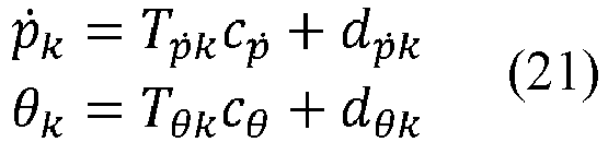

- p̈k represents a torso location of the torso of the legged robot within the k th control period. Tp̈ k represents a time matrix within the k th control period, where Tp̈ k is a constant. cp represents a third constant. In all embodiments of the present disclosure, an example in which a constant in the first relational data is the third constant is used for description. dp̈ k represents a constant matrix within the k th control period. ṗk represents a movement speed of the torso of the legged robot within the k th control period. Tp̈ k represents a time matrix within the k th control period, where Tp̈ k is a constant. cṗ represents a fourth constant with an undetermined value. dp̈ k represents a constant matrix within the k th control period. θk represents a rotational angle of the torso of the legged robot within the k th control period. Tθk represents a time matrix within the k th control period, where Tθk is a constant. cθ represents a fifth constant with an undetermined value. dθk represents a constant matrix within the k th control period. ωk represents an angular velocity of the torso of the legged robot within the k th control period. Tωk represents a time matrix within the k th control period, where Tωk is a constant. cω represents a sixth constant with an undetermined value. dωk represents a constant matrix within the k th control period.
- On the basis of generating the first relational data, the twelfth relational data, the fourteenth relational data, and the fifteenth relational data, in the created formula (20), C is a constant with an undetermined value, and the constant C with an undetermined value includes the first constant cp̈ , the second constant cω̇ ˙, the third constant cp, the fourth constant cṗ , the fifth constant cθ , and the sixth constant cω .
- In all embodiments of the present disclosure, a friction constraint on a contact point at which a foot of the legged robot is in contact with the ground is linearized to create a linear friction constraint. To avoid relative sliding when the foot is in contact with the ground during movement of the legged robot, that is, to avoid slipping when the foot is in contact with the ground, the foot of the legged robot needs to meet the following friction constraint when being in contact with the ground. In the following, the friction constraint is represented by a friction cone constraint:

- ni is a normal vector for a contact point at which an i th foot of the legged robot is in contact with the ground,

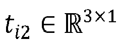
- The legged robot is limited by the friction constraint during movement of the legged robot. Therefore, directions of forces applied to the i th foot of the legged robot in contact with the ground are in a friction cone. In all embodiments of the present disclosure, a quadratic friction constraint may be approximately converted into a linear constraint by using a rectangular pyramid. Therefore, the created friction constraint meets the following relationships:


- µi is the friction coefficient. ni is the normal vector for the contact point at which the i th foot of the legged robot is in contact with the ground,
 represents a set of real numbers in multidimensional space. t i1 and t i2 represent two tangent vectors on the plane perpendicular to the normal vector for the contact point between the i th foot of the legged robot and the ground. The tangent vector t i1 is orthogonal to the tangent vector t i2 . t i1 and


- Based on the foregoing relational expressions, components, on the four sides of the rectangular pyramid, of the force fi applied to the i th foot of the legged robot in contact with the ground, and components, in the normal direction, of the force fi applied to the i th foot of the legged robot in contact with the ground are limited, so that a direction of the force fi applied to the i th foot of the legged robot in contact with the ground is limited within the rectangular pyramid.
- In all embodiments of the present disclosure, working space within which a foot of the legged robot is capable of moving may be linearized to create a linear spatial constraint. The working space for the foot of the legged robot is usually a non-convex region, and can be approximately a convex polyhedron. The convex polyhedron includes a plurality of faces, and each face is represented by the following linear inequality:

- sil represents an outer normal vector for an l th face of a convex polyhedron for an i th foot. A value of l is (1,2, ......, Ltotal ), and Ltotal is a positive integer not less than 4. xi represents a coordinate of a foothold location of the i th foot of the legged robot in a coordinate system of a shoulder joint of a leg to which the i th foot belongs. dil represents a projected value, in an outer normal direction of the l th face of the convex polyhedron, of a vector formed by an origin directed to any point on the l th face.
- Linear inequalities for the plurality of faces of the convex polyhedron for the foot of the legged robot are combined to obtain an initial spatial constraint. The initial spatial constraint meets the following relational expression:

- Si represents a set of outer normal vectors for a plurality of faces of the convex polyhedron for the i th foot. xi represents the coordinate of the foothold location of the i th foot of the legged robot in the coordinate system of the shoulder joint of the leg to which the i th foot belongs. di represents a set of projected values, in the outer normal direction of the l th face, of a vector formed by the origin directed to any point on the plurality of faces of the convex polyhedron for the i th foot. T indicates to transpose a matrix.
- In the foregoing inequalities, a working space constraint that the i th foot needs to meet during movement of the legged robot may be expressed in the following form:


- Si represents the set of outer normal vectors for the plurality of faces of the convex polyhedron for the i th foot. xi represents the coordinate of the foothold location of the i th foot of the legged robot in the coordinate system of the shoulder joint of the leg to which the i th foot belongs. di represents the set of projected values, in the outer normal direction of the l th face, of the vector formed by the origin directed to any point on the plurality of faces of the convex polyhedron for the i th foot. T indicates to transpose a matrix. R 0 represents the attitude of the torso of the legged robot in the world coordinate system at the initial time point. I represents an identity matrix. Tθ,k represents a time matrix in the seventeenth relational data, and the seventeenth relational data indicates a relationship between the rotational angle of the torso of the legged robot and the force applied to the foot of the legged robot in contact with the ground within the k th control period. cω̇ represents the second constant with an undetermined value.

- In the formula (26),


- Si represents the set of outer normal vectors for the plurality of faces of the convex polyhedron for the i th foot. xi represents the coordinate of the foothold location of the i th foot of the legged robot in the coordinate system of the shoulder joint of the leg to which the i th foot belongs. di represents the set of projected values, in the outer normal direction of the l th face, of the vector formed by the origin directed to any point on the plurality of faces of the convex polyhedron for the i th foot. T indicates to transpose a matrix. R 0 represents the attitude of the torso of the legged robot in the world coordinate system at the initial time point. I represents an identity matrix. Tθ,k represents a time matrix in the twelfth relational data, and the twelfth relational data indicates a relationship between the rotational angle of the torso of the legged robot and the force applied to the foot of the legged robot in contact with the ground within the k th control period. cω̇ represents the second constant with an undetermined value.

- The fourth relational data created by selecting the plurality of sampling time points within the target movement duration and based on the third relational data, the fifth relational data, the sixth relational data, the seventh relational data, the eighth relational data, the ninth relational data, the tenth relational data, the eleventh relational data, and the force applied to the foot of the legged robot in contact with the ground meets the following relationship:

- J represents the target value. Jgrf represents the weighted sum of squares of forces applied to the foot of the legged robot in contact with the ground. Jlen represents the sum of the weighted sum of squares of the plurality of distances and the weighted sum of squares of the plurality of rotational angle differences. Jtgt represents a weighted sum of squares of the difference between the target rotational angle and the predicted rotational angle, the difference between the target angular velocity and the predicted angular velocity, the difference between the target angular acceleration and the predicted angular acceleration, the difference between the target torso location and the predicted torso location, the difference between the target movement speed and the predicted movement speed, and the difference between the target acceleration and the predicted acceleration in a case that the legged robot is at the target location.
- After the fourth relational data is created, the value of the constant C in a case that the target value J is the minimum value is determined by using the created friction constraint and spatial constraint and the following relational expression:


- J represents the target value. Jgrf represents the weighted sum of squares of forces applied to the foot of the legged robot in contact with the ground. Jlen represents the sum of the weighted sum of squares of the plurality of distances and the weighted sum of squares of the plurality of rotational angle differences. Jtgt represents the weighted sum of squares of the difference between the target rotational angle and the predicted rotational angle, the difference between the target angular velocity and the predicted angular velocity, the difference between the target angular acceleration and the predicted angular acceleration, the difference between the target torso location and the predicted torso location, the difference between the target movement speed and the predicted movement speed, and the difference between the target acceleration and the predicted acceleration in a case that the legged robot is at the target location. Tk is a time matrix including the time matrix Tp̈ k and the time matrix Tω̇ k. C is a constant with an undetermined value, and the constant C with an undetermined value includes the first constant cp̈ and the second constant cω̇ with undetermined values. dk is a constant matrix including the constant matrices dp̈ k and dω̇ k within the k th control period. Ak is a coefficient matrix including the sixth coefficient matrix Aṗ ,k and the fourth coefficient matrix Aω̇
k ,k. bk is a constant matrix including the sixth constant matrix and the fourth constant matrix. µi is the friction coefficient. ni is the normal vector for the contact point at which the i th foot of the legged robot is in contact with the ground, represents a set of real numbers in multidimensional space. t i1 and t i2 represent two tangent vectors on the plane perpendicular to the normal vector for the contact point between the i th foot of the legged robot and the ground. The tangent vector t i1 is orthogonal to the tangent vector t i2. t i1 and


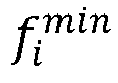


- In a possible implementation, the constant C with an undetermined value includes the first constant cp̈, the second constant cω̇ , the third constant cp, the fourth constant cṗ, the fifth constant cθ , and the sixth constant cω with undetermined values. Based on the foregoing relational data, after a value of the constant C is determined, values of the first constant cp̈ , the second constant cω̇ , the third constant cp, the fourth constant cṗ , the fifth constant cθ , and the sixth constant cω that are included in the constant C can be determined. A third constant cp with a determined value may be substituted into the formula in the first line of the formula (21) to obtain a movement trajectory of the torso of the legged robot. In addition, a first constant cp̈ , a second constant cω̇ , a fourth constant cṗ˙, a fifth constant cθ , and a sixth constant cω with determined values may be respectively substituted into corresponding formulas in the formula (19) and the formula (21) to obtain a speed trajectory, an acceleration trajectory, a rotational angle trajectory, an angular velocity trajectory, and an angular acceleration trajectory of the torso of the legged robot, so that the legged robot can be subsequently controlled to move based on the movement trajectory, the speed trajectory, the acceleration trajectory, the rotational angle trajectory, the angular velocity trajectory, and the angular acceleration trajectory of the torso of the legged robot.
- The movement trajectory determining method provided in all embodiments of the present disclosure may be applicable to a variety of legged robots, for example, a two-legged robot, a four-legged robot, or a six-legged robot; is applicable to a variety of gaits of a legged robot, for example, bipedal walking, quadrupedal walking, quadrupedal trotting, a random gait, or a diagonal gait; and is applicable to a variety of complex environments, for example, a flat ground, an uneven ground, a slope, or stairs. In addition to a ground force, a curve oscillation amplitude, and expected target status data, a sum of squares of accelerations, a sum of squares of speed differences between adjacent points, a sum of squares of acceleration differences, and the like may be further included in the fourth relational data. Location of a contact point: A contact point is not limited to a contact point between a foot of a legged robot and a ground, and is also applicable to contact between an environment and a part such as a body, a torso, or an upper limb of the legged robot. In addition, with respect to the friction constraint, an approximation of a friction cone corresponding to each foot is not limited to four edges. A larger quantity of faces of a pyramid of the friction cone indicates that the friction cone is more real. This ensures feasibility of a determined movement trajectory.
-
FIG. 16 is a schematic structural diagram of a movement trajectory determining apparatus according to an embodiment of the present disclosure. The apparatus is configured in a computer device. For example, the computer device is a legged robot or a control device. As shown inFIG. 16 , the apparatus includes:
a generating module 1601, configured to generate first relational data, second relational data, and third relational data, the first relational data indicating a first relationship between a torso location of a legged robot and movement duration, the second relational data indicating a second relationship between the movement duration and a force applied to a foot of the legged robot in contact with a ground, the third relational data indicating a third relationship between the force and a predicted rotational angle of the legged robot when the legged robot moves to a pre-determined target location and a pre-set movement duration expires, and the first relational data and the second relational data both including a constant C with an undetermined value, the generating module 1601 being further configured to generate fourth relational data based on the third relational data, the fourth relational data indicating a positive correlation between a target value J and a status data error, the status data error representing an error between predicted status data and target status data when the legged robot moves to the pre-determined target location and the pre-set movement duration expires, the target status data including a target rotational angle of the legged robot at the target location, and the predicted status data including the predicted rotational angle; and an obtaining module 1602, configured to determine, based on the second relational data and the fourth relational data, a value of the constant C in a case that the target value J is a minimum value, and updates the first relational data using the determined value of the constant C, the updated first relational data representing a movement trajectory of the torso of the legged robot. - In another possible implementation, the obtaining
module 1602 is configured to: determine, based on the fourth relational data, a value of the force in a case that the target value J is the minimum value; and determine the value of the constant C based on the value of the force, the target movement duration, and the second relational data. - In another possible implementation, the
generating module 1601 is further configured to: generate fifth relational data, the fifth relational data indicating a relationship between the force and a predicted angular velocity when the legged robot moves to the pre-determined target location and the pre-set movement duration expires; and generate the fourth relational data based on the third relational data and the fifth relational data, the target status data further including a target angular velocity of the legged robot at the target location, and the predicted status data further including the predicted angular velocity. - In another possible implementation, the
generating module 1601 is configured to set the target value J in the fourth relational data to a sum of squares of a first difference and a second difference, the first difference being a difference between the target rotational angle and the predicted rotational angle, and the second difference being a difference between the target angular velocity and the predicted angular velocity. - In another possible implementation, the
generating module 1601 is further configured to: generate sixth relational data, the sixth relational data indicating a relationship between the force and a predicted angular acceleration when the legged robot moves to the pre-determined target location and the pre-set movement duration expires; and generate the fourth relational data based on the third relational data and the sixth relational data, the target status data further including a target angular acceleration of the legged robot at the target location, and the predicted status data further including the predicted angular acceleration. - In another possible implementation, the
generating module 1601 is further configured to set the target value J in the fourth relational data to a sum of squares of a first difference and a third difference, the first difference being a difference between the target rotational angle and the predicted rotational angle, and the third difference being a difference between the target angular acceleration and the predicted angular acceleration. - In another possible implementation, the
generating module 1601 is further configured to: generate seventh relational data, the seventh relational data indicating a relationship between the force and a predicted torso location when the legged robot moves to the pre-determined target location and the pre-set movement duration expires; and generate the fourth relational data based on the third relational data and the seventh relational data, the target status data further including a target torso location of the legged robot at the target location, and the predicted status data further including the predicted torso location. - In another possible implementation, the
generating module 1601 is further configured to set the target value J in the fourth relational data to a sum of squares of a first difference and a fourth difference, the first difference being a difference between the target rotational angle and the predicted rotational angle, and the fourth difference being a difference between the target torso location and the predicted torso location. - In another possible implementation, the
generating module 1601 is further configured to: generate eighth relational data, the eighth relational data indicating a relationship between the force and a predicted movement speed when the legged robot moves to the pre-determined target location and the pre-set movement duration expires; and create the fourth relational data based on the third relational data and the eighth relational data, the target status data further including a target movement speed of the legged robot at the target location, and the predicted status data further including the predicted movement speed. - In another possible implementation, the
generating module 1601 is further configured to set the target value J in the fourth relational data to a sum of squares of a first difference and a fifth difference, the first difference being a difference between the target rotational angle and the predicted rotational angle, and the fifth difference being a difference between the target movement speed and the predicted movement speed. - In another possible implementation, the
generating module 1601 is further configured to: generate ninth relational data, the ninth relational data indicating a relationship between the force and a predicted acceleration when the legged robot moves to the pre-determined target location and the pre-set movement duration expires; and generate the fourth relational data based on the third relational data and the ninth relational data, the target status data further including a target acceleration of the legged robot at the target location, and the predicted status data further including the predicted acceleration. - In another possible implementation, the
generating module 1601 is further configured to set the target value J in the fourth relational data to a sum of squares of a first difference and a sixth difference, the first difference being a difference between the target rotational angle and the predicted rotational angle, and the sixth difference being a difference between the target acceleration and the predicted acceleration. - In another possible implementation, as shown in
FIG. 17 , the apparatus further includes: aselection module 1603, configured to select a plurality of sampling time points within the target movement duration, thegenerating module 1601 being further configured to generate tenth relational data for each sampling time point, the tenth relational data indicating a relationship between the force and a rotational angle of the legged robot after movement duration between the sampling time point and an initial time point elapses; and thegenerating module 1601 being configured to generate the fourth relational data based on the third relational data and the tenth relational data, the fourth relational data indicating a positive correlation between the target value J and the status data error and the rotational angle at the sampling time point. - In another possible implementation, the apparatus further includes: a
selection module 1603, configured to select a plurality of sampling time points within the target movement duration, thegenerating module 1601 being further configured to generate eleventh relational data for each sampling time point, the eleventh relational data indicating a relationship between the force and a predicted torso location of the legged robot after movement duration between the sampling time point and an initial time point elapses; and thegenerating module 1601 being configured to generate the fourth relational data based on the third relational data and the eleventh relational data, the fourth relational data indicating a positive correlation between the target value J and the status data error and the predicted torso location at each sampling time point. - In another possible implementation, the
generating module 1601 is further configured to generate a friction constraint, the friction constraint indicating a friction constraint met by the force applied to the foot of the legged robot in contact with the ground; and the obtainingmodule 1602 is configured to: in a case that the friction constraint is met, determine, based on the second relational data and the fourth relational data, the value of the constant C in a case that the target value J is the minimum value. - In another possible implementation, the
generating module 1601 is further configured to generate a spatial constraint on the foot of the legged robot, the spatial constraint indicating a spatial range within which the foot of the legged robot is capable of moving, and the spatial constraint including the constant C; and the obtainingmodule 1602 is configured to: in a case that the spatial constraint is met, determine, based on the second relational data and the fourth relational data, the value of the constant C in a case that the target value J is the minimum value. - In the movement trajectory determining apparatus provided in the foregoing embodiments of the present disclosure, the division of the foregoing functional modules is merely used as an example for description. In practical application, the functions may be allocated to and completed by different functional modules according to requirements. That is, an internal structure of a legged robot is divided into different functional modules, to complete all or some of the functions described above. In addition, the movement trajectory determining apparatus provided in the foregoing embodiments of the present disclosure and the movement trajectory determining method embodiments of the present disclosure belong to a same concept. For details about a specific implementation process of the movement trajectory determining apparatus, refer to the method embodiment. Details are not described herein again.
- An embodiment of the present disclosure further provides a legged robot, the legged robot including a processor and a memory, the memory storing at least one computer program, and the at least one computer program being loaded and executed by the processor to implement the operations performed in the movement trajectory determining method in the foregoing embodiments.
-
FIG. 18 is a schematic structural diagram of alegged robot 1800 according to an exemplary embodiment of the present disclosure. Thelegged robot 1800 is configured to perform the steps performed by the legged robot in the movement trajectory determining method. Thelegged robot 1800 includes aprocessor 1801 and amemory 1802. - The
processor 1801 may include one or more processing cores, for example, a 4-core processor or an 8-core processor. Theprocessor 1801 may be implemented in at least one hardware form of a digital signal processor (DSP), a field-programmable gate array (FPGA), and a programmable logic array (PLA). Thememory 1802 may include one or more computer-readable storage media. The computer-readable storage medium may be non-transient. Thememory 1802 may further include a high-speed random access memory and a nonvolatile memory, for example, one or more disk storage devices or flash storage devices. In all embodiments of the present disclosure, the non-transient computer-readable storage medium in thememory 1802 may be configured to store at least one computer program, and the at least one computer program is executed by theprocessor 1801 to implement the movement trajectory determining method provided in the method embodiments of the present disclosure. - In all embodiments of the present disclosure, the
legged robot 1800 may further include aperipheral device interface 1803 and at least one peripheral device. Theprocessor 1801, thememory 1802, and theperipheral device interface 1803 may be connected through a bus or a signal cable. Each peripheral device may be connected to theperipheral device interface 1803 through a bus, a signal cable, or a circuit board. Specifically, the peripheral device includes at least one of aradio frequency circuit 1804, acamera assembly 1805, and apositioning assembly 1806. - The
peripheral interface 1803 may be configured to connect the at least one peripheral related to input/output (I/O) to theprocessor 1801 and thememory 1802. In some embodiments, theprocessor 1801, thememory 1802, and theperipheral device interface 1803 may be integrated on one chip or circuit board. In some other embodiments, any one or two of theprocessor 1801, thememory 1802, and theperipheral device interface 1803 may be implemented on a separate chip or circuit board. - The
radio frequency circuit 1804 is configured to receive and transmit a radio frequency (RF) signal, also referred to as an electromagnetic signal. Theradio frequency circuit 1804 communicates with a communication network and other communication devices through the electromagnetic signal. Theradio frequency circuit 1804 converts an electrical signal into an electromagnetic signal for transmission, or converts a received electromagnetic signal into an electrical signal. Thecamera assembly 1805 is configured to capture an image or a video. In all embodiments of the present disclosure, thecamera assembly 1805 may include a front-facing camera and a rear-facing camera. In all embodiments of the present disclosure, thecamera assembly 1805 may further include a flash. The flash may be a monochrome temperature flash, or may be a double color temperature flash. Thepositioning assembly 1806 is configured to determine a current geographic location of thelegged robot 1800, to implement navigation or a location based service (LBS). - In all embodiments of the present disclosure, the
legged robot 1800 may further include one ormore sensors 1807. The one ormore sensors 1807 include but are not limited to anacceleration sensor 1808 and agyro sensor 1809. Theacceleration sensor 1808 may detect a magnitude of an acceleration on three coordinate axes of a coordinate system established based on thelegged robot 1800. For example, theacceleration sensor 1808 may be configured to detect components of an acceleration of gravity on the three coordinate axes. Thegyro sensor 1809 may detect a body direction and a rotational angle of thelegged robot 1800. Thegyro sensor 1809 may cooperate with theacceleration sensor 1808 to capture a 3D action performed by a user on thelegged robot 1800. - A person skilled in the art may understand that the structure shown in
FIG. 18 constitutes no limitation on thelegged robot 1800, and the terminal may include more or fewer components than those shown in the figure, or some components may be combined, or a different component layout may be used. - An embodiment of the present disclosure further provides a control device, the control device including a processor and a memory, the memory storing at least one computer program, and the at least one computer program being loaded and executed by the processor to implement the operations performed in the movement trajectory determining method in the foregoing embodiments.
- In all embodiments of the present disclosure, the control device may be provided as a server.
FIG. 19 is a schematic structural diagram of a control device according to an embodiment of the present disclosure. Theserver 1900 may vary greatly due to different configurations or performance, and may include one or more central processing units (CPUs) 1901 and one ormore memories 1902. Thememory 1902 stores at least one computer program, and the at least one computer program is loaded and executed by theCPU 1901 to implement the methods provided in the foregoing method embodiments. Certainly, the control device may further include components such as a wired or wireless network interface, a keyboard, and an input/output interface, to facilitate input and output. The control device may further include another component configured to implement a function of the device. Details are not described herein. - An embodiment of the present disclosure further provides a computer-readable storage medium. The computer-readable storage medium stores at least one computer program, and the at least one computer program is loaded and executed by a processor to implement the operations performed in the movement trajectory determining method in the foregoing embodiments.
- An embodiment of the present disclosure further provides a computer program product, including a computer program, the computer program, when being executed by a processor, implements the operations performed in the movement trajectory determining method according to the foregoing aspects.
- A person of ordinary skill in the art may understand that all or some of the steps of the foregoing embodiments may be implemented by hardware, or may be implemented by a program instructing relevant hardware. The program may be stored in a computer-readable storage medium. The storage medium may be a read-only memory, a magnetic disk, an optical disc, or the like.
- The foregoing descriptions are merely optional embodiments of the embodiments of the present disclosure, but are not intended to limit the embodiments of the present disclosure. Any modification, equivalent replacement, or improvement made within the spirit and principle of the embodiments of the present disclosure shall fall within the protection scope of the present disclosure.
Claims (21)
- A movement trajectory determining method, executable by a computer device, the method comprising:generating (201) first relational data, second relational data, and third relational data, the first relational data indicating a first relationship between a location of a torso of a legged robot and a movement duration, the second relational data indicating a second relationship between the movement duration and a force applied to a foot of the legged robot when the foot is in contact with a ground, the third relational data indicating a third relationship between the force and a predicted rotational angle of the legged robot when the legged robot moves to a pre-determined target location and a pre-set movement duration expires, and the first relational data and the second relational data both comprising a constant C;generating (202) fourth relational data based on the third relational data, the fourth relational data indicating a positive correlation between a target value J and a status data error, the status data error representing an error between predicted status data and target status data when the legged robot moves to the pre-determined target location and the pre-set movement duration expires, the target status data comprising a target rotational angle of the legged robot at the pre-determined target location, and the predicted status data comprising the predicted rotational angle; anddetermining (203), based on the second relational data and the fourth relational data, a value of the constant C in a case that the target value J is minimized, and updating the first relational data using the determined value of the constant C, the updated first relational data representing a movement trajectory of the torso of the legged robot.
- The method according to claim 1, wherein the determining, based on the second relational data and the fourth relational data, a value of the constant C in a case that the target value J is minimized comprises:determining, based on the fourth relational data, a value of the force in a case that the target value J is minimized; anddetermining the value of the constant C based on the value of the force, the pre-set movement duration, and the second relational data.
- The method according to claim 1, further comprising:generating fifth relational data, the fifth relational data indicating a relationship between the force and a predicted angular velocity when the legged robot moves to the pre-determined target location and the pre-set movement duration expires; andwherein the generating fourth relational data based on the third relational data comprises:
generating the fourth relational data based on the third relational data and the fifth relational data, the target status data further comprising a target angular velocity of the legged robot at the target location, and the predicted status data further comprising the predicted angular velocity. - The method according to claim 3, wherein the generating the fourth relational data based on the third relational data and the fifth relational data comprises:
setting the target value J in the fourth relational data to be a sum of squares of a first difference and a second difference, the first difference being a difference between the target rotational angle and the predicted rotational angle, and the second difference being a difference between the target angular velocity and the predicted angular velocity. - The method according to claim 1, further comprising:generating sixth relational data, the sixth relational data indicating a relationship between the force and a predicted angular acceleration when the legged robot moves to the pre-determined target location and the pre-set movement duration expires;wherein the generating fourth relational data based on the third relational data comprises: generating the fourth relational data based on the third relational data and the sixth relational data, the target status data further comprising a target angular acceleration of the legged robot at the target location, and the predicted status data further comprising the predicted angular acceleration.
- The method according to claim 5, wherein the generating the fourth relational data based on the third relational data and the sixth relational data comprises:
setting the target value J in the fourth relational data to be a sum of squares of a first difference and a third difference, the first difference being a difference between the target rotational angle and the predicted rotational angle, and the third difference being a difference between the target angular acceleration and the predicted angular acceleration. - The method according to claim 1, wherein further comprising:generating seventh relational data, the seventh relational data indicating a relationship between the force and a predicted location of the torso when the legged robot moves to the pre-determined target location and the pre-set movement duration expires;wherein the generating fourth relational data based on the third relational data comprises:
generating the fourth relational data based on the third relational data and the seventh relational data, the target status data further comprising a target torso location of the legged robot at the target location, and the predicted status data further comprising the predicted location of the torso. - The method according to claim 7, wherein the generating the fourth relational data based on the third relational data and the seventh relational data comprises:
setting the target value J in the fourth relational data to be a sum of squares of a first difference and a fourth difference, the first difference being a difference between the target rotational angle and the predicted rotational angle, and the fourth difference being a difference between the target torso location and the predicted location of the location. - The method according to claim 1, further comprising:generating eighth relational data, the eighth relational data indicating a relationship between the force and a predicted movement speed when the legged robot moves to the pre-determined target location and the pre-set movement duration expires;wherein the generating fourth relational data based on the third relational data comprises:
generating the fourth relational data based on the third relational data and the eighth relational data, the target status data further comprising a target movement speed of the legged robot at the target location, and the predicted status data further comprising the predicted movement speed. - The method according to claim 9, wherein the generating the fourth relational data based on the third relational data and the eighth relational data comprises:
setting the target value J in the fourth relational data to be a sum of squares of a first difference and a fifth difference, the first difference being a difference between the target rotational angle and the predicted rotational angle, and the fifth difference being a difference between the target movement speed and the predicted movement speed. - The method according to claim 1, further comprising:generating ninth relational data, the ninth relational data indicating a relationship between the force and a predicted acceleration when the legged robot moves to the pre-determined target location and the pre-set movement duration expires;wherein the generating fourth relational data based on the third relational data comprises:
generating the fourth relational data based on the third relational data and the ninth relational data, the target status data further comprising a target acceleration of the legged robot at the target location, and the predicted status data further comprising the predicted acceleration. - The method according to claim 11, wherein the generating the fourth relational data based on the third relational data and the ninth relational data comprises:
setting the target value J in the fourth relational data to be a sum of squares of a first difference and a sixth difference, the first difference being a difference between the target rotational angle and the predicted rotational angle, and the sixth difference being a difference between the target acceleration and the predicted acceleration. - The method according to claim 1, further comprising:selecting a plurality of sampling time points within the pre-set movement duration; andgenerating tenth relational data for each of the plurality of sampling time points, the tenth relational data indicating a relationship between the force and a rotational angle of the legged robot when a movement duration between the sampling time point and an initial time point expires;wherein the generating fourth relational data based on the third relational data, the fourth relational data indicating a positive correlation between a target value J and a status data error comprises:
generating the fourth relational data based on the third relational data and the tenth relational data, the fourth relational data indicating a positive correlation between the target value J, the status data error and the rotational angle at the sampling time point. - The method according to claim 1, further comprising:.selecting a plurality of sampling time points within the pre-set movement duration; andgenerating eleventh relational data for each of the plurality of sampling time points, the eleventh relational data indicating a relationship between the force and a predicted location of the torso of the legged robot when a movement duration between the sampling time point and an initial time point expires;wherein the generating fourth relational data based on the third relational data, the fourth relational data indicating a positive correlation between a target value J and a status data error comprises:
generating the fourth relational data based on the third relational data and the eleventh relational data, the fourth relational data indicating a positive correlation between the target value J, the status data error and the predicted location of the torso at the sampling time point. - The method according to any one of claims 1 to 14, further comprising:generating a friction constraint, the friction constraint indicating a friction constraint met by the force applied to the foot of the legged robot when the foot being in contact with the ground;wherein the determining, based on the second relational data and the fourth relational data, a value of the constant C in a case that the target value J is minimized comprises:
in a case that the friction constraint is met, determining, based on the second relational data and the fourth relational data, the value of the constant C in a case that the target value J is minimized. - The method according to any one of claims 1 to 14, the method further comprising:.generating a spatial constraint on the foot of the legged robot, the spatial constraint indicating a spatial range in which the foot of the legged robot is movable, and the spatial constraint comprising the constant C;wherein the determining, based on the second relational data and the fourth relational data, a value of the constant C in a case that the target value J is minimized comprises:
in a case that the spatial constraint is met, determining, based on the second relational data and the fourth relational data, the value of the constant C in a case that the target value J is minimized. - A movement trajectory determining apparatus, configured in a computer device, the apparatus comprising:a generating module, configured to generate first relational data, second relational data, and third relational data, the first relational data indicating a first relationship between a location of a torso of a legged robot and a movement duration, the second relational data indicating a second relationship between the movement duration and a force applied to a foot of the legged robot when the foot is in contact with a ground, the third relational data indicating a third relationship between the force and a predicted rotational angle of the legged robot when the legged robot moves to a pre-determined target location and a pre-set movement duration expires, and the first relational data and the second relational data both comprising a constant C,the generating module being further configured to generate fourth relational data based on the third relational data, the fourth relational data indicating a positive correlation between a target value J and a status data error, the status data error representing an error between predicted status data and target status data when the legged robot moves to the pre-determined target location and the pre-set movement duration expires, the target status data comprising a target rotational angle of the legged robot at the pre-determined target location, and the predicted status data comprising the predicted rotational angle; andan obtaining module, configured to determine, based on the second relational data and the fourth relational data, a value of the constant C in a case that the target value J is minimized, and updating the first relational data using the determined value of the constant C, the updated first relational data representing a movement trajectory of the torso of the legged robot.
- A legged robot, the legged robot comprising a processor and a memory, the memory storing at least one computer program, and the at least one computer program being loaded and executed by the processor to implement the operations performed in the movement trajectory determining method according to any one of claims 1 to 16.
- A control device, the control device comprising a processor and a memory, the memory storing at least one computer program, and the at least one computer program being loaded and executed by the processor to implement the operations performed in the movement trajectory determining method according to any one of claims 1 to 16.
- A computer-readable storage medium storing at least one computer program, wherein the at least one computer program is loaded and executed by a processor to implement the movement trajectory determining method according to any one of claims 1 to 14.
- A computer program product, comprising a computer program, the computer program, when being executed by a processor, implements the operations performed in the movement trajectory determining method according to any one of claims 1 to 16.
Applications Claiming Priority (2)
| Application Number | Priority Date | Filing Date | Title |
|---|---|---|---|
| CN202211088025.2A CN116991155B (en) | 2022-09-07 | 2022-09-07 | Method, device, computer equipment and storage medium for determining movement trajectory |
| PCT/CN2023/110838 WO2024051408A1 (en) | 2022-09-07 | 2023-08-02 | Moving trajectory determining method and apparatus, computer device, and storage medium |
Publications (3)
| Publication Number | Publication Date |
|---|---|
| EP4390594A1 true EP4390594A1 (en) | 2024-06-26 |
| EP4390594A4 EP4390594A4 (en) | 2024-12-18 |
| EP4390594B1 EP4390594B1 (en) | 2025-10-01 |
Family
ID=88525399
Family Applications (1)
| Application Number | Title | Priority Date | Filing Date |
|---|---|---|---|
| EP23862107.2A Active EP4390594B1 (en) | 2022-09-07 | 2023-08-02 | Moving trajectory determining method and apparatus, computer device, and storage medium |
Country Status (4)
| Country | Link |
|---|---|
| US (1) | US12632062B2 (en) |
| EP (1) | EP4390594B1 (en) |
| CN (1) | CN116991155B (en) |
| WO (1) | WO2024051408A1 (en) |
Family Cites Families (16)
| Publication number | Priority date | Publication date | Assignee | Title |
|---|---|---|---|---|
| JP4168943B2 (en) * | 2004-01-28 | 2008-10-22 | トヨタ自動車株式会社 | Legged robot and walking control method for legged robot |
| US7386264B2 (en) * | 2005-09-23 | 2008-06-10 | Lexmark International, Inc. | Fusing system including a backup belt assembly |
| JP4392037B2 (en) * | 2007-09-12 | 2009-12-24 | トヨタ自動車株式会社 | Legged robot and control method thereof |
| JP4440956B2 (en) * | 2007-09-12 | 2010-03-24 | トヨタ自動車株式会社 | Legged robot and control method thereof |
| KR101687631B1 (en) * | 2010-01-18 | 2016-12-20 | 삼성전자주식회사 | Walking control apparatus of robot and method for controlling the same |
| JP6228079B2 (en) * | 2014-07-16 | 2017-11-08 | 本田技研工業株式会社 | Mobile robot motion target generator |
| CN104374387B (en) | 2014-10-31 | 2017-12-19 | 清华大学 | A kind of motion path generation method |
| KR101795852B1 (en) * | 2015-06-26 | 2017-11-10 | 국방과학연구소 | Apparatus and method for controlling attitude of wearable robot in slope |
| CN110920769B (en) * | 2019-11-28 | 2020-12-15 | 深圳市优必选科技股份有限公司 | Robot's foot-waist coordination gait planning method, device, medium and robot |
| CN111506094A (en) * | 2020-04-14 | 2020-08-07 | 腾讯科技(深圳)有限公司 | Method, device, footed robot and storage medium for determining centroid position |
| EP4043991A4 (en) * | 2020-04-14 | 2023-02-08 | Tencent Technology (Shenzhen) Company Limited | BARYCENTRIC POSITION DETERMINATION METHOD AND DEVICE, WALKING ROBOT AND STORAGE MEDIA |
| CN114723807B (en) * | 2021-01-04 | 2025-03-04 | 腾讯科技(深圳)有限公司 | Method, device, footed robot, equipment and medium for determining center of mass trajectory |
| CN112783175B (en) * | 2021-01-04 | 2022-09-16 | 腾讯科技(深圳)有限公司 | Centroid trajectory determination method and device, foot type robot, equipment and medium |
| CN113534817B (en) * | 2021-08-19 | 2023-07-28 | 山东科技大学 | Dynamic modeling and track tracking control method and device for mobile robot |
| CN116774713B (en) * | 2022-03-11 | 2024-08-02 | 腾讯科技(深圳)有限公司 | Control method and device of wheel leg type robot, robot and storage medium |
| CN117590840A (en) * | 2022-08-08 | 2024-02-23 | 北京小米机器人技术有限公司 | Motion control methods, devices, controllers, media and robots |
-
2022
- 2022-09-07 CN CN202211088025.2A patent/CN116991155B/en active Active
-
2023
- 2023-08-02 WO PCT/CN2023/110838 patent/WO2024051408A1/en not_active Ceased
- 2023-08-02 EP EP23862107.2A patent/EP4390594B1/en active Active
-
2024
- 2024-04-03 US US18/626,088 patent/US12632062B2/en active Active
Also Published As
| Publication number | Publication date |
|---|---|
| WO2024051408A1 (en) | 2024-03-14 |
| US20240255954A1 (en) | 2024-08-01 |
| EP4390594B1 (en) | 2025-10-01 |
| EP4390594A4 (en) | 2024-12-18 |
| CN116991155B (en) | 2025-04-18 |
| US12632062B2 (en) | 2026-05-19 |
| CN116991155A (en) | 2023-11-03 |
Similar Documents
| Publication | Publication Date | Title |
|---|---|---|
| CN113534828B (en) | Centroid position determining method and device, foot type robot and storage medium | |
| EP4393657A1 (en) | Method, apparatus and device for controlling legged robot, legged robot, computer-readable storage medium and computer program product | |
| García Carrillo et al. | Combining stereo vision and inertial navigation system for a quad-rotor UAV | |
| EP4116782A1 (en) | Legged robot movement control method, apparatus and device, and medium | |
| CN112783175B (en) | Centroid trajectory determination method and device, foot type robot, equipment and medium | |
| US12552028B2 (en) | Barycenter position determining method and apparatus, legged robot, and storage medium | |
| US20240157555A1 (en) | Method, apparatus, and electronic device for controlling legged robot, computer-readable storage medium, computer program product, and legged robot | |
| Kulkarni et al. | Aerial gym simulator: A framework for highly parallelized simulation of aerial robots | |
| Hong et al. | Quadrotor path planning using A* search algorithm and minimum snap trajectory generation | |
| CN113984068B (en) | Positioning method, positioning device and computer readable storage medium | |
| Tweddle | Computer vision based navigation for spacecraft proximity operations | |
| CN118672256A (en) | Omnidirectional quadruped robot energy-saving motion planning method based on dynamics model | |
| EP4390594B1 (en) | Moving trajectory determining method and apparatus, computer device, and storage medium | |
| CN114723807B (en) | Method, device, footed robot, equipment and medium for determining center of mass trajectory | |
| Cook et al. | Unmanned aerial system for first responders | |
| HK40100930A (en) | Method, device, computer equipment and storage medium for determining movement trajectory | |
| HK40100930B (en) | Method, device, computer equipment and storage medium for determining movement trajectory | |
| CN115963858A (en) | Unmanned aerial vehicle flight control method, device, equipment and storage medium | |
| HK40070351B (en) | Method and apparatus for determining center of mass trajectory, footed robot, device and medium | |
| HK40070351A (en) | Method and apparatus for determining center of mass trajectory, footed robot, device and medium | |
| HK40055208B (en) | Method and device for determining centroid position, foot-type robot and storage medium | |
| HK40043820A (en) | Method and apparatus for determining centroid trajectory, foot-type robot, device, and medium | |
| HK40043820B (en) | Method and apparatus for determining centroid trajectory, foot-type robot, device, and medium | |
| HK40055208A (en) | Method and device for determining centroid position, foot-type robot and storage medium | |
| HK40027867A (en) | Method and device for determining position of center of mass, footed robot, and storage medium |
Legal Events
| Date | Code | Title | Description |
|---|---|---|---|
| STAA | Information on the status of an ep patent application or granted ep patent |
Free format text: STATUS: THE INTERNATIONAL PUBLICATION HAS BEEN MADE |
|
| PUAI | Public reference made under article 153(3) epc to a published international application that has entered the european phase |
Free format text: ORIGINAL CODE: 0009012 |
|
| STAA | Information on the status of an ep patent application or granted ep patent |
Free format text: STATUS: REQUEST FOR EXAMINATION WAS MADE |
|
| 17P | Request for examination filed |
Effective date: 20240318 |
|
| AK | Designated contracting states |
Kind code of ref document: A1 Designated state(s): AL AT BE BG CH CY CZ DE DK EE ES FI FR GB GR HR HU IE IS IT LI LT LU LV MC ME MK MT NL NO PL PT RO RS SE SI SK SM TR |
|
| REG | Reference to a national code |
Ref legal event code: R079 Ipc: B62D0057032000 Ref country code: DE Ref legal event code: R079 Ref document number: 602023007205 Country of ref document: DE Free format text: PREVIOUS MAIN CLASS: H99Z9999999999 Ipc: B62D0057032000 |
|
| A4 | Supplementary search report drawn up and despatched |
Effective date: 20241118 |
|
| RIC1 | Information provided on ipc code assigned before grant |
Ipc: B62D 57/032 20060101AFI20241112BHEP |
|
| GRAP | Despatch of communication of intention to grant a patent |
Free format text: ORIGINAL CODE: EPIDOSNIGR1 |
|
| STAA | Information on the status of an ep patent application or granted ep patent |
Free format text: STATUS: GRANT OF PATENT IS INTENDED |
|
| RIC1 | Information provided on ipc code assigned before grant |
Ipc: B62D 57/032 20060101AFI20250221BHEP |
|
| DAV | Request for validation of the european patent (deleted) | ||
| DAX | Request for extension of the european patent (deleted) | ||
| INTG | Intention to grant announced |
Effective date: 20250306 |
|
| GRAS | Grant fee paid |
Free format text: ORIGINAL CODE: EPIDOSNIGR3 |
|
| GRAA | (expected) grant |
Free format text: ORIGINAL CODE: 0009210 |
|
| STAA | Information on the status of an ep patent application or granted ep patent |
Free format text: STATUS: THE PATENT HAS BEEN GRANTED |
|
| AK | Designated contracting states |
Kind code of ref document: B1 Designated state(s): AL AT BE BG CH CY CZ DE DK EE ES FI FR GB GR HR HU IE IS IT LI LT LU LV MC ME MK MT NL NO PL PT RO RS SE SI SK SM TR |
|
| REG | Reference to a national code |
Ref country code: GB Ref legal event code: FG4D Ref country code: CH Ref legal event code: F10 Free format text: ST27 STATUS EVENT CODE: U-0-0-F10-F00 (AS PROVIDED BY THE NATIONAL OFFICE) Effective date: 20251001 |
|
| REG | Reference to a national code |
Ref country code: IE Ref legal event code: FG4D |
|
| REG | Reference to a national code |
Ref country code: DE Ref legal event code: R096 Ref document number: 602023007205 Country of ref document: DE |
|
| REG | Reference to a national code |
Ref country code: NL Ref legal event code: MP Effective date: 20251001 |
|
| REG | Reference to a national code |
Ref country code: AT Ref legal event code: MK05 Ref document number: 1842270 Country of ref document: AT Kind code of ref document: T Effective date: 20251001 |
|
| PG25 | Lapsed in a contracting state [announced via postgrant information from national office to epo] |
Ref country code: NL Free format text: LAPSE BECAUSE OF FAILURE TO SUBMIT A TRANSLATION OF THE DESCRIPTION OR TO PAY THE FEE WITHIN THE PRESCRIBED TIME-LIMIT Effective date: 20251001 |
|
| PG25 | Lapsed in a contracting state [announced via postgrant information from national office to epo] |
Ref country code: ES Free format text: LAPSE BECAUSE OF FAILURE TO SUBMIT A TRANSLATION OF THE DESCRIPTION OR TO PAY THE FEE WITHIN THE PRESCRIBED TIME-LIMIT Effective date: 20251001 |
|
| REG | Reference to a national code |
Ref country code: LT Ref legal event code: MG9D |
|
| PG25 | Lapsed in a contracting state [announced via postgrant information from national office to epo] |
Ref country code: NO Free format text: LAPSE BECAUSE OF FAILURE TO SUBMIT A TRANSLATION OF THE DESCRIPTION OR TO PAY THE FEE WITHIN THE PRESCRIBED TIME-LIMIT Effective date: 20260101 |
|
| PG25 | Lapsed in a contracting state [announced via postgrant information from national office to epo] |
Ref country code: AT Free format text: LAPSE BECAUSE OF FAILURE TO SUBMIT A TRANSLATION OF THE DESCRIPTION OR TO PAY THE FEE WITHIN THE PRESCRIBED TIME-LIMIT Effective date: 20251001 Ref country code: FI Free format text: LAPSE BECAUSE OF FAILURE TO SUBMIT A TRANSLATION OF THE DESCRIPTION OR TO PAY THE FEE WITHIN THE PRESCRIBED TIME-LIMIT Effective date: 20251001 Ref country code: HR Free format text: LAPSE BECAUSE OF FAILURE TO SUBMIT A TRANSLATION OF THE DESCRIPTION OR TO PAY THE FEE WITHIN THE PRESCRIBED TIME-LIMIT Effective date: 20251001 |
|
| PG25 | Lapsed in a contracting state [announced via postgrant information from national office to epo] |
Ref country code: RS Free format text: LAPSE BECAUSE OF FAILURE TO SUBMIT A TRANSLATION OF THE DESCRIPTION OR TO PAY THE FEE WITHIN THE PRESCRIBED TIME-LIMIT Effective date: 20260101 |
|
| PG25 | Lapsed in a contracting state [announced via postgrant information from national office to epo] |
Ref country code: IS Free format text: LAPSE BECAUSE OF FAILURE TO SUBMIT A TRANSLATION OF THE DESCRIPTION OR TO PAY THE FEE WITHIN THE PRESCRIBED TIME-LIMIT Effective date: 20260201 |
|
| PG25 | Lapsed in a contracting state [announced via postgrant information from national office to epo] |
Ref country code: PT Free format text: LAPSE BECAUSE OF FAILURE TO SUBMIT A TRANSLATION OF THE DESCRIPTION OR TO PAY THE FEE WITHIN THE PRESCRIBED TIME-LIMIT Effective date: 20260202 Ref country code: CZ Free format text: LAPSE BECAUSE OF FAILURE TO SUBMIT A TRANSLATION OF THE DESCRIPTION OR TO PAY THE FEE WITHIN THE PRESCRIBED TIME-LIMIT Effective date: 20251001 |
|
| PG25 | Lapsed in a contracting state [announced via postgrant information from national office to epo] |
Ref country code: PL Free format text: LAPSE BECAUSE OF FAILURE TO SUBMIT A TRANSLATION OF THE DESCRIPTION OR TO PAY THE FEE WITHIN THE PRESCRIBED TIME-LIMIT Effective date: 20251001 |
|
| PG25 | Lapsed in a contracting state [announced via postgrant information from national office to epo] |
Ref country code: LV Free format text: LAPSE BECAUSE OF FAILURE TO SUBMIT A TRANSLATION OF THE DESCRIPTION OR TO PAY THE FEE WITHIN THE PRESCRIBED TIME-LIMIT Effective date: 20251001 |
|
| PG25 | Lapsed in a contracting state [announced via postgrant information from national office to epo] |
Ref country code: BG Free format text: LAPSE BECAUSE OF FAILURE TO SUBMIT A TRANSLATION OF THE DESCRIPTION OR TO PAY THE FEE WITHIN THE PRESCRIBED TIME-LIMIT Effective date: 20251001 |
|
| PG25 | Lapsed in a contracting state [announced via postgrant information from national office to epo] |
Ref country code: LT Free format text: LAPSE BECAUSE OF FAILURE TO SUBMIT A TRANSLATION OF THE DESCRIPTION OR TO PAY THE FEE WITHIN THE PRESCRIBED TIME-LIMIT Effective date: 20251001 |
|
| PG25 | Lapsed in a contracting state [announced via postgrant information from national office to epo] |
Ref country code: SM Free format text: LAPSE BECAUSE OF FAILURE TO SUBMIT A TRANSLATION OF THE DESCRIPTION OR TO PAY THE FEE WITHIN THE PRESCRIBED TIME-LIMIT Effective date: 20251001 |
|
| PG25 | Lapsed in a contracting state [announced via postgrant information from national office to epo] |
Ref country code: DK Free format text: LAPSE BECAUSE OF FAILURE TO SUBMIT A TRANSLATION OF THE DESCRIPTION OR TO PAY THE FEE WITHIN THE PRESCRIBED TIME-LIMIT Effective date: 20251001 |
|
| PG25 | Lapsed in a contracting state [announced via postgrant information from national office to epo] |
Ref country code: IT Free format text: LAPSE BECAUSE OF FAILURE TO SUBMIT A TRANSLATION OF THE DESCRIPTION OR TO PAY THE FEE WITHIN THE PRESCRIBED TIME-LIMIT Effective date: 20251001 |
|
| PG25 | Lapsed in a contracting state [announced via postgrant information from national office to epo] |
Ref country code: EE Free format text: LAPSE BECAUSE OF FAILURE TO SUBMIT A TRANSLATION OF THE DESCRIPTION OR TO PAY THE FEE WITHIN THE PRESCRIBED TIME-LIMIT Effective date: 20251001 |
|
| PG25 | Lapsed in a contracting state [announced via postgrant information from national office to epo] |
Ref country code: SK Free format text: LAPSE BECAUSE OF FAILURE TO SUBMIT A TRANSLATION OF THE DESCRIPTION OR TO PAY THE FEE WITHIN THE PRESCRIBED TIME-LIMIT Effective date: 20251001 |
|
| PG25 | Lapsed in a contracting state [announced via postgrant information from national office to epo] |
Ref country code: SE Free format text: LAPSE BECAUSE OF FAILURE TO SUBMIT A TRANSLATION OF THE DESCRIPTION OR TO PAY THE FEE WITHIN THE PRESCRIBED TIME-LIMIT Effective date: 20251001 |
|
| PLBE | No opposition filed within time limit |
Free format text: ORIGINAL CODE: 0009261 |
|
| STAA | Information on the status of an ep patent application or granted ep patent |
Free format text: STATUS: NO OPPOSITION FILED WITHIN TIME LIMIT |
|
| REG | Reference to a national code |
Ref country code: CH Ref legal event code: L10 Free format text: ST27 STATUS EVENT CODE: U-0-0-L10-L00 (AS PROVIDED BY THE NATIONAL OFFICE) Effective date: 20260812 |