EP4390507A1 - Image irradiation device - Google Patents
Image irradiation device Download PDFInfo
- Publication number
- EP4390507A1 EP4390507A1 EP22858391.0A EP22858391A EP4390507A1 EP 4390507 A1 EP4390507 A1 EP 4390507A1 EP 22858391 A EP22858391 A EP 22858391A EP 4390507 A1 EP4390507 A1 EP 4390507A1
- Authority
- EP
- European Patent Office
- Prior art keywords
- columnar protrusions
- housing
- light
- image
- columnar
- Prior art date
- Legal status (The legal status is an assumption and is not a legal conclusion. Google has not performed a legal analysis and makes no representation as to the accuracy of the status listed.)
- Withdrawn
Links
Images


Classifications
-
- G—PHYSICS
- G03—PHOTOGRAPHY; CINEMATOGRAPHY; ANALOGOUS TECHNIQUES USING WAVES OTHER THAN OPTICAL WAVES; ELECTROGRAPHY; HOLOGRAPHY
- G03B—APPARATUS OR ARRANGEMENTS FOR TAKING PHOTOGRAPHS OR FOR PROJECTING OR VIEWING THEM; APPARATUS OR ARRANGEMENTS EMPLOYING ANALOGOUS TECHNIQUES USING WAVES OTHER THAN OPTICAL WAVES; ACCESSORIES THEREFOR
- G03B21/00—Projectors or projection-type viewers; Accessories therefor
- G03B21/14—Details
- G03B21/145—Housing details, e.g. position adjustments thereof
-
- B—PERFORMING OPERATIONS; TRANSPORTING
- B60—VEHICLES IN GENERAL
- B60K—ARRANGEMENT OR MOUNTING OF PROPULSION UNITS OR OF TRANSMISSIONS IN VEHICLES; ARRANGEMENT OR MOUNTING OF PLURAL DIVERSE PRIME-MOVERS IN VEHICLES; AUXILIARY DRIVES FOR VEHICLES; INSTRUMENTATION OR DASHBOARDS FOR VEHICLES; ARRANGEMENTS IN CONNECTION WITH COOLING, AIR INTAKE, GAS EXHAUST OR FUEL SUPPLY OF PROPULSION UNITS IN VEHICLES
- B60K35/00—Instruments specially adapted for vehicles; Arrangement of instruments in or on vehicles
- B60K35/20—Output arrangements, i.e. from vehicle to user, associated with vehicle functions or specially adapted therefor
- B60K35/21—Output arrangements, i.e. from vehicle to user, associated with vehicle functions or specially adapted therefor using visual output, e.g. blinking lights or matrix displays
- B60K35/22—Display screens
-
- B—PERFORMING OPERATIONS; TRANSPORTING
- B60—VEHICLES IN GENERAL
- B60K—ARRANGEMENT OR MOUNTING OF PROPULSION UNITS OR OF TRANSMISSIONS IN VEHICLES; ARRANGEMENT OR MOUNTING OF PLURAL DIVERSE PRIME-MOVERS IN VEHICLES; AUXILIARY DRIVES FOR VEHICLES; INSTRUMENTATION OR DASHBOARDS FOR VEHICLES; ARRANGEMENTS IN CONNECTION WITH COOLING, AIR INTAKE, GAS EXHAUST OR FUEL SUPPLY OF PROPULSION UNITS IN VEHICLES
- B60K35/00—Instruments specially adapted for vehicles; Arrangement of instruments in or on vehicles
- B60K35/20—Output arrangements, i.e. from vehicle to user, associated with vehicle functions or specially adapted therefor
- B60K35/21—Output arrangements, i.e. from vehicle to user, associated with vehicle functions or specially adapted therefor using visual output, e.g. blinking lights or matrix displays
- B60K35/23—Head-up displays [HUD]
-
- B—PERFORMING OPERATIONS; TRANSPORTING
- B60—VEHICLES IN GENERAL
- B60K—ARRANGEMENT OR MOUNTING OF PROPULSION UNITS OR OF TRANSMISSIONS IN VEHICLES; ARRANGEMENT OR MOUNTING OF PLURAL DIVERSE PRIME-MOVERS IN VEHICLES; AUXILIARY DRIVES FOR VEHICLES; INSTRUMENTATION OR DASHBOARDS FOR VEHICLES; ARRANGEMENTS IN CONNECTION WITH COOLING, AIR INTAKE, GAS EXHAUST OR FUEL SUPPLY OF PROPULSION UNITS IN VEHICLES
- B60K35/00—Instruments specially adapted for vehicles; Arrangement of instruments in or on vehicles
- B60K35/40—Instruments specially adapted for improving the visibility thereof to the user, e.g. fogging prevention or anti-reflection arrangements
- B60K35/425—Anti-reflection arrangements
-
- B—PERFORMING OPERATIONS; TRANSPORTING
- B60—VEHICLES IN GENERAL
- B60K—ARRANGEMENT OR MOUNTING OF PROPULSION UNITS OR OF TRANSMISSIONS IN VEHICLES; ARRANGEMENT OR MOUNTING OF PLURAL DIVERSE PRIME-MOVERS IN VEHICLES; AUXILIARY DRIVES FOR VEHICLES; INSTRUMENTATION OR DASHBOARDS FOR VEHICLES; ARRANGEMENTS IN CONNECTION WITH COOLING, AIR INTAKE, GAS EXHAUST OR FUEL SUPPLY OF PROPULSION UNITS IN VEHICLES
- B60K35/00—Instruments specially adapted for vehicles; Arrangement of instruments in or on vehicles
- B60K35/60—Instruments characterised by their location or relative disposition in or on vehicles
-
- G—PHYSICS
- G02—OPTICS
- G02B—OPTICAL ELEMENTS, SYSTEMS OR APPARATUS
- G02B27/00—Optical systems or apparatus not provided for by any of the groups G02B1/00 - G02B26/00, G02B30/00
- G02B27/0018—Optical systems or apparatus not provided for by any of the groups G02B1/00 - G02B26/00, G02B30/00 with means for preventing ghost images
-
- G—PHYSICS
- G02—OPTICS
- G02B—OPTICAL ELEMENTS, SYSTEMS OR APPARATUS
- G02B27/00—Optical systems or apparatus not provided for by any of the groups G02B1/00 - G02B26/00, G02B30/00
- G02B27/01—Head-up displays
-
- G—PHYSICS
- G02—OPTICS
- G02B—OPTICAL ELEMENTS, SYSTEMS OR APPARATUS
- G02B5/00—Optical elements other than lenses
- G02B5/02—Diffusing elements; Afocal elements
- G02B5/0205—Diffusing elements; Afocal elements characterised by the diffusing properties
- G02B5/021—Diffusing elements; Afocal elements characterised by the diffusing properties the diffusion taking place at the element's surface, e.g. by means of surface roughening or microprismatic structures
- G02B5/0215—Diffusing elements; Afocal elements characterised by the diffusing properties the diffusion taking place at the element's surface, e.g. by means of surface roughening or microprismatic structures the surface having a regular structure
-
- G—PHYSICS
- G02—OPTICS
- G02B—OPTICAL ELEMENTS, SYSTEMS OR APPARATUS
- G02B5/00—Optical elements other than lenses
- G02B5/02—Diffusing elements; Afocal elements
- G02B5/0273—Diffusing elements; Afocal elements characterized by the use
- G02B5/0284—Diffusing elements; Afocal elements characterized by the use used in reflection
-
- G—PHYSICS
- G03—PHOTOGRAPHY; CINEMATOGRAPHY; ANALOGOUS TECHNIQUES USING WAVES OTHER THAN OPTICAL WAVES; ELECTROGRAPHY; HOLOGRAPHY
- G03B—APPARATUS OR ARRANGEMENTS FOR TAKING PHOTOGRAPHS OR FOR PROJECTING OR VIEWING THEM; APPARATUS OR ARRANGEMENTS EMPLOYING ANALOGOUS TECHNIQUES USING WAVES OTHER THAN OPTICAL WAVES; ACCESSORIES THEREFOR
- G03B21/00—Projectors or projection-type viewers; Accessories therefor
- G03B21/10—Projectors with built-in or built-on screen
-
- G—PHYSICS
- G03—PHOTOGRAPHY; CINEMATOGRAPHY; ANALOGOUS TECHNIQUES USING WAVES OTHER THAN OPTICAL WAVES; ELECTROGRAPHY; HOLOGRAPHY
- G03B—APPARATUS OR ARRANGEMENTS FOR TAKING PHOTOGRAPHS OR FOR PROJECTING OR VIEWING THEM; APPARATUS OR ARRANGEMENTS EMPLOYING ANALOGOUS TECHNIQUES USING WAVES OTHER THAN OPTICAL WAVES; ACCESSORIES THEREFOR
- G03B21/00—Projectors or projection-type viewers; Accessories therefor
- G03B21/14—Details
- G03B21/16—Cooling; Preventing overheating
-
- G—PHYSICS
- G03—PHOTOGRAPHY; CINEMATOGRAPHY; ANALOGOUS TECHNIQUES USING WAVES OTHER THAN OPTICAL WAVES; ELECTROGRAPHY; HOLOGRAPHY
- G03B—APPARATUS OR ARRANGEMENTS FOR TAKING PHOTOGRAPHS OR FOR PROJECTING OR VIEWING THEM; APPARATUS OR ARRANGEMENTS EMPLOYING ANALOGOUS TECHNIQUES USING WAVES OTHER THAN OPTICAL WAVES; ACCESSORIES THEREFOR
- G03B21/00—Projectors or projection-type viewers; Accessories therefor
- G03B21/14—Details
- G03B21/28—Reflectors in projection beam
-
- G—PHYSICS
- G03—PHOTOGRAPHY; CINEMATOGRAPHY; ANALOGOUS TECHNIQUES USING WAVES OTHER THAN OPTICAL WAVES; ELECTROGRAPHY; HOLOGRAPHY
- G03B—APPARATUS OR ARRANGEMENTS FOR TAKING PHOTOGRAPHS OR FOR PROJECTING OR VIEWING THEM; APPARATUS OR ARRANGEMENTS EMPLOYING ANALOGOUS TECHNIQUES USING WAVES OTHER THAN OPTICAL WAVES; ACCESSORIES THEREFOR
- G03B21/00—Projectors or projection-type viewers; Accessories therefor
- G03B21/54—Accessories
- G03B21/56—Projection screens
- G03B21/60—Projection screens characterised by the nature of the surface
- G03B21/62—Translucent screens
-
- B—PERFORMING OPERATIONS; TRANSPORTING
- B60—VEHICLES IN GENERAL
- B60K—ARRANGEMENT OR MOUNTING OF PROPULSION UNITS OR OF TRANSMISSIONS IN VEHICLES; ARRANGEMENT OR MOUNTING OF PLURAL DIVERSE PRIME-MOVERS IN VEHICLES; AUXILIARY DRIVES FOR VEHICLES; INSTRUMENTATION OR DASHBOARDS FOR VEHICLES; ARRANGEMENTS IN CONNECTION WITH COOLING, AIR INTAKE, GAS EXHAUST OR FUEL SUPPLY OF PROPULSION UNITS IN VEHICLES
- B60K2360/00—Indexing scheme associated with groups B60K35/00 or B60K37/00 relating to details of instruments or dashboards
- B60K2360/20—Optical features of instruments
- B60K2360/23—Optical features of instruments using reflectors
-
- B—PERFORMING OPERATIONS; TRANSPORTING
- B60—VEHICLES IN GENERAL
- B60K—ARRANGEMENT OR MOUNTING OF PROPULSION UNITS OR OF TRANSMISSIONS IN VEHICLES; ARRANGEMENT OR MOUNTING OF PLURAL DIVERSE PRIME-MOVERS IN VEHICLES; AUXILIARY DRIVES FOR VEHICLES; INSTRUMENTATION OR DASHBOARDS FOR VEHICLES; ARRANGEMENTS IN CONNECTION WITH COOLING, AIR INTAKE, GAS EXHAUST OR FUEL SUPPLY OF PROPULSION UNITS IN VEHICLES
- B60K35/00—Instruments specially adapted for vehicles; Arrangement of instruments in or on vehicles
- B60K35/20—Output arrangements, i.e. from vehicle to user, associated with vehicle functions or specially adapted therefor
- B60K35/21—Output arrangements, i.e. from vehicle to user, associated with vehicle functions or specially adapted therefor using visual output, e.g. blinking lights or matrix displays
- B60K35/23—Head-up displays [HUD]
- B60K35/231—Head-up displays [HUD] characterised by their arrangement or structure for integration into vehicles
-
- G—PHYSICS
- G02—OPTICS
- G02B—OPTICAL ELEMENTS, SYSTEMS OR APPARATUS
- G02B27/00—Optical systems or apparatus not provided for by any of the groups G02B1/00 - G02B26/00, G02B30/00
- G02B27/01—Head-up displays
- G02B27/0101—Head-up displays characterised by optical features
- G02B2027/0118—Head-up displays characterised by optical features comprising devices for improving the contrast of the display / brillance control visibility
- G02B2027/012—Head-up displays characterised by optical features comprising devices for improving the contrast of the display / brillance control visibility comprising devices for attenuating parasitic image effects
-
- G—PHYSICS
- G02—OPTICS
- G02B—OPTICAL ELEMENTS, SYSTEMS OR APPARATUS
- G02B27/00—Optical systems or apparatus not provided for by any of the groups G02B1/00 - G02B26/00, G02B30/00
- G02B27/01—Head-up displays
- G02B27/0101—Head-up displays characterised by optical features
Definitions
- the present invention relates to an image projection device configured to project a display image on an image display board.
- an image projection device has been known as an in-vehicle image projection device.
- the image projection device is configured to, when disposed in a vehicle cabin, project a display image on an image display board such as a front window or a light-transmitting board disposed on a vehicle cabin side of the front window.
- This image projection device has a configuration including an image generation unit that generates a display image and a housing that accommodates the image generation unit, as described in, for example, "Patent Document 1".
- Patent Document 1 Japanese Unexamined Patent Application Publication No. 2021-890 ( JP 2021-890 A )
- a part of the light emitted from the image generation unit may be reflected on the inner surface of the housing, resulting in stray light reaching an image display board. Then, the stray light that has reached the image display board may cause unintended and unnecessary images to be formed in the peripheral area of a display image.
- sunlight that has entered the vehicle cabin through the front window, etc. may enter the internal space of the housing and become stray light by being reflected on the inner surface of the housing.
- the present invention has been made in view of the above circumstances, and it is an object of the present invention to provide an image projection device that is configured to project a display image on an image display board, and that allows effectively suppressing the formation of unnecessary images in the peripheral area of the display image due to the generation of stray light.
- the present invention aims to achieve the above object by devising a configuration of a housing.
- an image projection device configured to project a display image on an image display board is characterized in that: the image projection device includes an image generation unit that generates the display image, and a housing that accommodates the image generation unit; a plurality of columnar protrusions is formed on an inner surface of the housing; and a second columnar protrusion having a lower height than each of the plurality of the columnar protrusions is formed between the plurality of the columnar protrusions.
- image projection device is not particularly limited in its specific use as long as the device is configured to project the display image on the image display board.
- applications such as an in-vehicle head-up display can be adopted.
- image display board is not particularly limited in its specific configuration as long as the board is configured to project the display image.
- the front window of a vehicle or a light-transmitting board, etc. disposed on a vehicle cabin side of the front window can be adopted.
- the above “plurality of columnar protrusions” is formed on the inner surface of the housing, but a specific area where the columnar protrusions are formed is not particularly limited.
- the columnar protrusions may be formed in the entire area of the inner surface of the housing or in a partial area of the inner surface.
- a specific height, a cross-sectional shape, etc. of each of the "plurality of columnar protrusions” are not particularly limited.
- columnar protrusions formed in a columnar shape or a prismatic shape can be adopted.
- the "second columnar protrusion” is not particularly limited in its specific height, cross-sectional shape, etc., as long as the second columnar protrusion is formed to have a lower height than each of the plurality of the columnar protrusions.
- the image projection device is configured to project the display image on the image display board, and the image generation unit that generates the display image is housed in the housing.
- the plurality of the columnar protrusions is formed on the inner surface of the housing, and the second columnar protrusion having a lower height than each of the plurality of the columnar protrusions is formed between the plurality of the columnar protrusions. Therefore, the following effects can be obtained.
- the plurality of the columnar protrusions and the second columnar protrusions are formed in a reaching area of the light. Therefore, the light that has reached the inner surface can be reflected multiple times between the plurality of the columnar protrusions and between the plurality of the columnar protrusions and the second columnar protrusions, which can effectively attenuate intensity of the light. Accordingly, a proportion of the light that reaches the inner surface of the housing and then exits as reflected light to an external space of the housing can be reduced.
- the light that has reached the inner surface can be reflected multiple times between the plurality of columnar protrusions and between the plurality of the columnar protrusions and the second columnar protrusions, which can effectively attenuate intensity of the light. Accordingly, the proportion of the light that reaches the inner surface of the housing and then exits as reflected light to an external space of the housing can be reduced.
- the number of times that the emitted light from the image generation unit, sunlight, etc. that have reached the inner surface of the housing are reflected can be significantly increased. Accordingly, the proportion of the light that reaches the inner surface of the housing and then exits as reflected light to an external space of the housing can be significantly reduced.
- the image projection device configured to project the display image on the image display board
- formation of unnecessary images in the peripheral area of the display image due to the generation of stray light can be effectively suppressed.
- the generation of stray light can be suppressed without applying anti-reflection coating, etc. to the inner surface of the housing, so that the cost of the image projection device can be reduced.
- a ratio between a pitch between the plurality of the columnar protrusions and a height of each of the plurality of the columnar protrusions is set to a value of 1.5 or less, the number of times that the emitted light from the image generation unit, sunlight, etc. that have reached the inner surface of the housing are reflected between the plurality of the columnar protrusions and between the plurality of the columnar protrusions and the second columnar protrusions can be sufficiently ensured. Accordingly, a light intensity attenuation effect can be sufficiently ensured. Accordingly, the proportion of the light that reaches the inner surface of the housing and then exits as reflected light to an external space of the housing can be significantly reduced.
- the pitch between the plurality of the columnar protrusions is set to a value of 200 ⁇ m or less and the height of each of the plurality of the columnar protrusions is set to a value of 50 ⁇ m or more
- the number of times that the emitted light from the image generation unit, sunlight, etc. that have reached the inner surface of the housing are reflected between the plurality of the columnar protrusions and between the plurality of the columnar protrusions and the second columnar protrusions can be sufficiently ensured. Accordingly, a light intensity attenuation effect can be sufficiently ensured. Accordingly, the proportion of the light that reaches the inner surface of the housing and then exits as reflected light to an external space of the housing can be significantly reduced.
- the housing when the housing is made of a resin molded product in which carbon black is dispersed, a reflectance of light reaching the inner surface of the housing can be reduced due to the presence of carbon black. Therefore, the generation of stray light can be further effectively suppressed.
- the image projection device when a reflecting mirror that reflects light emitted from the image generation unit toward the image display board is disposed in the housing, it is possible to easily guide the emitted light from the image generation unit to the image display board. On the other hand, with such a configuration, there is a risk that stray light may be generated due to the light reflected by the reflecting mirror reaching the inner surface of the housing, so that adopting the configuration of the present invention is particularly effective.
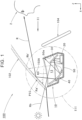
- FIG. 1 is a side sectional view showing an image projection device 10 mounted on a vehicle 100 according to the embodiment. Furthermore, FIG. 2 is an arrow view of FIG. 1 as viewed in a direction II.
- a direction indicated by X is a "forward direction” in the image projection device 10 (also a “forward direction” in a vehicle), a direction indicated by Y is a “leftward direction” that is orthogonal to the "forward direction”, and a direction indicated by Z is an “upward direction.”
- X is a "forward direction” in the image projection device 10 (also a “forward direction” in a vehicle)
- a direction indicated by Y is a “leftward direction” that is orthogonal to the "forward direction”
- a direction indicated by Z is an "upward direction.”
- the image projection device 10 is an in-vehicle head-up display, and is configured to, when disposed in a vehicle cabin of the vehicle 100, project a display image PIC onto a display area 102A of a front window 102 serving as an image display board.
- the display area 102A is set to be located in a lower area of the front window 102 and in an area in front of a steering wheel 104. This facilitates visual recognition by a driver 2 of the vehicle 100.
- FIG. 2 shows a state in which a vehicle speed (50 Km/h) is displayed together with a leftward arrow.
- the image projection device 10 is disposed to be located in front of the steering wheel 104 and near a lower side of the front window 102.
- the image projection device 10 includes: an image generation unit 20 that generates an image that is a source of the display image PIC; first and second reflecting mirrors 30, 40 that sequentially reflect light emitted from the image generation unit 20 to the display area 102A of the front window 102; a housing 50 that accommodates the image generation unit 20 and the first and second reflecting mirrors 30, 40; and a light-transmitting cover 60 attached to the housing 50.
- FIG. 3 is a detailed view of a portion III in FIG. 1 .
- the image generation unit 20 includes a liquid crystal panel 22, and is mounted on a lower wall portion of the housing 50 in a rear area of an internal space 12 of the housing 50 with the liquid crystal panel 22 facing upward.
- the image generation unit 20 is configured to generate an image that is a source of the display image PIC on the liquid crystal panel 22 by backlighting the liquid crystal panel 22 from below.
- the first reflecting mirror 30 is configured as a plane mirror and is disposed above the image generation unit 20.
- the first reflecting mirror 30 is configured to reflect radiated light from the image generation unit 20 in the forward direction, and is supported by the housing 50 while being positioned with respect to the image generation unit 20.
- the second reflecting mirror 40 is configured as a concave mirror and is disposed in front of the first reflecting mirror 30.
- the second reflecting mirror 40 is configured to reflect upward the radiated light from the image generation unit 20 that has been reflected by the first reflecting mirror 30. Note that this second reflecting mirror 40 is supported by the housing 50 via a rotation support member 42, thereby allowing angle adjustment for making the reflected light from the first reflecting mirror 30 correctly enter the display area 102A of the front window 102.
- the housing 50 is made of an opaque resin molded product and is open upward. This housing 50 has a configuration in which the entire area of an inner surface 50a of the housing 50 has a fine uneven structure (this will be described later).
- the light-transmitting cover 60 is constituted of a colorless and transparent resin panel curved downward, and is attached to an upper end opening portion of the housing 50 in a slightly upwardly inclined state in a rearward direction.
- the light-transmitting cover 60 allows reflected light from the second reflecting mirror 40 to enter the display area 102A, and also ensures dust-proofness of the internal space 12 of the housing 50.
- FIG. 4 is a detailed view of a portion IV in FIG. 3
- FIG. 5 is a detailed view of a portion V in FIG. 4 .
- a plurality of columnar protrusions 52 is formed on the inner surface 50a of the housing 50, and a second columnar protrusion 54 having a lower height than each of the plurality of columnar protrusions 52 is formed between the plurality of columnar protrusions 52.
- the plurality of columnar protrusions 52 is formed at a substantially constant pitch, and is all formed to have a substantially constant height.
- each of the columnar protrusions 52 has a conical shape similar to a cylinder, and a tip of the columnar protrusion 52 is formed in a hemispherical shape.
- a ratio between a pitch P between the plurality of columnar protrusions 52 and a height H1 of each of the plurality of columnar protrusions is set to a value of 1.5 or less.
- Each of a plurality of the second columnar protrusions 54 is located approximately at a center of a pair of the columnar protrusions 52 located on both front and rear sides of the second columnar protrusion 54, and a connecting portion 56 connected to one of the columnar protrusions 52 is formed in a lower area of the second columnar protrusion 54.
- Each of the second columnar protrusions 54 also has a conical shape similar to a cylinder, and a tip of the second columnar protrusion 54 is formed in a hemispherical shape.
- a diameter of each of the second columnar protrusions 54 is set to a smaller value than that of each of the columnar protrusions 52.
- FIG. 6 is an arrow view as viewed in a direction VI in FIG. 5 .
- the inner surface 50a of the housing 50 has a configuration in which a fine uneven structure shown in FIG. 5 is two-dimensionally expanded.
- the plurality of columnar protrusions 52 and the second columnar protrusions 54 having the cross-sectional shapes shown in FIG. 5 and disposed in a front-rear direction are formed in a plurality of rows at equal intervals in a left-right direction.
- the plurality of columnar protrusions 52 and the second columnar protrusions 54 are disposed so as to be shifted by a half pitch from mutually adjacent rows in the front-rear direction.
- the plurality of columnar protrusions 52 is disposed in a square diagonal lattice with the pitch P as shown by two-dotted broken lines in the figure, and the second columnar protrusion 54 is disposed approximately in a center of each lattice.
- the pitch P is a pitch along a diagonal line of the square diagonal lattice, and a pitch Po along sides of the square diagonal lattice has a smaller value than the pitch P.
- FIG. 5 shows optical paths of light incident from directions inclined at 45° and 75° with respect to the inner surface 50a of the housing 50.
- the light is reflected multiple times between the columnar protrusions 52 forming the mutually adjacent rows, and the light is also reflected multiple times between the second columnar protrusions 54.
- Intensity of the light that has reached the inner surface 50a of the housing 50 is attenuated each time it is reflected, so that a proportion of the light that is ultimately reflected toward the internal space 12 of the housing 50 is extremely small. Specifically, a ratio of the total amount of reflected light to the total amount of light incident on the inner surface 50a of the housing 50 is less than 5%.
- the fine uneven structure (namely, the structure in which the plurality of columnar protrusions 52 is formed, and the second columnar protrusion 54 having a lower height than each of the plurality of columnar protrusions 52 is formed between the plurality of columnar protrusions 52) of the inner surface 50a of the housing 50 can be formed by grain processing.
- etching the surface of the mold for forming the housing 50 it is possible to adopt a method in which etching is performed multiple times with an etching pattern shifted.
- An optical path R shown in FIGS. 1 and 3 is an original optical path when the driver 2 visually recognizes the display image PIC projected on the display area 102A of the front window 102 by the image projection device 10.
- Optical paths Ra, Rb shown in FIGS. 1 and 3 are optical paths other than the original optical path R, and are optical paths in which stray light may occur.
- the optical path Ra is an optical path when, out of light emitted from the image generation unit 20, light emitted from an end area of the liquid crystal panel 22 and sequentially reflected by the first and second reflecting mirrors 30, 40 reaches an upper end area of the rear wall portion of the inner surface 50a of the housing 50.
- the inner surface 50a of the housing 50 has the fine uneven structure as described above, the light that has reached the upper end area of the rear wall portion of the inner surface 50a is not specularly reflected. In this case, if specular reflection were to occur at the upper end area of the rear wall portion of the inner surface 50a, the light would reach a lower area of the display area 102A through the light-transmitting cover 60, as shown by an optical path Ra' indicated by a two-dotted broken line in the figure. As a result, an unnecessary image PICa' as shown in FIG. 2 is formed.
- the optical path Rb is an optical path when sunlight that has entered the internal space 12 of the housing 50 through the front window 102 and the light-transmitting cover 60 is reflected by the first reflecting mirror 30 and reaches a lower wall portion of the inner surface 50a of the housing 50.
- the inner surface 50a of the housing 50 Since the inner surface 50a of the housing 50 has the fine uneven structure as described above, the light that has reached the lower wall portion of the inner surface 50a is not specularly reflected. In this case, if specular reflection were to occur on the lower wall portion of the inner surface 50a, the light would reach an area near and above the display area 102A in the front window 102 through the light-transmitting cover 60, as shown by an optical path Rb' indicated by a two-dotted broken line in the figure. As a result, an unnecessary image PICb' as shown in FIG. 2 is formed.
- the image projection device 10 is configured to project the display image PIC on the front window 102 serving as an image display board, and the image generation unit 20 that generates the display image PIC is housed in a housing 50.
- the plurality of columnar protrusions 52 is formed on the inner surface 50a of the housing 50, and the second columnar protrusion 54 having a lower height than each of the plurality of columnar protrusions 52 is formed between the plurality of columnar protrusions 52. Therefore, the following effects can be obtained.
- the plurality of columnar protrusions 52 and the second columnar protrusions 54 are formed in a reaching area of the light. Therefore, the light that has reached the inner surface 50a can be reflected multiple times between the plurality of columnar protrusions 52 and between the plurality of columnar protrusions 52 and the second columnar protrusions 54, which can effectively attenuate intensity of the light. Accordingly, a proportion of the light that reaches the inner surface 50a of the housing 50 and then exits as reflected light to an external space of the housing 50 can be reduced.
- sunlight that has entered the vehicle cabin through the front window 102 enters the internal space 12 of the housing 50 through the light-transmitting cover 60, and may reach the inner surface 50a.
- the plurality of columnar protrusions 52 and the second columnar protrusions 54 are formed in the reaching area of the light, the light that has reached the inner surface 50a can be reflected multiple times between the plurality of columnar protrusions 52 and between the plurality of columnar protrusions 52 and the second columnar protrusions 54, which can effectively attenuate intensity of the light. Accordingly, the proportion of the light that reaches the inner surface 50a of the housing 50 and then exits as reflected light to an external space of the housing 50 can be reduced.
- the number of times that the emitted light from the image generation unit 20, sunlight, etc. that have reached the inner surface 50a of the housing 50 are reflected can be significantly increased. Accordingly, the proportion of the light that reaches the inner surface 50a of the housing 50 and then exits as reflected light to an external space of the housing 50 can be significantly reduced.
- the image projection device 10 configured to project the display image PIC on the front window 102, formation of unnecessary images due to stray light in the peripheral area of the display image PIC can be effectively suppressed.
- the generation of stray light can be suppressed without applying anti-reflection coating, etc. to the inner surface 50a of the housing 50, so that the cost of the image projection device 10 can be reduced.
- the ratio between the pitch P between the plurality of columnar protrusions 52 and the height H1 of each of the plurality of columnar protrusions 52 is set to a value of 1.5 or less, the number of times that the emitted light from the image generation unit 20, sunlight, etc. that have reached the inner surface 50a of the housing 50 are reflected between the plurality of columnar protrusions 52 and between the plurality of columnar protrusions 52 and the second columnar protrusions 54 can be sufficiently ensured. Accordingly, a light intensity attenuation effect can be sufficiently ensured. Accordingly, the proportion of the light that has reached the inner surface 50a of the housing 50 and then exits as reflected light to an external space of the housing 50 can be significantly reduced.
- the pitch between the plurality of columnar protrusions 52 is set to a value of 200 ⁇ m or less and the height of each of the plurality of columnar protrusions 52 is set to a value of 50 ⁇ m or more
- the number of times that the emitted light from the image generation unit 20, sunlight, etc. that have reached the inner surface 50a of the housing 50 are reflected between the plurality of columnar protrusions 52 and between the plurality of columnar protrusions 52 and the second columnar protrusions 54 can be sufficiently ensured. Accordingly, the light intensity attenuation effect can be sufficiently ensured. Accordingly, the proportion of the light that has reached the inner surface 50a of the housing 50 and then exits as reflected light to an external space of the housing 50 can be significantly reduced.
- the first and second reflecting mirrors 30, 40 are disposed in the internal space 12 of the housing 50 to sequentially reflect the light emitted from the image generation unit 20 to the display area 102A of the front window 102.
- the plurality of columnar protrusions 52 and the second columnar protrusions 54 are described as being formed in the entire area of the inner surface 50a of the housing 50, but a configuration is also possible in which the plurality of columnar protrusions 52 and the second columnar protrusions 54 are formed only in an area where light that causes stray light may enter.
- each of the plurality of columnar protrusions 52 and the second columnar protrusions 54 is described as having a conical shape similar to a cylinder, but a configuration in which the each of the plurality of columnar protrusions 52 and the second columnar protrusions 54 has another shape (for example, a pyramidal shape, etc. similar to a square columnar shape or a hexagonal columnar shape) is also possible.
- the image display board is described as being constituted by the front window 102, but it is also possible to constitute the image display board by a light-transmitting board, etc. disposed on a vehicle cabin side of the front window 102.
- the image projection device 10 is described as an in-vehicle head-up display, but the image projection device 10 can also be used for other purposes.
- FIG. 7 is a diagram similar to FIG. 5 , showing a main part of a housing 150 of an image projection device according to the modification.
- the housing 150 of the modification is also made of a resin molded product having the same shape as the housing 50 of the above embodiment, but is different from the above embodiment in that the housing 150 has a configuration in which carbon black 158 is dispersed.
- a reflectance of light reaching an inner surface 150a of the housing 150 can be further reduced due to the presence of the carbon black 158 than in the above embodiment, so that the generation of stray light can be further effectively suppressed.
- FIG. 8 is a diagram similar to FIG. 5 , showing a main part of a housing 250 of an image projection device according to the modification.
- the housing 250 of the modification is also made of a resin molded product similar to the housing 50 of the above embodiment, but a fine uneven structure formed on an inner surface 250a of the housing 250 is partly different from that of the above embodiment.
- a plurality of columnar protrusions 252 is formed on the inner surface 250a of the housing 250, and second columnar protrusions 254 having a lower height than each of the plurality of columnar protrusions 252 are formed between the plurality of columnar protrusions 252.
- the modification is different from the above embodiment in that two second columnar protrusions 254 are formed.
- the plurality of columnar protrusions 252 is formed with the same pitch P and the same height H1 as in the above embodiment.
- each of the second columnar protrusions 254 is formed to have a height that is approximately half the height H1 of each of the columnar protrusions 252.
- FIG. 9 is a diagram similar to FIG. 6 , showing a main part of a housing 350 of an image projection device according to the modification.
- the housing 350 of the modification is also made of a resin molded product similar to the housing 50 of the above embodiment, but a fine uneven structure formed on an inner surface 350a of the housing 350 is partly different from that of the above embodiment.
- a plurality of columnar protrusions 352 is formed on the inner surface 350a of the housing 350 at the same pitch P as in the above embodiment, and second columnar protrusions 354 having a lower height than each of the plurality of columnar protrusions 352 are formed between the plurality of columnar protrusions 352.
- the modification is different from the above embodiment in that two second columnar protrusions 354 are formed.
- the plurality of columnar protrusions 352 is disposed in a square diagonal lattice with the pitch P, and two second columnar protrusions 354 are disposed in each lattice.
- two second columnar protrusions 354 are connected to each of the plurality of columnar protrusions 352 via connecting portions 356, and in this case, the connecting portions 356 extend in a direction inclined with respect to the front-rear direction.
- a configuration can be made in which the plurality of columnar protrusions 352 and the second columnar protrusions 354 are two-dimensionally disposed at a higher density.
Landscapes
- Physics & Mathematics (AREA)
- Engineering & Computer Science (AREA)
- General Physics & Mathematics (AREA)
- Chemical & Material Sciences (AREA)
- Combustion & Propulsion (AREA)
- Transportation (AREA)
- Mechanical Engineering (AREA)
- Optics & Photonics (AREA)
- Instrument Panels (AREA)
- Projection Apparatus (AREA)
Abstract
Description
- The present invention relates to an image projection device configured to project a display image on an image display board.
- Conventionally, an image projection device has been known as an in-vehicle image projection device. The image projection device is configured to, when disposed in a vehicle cabin, project a display image on an image display board such as a front window or a light-transmitting board disposed on a vehicle cabin side of the front window.
- This image projection device has a configuration including an image generation unit that generates a display image and a housing that accommodates the image generation unit, as described in, for example, "Patent Document 1".
- Patent Document 1:
Japanese Unexamined Patent Application Publication No. 2021-890 JP 2021-890 A - In such an image projection device, a part of the light emitted from the image generation unit may be reflected on the inner surface of the housing, resulting in stray light reaching an image display board. Then, the stray light that has reached the image display board may cause unintended and unnecessary images to be formed in the peripheral area of a display image.
- Furthermore, sunlight that has entered the vehicle cabin through the front window, etc. may enter the internal space of the housing and become stray light by being reflected on the inner surface of the housing.
- Note that such a problem can similarly occur in image projection devices other than in-vehicle image projection devices.
- The present invention has been made in view of the above circumstances, and it is an object of the present invention to provide an image projection device that is configured to project a display image on an image display board, and that allows effectively suppressing the formation of unnecessary images in the peripheral area of the display image due to the generation of stray light.
- The present invention aims to achieve the above object by devising a configuration of a housing.
- That is, an image projection device according to the present invention configured to project a display image on an image display board is characterized in that: the image projection device includes an image generation unit that generates the display image, and a housing that accommodates the image generation unit; a plurality of columnar protrusions is formed on an inner surface of the housing; and a second columnar protrusion having a lower height than each of the plurality of the columnar protrusions is formed between the plurality of the columnar protrusions.
- The above "image projection device" is not particularly limited in its specific use as long as the device is configured to project the display image on the image display board. For example, applications such as an in-vehicle head-up display can be adopted.
- The above "image display board" is not particularly limited in its specific configuration as long as the board is configured to project the display image. For example, the front window of a vehicle or a light-transmitting board, etc. disposed on a vehicle cabin side of the front window can be adopted.
- The above "plurality of columnar protrusions" is formed on the inner surface of the housing, but a specific area where the columnar protrusions are formed is not particularly limited. The columnar protrusions may be formed in the entire area of the inner surface of the housing or in a partial area of the inner surface.
- A specific height, a cross-sectional shape, etc. of each of the "plurality of columnar protrusions" are not particularly limited. For example, columnar protrusions formed in a columnar shape or a prismatic shape can be adopted.
- The "second columnar protrusion" is not particularly limited in its specific height, cross-sectional shape, etc., as long as the second columnar protrusion is formed to have a lower height than each of the plurality of the columnar protrusions.
- The image projection device according to the present invention is configured to project the display image on the image display board, and the image generation unit that generates the display image is housed in the housing. The plurality of the columnar protrusions is formed on the inner surface of the housing, and the second columnar protrusion having a lower height than each of the plurality of the columnar protrusions is formed between the plurality of the columnar protrusions. Therefore, the following effects can be obtained.
- That is, even when a part of emitted light from the image generation unit reaches the inner surface of the housing, the plurality of the columnar protrusions and the second columnar protrusions are formed in a reaching area of the light. Therefore, the light that has reached the inner surface can be reflected multiple times between the plurality of the columnar protrusions and between the plurality of the columnar protrusions and the second columnar protrusions, which can effectively attenuate intensity of the light. Accordingly, a proportion of the light that reaches the inner surface of the housing and then exits as reflected light to an external space of the housing can be reduced.
- Furthermore, for example, in an in-vehicle image projection device, even when sunlight that has entered the vehicle cabin through the front window, etc. enters the internal space of the housing and reaches the inner surface of the housing, with a configuration in which the plurality of the columnar protrusions and the second columnar protrusions are formed in the reaching area of the light, the light that has reached the inner surface can be reflected multiple times between the plurality of columnar protrusions and between the plurality of the columnar protrusions and the second columnar protrusions, which can effectively attenuate intensity of the light. Accordingly, the proportion of the light that reaches the inner surface of the housing and then exits as reflected light to an external space of the housing can be reduced.
- Therefore, it is possible to effectively suppress the light reflected on the inner surface of the housing from becoming stray light and reaching the image display board. This makes it possible to effectively suppress the formation of unnecessary images due to stray light in the peripheral area of the display image.
- Moreover, as described above, by adopting the configuration in which a plurality of the second columnar protrusions is formed together with the plurality of the columnar protrusions on the inner surface of the housing, as compared to a configuration in which only the plurality of the columnar protrusions is formed on the inner surface of the housing, the number of times that the emitted light from the image generation unit, sunlight, etc. that have reached the inner surface of the housing are reflected can be significantly increased. Accordingly, the proportion of the light that reaches the inner surface of the housing and then exits as reflected light to an external space of the housing can be significantly reduced.
- In this way, according to the present invention, in the image projection device configured to project the display image on the image display board, formation of unnecessary images in the peripheral area of the display image due to the generation of stray light can be effectively suppressed.
- Moreover, according to the present invention, the generation of stray light can be suppressed without applying anti-reflection coating, etc. to the inner surface of the housing, so that the cost of the image projection device can be reduced.
- Furthermore, in the above configuration, when a ratio between a pitch between the plurality of the columnar protrusions and a height of each of the plurality of the columnar protrusions is set to a value of 1.5 or less, the number of times that the emitted light from the image generation unit, sunlight, etc. that have reached the inner surface of the housing are reflected between the plurality of the columnar protrusions and between the plurality of the columnar protrusions and the second columnar protrusions can be sufficiently ensured. Accordingly, a light intensity attenuation effect can be sufficiently ensured. Accordingly, the proportion of the light that reaches the inner surface of the housing and then exits as reflected light to an external space of the housing can be significantly reduced.
- Furthermore, in the above configuration, when the pitch between the plurality of the columnar protrusions is set to a value of 200 µm or less and the height of each of the plurality of the columnar protrusions is set to a value of 50 µm or more, the number of times that the emitted light from the image generation unit, sunlight, etc. that have reached the inner surface of the housing are reflected between the plurality of the columnar protrusions and between the plurality of the columnar protrusions and the second columnar protrusions can be sufficiently ensured. Accordingly, a light intensity attenuation effect can be sufficiently ensured. Accordingly, the proportion of the light that reaches the inner surface of the housing and then exits as reflected light to an external space of the housing can be significantly reduced.
- Furthermore, in the above configuration, when the housing is made of a resin molded product in which carbon black is dispersed, a reflectance of light reaching the inner surface of the housing can be reduced due to the presence of carbon black. Therefore, the generation of stray light can be further effectively suppressed.
- Furthermore, as a configuration of the image projection device, when a reflecting mirror that reflects light emitted from the image generation unit toward the image display board is disposed in the housing, it is possible to easily guide the emitted light from the image generation unit to the image display board. On the other hand, with such a configuration, there is a risk that stray light may be generated due to the light reflected by the reflecting mirror reaching the inner surface of the housing, so that adopting the configuration of the present invention is particularly effective.
-
- [
FIG.1] FIG. 1 is a side sectional view showing an image projection device mounted on a vehicle according to an embodiment of the present invention. - [
FIG. 2] FIG.2 is an arrow view as viewed in a direction II inFIG. 1 . - [
FIG. 3] FIG. 3 is a detailed view of a portion III inFIG. 1 . - [
FIG. 4] FIG. 4 is a detailed view of a portion IV inFIG. 3 . - [
FIG. 5] FIG. 5 is a detailed view of a portion V inFIG. 4 . - [
FIG. 6] FIG. 6 is an arrow view as viewed in a direction VI inFIG. 5 . - [
FIG. 7] FIG. 7 is a diagram similar toFIG. 5 , showing a first modification of the above embodiment. - [
FIG. 8] FIG. 8 is a diagram similar toFIG. 5 , showing a second modification of the above embodiment. - [
FIG. 9] FIG. 9 is a diagram similar toFIG. 6 , showing a third modification of the above embodiment. - An embodiment of the present invention will be described below with reference to the drawings.
-
FIG. 1 is a side sectional view showing animage projection device 10 mounted on avehicle 100 according to the embodiment. Furthermore,FIG. 2 is an arrow view ofFIG. 1 as viewed in a direction II. - In these figures, a direction indicated by X is a "forward direction" in the image projection device 10 (also a "forward direction" in a vehicle), a direction indicated by Y is a "leftward direction" that is orthogonal to the "forward direction", and a direction indicated by Z is an "upward direction." The same applies to figures other than these figures.
- As shown in
FIGS. 1 and2 , theimage projection device 10 according to the embodiment is an in-vehicle head-up display, and is configured to, when disposed in a vehicle cabin of thevehicle 100, project a display image PIC onto adisplay area 102A of afront window 102 serving as an image display board. - The
display area 102A is set to be located in a lower area of thefront window 102 and in an area in front of asteering wheel 104. This facilitates visual recognition by adriver 2 of thevehicle 100. Note that, as a specific example of the display image PIC,FIG. 2 shows a state in which a vehicle speed (50 Km/h) is displayed together with a leftward arrow. - The
image projection device 10 is disposed to be located in front of thesteering wheel 104 and near a lower side of thefront window 102. - As shown in
FIG. 1 , theimage projection device 10 includes: animage generation unit 20 that generates an image that is a source of the display image PIC; first and second reflectingmirrors image generation unit 20 to thedisplay area 102A of thefront window 102; ahousing 50 that accommodates theimage generation unit 20 and the first and second reflectingmirrors cover 60 attached to thehousing 50. -
FIG. 3 is a detailed view of a portion III inFIG. 1 . - As shown in
FIG. 3 , theimage generation unit 20 includes aliquid crystal panel 22, and is mounted on a lower wall portion of thehousing 50 in a rear area of aninternal space 12 of thehousing 50 with theliquid crystal panel 22 facing upward. Theimage generation unit 20 is configured to generate an image that is a source of the display image PIC on theliquid crystal panel 22 by backlighting theliquid crystal panel 22 from below. - The first reflecting
mirror 30 is configured as a plane mirror and is disposed above theimage generation unit 20. The first reflectingmirror 30 is configured to reflect radiated light from theimage generation unit 20 in the forward direction, and is supported by thehousing 50 while being positioned with respect to theimage generation unit 20. - The second reflecting
mirror 40 is configured as a concave mirror and is disposed in front of the first reflectingmirror 30. The second reflectingmirror 40 is configured to reflect upward the radiated light from theimage generation unit 20 that has been reflected by the first reflectingmirror 30. Note that this second reflectingmirror 40 is supported by thehousing 50 via arotation support member 42, thereby allowing angle adjustment for making the reflected light from the first reflectingmirror 30 correctly enter thedisplay area 102A of thefront window 102. - The
housing 50 is made of an opaque resin molded product and is open upward. Thishousing 50 has a configuration in which the entire area of aninner surface 50a of thehousing 50 has a fine uneven structure (this will be described later). - The light-transmitting
cover 60 is constituted of a colorless and transparent resin panel curved downward, and is attached to an upper end opening portion of thehousing 50 in a slightly upwardly inclined state in a rearward direction. The light-transmittingcover 60 allows reflected light from the second reflectingmirror 40 to enter thedisplay area 102A, and also ensures dust-proofness of theinternal space 12 of thehousing 50. -
FIG. 4 is a detailed view of a portion IV inFIG. 3 , andFIG. 5 is a detailed view of a portion V inFIG. 4 . - As shown in
FIGS. 4 and5 , a plurality ofcolumnar protrusions 52 is formed on theinner surface 50a of thehousing 50, and a secondcolumnar protrusion 54 having a lower height than each of the plurality ofcolumnar protrusions 52 is formed between the plurality ofcolumnar protrusions 52. - The plurality of
columnar protrusions 52 is formed at a substantially constant pitch, and is all formed to have a substantially constant height. In this case, each of thecolumnar protrusions 52 has a conical shape similar to a cylinder, and a tip of thecolumnar protrusion 52 is formed in a hemispherical shape. - A ratio between a pitch P between the plurality of
columnar protrusions 52 and a height H1 of each of the plurality of columnar protrusions is set to a value of 1.5 or less. Specifically, the pitch P is set to a value P = approximately 70 to 200 µm, and the height H1 is set to a value H1 = approximately 50 to 140 µm. - Each of a plurality of the second
columnar protrusions 54 is located approximately at a center of a pair of thecolumnar protrusions 52 located on both front and rear sides of the secondcolumnar protrusion 54, and a connectingportion 56 connected to one of thecolumnar protrusions 52 is formed in a lower area of the secondcolumnar protrusion 54. - Each of the second
columnar protrusions 54 also has a conical shape similar to a cylinder, and a tip of the secondcolumnar protrusion 54 is formed in a hemispherical shape. A height H2 of each of the secondcolumnar protrusions 54 is set to a value H2 = approximately 0.4 to 0.8 × H1 with respect to the height H1 of each of thecolumnar protrusions 52. Furthermore, a diameter of each of the secondcolumnar protrusions 54 is set to a smaller value than that of each of thecolumnar protrusions 52. -
FIG. 6 is an arrow view as viewed in a direction VI inFIG. 5 . - As shown in
FIG. 6 , theinner surface 50a of thehousing 50 has a configuration in which a fine uneven structure shown inFIG. 5 is two-dimensionally expanded. - That is, the plurality of
columnar protrusions 52 and the secondcolumnar protrusions 54 having the cross-sectional shapes shown inFIG. 5 and disposed in a front-rear direction are formed in a plurality of rows at equal intervals in a left-right direction. In this case, the plurality ofcolumnar protrusions 52 and the secondcolumnar protrusions 54 are disposed so as to be shifted by a half pitch from mutually adjacent rows in the front-rear direction. As a result, the plurality ofcolumnar protrusions 52 is disposed in a square diagonal lattice with the pitch P as shown by two-dotted broken lines in the figure, and the secondcolumnar protrusion 54 is disposed approximately in a center of each lattice. - Note that the pitch P is a pitch along a diagonal line of the square diagonal lattice, and a pitch Po along sides of the square diagonal lattice has a smaller value than the pitch P.
- As shown in
FIG. 4 , light that has reached theinner surface 50a of theinternal space 12 of thehousing 50 is absorbed or diffusely reflected by theinner surface 50a without being specularly reflected. This is because theinner surface 50a of thehousing 50 has the above-mentioned fine uneven structure. - That is, as shown in
FIG. 5 , the light that has reached theinner surface 50a of thehousing 50 is reflected multiple times between thecolumnar protrusions 52 and the secondcolumnar protrusions 54 that are adjacent to each other. Note thatFIG. 5 shows optical paths of light incident from directions inclined at 45° and 75° with respect to theinner surface 50a of thehousing 50. - Furthermore, as shown in
FIG. 6 , since the fine uneven structure is expanded two-dimensionally, the light is reflected multiple times between thecolumnar protrusions 52 forming the mutually adjacent rows, and the light is also reflected multiple times between the secondcolumnar protrusions 54. - Intensity of the light that has reached the
inner surface 50a of thehousing 50 is attenuated each time it is reflected, so that a proportion of the light that is ultimately reflected toward theinternal space 12 of thehousing 50 is extremely small. Specifically, a ratio of the total amount of reflected light to the total amount of light incident on theinner surface 50a of thehousing 50 is less than 5%. - Note that the fine uneven structure (namely, the structure in which the plurality of
columnar protrusions 52 is formed, and the secondcolumnar protrusion 54 having a lower height than each of the plurality ofcolumnar protrusions 52 is formed between the plurality of columnar protrusions 52) of theinner surface 50a of thehousing 50 can be formed by grain processing. In this case, it is possible to form a transferred shape of the fine uneven structure by performing etching, laser processing, etc. on a surface of a mold for forming thehousing 50. When etching the surface of the mold for forming thehousing 50, it is possible to adopt a method in which etching is performed multiple times with an etching pattern shifted. - Next, optical functions of the
image projection device 10 will be explained. - An optical path R shown in
FIGS. 1 and3 is an original optical path when thedriver 2 visually recognizes the display image PIC projected on thedisplay area 102A of thefront window 102 by theimage projection device 10. - Optical paths Ra, Rb shown in
FIGS. 1 and3 are optical paths other than the original optical path R, and are optical paths in which stray light may occur. - The optical path Ra is an optical path when, out of light emitted from the
image generation unit 20, light emitted from an end area of theliquid crystal panel 22 and sequentially reflected by the first and second reflectingmirrors inner surface 50a of thehousing 50. - Since the
inner surface 50a of thehousing 50 has the fine uneven structure as described above, the light that has reached the upper end area of the rear wall portion of theinner surface 50a is not specularly reflected. In this case, if specular reflection were to occur at the upper end area of the rear wall portion of theinner surface 50a, the light would reach a lower area of thedisplay area 102A through the light-transmittingcover 60, as shown by an optical path Ra' indicated by a two-dotted broken line in the figure. As a result, an unnecessary image PICa' as shown inFIG. 2 is formed. - On the other hand, the optical path Rb is an optical path when sunlight that has entered the
internal space 12 of thehousing 50 through thefront window 102 and the light-transmittingcover 60 is reflected by the first reflectingmirror 30 and reaches a lower wall portion of theinner surface 50a of thehousing 50. - Since the
inner surface 50a of thehousing 50 has the fine uneven structure as described above, the light that has reached the lower wall portion of theinner surface 50a is not specularly reflected. In this case, if specular reflection were to occur on the lower wall portion of theinner surface 50a, the light would reach an area near and above thedisplay area 102A in thefront window 102 through the light-transmittingcover 60, as shown by an optical path Rb' indicated by a two-dotted broken line in the figure. As a result, an unnecessary image PICb' as shown inFIG. 2 is formed. - Next, effects of the embodiment will be explained.
- The
image projection device 10 according to the embodiment is configured to project the display image PIC on thefront window 102 serving as an image display board, and theimage generation unit 20 that generates the display image PIC is housed in ahousing 50. The plurality ofcolumnar protrusions 52 is formed on theinner surface 50a of thehousing 50, and the secondcolumnar protrusion 54 having a lower height than each of the plurality ofcolumnar protrusions 52 is formed between the plurality ofcolumnar protrusions 52. Therefore, the following effects can be obtained. - That is, even when a part of emitted light from the
image generation unit 20 reaches theinner surface 50a of thehousing 50, the plurality ofcolumnar protrusions 52 and the secondcolumnar protrusions 54 are formed in a reaching area of the light. Therefore, the light that has reached theinner surface 50a can be reflected multiple times between the plurality ofcolumnar protrusions 52 and between the plurality ofcolumnar protrusions 52 and the secondcolumnar protrusions 54, which can effectively attenuate intensity of the light. Accordingly, a proportion of the light that reaches theinner surface 50a of thehousing 50 and then exits as reflected light to an external space of thehousing 50 can be reduced. - Furthermore, in the
image projection device 10 according to the embodiment, sunlight that has entered the vehicle cabin through thefront window 102 enters theinternal space 12 of thehousing 50 through the light-transmittingcover 60, and may reach theinner surface 50a. However, since the plurality ofcolumnar protrusions 52 and the secondcolumnar protrusions 54 are formed in the reaching area of the light, the light that has reached theinner surface 50a can be reflected multiple times between the plurality ofcolumnar protrusions 52 and between the plurality ofcolumnar protrusions 52 and the secondcolumnar protrusions 54, which can effectively attenuate intensity of the light. Accordingly, the proportion of the light that reaches theinner surface 50a of thehousing 50 and then exits as reflected light to an external space of thehousing 50 can be reduced. - Therefore, it is possible to effectively suppress the light reflected from the
inner surface 50a of thehousing 50 from becoming stray light and reaching thedisplay area 102A of thefront window 102 through the light-transmittingcover 60. This makes it possible to effectively suppress formation of unnecessary images (see the images PICa', PICb' shown inFIG. 2 ) due to stray light in a peripheral area of the display image PIC. - Moreover, as in the embodiment, by adopting a configuration in which the plurality of the second
columnar protrusions 54 is formed together with the plurality ofcolumnar protrusions 52 on theinner surface 50a of thehousing 50, as compared to a configuration in which only the plurality ofcolumnar protrusions 52 is formed on theinner surface 50a of thehousing 50, the number of times that the emitted light from theimage generation unit 20, sunlight, etc. that have reached theinner surface 50a of thehousing 50 are reflected can be significantly increased. Accordingly, the proportion of the light that reaches theinner surface 50a of thehousing 50 and then exits as reflected light to an external space of thehousing 50 can be significantly reduced. - According to the embodiment, in the
image projection device 10 configured to project the display image PIC on thefront window 102, formation of unnecessary images due to stray light in the peripheral area of the display image PIC can be effectively suppressed. - Moreover, according to the embodiment, the generation of stray light can be suppressed without applying anti-reflection coating, etc. to the
inner surface 50a of thehousing 50, so that the cost of theimage projection device 10 can be reduced. - In this case, in the embodiment, since the ratio between the pitch P between the plurality of
columnar protrusions 52 and the height H1 of each of the plurality ofcolumnar protrusions 52 is set to a value of 1.5 or less, the number of times that the emitted light from theimage generation unit 20, sunlight, etc. that have reached theinner surface 50a of thehousing 50 are reflected between the plurality ofcolumnar protrusions 52 and between the plurality ofcolumnar protrusions 52 and the secondcolumnar protrusions 54 can be sufficiently ensured. Accordingly, a light intensity attenuation effect can be sufficiently ensured. Accordingly, the proportion of the light that has reached theinner surface 50a of thehousing 50 and then exits as reflected light to an external space of thehousing 50 can be significantly reduced. - Furthermore, in the embodiment, since the pitch between the plurality of
columnar protrusions 52 is set to a value of 200 µm or less and the height of each of the plurality ofcolumnar protrusions 52 is set to a value of 50 µm or more, the number of times that the emitted light from theimage generation unit 20, sunlight, etc. that have reached theinner surface 50a of thehousing 50 are reflected between the plurality ofcolumnar protrusions 52 and between the plurality ofcolumnar protrusions 52 and the secondcolumnar protrusions 54 can be sufficiently ensured. Accordingly, the light intensity attenuation effect can be sufficiently ensured. Accordingly, the proportion of the light that has reached theinner surface 50a of thehousing 50 and then exits as reflected light to an external space of thehousing 50 can be significantly reduced. - Furthermore, in the embodiment, the first and second reflecting
mirrors internal space 12 of thehousing 50 to sequentially reflect the light emitted from theimage generation unit 20 to thedisplay area 102A of thefront window 102. This makes it possible to easily guide the emitted light from theimage generation unit 20 to thedisplay area 102A of thefront window 102. In this case, there is a risk that stray light may be generated due to the light reflected by the first and second reflectingmirrors inner surface 50a of thehousing 50, so that adopting the configuration of the embodiment is particularly effective. - In the above embodiment, the plurality of
columnar protrusions 52 and the secondcolumnar protrusions 54 are described as being formed in the entire area of theinner surface 50a of thehousing 50, but a configuration is also possible in which the plurality ofcolumnar protrusions 52 and the secondcolumnar protrusions 54 are formed only in an area where light that causes stray light may enter. - Although the above embodiment is described as including the first and second reflecting
mirrors - In the above embodiment, each of the plurality of
columnar protrusions 52 and the secondcolumnar protrusions 54 is described as having a conical shape similar to a cylinder, but a configuration in which the each of the plurality ofcolumnar protrusions 52 and the secondcolumnar protrusions 54 has another shape (for example, a pyramidal shape, etc. similar to a square columnar shape or a hexagonal columnar shape) is also possible. - In the above embodiment, the image display board is described as being constituted by the
front window 102, but it is also possible to constitute the image display board by a light-transmitting board, etc. disposed on a vehicle cabin side of thefront window 102. - In the embodiment described above, the
image projection device 10 is described as an in-vehicle head-up display, but theimage projection device 10 can also be used for other purposes. - Next, modifications of the above embodiment will be described.
- First, a first modification of the above embodiment will be described.
-
FIG. 7 is a diagram similar toFIG. 5 , showing a main part of ahousing 150 of an image projection device according to the modification. - As shown in
FIG. 7 , thehousing 150 of the modification is also made of a resin molded product having the same shape as thehousing 50 of the above embodiment, but is different from the above embodiment in that thehousing 150 has a configuration in whichcarbon black 158 is dispersed. - By adopting the configuration of this modification, a reflectance of light reaching an
inner surface 150a of thehousing 150 can be further reduced due to the presence of thecarbon black 158 than in the above embodiment, so that the generation of stray light can be further effectively suppressed. - Next, a second modification of the above embodiment will be described.
-
FIG. 8 is a diagram similar toFIG. 5 , showing a main part of ahousing 250 of an image projection device according to the modification. - As shown in
FIG. 8 , thehousing 250 of the modification is also made of a resin molded product similar to thehousing 50 of the above embodiment, but a fine uneven structure formed on aninner surface 250a of thehousing 250 is partly different from that of the above embodiment. - That is, in the modification as well, a plurality of
columnar protrusions 252 is formed on theinner surface 250a of thehousing 250, and secondcolumnar protrusions 254 having a lower height than each of the plurality ofcolumnar protrusions 252 are formed between the plurality ofcolumnar protrusions 252. The modification is different from the above embodiment in that two secondcolumnar protrusions 254 are formed. - In this case, the plurality of
columnar protrusions 252 is formed with the same pitch P and the same height H1 as in the above embodiment. On the other hand, each of the secondcolumnar protrusions 254 is formed to have a height that is approximately half the height H1 of each of thecolumnar protrusions 252. - By adopting the configuration of the modification, light that has reached the
inner surface 250a of thehousing 250 can be more reflected, and the attenuation effect of light intensity can be enhanced, so that the generation of stray light can be further effectively suppressed. - Next, a third modification of the above embodiment will be described.
-
FIG. 9 is a diagram similar toFIG. 6 , showing a main part of ahousing 350 of an image projection device according to the modification. - As shown in
FIG. 9 , thehousing 350 of the modification is also made of a resin molded product similar to thehousing 50 of the above embodiment, but a fine uneven structure formed on aninner surface 350a of thehousing 350 is partly different from that of the above embodiment. - That is, also in this modification, a plurality of
columnar protrusions 352 is formed on theinner surface 350a of thehousing 350 at the same pitch P as in the above embodiment, and secondcolumnar protrusions 354 having a lower height than each of the plurality ofcolumnar protrusions 352 are formed between the plurality ofcolumnar protrusions 352. The modification is different from the above embodiment in that two secondcolumnar protrusions 354 are formed. - In this case, the plurality of
columnar protrusions 352 is disposed in a square diagonal lattice with the pitch P, and two secondcolumnar protrusions 354 are disposed in each lattice. - Furthermore, two second
columnar protrusions 354 are connected to each of the plurality ofcolumnar protrusions 352 via connectingportions 356, and in this case, the connectingportions 356 extend in a direction inclined with respect to the front-rear direction. - By adopting the configuration of the modification, a configuration can be made in which the plurality of
columnar protrusions 352 and the secondcolumnar protrusions 354 are two-dimensionally disposed at a higher density. With the configuration, light that has reached theinner surface 350a of thehousing 350 can be more reflected, and the attenuation effect of light intensity can be enhanced, so that the generation of stray light can be further effectively suppressed. - Note that the numerical values shown as specifications in the above embodiment and modifications thereof are merely examples, and it goes without saying that these may be set to different values as appropriate.
- Furthermore, the present invention is not limited to the configurations described in the above embodiment and modifications thereof, and configurations with various other changes can be adopted.
- This international application claims priority to
Japanese Patent Application No. 2021-135209, which is a Japanese patent application filed on August 20, 2021 Japanese Patent Application No. 2021-135209 - The above descriptions of specific forms of the present invention have been presented for purposes of illustration. They are not intended to be exhaustive or to limit the present invention to the precise forms described. It will be obvious to those skilled in the art that many modifications and changes are possible in light of the above descriptions.
-
- 2 Driver
- 10 Image projection device
- 12 Internal space
- 20 Image generation unit
- 22 Liquid crystal panel
- 30 First reflecting mirror
- 40 Second reflecting mirror
- 42 Rotation support member
- 50, 150, 250, 350 Housing
- 50a, 150a, 250a, 350a Inner surface
- 52, 252, 352 Columnar protrusion
- 54, 254, 354 Second columnar protrusion
- 56, 356 Connecting portion
- 60 Light-transmitting cover
- 100 Vehicle
- 102 Front window (image display board)
- 102A Display area
- 104 Steering wheel
- 158 Carbon black
- H1, H2 Height
- P, Po Pitch
- PIC Display image
- R, Ra, Rb Optical path
Claims (5)
- An image projection device configured to project a display image on an image display board, the image projection device characterized in that:the image projection device includes an image generation unit that generates the display image, and a housing that accommodates the image generation unit;a plurality of columnar protrusions is formed on an inner surface of the housing; anda second columnar protrusion having a lower height than each of the plurality of the columnar protrusions is formed between the plurality of the columnar protrusions.
- The image projection device according to claim 1, characterized in that a ratio between a pitch between the plurality of the columnar protrusions and a height of each of the plurality of the columnar protrusions is set to a value of 1.5 or less.
- The image projection device according to claim 1 or 2, characterized in that:a pitch between the plurality of the columnar protrusions is set to a value of 200 µm or less; anda height of each of the plurality of the columnar protrusions is set to a value of 50 µm or more.
- The image projection device according to claim 1 or 2, characterized in that the housing is made of a resin molded product in which carbon black is dispersed.
- The image projection device according to claim 1 or 2, characterized in that a reflecting mirror that reflects light emitted from the image generation unit toward the image display board is disposed in the housing.
Applications Claiming Priority (2)
| Application Number | Priority Date | Filing Date | Title |
|---|---|---|---|
| JP2021135209A JP7660462B2 (en) | 2021-08-20 | 2021-08-20 | Image projection device |
| PCT/JP2022/030409 WO2023022070A1 (en) | 2021-08-20 | 2022-08-09 | Image irradiation device |
Publications (2)
| Publication Number | Publication Date |
|---|---|
| EP4390507A1 true EP4390507A1 (en) | 2024-06-26 |
| EP4390507A4 EP4390507A4 (en) | 2024-12-25 |
Family
ID=85240750
Family Applications (1)
| Application Number | Title | Priority Date | Filing Date |
|---|---|---|---|
| EP22858391.0A Withdrawn EP4390507A4 (en) | 2021-08-20 | 2022-08-09 | Image irradiation device |
Country Status (5)
| Country | Link |
|---|---|
| US (1) | US20250216755A1 (en) |
| EP (1) | EP4390507A4 (en) |
| JP (1) | JP7660462B2 (en) |
| CN (1) | CN117836697A (en) |
| WO (1) | WO2023022070A1 (en) |
Family Cites Families (9)
| Publication number | Priority date | Publication date | Assignee | Title |
|---|---|---|---|---|
| JP6153078B2 (en) | 2013-09-24 | 2017-06-28 | 日本精機株式会社 | Vehicle display device |
| JP6254988B2 (en) | 2015-10-21 | 2017-12-27 | 矢崎総業株式会社 | Head-up display device |
| JP6833450B2 (en) * | 2016-10-27 | 2021-02-24 | 旭化成株式会社 | Head-up display device |
| GB2567238B (en) | 2017-10-09 | 2020-01-08 | Surrey Nanosystems Ltd | Paint with low light reflectivity |
| JP7423202B2 (en) | 2018-07-30 | 2024-01-29 | キヤノン株式会社 | Resin products, resin product manufacturing methods, interchangeable lenses, and optical equipment |
| JP2020056872A (en) | 2018-10-01 | 2020-04-09 | キヤノン電子株式会社 | Light control device, and camera |
| JP7452955B2 (en) | 2019-06-20 | 2024-03-19 | 株式会社小糸製作所 | heads up display system |
| JP7532132B2 (en) | 2019-09-30 | 2024-08-13 | キヤノン株式会社 | Optical member, optical device, imaging device, and method for manufacturing optical member |
| JP2021135209A (en) | 2020-02-27 | 2021-09-13 | Drone Pilot Agency株式会社 | Device and method for determining crack region and program for the same |
-
2021
- 2021-08-20 JP JP2021135209A patent/JP7660462B2/en active Active
-
2022
- 2022-08-09 WO PCT/JP2022/030409 patent/WO2023022070A1/en not_active Ceased
- 2022-08-09 US US18/683,958 patent/US20250216755A1/en active Pending
- 2022-08-09 EP EP22858391.0A patent/EP4390507A4/en not_active Withdrawn
- 2022-08-09 CN CN202280056281.5A patent/CN117836697A/en active Pending
Also Published As
| Publication number | Publication date |
|---|---|
| WO2023022070A1 (en) | 2023-02-23 |
| US20250216755A1 (en) | 2025-07-03 |
| EP4390507A4 (en) | 2024-12-25 |
| JP7660462B2 (en) | 2025-04-11 |
| CN117836697A (en) | 2024-04-05 |
| JP2023029107A (en) | 2023-03-03 |
Similar Documents
| Publication | Publication Date | Title |
|---|---|---|
| US7686463B2 (en) | Viewing-angle control sheet | |
| US11448878B2 (en) | Head up display | |
| WO2020183844A1 (en) | Head-up display device | |
| WO2022210362A1 (en) | Image projection device | |
| US20250216755A1 (en) | Image projection device | |
| US11867902B2 (en) | Display device, head-up display, moving body, and light guide panel | |
| US5825339A (en) | Display apparatus for automobiles | |
| CN112444995B (en) | Display device for vehicle | |
| CN114660817B (en) | Head-up display, vehicle and head-up display method | |
| US11754775B2 (en) | Light emitting device and light guiding member | |
| WO2020241218A1 (en) | Projection device and head-up display | |
| JP7643808B2 (en) | Display device | |
| JP2024007196A (en) | Vehicle display device | |
| EP4163713A1 (en) | Display device, head-up display, and mobile object | |
| CN113302077A (en) | Head-up display device | |
| JP2020042287A (en) | Head-up display device | |
| US20250035925A1 (en) | Head-Up Display Device | |
| CN115047621B (en) | Vehicle body structure with head-up display | |
| JP7839546B2 (en) | Head-up displays and display devices | |
| CN112444999A (en) | Display device for vehicle | |
| CN121232349A (en) | Light guide plate and display device | |
| JP2012081780A (en) | Head-up display lamp | |
| EP4163712A1 (en) | Display device, head-up display, and mobile object | |
| WO2023188935A1 (en) | Display apparatus | |
| KR20260048335A (en) | Display devices and means of transport |
Legal Events
| Date | Code | Title | Description |
|---|---|---|---|
| STAA | Information on the status of an ep patent application or granted ep patent |
Free format text: STATUS: THE INTERNATIONAL PUBLICATION HAS BEEN MADE |
|
| PUAI | Public reference made under article 153(3) epc to a published international application that has entered the european phase |
Free format text: ORIGINAL CODE: 0009012 |
|
| STAA | Information on the status of an ep patent application or granted ep patent |
Free format text: STATUS: REQUEST FOR EXAMINATION WAS MADE |
|
| 17P | Request for examination filed |
Effective date: 20240215 |
|
| AK | Designated contracting states |
Kind code of ref document: A1 Designated state(s): AL AT BE BG CH CY CZ DE DK EE ES FI FR GB GR HR HU IE IS IT LI LT LU LV MC MK MT NL NO PL PT RO RS SE SI SK SM TR |
|
| DAV | Request for validation of the european patent (deleted) | ||
| DAX | Request for extension of the european patent (deleted) | ||
| A4 | Supplementary search report drawn up and despatched |
Effective date: 20241121 |
|
| RIC1 | Information provided on ipc code assigned before grant |
Ipc: G02B 27/00 20060101ALI20241115BHEP Ipc: G02B 5/02 20060101ALI20241115BHEP Ipc: B60K 35/60 20240101ALI20241115BHEP Ipc: B60K 35/40 20240101ALI20241115BHEP Ipc: B60K 35/23 20240101ALI20241115BHEP Ipc: B60K 35/22 20240101ALI20241115BHEP Ipc: G03B 21/62 20140101ALI20241115BHEP Ipc: G03B 21/16 20060101ALI20241115BHEP Ipc: G03B 21/14 20060101ALI20241115BHEP Ipc: G03B 21/10 20060101ALI20241115BHEP Ipc: G02B 5/00 20060101ALI20241115BHEP Ipc: B60K 35/00 20240101ALI20241115BHEP Ipc: G02B 27/01 20060101AFI20241115BHEP |
|
| STAA | Information on the status of an ep patent application or granted ep patent |
Free format text: STATUS: THE APPLICATION IS DEEMED TO BE WITHDRAWN |
|
| 18D | Application deemed to be withdrawn |
Effective date: 20250611 |