EP4390489A1 - Optical cable for blown installation - Google Patents
Optical cable for blown installation Download PDFInfo
- Publication number
- EP4390489A1 EP4390489A1 EP23216841.9A EP23216841A EP4390489A1 EP 4390489 A1 EP4390489 A1 EP 4390489A1 EP 23216841 A EP23216841 A EP 23216841A EP 4390489 A1 EP4390489 A1 EP 4390489A1
- Authority
- EP
- European Patent Office
- Prior art keywords
- optical cable
- optical
- tube
- strength member
- central strength
- Prior art date
- Legal status (The legal status is an assumption and is not a legal conclusion. Google has not performed a legal analysis and makes no representation as to the accuracy of the status listed.)
- Pending
Links
Images
Classifications
-
- G—PHYSICS
- G02—OPTICS
- G02B—OPTICAL ELEMENTS, SYSTEMS OR APPARATUS
- G02B6/00—Light guides; Structural details of arrangements comprising light guides and other optical elements, e.g. couplings
- G02B6/44—Mechanical structures for providing tensile strength and external protection for fibres, e.g. optical transmission cables
- G02B6/4401—Optical cables
- G02B6/441—Optical cables built up from sub-bundles
-
- G—PHYSICS
- G02—OPTICS
- G02B—OPTICAL ELEMENTS, SYSTEMS OR APPARATUS
- G02B6/00—Light guides; Structural details of arrangements comprising light guides and other optical elements, e.g. couplings
- G02B6/44—Mechanical structures for providing tensile strength and external protection for fibres, e.g. optical transmission cables
- G02B6/4401—Optical cables
- G02B6/4429—Means specially adapted for strengthening or protecting the cables
- G02B6/4434—Central member to take up tensile loads
-
- G—PHYSICS
- G02—OPTICS
- G02B—OPTICAL ELEMENTS, SYSTEMS OR APPARATUS
- G02B6/00—Light guides; Structural details of arrangements comprising light guides and other optical elements, e.g. couplings
- G02B6/44—Mechanical structures for providing tensile strength and external protection for fibres, e.g. optical transmission cables
- G02B6/4401—Optical cables
- G02B6/4429—Means specially adapted for strengthening or protecting the cables
- G02B6/4438—Means specially adapted for strengthening or protecting the cables for facilitating insertion by fluid drag in ducts or capillaries
-
- G—PHYSICS
- G02—OPTICS
- G02B—OPTICAL ELEMENTS, SYSTEMS OR APPARATUS
- G02B6/00—Light guides; Structural details of arrangements comprising light guides and other optical elements, e.g. couplings
- G02B6/44—Mechanical structures for providing tensile strength and external protection for fibres, e.g. optical transmission cables
- G02B6/4401—Optical cables
- G02B6/4429—Means specially adapted for strengthening or protecting the cables
- G02B6/44384—Means specially adapted for strengthening or protecting the cables the means comprising water blocking or hydrophobic materials
-
- G—PHYSICS
- G02—OPTICS
- G02B—OPTICAL ELEMENTS, SYSTEMS OR APPARATUS
- G02B6/00—Light guides; Structural details of arrangements comprising light guides and other optical elements, e.g. couplings
- G02B6/44—Mechanical structures for providing tensile strength and external protection for fibres, e.g. optical transmission cables
- G02B6/4479—Manufacturing methods of optical cables
Definitions
- Optical cables are commonly deployed by installing them in ducts by blowing or pulling, burying them in the ground, or suspending them between above-ground poles.
- One method of installing an optical cable in a duct comprises blowing the cable into the duct (or overblowing, in the case the duct already contains an active optical cable) using gaseous flow which is fed into an inlet end of the duct together with the cable.
- the length of optical cable which can be blown into the duct can be increased by applying an additional pushing force to the cable at the inlet end of the duct.
- optical cables for blown installation do not have to withstand high tensile loads, but they require a degree of stiffness for the application of the gaseous flow. Besides, in order to maximize the blowing performance of an optical cable (in term of distance of deposition achieved), it is advisable that the optical cable has a neutral bending axis. Multi loose tube (MLT) optical cables exhibit this property and are accordingly often used for blown installation.
- MLT Multi loose tube
- An MLT optical cable in general comprises a core made of a plurality of tubes arranged about a central strength member.
- the central strength member provides stiffness to the optical cable, as required for blown installation.
- Each tube loosely houses a number of optical fibers.
- the cable also comprises an outer sheath surrounding the core.
- WO 2002/012943 discloses an optical cable for blown installation whose central strength member is tubular and has a peripheral wall enclosing a passage extending along the length of the central strength member. A tube member loosely housing optical fibres may be accommodated within the passage of the central strength member.
- US 7,027,697 discloses an optical cable for blown installation which also includes, in addition to the loose tubes stranded about the central strength member and the outer jacket, also a conduit configured to receive blown optical fibres and positioned external to the central strength member.
- the central strength member may include a bore configured to receive central blown optical fibres.
- an overall cable diameter of less than 5.0 mm in general requires that the central strength member has a very small diameter, typically 1.0 mm. Such a small diameter of the central strength member reduces the cable stiffness, and therefore worsens the blowing performance of the MLT cable (in term of distance of deposition achieved). Moreover, a small diameter of the central strength member results in a reduced stiffness of the central strength member itself, which could then break during the blown installation procedure.
- the Applicant has tackled the problem of providing an optical cable for blown installation which exhibits both an adequate stiffness and a high fibre density, where "fibre density” indicates the ratio between the fibre count of the optical cable (namely, the number of optical fibres comprised in the optical cable) and the outer diameter of the optical cable.
- an optical cable for blown installation comprising a central strength member comprising at least one optical fibre and a resin layer encasing the at least one optical fibre; at least one tube arranged about the central strength member and at least one further optical fibre loosely housed in the least one tube; and an outer sheath surrounding the least one tube.
- This construction of the optical cable allows to provide a high fibre density, while preserving the blowing properties (in particular, the stiffness) of the optical cable.
- such fibre count may be suitably distributed between the central strength member and the tube(s) arranged about the central strength member.
- the number of optical fibres encased in the resin layer of the central strength member may be kept below or equal to a maximum value (e.g. 12) which guarantees that the central strength member (and, hence, the whole optical cable) exhibits a stiffness adequate for blowing installation.
- the rest of the requested fibre count is instead loosely arranged in the tube(s) about the central member.
- the obtained optical cable exhibits a particularly high fibre density.
- high fibre counts namely, fibre counts higher than 72
- an overall diameter of the optical cable lower than 5 mm.
- an optical cable for blown installation comprising:
- the at least one tube is in direct contact with an outer surface of the resin layer of the central strength member.
- the at least one tube may be wounded or oscillated about the central strength member.
- the at least one tube may be laid parallel to a longitudinal axis of the optical cable.
- the optical cable further comprises a water blocking material within the outer sheath.
- the water blocking material may at least partially embed the at least one tube.
- the central strength member may comprise at most 12 optical fibres.
- the optical cable may comprise at most 6 tubes arranged about the central member.
- Each tube may loosely house at most 24 further optical fibres.
- each of the central strength member and the at least one tube has diameters comprised between 0.9 mm and 1.5 mm.
- the central strength member and the at least one tube have substantially the same diameter.
- the resin layer of the central strength member comprises at least one acrylate material.
- the central strength member comprises a resin layer composed of first layer of first resin material and a second layer of second resin material radially outer to the first layer, wherein the second resin material has a secant modulus higher than a secant modulus of the first resin material.
- the secant modulus of the first resin material is between 0.5 MPa and 25 MPa.
- the secant modulus of the second resin material is between 500 MPa and 1000 MPa.
- the present disclosure provides a method for manufacturing an optical cable for blown installation, the method comprising:
- the present disclosure provides an apparatus for manufacturing an optical cable for blown installation, the apparatus comprising:
- the Shore hardness has been evaluated according to ISO 868 (2003-03-01).
- the tensile strength, the elongation at break and the secant modulus have been evaluated according to ISO 527-1 (2012).
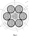
- Figure 1 shows a cross-section of an optical cable 10 for blown installation according to an embodiment of the present disclosure.
- the optical cable 10 comprises a central strength member 1 comprising at least one optical fibre 2 and a resin layer 3.
- Each optical fibre 2 comprises a glass core comprising an optical waveguide, for example a single mode optical waveguide, and a cladding surrounding the waveguide.
- a first polymeric coating surrounds the cladding and a second polymeric coating, optionally coloured, surrounds the first polymeric coating.
- each optical fibre 2 may further comprise a third polymeric coating, for example an ink layer, surrounding the second polymeric coating.
- Each optical fibre 2 can have an outer diameter of from 150 ⁇ m to 300 ⁇ m, for example from 180 ⁇ m to 250 ⁇ m.
- the optical fibres 2 may be arranged longitudinally (namely, parallel to the longitudinal axis of the optical cable 10).
- the central strength member 1 comprises a number of optical fibres 2 chosen so as to provide the central strength member 1 with a suitable stiffness for blown installation.
- the minimum number N min of optical fibres 2 in the central strength member 1 may be equal to 8
- the maximum number N max of optical fibres 2 may be equal to 12.
- the resin layer 3 has an outer diameter between, for example, 0.9 mm and 1.5 mm, depending on the number of optical fibres 2 and their outer diameter. For example, with 12 optical fibres 2 having a fibre diameter ranging from 180 ⁇ m to 250 ⁇ m, the resin layer 3 has a diameter ranging from 0.96 mm to 1.3 mm.
- the resin layer 3 comprises at least two layers, namely a first layer 3a and a second layer 3b.
- the first layer 3a and second layer 3b may be made of, respectively, a first and second resin material having secant modulus different one from the other, with the second resin material having a secant modulus higher than that of the first resin material.
- the lower secant modulus of the first resin material could prevent transferring external forces acting on the optical cable 10 (and then on the central strength member 1) to the optical fibres 2, while allowing easy removal from the optical fibres 2 without damaging them during installation in the field.
- the secant modulus of the first resin material is between 0.5 MPa and 25 MPa, for example between 0.6 MPa and 10 MPa, for example 1 MPa.
- the secant modulus of the second resin material may be between 500 MPa and 1000 MPa, for example between 600 MPa and 750 MPa, for example 668 MPa.
- the first layer 3a may have a diameter between about 50% and about 90% of the outer diameter of resin layer 3, for example about 85%.
- the outer diameter of the resin layer 3 is the outer diameter of the second layer 3b.
- the first resin of the first layer 3a comprises a matrix material with a high elongation at break, for example higher than about 130%.
- the second resin of the second layer 3b comprises a hard, fast curing matrix material.
- the second resin has a Shore D hardness of from 30 to 80 when cured.
- the optical cable 10 also comprise at least one tube 4 which, in the present case, are six tubes 4 arranged about the central strength member 1. Each tube 4 loosely houses a plurality of optical fibres 5.
- Each optical fibre 5 can have a fibre outer diameter of from 150 ⁇ m to 300 ⁇ m, for example from 180 ⁇ m to 250 ⁇ m.
- the optical fibres 5 may have a same diameter as the optical fibres 2, or a different diameter.
- each tube 4 comprises a maximum number N' max of optical fibres 5.
- the maximum number N' max of optical fibres 5 in each tube 4 may be equal to 24.
- the tubes 4 may be arranged longitudinally about the central strength member 1, namely parallel to the longitudinal axis of the optical cable 10. Alternatively, the tubes 4 may be oscillated about the central strength member 1 according to an open helix or "S-Z" pattern. Alternatively, the tubes 4 may be helically wound about the central strength member 1. Optionally, the tubes 4 may directly contact the outer surface of the resin layer 3 of the central strength member 1.
- the tubes 4 may be arranged to be in direct contact with the central strength member 1, i.e. in direct contact with the resin layer 3 thereof.
- the optical cable 10 may comprise up to six tubes 4 arranged about the central strength member 1.
- the optical cable 10 shown in Figure 1 comprises six tubes 4 arranged about the central strength member 1.
- each tube 4 may be substantially equal to the outer diameter of the central strength member 1.
- the outer diameter of each tube 4 is comprised between 0.9 mm and 1.5 mm, for example it is equal to about 1.1 mm or 1.3 mm.
- the tubes 4 may be made of a polyester material, e.g. a polybutylene terepthalate (PBT) resin, or of polypropylene, medium density polyethylene (MDPE) or high density polyethylene (HDPE).
- PBT polybutylene terepthalate
- MDPE medium density polyethylene
- HDPE high density polyethylene
- the thickness of the wall of the tubes 4 may be comprised between 0.03 mm and 0.07 mm.
- a water blocking compound 6 (in form, for example, of grease or gel) may be provided within each tube 4, to fill any space about the optical fibres 5 and among the optical fibres 5, so as to reach a filling of at least 95% of the space among the optical fibres 5 and the internal surface of the tube 4.
- the optical cable 10 also comprises an outer sheath 7 arranged about the tubes 4.
- the outer sheath 7 may be formed from an uncrosslinked high density polyethylene (HDPE).
- the material of the outer sheath 7 may be selected such that the coefficient of friction between the optical cable 10 and the duct in which the optical cable 10 is blown is lower than 0.12, measured using the inclined plane test defined by the European standard PD IEC/TR 62470:2011.
- the thickness of the outer sheath 7 may be comprised between 0.3 mm and 0.5 mm, for example it is equal to about 0.4 mm.
- a water blocking compound 8 (in form of grease or gel or longitudinally provided yarns) may be provided within the outer sheath 7, to fill any space about the tubes 4 which would otherwise be void.
- the optical cable 10 may also comprise at least one ripcord.
- the optical cable 10 shown in Figure 1 comprises two ripcords 9a, 9b.
- the ripcords 9a, 9b are arranged close to the inner wall of the outer sheath 7.
- the ripcords 9a, 9b are arranged at substantially diametrically opposed positions relative to the central strength member 1.
- the ripcords 9a, 9b advantageously ease removal of the outer sheath 7 for accessing the tubes 4 and central strength member 1.
- This construction of the optical cable 10 allows providing a high fibre density, while preserving the blowing properties (in particular, the stiffness) of the optical cable 10.
- such fibre count may be suitably distributed between the central strength member 1 and the tubes 4 arranged about the central strength member 1.
- the number of optical fibres 2 encased in the resin layer 3 of the central strength member 1 may be kept from a minimum value N min (e.g., 8) which guarantees that the central strength member 1 (and, hence, the whole optical cable 10) exhibits a stiffness adequate for blowing installation, to maximum value N max (e.g. 12).
- the rest of the requested fibre count may be instead loosely arranged in the tubes 4 about the central strength member 1.
- the obtained optical cable 10 exhibits a particularly high fibre density in a small cable size.
- high fibre counts namely, fibre counts higher than 72
- an overall diameter of the optical cable lower than 5 mm.
- Table I herein below shows two exemplary optical cables according to embodiments of the present disclosure.
- Both the exemplary optical cables comprise a central strength member in which 12 optical fibres are encased and, about the central strength member, 6 tubes loosely housing further optical fibres. All the optical fibres of both the exemplary cables have a diameter of 200 ⁇ m.
- the outer sheath has a thickness of 0.4 mm.
- Cable A comprises central strength member and tubes with a diameter of 1.1 mm. 12 optical fibres are arranged in each tube, such that the overall fibre count is 84.
- the cable diameter is 4.1 mm.
- Cable B instead comprises central strength member and tubes with a diameter of 1.3 mm.
- an increased number of optical fibres namely 24 optical fibres, may be loosely housed in each tube of Cable B.
- the overall fibre count is therefore 156, while the cable diameter is 4.8 mm. It may be appreciated that the fibre count of Cable B is almost doubled relative to Cable A, while the increase in the cable diameter is of less than 1 mm.
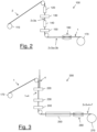
- the apparatus comprises a first stage and a second stage cascaded thereto.
- the first stage 100 is configured to manufacture a central strength member 1 comprising the resin layer 3 with the optical fibres 2 encased therein.
- a number of optical fibres 2 are unwound from a corresponding number of bobbins 110.
- the optical fibres 2 are passed through a first resin applicator 120 for applying the first layer 3a of resin.
- a first curing source 130 is provided.
- Such first curing source 130 could comprise a UV lamp or the like for curing the first layer of resin 3a.
- a second applicator 140 for applying the second layer 3b of resin may be provided and followed by a second curing source 150.
- Such second curing source 150 could comprise a UV lamp or the like for curing the resin of the second layer 3b.
- the first stage 100 of the apparatus could also comprise a capstan 160 before a take-up station 170.
- the second stage 200 of the apparatus is configured to provide the tubes 4 with the optical fibres 5 loosely housed therein and the outer sheath 7 onto the central strength member 1 provided by the first stage 100.
- the second stage 200 a number of tubes 4 in which optical fibres 5 are loosely housed are passed through a guide 220, by which they are arranged (longitudinally, helically or oscillated) about the central strength member 1.
- the stages assembling the tubes 4 with the optical fibres 5 loosely housed therein are not shown in Figure 3 and will not be described in detail.
- the central strength member 1 comprising the resin layer 3 with optical fibres 2 embedded therein and tubes 4 arranged about it may be passed through a tip 230, which injects the water blocking material onto the tubes 4, so that the water blocking material can penetrate amongst the tubes 4 and possibly embed them.
- the collection of resin layer 3, tubes 4 and, optionally, water blocking material is then passed through an extruder 240, which extrudes the outer sheath 7 upon the tubes 4 and, optionally, water blocking material.
- the optical cable 10 is then passed through a cooling trough 250.
- a capstan 260 and a take-up arrangement 270 can be provided.
Landscapes
- Physics & Mathematics (AREA)
- General Physics & Mathematics (AREA)
- Optics & Photonics (AREA)
- Engineering & Computer Science (AREA)
- Manufacturing & Machinery (AREA)
- Light Guides In General And Applications Therefor (AREA)
Abstract
It is disclosed an optical cable for blown installations comprising a central strength member comprising at least one optical fibre and a resin layer encasing the at least one optical fibre; at least one tube arranged about the central strength member and loosely housing at least one further optical fibre; and an outer jacket surrounding the least one tube. Also disclosed are an apparatus and a method for manufacturing such optical cable.
Description
- The present disclosure relates to optical cables for blown installation. In particular, the present disclosure relates to an optical cable for blown or overblown installation having a high fibre density. The present disclosure also relates to a method and apparatus for manufacturing such an optical cable.
- Optical cables are commonly deployed by installing them in ducts by blowing or pulling, burying them in the ground, or suspending them between above-ground poles.
- One method of installing an optical cable in a duct comprises blowing the cable into the duct (or overblowing, in the case the duct already contains an active optical cable) using gaseous flow which is fed into an inlet end of the duct together with the cable. The length of optical cable which can be blown into the duct can be increased by applying an additional pushing force to the cable at the inlet end of the duct.
- In the following of the description and claims as "blown" and the derivatives will be referred to both the blown and the overblown, unless specifically indicated.
- Unlike cables which are to be pulled through ducting, optical cables for blown installation do not have to withstand high tensile loads, but they require a degree of stiffness for the application of the gaseous flow. Besides, in order to maximize the blowing performance of an optical cable (in term of distance of deposition achieved), it is advisable that the optical cable has a neutral bending axis. Multi loose tube (MLT) optical cables exhibit this property and are accordingly often used for blown installation.
- An MLT optical cable in general comprises a core made of a plurality of tubes arranged about a central strength member. The central strength member provides stiffness to the optical cable, as required for blown installation. Each tube loosely houses a number of optical fibers. The cable also comprises an outer sheath surrounding the core.
-
WO 2002/012943 discloses an optical cable for blown installation whose central strength member is tubular and has a peripheral wall enclosing a passage extending along the length of the central strength member. A tube member loosely housing optical fibres may be accommodated within the passage of the central strength member. -
US 7,027,697 discloses an optical cable for blown installation which also includes, in addition to the loose tubes stranded about the central strength member and the outer jacket, also a conduit configured to receive blown optical fibres and positioned external to the central strength member. The central strength member may include a bore configured to receive central blown optical fibres. - The need for optical cables for blown installation with fibre counts of 48 or more and outer diameters of less than 5.0 mm has emerged from the network operators.
- While known MLT optical cables allow reaching fibre counts of 48 or more, an overall cable diameter of less than 5.0 mm in general requires that the central strength member has a very small diameter, typically 1.0 mm. Such a small diameter of the central strength member reduces the cable stiffness, and therefore worsens the blowing performance of the MLT cable (in term of distance of deposition achieved). Moreover, a small diameter of the central strength member results in a reduced stiffness of the central strength member itself, which could then break during the blown installation procedure.
- These considerations could apply to the optical cables described by
WO 2002/012943 andUS 7,027,697 , whose central strength member is moreover hollow to loosely house optical fibres, and accordingly may entail an even more severe reduction of the cable stiffness and of the stiffness of the central strength member itself. - The Applicant has then faced the problem of providing an optical cable for blown installation which overcomes the aforesaid drawbacks.
- In particular, the Applicant has tackled the problem of providing an optical cable for blown installation which exhibits both an adequate stiffness and a high fibre density, where "fibre density" indicates the ratio between the fibre count of the optical cable (namely, the number of optical fibres comprised in the optical cable) and the outer diameter of the optical cable.
- According to embodiments of the present disclosure, this problem is solved by an optical cable for blown installation comprising a central strength member comprising at least one optical fibre and a resin layer encasing the at least one optical fibre; at least one tube arranged about the central strength member and at least one further optical fibre loosely housed in the least one tube; and an outer sheath surrounding the least one tube.
- This construction of the optical cable allows to provide a high fibre density, while preserving the blowing properties (in particular, the stiffness) of the optical cable. Given a certain fibre count requested by the network operator, indeed, such fibre count may be suitably distributed between the central strength member and the tube(s) arranged about the central strength member. For example, the number of optical fibres encased in the resin layer of the central strength member may be kept below or equal to a maximum value (e.g. 12) which guarantees that the central strength member (and, hence, the whole optical cable) exhibits a stiffness adequate for blowing installation. The rest of the requested fibre count is instead loosely arranged in the tube(s) about the central member.
- The obtained optical cable exhibits a particularly high fibre density. As it will be discussed in detail herein below, the Applicant has indeed estimated that high fibre counts (namely, fibre counts higher than 72) may be obtained with an overall diameter of the optical cable lower than 5 mm.
- Therefore, according to a first aspect, the present disclosure provides an optical cable for blown installation comprising:
- a central strength member comprising at least one optical fibre and a resin layer encasing the at least one optical fibre;
- at least one tube arranged about the central strength member and loosely housing at least one further optical fibre; and
- an outer sheath surrounding the least one tube.
- In an embodiment, the at least one tube is in direct contact with an outer surface of the resin layer of the central strength member.
- The at least one tube may be wounded or oscillated about the central strength member. Alternatively, the at least one tube may be laid parallel to a longitudinal axis of the optical cable.
- In an embodiment, the optical cable further comprises a water blocking material within the outer sheath. The water blocking material may at least partially embed the at least one tube.
- In an embodiment, the central strength member may comprise at most 12 optical fibres.
- The optical cable may comprise at most 6 tubes arranged about the central member.
- Each tube may loosely house at most 24 further optical fibres.
- In an embodiment, each of the central strength member and the at least one tube has diameters comprised between 0.9 mm and 1.5 mm.
- In an embodiment, the central strength member and the at least one tube have substantially the same diameter.
- In an embodiment, the resin layer of the central strength member comprises at least one acrylate material.
- In an embodiment, the central strength member comprises a resin layer composed of first layer of first resin material and a second layer of second resin material radially outer to the first layer, wherein the second resin material has a secant modulus higher than a secant modulus of the first resin material.
- In an embodiment, the secant modulus of the first resin material is between 0.5 MPa and 25 MPa.
- In an embodiment, the secant modulus of the second resin material is between 500 MPa and 1000 MPa.
- According to a second aspect, the present disclosure provides a method for manufacturing an optical cable for blown installation, the method comprising:
- encasing at least one optical fibre in a resin layer;
- curing the resin layer to obtain a central strength member;
- arranging about the resin layer at least one tube loosely housing at least one further optical fibre; and
- extruding an outer sheath in a radially outer position with respect to the at least one tube.
- According to a third aspect, the present disclosure provides an apparatus for manufacturing an optical cable for blown installation, the apparatus comprising:
- at least one resin applicator for applying at least one resin material on at least one optical fibre and at least one curing device for curing the at least one resin material;
- a guide for providing at least one tube loosely housing at least one further optical fibre about the resin material; and
- an extruder for forming an outer sheath around the at least one tube.
- In the present description and claims:
- the term "radial" and the related terms are used to indicate a direction perpendicular to a reference longitudinal axis of the optical cable;
- the expressions "radially inner" and "radially outer" are used to indicate a position along a radial direction with respect to the above-mentioned longitudinal axis;
- a size along the radial direction is termed "thickness"; and
- the verb "to encase" means to completely surround and directly contact from the outside.
- The Shore hardness has been evaluated according to ISO 868 (2003-03-01). The tensile strength, the elongation at break and the secant modulus have been evaluated according to ISO 527-1 (2012).
- For the purpose of the present description and of the appended claims, except where otherwise indicated, all numbers expressing amounts, quantities, percentages, and so forth, are to be understood as being modified in all instances by the term "about". Also, all ranges include any combination of the maximum and minimum points disclosed and include any intermediate ranges therein, which may or may not be specifically enumerated herein.
- For the purpose of the present description and of the appended claims, the words "a" or "an" should be read to include one or at least one and the singular also includes the plural unless it is obvious that it is meant otherwise. This is done merely for convenience and to give a general sense of the disclosure.
- The present disclosure, in at least one of the aforementioned aspects, can be implemented according to one or more of the present embodiments, optionally combined together.
- The present disclosure will provide further particulars in the following detailed description, given by way of example and not of limitation, with reference to the following drawings, wherein:
-
Figure 1 shows a cross-section of an optical cable for blown installation according to an embodiment of the present disclosure; and -
Figures 2 and 3 schematically show an apparatus for carrying out the process for manufacturing the optical cable according to an embodiment of the present disclosure. -
Figure 1 shows a cross-section of anoptical cable 10 for blown installation according to an embodiment of the present disclosure. - The
optical cable 10 comprises acentral strength member 1 comprising at least oneoptical fibre 2 and aresin layer 3. - Each
optical fibre 2 comprises a glass core comprising an optical waveguide, for example a single mode optical waveguide, and a cladding surrounding the waveguide. A first polymeric coating surrounds the cladding and a second polymeric coating, optionally coloured, surrounds the first polymeric coating. According to embodiments, eachoptical fibre 2 may further comprise a third polymeric coating, for example an ink layer, surrounding the second polymeric coating. - Each
optical fibre 2 can have an outer diameter of from 150 µm to 300 µm, for example from 180 µm to 250 µm. - The
optical fibres 2 may be arranged longitudinally (namely, parallel to the longitudinal axis of the optical cable 10). In an embodiment, thecentral strength member 1 comprises a number ofoptical fibres 2 chosen so as to provide thecentral strength member 1 with a suitable stiffness for blown installation. For example, the minimum number Nmin ofoptical fibres 2 in thecentral strength member 1 may be equal to 8, and the maximum number Nmax ofoptical fibres 2 may be equal to 12. - The
resin layer 3 is a resin solid matrix which encases theoptical fibres 2, where "encases" means that the resin completely surrounds the bundle ofoptical fibres 2 and directly contacts them from the outside. The resin however does not necessarily penetrate amongst the bundledoptical fibres 2, namely it does not necessarily fill the voids and gaps among theoptical fibres 2. - The
resin layer 3 has an outer diameter between, for example, 0.9 mm and 1.5 mm, depending on the number ofoptical fibres 2 and their outer diameter. For example, with 12optical fibres 2 having a fibre diameter ranging from 180 µm to 250 µm, theresin layer 3 has a diameter ranging from 0.96 mm to 1.3 mm. - The
resin layer 3 may be made of a soft resin material which cushions theoptical fibres 2. For example, theresin layer 3 may be made of a thermoplastic or thermosetting plastic material derived from acrylic acid, methacrylic acid or other related compounds. For example, theresin layer 3 comprises an acrylate resin. The acrylate resin of theresin layer 3 may be an ultraviolet (UV) curable acrylate resin. - According to the embodiment shown in
Figure 1 , theresin layer 3 comprises at least two layers, namely afirst layer 3a and asecond layer 3b. Thefirst layer 3a andsecond layer 3b may be made of, respectively, a first and second resin material having secant modulus different one from the other, with the second resin material having a secant modulus higher than that of the first resin material. Without wishing to be bound to any theory, the lower secant modulus of the first resin material could prevent transferring external forces acting on the optical cable 10 (and then on the central strength member 1) to theoptical fibres 2, while allowing easy removal from theoptical fibres 2 without damaging them during installation in the field. - As "secant modulus" it is meant the slope of a line between the 0 point and a point at 2.5% strain in the stress-strain curve of the material under measurement, tested at 25°C and 50% relative humidity.
- In an embodiment, the secant modulus of the first resin material is between 0.5 MPa and 25 MPa, for example between 0.6 MPa and 10 MPa, for example 1 MPa. Further, the secant modulus of the second resin material may be between 500 MPa and 1000 MPa, for example between 600 MPa and 750 MPa, for example 668 MPa.
- The
first layer 3a may have a diameter between about 50% and about 90% of the outer diameter ofresin layer 3, for example about 85%. The outer diameter of theresin layer 3 is the outer diameter of thesecond layer 3b. - The
first layer 3a may substantially surround all theoptical fibres 2, so that there is at least some material with a thickness of about 1 µm to about 10 µm between two adjacentoptical fibres 2 over the majority of the length. - In an embodiment, the first resin of the
first layer 3a comprises a matrix material with a high elongation at break, for example higher than about 130%. - In an embodiment, the second resin of the
second layer 3b comprises a hard, fast curing matrix material. For example, the second resin has a Shore D hardness of from 30 to 80 when cured. - The
optical cable 10 also comprise at least onetube 4 which, in the present case, are sixtubes 4 arranged about thecentral strength member 1. Eachtube 4 loosely houses a plurality ofoptical fibres 5. - Each
optical fibre 5 comprises a glass core comprising an optical waveguide, for example a single mode optical waveguide, and a cladding surrounding the waveguide. A first polymeric coating surrounds the cladding and a second polymeric coating, optionally coloured, surrounds the first polymeric coating. According to embodiments, eachoptical fibre 5 may further comprise a third polymeric coating, for example an ink layer, surrounding the second polymeric coating. - Each
optical fibre 5 can have a fibre outer diameter of from 150 µm to 300 µm, for example from 180 µm to 250 µm. Theoptical fibres 5 may have a same diameter as theoptical fibres 2, or a different diameter. - Within each
tube 4, theoptical fibres 5 may be arranged in a bundle. In an embodiment, eachtube 4 comprises a maximum number N'max ofoptical fibres 5. For example, the maximum number N'max ofoptical fibres 5 in eachtube 4 may be equal to 24. - The
tubes 4 may be arranged longitudinally about thecentral strength member 1, namely parallel to the longitudinal axis of theoptical cable 10. Alternatively, thetubes 4 may be oscillated about thecentral strength member 1 according to an open helix or "S-Z" pattern. Alternatively, thetubes 4 may be helically wound about thecentral strength member 1. Optionally, thetubes 4 may directly contact the outer surface of theresin layer 3 of thecentral strength member 1. - The
tubes 4 may be arranged to be in direct contact with thecentral strength member 1, i.e. in direct contact with theresin layer 3 thereof. - The
optical cable 10 may comprise up to sixtubes 4 arranged about thecentral strength member 1. By way of non-limiting example, theoptical cable 10 shown inFigure 1 comprises sixtubes 4 arranged about thecentral strength member 1. - The outer diameter of each
tube 4 may be substantially equal to the outer diameter of thecentral strength member 1. In an embodiment, the outer diameter of eachtube 4 is comprised between 0.9 mm and 1.5 mm, for example it is equal to about 1.1 mm or 1.3 mm. - The
tubes 4 may be made of a polyester material, e.g. a polybutylene terepthalate (PBT) resin, or of polypropylene, medium density polyethylene (MDPE) or high density polyethylene (HDPE). The thickness of the wall of thetubes 4 may be comprised between 0.03 mm and 0.07 mm. - A water blocking compound 6 (in form, for example, of grease or gel) may be provided within each
tube 4, to fill any space about theoptical fibres 5 and among theoptical fibres 5, so as to reach a filling of at least 95% of the space among theoptical fibres 5 and the internal surface of thetube 4. - The
optical cable 10 also comprises anouter sheath 7 arranged about thetubes 4. Theouter sheath 7 may be formed from an uncrosslinked high density polyethylene (HDPE). In any case, the material of theouter sheath 7 may be selected such that the coefficient of friction between theoptical cable 10 and the duct in which theoptical cable 10 is blown is lower than 0.12, measured using the inclined plane test defined by the European standard PD IEC/TR 62470:2011. - The thickness of the
outer sheath 7 may be comprised between 0.3 mm and 0.5 mm, for example it is equal to about 0.4 mm. - A water blocking compound 8 (in form of grease or gel or longitudinally provided yarns) may be provided within the
outer sheath 7, to fill any space about thetubes 4 which would otherwise be void. - The
optical cable 10 may also comprise at least one ripcord. By way of non-limiting example, theoptical cable 10 shown inFigure 1 comprises tworipcords ripcords outer sheath 7. In the present embodiment, theripcords central strength member 1. Theripcords outer sheath 7 for accessing thetubes 4 andcentral strength member 1. - This construction of the
optical cable 10 allows providing a high fibre density, while preserving the blowing properties (in particular, the stiffness) of theoptical cable 10. Given a certain fibre count requested by the network operator, indeed, such fibre count may be suitably distributed between thecentral strength member 1 and thetubes 4 arranged about thecentral strength member 1. For example, the number ofoptical fibres 2 encased in theresin layer 3 of thecentral strength member 1 may be kept from a minimum value Nmin (e.g., 8) which guarantees that the central strength member 1 (and, hence, the whole optical cable 10) exhibits a stiffness adequate for blowing installation, to maximum value Nmax (e.g. 12). The rest of the requested fibre count may be instead loosely arranged in thetubes 4 about thecentral strength member 1. - The obtained
optical cable 10 exhibits a particularly high fibre density in a small cable size. The Applicant has indeed estimated that high fibre counts (namely, fibre counts higher than 72) may be obtained with an overall diameter of the optical cable lower than 5 mm. - For example, Table I herein below shows two exemplary optical cables according to embodiments of the present disclosure. Both the exemplary optical cables comprise a central strength member in which 12 optical fibres are encased and, about the central strength member, 6 tubes loosely housing further optical fibres. All the optical fibres of both the exemplary cables have a diameter of 200 µm. For both the exemplary cables, the outer sheath has a thickness of 0.4 mm.
Table I Cable A Cable B diameter of tubes 1.1 mm 1.3 mm diameter of central strength member 1.1 mm 1.3 mm No. optical fibres per tube 12 24 fiber count of the cable 12+(12x6) = 84 12+(24x6) = 156 cable diameter 4.1 mm 4.8 mm - Cable A comprises central strength member and tubes with a diameter of 1.1 mm. 12 optical fibres are arranged in each tube, such that the overall fibre count is 84. The cable diameter is 4.1 mm.
- Cable B instead comprises central strength member and tubes with a diameter of 1.3 mm. As the diameter of the tubes of Cable B is larger than that of the tube of Cable A, an increased number of optical fibres, namely 24 optical fibres, may be loosely housed in each tube of Cable B. The overall fibre count is therefore 156, while the cable diameter is 4.8 mm. It may be appreciated that the fibre count of Cable B is almost doubled relative to Cable A, while the increase in the cable diameter is of less than 1 mm.
- With reference to
Figures 2 and 3 , an apparatus for manufacturing theoptical cable 10 according to an embodiment of the present disclosure will be described in detail. - The apparatus comprises a first stage and a second stage cascaded thereto.
- The
first stage 100, shown inFigure 2 , is configured to manufacture acentral strength member 1 comprising theresin layer 3 with theoptical fibres 2 encased therein. - In the
first stage 100, a number ofoptical fibres 2 are unwound from a corresponding number ofbobbins 110. According to an embodiment of the disclosure, theoptical fibres 2 are passed through afirst resin applicator 120 for applying thefirst layer 3a of resin. After thefirst resin applicator 120, afirst curing source 130 is provided. Suchfirst curing source 130 could comprise a UV lamp or the like for curing the first layer ofresin 3a. - As shown in
Figure 2 , asecond applicator 140 for applying thesecond layer 3b of resin may be provided and followed by asecond curing source 150. Suchsecond curing source 150 could comprise a UV lamp or the like for curing the resin of thesecond layer 3b. - The
first stage 100 of the apparatus could also comprise acapstan 160 before a take-upstation 170. - The
second stage 200 of the apparatus, shown inFigure 3 , is configured to provide thetubes 4 with theoptical fibres 5 loosely housed therein and theouter sheath 7 onto thecentral strength member 1 provided by thefirst stage 100. - In the
second stage 200, a number oftubes 4 in whichoptical fibres 5 are loosely housed are passed through aguide 220, by which they are arranged (longitudinally, helically or oscillated) about thecentral strength member 1. The stages assembling thetubes 4 with theoptical fibres 5 loosely housed therein are not shown inFigure 3 and will not be described in detail. Then, thecentral strength member 1 comprising theresin layer 3 withoptical fibres 2 embedded therein andtubes 4 arranged about it may be passed through atip 230, which injects the water blocking material onto thetubes 4, so that the water blocking material can penetrate amongst thetubes 4 and possibly embed them. The collection ofresin layer 3,tubes 4 and, optionally, water blocking material is then passed through anextruder 240, which extrudes theouter sheath 7 upon thetubes 4 and, optionally, water blocking material. Theoptical cable 10 is then passed through acooling trough 250. - Finally, a
capstan 260 and a take-uparrangement 270 can be provided.
Claims (16)
- An optical cable (10) for blown installation comprising:- a central strength member (1) comprising at least one optical fibre (2) and a resin layer (3) encasing the at least one optical fibre (2);- at least one tube (4) arranged about the central strength member (1) and loosely housing at least one further optical fibre (5); and- an outer sheath (7) surrounding the least one tube (4).
- The optical cable (10) according to claim 1, wherein the at least one tube (4) is in direct contact with an outer surface of the resin layer (3) of the central strength member (1).
- The optical cable (10) according to claim 1, wherein the at least one tube (4) is wounded or oscillated about the central strength member (1).
- The optical cable (10) according to claim 1, wherein the at least one tube (4) is laid parallel to a longitudinal axis of the optical cable (10).
- The optical cable (10) according to claim 1, further comprising a water blocking material (8) within the outer sheath (7), the water blocking material (8) at least partially embedding the at least one tube (4).
- The optical cable (10) according to claim 1, wherein the central strength member (1) comprises from 8 to 12 optical fibres (2).
- The optical cable (10) according to claim 1, wherein the optical cable (10) comprises at most 6 tubes (4) arranged about the central member (1).
- The optical cable (10) according to claim 7, wherein each tube (4) loosely houses at most 24 further optical fibres (5).
- The optical cable (10) according to claim 1, wherein the central strength member (1) and the at least one tube (4) have diameters between 0.9 mm and 1.5 mm.
- The optical cable (10) according to claim 1, wherein the central strength member (1) and the at least one tube (4) have substantially a same diameter.
- The optical cable (10) according to claim 1, wherein the resin layer (3) comprises at least one acrylate material.
- The optical cable (10) according to claim 1, wherein the resin layer (3) comprises a first layer (3a) of a first resin material and a second layer (3b) of a second resin material radially outer to the first layer (3a), wherein the second resin material has a secant modulus higher than a secant modulus of the first resin material.
- The optical cable (10) according to claim 12, wherein the secant modulus of the first resin material is between 0.5 MPa and 25 MPa.
- The optical cable (10) according to claim 12, wherein the secant modulus of the second resin material is between 500 MPa and 1000 MPa.
- A method for manufacturing an optical cable (10) for blown installation, said method comprising:- encasing at least one optical fibre (2) in a resin layer (3) to obtain a central strength member (1);- arranging about the resin layer (3) at least one tube (4) loosely housing at least one further optical fibre (5); and- extruding an outer sheath (7) in a radially outer position with respect to the at least one tube (4).
- An apparatus (100, 200) for manufacturing an optical cable (10) for blown installation, the apparatus (100, 200) comprising:- at least one resin applicator (120, 140) for applying at least one resin material (3a, 3b) on at least one optical fibre (2) and at least one curing device (130, 150) for curing the at least one resin material (3a, 3b);- a guide (220) for providing at least one tube (4) loosely housing at least one further optical fibre (5) about the resin material (3a, 3b); and- an extruder (240) for forming an outer sheath (7) around the at least one tube (4).
Applications Claiming Priority (1)
| Application Number | Priority Date | Filing Date | Title |
|---|---|---|---|
| IT102022000026130A IT202200026130A1 (en) | 2022-12-20 | 2022-12-20 | Optical cable for installation by blowing |
Publications (1)
| Publication Number | Publication Date |
|---|---|
| EP4390489A1 true EP4390489A1 (en) | 2024-06-26 |
Family
ID=85284970
Family Applications (1)
| Application Number | Title | Priority Date | Filing Date |
|---|---|---|---|
| EP23216841.9A Pending EP4390489A1 (en) | 2022-12-20 | 2023-12-14 | Optical cable for blown installation |
Country Status (4)
| Country | Link |
|---|---|
| US (1) | US20240201461A1 (en) |
| EP (1) | EP4390489A1 (en) |
| AU (1) | AU2023285705A1 (en) |
| IT (1) | IT202200026130A1 (en) |
Citations (5)
| Publication number | Priority date | Publication date | Assignee | Title |
|---|---|---|---|---|
| WO2002012943A1 (en) | 2000-08-07 | 2002-02-14 | Pirelli General Plc | Optical fibre cable |
| EP1600801A2 (en) * | 2002-08-10 | 2005-11-30 | Emtelle UK Limited | Protective covering for optical fiber cable |
| EP1600802A2 (en) * | 2002-08-10 | 2005-11-30 | Emtelle UK Limited | Signal transmitting cable |
| US7027697B2 (en) | 2001-12-28 | 2006-04-11 | Pirelli Communications Cables And Systems Usa, Llc | Cable having conduits for receiving optical fibers |
| US20160274324A1 (en) * | 2013-11-29 | 2016-09-22 | Prysmian S.P.A. | High installation performance blown optical fibre unit, manufacturing method and apparatus |
Family Cites Families (13)
| Publication number | Priority date | Publication date | Assignee | Title |
|---|---|---|---|---|
| GB1587729A (en) * | 1976-07-08 | 1981-04-08 | Bicc Ltd | Optical guides |
| US5905834A (en) * | 1997-07-21 | 1999-05-18 | Pirelli Cable Corporation | Combination loose tube optical fiber cable with reverse oscillating lay |
| FR2814245B1 (en) * | 2000-09-21 | 2002-12-06 | Cit Alcatel | IMPROVED OPTICAL FIBER CABLE AND MANUFACTURING METHOD THEREOF |
| US6853781B2 (en) * | 2001-08-13 | 2005-02-08 | Sumitomo Electric Lightwave Corp. | Air blown fiber (ABF) cable with low composite coefficient of thermal expansion |
| FR2849929B1 (en) * | 2003-01-09 | 2005-04-15 | Sagem | OPTICAL FIBER CABLE WITH MAINTAINING SHEATH |
| WO2007021673A2 (en) * | 2005-08-12 | 2007-02-22 | Afl Telecommunications Llc | Tapered cable for use in fiber to the premises applications |
| US8467645B2 (en) * | 2009-08-20 | 2013-06-18 | Nexans | Fiber optic arrangement using flat wide water swellable binder for subunit access |
| US8494327B2 (en) * | 2010-10-19 | 2013-07-23 | Nexans | Expanded four fiber unit cable for increased fiber count cables having increased flexibility and fiber strength utilization |
| US8855455B2 (en) * | 2011-11-23 | 2014-10-07 | Nexans | Fiber optic cable |
| US8909012B2 (en) * | 2012-04-27 | 2014-12-09 | Corning Cable Systems Llc | Hybrid cable including fiber-optic and electrical-conductor stranded elements |
| EP3764144B1 (en) * | 2019-07-09 | 2023-02-22 | Corning Research & Development Corporation | Flame retardant fiber optic cable with halogen free sheath for blowing applications |
| WO2021178134A1 (en) * | 2020-03-06 | 2021-09-10 | Corning Research & Development Corporation | Preconnectorized distribution cable assemblies and methods of making by jacket segmentation |
| WO2022260903A1 (en) * | 2021-06-08 | 2022-12-15 | Corning Research & Development Corporation | Thin film bundled cable |
-
2022
- 2022-12-20 IT IT102022000026130A patent/IT202200026130A1/en unknown
-
2023
- 2023-12-14 EP EP23216841.9A patent/EP4390489A1/en active Pending
- 2023-12-18 AU AU2023285705A patent/AU2023285705A1/en active Pending
- 2023-12-19 US US18/389,622 patent/US20240201461A1/en active Pending
Patent Citations (5)
| Publication number | Priority date | Publication date | Assignee | Title |
|---|---|---|---|---|
| WO2002012943A1 (en) | 2000-08-07 | 2002-02-14 | Pirelli General Plc | Optical fibre cable |
| US7027697B2 (en) | 2001-12-28 | 2006-04-11 | Pirelli Communications Cables And Systems Usa, Llc | Cable having conduits for receiving optical fibers |
| EP1600801A2 (en) * | 2002-08-10 | 2005-11-30 | Emtelle UK Limited | Protective covering for optical fiber cable |
| EP1600802A2 (en) * | 2002-08-10 | 2005-11-30 | Emtelle UK Limited | Signal transmitting cable |
| US20160274324A1 (en) * | 2013-11-29 | 2016-09-22 | Prysmian S.P.A. | High installation performance blown optical fibre unit, manufacturing method and apparatus |
Also Published As
| Publication number | Publication date |
|---|---|
| US20240201461A1 (en) | 2024-06-20 |
| AU2023285705A1 (en) | 2024-07-04 |
| IT202200026130A1 (en) | 2024-06-20 |
Similar Documents
| Publication | Publication Date | Title |
|---|---|---|
| US11042000B2 (en) | Optical cable for terrestrial networks | |
| CN103777291B (en) | Optical fiber cable | |
| US6785450B2 (en) | Self-supporting fiber optic cable | |
| US8265438B2 (en) | Optical cable with stranded micromodules | |
| US7570852B2 (en) | Optical fiber cable suited for blown installation or pushing installation in microducts of small diameter | |
| CN101153942B (en) | A loose tube optical waveguide fiber cable | |
| CN101065697A (en) | Optical fiber cable with fiber receiving jacket ducts | |
| US11714248B2 (en) | High density bundled optical fiber cable with preconnectorized drop points | |
| US6778744B2 (en) | Dielectric optical fiber cable having reduced preferential bending | |
| US6876800B2 (en) | Optical fiber cable | |
| CA2541953C (en) | Fiber optic assemblies, cables, and manufacturing methods therefor | |
| AU2013406410B2 (en) | High installation performance blown optical fibre unit, manufacturing method and apparatus | |
| US20240201461A1 (en) | Optical cable for blown installation | |
| US20230079855A1 (en) | Optical fibre unit for air-blown installation | |
| KR20260025525A (en) | Compact, Small Core Loose Tube Optical Cable Accepting Toneable Conductor And Dark Fiber And Manufacturing Method Thereof | |
| CA3061669A1 (en) | Methods for forming fiber optic cables and fiber optic cables having helical buffer tubes |
Legal Events
| Date | Code | Title | Description |
|---|---|---|---|
| PUAI | Public reference made under article 153(3) epc to a published international application that has entered the european phase |
Free format text: ORIGINAL CODE: 0009012 |
|
| STAA | Information on the status of an ep patent application or granted ep patent |
Free format text: STATUS: THE APPLICATION HAS BEEN PUBLISHED |
|
| AK | Designated contracting states |
Kind code of ref document: A1 Designated state(s): AL AT BE BG CH CY CZ DE DK EE ES FI FR GB GR HR HU IE IS IT LI LT LU LV MC ME MK MT NL NO PL PT RO RS SE SI SK SM TR |
|
| STAA | Information on the status of an ep patent application or granted ep patent |
Free format text: STATUS: REQUEST FOR EXAMINATION WAS MADE |
|
| 17P | Request for examination filed |
Effective date: 20241216 |