EP4390455A1 - Electronic device, method for controlling electronic device, and program - Google Patents
Electronic device, method for controlling electronic device, and program Download PDFInfo
- Publication number
- EP4390455A1 EP4390455A1 EP22858319.1A EP22858319A EP4390455A1 EP 4390455 A1 EP4390455 A1 EP 4390455A1 EP 22858319 A EP22858319 A EP 22858319A EP 4390455 A1 EP4390455 A1 EP 4390455A1
- Authority
- EP
- European Patent Office
- Prior art keywords
- electronic device
- transmission
- subject
- signal
- wave
- Prior art date
- Legal status (The legal status is an assumption and is not a legal conclusion. Google has not performed a legal analysis and makes no representation as to the accuracy of the status listed.)
- Pending
Links
Images






Classifications
-
- G—PHYSICS
- G01—MEASURING; TESTING
- G01S—RADIO DIRECTION-FINDING; RADIO NAVIGATION; DETERMINING DISTANCE OR VELOCITY BY USE OF RADIO WAVES; LOCATING OR PRESENCE-DETECTING BY USE OF THE REFLECTION OR RERADIATION OF RADIO WAVES; ANALOGOUS ARRANGEMENTS USING OTHER WAVES
- G01S13/00—Systems using the reflection or reradiation of radio waves, e.g. radar systems; Analogous systems using reflection or reradiation of waves whose nature or wavelength is irrelevant or unspecified
- G01S13/02—Systems using reflection of radio waves, e.g. primary radar systems; Analogous systems
- G01S13/50—Systems of measurement based on relative movement of target
- G01S13/58—Velocity or trajectory determination systems; Sense-of-movement determination systems
- G01S13/583—Velocity or trajectory determination systems; Sense-of-movement determination systems using transmission of continuous unmodulated waves, amplitude-, frequency-, or phase-modulated waves and based upon the Doppler effect resulting from movement of targets
- G01S13/584—Velocity or trajectory determination systems; Sense-of-movement determination systems using transmission of continuous unmodulated waves, amplitude-, frequency-, or phase-modulated waves and based upon the Doppler effect resulting from movement of targets adapted for simultaneous range and velocity measurements
-
- A—HUMAN NECESSITIES
- A61—MEDICAL OR VETERINARY SCIENCE; HYGIENE
- A61B—DIAGNOSIS; SURGERY; IDENTIFICATION
- A61B5/00—Measuring for diagnostic purposes; Identification of persons
- A61B5/103—Measuring devices for testing the shape, pattern, colour, size or movement of the body or parts thereof, for diagnostic purposes
- A61B5/11—Measuring movement of the entire body or parts thereof, e.g. head or hand tremor or mobility of a limb
-
- A—HUMAN NECESSITIES
- A61—MEDICAL OR VETERINARY SCIENCE; HYGIENE
- A61B—DIAGNOSIS; SURGERY; IDENTIFICATION
- A61B5/00—Measuring for diagnostic purposes; Identification of persons
- A61B5/02—Detecting, measuring or recording for evaluating the cardiovascular system, e.g. pulse, heart rate, blood pressure or blood flow
-
- A—HUMAN NECESSITIES
- A61—MEDICAL OR VETERINARY SCIENCE; HYGIENE
- A61B—DIAGNOSIS; SURGERY; IDENTIFICATION
- A61B5/00—Measuring for diagnostic purposes; Identification of persons
- A61B5/02—Detecting, measuring or recording for evaluating the cardiovascular system, e.g. pulse, heart rate, blood pressure or blood flow
- A61B5/024—Measuring pulse rate or heart rate
- A61B5/0245—Measuring pulse rate or heart rate by using sensing means generating electric signals, i.e. ECG signals
-
- A—HUMAN NECESSITIES
- A61—MEDICAL OR VETERINARY SCIENCE; HYGIENE
- A61B—DIAGNOSIS; SURGERY; IDENTIFICATION
- A61B5/00—Measuring for diagnostic purposes; Identification of persons
- A61B5/05—Detecting, measuring or recording for diagnosis by means of electric currents or magnetic fields; Measuring using microwaves or radio waves
- A61B5/0507—Detecting, measuring or recording for diagnosis by means of electric currents or magnetic fields; Measuring using microwaves or radio waves using microwaves or terahertz waves
-
- A—HUMAN NECESSITIES
- A61—MEDICAL OR VETERINARY SCIENCE; HYGIENE
- A61B—DIAGNOSIS; SURGERY; IDENTIFICATION
- A61B5/00—Measuring for diagnostic purposes; Identification of persons
- A61B5/103—Measuring devices for testing the shape, pattern, colour, size or movement of the body or parts thereof, for diagnostic purposes
- A61B5/11—Measuring movement of the entire body or parts thereof, e.g. head or hand tremor or mobility of a limb
- A61B5/113—Measuring movement of the entire body or parts thereof, e.g. head or hand tremor or mobility of a limb occurring during breathing
-
- G—PHYSICS
- G01—MEASURING; TESTING
- G01S—RADIO DIRECTION-FINDING; RADIO NAVIGATION; DETERMINING DISTANCE OR VELOCITY BY USE OF RADIO WAVES; LOCATING OR PRESENCE-DETECTING BY USE OF THE REFLECTION OR RERADIATION OF RADIO WAVES; ANALOGOUS ARRANGEMENTS USING OTHER WAVES
- G01S13/00—Systems using the reflection or reradiation of radio waves, e.g. radar systems; Analogous systems using reflection or reradiation of waves whose nature or wavelength is irrelevant or unspecified
- G01S13/02—Systems using reflection of radio waves, e.g. primary radar systems; Analogous systems
- G01S13/06—Systems determining position data of a target
- G01S13/08—Systems for measuring distance only
- G01S13/32—Systems for measuring distance only using transmission of continuous waves, whether amplitude-, frequency-, or phase-modulated, or unmodulated
- G01S13/34—Systems for measuring distance only using transmission of continuous waves, whether amplitude-, frequency-, or phase-modulated, or unmodulated using transmission of continuous, frequency-modulated waves while heterodyning the received signal, or a signal derived therefrom, with a locally-generated signal related to the contemporaneously transmitted signal
- G01S13/343—Systems for measuring distance only using transmission of continuous waves, whether amplitude-, frequency-, or phase-modulated, or unmodulated using transmission of continuous, frequency-modulated waves while heterodyning the received signal, or a signal derived therefrom, with a locally-generated signal related to the contemporaneously transmitted signal using sawtooth modulation
-
- G—PHYSICS
- G01—MEASURING; TESTING
- G01S—RADIO DIRECTION-FINDING; RADIO NAVIGATION; DETERMINING DISTANCE OR VELOCITY BY USE OF RADIO WAVES; LOCATING OR PRESENCE-DETECTING BY USE OF THE REFLECTION OR RERADIATION OF RADIO WAVES; ANALOGOUS ARRANGEMENTS USING OTHER WAVES
- G01S13/00—Systems using the reflection or reradiation of radio waves, e.g. radar systems; Analogous systems using reflection or reradiation of waves whose nature or wavelength is irrelevant or unspecified
- G01S13/02—Systems using reflection of radio waves, e.g. primary radar systems; Analogous systems
- G01S13/06—Systems determining position data of a target
- G01S13/42—Simultaneous measurement of distance and other co-ordinates
-
- G—PHYSICS
- G01—MEASURING; TESTING
- G01S—RADIO DIRECTION-FINDING; RADIO NAVIGATION; DETERMINING DISTANCE OR VELOCITY BY USE OF RADIO WAVES; LOCATING OR PRESENCE-DETECTING BY USE OF THE REFLECTION OR RERADIATION OF RADIO WAVES; ANALOGOUS ARRANGEMENTS USING OTHER WAVES
- G01S13/00—Systems using the reflection or reradiation of radio waves, e.g. radar systems; Analogous systems using reflection or reradiation of waves whose nature or wavelength is irrelevant or unspecified
- G01S13/88—Radar or analogous systems specially adapted for specific applications
-
- G—PHYSICS
- G01—MEASURING; TESTING
- G01S—RADIO DIRECTION-FINDING; RADIO NAVIGATION; DETERMINING DISTANCE OR VELOCITY BY USE OF RADIO WAVES; LOCATING OR PRESENCE-DETECTING BY USE OF THE REFLECTION OR RERADIATION OF RADIO WAVES; ANALOGOUS ARRANGEMENTS USING OTHER WAVES
- G01S7/00—Details of systems according to groups G01S13/00, G01S15/00, G01S17/00
- G01S7/02—Details of systems according to groups G01S13/00, G01S15/00, G01S17/00 of systems according to group G01S13/00
- G01S7/28—Details of pulse systems
- G01S7/285—Receivers
- G01S7/288—Coherent receivers
- G01S7/2883—Coherent receivers using FFT processing
-
- G—PHYSICS
- G01—MEASURING; TESTING
- G01S—RADIO DIRECTION-FINDING; RADIO NAVIGATION; DETERMINING DISTANCE OR VELOCITY BY USE OF RADIO WAVES; LOCATING OR PRESENCE-DETECTING BY USE OF THE REFLECTION OR RERADIATION OF RADIO WAVES; ANALOGOUS ARRANGEMENTS USING OTHER WAVES
- G01S7/00—Details of systems according to groups G01S13/00, G01S15/00, G01S17/00
- G01S7/02—Details of systems according to groups G01S13/00, G01S15/00, G01S17/00 of systems according to group G01S13/00
- G01S7/28—Details of pulse systems
- G01S7/285—Receivers
- G01S7/292—Extracting wanted echo-signals
-
- G—PHYSICS
- G01—MEASURING; TESTING
- G01S—RADIO DIRECTION-FINDING; RADIO NAVIGATION; DETERMINING DISTANCE OR VELOCITY BY USE OF RADIO WAVES; LOCATING OR PRESENCE-DETECTING BY USE OF THE REFLECTION OR RERADIATION OF RADIO WAVES; ANALOGOUS ARRANGEMENTS USING OTHER WAVES
- G01S7/00—Details of systems according to groups G01S13/00, G01S15/00, G01S17/00
- G01S7/02—Details of systems according to groups G01S13/00, G01S15/00, G01S17/00 of systems according to group G01S13/00
- G01S7/35—Details of non-pulse systems
- G01S7/352—Receivers
- G01S7/356—Receivers involving particularities of FFT processing
-
- G—PHYSICS
- G01—MEASURING; TESTING
- G01S—RADIO DIRECTION-FINDING; RADIO NAVIGATION; DETERMINING DISTANCE OR VELOCITY BY USE OF RADIO WAVES; LOCATING OR PRESENCE-DETECTING BY USE OF THE REFLECTION OR RERADIATION OF RADIO WAVES; ANALOGOUS ARRANGEMENTS USING OTHER WAVES
- G01S7/00—Details of systems according to groups G01S13/00, G01S15/00, G01S17/00
- G01S7/02—Details of systems according to groups G01S13/00, G01S15/00, G01S17/00 of systems according to group G01S13/00
- G01S7/41—Details of systems according to groups G01S13/00, G01S15/00, G01S17/00 of systems according to group G01S13/00 using analysis of echo signal for target characterisation; Target signature; Target cross-section
- G01S7/414—Discriminating targets with respect to background clutter
-
- G—PHYSICS
- G01—MEASURING; TESTING
- G01S—RADIO DIRECTION-FINDING; RADIO NAVIGATION; DETERMINING DISTANCE OR VELOCITY BY USE OF RADIO WAVES; LOCATING OR PRESENCE-DETECTING BY USE OF THE REFLECTION OR RERADIATION OF RADIO WAVES; ANALOGOUS ARRANGEMENTS USING OTHER WAVES
- G01S7/00—Details of systems according to groups G01S13/00, G01S15/00, G01S17/00
- G01S7/02—Details of systems according to groups G01S13/00, G01S15/00, G01S17/00 of systems according to group G01S13/00
- G01S7/41—Details of systems according to groups G01S13/00, G01S15/00, G01S17/00 of systems according to group G01S13/00 using analysis of echo signal for target characterisation; Target signature; Target cross-section
- G01S7/415—Identification of targets based on measurements of movement associated with the target
-
- G—PHYSICS
- G01—MEASURING; TESTING
- G01S—RADIO DIRECTION-FINDING; RADIO NAVIGATION; DETERMINING DISTANCE OR VELOCITY BY USE OF RADIO WAVES; LOCATING OR PRESENCE-DETECTING BY USE OF THE REFLECTION OR RERADIATION OF RADIO WAVES; ANALOGOUS ARRANGEMENTS USING OTHER WAVES
- G01S13/00—Systems using the reflection or reradiation of radio waves, e.g. radar systems; Analogous systems using reflection or reradiation of waves whose nature or wavelength is irrelevant or unspecified
- G01S13/02—Systems using reflection of radio waves, e.g. primary radar systems; Analogous systems
- G01S13/50—Systems of measurement based on relative movement of target
- G01S13/58—Velocity or trajectory determination systems; Sense-of-movement determination systems
- G01S13/589—Velocity or trajectory determination systems; Sense-of-movement determination systems measuring the velocity vector
-
- G—PHYSICS
- G01—MEASURING; TESTING
- G01S—RADIO DIRECTION-FINDING; RADIO NAVIGATION; DETERMINING DISTANCE OR VELOCITY BY USE OF RADIO WAVES; LOCATING OR PRESENCE-DETECTING BY USE OF THE REFLECTION OR RERADIATION OF RADIO WAVES; ANALOGOUS ARRANGEMENTS USING OTHER WAVES
- G01S7/00—Details of systems according to groups G01S13/00, G01S15/00, G01S17/00
- G01S7/02—Details of systems according to groups G01S13/00, G01S15/00, G01S17/00 of systems according to group G01S13/00
- G01S7/35—Details of non-pulse systems
- G01S7/352—Receivers
- G01S7/358—Receivers using I/Q processing
Definitions
- the present disclosure relates to an electronic device, a method for controlling an electronic device, and a program.
- a technology for measuring a distance between a vehicle of interest and a predetermined object, and the like is regarded as important. More particularly, various studies have recently been conducted on a radar (Radio Detecting and Ranging) technology for measuring a distance, etc. to an object such as an obstacle by transmitting a radio wave such as a millimeter wave and then receiving a wave reflected off the object. The importance of such a technology for measuring a distance, etc. is expected to grow more and more in the future with progresses of technologies for assisting drivers in driving and autonomous-driving-related technologies for partially or entirely automating driving.
- a radar Radio Detecting and Ranging
- Patent Literature 1 has proposed a device capable of detecting the presence of a person and biological information on the person by utilizing a microwave.
- Patent Literature 2 has proposed an apparatus for detecting a vital sign such as a frequency of respiration of a living body or a heartbeat thereof on the basis of a reflected signal of a microwave radar.
- an electronic device includes a transmission antenna, a reception antenna, and a signal processor.
- the transmission antenna transmits a transmission wave.
- the reception antenna receives a reflected wave, the reflected wave being the transmission wave having been reflected.
- the signal processor Based on a transmission signal transmitted as the transmission wave and a reception signal received as the reflected wave, the signal processor detects oscillations arising from a heartbeat of a subject that reflects the transmission wave.
- the signal processor calculates the heartbeat of the subject.
- an electronic device is configured to detect, based on a transmission signal transmitted as a transmission wave from a transmission antenna and a reception signal received via a reception antenna as a reflected wave, the reflected wave being the transmission wave having been reflected, oscillations arising from a heartbeat of a subject that reflects the transmission wave.
- the electronic device Based on oscillation velocity obtained through oscillation component removal except for an oscillation component lying at a desired position from a result of performing a fast Fourier transform in a range direction and a velocity direction on the reception signal, the electronic device calculates the heartbeat of the subject.
- a method for controlling an electronic device includes transmission, reception, detection, and calculation.
- the transmission transmits a transmission wave from a transmission antenna.
- the reception receives, via a reception antenna, a reflected wave, the reflected wave being the transmission wave having been reflected.
- the detection detects, based on a transmission signal transmitted as the transmission wave and a reception signal received as the reflected wave, oscillations arising from a heartbeat of a subject that reflects the transmission wave.
- the calculation calculates the heartbeat of the subject, based on oscillation velocity obtained through oscillation component removal except for an oscillation component lying at a desired position from a result of performing a fast Fourier transform in a range direction and a velocity direction on the reception signal.
- a program causes an electronic device to execute transmission, reception, detection, and calculation.
- the transmission transmits a transmission wave from a transmission antenna.
- the reception receives, via a reception antenna, a reflected wave, the reflected wave being the transmission wave having been reflected.
- the detection detects, based on a transmission signal transmitted as the transmission wave and a reception signal received as the reflected wave, oscillations arising from a heartbeat of a subject that reflects the transmission wave.
- the calculation calculates the heartbeat of the subject, based on oscillation velocity obtained through oscillation component removal except for an oscillation component lying at a desired position from a result of performing a fast Fourier transform in a range direction and a velocity direction on the reception signal.
- the present disclosure provides an electronic device capable of detecting a heartbeat in a human body or the like with good accuracy through transmission and reception of a radio wave, a method for controlling an electronic device, and a program.
- One embodiment makes it possible to provide an electronic device capable of detecting a heartbeat in a human body or the like with good accuracy through transmission and reception of a radio wave, a method for controlling an electronic device, and a program.
- the term “electronic device” may refer to a device driven by electric power.
- the term “user” may refer to an entity (typically, a human) using, or an animal using, a system and/or an electronic device according to one embodiment.
- the term “user” may encompass an entity who monitors a subject such as a human by using the electronic device according to one embodiment.
- the term “subject” may refer to an entity (for example, a human or an animal) to be monitored with the electronic device according to one embodiment.
- the term “user” may encompass the subject.
- the electronic device is capable of detecting a heartbeat of a subject such as a human located in the neighborhood of the electronic device.
- expected scenes where the electronic device according to one embodiment will be used may be specific facilities used by entities who perform social activities, such as, for example, a company, a hospital, a nursing home, a school, a gym, and a care facility.
- entities who perform social activities such as, for example, a company, a hospital, a nursing home, a school, a gym, and a care facility.
- grasping and/or managing health conditions of employees and the like are very important.
- grasping and/or managing health conditions of patients, healthcare workers, and the like are very important.
- grasping and/or managing health conditions of residents, staff members, and the like are very important.
- the scenes where the electronic device according to one embodiment will be used are not limited to the above-mentioned facilities such as a company, a hospital, and a nursing home, but may be any facility where grasping and/or managing health conditions of a subject are demanded. "Any facility" may include non-commercial facilities such as a house of a user.
- the scenes where the electronic device according to one embodiment is used are not limited to indoor places, but may be outdoor places.
- the scenes where the electronic device according to one embodiment will be used may be the inside of mobility means such as a train, a bus, and an airplane, a station, a landing, and the like.
- the electronic device may be used aboard mobility means such as an automobile, an aircraft, or a vessel, at a hotel, at a house of a user, in a living room of the user's house, a bathroom thereof, a lavatory thereof, a bedroom thereof, or the like.
- mobility means such as an automobile, an aircraft, or a vessel, at a hotel, at a house of a user, in a living room of the user's house, a bathroom thereof, a lavatory thereof, a bedroom thereof, or the like.
- the electronic device may be used for the purpose of detecting or monitoring a heartbeat of a subject such as a person requiring medical care or a person requiring nursing care at a care facility or the like.
- a heartbeat of a subject such as a person requiring medical care or a person requiring nursing care at a care facility or the like.
- the electronic device may issue a predetermined warning to, for example, the subject himself/herself and/or another person.
- the electronic device enables the subject such as, for example, a person requiring medical care or a person requiring nursing care, and/or a staff member at a care facility or the like, to grasp the abnormality in the pulse of the subject.
- the electronic device may inform, for example, the subject himself/herself and/or another person that no abnormality is found in the heartbeat.
- the electronic device enables the subject such as, for example, a person requiring medical care or a person requiring nursing care, and/or a staff member at a care facility or the like, to grasp that the pulse of the subject is normal.
- the electronic device may detect the pulse of a subject other than a human, such as an animal.
- a subject such as an animal.
- the description will be given below on an assumption that the electronic device according to one embodiment detects the pulse of a human by means of a sensor based on a technology such as a millimeter-wave radar, for example.
- the electronic device may be installed in or on any stationary object or may be installed in or on any mobility device.
- the electronic device is capable of transmitting a transmission wave to an area around the electronic device from a transmission antenna.
- the electronic device is capable of receiving, by means of a reception antenna, a reflected wave, the reflected wave being the transmission wave having been reflected.
- the electronic device may include at least one of the transmission antenna or the reception antenna.
- a radar sensor or the like may include at least one of the transmission antenna or the reception antenna.
- the electronic device according to one embodiment is assumed to be stationary.
- a subject (a human) whose pulse is to be detected by the electronic device according to one embodiment may be stationary, may be moving, or may be moving his/her body while being stationary.
- the electronic device according to one embodiment is capable of measuring a distance, etc. between the electronic device and an object located in the neighborhood of the electronic device when the object is movable.
- the electronic device according to one embodiment is capable of measuring a distance, etc. between the electronic device and the object even if both the electronic device and the object are stationary.
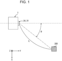
- FIG. 1 is a diagram for explaining an example of how the electronic device according to one embodiment is used.
- FIG. 1 illustrates an example of the electronic device according to one embodiment that has functions of a sensor including a transmission antenna and a reception antenna.
- an electronic device 1 may include a transmission unit and a reception unit that will be described later.
- the transmission unit may include a transmission antenna array 24.
- the reception unit may include a reception antenna array 31.
- FIG. 1 illustrates a circumstance in which, for easier view, the electronic device 1 includes the transmission antenna array 24 and the reception antenna array 31.
- the electronic device 1 may include, as appropriate, at least any of other functionalities, such as at least a part of a signal processing unit 10 ( FIG. 2 ) included in the electronic device 1.
- the electronic device 1 may be configured such that at least any of other functionalities, such as at least a part of the signal processing unit 10 ( FIG. 2 ) included in the electronic device 1, is provided outside the electronic device 1.
- the electronic device 1 may be moving, or be stationary without moving.
- the example illustrated in FIG. 1 gives a simplified view of the transmission unit including the transmission antenna array 24 and the reception unit including the reception antenna array 31 of the electronic device 1.
- the electronic device 1 may include a plurality of transmission units and a plurality of reception units.
- the transmission unit may include the transmission antenna array 24 made up of a plurality of transmission antennas.
- the reception unit may include the reception antenna array 31 made up of a plurality of reception antennas.
- a position where the transmission unit and/or the reception unit is/are installed in or on the electronic device 1 is not limited to the position illustrated in FIG. 1 but may be any other position.
- the number of transmission units and/or the number of reception units may be any number equal to or greater than one, depending on various conditions (or requirements) such as a heartbeat detection range and/or a heartbeat detection accuracy to be achieved by the electronic device 1.
- the electronic device 1 transmits an electromagnetic wave as a transmission wave from the transmission antenna array 24.
- a predetermined object entity for example, a subject 200 illustrated in FIG. 1
- the electronic device 1 receives such a reflected wave.
- the electronic device 1 can detect the subject as a target.
- the electronic device 1 including the transmission antenna array 24 may be typically a radar (Radio Detecting and Ranging) sensor configured to transmit and receive a radio wave.
- the electronic device 1 is not limited to a radar sensor.
- the electronic device 1 may be, for example, a sensor based on the LIDAR (Light Detection and Ranging, Laser Imaging Detection and Ranging) technology that uses an optical wave. These sensors can include, for example, patch antennas, etc. Since the RADAR and the LIDAR are known technologies, detailed description thereof will be sometimes omitted, or the description thereof will be sometimes simplified, where appropriate.
- the electronic device 1 may be a sensor that is based on a technology of detecting an object entity by transmitting and receiving a sound wave or an ultrasound wave, for example.
- the electronic device 1 illustrated in FIG. 1 receives, via the reception antenna array 31, the reflected wave coming back due to reflection of the transmission wave transmitted from the transmission antenna array 24. In this way, the electronic device 1 can detect, as the target, the predetermined subject 200 located within a predetermined distance from the electronic device 1. For example, as illustrated in FIG. 1 , the electronic device 1 is capable of measuring a distance L between the electronic device 1 and the predetermined subject 200. The electronic device 1 is capable of measuring a relative velocity between the electronic device 1 and the predetermined subject 200. The electronic device 1 is capable of measuring a direction (an angle of arrival ⁇ ) in which the reflected wave coming from the predetermined subject 200 arrives at the electronic device 1.
- an XY plane may be, for example, a plane substantially parallel to a ground surface.
- a positive Z-axis direction illustrated in FIG. 1 may indicate a vertically upward direction.
- the electronic device 1 may be disposed on a plane parallel to the XY plane.
- the subject 200 may be in a state of, for example, standing on the ground surface substantially parallel to the XY plane.
- the subject 200 may be, for example, a human or the like located in the neighborhood of the electronic device 1.
- the subject 200 may be, for example, a living thing other than a human, such as an animal located in the neighborhood of the electronic device 1.
- the subject 200 may be moving, stopped, or stationary.
- an object entity to be detected by the electronic device 1 includes living things such as a person, a dog, a cat, a horse, and other kinds of animal in addition to non-living things such as any object.
- the object entity to be detected by the electronic device 1 in the present disclosure may include a radar target including a person, an object, and an animal, etc. to be detected using the radar technology.
- an object entity such as the subject 200 located in the neighborhood of the electronic device 1 is assumed to be a human (or an animal).
- the "subject 200” will be referred to also as the "person 200 who is the subject” where appropriate.
- FIG. 1 illustrates a state in which the transmission antenna array 24 of the transmission unit and the reception antenna array 31 of the reception unit are installed on an outer portion of the electronic device 1.
- the transmission antenna array 24 of the transmission unit and/or the reception antenna array 31 of the reception unit may be installed at various positions of the electronic device 1.
- the transmission antenna array 24 of the transmission unit and/or the reception antenna array 31 of the reception unit may be installed inside the electronic device 1 so as not to appear on the exterior of the electronic device 1.
- the transmission antenna of the electronic device 1 is assumed to transmit a radio wave in a frequency band, such as a millimeter wave (equal to or higher than 30 GHz) or a quasi-millimeter wave (for example, around 20 GHz to 30 GHz).
- the transmission antenna of the electronic device 1 may transmit a radio wave having a frequency bandwidth of 4 GHz such as, for example, from 77 GHz to 81 GHz.
- FIG. 2 is a functional block diagram schematically illustrating an example of a configuration of the electronic device 1 according to one embodiment. An example of the configuration of the electronic device 1 according to one embodiment will be described below.
- FM-CW radar When a distance or the like is measured by using a millimeter-wave radar, a frequency modulated continuous wave radar (hereinafter abbreviated as "FM-CW radar") is often used.
- the FM-CW radar sweeps a frequency of a to-be-transmitted radio wave to generate a transmission signal. Therefore, the frequency of a radio wave used by, for example, a 79-GHz millimeter-wave FM-CW radar has a frequency bandwidth of 4 GHz such as from, for example, 77 GHz to 81 GHz.
- the radar in the frequency band of 79 GHz has a feature of a wider usable frequency bandwidth, as compared with other millimeter-wave/quasi-millimeter-wave radars in frequency bands of, for example, 24 GHz, 60 GHz, 76 GHz, and the like. Such an embodiment will be described below as an example.
- the FM-CW radar scheme used in the present disclosure may include an FCM (Fast-Chirp Modulation) scheme, in which chirp signals are transmitted in a shorter cycle than usual.
- the signal generated by the electronic device 1 is not limited to a signal of the FM-CW scheme.
- the signal generated by the electronic device 1 may be a signal of various schemes other than the FM-CW scheme.
- a transmission signal sequence stored in any storage unit may differ from one to another of these various schemes. For example, in the case of a radar signal of the FM-CW scheme described above, a signal whose frequency increases/decreases for each time sample may be used.
- a more detailed description of the various schemes described above is omitted because known techniques can be employed as appropriate.
- the electronic device 1 includes the signal processing unit 10.
- the signal processing unit 10 may include a signal generation processing unit 11, a reception signal processing unit 12, a heartbeat extraction unit 13, and a calculation unit 14.
- the heartbeat extraction unit 13 may perform processing of, for example, extracting micro-Doppler components.
- the heartbeat extraction unit 13 may perform processing of extracting an envelope of cardiac sound of the person 200 who is the subject.
- the calculation unit 14 may perform processing of, for example, extracting a heart rate interval (RRI) of the person 200 who is the subject.
- the calculation unit 14 may perform processing for frequency analysis of time-series data of the extracted heart rate interval of the person 200 who is the subject.
- the calculation unit 14 may perform processing of calculating a heart rate variability of the person 200 who is the subject.
- cardiac sound may be, for example, an oscillation waveform (see FIG. 20 , etc.) of the chest observed directly using a radar, or chest oscillations.
- Heartbeat is cardiac pulsation itself. The heart rate interval, the number of heart beats, and the like may be calculated from heartbeat behaviors.
- the electronic device 1 includes, as the transmission unit, a transmission DAC 21, a transmission circuit 22, a millimeter-wave transmission circuit 23, and the transmission antenna array 24.
- the electronic device 1 includes, as the reception unit, the reception antenna array 31, a mixer 32, a reception circuit 33, and a reception ADC 34.
- the electronic device 1 according to one embodiment may be configured not to include at least any of the functional units illustrated in FIG. 2 or may include a functional unit(s) other than the functional units illustrated in FIG. 2 .
- the electronic device 1 illustrated in FIG. 2 may be configured using a circuit that has a configuration that is basically the same as or similar to that of an ordinary radar using an electromagnetic wave such as a millimeter-band wave.
- signal processing performed by the signal processing unit 10 may include processing different from that of an ordinary radar of related art.
- the signal processing unit 10 of the electronic device 1 is capable of performing control on the overall operation of the electronic device 1, besides control on each functional unit of the electronic device 1. Among them, the signal processing unit 10 performs various kinds of processing on signals dealt with by the electronic device 1. To provide control and processing capabilities for executing various functions, the signal processing unit 10 may include at least one processor such as, for example, a CPU (Central Processing Unit) or a DSP (Digital Signal Processor).
- the signal processing unit 10 may be collectively embodied by one processor, may be embodied by some processors, or may be embodied by discrete individual processors.
- the processor may be embodied as a single integrated circuit. The integrated circuit is also referred to as "IC".
- the processor may be embodied as a plurality of integrated circuits and discrete circuits connected communicably.
- the processor may be embodied based on various other known technologies.
- the signal processing unit 10 may be configured as, for example, a CPU(s) (hardware) and a program(s) (software) run by the CPU.
- the signal processing unit 10 may include, as appropriate, a storage unit (memory) necessary for operation of the signal processing unit 10.
- the signal generation processing unit 11 of the signal processing unit 10 generates a signal to be transmitted from the electronic device 1.
- the signal generation processing unit 11 may generate a transmission signal such as, for example, a chirp signal (transmission chirp signal).
- the signal generation processing unit 11 may generate a signal (linear chirp signal) whose frequency changes linearly in a periodic manner.
- the signal generation processing unit 11 may generate a chirp signal whose frequency increases linearly in a periodic manner from 77 GHz to 81 GHz as time elapses.
- the signal generation processing unit 11 may generate a signal whose frequency repeats a linear increase (up-chirp) from 77 GHz to 81 GHz and a decrease (down-chirp) in a periodic manner as time elapses.
- the signal generated by the signal generation processing unit 11 may be preset at the signal processing unit 10.
- the signal generated by the signal generation processing unit 11 may be pre-stored in any storage unit or the like of the signal processing unit 10. Since a chirp signal used in a technical field of a radar and the like is known, detailed description thereof will be omitted, or the description thereof will be simplified, where appropriate.
- the signal generated by the signal generation processing unit 11 is supplied to the transmission DAC 21. Therefore, the signal generation processing unit 11 may be connected to the transmission DAC 21.
- the transmission DAC (digital-to-analog converter) 21 has a function of converting a digital signal supplied from the signal generation processing unit 11 into an analog signal.
- the transmission DAC 21 may include an ordinary digital-to-analog converter.
- the signal having been converted into an analog format by the transmission DAC 21 is supplied to the transmission circuit 22. Therefore, the transmission DAC 21 may be connected to the transmission circuit 22.
- the transmission circuit 22 has a function of converting the signal having been converted into the analog format by the transmission DAC 21 into a signal of an intermediate frequency (IF) band.
- the transmission circuit 22 may include an ordinary IF-band transmission circuit.
- the signal having been processed by the transmission circuit 22 is supplied to the millimeter-wave transmission circuit 23. Therefore, the transmission circuit 22 may be connected to the millimeter-wave transmission circuit 23.
- the millimeter-wave transmission circuit 23 has a function of transmitting, as a millimeter wave (RF wave), the signal having been processed by the transmission circuit 22.
- the millimeter-wave transmission circuit 23 may include an ordinary millimeter-wave transmission circuit.
- the signal having been processed by the millimeter-wave transmission circuit 23 is supplied to the transmission antenna array 24. Therefore, the millimeter-wave transmission circuit 23 may be connected to the transmission antenna array 24.
- the signal having been processed by the millimeter-wave transmission circuit 23 is supplied to the mixer 32, too. Therefore, the millimeter-wave transmission circuit 23 may be connected to the mixer 32, too.
- the transmission antenna array 24 is an array of the plurality of transmission antennas. In FIG. 2 , the configuration of the transmission antenna array 24 is simplified. The transmission antenna array 24 transmits the signal having been processed by the millimeter-wave transmission circuit 23 to the outside of the electronic device 1.
- the transmission antenna array 24 may include a transmission antenna array used in an ordinary millimeter-wave radar.
- the electronic device 1 includes a transmission antenna (the transmission antenna array 24) and is capable of transmitting a transmission signal (for example, a transmission chirp signal) as a transmission wave from the transmission antenna array 24.
- a transmission signal for example, a transmission chirp signal
- an object entity such as the person 200 who is the subject is located in the neighborhood of the electronic device 1.
- the object entity such as the person 200 who is the subject reflects at least a part of a transmission wave transmitted from the transmission antenna array 24.
- At least a part of the transmission wave transmitted from the transmission antenna array 24, the part being reflected off the object entity such as the person 200 who is the subject, can come back toward the reception antenna array 31.
- the reception antenna array 31 receives the reflected wave.
- the reflected wave mentioned here may be at least a part of a reflection, of the transmission wave transmitted from the transmission antenna array 24, reflected off the object entity such as the person 200 who is the subject.
- the reception antenna array 31 is an array of the plurality of reception antennas. In FIG. 2 , the configuration of the reception antenna array 31 is simplified. The reception antenna array 31 receives the reflected wave coming back due to reflection of the transmission wave transmitted from the transmission antenna array 24.
- the reception antenna array 31 may include a reception antenna array used in an ordinary millimeter-wave radar. The reception antenna array 31 supplies the reception signal received as the reflected wave to the mixer 32. Therefore, the reception antenna array 31 may be connected to the mixer 32.
- the mixer 32 performs conversion, into an intermediate frequency (IF) band, of the signal (transmission signal) having been processed by the millimeter-wave transmission circuit 23 and the reception signal having been received by the reception antenna array 31.
- the mixer 32 may include a mixer used in an ordinary millimeter-wave radar.
- the mixer 32 supplies a signal generated as a result of mixing to the reception circuit 33. Therefore, the mixer 32 may be connected to the reception circuit 33.
- the reception circuit 33 has a function of performing analog processing on the signal having been converted into the IF band by the mixer 32.
- the reception circuit 33 may include a reception circuit compliant with ordinary IF-band conversion.
- the signal having been processed by the reception circuit 33 is supplied to the reception ADC 34. Therefore, the reception circuit 33 may be connected to the reception ADC 34.
- the reception ADC (analog-to-digital converter) 34 has a function of converting an analog signal supplied from the reception circuit 33 into a digital signal.
- the reception ADC 34 may include an ordinary analog-to-digital converter.
- the signal having been digitized by the reception ADC 34 is supplied to the reception signal processing unit 12 of the signal processing unit 10. Therefore, the reception ADC 34 may be connected to the signal processing unit 10.
- the reception signal processing unit 12 of the signal processing unit 10 has a function of performing various kinds of processing on the digital signal supplied from the reception DAC 34. For example, based on the digital signal supplied from the reception DAC 34, the reception signal processing unit 12 calculates the distance from the electronic device 1 to the object entity such as the person 200 who is the subject (range measurement). Based on the digital signal supplied from the reception DAC 34, the reception signal processing unit 12 calculates the relative velocity of the object entity such as the person 200 who is the subject in relation to the electronic device 1 (velocity measurement). Based on the digital signal supplied from the reception DAC 34, the reception signal processing unit 12 calculates the angle of azimuth, as viewed from the electronic device 1, of the object entity such as the person 200 who is the subject (angle measurement).
- the reception signal processing unit 12 may receive an input of I/Q-converted data. Upon receiving an input of this kind of data, the reception signal processing unit 12 performs fast Fourier transform in each of a distance (range) direction and a speed (velocity) direction (2D-FFT). After that, the reception signal processing unit 12 performs processing of UART (Universal Asynchronous Receiver Transmitter) and/or CFAR (Constant False Alarm Rate) to remove noise points, thereby suppressing false alarms and making their probabilities constant. Then, the reception signal processing unit 12 performs angle-of-arrival estimation on points satisfying the CFAR criterion to obtain the position of the object entity such as the person 200 who is the subject. Information generated as the results of range measurement, velocity measurement, and angle measurement performed by the reception signal processing unit 12 may be supplied to the heartbeat extraction unit 13.
- UART Universal Asynchronous Receiver Transmitter
- CFAR Constant False Alarm Rate
- the heartbeat extraction unit 13 extracts information regarding a heartbeat from the information having been generated by the reception signal processing unit 12. A more detailed description will be given later about operation of extracting the information regarding a heartbeat by the heartbeat extraction unit 13.
- the information regarding a heartbeat having been extracted by the heartbeat extraction unit 13 may be supplied to the calculation unit 14.
- the calculation unit 14 performs various kinds of calculation processing and/or computation processing, etc. on the information supplied from the heartbeat extraction unit 13 regarding a heartbeat. A more detailed description of the various kinds of calculation processing and/or computation processing, etc. performed by the calculation unit 14 will be given later.
- Various kinds of information having been subjected to the calculation processing and/or the computation processing, etc. by the calculation unit 14 may be supplied to, for example, a communication interface 50 or the like. Therefore, the calculation unit 14 and/or the signal processing unit 10 may be connected to the communication interface 50.
- the various kinds of information having been subjected to the calculation processing and/or the computation processing, etc. by the calculation unit 14 may be supplied to any functional component other than the communication interface 50.
- the communication interface 50 includes an interface configured to output, for example, to an external device 60 or the like, information supplied from the signal processing unit 10.
- the communication interface 50 may output, to the external device 60 or the like, information on at least one selected from the group consisting of the position, velocity, and angle of the object entity such as the person 200 who is the subject as, for example, a signal of CAN (Controller Area Network) or the like.
- the information on at least one selected from the group consisting of the position, velocity, and angle of the object entity such as the person 200 who is the subject may be supplied via the communication interface 50 to the external device 60 or the like. Therefore, the communication interface 50 may be connected to the external device 60 or the like.
- the electronic device 1 may be connected to the external device 60 via the communication interface 50 through wired or wireless connection.
- the external device 60 may include any computer and/or any control device, etc.
- the electronic device 1 according to one embodiment may include the external device 60.
- Various kinds of configuration can be adopted for the external device 60, in accordance with how the information on a heartbeat and/or cardiac sound detected by the electronic device 1 is used. Therefore, a more detailed description of the external device 60 is not given here.
- FIG. 3 is a diagram for explaining an example of chirp signals generated by the signal generation processing unit 11 of the signal processing unit 10.
- FIG. 3 illustrates a structure of one frame with respect to time when an FCM (Fast-Chirp Modulation) scheme is used.
- FIG. 3 illustrates an example of a reception signal conforming to the FCM scheme.
- the FCM is a scheme in which chirp signals denoted by c1, c2, c3, c4, ..., cn in FIG. 3 are repeated at short intervals (equal to or greater than a round-trip time of an electromagnetic wave between the radar and the radar target, calculated from, for example, the maximum ranging distance).
- transmission/reception processing is often performed with division in unit of sub-frames such as those illustrated in FIG. 3 .
- the horizontal axis represents elapsed time and the vertical axis represents frequency.
- the signal generation processing unit 11 generates linear chirp signals whose frequency changes linearly in a periodic manner.
- the individual chirp signals are denoted by c1, c2, c3, c4, ..., cn.
- the frequency of each chirp signal increases linearly as time elapses.
- one sub-frame includes several chirp signals c1, c2, c3, c4, ..., cn. That is, each of sub-frames such as a sub-frame 1 and a sub-frame 2 illustrated in FIG. 3 includes several chirp signals c1, c2, c3, c4, ..., cn.
- one frame (each single frame) includes several sub-frames such as the sub-frames 1, 2, ..., N. That is, one frame illustrated in FIG. 3 includes N sub-frames.
- the one frame illustrated in FIG. 3 may serve as a frame 1, which may be followed by a frame 2, a frame 3, and so on. Similarly to the frame 1, each of these frames may include N sub-frames.
- a frame interval of a predetermined length may be included between frames.
- One frame illustrated in FIG. 3 may have a length of approximately 30 ms to 50 ms, for example.
- the signal generation processing unit 11 may generate a transmission signal as any number of frames.
- FIG. 3 illustration of a part of chirp signals is omitted.
- a relationship between time and frequency of a transmission signal generated by the signal generation processing unit 11 may be stored in, for example, the storage unit or the like of the signal processing unit 10.
- the electronic device 1 may transmit a transmission signal constituted by sub-frames each including a plurality of chirp signals.
- the electronic device 1 according to one embodiment may transmit a transmission signal constituted by frames each including a predetermined number of sub-frames.
- the electronic device 1 is assumed to transmit a transmission signal having a frame structure illustrated in FIG. 3 .
- the frame structure illustrated in FIG. 3 is just an example.
- any number of chirp signals may be included in one sub-frame. That is, in one embodiment, the signal generation processing unit 11 may generate a sub-frame including any number (for example, any plural number) of chirp signals.
- the sub-frame structure illustrated in FIG. 3 is also just an example.
- any number of sub-frames may be included in one frame. That is, in one embodiment, the signal generation processing unit 11 may generate a frame including any number (for example, any plural number) of sub-frames.
- the signal generation processing unit 11 may generate signals having different frequencies.
- the signal generation processing unit 11 may generate a plurality of discrete signals having bandwidths in which frequencies f are different from each other.
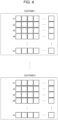
- FIG. 4 is a diagram illustrating a part of the sub-frames of FIG. 3 in a different manner.
- FIG. 4 illustrates each sample of a reception signal obtained as a result of performing two-dimensional fast Fourier transform (2D-FFT), which is processing performed at the reception signal processing unit 12 of the signal processing unit 10 ( FIG. 2 ) when the transmission signal illustrated in FIG. 3 is received.
- 2D-FFT two-dimensional fast Fourier transform
- the chirp signals c1, c2, c3, c4, ..., cn are stored in each sub-frame such as the sub-frame 1, ..., sub-frame N.
- each of the chirp signals c1, c2, c3, c4, ..., cn consists of samples represented by a row of squares arranged in a horizontal direction.
- the reception signal illustrated in FIG. 4 is subjected to 2D-FFT, CFAR, and/or integrated signal processing for each sub-frame, etc. by the reception signal processing unit 12 illustrated in FIG. 2 .
- Fig. 5 is a diagram illustrating an example in which a point group on a range-Doppler (distance-velocity) plane is calculated as a result of performing 2D-FFT, CFAR, and integrated signal processing of the sub-frames at the reception signal processing unit 12 illustrated in Fig. 2 .
- the horizontal direction represents range (distance) and the vertical direction represents velocity.
- a shaded square s1 illustrated in FIG. 5 denotes a point group representing a signal exceeding the threshold of CFAR.
- An unshaded square s2 illustrated in FIG. 5 denotes a bin (2D-FFT sample) without a point group, not exceeding the threshold of CFAR.
- the direction from the radar is calculated by performing direction estimation, and the position and velocity on a two-dimensional plane are calculated as a point group representing the object entity such as the person 200 who is the subject.
- the direction estimation mentioned here may be calculated using a beam former and/or a subspace method. Typical algorithms for the subspace method are: MUSIC (multiple signal classification), ESPRIT (estimation of signal parameters via rotation invariance technique), and the like.
- FIG. 6 illustrates an example of results obtained by transforming point group coordinates from the range-Doppler plane illustrated in FIG. 5 to the XY plane after performing the direction estimation by the reception signal processing unit 12.
- the reception signal processing unit 12 is capable of plotting a point group PG on the XY plane.
- the point group PG is made up of individual points P. Each point P has an angle ⁇ and a velocity Vr in a radial direction in polar coordinates.
- the reception signal processing unit 12 Based on at least the results of 2D-FFT and angle estimation, the reception signal processing unit 12 detects an object entity located in a range in which a transmission wave T is transmitted.
- the reception signal processing unit 12 may perform object detection by performing, for example, clustering processing on the basis of each estimated range information, velocity information, and angle information.
- a known example of algorithms used for data clustering is DBSCAN (density-based spatial clustering of applications with noise). This is an algorithm for performing density-based clustering.
- DBSCAN density-based spatial clustering of applications with noise
- This is an algorithm for performing density-based clustering.
- average power of points constituting the object entity to be detected may be calculated.
- the range information, the velocity information, the angle information, and the power information regarding the object entity detected by the reception signal processing unit 12 may be supplied to, for example, the external device 60, etc. via the communication interface 50.
- the electronic device 1 may include a transmission antenna(s) (the transmission antenna array 24), a reception antenna(s) (the reception antenna array 31), and the signal processing unit 10.
- the transmission antenna array 24 transmits a transmission wave T.
- the reception antenna array 31 receives a reflected wave R that is the transmission wave T having been reflected. Then, based on a transmission signal transmitted as the transmission wave T and a reception signal received as the reflected wave R, the signal processing unit 10 detects an object entity (for example, the object entity such as the person 200 who is the subject) that reflects the transmission wave T.
- an object entity for example, the object entity such as the person 200 who is the subject
- FIG. 7 is a diagram for explaining the configuration of the reception antenna array 31 of the electronic device 1 according to one embodiment, and explaining the principle of estimating the direction of an arrival wave by the reception antenna array 31.
- FIG. 7 illustrates an example of receiving a radio wave by the reception antenna array 31.
- the reception antenna array 31 may be an array of sensors such as reception antennas arranged in a straight line. As illustrated in FIG. 7 , in one embodiment, the reception antenna array 31 may include a plurality of reception antennas arranged in a straight line. In FIG. 7 , small circles represent a plurality of antennas such as antennas x 1 , x 2 , x 3 , ..., x M of the reception antenna array 31.
- the reception antenna array 31 may include any plurality of antennas. As illustrated in FIG. 7 , the plurality of antennas constituting the reception antenna array 31 are arranged at intervals of an array pitch d.
- a sensor array in which sensors (antennas, ultrasonic transducers, microphones, or the like) corresponding to various physical waves are arranged to form an array as described here is referred to also as a uniform linear array (ULA).
- the physical waves (such as electromagnetic waves or sound waves) arrive from various directions such as, for example, ⁇ 1 and ⁇ 2 .
- the directions ⁇ 1 and ⁇ 2 mentioned here may be the angles of arrival described above.
- the sensor array such as the reception antenna array 31 is capable of estimating the direction of arrival (angle of arrival) by using a phase difference caused between measured values of the sensors in accordance with the directions of arrival of the physical waves.
- the method of estimating the direction of arrival of a wave as described here is referred to also as angle-of-arrival estimation or direction-of-arrival estimation (DoA).
- At least one of the transmission antenna array 24 or the reception antenna array 31 may be a linear array of a plurality of antennas. This enables directivity to be narrowed appropriately when transmitting/receiving a radio wave at, for example, a millimeter-wave radar.
- a beam former is often used for controlling the direction of a transmission beam.
- a subspace method (the above-mentioned MUSIC, ESPRIT, etc.) is often used, rather than a beam former, for estimating the direction of arrival of the reflected wave.
- phase difference arises between measured values of the sensors of the ULA illustrated in FIG. 7 in accordance with the directions of arrival. Therefore, utilizing the phase difference enables estimating the direction of arrival of the reflected wave.
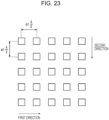
- FIG. 8 is a diagram illustrating an example of antenna arrangement for direction-of-arrival estimation for two orthogonal angles.
- the transmission antenna array 24 and/or the reception antenna array 31 may include an array of a plurality of patch antenna units.
- one patch antenna unit may include a plurality of elements connected electrically in a first direction illustrated therein.
- the plurality of elements may be connected electrically via wiring such as, for example, a strip line on a substrate.
- the plurality of elements may be spaced apart from one another by an interval d 1, t , which is shorter than a half of a wavelength ⁇ of a transmission wave.
- any number, two or more, of elements may be electrically connected to configure each patch antenna unit.
- the transmission antenna array 24 may be an array of the plurality of patch antenna units arranged in a second direction illustrated therein.
- the patch antenna units may be spaced apart from one another by an interval d 2, t , which is shorter than a half of the wavelength ⁇ of the transmission wave.
- the transmission antenna array 24 may include any number, two or more, of patch antenna units.
- the reception antenna array 31 may have a layout in which the arrangement of the plurality of elements in the transmission antenna array 24 is altered. That is, in the reception antenna array 31 illustrated in FIG. 8 , one patch antenna unit may include a plurality of elements connected electrically in the second direction illustrated therein. In each patch antenna unit, the plurality of elements may be connected electrically via wiring such as, for example, a strip line on the substrate. In each patch antenna unit, the plurality of elements may be spaced apart from one another by an interval d 2, s , which is shorter than a half of the wavelength ⁇ of the transmission wave. In FIG. 8 , any number, two or more, of elements may be electrically connected to configure each patch antenna unit.
- the reception antenna array 31 may be an array of the plurality of patch antenna units arranged in the first direction illustrated therein.
- the patch antenna units may be spaced apart from one another by an interval d 1, s , which is shorter than a half of the wavelength ⁇ of the transmission wave.
- the reception antenna array 31 may include any number, two or more, of patch antenna units.
- All of the elements included in the transmission antenna array 24 and the reception antenna array 31 may be disposed on the same plane (for example, on a surface layer of the same substrate).
- the transmission antenna array 24 and the reception antenna array 31 may be disposed in proximity to each other (monostatic).
- the first direction and the second direction illustrated in FIG. 8 may be geometrically orthogonal to each other.
- the transmission antenna array 24 and the reception antenna array 31 illustrated in FIG. 8 make it possible to narrow the respective directivities of the transmission antennas and the reception antennas appropriately.
- a beam former in the second direction illustrated in FIG. 8 can be realized by using the transmission antenna array 24 illustrated in FIG. 8 to control the direction of transmitting each transmission wave at each timing of transmitting the transmission wave (transmission signal).
- Using the reception antenna array 31 illustrated in FIG. 8 realizes estimation of the direction of arrival of a reflected wave regarding the first direction illustrated in FIG. 8 . In this way, the direction of arrival of the reflected wave can be estimated regarding the two angles that are substantially orthogonal to each other. Therefore, a point group indicating the object entity such as the person 200 who is the subject can be acquired in a three-dimensional manner.
- the electronic device 1 transmits a transmission wave such as a millimeter-wave radar toward the person 200 who is the subject, and measures (estimates) the heartbeat of the person 200 who is the subject on the basis of a result of receiving a wave reflected off the chest where the heart of the person 200 who is the subject exists.
- the subject 200 may be a human or an animal.
- components expected to draw an envelope of a heartbeat can be extracted by, for example, performing frequency filtering on oscillations at the position where the presence of the person 200 who is the subject is detected by means of a radar.
- an interval between a peak and another peak of the envelope is defined as a heart rate interval; this enables calculation of an approximate value of the heart rate interval.
- Approximation of a peak on an envelope of a heartbeat to an R peak in an electrocardiogram can be employed here. Therefore, similarly to the terms used in electrocardiography and the like, the "heart rate interval" is referred to also as an RR interval or RRI.
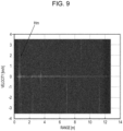
- FIG. 9 is a diagram illustrating an example of the result of 2D-FFT performed by receiving a reflected wave of a transmission wave transmitted toward the person 200 who is the subject.
- FIG. 9 illustrates, as the result of 2D-FFT, a spectrum representing cardiac sound and a body motion of the person 200 who is the subject.
- the horizontal axis represents range and the vertical axis represents velocity.
- the signal processing unit 10 (for example, the heartbeat extraction unit 13) of the electronic device 1 according to one embodiment may, for example, extract a peak Hm illustrated in FIG. 9 as a body motion such as a heartbeat of the person 200 who is the subject.
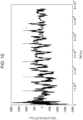
- FIG. 10 is a diagram for explaining a method of detecting peaks on the basis of an envelope waveform of cardiac sound obtained through the frequency filtering described above.
- the graph illustrated in FIG. 10 gives an example of changes over time in the envelope waveform of cardiac sound obtained through the frequency filtering described above.
- the envelope waveform of FIG. 10 includes many peaks as illustrated therein.
- the beating of the person 200 who is the subject is known to fall within a range of approximately 50 to 130 beats per minute. Therefore, an approximate cardiac sound interval of the person 200 who is the subject can be calculated by selecting, from among many peaks illustrated in FIG. 10 , peaks the time interval between which is within a range from 0.4 second to 0.8 second, which is the reciprocal of the number of beats per minute.
- peaks indicated by down-pointing arrows in FIG. 10 may be selected as the approximate cardiac sound interval of the person 200 who is the subject.
- FIG. 11 is a flowchart illustrating an example of operation for estimating the heart rate interval described above. Described below while referring to FIG. 11 is an overview of the operation for estimating the heart rate interval described above.
- FIG. 11 illustrates the operation performed after receiving the reflected wave by the electronic device 1 according to one embodiment. That is, as the premise on which the operation illustrated in FIG. 11 is based, the electronic device 1 illustrated in FIG. 2 transmits a transmission wave (transmission signal) from the transmission antenna array 24. Then, at least a part of the transmission wave transmitted from the electronic device 1 turns into a reflected wave due to reflection off (the chest of) the person 200 who is the subject. Then, the electronic device 1 illustrated in FIG. 2 receives such a reflected wave via the reception antenna array 31. The operation illustrated in FIG. 11 thereafter starts.
- a transmission wave transmission signal
- step S110 the signal processing unit 10 of the electronic device 1 processes the received signal (reception signal).
- the signal processing performed in step S110 may include, for example, 2D-FFT, CFAR processing, and/or direction-of-arrival estimation described above. This operation may be performed by, for example, the reception signal processing unit 12 of the signal processing unit 10.
- step S120 the signal processing unit 10 extracts the source of oscillations from the information having been processed in step S110.
- the signal processing performed in step S120 may include, for example, processing of performing filtering on data obtained as the result of performing 2D-FFT.
- the signal processing unit 10 may extract spectral components at only the position of presence of the person 200 who is the subject. Various known methods may be used for pinpointing the position of presence of the person 200 who is the subject. This operation may be performed by, for example, the heartbeat extraction unit 13 of the signal processing unit 10.
- step S130 the signal processing unit 10 converts the results of processing having been performed upstream into an oscillation waveform.
- the processing performed in step S130 may include, for example, processing of extracting phase information from IQ data.
- the signal processing unit 10 may extract oscillation data including cardiac sound from the spectral components of 2D-FFT processing of the person 200 who is the subject, which have been extracted in step S120. This operation may be performed by, for example, the heartbeat extraction unit 13 of the signal processing unit 10.
- step S140 the signal processing unit 10 extracts oscillation data from the results of processing having been performed upstream.
- the processing performed in step S140 may include, for example, frequency filtering.
- step S140 by performing frequency filtering, the signal processing unit 10 may extract a low frequency signal including the envelope of cardiac sound of the person 200 who is the subject. This operation may be performed by, for example, the heartbeat extraction unit 13 of the signal processing unit 10.
- step S150 the signal processing unit 10 extracts peaks of the beating of the person 200 who is the subject from the results of processing having been performed upstream.
- the signal processing unit 10 may detect peaks of the low frequency signal including the envelope of cardiac sound of the person 200 who is the subject. This operation may be performed by, for example, the calculation unit 14 of the signal processing unit 10.
- step S160 the signal processing unit 10 calculates the RR interval (RRI) of the person 200 who is the subject from the results of processing having been performed upstream.
- the signal processing unit 10 may calculate each peak-to-peak pitch (interval).
- the signal processing unit 10 may calculate the RRI by extracting the interval between the values of the peaks having been detected in step S150. This operation may be performed by, for example, the calculation unit 14 of the signal processing unit 10.
- step S170 the signal processing unit 10 performs spectrum analysis on the results of processing having been performed upstream.
- the signal processing unit 10 may calculate the heart rate variability (HRV) of the person 200 who is the subject by calculating the spectral density of time-series data of the RRI.
- HRV heart rate variability
- For calculating the power spectral density of the time-series data of the RRI for example, Welch's method or the like may be used. This operation may be performed by, for example, the calculation unit 14 of the signal processing unit 10.
- the electronic device 1 by performing frequency filtering on oscillations at the position where the person 200 who is the subject is present, extracts components expected to draw an envelope of a heartbeat, and calculate an interval between peaks of the envelope as a heart rate interval. In this way, the electronic device 1 according to one embodiment is capable of calculating an approximate heart rate interval of the person 200 who is the subject.
- the electronic device 1 features a further improvement on the method described above. Toward this improvement, the electronic device 1 according to one embodiment analyzes cardiac sound itself to extract an accurate heart rate interval, for example, by extracting the cardiac sound by means of a radar using a high frequency band of a millimeter wave or higher. This method will be described below.
- the electronic device 1 performs appropriate signal processing in an appropriate sequential order on a signal (chirp signal) that the electronic device 1 receives, thereby narrowing down a subspace where signal components of cardiac sound of the person 200 who is the subject exists, and a subspace basis.
- the electronic device 1 may, in a linear space where a signal of cardiac sound of the person 200 who is the subject exists, adopt different basis vectors, and may extract a subspace based on respective coordinates while describing a space using an appropriate coordinate system. Through this processing, the electronic device 1 according to one embodiment is capable of searching for a subspace where cardiac sound of the person 200 who is the subject exists.
- a coordinate system of a space having been subjected to 2D-FFT processing a coordinate system of a time-series signal taken through contraction of a chirp signal timewise, a coordinate system based on a Fourier transform thereof, or a coordinate system based on continuous/discrete wavelet, etc. may be used.
- the electronic device 1 may perform the following characteristic processing on a received signal through step-by-step procedures.
- the characteristic processing performed by the electronic device 1 according to one embodiment will be described schematically in order below.
- an appropriate window function is applied to 2D-FFT processing of a received chirp signal, and, in addition, micro-Doppler components only of a point group of the presence of the person 200 who is the subject are extracted through direction-of-arrival estimation.
- principal component analysis and/or singular value decomposition, etc. of a set of time-series waveforms of oscillations having been extracted in the first step is/are performed on the micro-Doppler signal.
- frequency filtering is performed by using at least one selected from the group consisting of short-time Fourier transform, continuous wavelet transform, and bandpass filtering.
- cardiac sound is extracted by performing multi-resolution analysis based on discrete wavelet transform by applying an appropriate wavelet function and an appropriate scaling function to the cardiac sound.
- the electronic device 1 by acquiring an envelope waveform of cardiac sound obtained through the processing in each of the above-described steps, its positive/negative peaks can be detected, and the RRI can be calculated with high accuracy by appropriately calculating the interval between the peaks.
- the method for acquiring the envelope waveform for example, envelope waveform calculation based on continuous wavelet transform or Hilbert transform, etc. may be used.
- FIG. 12 is a flowchart illustrating an example of operation performed by the electronic device 1 according to one embodiment.
- FIG. 13 is a flowchart illustrating an example of operation in step S15 of FIG. 12 in more detail. A flow of operation performed by the electronic device 1 according to one embodiment will be described schematically below while referring to FIGs. 12 and 13 .
- Step S11 of FIG. 12 can be executed in the same manner as in the operation in step S 110 illustrated in FIG. 11 , or in a similar manner. That is, upon the start of the operation illustrated in FIG. 12 , first, in step S11, the signal processing unit 10 of the electronic device 1 processes the received signal (reception signal).
- the signal processing performed in step S11 may include, for example, 2D-FFT, CFAR processing, and/or direction-of-arrival estimation described above. This operation may be performed by, for example, the reception signal processing unit 12 of the signal processing unit 10.
- step S12 the signal processing unit 10 extracts the source of oscillations from the information having been processed in step S11.
- the processing of extracting the source of oscillations in step S12 may be different from the processing of extracting the source of oscillations in step S120 illustrated in FIG. 11 .
- the signal processing unit 10 may extract only the region of presence of the person 200 who is the subject, by means of an appropriate window function, on the range-Doppler plane having been calculated through 2D-FFT.
- the signal processing unit 10 may use, as the window function, for example, a hanning window, a hamming window, a Blackman-Harris window, or the like.
- the signal processing unit 10 may perform extraction of the source of oscillations including a body motion including cardiac sound and/or respiration of the person 200 who is the subject on the basis of, for example, the following steps.
- the signal processing unit 10 classifies a point group exceeding the threshold of CFAR on the range-Doppler plane into areas of angles having been determined in advance. For example, classification into areas A to C of the following angles may be performed, where ⁇ denotes an angle on an xy plane illustrated in FIG. 6 :
- the signal processing unit 10 applies clustering to, among those in a certain angular area group into which the classification has been performed in the first step, the point group exceeding the threshold of CFAR on the range-Doppler plane, as labeled as s1 in FIG. 5 .
- clustering For example, a DBSCAN method or the like may be used for the clustering performed here.
- the signal processing unit 10 compares, for the l-th cluster, a deviation D dev [l] in the number of bins in the Doppler direction with a certain formula value D dev, th . As the result of this comparison, the signal processing unit 10 determines only those for which D dev [l] ⁇ D dev, th holds as the person 200 who is the subject, and sets flag HF[l] ON for them. That is, for example, the signal processing unit 10 may perform the following processing using a pseudo code:
- the signal processing unit 10 may perform subsequent processing for only regions of clusters for which the flag HF[l] of the person 200 who is the subject indicates 1.
- the signal processing unit 10 is capable of extracting oscillations including cardiac sound, respiration, and/or a body motion of the person 200 who is the subject.
- the operation described above may be performed by, for example, the reception signal processing unit 12 or the heartbeat extraction unit 13 of the signal processing unit 10.
- step S13 the signal processing unit 10 extracts elements of oscillations from information on the source of oscillations having been extracted in step S12.
- the signal processing unit 10 performs singular value decomposition (SVD) for removing signal noise in a pre-processed manner.
- the signal processing unit 10 may remove noise whose energy is low.
- the signal processing unit 10 may remove oscillation data having crept in due to Fourier transform uncertainty (i.e., oscillation data except those lying at desired positions illustrated in FIG. 9 ).
- the operation described above may be performed by, for example, the reception signal processing unit 12 or the heartbeat extraction unit 13 of the signal processing unit 10.
- step S14 can be executed in the same manner as in the operation in step S130 illustrated in FIG. 11 , or in a similar manner. That is, in step S14, the signal processing unit 10 converts the results of processing having been performed upstream into an oscillation waveform.
- the processing performed in step S14 may include, for example, processing of extracting phase information from IQ data. This operation may be performed by, for example, the reception signal processing unit 12 or the heartbeat extraction unit 13 of the signal processing unit 10.
- step S13 The processing performed in step S13 and step S14 will now be further described.
- S vib be a received chirp signal set having been extracted on the 2D-FFT plane.
- a result expressed by Formula (1) shown below can be obtained by performing singular value decomposition of S vib .
- S vib U ⁇ V * ⁇ C N ⁇ M
- U denotes a matrix of left-singular vectors
- ⁇ denotes a matrix in which singular values are arranged diagonally
- V denotes a matrix in which right-singular vectors are arranged.
- * denotes Hermitian transpose.
- N denotes the number of samples in one chirp signal
- M denotes the number of chirp snapshots.
- FIG. 14 is a diagram illustrating an example of a relationship between a rank of a desired signal and a rank of a noise signal in singular value decomposition.
- a signal p ext expressed by Formula (3) shown below is generated by finding a sum total based on the total number N of samples, or a part of the samples, in one chirp signal of S ext .
- the signal p ext represents micro-Doppler.
- the results of SVD are arranged in a descending order of singular values (corresponding to energy), with the horizontal axis representing ranks and the vertical axis representing the singular values.
- a concept that a signal of a certain singular value or greater is always a desired signal is adopted.
- a singular-value-rank boundary defining whether a certain signal is a desired signal or not lies at a border portion of a rank region up to 30 inclusive, which is indicated by a dark gray section in the graph of FIG. 14 .
- the section corresponding to the rank region up to 30 inclusive is the region of the desired signal.
- the desired-signal rank section lies from 1 inclusive to 30 inclusive. In the present disclosure, therefore, it follows that singular vectors corresponding to left/right singular values of the rank region from 1 inclusive to 30 inclusive are taken out.
- the desired-signal rank section lies from 1 inclusive to 30 inclusive.
- the maximum rank value may be determined empirically.
- the maximum rank value (in the present disclosure, the rank 30) may be determined using a statistical method.
- the singular value takes a nosedive at the rank 130, and signals beyond this rank are basically defined as noise. Therefore, the signals beyond this rank are not needed.
- the left/right-singular vectors corresponding to the singular values in the area of the rank 31 to 130 slightly contain some desired signal components, too.
- the principal causes of these left/right-singular vectors seem to be unnecessary micro oscillations, and/or artificial noises (artifacts) produced by signal processing of the radar, etc. Therefore, these elements may be disregarded.
- p ext ⁇ n 1 ⁇ n ⁇ n 2 S ext n m ⁇ C M
- step S15 illustrated in FIG. 12 the signal processing unit 10 extracts cardiac sound, RRI, and/or HRV, etc. from the results of processing in step S14.
- Step S15 includes several kinds of signal processing.
- a flowchart in FIG. 13 illustrates the signal processing performed in step S15 of FIG. 12 in more detail. The operation or processing illustrated in FIG. 13 may be performed by, for example, the calculation unit 14 of the signal processing unit 10. The operation or processing illustrated in FIG. 13 will now be further described below.
- step S21 the signal processing unit 10 performs processing for removing noise (denoising).
- Various methods may be used for the denoising performed in step S21.
- the signal processing unit 10 may perform the denoising of a time-series waveform using, for example, an empirical Bayes method, a wavelet method, or the like.
- step S22 the signal processing unit 10 extracts a desired signal waveform (cardiac sound waveform) by using a discrete wavelet method such as a maximum overlap discrete Wavelet transform (MODWT).
- a discrete wavelet method such as a maximum overlap discrete Wavelet transform (MODWT).
- step S21 and/or step S22 will now be further described.
- step S21 the signal processing unit 10 further performs preprocessing for removing unwanted noise on a signal velocity vector v ext .
- the signal processing unit 10 may perform the denoising based on band limitation using an empirical Bayes method, a continuous wavelet, or the like. In step S21, the signal processing unit 10 may perform the denoising based on frequency subtraction using a noise profile on artifact noise, etc. arising from nonlinear processing from step S11 to step S14 in FIG. 12 .
- the signal processing unit 10 may perform multi-resolution analysis based on discrete wavelet transform by applying a wavelet waveform similar to a cardiac sound waveform to the preprocessed denoised signal. In this way, in step S22, the signal processing unit 10 extracts only a subspace in the level of multi-resolution analysis where cardiac sound of the person 200 who is the subject exists empirically. In this way, in step S22, the signal processing unit 10 may extract the cardiac sound of the person 200 who is the subject. Specifically, the signal processing unit 10 may use maximum overlap multi-resolution analysis (MODWT) or the like in order to enhance temporal resolution.
- MODWT maximum overlap multi-resolution analysis
- a wavelet basis suitable for extraction of a heartbeat may be, for example, Symlet, Daubechies, and the like. The order of them may be set appropriately.
- FIG. 15 is a diagram that conceptually illustrates multi-resolution analysis based on discrete wavelet transform.
- the signal processing unit 10 can obtain a cardiac sound waveform h through reconfiguration by limiting an empirically suitable level to j 0 ⁇ N in Formula (6) shown below.
- the cardiac sound waveform h obtained from Formula (6) shown above indicates the cardiac sound of the person 200 who is the subject with high precision (see FIGs. 19 and 20 to be described later). This result indicates that accuracy that is high enough for use for medical examination of cardiac sound and the like on an as-is basis can be expected.
- step S23 the signal processing unit 10 detects the peaks of cardiac sound by using a scalogram.
- the signal processing unit 10 detects the power (level) of the peak at each point in time. The point in time where cardiac sound is positioned is detected as the position of the peak.
- step S23 the signal processing unit 10 detects (extracts) the peaks in energy of the desired signal (cardiac sound waveform) having been extracted in step S22. Therefore, the signal processing unit 10 extracts an envelope waveform by using the scalogram through continuous wavelet transform and by performing rendering into one dimension thereof.
- the signal processing unit 10 obtains the scalogram through the continuous wavelet transform.
- the signal processing unit 10 obtains a one-dimension waveform by finding the maximum value in the frequency-axis direction at each point in time on the scalogram.
- FIGs. 16 and 17 are diagrams for explaining the multi-resolution analysis based on the discrete wavelet transform.
- FIG. 16 is a diagram illustrating an example of the scalogram of the cardiac sound waveform h.
- FIG. 17 is a diagram illustrating an example of a one-dimension-rendered scalogram of the cardiac sound waveform h illustrated in FIG. 16 .
- Sh(m) denotes the m-th element in the rendering, to one dimension, of the scalogram of the cardiac sound waveform h illustrated in FIG. 17
- f denotes each frequency of the scalogram.
- step S24 the signal processing unit 10 controls the roughness of the peaks of the scalogram.
- the signal processing unit 10 in order to appropriately calculate the peaks of the envelope waveform of the cardiac sound having been extracted in step S23, the signal processing unit 10 further removes high-frequency components by means of an appropriate range. Therefore, the signal processing unit 10 may adjust the smoothness of the envelope by performing discrete wavelet transform using a Haar wavelet or like.
- the signal processing unit 10 may perform signal reconfiguration by using multi-resolution analysis based on discrete wavelet transform on a vector s h having been calculated as the envelope waveform of the cardiac sound for the purpose of adjusting its smoothness.
- a wavelet basis suitable to be used here may be a Haar wavelet.
- the concept of multi-resolution decomposition may be, for example, the same as or similar to that of FIG. 15 .
- the formula for reconfiguration of multi-resolution decomposition may be, for example, the same as or similar to that of Formula (6) shown above.
- a reference sign s h,rc will be used hereinafter for the vector obtained by reconfiguring the vector s h having been calculated as the envelope waveform of the cardiac sound.
- step S25 the signal processing unit 10 pinpoints the positions of a first cardiac sound and a second cardiac sound that have been made clear through the processing up to step S25.
- the signal processing unit 10 may pickup the first cardiac sound S 1 and the second cardiac sound S2 in the cardiac sound and may perform pairing of the first cardiac sound S 1 and the second cardiac sound S2.
- the signal processing unit 10 may perform pairing of the first cardiac sound S1 and the second cardiac sound S2 in order to measure the interval between the first cardiac sounds S1 accurately.
- the signal processing unit 10 may perform peak detection for every peak of s h,rc .
- FIG. 18 is a diagram illustrating an example of execution of peak detection of a heartbeat envelope waveform.
- the signal processing unit 10 may create a row vector l s1,s2 ⁇ R K of a time list by executing the peak detection illustrated in FIG. 18 .
- DBSCAN which is a clustering algorithm
- the signal processing unit 10 sets, as 1, minPts (the minimum number of neighboring data points other than the self), which is a parameter of DBACAN.
- the signal processing unit 10 measures ⁇ (distance between neighboring data points), which is a parameter of DBACAN, in terms of time. In this way, the signal processing unit 10 sets a standard time interval for the first cardiac sound S1 and the second cardiac sound S2 as a numerical value measured in terms of time to 0.2 to 0.4 seconds or so.
- the signal processing unit 10 adds a second row to the row vector l s1,s2 , and creates a list matrix L s1,s2 by assigning its row cluster number (natural number of pair number 1 or greater) to the first cardiac sound S1 and by assigning a numerical value 0 to the second cardiac sound S2.
- the signal processing unit 10 is capable of, in the list matrix L s1,s2 , identify the first cardiac sound S1 clearly, and indicate its order clearly.
- the signal processing unit 10 may list the non-paired peak as S1.
- step S26 the signal processing unit 10 calculates the heart rate interval RRI.
- the signal processing unit 10 may calculate the RRI by calculating the interval between the peaks having been paired first in step S25, that is, the interval between the first cardiac sounds S1.
- the signal processing unit 10 calculates the RRI by finding the interval between two adjacent S1 in the list matrix L s1,s2 .
- the RRI time-series data calculated here is expected to have outliers.
- the outlier can be generated due to, for example, a non-detection of the first cardiac sound S1, a mix-up between the first cardiac sound S1 and the second cardiac sound S2, and any other reason such as the influence of noise caused by a significant body motion, etc. Therefore, in one embodiment, the signal processing unit 10 may perform correction processing to deal with the above circumstances.
- the signal processing unit 10 may use a method based on Bayes' estimation such as a Kalman filter for the correction processing. Heartbeat response is nonlinear, and plant modeling is thus physically difficult. Therefore, in step S26, the signal processing unit 10 may perform correction processing based on a statistical method such as an unscented Kalman filter (UKF).
- a linear Kalman filter may be used approximatively, or an extended Kalman filter (EKF) may be used by modeling the transit of the heart rate interval by an empirical modeling approach.
- EKF extended Kalman filter
- the data obtained in step S26 may be RRI time-series data s RRI .
- step S27 the signal processing unit 10 performs spectrum analysis.
- the signal processing unit 10 may calculate a spectrogram of RRI (HRV).
- the signal processing unit 10 may calculate the power spectral density of the time-series data of the RRI by using, for example, Welch's method or the like.
- the signal processing unit 10 may perform FFT calculation and power spectrum calculation for the s RRI in accordance with Welch's method or the like, that is, by means of a window function overlapping timewise. Through this processing, the signal processing unit 10 is capable of obtaining the power spectral density of the RRI (see FIG. 22 to be described later).
- FIG. 19 is a diagram illustrating a time-series waveform of cardiac sound obtained by means of the electronic device 1 according to one embodiment.
- the waveform illustrated in FIG. 19 may be the cardiac sound waveform h obtained using Formula (6) described above.
- FIG. 20 is an enlarged view of a time span in a region enclosed by a broken-line frame in FIG. 19 .
- the time-series waveform of cardiac sound obtained by means of the electronic device 1 makes it possible to identify the first cardiac sound S1 and the second cardiac sound S2 clearly.
- the time-series waveform of cardiac sound obtained by means of the electronic device 1 according to one embodiment makes it possible to clearly identify the heart rate interval RRI, which is calculated from the interval of the first cardiac sound S1 and the second cardiac sound S2, too.
- RRI and the heart rate interval are not exactly identical to each other, they are believed to match approximatively. Therefore, in the present disclosure, the RRI and the heart rate interval are assumed to indicate the identical thing.
- FIG. 21 is a diagram illustrating an example of the time-series waveform of the RRI illustrated in FIGs. 19 and 20 .
- the result illustrated in FIG. 21 is calculated based on the cardiac sound extracted accurately in FIGS. 19 and 20 . Therefore, the result illustrated in FIG. 21 has accuracy of some milliseconds.
- FIG. 22 is a diagram illustrating the power spectral density of the RRI.
- FIG. 22 is a diagram illustrating an example of the power spectral density calculated using Welch's method from the time-series waveform of the RRI illustrated in FIG. 21 .
- the electronic device 1 makes it possible to calculate the power spectral density of the RRI on the basis of the RRI having accuracy of some milliseconds. Therefore, with the electronic device 1 according to one embodiment, the components from 0.15 Hz to 0.4 Hz, which is called HF of heartbeat PSD, can also be calculated accurately.
- the electronic device 1 makes it possible to obtain, for example, a detailed cardiac sound waveform such as one illustrated in FIGs. 19 and 20 , accurate RRI time-series data such as one illustrated in FIG. 21 , and power spectral density (PSD) of a heart rate interval such as one illustrated in FIG. 22 .
- the electronic device 1 makes it possible to detect a heartbeat in a human body or the like with good accuracy through transmission and reception of a radio wave.
- weak oscillations such as those of a heartbeat in a human body or the like can be detected with good accuracy through transmission and reception of a radio wave such as, for example, a millimeter wave, which is expected to be useful in various fields.
- the layout of the transmission antenna array 24 and/or the reception antenna array 31 of the electronic device 1 is not limited to the layout illustrated in FIG. 8 .
- the reception antenna array 31 of the electronic device 1 may have a configuration illustrated in FIG. 23.
- FIG. 23 is a diagram illustrating an example of a URA (uniform rectangular array) reception antenna.
- the signal processing unit 10 have been described as including functional units such as the heartbeat extraction unit 13 and the calculation unit 14.
- the processing performed by the heartbeat extraction unit 13 and/or the calculation unit 14 may be performed by an external computer, an external processor, or the like.
- step S13 (SVD processing) illustrated in FIG. 12 may be replaced by any other subspace method.
- step S13 the processing in step S13 (SVD processing) illustrated in FIG. 12 may be omitted in a case where a large number can be set for the number of samples N of one chirp or in a case where other noise contamination can be eliminated by means of a hardware method or the like.
- step S24 illustrated in FIG. 13 may be omitted depending on a situation of implementation.
- the RRI may be obtained by calculating the interval between the second cardiac sounds S2 after the pairing of the first cardiac sound S1 and the second cardiac sound S2 in step S25 illustrated in FIG. 13 .
- the electronic device 1 detects weak oscillations such as those of a heartbeat by using, for example, a millimeter-wave sensor including a plurality of transmission antennas and a plurality of reception antennas. If a subject is not detected, the electronic device 1 according to one embodiment detects a body movement of the subject by performing a beamforming pattern of the transmission antennas while changing transmission phases of the antennas. On the other hand, if a body movement of the subject is detected, the electronic device 1 according to one embodiment detects a heartbeat by performing beamforming in a direction of the body movement. As described above, the electronic device 1 according to one embodiment automatically detects a direction of a human body, and thus can improve a signal quality. Therefore, the electronic device 1 according to one embodiment can improve a heartbeat detection accuracy and/or a heartbeat detection range. Therefore, the electronic device 1 according to one embodiment can detect a heartbeat of a human with high accuracy.
- a millimeter-wave sensor including a plurality of transmission antennas and a plurality of reception antennas
- each functional unit, each means, each step, or the like can be added to another embodiment or replaced with each functional unit, each means, each step, or the like in another embodiment without causing any logical contradiction.
- a plurality of functional units, means, steps, or the like may be combined into one or may be divided.
- each embodiment according to the present disclosure described above is not limited to strict implementation in accordance with each description of the embodiment, and may be implemented by appropriately combining the features or omitting a part thereof.
- the embodiments described above are not limited to implementation as the electronic device 1.
- the embodiments described above may be implemented as a method for controlling a device such as the electronic device 1.
- the embodiments described above may be implemented as a program to be run by a device such as the electronic device 1.
- the electronic device 1 has been described as a device that includes components constituting a so-called radar sensor, such as the transmission antenna array 24 and the reception antenna array 31.
- the electronic device according to one embodiment may be implemented as a component such as, for example, the signal processing unit 10.
- the signal processing unit 10 may have a function for processing signals dealt with by the transmission antenna array 24 and the reception antenna array 31.
Landscapes
- Engineering & Computer Science (AREA)
- Health & Medical Sciences (AREA)
- Radar, Positioning & Navigation (AREA)
- Remote Sensing (AREA)
- Physics & Mathematics (AREA)
- Life Sciences & Earth Sciences (AREA)
- Computer Networks & Wireless Communication (AREA)
- General Physics & Mathematics (AREA)
- Biomedical Technology (AREA)
- Heart & Thoracic Surgery (AREA)
- Veterinary Medicine (AREA)
- Public Health (AREA)
- Biophysics (AREA)
- Pathology (AREA)
- General Health & Medical Sciences (AREA)
- Animal Behavior & Ethology (AREA)
- Medical Informatics (AREA)
- Molecular Biology (AREA)
- Surgery (AREA)
- Physiology (AREA)
- Cardiology (AREA)
- Dentistry (AREA)
- Oral & Maxillofacial Surgery (AREA)
- Electromagnetism (AREA)
- Radiology & Medical Imaging (AREA)
- Signal Processing (AREA)
- Nuclear Medicine, Radiotherapy & Molecular Imaging (AREA)
- Radar Systems Or Details Thereof (AREA)
- Measuring Pulse, Heart Rate, Blood Pressure Or Blood Flow (AREA)
- Measurement Of The Respiration, Hearing Ability, Form, And Blood Characteristics Of Living Organisms (AREA)
Abstract
Description
- This application claims priority from
Japanese Patent Application No. 2021-132423 filed in Japan on August 16, 2021 - The present disclosure relates to an electronic device, a method for controlling an electronic device, and a program.
- For example, in fields of automobile-related industries and the like, a technology for measuring a distance between a vehicle of interest and a predetermined object, and the like, is regarded as important. More particularly, various studies have recently been conducted on a radar (Radio Detecting and Ranging) technology for measuring a distance, etc. to an object such as an obstacle by transmitting a radio wave such as a millimeter wave and then receiving a wave reflected off the object. The importance of such a technology for measuring a distance, etc. is expected to grow more and more in the future with progresses of technologies for assisting drivers in driving and autonomous-driving-related technologies for partially or entirely automating driving.
- Various suggestions have been made regarding a technology for detecting the presence, etc. of a predetermined object by receiving a reflected wave coming back from the object due to reflection of a transmitted radio wave. For example,
Patent Literature 1 has proposed a device capable of detecting the presence of a person and biological information on the person by utilizing a microwave. As another example,Patent Literature 2 has proposed an apparatus for detecting a vital sign such as a frequency of respiration of a living body or a heartbeat thereof on the basis of a reflected signal of a microwave radar. -
- Patent Literature 1:
Japanese Unexamined Patent Application Publication No. 2002-71825 - Patent Literature 2:
Japanese Unexamined Patent Application Publication No. 2021-32880 - In one embodiment, an electronic device includes a transmission antenna, a reception antenna, and a signal processor. The transmission antenna transmits a transmission wave. The reception antenna receives a reflected wave, the reflected wave being the transmission wave having been reflected. Based on a transmission signal transmitted as the transmission wave and a reception signal received as the reflected wave, the signal processor detects oscillations arising from a heartbeat of a subject that reflects the transmission wave.
- Based on oscillation velocity obtained through oscillation component removal except for an oscillation component lying at a desired position from a result of performing a fast Fourier transform in a range direction and a velocity direction on the reception signal, the signal processor calculates the heartbeat of the subject.
- In one embodiment, an electronic device is configured to detect, based on a transmission signal transmitted as a transmission wave from a transmission antenna and a reception signal received via a reception antenna as a reflected wave, the reflected wave being the transmission wave having been reflected, oscillations arising from a heartbeat of a subject that reflects the transmission wave.
- Based on oscillation velocity obtained through oscillation component removal except for an oscillation component lying at a desired position from a result of performing a fast Fourier transform in a range direction and a velocity direction on the reception signal, the electronic device calculates the heartbeat of the subject.
- In one embodiment, a method for controlling an electronic device includes transmission, reception, detection, and calculation.
- The transmission transmits a transmission wave from a transmission antenna.
- The reception receives, via a reception antenna, a reflected wave, the reflected wave being the transmission wave having been reflected.
- The detection detects, based on a transmission signal transmitted as the transmission wave and a reception signal received as the reflected wave, oscillations arising from a heartbeat of a subject that reflects the transmission wave.
- The calculation calculates the heartbeat of the subject, based on oscillation velocity obtained through oscillation component removal except for an oscillation component lying at a desired position from a result of performing a fast Fourier transform in a range direction and a velocity direction on the reception signal.
- In one embodiment, a program causes an electronic device to execute transmission, reception, detection, and calculation.
- The transmission transmits a transmission wave from a transmission antenna.
- The reception receives, via a reception antenna, a reflected wave, the reflected wave being the transmission wave having been reflected.
- The detection detects, based on a transmission signal transmitted as the transmission wave and a reception signal received as the reflected wave, oscillations arising from a heartbeat of a subject that reflects the transmission wave.
- The calculation calculates the heartbeat of the subject, based on oscillation velocity obtained through oscillation component removal except for an oscillation component lying at a desired position from a result of performing a fast Fourier transform in a range direction and a velocity direction on the reception signal.
-
-
FIG. 1 is a diagram for explaining how an electronic device according to one embodiment is used. -
FIG. 2 is a functional block diagram schematically illustrating a configuration of the electronic device according to one embodiment. -
FIG. 3 is a diagram for explaining a configuration of a signal processed by the electronic device according to one embodiment. -
FIG. 4 is a diagram for explaining processing of a signal by the electronic device according to one embodiment. -
FIG. 5 is a diagram for explaining processing of a signal by the electronic device according to one embodiment. -
FIG. 6 is a diagram for explaining processing of a signal by the electronic device according to one embodiment. -
FIG. 7 is a diagram schematically illustrating an example of arrangement of antennas in an antenna array of the electronic device according to one embodiment, and an operation principle thereof. -
FIG. 8 is a diagram illustrating an example of arrangement of the antennas in the antenna array of the electronic device according to one embodiment. -
FIG. 9 is a diagram illustrating an example of processing of a signal by the electronic device according to one embodiment. -
FIG. 10 is a diagram illustrating an example of processing of a signal by the electronic device according to one embodiment. -
FIG. 11 is a flowchart illustrating a comparative example of operation of the electronic device according to one embodiment. -
FIG. 12 is a flowchart for explaining operation of the electronic device according to one embodiment. -
FIG. 13 is a flowchart for explaining operation of the electronic device according to one embodiment. -
FIG. 14 is a diagram illustrating an example of processing of a signal by the electronic device according to one embodiment. -
FIG. 15 is a diagram for explaining an example of processing of a signal by the electronic device according to one embodiment. -
FIG. 16 is a diagram illustrating an example of processing of a signal by the electronic device according to one embodiment. -
FIG. 17 is a diagram illustrating an example of processing of a signal by the electronic device according to one embodiment. -
FIG. 18 is a diagram illustrating an example of processing of a signal by the electronic device according to one embodiment. -
FIG. 19 is a diagram illustrating an example of processing of a signal by the electronic device according to one embodiment. -
FIG. 20 is a diagram illustrating an example of processing of a signal by the electronic device according to one embodiment. -
FIG. 21 is a diagram illustrating an example of processing of a signal by the electronic device according to one embodiment. -
FIG. 22 is a diagram illustrating an example of processing of a signal by the electronic device according to one embodiment. -
FIG. 23 is a diagram illustrating an example of arrangement of the antennas in the antenna array of the electronic device according to one embodiment. - Usefulness in various fields can be expected if weak oscillations such as those of a heartbeat in a human body or the like can be detected with good accuracy through transmission and reception of a radio wave such as, for example, a millimeter wave. The present disclosure provides an electronic device capable of detecting a heartbeat in a human body or the like with good accuracy through transmission and reception of a radio wave, a method for controlling an electronic device, and a program. One embodiment makes it possible to provide an electronic device capable of detecting a heartbeat in a human body or the like with good accuracy through transmission and reception of a radio wave, a method for controlling an electronic device, and a program. One embodiment will now be described in detail with reference to the drawings.
- In the present disclosure, the term "electronic device" may refer to a device driven by electric power. The term "user" may refer to an entity (typically, a human) using, or an animal using, a system and/or an electronic device according to one embodiment. The term "user" may encompass an entity who monitors a subject such as a human by using the electronic device according to one embodiment. The term "subject" may refer to an entity (for example, a human or an animal) to be monitored with the electronic device according to one embodiment. The term "user" may encompass the subject.
- The electronic device according to one embodiment is capable of detecting a heartbeat of a subject such as a human located in the neighborhood of the electronic device. Accordingly, expected scenes where the electronic device according to one embodiment will be used may be specific facilities used by entities who perform social activities, such as, for example, a company, a hospital, a nursing home, a school, a gym, and a care facility. For example, in the case of a company, grasping and/or managing health conditions of employees and the like are very important. Likewise, in the case of a hospital, grasping and/or managing health conditions of patients, healthcare workers, and the like are very important. In the case of a nursing home, grasping and/or managing health conditions of residents, staff members, and the like are very important. The scenes where the electronic device according to one embodiment will be used are not limited to the above-mentioned facilities such as a company, a hospital, and a nursing home, but may be any facility where grasping and/or managing health conditions of a subject are demanded. "Any facility" may include non-commercial facilities such as a house of a user. The scenes where the electronic device according to one embodiment is used are not limited to indoor places, but may be outdoor places. For example, the scenes where the electronic device according to one embodiment will be used may be the inside of mobility means such as a train, a bus, and an airplane, a station, a landing, and the like. The electronic device according to one embodiment may be used aboard mobility means such as an automobile, an aircraft, or a vessel, at a hotel, at a house of a user, in a living room of the user's house, a bathroom thereof, a lavatory thereof, a bedroom thereof, or the like.
- For example, the electronic device according to one embodiment may be used for the purpose of detecting or monitoring a heartbeat of a subject such as a person requiring medical care or a person requiring nursing care at a care facility or the like. Upon finding something abnormal in the heartbeat of the subject such as a person requiring medical care or a person requiring nursing care, for example, the electronic device according to one embodiment may issue a predetermined warning to, for example, the subject himself/herself and/or another person. Thus, the electronic device according to one embodiment enables the subject such as, for example, a person requiring medical care or a person requiring nursing care, and/or a staff member at a care facility or the like, to grasp the abnormality in the pulse of the subject. Upon finding nothing abnormal in the heartbeat of the subject such as a person requiring medical care or a person requiring nursing care, for example, the electronic device according to one embodiment may inform, for example, the subject himself/herself and/or another person that no abnormality is found in the heartbeat. Thus, the electronic device according to one embodiment enables the subject such as, for example, a person requiring medical care or a person requiring nursing care, and/or a staff member at a care facility or the like, to grasp that the pulse of the subject is normal.
- The electronic device according to one embodiment may detect the pulse of a subject other than a human, such as an animal. The description will be given below on an assumption that the electronic device according to one embodiment detects the pulse of a human by means of a sensor based on a technology such as a millimeter-wave radar, for example.
- The electronic device according to one embodiment may be installed in or on any stationary object or may be installed in or on any mobility device. The electronic device according to one embodiment is capable of transmitting a transmission wave to an area around the electronic device from a transmission antenna. The electronic device according to one embodiment is capable of receiving, by means of a reception antenna, a reflected wave, the reflected wave being the transmission wave having been reflected. The electronic device may include at least one of the transmission antenna or the reception antenna. Alternatively, for example, a radar sensor or the like may include at least one of the transmission antenna or the reception antenna.
- In the description given below, as a typical example, the electronic device according to one embodiment is assumed to be stationary. On the other hand, a subject (a human) whose pulse is to be detected by the electronic device according to one embodiment may be stationary, may be moving, or may be moving his/her body while being stationary. As is the case with an ordinary radar sensor, the electronic device according to one embodiment is capable of measuring a distance, etc. between the electronic device and an object located in the neighborhood of the electronic device when the object is movable. The electronic device according to one embodiment is capable of measuring a distance, etc. between the electronic device and the object even if both the electronic device and the object are stationary.
- The electronic device according to one embodiment will be described in detail below with reference to the drawings. First, an example of detecting an object by the electronic device according to one embodiment will now be described.
-
FIG. 1 is a diagram for explaining an example of how the electronic device according to one embodiment is used.FIG. 1 illustrates an example of the electronic device according to one embodiment that has functions of a sensor including a transmission antenna and a reception antenna. - As illustrated in
FIG. 1 , anelectronic device 1 according to one embodiment may include a transmission unit and a reception unit that will be described later. As will be described later, the transmission unit may include atransmission antenna array 24. The reception unit may include areception antenna array 31. Specific configurations of theelectronic device 1, the transmission unit, and the reception unit will be described later.FIG. 1 illustrates a circumstance in which, for easier view, theelectronic device 1 includes thetransmission antenna array 24 and thereception antenna array 31. Theelectronic device 1 may include, as appropriate, at least any of other functionalities, such as at least a part of a signal processing unit 10 (FIG. 2 ) included in theelectronic device 1. Theelectronic device 1 may be configured such that at least any of other functionalities, such as at least a part of the signal processing unit 10 (FIG. 2 ) included in theelectronic device 1, is provided outside theelectronic device 1. InFIG. 1 , theelectronic device 1 may be moving, or be stationary without moving. - The example illustrated in
FIG. 1 gives a simplified view of the transmission unit including thetransmission antenna array 24 and the reception unit including thereception antenna array 31 of theelectronic device 1. Theelectronic device 1 may include a plurality of transmission units and a plurality of reception units. The transmission unit may include thetransmission antenna array 24 made up of a plurality of transmission antennas. The reception unit may include thereception antenna array 31 made up of a plurality of reception antennas. A position where the transmission unit and/or the reception unit is/are installed in or on theelectronic device 1 is not limited to the position illustrated inFIG. 1 but may be any other position. The number of transmission units and/or the number of reception units may be any number equal to or greater than one, depending on various conditions (or requirements) such as a heartbeat detection range and/or a heartbeat detection accuracy to be achieved by theelectronic device 1. - As will be described later, the
electronic device 1 transmits an electromagnetic wave as a transmission wave from thetransmission antenna array 24. For example, when a predetermined object entity (for example, a subject 200 illustrated inFIG. 1 ) is located in the neighborhood of theelectronic device 1, at least a part of the transmission wave transmitted from theelectronic device 1 is reflected off the object entity to turn into a reflected wave. Then, for example, thereception antenna array 31 of theelectronic device 1 receives such a reflected wave. By this means, theelectronic device 1 can detect the subject as a target. - The
electronic device 1 including thetransmission antenna array 24 may be typically a radar (Radio Detecting and Ranging) sensor configured to transmit and receive a radio wave. However, theelectronic device 1 is not limited to a radar sensor. Theelectronic device 1 according to one embodiment may be, for example, a sensor based on the LIDAR (Light Detection and Ranging, Laser Imaging Detection and Ranging) technology that uses an optical wave. These sensors can include, for example, patch antennas, etc. Since the RADAR and the LIDAR are known technologies, detailed description thereof will be sometimes omitted, or the description thereof will be sometimes simplified, where appropriate. Theelectronic device 1 according to one embodiment may be a sensor that is based on a technology of detecting an object entity by transmitting and receiving a sound wave or an ultrasound wave, for example. - The
electronic device 1 illustrated inFIG. 1 receives, via thereception antenna array 31, the reflected wave coming back due to reflection of the transmission wave transmitted from thetransmission antenna array 24. In this way, theelectronic device 1 can detect, as the target, the predetermined subject 200 located within a predetermined distance from theelectronic device 1. For example, as illustrated inFIG. 1 , theelectronic device 1 is capable of measuring a distance L between theelectronic device 1 and thepredetermined subject 200. Theelectronic device 1 is capable of measuring a relative velocity between theelectronic device 1 and thepredetermined subject 200. Theelectronic device 1 is capable of measuring a direction (an angle of arrival θ) in which the reflected wave coming from the predetermined subject 200 arrives at theelectronic device 1. - In
FIG. 1 , an XY plane may be, for example, a plane substantially parallel to a ground surface. In this case, a positive Z-axis direction illustrated inFIG. 1 may indicate a vertically upward direction. InFIG. 1 , theelectronic device 1 may be disposed on a plane parallel to the XY plane. InFIG. 1 , the subject 200 may be in a state of, for example, standing on the ground surface substantially parallel to the XY plane. - The subject 200 may be, for example, a human or the like located in the neighborhood of the
electronic device 1. Alternatively, the subject 200 may be, for example, a living thing other than a human, such as an animal located in the neighborhood of theelectronic device 1. As described above, the subject 200 may be moving, stopped, or stationary. In the present disclosure, an object entity to be detected by theelectronic device 1 includes living things such as a person, a dog, a cat, a horse, and other kinds of animal in addition to non-living things such as any object. The object entity to be detected by theelectronic device 1 in the present disclosure may include a radar target including a person, an object, and an animal, etc. to be detected using the radar technology. In the description given below, an object entity such as the subject 200 located in the neighborhood of theelectronic device 1 is assumed to be a human (or an animal). In the description given below, the "subject 200" will be referred to also as the "person 200 who is the subject" where appropriate. - In
FIG. 1 , a ratio between a size of theelectronic device 1 and a size of the subject 200 does not necessarily indicate an actual ratio.FIG. 1 illustrates a state in which thetransmission antenna array 24 of the transmission unit and thereception antenna array 31 of the reception unit are installed on an outer portion of theelectronic device 1. However, in one embodiment, thetransmission antenna array 24 of the transmission unit and/or thereception antenna array 31 of the reception unit may be installed at various positions of theelectronic device 1. For example, in one embodiment, thetransmission antenna array 24 of the transmission unit and/or thereception antenna array 31 of the reception unit may be installed inside theelectronic device 1 so as not to appear on the exterior of theelectronic device 1. - In the description given below, as a typical example, the transmission antenna of the
electronic device 1 is assumed to transmit a radio wave in a frequency band, such as a millimeter wave (equal to or higher than 30 GHz) or a quasi-millimeter wave (for example, around 20 GHz to 30 GHz). On the other hand, the transmission antenna of theelectronic device 1 may transmit a radio wave having a frequency bandwidth of 4 GHz such as, for example, from 77 GHz to 81 GHz. -
FIG. 2 is a functional block diagram schematically illustrating an example of a configuration of theelectronic device 1 according to one embodiment. An example of the configuration of theelectronic device 1 according to one embodiment will be described below. - When a distance or the like is measured by using a millimeter-wave radar, a frequency modulated continuous wave radar (hereinafter abbreviated as "FM-CW radar") is often used. The FM-CW radar sweeps a frequency of a to-be-transmitted radio wave to generate a transmission signal. Therefore, the frequency of a radio wave used by, for example, a 79-GHz millimeter-wave FM-CW radar has a frequency bandwidth of 4 GHz such as from, for example, 77 GHz to 81 GHz. The radar in the frequency band of 79 GHz has a feature of a wider usable frequency bandwidth, as compared with other millimeter-wave/quasi-millimeter-wave radars in frequency bands of, for example, 24 GHz, 60 GHz, 76 GHz, and the like. Such an embodiment will be described below as an example.
- The FM-CW radar scheme used in the present disclosure may include an FCM (Fast-Chirp Modulation) scheme, in which chirp signals are transmitted in a shorter cycle than usual. The signal generated by the
electronic device 1 is not limited to a signal of the FM-CW scheme. The signal generated by theelectronic device 1 may be a signal of various schemes other than the FM-CW scheme. A transmission signal sequence stored in any storage unit may differ from one to another of these various schemes. For example, in the case of a radar signal of the FM-CW scheme described above, a signal whose frequency increases/decreases for each time sample may be used. A more detailed description of the various schemes described above is omitted because known techniques can be employed as appropriate. - As illustrated in
FIG. 2 , theelectronic device 1 according to one embodiment includes thesignal processing unit 10. Thesignal processing unit 10 may include a signalgeneration processing unit 11, a receptionsignal processing unit 12, aheartbeat extraction unit 13, and acalculation unit 14. Theheartbeat extraction unit 13 may perform processing of, for example, extracting micro-Doppler components. Theheartbeat extraction unit 13 may perform processing of extracting an envelope of cardiac sound of theperson 200 who is the subject. Thecalculation unit 14 may perform processing of, for example, extracting a heart rate interval (RRI) of theperson 200 who is the subject. Thecalculation unit 14 may perform processing for frequency analysis of time-series data of the extracted heart rate interval of theperson 200 who is the subject. Based on the frequency analysis of the time-series data of the heart rate interval, thecalculation unit 14 may perform processing of calculating a heart rate variability of theperson 200 who is the subject. A more detailed description of the signalgeneration processing unit 11, the receptionsignal processing unit 12, theheartbeat extraction unit 13, and thecalculation unit 14 will be given later where appropriate. In the present disclosure, "cardiac sound" may be, for example, an oscillation waveform (seeFIG. 20 , etc.) of the chest observed directly using a radar, or chest oscillations. "Heartbeat" is cardiac pulsation itself. The heart rate interval, the number of heart beats, and the like may be calculated from heartbeat behaviors. - The
electronic device 1 according to one embodiment includes, as the transmission unit, atransmission DAC 21, atransmission circuit 22, a millimeter-wave transmission circuit 23, and thetransmission antenna array 24. Theelectronic device 1 according to one embodiment includes, as the reception unit, thereception antenna array 31, amixer 32, areception circuit 33, and areception ADC 34. Theelectronic device 1 according to one embodiment may be configured not to include at least any of the functional units illustrated inFIG. 2 or may include a functional unit(s) other than the functional units illustrated inFIG. 2 . Theelectronic device 1 illustrated inFIG. 2 may be configured using a circuit that has a configuration that is basically the same as or similar to that of an ordinary radar using an electromagnetic wave such as a millimeter-band wave. On the other hand, in theelectronic device 1 according to one embodiment, signal processing performed by thesignal processing unit 10 may include processing different from that of an ordinary radar of related art. - The
signal processing unit 10 of theelectronic device 1 according to one embodiment is capable of performing control on the overall operation of theelectronic device 1, besides control on each functional unit of theelectronic device 1. Among them, thesignal processing unit 10 performs various kinds of processing on signals dealt with by theelectronic device 1. To provide control and processing capabilities for executing various functions, thesignal processing unit 10 may include at least one processor such as, for example, a CPU (Central Processing Unit) or a DSP (Digital Signal Processor). Thesignal processing unit 10 may be collectively embodied by one processor, may be embodied by some processors, or may be embodied by discrete individual processors. The processor may be embodied as a single integrated circuit. The integrated circuit is also referred to as "IC". The processor may be embodied as a plurality of integrated circuits and discrete circuits connected communicably. The processor may be embodied based on various other known technologies. In one embodiment, thesignal processing unit 10 may be configured as, for example, a CPU(s) (hardware) and a program(s) (software) run by the CPU. Thesignal processing unit 10 may include, as appropriate, a storage unit (memory) necessary for operation of thesignal processing unit 10. - The signal
generation processing unit 11 of thesignal processing unit 10 generates a signal to be transmitted from theelectronic device 1. In theelectronic device 1 according to one embodiment, the signalgeneration processing unit 11 may generate a transmission signal such as, for example, a chirp signal (transmission chirp signal). In particular, the signalgeneration processing unit 11 may generate a signal (linear chirp signal) whose frequency changes linearly in a periodic manner. For example, the signalgeneration processing unit 11 may generate a chirp signal whose frequency increases linearly in a periodic manner from 77 GHz to 81 GHz as time elapses. For example, the signalgeneration processing unit 11 may generate a signal whose frequency repeats a linear increase (up-chirp) from 77 GHz to 81 GHz and a decrease (down-chirp) in a periodic manner as time elapses. For example, the signal generated by the signalgeneration processing unit 11 may be preset at thesignal processing unit 10. For example, the signal generated by the signalgeneration processing unit 11 may be pre-stored in any storage unit or the like of thesignal processing unit 10. Since a chirp signal used in a technical field of a radar and the like is known, detailed description thereof will be omitted, or the description thereof will be simplified, where appropriate. The signal generated by the signalgeneration processing unit 11 is supplied to thetransmission DAC 21. Therefore, the signalgeneration processing unit 11 may be connected to thetransmission DAC 21. - The transmission DAC (digital-to-analog converter) 21 has a function of converting a digital signal supplied from the signal
generation processing unit 11 into an analog signal. Thetransmission DAC 21 may include an ordinary digital-to-analog converter. The signal having been converted into an analog format by thetransmission DAC 21 is supplied to thetransmission circuit 22. Therefore, thetransmission DAC 21 may be connected to thetransmission circuit 22. - The
transmission circuit 22 has a function of converting the signal having been converted into the analog format by thetransmission DAC 21 into a signal of an intermediate frequency (IF) band. Thetransmission circuit 22 may include an ordinary IF-band transmission circuit. The signal having been processed by thetransmission circuit 22 is supplied to the millimeter-wave transmission circuit 23. Therefore, thetransmission circuit 22 may be connected to the millimeter-wave transmission circuit 23. - The millimeter-
wave transmission circuit 23 has a function of transmitting, as a millimeter wave (RF wave), the signal having been processed by thetransmission circuit 22. The millimeter-wave transmission circuit 23 may include an ordinary millimeter-wave transmission circuit. The signal having been processed by the millimeter-wave transmission circuit 23 is supplied to thetransmission antenna array 24. Therefore, the millimeter-wave transmission circuit 23 may be connected to thetransmission antenna array 24. The signal having been processed by the millimeter-wave transmission circuit 23 is supplied to themixer 32, too. Therefore, the millimeter-wave transmission circuit 23 may be connected to themixer 32, too. - The
transmission antenna array 24 is an array of the plurality of transmission antennas. InFIG. 2 , the configuration of thetransmission antenna array 24 is simplified. Thetransmission antenna array 24 transmits the signal having been processed by the millimeter-wave transmission circuit 23 to the outside of theelectronic device 1. Thetransmission antenna array 24 may include a transmission antenna array used in an ordinary millimeter-wave radar. - As described above, the
electronic device 1 according to one embodiment includes a transmission antenna (the transmission antenna array 24) and is capable of transmitting a transmission signal (for example, a transmission chirp signal) as a transmission wave from thetransmission antenna array 24. - Suppose that, for example, as illustrated in
FIG. 2 , an object entity such as theperson 200 who is the subject is located in the neighborhood of theelectronic device 1. In this case, the object entity such as theperson 200 who is the subject reflects at least a part of a transmission wave transmitted from thetransmission antenna array 24. At least a part of the transmission wave transmitted from thetransmission antenna array 24, the part being reflected off the object entity such as theperson 200 who is the subject, can come back toward thereception antenna array 31. - The
reception antenna array 31 receives the reflected wave. The reflected wave mentioned here may be at least a part of a reflection, of the transmission wave transmitted from thetransmission antenna array 24, reflected off the object entity such as theperson 200 who is the subject. - The
reception antenna array 31 is an array of the plurality of reception antennas. InFIG. 2 , the configuration of thereception antenna array 31 is simplified. Thereception antenna array 31 receives the reflected wave coming back due to reflection of the transmission wave transmitted from thetransmission antenna array 24. Thereception antenna array 31 may include a reception antenna array used in an ordinary millimeter-wave radar. Thereception antenna array 31 supplies the reception signal received as the reflected wave to themixer 32. Therefore, thereception antenna array 31 may be connected to themixer 32. - The
mixer 32 performs conversion, into an intermediate frequency (IF) band, of the signal (transmission signal) having been processed by the millimeter-wave transmission circuit 23 and the reception signal having been received by thereception antenna array 31. Themixer 32 may include a mixer used in an ordinary millimeter-wave radar. Themixer 32 supplies a signal generated as a result of mixing to thereception circuit 33. Therefore, themixer 32 may be connected to thereception circuit 33. - The
reception circuit 33 has a function of performing analog processing on the signal having been converted into the IF band by themixer 32. Thereception circuit 33 may include a reception circuit compliant with ordinary IF-band conversion. The signal having been processed by thereception circuit 33 is supplied to thereception ADC 34. Therefore, thereception circuit 33 may be connected to thereception ADC 34. - The reception ADC (analog-to-digital converter) 34 has a function of converting an analog signal supplied from the
reception circuit 33 into a digital signal. Thereception ADC 34 may include an ordinary analog-to-digital converter. The signal having been digitized by thereception ADC 34 is supplied to the receptionsignal processing unit 12 of thesignal processing unit 10. Therefore, thereception ADC 34 may be connected to thesignal processing unit 10. - The reception
signal processing unit 12 of thesignal processing unit 10 has a function of performing various kinds of processing on the digital signal supplied from thereception DAC 34. For example, based on the digital signal supplied from thereception DAC 34, the receptionsignal processing unit 12 calculates the distance from theelectronic device 1 to the object entity such as theperson 200 who is the subject (range measurement). Based on the digital signal supplied from thereception DAC 34, the receptionsignal processing unit 12 calculates the relative velocity of the object entity such as theperson 200 who is the subject in relation to the electronic device 1 (velocity measurement). Based on the digital signal supplied from thereception DAC 34, the receptionsignal processing unit 12 calculates the angle of azimuth, as viewed from theelectronic device 1, of the object entity such as theperson 200 who is the subject (angle measurement). Specifically, the receptionsignal processing unit 12 may receive an input of I/Q-converted data. Upon receiving an input of this kind of data, the receptionsignal processing unit 12 performs fast Fourier transform in each of a distance (range) direction and a speed (velocity) direction (2D-FFT). After that, the receptionsignal processing unit 12 performs processing of UART (Universal Asynchronous Receiver Transmitter) and/or CFAR (Constant False Alarm Rate) to remove noise points, thereby suppressing false alarms and making their probabilities constant. Then, the receptionsignal processing unit 12 performs angle-of-arrival estimation on points satisfying the CFAR criterion to obtain the position of the object entity such as theperson 200 who is the subject. Information generated as the results of range measurement, velocity measurement, and angle measurement performed by the receptionsignal processing unit 12 may be supplied to theheartbeat extraction unit 13. - The
heartbeat extraction unit 13 extracts information regarding a heartbeat from the information having been generated by the receptionsignal processing unit 12. A more detailed description will be given later about operation of extracting the information regarding a heartbeat by theheartbeat extraction unit 13. The information regarding a heartbeat having been extracted by theheartbeat extraction unit 13 may be supplied to thecalculation unit 14. - The
calculation unit 14 performs various kinds of calculation processing and/or computation processing, etc. on the information supplied from theheartbeat extraction unit 13 regarding a heartbeat. A more detailed description of the various kinds of calculation processing and/or computation processing, etc. performed by thecalculation unit 14 will be given later. Various kinds of information having been subjected to the calculation processing and/or the computation processing, etc. by thecalculation unit 14 may be supplied to, for example, acommunication interface 50 or the like. Therefore, thecalculation unit 14 and/or thesignal processing unit 10 may be connected to thecommunication interface 50. The various kinds of information having been subjected to the calculation processing and/or the computation processing, etc. by thecalculation unit 14 may be supplied to any functional component other than thecommunication interface 50. - The
communication interface 50 includes an interface configured to output, for example, to anexternal device 60 or the like, information supplied from thesignal processing unit 10. Thecommunication interface 50 may output, to theexternal device 60 or the like, information on at least one selected from the group consisting of the position, velocity, and angle of the object entity such as theperson 200 who is the subject as, for example, a signal of CAN (Controller Area Network) or the like. For example, the information on at least one selected from the group consisting of the position, velocity, and angle of the object entity such as theperson 200 who is the subject may be supplied via thecommunication interface 50 to theexternal device 60 or the like. Therefore, thecommunication interface 50 may be connected to theexternal device 60 or the like. - As illustrated in
FIG. 2 , theelectronic device 1 according to one embodiment may be connected to theexternal device 60 via thecommunication interface 50 through wired or wireless connection. In one embodiment, theexternal device 60 may include any computer and/or any control device, etc.
Theelectronic device 1 according to one embodiment may include theexternal device 60. Various kinds of configuration can be adopted for theexternal device 60, in accordance with how the information on a heartbeat and/or cardiac sound detected by theelectronic device 1 is used. Therefore, a more detailed description of theexternal device 60 is not given here. -
FIG. 3 is a diagram for explaining an example of chirp signals generated by the signalgeneration processing unit 11 of thesignal processing unit 10. -
FIG. 3 illustrates a structure of one frame with respect to time when an FCM (Fast-Chirp Modulation) scheme is used.FIG. 3 illustrates an example of a reception signal conforming to the FCM scheme. The FCM is a scheme in which chirp signals denoted by c1, c2, c3, c4, ..., cn inFIG. 3 are repeated at short intervals (equal to or greater than a round-trip time of an electromagnetic wave between the radar and the radar target, calculated from, for example, the maximum ranging distance). In the FCM, for convenience of signal processing of a reception signal, transmission/reception processing is often performed with division in unit of sub-frames such as those illustrated inFIG. 3 . - In
FIG. 3 , the horizontal axis represents elapsed time and the vertical axis represents frequency. In the example illustrated inFIG. 3 , the signalgeneration processing unit 11 generates linear chirp signals whose frequency changes linearly in a periodic manner. InFIG. 3 , the individual chirp signals are denoted by c1, c2, c3, c4, ..., cn. As illustrated inFIG. 3 , the frequency of each chirp signal increases linearly as time elapses. - In the example illustrated in
FIG. 3 , one sub-frame includes several chirp signals c1, c2, c3, c4, ..., cn. That is, each of sub-frames such as asub-frame 1 and asub-frame 2 illustrated inFIG. 3 includes several chirp signals c1, c2, c3, c4, ..., cn. In the example illustrated inFIG. 3 , one frame (each single frame) includes several sub-frames such as thesub-frames FIG. 3 includes N sub-frames. The one frame illustrated inFIG. 3 may serve as aframe 1, which may be followed by aframe 2, aframe 3, and so on. Similarly to theframe 1, each of these frames may include N sub-frames. A frame interval of a predetermined length may be included between frames. One frame illustrated inFIG. 3 may have a length of approximately 30 ms to 50 ms, for example. - In the
electronic device 1 according to one embodiment, the signalgeneration processing unit 11 may generate a transmission signal as any number of frames. InFIG. 3 , illustration of a part of chirp signals is omitted. As described above, a relationship between time and frequency of a transmission signal generated by the signalgeneration processing unit 11 may be stored in, for example, the storage unit or the like of thesignal processing unit 10. - As described above, the
electronic device 1 according to one embodiment may transmit a transmission signal constituted by sub-frames each including a plurality of chirp signals. Theelectronic device 1 according to one embodiment may transmit a transmission signal constituted by frames each including a predetermined number of sub-frames. - In the description given below, the
electronic device 1 is assumed to transmit a transmission signal having a frame structure illustrated inFIG. 3 . However, the frame structure illustrated inFIG. 3 is just an example. For example, any number of chirp signals may be included in one sub-frame. That is, in one embodiment, the signalgeneration processing unit 11 may generate a sub-frame including any number (for example, any plural number) of chirp signals. The sub-frame structure illustrated inFIG. 3 is also just an example. For example, any number of sub-frames may be included in one frame. That is, in one embodiment, the signalgeneration processing unit 11 may generate a frame including any number (for example, any plural number) of sub-frames. The signalgeneration processing unit 11 may generate signals having different frequencies. The signalgeneration processing unit 11 may generate a plurality of discrete signals having bandwidths in which frequencies f are different from each other. -
FIG. 4 is a diagram illustrating a part of the sub-frames ofFIG. 3 in a different manner.FIG. 4 illustrates each sample of a reception signal obtained as a result of performing two-dimensional fast Fourier transform (2D-FFT), which is processing performed at the receptionsignal processing unit 12 of the signal processing unit 10 (FIG. 2 ) when the transmission signal illustrated inFIG. 3 is received. - As illustrated in
FIG. 4 , the chirp signals c1, c2, c3, c4, ..., cn are stored in each sub-frame such as thesub-frame 1, ..., sub-frame N. InFIG. 4 , each of the chirp signals c1, c2, c3, c4, ..., cn consists of samples represented by a row of squares arranged in a horizontal direction. The reception signal illustrated inFIG. 4 is subjected to 2D-FFT, CFAR, and/or integrated signal processing for each sub-frame, etc. by the receptionsignal processing unit 12 illustrated inFIG. 2 . -
Fig. 5 is a diagram illustrating an example in which a point group on a range-Doppler (distance-velocity) plane is calculated as a result of performing 2D-FFT, CFAR, and integrated signal processing of the sub-frames at the receptionsignal processing unit 12 illustrated inFig. 2 . - In
Fig. 5 , the horizontal direction represents range (distance) and the vertical direction represents velocity. A shaded square s1 illustrated inFIG. 5 denotes a point group representing a signal exceeding the threshold of CFAR. An unshaded square s2 illustrated inFIG. 5 denotes a bin (2D-FFT sample) without a point group, not exceeding the threshold of CFAR. For a point group on the range-Doppler plane calculated inFIG. 5 , the direction from the radar is calculated by performing direction estimation, and the position and velocity on a two-dimensional plane are calculated as a point group representing the object entity such as theperson 200 who is the subject. The direction estimation mentioned here may be calculated using a beam former and/or a subspace method. Typical algorithms for the subspace method are: MUSIC (multiple signal classification), ESPRIT (estimation of signal parameters via rotation invariance technique), and the like. -
FIG. 6 illustrates an example of results obtained by transforming point group coordinates from the range-Doppler plane illustrated inFIG. 5 to the XY plane after performing the direction estimation by the receptionsignal processing unit 12. As illustrated inFIG. 6 , the receptionsignal processing unit 12 is capable of plotting a point group PG on the XY plane. The point group PG is made up of individual points P. Each point P has an angle θ and a velocity Vr in a radial direction in polar coordinates. - Based on at least the results of 2D-FFT and angle estimation, the reception
signal processing unit 12 detects an object entity located in a range in which a transmission wave T is transmitted. The receptionsignal processing unit 12 may perform object detection by performing, for example, clustering processing on the basis of each estimated range information, velocity information, and angle information. A known example of algorithms used for data clustering is DBSCAN (density-based spatial clustering of applications with noise). This is an algorithm for performing density-based clustering. In the clustering processing, for example, average power of points constituting the object entity to be detected may be calculated. The range information, the velocity information, the angle information, and the power information regarding the object entity detected by the receptionsignal processing unit 12 may be supplied to, for example, theexternal device 60, etc. via thecommunication interface 50. - As described above, the
electronic device 1 may include a transmission antenna(s) (the transmission antenna array 24), a reception antenna(s) (the reception antenna array 31), and thesignal processing unit 10. Thetransmission antenna array 24 transmits a transmission wave T. Thereception antenna array 31 receives a reflected wave R that is the transmission wave T having been reflected. Then, based on a transmission signal transmitted as the transmission wave T and a reception signal received as the reflected wave R, thesignal processing unit 10 detects an object entity (for example, the object entity such as theperson 200 who is the subject) that reflects the transmission wave T. - A further explanation will now be given of estimating the direction of an arrival wave by the antenna array of the
electronic device 1 according to one embodiment. -
FIG. 7 is a diagram for explaining the configuration of thereception antenna array 31 of theelectronic device 1 according to one embodiment, and explaining the principle of estimating the direction of an arrival wave by thereception antenna array 31.FIG. 7 illustrates an example of receiving a radio wave by thereception antenna array 31. - As illustrated in
FIG. 7 , thereception antenna array 31 may be an array of sensors such as reception antennas arranged in a straight line. As illustrated inFIG. 7 , in one embodiment, thereception antenna array 31 may include a plurality of reception antennas arranged in a straight line. InFIG. 7 , small circles represent a plurality of antennas such as antennas x1, x2, x3, ..., xM of thereception antenna array 31. Thereception antenna array 31 may include any plurality of antennas. As illustrated inFIG. 7 , the plurality of antennas constituting thereception antenna array 31 are arranged at intervals of an array pitch d. A sensor array in which sensors (antennas, ultrasonic transducers, microphones, or the like) corresponding to various physical waves are arranged to form an array as described here is referred to also as a uniform linear array (ULA). As illustrated inFIG. 7 , the physical waves (such as electromagnetic waves or sound waves) arrive from various directions such as, for example, θ1 and θ2. The directions θ1 and θ2 mentioned here may be the angles of arrival described above. The sensor array such as thereception antenna array 31 is capable of estimating the direction of arrival (angle of arrival) by using a phase difference caused between measured values of the sensors in accordance with the directions of arrival of the physical waves. The method of estimating the direction of arrival of a wave as described here is referred to also as angle-of-arrival estimation or direction-of-arrival estimation (DoA). - In the
electronic device 1 according to one embodiment, at least one of thetransmission antenna array 24 or thereception antenna array 31 may be a linear array of a plurality of antennas. This enables directivity to be narrowed appropriately when transmitting/receiving a radio wave at, for example, a millimeter-wave radar. To transmit a transmission wave, a beam former is often used for controlling the direction of a transmission beam. On the other hand, to receive a reflected wave, a subspace method (the above-mentioned MUSIC, ESPRIT, etc.) is often used, rather than a beam former, for estimating the direction of arrival of the reflected wave. In beamforming and sub-spacing, with regard to electromagnetic waves coming from various directions, a phase difference arises between measured values of the sensors of the ULA illustrated inFIG. 7 in accordance with the directions of arrival. Therefore, utilizing the phase difference enables estimating the direction of arrival of the reflected wave. - Next, a further explanation will now be given of angle estimation in two directions of an arrival wave by the antenna array of the
electronic device 1 according to one embodiment. -
FIG. 8 is a diagram illustrating an example of antenna arrangement for direction-of-arrival estimation for two orthogonal angles. - As illustrated in
FIG. 8 , in theelectronic device 1 according to one embodiment, thetransmission antenna array 24 and/or thereception antenna array 31 may include an array of a plurality of patch antenna units. - In the
transmission antenna array 24 illustrated inFIG. 8 , one patch antenna unit may include a plurality of elements connected electrically in a first direction illustrated therein. In each patch antenna unit, the plurality of elements may be connected electrically via wiring such as, for example, a strip line on a substrate. In each patch antenna unit, the plurality of elements may be spaced apart from one another by an interval d1, t, which is shorter than a half of a wavelength λ of a transmission wave. InFIG. 8 , any number, two or more, of elements may be electrically connected to configure each patch antenna unit. - As illustrated in
FIG. 8 , thetransmission antenna array 24 may be an array of the plurality of patch antenna units arranged in a second direction illustrated therein. The patch antenna units may be spaced apart from one another by an interval d2, t, which is shorter than a half of the wavelength λ of the transmission wave. In one embodiment, thetransmission antenna array 24 may include any number, two or more, of patch antenna units. - As illustrated in
FIG. 8 , in one embodiment, thereception antenna array 31 may have a layout in which the arrangement of the plurality of elements in thetransmission antenna array 24 is altered. That is, in thereception antenna array 31 illustrated inFIG. 8 , one patch antenna unit may include a plurality of elements connected electrically in the second direction illustrated therein. In each patch antenna unit, the plurality of elements may be connected electrically via wiring such as, for example, a strip line on the substrate. In each patch antenna unit, the plurality of elements may be spaced apart from one another by an interval d2, s, which is shorter than a half of the wavelength λ of the transmission wave. InFIG. 8 , any number, two or more, of elements may be electrically connected to configure each patch antenna unit. - As illustrated in
FIG. 8 , thereception antenna array 31 may be an array of the plurality of patch antenna units arranged in the first direction illustrated therein. The patch antenna units may be spaced apart from one another by an interval d1, s, which is shorter than a half of the wavelength λ of the transmission wave. In one embodiment, thereception antenna array 31 may include any number, two or more, of patch antenna units. - All of the elements included in the
transmission antenna array 24 and thereception antenna array 31 may be disposed on the same plane (for example, on a surface layer of the same substrate). Thetransmission antenna array 24 and thereception antenna array 31 may be disposed in proximity to each other (monostatic). The first direction and the second direction illustrated inFIG. 8 may be geometrically orthogonal to each other. - The
transmission antenna array 24 and thereception antenna array 31 illustrated inFIG. 8 make it possible to narrow the respective directivities of the transmission antennas and the reception antennas appropriately. A beam former in the second direction illustrated inFIG. 8 can be realized by using thetransmission antenna array 24 illustrated inFIG. 8 to control the direction of transmitting each transmission wave at each timing of transmitting the transmission wave (transmission signal). Using thereception antenna array 31 illustrated inFIG. 8 realizes estimation of the direction of arrival of a reflected wave regarding the first direction illustrated inFIG. 8 . In this way, the direction of arrival of the reflected wave can be estimated regarding the two angles that are substantially orthogonal to each other. Therefore, a point group indicating the object entity such as theperson 200 who is the subject can be acquired in a three-dimensional manner. - Next, a method as to how the
electronic device 1 according to one embodiment detects a heartbeat of theperson 200 who is the subject will now be described. - The
electronic device 1 according to one embodiment transmits a transmission wave such as a millimeter-wave radar toward theperson 200 who is the subject, and measures (estimates) the heartbeat of theperson 200 who is the subject on the basis of a result of receiving a wave reflected off the chest where the heart of theperson 200 who is the subject exists. As described earlier, the subject 200 may be a human or an animal. In this case, components expected to draw an envelope of a heartbeat can be extracted by, for example, performing frequency filtering on oscillations at the position where the presence of theperson 200 who is the subject is detected by means of a radar. Then, upon extracting the components expected to draw an envelope of a heartbeat, an interval between a peak and another peak of the envelope is defined as a heart rate interval; this enables calculation of an approximate value of the heart rate interval. Approximation of a peak on an envelope of a heartbeat to an R peak in an electrocardiogram can be employed here. Therefore, similarly to the terms used in electrocardiography and the like, the "heart rate interval" is referred to also as an RR interval or RRI. - Studied below is a method of estimating the heart rate interval of the
person 200 who is the subject on the basis of the results of performing 2D-FFT, CFAR processing, and direction-of-arrival estimation described above, etc. First, how a heartbeat or a body motion of a person is expressed as the result of 2D-FFT performed inFIGs. 4 and5 will now be described. -
FIG. 9 is a diagram illustrating an example of the result of 2D-FFT performed by receiving a reflected wave of a transmission wave transmitted toward theperson 200 who is the subject.FIG. 9 illustrates, as the result of 2D-FFT, a spectrum representing cardiac sound and a body motion of theperson 200 who is the subject. InFIG. 9 , the horizontal axis represents range and the vertical axis represents velocity. The signal processing unit 10 (for example, the heartbeat extraction unit 13) of theelectronic device 1 according to one embodiment may, for example, extract a peak Hm illustrated inFIG. 9 as a body motion such as a heartbeat of theperson 200 who is the subject. The spectral component indicated by the peak Hm illustrated inFIG. 9 includes not only cardiac sound of theperson 200 who is the subject and the envelope of the cardiac sound, but also a body motion. To extract a heart rate interval, extraction of a body motion or the like is needed. Therefore, for example, performing frequency filtering is supposed. As the frequency filtering performed here, for example, applying a band pass filter directed to 0.5 Hz or higher and 10 Hz or lower, a high pass filter, and/or a low pass filter, etc. is supposed. -
FIG. 10 is a diagram for explaining a method of detecting peaks on the basis of an envelope waveform of cardiac sound obtained through the frequency filtering described above. The graph illustrated inFIG. 10 gives an example of changes over time in the envelope waveform of cardiac sound obtained through the frequency filtering described above. The envelope waveform ofFIG. 10 includes many peaks as illustrated therein. On the other hand, the beating of theperson 200 who is the subject is known to fall within a range of approximately 50 to 130 beats per minute. Therefore, an approximate cardiac sound interval of theperson 200 who is the subject can be calculated by selecting, from among many peaks illustrated inFIG. 10 , peaks the time interval between which is within a range from 0.4 second to 0.8 second, which is the reciprocal of the number of beats per minute. For example, peaks indicated by down-pointing arrows inFIG. 10 may be selected as the approximate cardiac sound interval of theperson 200 who is the subject. -
FIG. 11 is a flowchart illustrating an example of operation for estimating the heart rate interval described above. Described below while referring toFIG. 11 is an overview of the operation for estimating the heart rate interval described above. -
FIG. 11 illustrates the operation performed after receiving the reflected wave by theelectronic device 1 according to one embodiment. That is, as the premise on which the operation illustrated inFIG. 11 is based, theelectronic device 1 illustrated inFIG. 2 transmits a transmission wave (transmission signal) from thetransmission antenna array 24. Then, at least a part of the transmission wave transmitted from theelectronic device 1 turns into a reflected wave due to reflection off (the chest of) theperson 200 who is the subject. Then, theelectronic device 1 illustrated inFIG. 2 receives such a reflected wave via thereception antenna array 31. The operation illustrated inFIG. 11 thereafter starts. - Upon the start of the operation illustrated in
FIG. 11 , first, in step S110, thesignal processing unit 10 of theelectronic device 1 processes the received signal (reception signal). The signal processing performed in step S110 may include, for example, 2D-FFT, CFAR processing, and/or direction-of-arrival estimation described above. This operation may be performed by, for example, the receptionsignal processing unit 12 of thesignal processing unit 10. - Next, in step S120, the
signal processing unit 10 extracts the source of oscillations from the information having been processed in step S110. The signal processing performed in step S120 may include, for example, processing of performing filtering on data obtained as the result of performing 2D-FFT. In step S120, thesignal processing unit 10 may extract spectral components at only the position of presence of theperson 200 who is the subject. Various known methods may be used for pinpointing the position of presence of theperson 200 who is the subject. This operation may be performed by, for example, theheartbeat extraction unit 13 of thesignal processing unit 10. - Next, in step S130, the
signal processing unit 10 converts the results of processing having been performed upstream into an oscillation waveform. The processing performed in step S130 may include, for example, processing of extracting phase information from IQ data. In step S130, thesignal processing unit 10 may extract oscillation data including cardiac sound from the spectral components of 2D-FFT processing of theperson 200 who is the subject, which have been extracted in step S120. This operation may be performed by, for example, theheartbeat extraction unit 13 of thesignal processing unit 10. - Next, in step S140, the
signal processing unit 10 extracts oscillation data from the results of processing having been performed upstream. The processing performed in step S140 may include, for example, frequency filtering. In step S140, by performing frequency filtering, thesignal processing unit 10 may extract a low frequency signal including the envelope of cardiac sound of theperson 200 who is the subject. This operation may be performed by, for example, theheartbeat extraction unit 13 of thesignal processing unit 10. - Next, in step S150, the
signal processing unit 10 extracts peaks of the beating of theperson 200 who is the subject from the results of processing having been performed upstream. In step S150, thesignal processing unit 10 may detect peaks of the low frequency signal including the envelope of cardiac sound of theperson 200 who is the subject. This operation may be performed by, for example, thecalculation unit 14 of thesignal processing unit 10. - Next, in step S160, the
signal processing unit 10 calculates the RR interval (RRI) of theperson 200 who is the subject from the results of processing having been performed upstream. In step S160, thesignal processing unit 10 may calculate each peak-to-peak pitch (interval). In step S160, thesignal processing unit 10 may calculate the RRI by extracting the interval between the values of the peaks having been detected in step S150. This operation may be performed by, for example, thecalculation unit 14 of thesignal processing unit 10. - Next, in step S170, the
signal processing unit 10 performs spectrum analysis on the results of processing having been performed upstream. Instep S 170, thesignal processing unit 10 may calculate the heart rate variability (HRV) of theperson 200 who is the subject by calculating the spectral density of time-series data of the RRI. For calculating the power spectral density of the time-series data of the RRI, for example, Welch's method or the like may be used. This operation may be performed by, for example, thecalculation unit 14 of thesignal processing unit 10. - As described above, by performing frequency filtering on oscillations at the position where the
person 200 who is the subject is present, theelectronic device 1 according to one embodiment extracts components expected to draw an envelope of a heartbeat, and calculate an interval between peaks of the envelope as a heart rate interval. In this way, theelectronic device 1 according to one embodiment is capable of calculating an approximate heart rate interval of theperson 200 who is the subject. - In calculating the heart rate interval described above, there exist some peaks during a period of a few tens of milliseconds, for example, as illustrated in
FIG. 10 . Therefore, selecting peaks of a heartbeat involves a certain degree of uncertainty. For this reason, an error of a few tens of millisecond or so is inherent in accuracy of the calculated heart rate interval. For example, in calculating the heart rate interval described above, at least an error of 20 ms or so occurs, as compared with an instantaneous RRI acquired by means of an electrocardiographic monitor. With this level of accuracy, it is difficult to calculate the heart rate variability (HRV) to conduct an autonomic-nerve and/or emotion analysis of a person. That is, in calculating the heart rate interval described above, it is difficult to conduct a more sophisticated medical analysis by extracting cardiac sound. - In view of the above, for example, it is conceivable to further cut high-frequency-side peaks by performing frequency filtering to make the time interval of the heartbeat fall within a range from 0.4 second to 0.8 second. However, reducing an error of a few tens of millisecond or so seems to be difficult because this does not exceed the accuracy of information on the signal illustrated in
FIG. 10 . - In calculating the heart rate interval described above, it is not cardiac sound that is extracted. Therefore, if the method described above is used, it also seems to be difficult to obtain information that will contribute to making a diagnosis (for example, auscultation in medical examination or the like) utilizing acoustic properties of cardiac sound itself.
- For a solution, the
electronic device 1 according to one embodiment features a further improvement on the method described above. Featuring this improvement, theelectronic device 1 according to one embodiment analyzes cardiac sound itself to extract an accurate heart rate interval, for example, by extracting the cardiac sound by means of a radar using a high frequency band of a millimeter wave or higher. This method will be described below. - In order to extract cardiac sound of the
person 200 who is the subject with high accuracy, theelectronic device 1 according to one embodiment performs appropriate signal processing in an appropriate sequential order on a signal (chirp signal) that theelectronic device 1 receives, thereby narrowing down a subspace where signal components of cardiac sound of theperson 200 who is the subject exists, and a subspace basis. Theelectronic device 1 according to one embodiment may, in a linear space where a signal of cardiac sound of theperson 200 who is the subject exists, adopt different basis vectors, and may extract a subspace based on respective coordinates while describing a space using an appropriate coordinate system. Through this processing, theelectronic device 1 according to one embodiment is capable of searching for a subspace where cardiac sound of theperson 200 who is the subject exists. In one embodiment, for such a coordinate system, one suited to the purpose may be used. For example, a coordinate system of a space having been subjected to 2D-FFT processing, a coordinate system of a time-series signal taken through contraction of a chirp signal timewise, a coordinate system based on a Fourier transform thereof, or a coordinate system based on continuous/discrete wavelet, etc. may be used. - The
electronic device 1 according to one embodiment may perform the following characteristic processing on a received signal through step-by-step procedures. The characteristic processing performed by theelectronic device 1 according to one embodiment will be described schematically in order below. - In a first step, an appropriate window function is applied to 2D-FFT processing of a received chirp signal, and, in addition, micro-Doppler components only of a point group of the presence of the
person 200 who is the subject are extracted through direction-of-arrival estimation. - In a second step, principal component analysis and/or singular value decomposition, etc. of a set of time-series waveforms of oscillations having been extracted in the first step is/are performed on the micro-Doppler signal.
- In a third step, frequency filtering is performed by using at least one selected from the group consisting of short-time Fourier transform, continuous wavelet transform, and bandpass filtering.
- In a fourth step, cardiac sound is extracted by performing multi-resolution analysis based on discrete wavelet transform by applying an appropriate wavelet function and an appropriate scaling function to the cardiac sound.
- With the
electronic device 1 according to one embodiment, by acquiring an envelope waveform of cardiac sound obtained through the processing in each of the above-described steps, its positive/negative peaks can be detected, and the RRI can be calculated with high accuracy by appropriately calculating the interval between the peaks. As the method for acquiring the envelope waveform, for example, envelope waveform calculation based on continuous wavelet transform or Hilbert transform, etc. may be used. - Next, operation of the
electronic device 1 according to one embodiment will now be described in more detail. -
FIG. 12 is a flowchart illustrating an example of operation performed by theelectronic device 1 according to one embodiment.FIG. 13 is a flowchart illustrating an example of operation in step S15 ofFIG. 12 in more detail. A flow of operation performed by theelectronic device 1 according to one embodiment will be described schematically below while referring toFIGs. 12 and13 . - Step S11 of
FIG. 12 can be executed in the same manner as in the operation instep S 110 illustrated inFIG. 11 , or in a similar manner. That is, upon the start of the operation illustrated inFIG. 12 , first, in step S11, thesignal processing unit 10 of theelectronic device 1 processes the received signal (reception signal). The signal processing performed in step S11 may include, for example, 2D-FFT, CFAR processing, and/or direction-of-arrival estimation described above. This operation may be performed by, for example, the receptionsignal processing unit 12 of thesignal processing unit 10. - Next, in step S12, the
signal processing unit 10 extracts the source of oscillations from the information having been processed in step S11. However, the processing of extracting the source of oscillations in step S12 may be different from the processing of extracting the source of oscillations in step S120 illustrated inFIG. 11 . In step S12, thesignal processing unit 10 may extract only the region of presence of theperson 200 who is the subject, by means of an appropriate window function, on the range-Doppler plane having been calculated through 2D-FFT. In step S12, thesignal processing unit 10 may use, as the window function, for example, a hanning window, a hamming window, a Blackman-Harris window, or the like. - In step S12, the
signal processing unit 10 may perform extraction of the source of oscillations including a body motion including cardiac sound and/or respiration of theperson 200 who is the subject on the basis of, for example, the following steps. - Based on the results of direction-of-arrival estimation (see
FIGs. 5 and6 ), thesignal processing unit 10 classifies a point group exceeding the threshold of CFAR on the range-Doppler plane into areas of angles having been determined in advance. For example, classification into areas A to C of the following angles may be performed, where θ denotes an angle on an xy plane illustrated inFIG. 6 : - Area A: -10 deg. < θ < 10 deg.
- Area B: -20 deg. < θ ≤ -10 deg.
- Area C: 10 deg. ≤ θ < 20 deg.
- The
signal processing unit 10 applies clustering to, among those in a certain angular area group into which the classification has been performed in the first step, the point group exceeding the threshold of CFAR on the range-Doppler plane, as labeled as s1 inFIG. 5 . For example, a DBSCAN method or the like may be used for the clustering performed here. - Assuming that L clusters have been processed in the second step, the
signal processing unit 10 compares, for the l-th cluster, a deviation Ddev[l] in the number of bins in the Doppler direction with a certain formula value Ddev, th. As the result of this comparison, thesignal processing unit 10 determines only those for which Ddev[l] ≥ Ddev, th holds as theperson 200 who is the subject, and sets flag HF[l] ON for them. That is, for example, thesignal processing unit 10 may perform the following processing using a pseudo code:
- The
signal processing unit 10 may perform subsequent processing for only regions of clusters for which the flag HF[l] of theperson 200 who is the subject indicates 1. Thesignal processing unit 10 applies, to the cluster of the number l for which HF[l] = 1 holds, a window function whose center lies on the center bin in the range direction thereof. By this means, thesignal processing unit 10 is capable of extracting oscillations including cardiac sound, respiration, and/or a body motion of theperson 200 who is the subject. The operation described above may be performed by, for example, the receptionsignal processing unit 12 or theheartbeat extraction unit 13 of thesignal processing unit 10. - Next, in step S13, the
signal processing unit 10 extracts elements of oscillations from information on the source of oscillations having been extracted in step S12. In step S13, thesignal processing unit 10 performs singular value decomposition (SVD) for removing signal noise in a pre-processed manner. In step S13, thesignal processing unit 10 may remove noise whose energy is low. In step S13, thesignal processing unit 10 may remove oscillation data having crept in due to Fourier transform uncertainty (i.e., oscillation data except those lying at desired positions illustrated inFIG. 9 ). The operation described above may be performed by, for example, the receptionsignal processing unit 12 or theheartbeat extraction unit 13 of thesignal processing unit 10. - The next step, S14, can be executed in the same manner as in the operation in step S130 illustrated in
FIG. 11 , or in a similar manner. That is, in step S14, thesignal processing unit 10 converts the results of processing having been performed upstream into an oscillation waveform. The processing performed in step S14 may include, for example, processing of extracting phase information from IQ data. This operation may be performed by, for example, the receptionsignal processing unit 12 or theheartbeat extraction unit 13 of thesignal processing unit 10. - The processing performed in step S13 and step S14 will now be further described.
- Let Svib be a received chirp signal set having been extracted on the 2D-FFT plane. A result expressed by Formula (1) shown below can be obtained by performing singular value decomposition of Svib.
[Formula 1]
- In Formula (1), U denotes a matrix of left-singular vectors, Σ denotes a matrix in which singular values are arranged diagonally, and V denotes a matrix in which right-singular vectors are arranged. In Formula (1), * denotes Hermitian transpose. N denotes the number of samples in one chirp signal, and M denotes the number of chirp snapshots.
- Next, the number of row vectors of rows of the left-singular vectors in Formula (1) described above is limited (Uext), and the number of diagonal elements in the diagonal matrix of singular values is limited (Σext). By this means, unwanted noise signal components and oscillation components except those lying at desired positions are removed. Consequently, a signal Sext obtained by projecting a desired signal of Svib into a subspace can be expressed by Formula (2) shown below:
[Formula 2]
-
FIG. 14 is a diagram illustrating an example of a relationship between a rank of a desired signal and a rank of a noise signal in singular value decomposition. A signal pext expressed by Formula (3) shown below is generated by finding a sum total based on the total number N of samples, or a part of the samples, in one chirp signal of Sext. The signal pext represents micro-Doppler. InFIG. 14 , the results of SVD are arranged in a descending order of singular values (corresponding to energy), with the horizontal axis representing ranks and the vertical axis representing the singular values. In the present disclosure, a concept that a signal of a certain singular value or greater is always a desired signal is adopted. In this case, a singular-value-rank boundary defining whether a certain signal is a desired signal or not lies at a border portion of a rank region up to 30 inclusive, which is indicated by a dark gray section in the graph ofFIG. 14 . As illustrated inFIG. 14 , the section corresponding to the rank region up to 30 inclusive is the region of the desired signal. InFIG. 14 , the desired-signal rank section lies from 1 inclusive to 30 inclusive. In the present disclosure, therefore, it follows that singular vectors corresponding to left/right singular values of the rank region from 1 inclusive to 30 inclusive are taken out. - In the example described above, the desired-signal rank section lies from 1 inclusive to 30 inclusive. Basically, the maximum rank value may be determined empirically. The maximum rank value (in the present disclosure, the rank 30) may be determined using a statistical method. In the graph of
FIG. 14 , the singular value takes a nosedive at therank 130, and signals beyond this rank are basically defined as noise. Therefore, the signals beyond this rank are not needed. - In the graph of
FIG. 14 , the left/right-singular vectors corresponding to the singular values in the area of therank 31 to 130 (vectors forming a space of a signal) slightly contain some desired signal components, too. The principal causes of these left/right-singular vectors seem to be unnecessary micro oscillations, and/or artificial noises (artifacts) produced by signal processing of the radar, etc. Therefore, these elements may be disregarded.
[Formula 3]
- Oscillation displacement dext in phase of a complex signal (I/Q signal) Pext can be expressed by Formula (4) as follows:
[Formula 4]
- By finding a time derivative of the oscillation displacement dext expressed by Formula (4) shown above, oscillation velocity vext expressed by Formula (5) shown below can be calculated:
[Formula 5]
- Next, in step S15 illustrated in
FIG. 12 , thesignal processing unit 10 extracts cardiac sound, RRI, and/or HRV, etc. from the results of processing in step S14. Step S15 includes several kinds of signal processing. A flowchart inFIG. 13 illustrates the signal processing performed in step S15 ofFIG. 12 in more detail. The operation or processing illustrated inFIG. 13 may be performed by, for example, thecalculation unit 14 of thesignal processing unit 10. The operation or processing illustrated inFIG. 13 will now be further described below. - Upon the start of the operation in step S15 illustrated in
FIG. 12 , that is, the operation illustrated inFIG. 13 , in step S21, thesignal processing unit 10 performs processing for removing noise (denoising). Various methods may be used for the denoising performed in step S21. For example, in step S21, thesignal processing unit 10 may perform the denoising of a time-series waveform using, for example, an empirical Bayes method, a wavelet method, or the like. - Next, in step S22, the
signal processing unit 10 extracts a desired signal waveform (cardiac sound waveform) by using a discrete wavelet method such as a maximum overlap discrete Wavelet transform (MODWT). - The processing performed in step S21 and/or step S22 will now be further described.
- In step S21, the
signal processing unit 10 further performs preprocessing for removing unwanted noise on a signal velocity vector vext. - In step S21, the
signal processing unit 10 may perform the denoising based on band limitation using an empirical Bayes method, a continuous wavelet, or the like. In step S21, thesignal processing unit 10 may perform the denoising based on frequency subtraction using a noise profile on artifact noise, etc. arising from nonlinear processing from step S11 to step S14 inFIG. 12 . - The
signal processing unit 10 may perform multi-resolution analysis based on discrete wavelet transform by applying a wavelet waveform similar to a cardiac sound waveform to the preprocessed denoised signal. In this way, in step S22, thesignal processing unit 10 extracts only a subspace in the level of multi-resolution analysis where cardiac sound of theperson 200 who is the subject exists empirically. In this way, in step S22, thesignal processing unit 10 may extract the cardiac sound of theperson 200 who is the subject. Specifically, thesignal processing unit 10 may use maximum overlap multi-resolution analysis (MODWT) or the like in order to enhance temporal resolution. A wavelet basis suitable for extraction of a heartbeat may be, for example, Symlet, Daubechies, and the like. The order of them may be set appropriately. - For example, multi-resolution analysis illustrated in
FIG. 15 may be applied to the real part Re(vdn), where Vdn denotes a signal obtained by performing the denoising of step S21 on the signal velocity vector vext.FIG. 15 is a diagram that conceptually illustrates multi-resolution analysis based on discrete wavelet transform. Thesignal processing unit 10 can obtain a cardiac sound waveform h through reconfiguration by limiting an empirically suitable level to j0∈N in Formula (6) shown below.
[Formula 6]
- The cardiac sound waveform h obtained from Formula (6) shown above indicates the cardiac sound of the
person 200 who is the subject with high precision (seeFIGs. 19 and20 to be described later). This result indicates that accuracy that is high enough for use for medical examination of cardiac sound and the like on an as-is basis can be expected. - Next, in step S23, the
signal processing unit 10 detects the peaks of cardiac sound by using a scalogram. Thesignal processing unit 10 detects the power (level) of the peak at each point in time. The point in time where cardiac sound is positioned is detected as the position of the peak. In step S23, thesignal processing unit 10 detects (extracts) the peaks in energy of the desired signal (cardiac sound waveform) having been extracted in step S22. Therefore, thesignal processing unit 10 extracts an envelope waveform by using the scalogram through continuous wavelet transform and by performing rendering into one dimension thereof. - More specifically, in order to obtain the envelope waveform of the cardiac sound waveform h, the
signal processing unit 10 obtains the scalogram through the continuous wavelet transform. Thesignal processing unit 10 obtains a one-dimension waveform by finding the maximum value in the frequency-axis direction at each point in time on the scalogram. -
FIGs. 16 and17 are diagrams for explaining the multi-resolution analysis based on the discrete wavelet transform.FIG. 16 is a diagram illustrating an example of the scalogram of the cardiac sound waveform h.FIG. 17 is a diagram illustrating an example of a one-dimension-rendered scalogram of the cardiac sound waveform h illustrated inFIG. 16 . - When a matrix that represents absolute values of the scalogram illustrated in
FIG. 16 is expressed as Sh∈RM×L, the one-dimension-rendered scalogram illustrated inFIG. 17 can be calculated using a "for statement" expressed by Formulas (7) to (9) shown below: for
[Formula 7]
- In Formula (7) shown above, Sh(m) denotes the m-th element in the rendering, to one dimension, of the scalogram of the cardiac sound waveform h illustrated in
FIG. 17 , and f denotes each frequency of the scalogram. - Next, in step S24, the
signal processing unit 10 controls the roughness of the peaks of the scalogram. In step S24, in order to appropriately calculate the peaks of the envelope waveform of the cardiac sound having been extracted in step S23, thesignal processing unit 10 further removes high-frequency components by means of an appropriate range. Therefore, thesignal processing unit 10 may adjust the smoothness of the envelope by performing discrete wavelet transform using a Haar wavelet or like. - The
signal processing unit 10 may perform signal reconfiguration by using multi-resolution analysis based on discrete wavelet transform on a vector sh having been calculated as the envelope waveform of the cardiac sound for the purpose of adjusting its smoothness. A wavelet basis suitable to be used here may be a Haar wavelet. The concept of multi-resolution decomposition may be, for example, the same as or similar to that ofFIG. 15 . The formula for reconfiguration of multi-resolution decomposition may be, for example, the same as or similar to that of Formula (6) shown above. A reference sign sh,rc will be used hereinafter for the vector obtained by reconfiguring the vector sh having been calculated as the envelope waveform of the cardiac sound. - Next, in step S25, the
signal processing unit 10 pinpoints the positions of a first cardiac sound and a second cardiac sound that have been made clear through the processing up to step S25. In step S25, thesignal processing unit 10 may pickup the firstcardiac sound S 1 and the second cardiac sound S2 in the cardiac sound and may perform pairing of the firstcardiac sound S 1 and the second cardiac sound S2. - For example, as illustrated in
FIG. 17 , the vector sh,rc having been reconfigured as the envelope waveform of the cardiac sound has accuracy that is high enough for clearly indicating the first cardiac sound and the second cardiac sound. Therefore, in step S25, thesignal processing unit 10 may perform pairing of the first cardiac sound S1 and the second cardiac sound S2 in order to measure the interval between the first cardiac sounds S1 accurately. To perform the pairing mentioned above, first, thesignal processing unit 10 may perform peak detection for every peak of sh,rc. -
FIG. 18 is a diagram illustrating an example of execution of peak detection of a heartbeat envelope waveform. Thesignal processing unit 10 may create a row vector ls1,s2∈ RK of a time list by executing the peak detection illustrated inFIG. 18 . A case where DBSCAN, which is a clustering algorithm, is used for a row vector ls1,s2 will be described below. Thesignal processing unit 10 sets, as 1, minPts (the minimum number of neighboring data points other than the self), which is a parameter of DBACAN. Thesignal processing unit 10 measures ε (distance between neighboring data points), which is a parameter of DBACAN, in terms of time. In this way, thesignal processing unit 10 sets a standard time interval for the first cardiac sound S1 and the second cardiac sound S2 as a numerical value measured in terms of time to 0.2 to 0.4 seconds or so. - Through this processing, a pair of the first cardiac sound S1 and the second cardiac sound S2 is determined. Accordingly, the
signal processing unit 10 adds a second row to the row vector ls1,s2, and creates a list matrix Ls1,s2 by assigning its row cluster number (natural number ofpair number 1 or greater) to the first cardiac sound S1 and by assigning anumerical value 0 to the second cardiac sound S2. By this means, thesignal processing unit 10 is capable of, in the list matrix Ls1,s2, identify the first cardiac sound S1 clearly, and indicate its order clearly. When S1 is not paired in the row vector ls1,s2 or in the list matrix Ls1,s2, thesignal processing unit 10 may list the non-paired peak as S1. - Next, in step S26, the
signal processing unit 10 calculates the heart rate interval RRI. In step S26, thesignal processing unit 10 may calculate the RRI by calculating the interval between the peaks having been paired first in step S25, that is, the interval between the first cardiac sounds S1. - The
signal processing unit 10 calculates the RRI by finding the interval between two adjacent S1 in the list matrix Ls1,s2. The RRI time-series data calculated here is expected to have outliers. The outlier can be generated due to, for example, a non-detection of the first cardiac sound S1, a mix-up between the first cardiac sound S1 and the second cardiac sound S2, and any other reason such as the influence of noise caused by a significant body motion, etc. Therefore, in one embodiment, thesignal processing unit 10 may perform correction processing to deal with the above circumstances. - In step S26, the
signal processing unit 10 may use a method based on Bayes' estimation such as a Kalman filter for the correction processing. Heartbeat response is nonlinear, and plant modeling is thus physically difficult. Therefore, in step S26, thesignal processing unit 10 may perform correction processing based on a statistical method such as an unscented Kalman filter (UKF). On the other hand, a linear Kalman filter may be used approximatively, or an extended Kalman filter (EKF) may be used by modeling the transit of the heart rate interval by an empirical modeling approach. - The data obtained in step S26 may be RRI time-series data sRRI.
- Next, in step S27, the
signal processing unit 10 performs spectrum analysis. In step S27, thesignal processing unit 10 may calculate a spectrogram of RRI (HRV). In step S27, thesignal processing unit 10 may calculate the power spectral density of the time-series data of the RRI by using, for example, Welch's method or the like. Finally, thesignal processing unit 10 may perform FFT calculation and power spectrum calculation for the sRRI in accordance with Welch's method or the like, that is, by means of a window function overlapping timewise. Through this processing, thesignal processing unit 10 is capable of obtaining the power spectral density of the RRI (seeFIG. 22 to be described later). -
FIG. 19 is a diagram illustrating a time-series waveform of cardiac sound obtained by means of theelectronic device 1 according to one embodiment. The waveform illustrated inFIG. 19 may be the cardiac sound waveform h obtained using Formula (6) described above.FIG. 20 is an enlarged view of a time span in a region enclosed by a broken-line frame inFIG. 19 . - As illustrated in
FIG. 20 , the time-series waveform of cardiac sound obtained by means of theelectronic device 1 according to one embodiment makes it possible to identify the first cardiac sound S1 and the second cardiac sound S2 clearly. In addition, as illustrated inFIG. 20 , the time-series waveform of cardiac sound obtained by means of theelectronic device 1 according to one embodiment makes it possible to clearly identify the heart rate interval RRI, which is calculated from the interval of the first cardiac sound S1 and the second cardiac sound S2, too. Though the RRI and the heart rate interval are not exactly identical to each other, they are believed to match approximatively. Therefore, in the present disclosure, the RRI and the heart rate interval are assumed to indicate the identical thing. -
FIG. 21 is a diagram illustrating an example of the time-series waveform of the RRI illustrated inFIGs. 19 and20 . The result illustrated inFIG. 21 is calculated based on the cardiac sound extracted accurately inFIGS. 19 and20 . Therefore, the result illustrated inFIG. 21 has accuracy of some milliseconds. -
FIG. 22 is a diagram illustrating the power spectral density of the RRI.FIG. 22 is a diagram illustrating an example of the power spectral density calculated using Welch's method from the time-series waveform of the RRI illustrated inFIG. 21 . Theelectronic device 1 according to one embodiment makes it possible to calculate the power spectral density of the RRI on the basis of the RRI having accuracy of some milliseconds. Therefore, with theelectronic device 1 according to one embodiment, the components from 0.15 Hz to 0.4 Hz, which is called HF of heartbeat PSD, can also be calculated accurately. - As explained above, the
electronic device 1 according to one embodiment makes it possible to obtain, for example, a detailed cardiac sound waveform such as one illustrated inFIGs. 19 and20 , accurate RRI time-series data such as one illustrated inFIG. 21 , and power spectral density (PSD) of a heart rate interval such as one illustrated inFIG. 22 . Theelectronic device 1 according to one embodiment makes it possible to detect a heartbeat in a human body or the like with good accuracy through transmission and reception of a radio wave. Therefore, with theelectronic device 1 according to one embodiment, weak oscillations such as those of a heartbeat in a human body or the like can be detected with good accuracy through transmission and reception of a radio wave such as, for example, a millimeter wave, which is expected to be useful in various fields. - In the examples illustrated in
FIGs. 19 to 22 , only the first cardiac sound S1 and the second cardiac sound S2 that are typically seen in healthy subjects have been described. However, with theelectronic device 1 according to one embodiment, the same processing, or similar processing, can be performed also in a case of existence of a third cardiac sound and/or a fourth cardiac sound due to heartbeat abnormality. - Other embodiments will be described below.
- In one embodiment, the layout of the
transmission antenna array 24 and/or thereception antenna array 31 of theelectronic device 1 is not limited to the layout illustrated inFIG. 8 . For example, in one embodiment, thereception antenna array 31 of theelectronic device 1 may have a configuration illustrated inFIG. 23. FIG. 23 is a diagram illustrating an example of a URA (uniform rectangular array) reception antenna. By adopting the URA reception antenna such as one illustrated inFIG. 23 , the direction-of-arrival estimation of two angles may be performed using the URA reception antenna alone, without changing the directivity by means of a beam former in thetransmission antenna array 24. - In the
electronic device 1 illustrated inFIG. 2 , thesignal processing unit 10 have been described as including functional units such as theheartbeat extraction unit 13 and thecalculation unit 14. However, in one embodiment, the processing performed by theheartbeat extraction unit 13 and/or thecalculation unit 14 may be performed by an external computer, an external processor, or the like. - In one embodiment, the processing in step S13 (SVD processing) illustrated in
FIG. 12 may be replaced by any other subspace method. - In one embodiment, the processing in step S13 (SVD processing) illustrated in
FIG. 12 may be omitted in a case where a large number can be set for the number of samples N of one chirp or in a case where other noise contamination can be eliminated by means of a hardware method or the like. - In one embodiment, the processing in step S24 illustrated in
FIG. 13 may be omitted depending on a situation of implementation. - In one embodiment, the RRI may be obtained by calculating the interval between the second cardiac sounds S2 after the pairing of the first cardiac sound S1 and the second cardiac sound S2 in step S25 illustrated in
FIG. 13 . - As explained above, the
electronic device 1 according to one embodiment detects weak oscillations such as those of a heartbeat by using, for example, a millimeter-wave sensor including a plurality of transmission antennas and a plurality of reception antennas. If a subject is not detected, theelectronic device 1 according to one embodiment detects a body movement of the subject by performing a beamforming pattern of the transmission antennas while changing transmission phases of the antennas. On the other hand, if a body movement of the subject is detected, theelectronic device 1 according to one embodiment detects a heartbeat by performing beamforming in a direction of the body movement. As described above, theelectronic device 1 according to one embodiment automatically detects a direction of a human body, and thus can improve a signal quality. Therefore, theelectronic device 1 according to one embodiment can improve a heartbeat detection accuracy and/or a heartbeat detection range. Therefore, theelectronic device 1 according to one embodiment can detect a heartbeat of a human with high accuracy. - While the present disclosure has been described based on various drawings and embodiments, it is to be noted that a person skilled in the art can easily make various variations or changes based on the present disclosure. Therefore, it is to be noted that these variations or changes are within the scope of the present disclosure. For example, functions and the like included in each functional unit can be reconfigured without causing any logical contradiction. A plurality of functional units or the like may be combined into one or may be divided. Each embodiment according to the present disclosure described above is not limited to strict implementation in accordance with each description of the embodiment, and may be implemented by appropriately combining the features or omitting a part thereof. That is, based on the present disclosure, a person skilled in the art can make various variations and changes to the content of the present disclosure. Therefore, the scope of the present disclosure encompasses these variations and changes. For example, in each embodiment, each functional unit, each means, each step, or the like can be added to another embodiment or replaced with each functional unit, each means, each step, or the like in another embodiment without causing any logical contradiction. In each embodiment, a plurality of functional units, means, steps, or the like may be combined into one or may be divided. In addition, each embodiment according to the present disclosure described above is not limited to strict implementation in accordance with each description of the embodiment, and may be implemented by appropriately combining the features or omitting a part thereof.
- The embodiments described above are not limited to implementation as the
electronic device 1. For example, the embodiments described above may be implemented as a method for controlling a device such as theelectronic device 1. For example, the embodiments described above may be implemented as a program to be run by a device such as theelectronic device 1. - The
electronic device 1 according to the above embodiments have been described as a device that includes components constituting a so-called radar sensor, such as thetransmission antenna array 24 and thereception antenna array 31. However, the electronic device according to one embodiment may be implemented as a component such as, for example, thesignal processing unit 10. In this case, for example, thesignal processing unit 10 may have a function for processing signals dealt with by thetransmission antenna array 24 and thereception antenna array 31. -
- 1
- electronic device
- 10
- signal processing unit
- 11
- signal generation processing unit
- 12
- reception signal processing unit
- 13
- heartbeat extraction unit
- 14
- calculation unit
- 21
- transmission DAC
- 22
- transmission circuit
- 23
- millimeter-wave transmission circuit
- 24
- transmission antenna array
- 31
- reception antenna array
- 32
- mixer
- 33
- reception circuit
- 34
- reception ADC
- 50
- communication interface
- 60
- external device
Claims (15)
- An electronic device, comprising:a transmission antenna configured to transmit a transmission wave;a reception antenna configured to receive a reflected wave, the reflected wave being the transmission wave having been reflected; anda signal processor configured to detect, based on a transmission signal transmitted as the transmission wave and a reception signal received as the reflected wave, oscillations arising from a heartbeat of a subject that reflects the transmission wave, whereinbased on oscillation velocity obtained through oscillation component removal except for an oscillation component lying at a desired position from a result of performing a fast Fourier transform in a range direction and a velocity direction on the reception signal, the signal processor calculates the heartbeat of the subject.
- The electronic device according to claim 1, wherein
the signal processor extracts a region where the subject is present by using a predetermined window function on a range-Doppler plane calculated by performing the fast Fourier transform in the range direction and the velocity direction on the reception signal. - The electronic device according to claim 2, wherein
the signal processor extracts the region where the subject is present by using, as the predetermined window function, at least one selected from the group consisting of a hanning window, a hamming window, and a Blackman-Harris window. - The electronic device according to any of claims 1 to 3, wherein
the signal processor extracts an element of the oscillations as cardiac sound of the subject by performing singular value decomposition on the result of performing the fast Fourier transform in the range direction and the velocity direction on the reception signal. - The electronic device according to any of claims 1 to 4, wherein
the signal processor extracts an element of the oscillations as cardiac sound of the subject by performing principal component analysis of the result of performing the fast Fourier transform in the range direction and the velocity direction on the reception signal. - The electronic device according to any of claims 1 to 5, wherein
the signal processor performs processing to denoise a time-series waveform by using an empirical Bayes method or a wavelet method. - The electronic device according to any of claims 1 to 6, wherein
the signal processor extracts a waveform of cardiac sound of the subject by using a discrete wavelet method. - The electronic device according to claim 7, wherein
the signal processor performs multi-resolution analysis based on a discrete wavelet transform by using a wavelet waveform similar to a waveform of the cardiac sound of the subj ect. - The electronic device according to claim 8, wherein
based on a scalogram obtained through a continuous wavelet transform, the signal processor obtains an envelope waveform of the cardiac sound of the subject. - The electronic device according to claim 9, wherein
the signal processor obtains the envelope waveform of the cardiac sound of the subject by identifying a first cardiac sound and a second cardiac sound of the subject. - The electronic device according to claim 10, wherein
the signal processor obtains the envelope waveform of the cardiac sound of the subject by identifying two first cardiac sounds adjacent to each other included in the cardiac sound of the subject. - The electronic device according to any of claims 8 to 11, wherein
the signal processor corrects an interval in the heartbeat of the subject by using a Bayes' estimation method. - An electronic device configured to detect, based on a transmission signal transmitted as a transmission wave from a transmission antenna and a reception signal received via a reception antenna as a reflected wave, the reflected wave being the transmission wave having been reflected, oscillations arising from a heartbeat of a subject that reflects the transmission wave, wherein
the heartbeat of the subject is calculated based on oscillation velocity obtained through oscillation component removal except for an oscillation component lying at a desired position from a result of performing a fast Fourier transform in a range direction and a velocity direction on the reception signal. - A method for controlling an electronic device, comprising:transmitting a transmission wave from a transmission antenna;receiving, via a reception antenna, a reflected wave, the reflected wave being the transmission wave having been reflected;detecting, based on a transmission signal transmitted as the transmission wave and a reception signal received as the reflected wave, oscillations arising from a heartbeat of a subject that reflects the transmission wave; andcalculating the heartbeat of the subject, based on oscillation velocity obtained through oscillation component removal except for an oscillation component lying at a desired position from a result of performing a fast Fourier transform in a range direction and a velocity direction on the reception signal.
- A program for causing an electronic device to execute:transmitting a transmission wave from a transmission antenna;receiving, via a reception antenna, a reflected wave, the reflected wave being the transmission wave having been reflected;detecting, based on a transmission signal transmitted as the transmission wave and a reception signal received as the reflected wave, oscillations arising from a heartbeat of a subject that reflects the transmission wave; andcalculating the heartbeat of the subject, based on oscillation velocity obtained through oscillation component removal except for an oscillation component lying at a desired position from a result of performing a fast Fourier transform in a range direction and a velocity direction on the reception signal.
Applications Claiming Priority (2)
| Application Number | Priority Date | Filing Date | Title |
|---|---|---|---|
| JP2021132423A JP2023026955A (en) | 2021-08-16 | 2021-08-16 | Electronic apparatus, method for controlling electronic apparatus, and program |
| PCT/JP2022/029856 WO2023021998A1 (en) | 2021-08-16 | 2022-08-03 | Electronic device, method for controlling electronic device, and program |
Publications (2)
| Publication Number | Publication Date |
|---|---|
| EP4390455A1 true EP4390455A1 (en) | 2024-06-26 |
| EP4390455A4 EP4390455A4 (en) | 2025-07-09 |
Family
ID=85239532
Family Applications (1)
| Application Number | Title | Priority Date | Filing Date |
|---|---|---|---|
| EP22858319.1A Pending EP4390455A4 (en) | 2021-08-16 | 2022-08-03 | ELECTRONIC DEVICE, METHOD FOR CONTROLLING THE ELECTRONIC DEVICE AND PROGRAM |
Country Status (5)
| Country | Link |
|---|---|
| US (1) | US20250314760A1 (en) |
| EP (1) | EP4390455A4 (en) |
| JP (3) | JP2023026955A (en) |
| CN (1) | CN117795373A (en) |
| WO (1) | WO2023021998A1 (en) |
Families Citing this family (3)
| Publication number | Priority date | Publication date | Assignee | Title |
|---|---|---|---|---|
| EP4589336A1 (en) * | 2022-09-16 | 2025-07-23 | Kyocera Corporation | Electronic device, method for controlling electronic device, and program |
| JP7695487B2 (en) * | 2022-09-16 | 2025-06-18 | 京セラ株式会社 | Electronic device, electronic device control method, and program |
| JP2025025529A (en) * | 2023-08-09 | 2025-02-21 | 京セラ株式会社 | Electronic device, electronic device control method, and program |
Family Cites Families (10)
| Publication number | Priority date | Publication date | Assignee | Title |
|---|---|---|---|---|
| JP2002071825A (en) | 2000-08-31 | 2002-03-12 | Toto Ltd | Human body detecting device using microwave |
| JP6315196B2 (en) * | 2014-09-19 | 2018-04-25 | パナソニックIpマネジメント株式会社 | Biological information detection device and bed |
| DE112018004820T5 (en) * | 2017-09-06 | 2020-06-10 | Murakami Corporation | HEARTBEAT DETECTION DEVICE, HEARTBEAT DETECTION METHOD, AND PROGRAM |
| US10677905B2 (en) * | 2017-09-26 | 2020-06-09 | Infineon Technologies Ag | System and method for occupancy detection using a millimeter-wave radar sensor |
| JP2021001735A (en) * | 2019-06-19 | 2021-01-07 | 旭化成エレクトロニクス株式会社 | Sensor device and sensing method |
| CN112438707A (en) | 2019-08-16 | 2021-03-05 | 富士通株式会社 | Detection device, method and system for vital signs |
| LU101622B1 (en) * | 2020-01-28 | 2021-07-30 | Iee Sa | Method of Operating a Radar Sensor System for Vital Sign Detection with Elimination of Signals Excited by Interfering Movements |
| US20230346265A1 (en) * | 2020-08-28 | 2023-11-02 | Google Llc | Contactless device for respiratory health monitoring |
| CN112401856B (en) * | 2020-11-16 | 2022-07-08 | 武汉烽火凯卓科技有限公司 | Nursing home monitoring method and system based on millimeter wave radar |
| CN113261925A (en) * | 2021-03-11 | 2021-08-17 | 山东师范大学 | Human body sensing method and system based on millimeter wave radar |
-
2021
- 2021-08-16 JP JP2021132423A patent/JP2023026955A/en active Pending
-
2022
- 2022-08-03 US US18/684,080 patent/US20250314760A1/en active Pending
- 2022-08-03 WO PCT/JP2022/029856 patent/WO2023021998A1/en not_active Ceased
- 2022-08-03 EP EP22858319.1A patent/EP4390455A4/en active Pending
- 2022-08-03 CN CN202280055486.1A patent/CN117795373A/en active Pending
-
2024
- 2024-12-17 JP JP2024220950A patent/JP7779991B2/en active Active
-
2025
- 2025-11-20 JP JP2025200867A patent/JP2026026115A/en active Pending
Also Published As
| Publication number | Publication date |
|---|---|
| JP2025028261A (en) | 2025-02-28 |
| JP2023026955A (en) | 2023-03-01 |
| JP2026026115A (en) | 2026-02-16 |
| EP4390455A4 (en) | 2025-07-09 |
| CN117795373A (en) | 2024-03-29 |
| US20250314760A1 (en) | 2025-10-09 |
| JP7779991B2 (en) | 2025-12-03 |
| WO2023021998A1 (en) | 2023-02-23 |
Similar Documents
| Publication | Publication Date | Title |
|---|---|---|
| EP4390455A1 (en) | Electronic device, method for controlling electronic device, and program | |
| CN109557535B (en) | System and method for occupancy detection using millimeter wave radar sensors | |
| JP7695486B2 (en) | Electronic device, electronic device control method, and program | |
| CN110068815A (en) | System and method and storage medium for human behavioral modeling and power control | |
| JP2025135610A (en) | Electronic device, electronic device control method, and program | |
| Yousaf et al. | Through-the-wall human activity recognition using radar technologies: A review | |
| US20200103519A1 (en) | Radar-based Cross-sectional Image Reconstruction of Subject | |
| US12605082B2 (en) | Electronic device, method for controlling electronic device, and program | |
| Mathurkar et al. | Advancements in non-contact radar-based techniques for vital sign detection–a review | |
| US20250004125A1 (en) | Electronic device, method for controlling electronic device, and program | |
| EP4703766A1 (en) | Electronic device, method for controlling electronic device, and program | |
| JP2025025529A (en) | Electronic device, electronic device control method, and program | |
| JP2025034227A (en) | Electronic device, electronic device control method, and program | |
| JP2026019673A (en) | Electronic device, electronic device control method, and program | |
| JP2025067631A (en) | Electronic device and method for installing electronic device | |
| JP2025067639A (en) | Electronic appliance, control method for electronic appliance, and program | |
| JP2025067629A (en) | Electronic device, control method thereof, and program | |
| Mura et al. | Trade-Offs in FMCW Radar-Based Respiration and Heart Rate Variability | |
| Abedi et al. | Considerations for Antenna Design and Signal Processing in Radar-Based Hallway Gait Monitoring |
Legal Events
| Date | Code | Title | Description |
|---|---|---|---|
| STAA | Information on the status of an ep patent application or granted ep patent |
Free format text: STATUS: THE INTERNATIONAL PUBLICATION HAS BEEN MADE |
|
| PUAI | Public reference made under article 153(3) epc to a published international application that has entered the european phase |
Free format text: ORIGINAL CODE: 0009012 |
|
| STAA | Information on the status of an ep patent application or granted ep patent |
Free format text: STATUS: REQUEST FOR EXAMINATION WAS MADE |
|
| 17P | Request for examination filed |
Effective date: 20240205 |
|
| AK | Designated contracting states |
Kind code of ref document: A1 Designated state(s): AL AT BE BG CH CY CZ DE DK EE ES FI FR GB GR HR HU IE IS IT LI LT LU LV MC MK MT NL NO PL PT RO RS SE SI SK SM TR |
|
| DAV | Request for validation of the european patent (deleted) | ||
| DAX | Request for extension of the european patent (deleted) | ||
| REG | Reference to a national code |
Ref country code: DE Ref legal event code: R079 Free format text: PREVIOUS MAIN CLASS: G01S0013340000 Ipc: G01S0013880000 |
|
| A4 | Supplementary search report drawn up and despatched |
Effective date: 20250605 |
|
| RIC1 | Information provided on ipc code assigned before grant |
Ipc: G01S 13/42 20060101ALI20250530BHEP Ipc: A61B 5/113 20060101ALI20250530BHEP Ipc: A61B 5/11 20060101ALI20250530BHEP Ipc: A61B 5/0507 20210101ALI20250530BHEP Ipc: G01S 13/58 20060101ALI20250530BHEP Ipc: G01S 7/41 20060101ALI20250530BHEP Ipc: A61B 5/0245 20060101ALI20250530BHEP Ipc: A61B 5/02 20060101ALI20250530BHEP Ipc: G01S 13/34 20060101ALI20250530BHEP Ipc: G01S 7/35 20060101ALI20250530BHEP Ipc: G01S 13/88 20060101AFI20250530BHEP |