EP4390416A1 - Capacity and state-of-charge estimation for a multi-battery energy storage system - Google Patents
Capacity and state-of-charge estimation for a multi-battery energy storage system Download PDFInfo
- Publication number
- EP4390416A1 EP4390416A1 EP22214914.8A EP22214914A EP4390416A1 EP 4390416 A1 EP4390416 A1 EP 4390416A1 EP 22214914 A EP22214914 A EP 22214914A EP 4390416 A1 EP4390416 A1 EP 4390416A1
- Authority
- EP
- European Patent Office
- Prior art keywords
- ess
- time
- charge
- battery
- terminal voltage
- Prior art date
- Legal status (The legal status is an assumption and is not a legal conclusion. Google has not performed a legal analysis and makes no representation as to the accuracy of the status listed.)
- Granted
Links
Images


Classifications
-
- G—PHYSICS
- G01—MEASURING; TESTING
- G01R—MEASURING ELECTRIC VARIABLES; MEASURING MAGNETIC VARIABLES
- G01R31/00—Arrangements for testing electric properties; Arrangements for locating electric faults; Arrangements for electrical testing characterised by what is being tested not provided for elsewhere
- G01R31/36—Arrangements for testing, measuring or monitoring the electrical condition of accumulators or electric batteries, e.g. capacity or state of charge [SoC]
- G01R31/382—Arrangements for monitoring battery or accumulator variables, e.g. SoC
-
- B—PERFORMING OPERATIONS; TRANSPORTING
- B60—VEHICLES IN GENERAL
- B60L—PROPULSION OF ELECTRICALLY-PROPELLED VEHICLES; SUPPLYING ELECTRIC POWER FOR AUXILIARY EQUIPMENT OF ELECTRICALLY-PROPELLED VEHICLES; ELECTRODYNAMIC BRAKE SYSTEMS FOR VEHICLES IN GENERAL; MAGNETIC SUSPENSION OR LEVITATION FOR VEHICLES; MONITORING OPERATING VARIABLES OF ELECTRICALLY-PROPELLED VEHICLES; ELECTRIC SAFETY DEVICES FOR ELECTRICALLY-PROPELLED VEHICLES
- B60L3/00—Electric devices on electrically-propelled vehicles for safety purposes; Monitoring operating variables, e.g. speed, deceleration or energy consumption
- B60L3/12—Recording operating variables ; Monitoring of operating variables
-
- B—PERFORMING OPERATIONS; TRANSPORTING
- B60—VEHICLES IN GENERAL
- B60L—PROPULSION OF ELECTRICALLY-PROPELLED VEHICLES; SUPPLYING ELECTRIC POWER FOR AUXILIARY EQUIPMENT OF ELECTRICALLY-PROPELLED VEHICLES; ELECTRODYNAMIC BRAKE SYSTEMS FOR VEHICLES IN GENERAL; MAGNETIC SUSPENSION OR LEVITATION FOR VEHICLES; MONITORING OPERATING VARIABLES OF ELECTRICALLY-PROPELLED VEHICLES; ELECTRIC SAFETY DEVICES FOR ELECTRICALLY-PROPELLED VEHICLES
- B60L58/00—Methods or circuit arrangements for monitoring or controlling batteries or fuel cells, specially adapted for electric vehicles
- B60L58/10—Methods or circuit arrangements for monitoring or controlling batteries or fuel cells, specially adapted for electric vehicles for monitoring or controlling batteries
- B60L58/18—Methods or circuit arrangements for monitoring or controlling batteries or fuel cells, specially adapted for electric vehicles for monitoring or controlling batteries of two or more battery modules
-
- G—PHYSICS
- G01—MEASURING; TESTING
- G01D—MEASURING NOT SPECIALLY ADAPTED FOR A SPECIFIC VARIABLE; ARRANGEMENTS FOR MEASURING TWO OR MORE VARIABLES NOT COVERED IN A SINGLE OTHER SUBCLASS; TARIFF METERING APPARATUS; MEASURING OR TESTING NOT OTHERWISE PROVIDED FOR
- G01D21/00—Measuring or testing not otherwise provided for
- G01D21/02—Measuring two or more variables by means not covered by a single other subclass
-
- G—PHYSICS
- G01—MEASURING; TESTING
- G01R—MEASURING ELECTRIC VARIABLES; MEASURING MAGNETIC VARIABLES
- G01R31/00—Arrangements for testing electric properties; Arrangements for locating electric faults; Arrangements for electrical testing characterised by what is being tested not provided for elsewhere
- G01R31/36—Arrangements for testing, measuring or monitoring the electrical condition of accumulators or electric batteries, e.g. capacity or state of charge [SoC]
- G01R31/367—Software therefor, e.g. for battery testing using modelling or look-up tables
-
- G—PHYSICS
- G01—MEASURING; TESTING
- G01R—MEASURING ELECTRIC VARIABLES; MEASURING MAGNETIC VARIABLES
- G01R31/00—Arrangements for testing electric properties; Arrangements for locating electric faults; Arrangements for electrical testing characterised by what is being tested not provided for elsewhere
- G01R31/36—Arrangements for testing, measuring or monitoring the electrical condition of accumulators or electric batteries, e.g. capacity or state of charge [SoC]
- G01R31/382—Arrangements for monitoring battery or accumulator variables, e.g. SoC
- G01R31/3835—Arrangements for monitoring battery or accumulator variables, e.g. SoC involving only voltage measurements
-
- G—PHYSICS
- G01—MEASURING; TESTING
- G01R—MEASURING ELECTRIC VARIABLES; MEASURING MAGNETIC VARIABLES
- G01R31/00—Arrangements for testing electric properties; Arrangements for locating electric faults; Arrangements for electrical testing characterised by what is being tested not provided for elsewhere
- G01R31/36—Arrangements for testing, measuring or monitoring the electrical condition of accumulators or electric batteries, e.g. capacity or state of charge [SoC]
- G01R31/396—Acquisition or processing of data for testing or for monitoring individual cells or groups of cells within a battery
-
- H—ELECTRICITY
- H01—ELECTRIC ELEMENTS
- H01M—PROCESSES OR MEANS, e.g. BATTERIES, FOR THE DIRECT CONVERSION OF CHEMICAL ENERGY INTO ELECTRICAL ENERGY
- H01M50/00—Constructional details or processes of manufacture of the non-active parts of electrochemical cells other than fuel cells, e.g. hybrid cells
- H01M50/20—Mountings; Secondary casings or frames; Racks, modules or packs; Suspension devices; Shock absorbers; Transport or carrying devices; Holders
- H01M50/249—Mountings; Secondary casings or frames; Racks, modules or packs; Suspension devices; Shock absorbers; Transport or carrying devices; Holders specially adapted for aircraft or vehicles, e.g. cars or trains
-
- H—ELECTRICITY
- H01—ELECTRIC ELEMENTS
- H01M—PROCESSES OR MEANS, e.g. BATTERIES, FOR THE DIRECT CONVERSION OF CHEMICAL ENERGY INTO ELECTRICAL ENERGY
- H01M50/00—Constructional details or processes of manufacture of the non-active parts of electrochemical cells other than fuel cells, e.g. hybrid cells
- H01M50/50—Current conducting connections for cells or batteries
- H01M50/502—Interconnectors for connecting terminals of adjacent batteries; Interconnectors for connecting cells outside a battery casing
- H01M50/509—Interconnectors for connecting terminals of adjacent batteries; Interconnectors for connecting cells outside a battery casing characterised by the type of connection, e.g. mixed connections
- H01M50/512—Connection only in parallel
-
- B—PERFORMING OPERATIONS; TRANSPORTING
- B60—VEHICLES IN GENERAL
- B60L—PROPULSION OF ELECTRICALLY-PROPELLED VEHICLES; SUPPLYING ELECTRIC POWER FOR AUXILIARY EQUIPMENT OF ELECTRICALLY-PROPELLED VEHICLES; ELECTRODYNAMIC BRAKE SYSTEMS FOR VEHICLES IN GENERAL; MAGNETIC SUSPENSION OR LEVITATION FOR VEHICLES; MONITORING OPERATING VARIABLES OF ELECTRICALLY-PROPELLED VEHICLES; ELECTRIC SAFETY DEVICES FOR ELECTRICALLY-PROPELLED VEHICLES
- B60L2240/00—Control parameters of input or output; Target parameters
- B60L2240/40—Drive Train control parameters
- B60L2240/54—Drive Train control parameters related to batteries
- B60L2240/547—Voltage
-
- B—PERFORMING OPERATIONS; TRANSPORTING
- B60—VEHICLES IN GENERAL
- B60L—PROPULSION OF ELECTRICALLY-PROPELLED VEHICLES; SUPPLYING ELECTRIC POWER FOR AUXILIARY EQUIPMENT OF ELECTRICALLY-PROPELLED VEHICLES; ELECTRODYNAMIC BRAKE SYSTEMS FOR VEHICLES IN GENERAL; MAGNETIC SUSPENSION OR LEVITATION FOR VEHICLES; MONITORING OPERATING VARIABLES OF ELECTRICALLY-PROPELLED VEHICLES; ELECTRIC SAFETY DEVICES FOR ELECTRICALLY-PROPELLED VEHICLES
- B60L2240/00—Control parameters of input or output; Target parameters
- B60L2240/40—Drive Train control parameters
- B60L2240/54—Drive Train control parameters related to batteries
- B60L2240/549—Current
-
- G—PHYSICS
- G01—MEASURING; TESTING
- G01R—MEASURING ELECTRIC VARIABLES; MEASURING MAGNETIC VARIABLES
- G01R31/00—Arrangements for testing electric properties; Arrangements for locating electric faults; Arrangements for electrical testing characterised by what is being tested not provided for elsewhere
- G01R31/36—Arrangements for testing, measuring or monitoring the electrical condition of accumulators or electric batteries, e.g. capacity or state of charge [SoC]
- G01R31/382—Arrangements for monitoring battery or accumulator variables, e.g. SoC
- G01R31/3828—Arrangements for monitoring battery or accumulator variables, e.g. SoC using current integration
-
- G—PHYSICS
- G01—MEASURING; TESTING
- G01R—MEASURING ELECTRIC VARIABLES; MEASURING MAGNETIC VARIABLES
- G01R31/00—Arrangements for testing electric properties; Arrangements for locating electric faults; Arrangements for electrical testing characterised by what is being tested not provided for elsewhere
- G01R31/36—Arrangements for testing, measuring or monitoring the electrical condition of accumulators or electric batteries, e.g. capacity or state of charge [SoC]
- G01R31/382—Arrangements for monitoring battery or accumulator variables, e.g. SoC
- G01R31/3842—Arrangements for monitoring battery or accumulator variables, e.g. SoC combining voltage and current measurements
-
- H—ELECTRICITY
- H01—ELECTRIC ELEMENTS
- H01M—PROCESSES OR MEANS, e.g. BATTERIES, FOR THE DIRECT CONVERSION OF CHEMICAL ENERGY INTO ELECTRICAL ENERGY
- H01M2220/00—Batteries for particular applications
- H01M2220/20—Batteries in motive systems, e.g. vehicle, ship, plane
Definitions
- the disclosure is generally concerned with a multi-battery energy storage system (ESS) of parallel connected multi-battery units.
- ESS multi-battery energy storage system
- the disclosure relates to a method of computing a state of charge of an energy storage system with multiple parallel battery packs.
- the disclosure relates to capacity and state of charge (SoC) estimations for an ESS with multiple parallel battery packs.
- SoC state of charge
- estimating SoC and capacity for a larger system may be based on calculations on single-cell level. Although these calculations may be challenging per se, the complexity grows even further when estimating SoC and capacity of an ESS of parallel-connected battery units.
- Individual battery packs within a multi-battery ESS may exhibit non-homogeneous dynamic behaviours due to variations in internal and environmental parameters, which may include the battery packs having different charge levels, different ages, and/or being of different generations/types. Due to the complexity of these non-homogeneous dynamic behaviours, the problem of how to map individual battery states to a corresponding state of a multi-battery ESS has not yet been properly explored.
- a method of computing a state of charge of an energy storage system (ESS) with multiple parallel battery packs comprises: for each battery pack, predicting a time-evolved terminal voltage and current based on a respective measured terminal voltage; based on the predicted time-evolved terminal voltages and currents, computing a chargeable and/or dischargeable capacity of the ESS; and computing the State-of-Charge of the ESS based on the chargeable and/or dischargeable capacity of the ESS.
- the first aspect of the disclosure may seek to provide an accurate computation of SoC for an ESS with multiple parallel battery packs such that the full capability (e.g., performance attribute such as useable energy and power ability, and long lifetime) of the ESS is utilized.
- the total capacity for the ESS is calculated by the sum of the chargeable and dischargeable capacity of the ESS, and the chargeable and dischargeable capacity of the ESS are based on the time evolution of the terminal voltage and current of each battery pack.
- the problem lies in that the time evolution of the terminal voltage and current of each battery pack is unknown and may be difficult to anticipate in the case of non-homogeneous battery packs.
- the chargeable capacity of the ESS is computed under an assumption of minimum charge time.
- the minimum charge time is calculated by calculating an expected charge time for each battery pack based on its time-evolved terminal voltage and selecting, from the expected charge times for all battery packs, the smallest expected charge time as said minimum charge time.
- a dynamical behavior for each battery pack is derived based on the prediction of the time-evolved terminal voltage, outlining the dynamics on a single pack-level.
- the expected charge time may be rephrased as the time taken by a battery pack to charge from the current SoC level and reach the full charging state limit (and also achieve an equilibrium, at which the terminal voltage is approximately constant) for a given charging current.
- the minimum charge time provides an appropriate time-frame wherein the chargeable capacity of the ESS is evaluated. In selecting the smallest expected charge time as said minimum charge time, the minimum charge time will be dictated by the battery pack in the ESS that charges in shortest time.
- the dischargeable capacity of the ESS is computed under an assumption of minimum discharge time.
- the minimum discharge time is calculated by calculating an expected discharge time for each battery pack based on its time-evolved terminal voltage and selecting, from the expected discharge times for all battery packs, the smallest expected discharge time as said minimum charge time.
- a dynamical behavior for each battery pack is derived based on the prediction of the time-evolved terminal voltage, outlining the dynamics on a single pack-level.
- the expected discharge time may be rephrased as the time taken by a battery pack to discharge from the current SoC level and reach an empty discharging state limit (and thus achieve equilibrium) for a given discharging current.
- the minimum discharge time provides an appropriate time-frame wherein the dischargeable capacity of the ESS is evaluated. In selecting the smallest expected discharge time as said minimum discharge time, the minimum discharge time will be dictated by the battery pack in the ESS that drains in shortest time.
- the time-evolved terminal voltages are predicted using a dynamic model of currents and voltages in a multi-battery system.
- the current for each battery pack is predicted using current split prediction based on a total reference ESS current and a measured terminal voltage for each battery pack.
- multi-battery system model allows for a smooth prediction for non-homogeneous battery packs leading to better predictions at any given time interval compared to prior art models, such as weakest link or average based models, which only converge towards accurate results at the end of maximum charge or discharge levels.
- a processor device for computing a state of charge of an energy storage system, ESS, with multiple parallel battery packs.
- the device comprises an interface for receiving sensor signals associated with the ESS and processing circuitry configured to perform the method of any of the preceding claims.
- a computer program product comprising program code for performing, when executed by the processor device, the method according to the first aspect of the invention.
- a non-transitory computer-readable storage medium comprising instructions which, when executed by the processor device, cause the processor device to perform the method according to the first aspect of the invention.
- the second, third and fourth aspects of this disclosure generally share the effects and advantages of the first aspect, as discussed above, and they can be implemented with a corresponding degree of technical variation.
- Fig. 1 conceptually illustrates a non-limiting example wherein the ESS 120 comprises two parallel connected battery packs 122-1, 122-2. However, it is understood that the ESS 120 may consist of any number of multiple battery packs 122, connected in parallel or in series. The present disclosure is mainly concerned with the case of parallel battery packs 122.
- a battery pack 122 may comprise at least one battery module, which in turn may comprise at least one battery cell.
- the battery packs 112 are configured to provide propulsion and/or power to a vehicle, but may be used in other fields such as for powering electrical devices, power tools, backup power systems, or power generation devices.
- the processor device 110 may further include an external interface (not shown) allowing it to communicate with at least one analogously configured further device via a communication network (local-area network, wide-area network, intranet, extranet, Internet), and/or with a server or another host computer.
- the processor device 110 may be used for data logging on-board regarding ESS usage. The logged data may be sent to a remote server (not shown) for further data analytics and insights.
- the interface 112 receives sensor signals associated with the ESS.
- the sensors are configured to collect data indicative of characteristics and parameters of the ESS, such as the measured terminal voltage.
- Such sensors may be voltage and/or current sensor for detecting a voltage of each battery pack 122, or an electrical discharge or charge current of each battery pack 122.
- the sensors may also include temperature sensors for measuring a temperature of each battery pack 122 or be configured to acquired drive pattern data that may indicate driver style or vehicle usage type. Because the ESS 120 includes multiple battery packs 122, even though measurements are not necessarily performed on the levels below a battery pack (such as battery module, battery cell), there will be multiple measured voltages and/or currents available.
- the present disclosure proposes an efficient and precise approach for processing and utilizing this information to support a better understanding and usage of the ESS 120, especially in an electric vehicle.
- the interface 112 outputs the collected sensor data indicative of characteristics and parameters of the ESS in a digital format.
- the output data may be accessed by the processing circuitry 114 and computer program 118 for causing the processor device to perform the method of the disclosure.
- Fig. 2 is a flowchart of a method 200 for computing a state of charge of an ESS 120 with multiple parallel battery packs 122, like the one that has been described with reference to Fig. 1 .
- the method 200 can be implemented in a processor device 110 of the type also shown in Fig. 1 , which has access to terminal voltage of each the battery packs 122 of the ESS 120.
- the description of the method 200, which now follows, can be understood with further reference to Fig. 3 , which illustrates certain information flows and/or signal processing that may occur while the method 200 is performed.
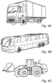
- the method 200 may be implemented in a vehicle, such as the truck, bus and construction equipment shown in Fig. 4 .
- the vehicles may be conventional or autonomous (driverless).
- the vehicles may carry the processor device 110 and sensors configured to collect data indicative of characteristics and parameters of the ESS.
- a terminal voltage of each battery pack 122 is obtained (e.g., by performing a measurement or receiving measurement data from an external source), and a respective time-evolved terminal voltage and current are predicted based thereon.
- the time-evolved terminal voltage/current may be represented as a sequence of voltage/current values associated with future points in time and may be predicted by a multi-battery system model.
- the current obtained from the multi-battery system model may be directly used as an input for step 212 wherein the chargeable/dischargeable capacity of the ESS 120 is computed, and the time-evolved terminal voltage may be further evaluated to obtain the expected charge/discharge time for each battery pack.
- the current for each battery pack 122 may be a predicted charge and/or discharge current for a battery pack, and may be determined by current split prediction from a multi-battery system model.
- the simplest case of current split prediction imposes the constraint of the sum of all currents being equal to the total reference ESS current (Kirchhoffs current law and Kirchhoffs voltage law), wherein the total reference ESS current may be based on manufacturer specified charging current profile, offline "charge capacity” testing and characterization, or historical charging history on ESS level logged by the processor device 110. Further input parameters such as impedances, resistances, capacities, voltages, and temperature may be taken into account for the current-split prediction.
- the current for each battery pack 122 may be a time-dependent function or a constant and may be different based on whether the battery is charging or discharging.
- a multi-battery system model may be configured to predict the time taken by each battery pack 122 to reach steady-state voltage value at the end of a charge and/or discharge cycle between different electrical energy storage packs in the ESS 120.
- a large number of useful multi-battery system models have been described in the literature.
- the multi-battery system model may approximate a single battery pack 122 as a circuit consisting of a resistor and a capacitor pair connected in parallel. To model the full multi-battery ESS 120, several such pairs are connected in series and in parallel.
- a multi-battery system model may use, in addition to the measured voltage, further input parameters such as battery temperature and/or a setpoint charge/discharge-current profile, but may use other input parameters such as open circuit voltage, impedances, capacities, cable connection resistance, temperature, SoC, state of current (SoQ), and/or state of resistance (SoR) for each battery unit, and/or a total flow current for the ESS 120.
- the multi-battery system model may be mathematically represented in the form of differential equations or in state-space form.
- any examples of the multi-battery system model as disclosed by the applicant in PCT/EP2019/086833 , PCT/EP2019/086835 , PCT/EP2020/066874 , PCT/EP2020/066919 , and PCT/EP2022/182283 , herein incorporated by reference, may be used to predict the time-evolved terminal voltages and/or currents for each battery pack.
- each battery pack i has a chargeable capacity Q c,i representing the current flow during the time it takes to reach a fully charged state from its current SoC level, and a dischargeable capacity Q d,i representing the current flow during the time it takes to reach an empty state from its current SoC level.
- T c ref and T d ref represent the minimum charge time and minimum discharge times from current SoC level
- t is the time at which the measured terminal voltage is obtained
- I ⁇ c , i ref and I ⁇ d , i ref are the predicted charge and discharge currents for an i th battery pack 122.
- the predicted charge and discharge currents can be determined by applying current split prediction to a predefined total charge and total discharge current trajectory I c , ESS ref , I d , ESS ref , respectively, using a multi-battery system model. It is understood that the above integrals are normally to be evaluated numerically.
- Computing the chargeable and/or dischargeable capacity of the ESS 120 may be based on other known methods, such as Kalman filter method, Luenberger observer method, proportional integral method, sliding mode method, or data-oriented methods such as using neural network, fuzzy logic or support vector machine model.
- the SoC of the ESS 120 is computed using the chargeable and/or dischargeable capacities of the ESS 120.
- the second step 212 includes a substep 212.1, where the expected charge/discharge time for each battery pack 122 is calculated.
- the predicted time-evolved terminal voltage obtained from the multi-battery system model provides an indication of the dynamical behaviour of each battery pack, and the expected charge/discharge time for each battery may thus be calculated by imposing boundary conditions on the time-evolved terminal voltage.
- an initial time may correspond to the time of measurement of the measured terminal voltage, and a final time may correspond to the time of reaching a charging/discharging limit voltage.
- the equality signs herein represent equality within approximation (e.g.,
- the charging limit voltage is the voltage level at which the battery pack 122 is considered fully charged/discharged and may be set individually to a nominally fully charged/discharged level or an extended fully charged/discharged level below or above the nominally fully charged/discharged level.
- the equilibrium condition corresponds to the level of saturation of charge in the battery pack 122 wherein the instantaneous rate of change for the time-evolved terminal voltage reaches, or approaches, zero.
- the charging/discharged limit voltage and equilibrium condition may be assumed, such as based on data obtained from a manufacturer or provider, based on measurements on the battery pack, calculated by the battery management system or obtained from a look-up table and may be set manually or automatically based on external or internal parameters such as vehicle performance requirements, route planning, driving data, lifetime, durability requirements, or battery cell parameters.
- Fig. 3 shows signal processing taking place in a processor device 110 that executes the method 200.
- the input parameters for predicting the time-evolved terminal voltage and current in a first step of using the multi-battery system model are the total ESS current I ESS ref , which may be total demanded input current, the state-of-charge for each battery pack SoC i , the state-of-capacity for each battery pack SoQ i , and the state-of-resistance for each battery pack SoR; , which may be estimated based on battery aging.
- the model may use further system parameters such as battery impedances, capacities, resistances, and/or temperatures.
- the model further uses a measured terminal voltage V i ( t ) for each battery pack 122 as input parameters, wherein the measurements may be done by sensors configured to send the measured input data to the processor device 110 via the interface 112.
- the model may use a measured current, temperature and/or SoC as input.
- the predicted time-evolved terminal voltage V ⁇ i and current Î i are obtained (the time dependences omitted for clarity).
- the time-evolved terminal voltage and current are time-evolved in the sense that they represent a sequence of voltage/current values along a predicted trajectory in a time-frame t + T , wherein t is the time of measurement of the measured terminal voltage, and T is a prediction time period in future.
- the time-evolved terminal voltage and current are predicted not only for a given instant in time, but also for a period of time adjacent to the given instant.
- the predicted time-evolved terminal voltage and current are then used to calculate the chargeable/dischargeable capacity as described in step 212 of Fig. 2 .
Landscapes
- General Physics & Mathematics (AREA)
- Physics & Mathematics (AREA)
- Engineering & Computer Science (AREA)
- Chemical Kinetics & Catalysis (AREA)
- Electrochemistry (AREA)
- General Chemical & Material Sciences (AREA)
- Chemical & Material Sciences (AREA)
- Life Sciences & Earth Sciences (AREA)
- Sustainable Development (AREA)
- Sustainable Energy (AREA)
- Power Engineering (AREA)
- Transportation (AREA)
- Mechanical Engineering (AREA)
- Aviation & Aerospace Engineering (AREA)
- Secondary Cells (AREA)
- Charge And Discharge Circuits For Batteries Or The Like (AREA)
Abstract
Description
- The disclosure is generally concerned with a multi-battery energy storage system (ESS) of parallel connected multi-battery units. In a particular aspect, the disclosure relates to a method of computing a state of charge of an energy storage system with multiple parallel battery packs.
- The disclosure relates to capacity and state of charge (SoC) estimations for an ESS with multiple parallel battery packs. From the viewpoint of a user or an autonomous-driving software operating a vehicle, an accurate computation of capacity and SoC is critical as it has impact on vehicle performance, drivability, range. Operating a vehicle based on incorrect capacity and SoC computations may lead to reduced performance (i.e., reduced power and electric range). In addition, unbalanced capacity and SoC may also consequently lead to increased wear on the battery and consequently increased maintenance requirements.
- In conventional approaches, estimating SoC and capacity for a larger system may be based on calculations on single-cell level. Although these calculations may be challenging per se, the complexity grows even further when estimating SoC and capacity of an ESS of parallel-connected battery units. Individual battery packs within a multi-battery ESS may exhibit non-homogeneous dynamic behaviours due to variations in internal and environmental parameters, which may include the battery packs having different charge levels, different ages, and/or being of different generations/types. Due to the complexity of these non-homogeneous dynamic behaviours, the problem of how to map individual battery states to a corresponding state of a multi-battery ESS has not yet been properly explored.
- Conventional methods include operating the ESS based on average state estimates and constraints dictated by the weakest battery pack in the network. However, these approaches are prone to errors and may lead to under-utilization or over-utilization of available ESS capacity. Consequently, improved systems and methods are needed to calculate capacity and SoC in a multi-battery ESS network exhibiting complex non-homogeneous dynamics such that the full ESS capability is utilized.
- According to a first aspect of the disclosure, there is provided a method of computing a state of charge of an energy storage system (ESS) with multiple parallel battery packs. The method comprises: for each battery pack, predicting a time-evolved terminal voltage and current based on a respective measured terminal voltage; based on the predicted time-evolved terminal voltages and currents, computing a chargeable and/or dischargeable capacity of the ESS; and computing the State-of-Charge of the ESS based on the chargeable and/or dischargeable capacity of the ESS.
- The first aspect of the disclosure may seek to provide an accurate computation of SoC for an ESS with multiple parallel battery packs such that the full capability (e.g., performance attribute such as useable energy and power ability, and long lifetime) of the ESS is utilized. The total capacity for the ESS is calculated by the sum of the chargeable and dischargeable capacity of the ESS, and the chargeable and dischargeable capacity of the ESS are based on the time evolution of the terminal voltage and current of each battery pack. The problem lies in that the time evolution of the terminal voltage and current of each battery pack is unknown and may be difficult to anticipate in the case of non-homogeneous battery packs. Calculating the SoC of the ESS based on estimates (in particular, based on a priori estimates) of the time-evolved terminal voltage and current, such as a pre-determined estimate given by a manufacturer, will result in an inaccurate estimate of available ESS capacity in an heterogeneous system. As an example, an estimated constraint dictated by the weakest battery pack will result in an under-estimation of the total available ESS capacity, especially since the estimated constrain may be set within safety marginals to account for any standard deviations. By instead calculating the ESS capacity based on a prediction of a time-evolved terminal voltage and current, a better understanding is provided of how the dynamics of each battery pack contributes to the total ESS capacity, which in turn generates a more accurate computation of chargeable capacity, dischargeable capacity and/or SoC for the ESS. Consequently, a prediction of a time-evolved terminal voltage and current solves the problem of providing an accurate computation of SoC for an ESS with multiple parallel battery packs such that the full capability of the ESS is utilized.
- In some embodiments, the chargeable capacity of the ESS is computed under an assumption of minimum charge time.
- In some embodiments, the minimum charge time is calculated by calculating an expected charge time for each battery pack based on its time-evolved terminal voltage and selecting, from the expected charge times for all battery packs, the smallest expected charge time as said minimum charge time. By these steps, a dynamical behavior for each battery pack is derived based on the prediction of the time-evolved terminal voltage, outlining the dynamics on a single pack-level. The expected charge time may be rephrased as the time taken by a battery pack to charge from the current SoC level and reach the full charging state limit (and also achieve an equilibrium, at which the terminal voltage is approximately constant) for a given charging current. The minimum charge time provides an appropriate time-frame wherein the chargeable capacity of the ESS is evaluated. In selecting the smallest expected charge time as said minimum charge time, the minimum charge time will be dictated by the battery pack in the ESS that charges in shortest time.
- In some embodiments, the dischargeable capacity of the ESS is computed under an assumption of minimum discharge time.
- In some embodiments, the minimum discharge time is calculated by calculating an expected discharge time for each battery pack based on its time-evolved terminal voltage and selecting, from the expected discharge times for all battery packs, the smallest expected discharge time as said minimum charge time. By these steps, a dynamical behavior for each battery pack is derived based on the prediction of the time-evolved terminal voltage, outlining the dynamics on a single pack-level. The expected discharge time may be rephrased as the time taken by a battery pack to discharge from the current SoC level and reach an empty discharging state limit (and thus achieve equilibrium) for a given discharging current. The minimum discharge time provides an appropriate time-frame wherein the dischargeable capacity of the ESS is evaluated. In selecting the smallest expected discharge time as said minimum discharge time, the minimum discharge time will be dictated by the battery pack in the ESS that drains in shortest time.
- In some embodiments, the time-evolved terminal voltages are predicted using a dynamic model of currents and voltages in a multi-battery system.
- In some embodiments, the current for each battery pack is predicted using current split prediction based on a total reference ESS current and a measured terminal voltage for each battery pack.
- Using the multi-battery system model allows for a smooth prediction for non-homogeneous battery packs leading to better predictions at any given time interval compared to prior art models, such as weakest link or average based models, which only converge towards accurate results at the end of maximum charge or discharge levels.
- According to a second aspect of the disclosure, there is provided a processor device for computing a state of charge of an energy storage system, ESS, with multiple parallel battery packs. The device comprises an interface for receiving sensor signals associated with the ESS and processing circuitry configured to perform the method of any of the preceding claims.
- According to a third aspect of the disclosure, there is provided a computer program product comprising program code for performing, when executed by the processor device, the method according to the first aspect of the invention.
- According to a fourth aspect of the disclosure, there is provided a non-transitory computer-readable storage medium comprising instructions which, when executed by the processor device, cause the processor device to perform the method according to the first aspect of the invention.
- The second, third and fourth aspects of this disclosure generally share the effects and advantages of the first aspect, as discussed above, and they can be implemented with a corresponding degree of technical variation.
- Generally, all terms used in the claims are to be interpreted according to their ordinary meaning in the technical field, unless explicitly defined otherwise herein. All references to "a/an/the element, apparatus, component, means, step, etc." are to be interpreted openly as referring to at least one instance of the element, apparatus, component, means, step, etc., unless explicitly stated otherwise. The steps of any method disclosed herein do not have to be performed in the exact order disclosed, unless explicitly stated.
- With reference to the appended drawings, below follows a more detailed description of aspects of the disclosure cited as examples. In the drawings:
-
Fig. 1 is a block diagram of a system according to example embodiments of the invention; -
Fig. 2 is a flowchart of method steps for computing a state of charge of an energy storage system, ESS, with multiple parallel battery packs; -
Fig. 3 is a block diagram showing signal processing during operation of the system shown inFig. 1 , according to example embodiments of the invention; and -
Fig. 4 shows example heavy commercial vehicles. - The present invention will now be described more fully hereinafter with reference to the accompanying drawings, in which exemplary embodiments of the invention are shown. The invention may, however, be embodied in many different forms and should not be construed as limited to the embodiments set forth herein; rather, these embodiments are provided for thoroughness and completeness. The skilled person will recognize that many changes and modifications may be made within the scope of the appended claims. Like reference characters refer to like elements throughout the description.
-
Fig. 1 conceptually illustrates a non-limiting example wherein the ESS 120 comprises two parallel connected battery packs 122-1, 122-2. However, it is understood that the ESS 120 may consist of any number of multiple battery packs 122, connected in parallel or in series. The present disclosure is mainly concerned with the case of parallel battery packs 122. A battery pack 122 may comprise at least one battery module, which in turn may comprise at least one battery cell. Thebattery packs 112 are configured to provide propulsion and/or power to a vehicle, but may be used in other fields such as for powering electrical devices, power tools, backup power systems, or power generation devices. -
Fig. 1 further shows aprocessor device 110 receiving input parameters from the ESS through aninterface 112, theprocessor device 110 having access to instructions for executing the method of the disclosure via thestorage medium 116. In particular, thestorage medium 116 may store acomputer program 118 comprising program code for performing the method of the disclosure. Theprocessor device 110 may, for example, include a general-purpose processor, an application specific processor, a Digital Signal Processor (DSP), an Application Specific Integrated Circuit (ASIC), a Field Programmable Gate Array (FPGA), a circuit containing processing components, a group of distributed processing components, a group of distributed computers configured for processing, or other programmable logic device, discrete gate or transistor logic, discrete hardware components, or any combination thereof designed to perform the functions described herein. Theprocessor device 110 may further include an external interface (not shown) allowing it to communicate with at least one analogously configured further device via a communication network (local-area network, wide-area network, intranet, extranet, Internet), and/or with a server or another host computer. Theprocessor device 110 may be used for data logging on-board regarding ESS usage. The logged data may be sent to a remote server (not shown) for further data analytics and insights. - The
interface 112 receives sensor signals associated with the ESS. The sensors are configured to collect data indicative of characteristics and parameters of the ESS, such as the measured terminal voltage. Such sensors may be voltage and/or current sensor for detecting a voltage of each battery pack 122, or an electrical discharge or charge current of each battery pack 122. The sensors may also include temperature sensors for measuring a temperature of each battery pack 122 or be configured to acquired drive pattern data that may indicate driver style or vehicle usage type. Because theESS 120 includes multiple battery packs 122, even though measurements are not necessarily performed on the levels below a battery pack (such as battery module, battery cell), there will be multiple measured voltages and/or currents available. The present disclosure proposes an efficient and precise approach for processing and utilizing this information to support a better understanding and usage of theESS 120, especially in an electric vehicle. Theinterface 112 outputs the collected sensor data indicative of characteristics and parameters of the ESS in a digital format. The output data may be accessed by theprocessing circuitry 114 andcomputer program 118 for causing the processor device to perform the method of the disclosure. -
Fig. 2 is a flowchart of amethod 200 for computing a state of charge of anESS 120 with multiple parallel battery packs 122, like the one that has been described with reference toFig. 1 . Themethod 200 can be implemented in aprocessor device 110 of the type also shown inFig. 1 , which has access to terminal voltage of each the battery packs 122 of theESS 120. The description of themethod 200, which now follows, can be understood with further reference toFig. 3 , which illustrates certain information flows and/or signal processing that may occur while themethod 200 is performed. Themethod 200 may be implemented in a vehicle, such as the truck, bus and construction equipment shown inFig. 4 . The vehicles may be conventional or autonomous (driverless). The vehicles may carry theprocessor device 110 and sensors configured to collect data indicative of characteristics and parameters of the ESS. - In a
first step 210 of themethod 200, a terminal voltage of each battery pack 122 is obtained (e.g., by performing a measurement or receiving measurement data from an external source), and a respective time-evolved terminal voltage and current are predicted based thereon. The time-evolved terminal voltage/current may be represented as a sequence of voltage/current values associated with future points in time and may be predicted by a multi-battery system model. The current obtained from the multi-battery system model may be directly used as an input forstep 212 wherein the chargeable/dischargeable capacity of theESS 120 is computed, and the time-evolved terminal voltage may be further evaluated to obtain the expected charge/discharge time for each battery pack. - The current for each battery pack 122 may be a predicted charge and/or discharge current for a battery pack, and may be determined by current split prediction from a multi-battery system model. The simplest case of current split prediction imposes the constraint of the sum of all currents being equal to the total reference ESS current (Kirchhoffs current law and Kirchhoffs voltage law), wherein the total reference ESS current may be based on manufacturer specified charging current profile, offline "charge capacity" testing and characterization, or historical charging history on ESS level logged by the
processor device 110. Further input parameters such as impedances, resistances, capacities, voltages, and temperature may be taken into account for the current-split prediction. The current for each battery pack 122 may be a time-dependent function or a constant and may be different based on whether the battery is charging or discharging. - A multi-battery system model may be configured to predict the time taken by each battery pack 122 to reach steady-state voltage value at the end of a charge and/or discharge cycle between different electrical energy storage packs in the
ESS 120. A large number of useful multi-battery system models have been described in the literature. For example, the multi-battery system model may approximate a single battery pack 122 as a circuit consisting of a resistor and a capacitor pair connected in parallel. To model thefull multi-battery ESS 120, several such pairs are connected in series and in parallel. In general, a multi-battery system model may use, in addition to the measured voltage, further input parameters such as battery temperature and/or a setpoint charge/discharge-current profile, but may use other input parameters such as open circuit voltage, impedances, capacities, cable connection resistance, temperature, SoC, state of current (SoQ), and/or state of resistance (SoR) for each battery unit, and/or a total flow current for theESS 120. The multi-battery system model may be mathematically represented in the form of differential equations or in state-space form. Any examples of the multi-battery system model as disclosed by the applicant inPCT/EP2019/086833 PCT/EP2019/086835 PCT/EP2020/066874 PCT/EP2020/066919 PCT/EP2022/182283 - Predicting the time-evolved terminal voltages and current for each battery pack 122 may further be based on other types of models or even look-up tables. The multi-battery model may take into account the effect of temperature variations, and may also include a simple thermal model to predict the temperature evaluation during various operating conditions.
- In
second step 212 in themethod 200, the chargeable/dischargeable capacity of theESS 120 is being computed using a Coulomb-counting approach, wherein the battery current during charge and discharge is temporally integrated. On a single pack level, each battery pack i has a chargeable capacity Qc,i representing the current flow during the time it takes to reach a fully charged state from its current SoC level, and a dischargeable capacity Qd,i representing the current flow during the time it takes to reach an empty state from its current SoC level. The dischargeable and chargeable capacities computed by the Coulomb counting approach may be expressed as


- Computing the chargeable and/or dischargeable capacity of the
ESS 120 may be based on other known methods, such as Kalman filter method, Luenberger observer method, proportional integral method, sliding mode method, or data-oriented methods such as using neural network, fuzzy logic or support vector machine model. - In a
third step 214 in themethod 200 shown inFig. 2 , the SoC of theESS 120 is computed using the chargeable and/or dischargeable capacities of theESS 120. The total capacity for one battery pack 122 will then be expressed as the sum of chargeable and dischargeable capacities,
ESS 120 is given by
Fig. 1 . The SoC of thetotal ESS 120 may then be computed using any two of either the total capacity, the chargeable capacity, or the dischargeable capacity as given by the relationship
- Optionally, in some embodiments, the
second step 212 includes a substep 212.1, where the expected charge/discharge time for each battery pack 122 is calculated. The predicted time-evolved terminal voltage obtained from the multi-battery system model provides an indication of the dynamical behaviour of each battery pack, and the expected charge/discharge time for each battery may thus be calculated by imposing boundary conditions on the time-evolved terminal voltage. - For each battery pack, an initial time may correspond to the time of measurement of the measured terminal voltage, and a final time may correspond to the time of reaching a charging/discharging limit voltage. The expected charge/discharge time for each battery pack 122 is then given by minimizing the time-frame between the initial time and final time, and may in an exemplary embodiment be expressed as


- The charging limit voltage is the voltage level at which the battery pack 122 is considered fully charged/discharged and may be set individually to a nominally fully charged/discharged level or an extended fully charged/discharged level below or above the nominally fully charged/discharged level. The equilibrium condition corresponds to the level of saturation of charge in the battery pack 122 wherein the instantaneous rate of change for the time-evolved terminal voltage reaches, or approaches, zero. The charging/discharged limit voltage and equilibrium condition may be assumed, such as based on data obtained from a manufacturer or provider, based on measurements on the battery pack, calculated by the battery management system or obtained from a look-up table and may be set manually or automatically based on external or internal parameters such as vehicle performance requirements, route planning, driving data, lifetime, durability requirements, or battery cell parameters.
- In some embodiments, the
method 200 further comprises a substep 212.2, in which the minimum charge/discharge time are calculated by selecting the smallest expected charge time from the expected charge times for all battery packs 122, that is,


ESS 120 and are dictated by the battery pack 122 inESS 120 that drains/fills at fastest rate. -
Fig. 3 shows signal processing taking place in aprocessor device 110 that executes themethod 200. The notation is consistent with one used in the foregoing description. The input parameters for predicting the time-evolved terminal voltage and current in a first step of using the multi-battery system model are the total ESS current
processor device 110 via theinterface 112. Optionally, the model may use a measured current, temperature and/or SoC as input. - From the multi-battery system model, the predicted time-evolved terminal voltage V̂i and current Îi are obtained (the time dependences omitted for clarity). The time-evolved terminal voltage and current are time-evolved in the sense that they represent a sequence of voltage/current values along a predicted trajectory in a time-frame t + T, wherein t is the time of measurement of the measured terminal voltage, and T is a prediction time period in future. In other words, the time-evolved terminal voltage and current are predicted not only for a given instant in time, but also for a period of time adjacent to the given instant. The predicted time-evolved terminal voltage and current are then used to calculate the chargeable/dischargeable capacity as described in
step 212 ofFig. 2 . - The aspects of the present disclosure have mainly been described above with reference to a few embodiments. However, as is readily appreciated by a person skilled in the art, other embodiments than the ones disclosed above are equally possible within the scope of the invention, as defined by the appended patent claims.
Claims (15)
- A method (200) of computing a state of charge of an energy storage system, ESS (120), with multiple parallel battery packs, the method comprising:for each battery pack, predicting (210) a time-evolved terminal voltage and current based on a respective measured terminal voltage;based on the predicted time-evolved terminal voltages and currents, computing (212) a chargeable and/or dischargeable capacity of the ESS; andcomputing (214) the state of charge of the ESS based on the chargeable and/or dischargeable capacity of the ESS.
- The method of claim 1, wherein the chargeable and/or dischargeable capacity of the ESS is computed (212) using a Coulomb-counting approach.
- The method of any of the preceding claims, wherein the chargeable capacity of the ESS is computed (212) under an assumption of minimum charge time.
- The method of claim 3, wherein the minimum charge time is calculated by:calculating (212.1) an expected charge time for each battery pack based on its time-evolved terminal voltage; andselecting (212.2), from the expected charge times for all battery packs, the smallest expected charge time as said minimum charge time.
- The method of claim 4, wherein the expected charge time is calculated by applying to the time-evolved terminal voltage a termination criterion including a charging limit voltage and an equilibrium condition.
- The method of any of the preceding claims, wherein the dischargeable capacity of the ESS is computed (212) under an assumption of minimum discharge time.
- The method of claim 6, wherein the minimum discharge time is calculated by:calculating (212.1) an expected discharge time for each battery pack based on its time-evolved terminal voltage; andselecting, (212.2) from the expected discharge times for all battery packs, the smallest expected discharge time as said minimum charge time.
- The method of claim 7, wherein the expected discharge time is calculated by applying to the time-evolved terminal voltage a termination criterion including a discharging limit voltage and an equilibrium condition.
- The method of any of the preceding claims, wherein the time-evolved terminal voltages are predicted (110) using a dynamic model of currents and voltages in a multi-battery system.
- The method of claim 9, wherein the model is variable with respect to battery temperature and/or a setpoint charge/discharge-current profile.
- The method of any of the preceding claims, wherein the current for each battery pack is predicted (210) using current split prediction based on a total reference ESS current and a measured terminal voltage for the battery pack.
- The method of any of the preceding claims, wherein the ESS is a vehicular ESS.
- A processor device (110) for computing a state of charge of an energy storage system, ESS, (120) with multiple parallel battery packs (122-1, 122-2), the device comprising:an interface (112) for receiving sensor signals associated with the ESS; andprocessing circuitry (114) configured to perform the method of any of the preceding claims.
- A computer program product (118) comprising program code for performing, when executed by the processor device (110) of claim 13, the method of any of claims 1 to 12.
- A non-transitory computer-readable storage medium (116) comprising instructions which, when executed by the processor device (110) of claim 13, cause the processor device to perform the method of any of claims 1 to 12.
Priority Applications (3)
| Application Number | Priority Date | Filing Date | Title |
|---|---|---|---|
| EP22214914.8A EP4390416B1 (en) | 2022-12-20 | 2022-12-20 | Capacity and state-of-charge estimation for a multi-battery energy storage system |
| US18/541,220 US20240201269A1 (en) | 2022-12-20 | 2023-12-15 | Capacity and state-of-charge estimation for a multi-battery energy storage system |
| CN202311732885.XA CN118226289A (en) | 2022-12-20 | 2023-12-15 | Capacity and state of charge estimation for multi-battery energy storage systems |
Applications Claiming Priority (1)
| Application Number | Priority Date | Filing Date | Title |
|---|---|---|---|
| EP22214914.8A EP4390416B1 (en) | 2022-12-20 | 2022-12-20 | Capacity and state-of-charge estimation for a multi-battery energy storage system |
Publications (2)
| Publication Number | Publication Date |
|---|---|
| EP4390416A1 true EP4390416A1 (en) | 2024-06-26 |
| EP4390416B1 EP4390416B1 (en) | 2025-10-29 |
Family
ID=84541598
Family Applications (1)
| Application Number | Title | Priority Date | Filing Date |
|---|---|---|---|
| EP22214914.8A Active EP4390416B1 (en) | 2022-12-20 | 2022-12-20 | Capacity and state-of-charge estimation for a multi-battery energy storage system |
Country Status (3)
| Country | Link |
|---|---|
| US (1) | US20240201269A1 (en) |
| EP (1) | EP4390416B1 (en) |
| CN (1) | CN118226289A (en) |
Citations (3)
| Publication number | Priority date | Publication date | Assignee | Title |
|---|---|---|---|---|
| US20120119749A1 (en) * | 2010-03-26 | 2012-05-17 | Takuma Iida | Charge state detection circuit, battery power supply device, and battery information monitoring device |
| US20130271068A1 (en) * | 2010-12-16 | 2013-10-17 | Honda Motor Co., Ltd. | Battery control apparatus and battery control method |
| US20210288353A1 (en) * | 2020-03-10 | 2021-09-16 | Samsung Electronics Co., Ltd. | Methods and electronic devices for obtaining information on a battery pack |
-
2022
- 2022-12-20 EP EP22214914.8A patent/EP4390416B1/en active Active
-
2023
- 2023-12-15 CN CN202311732885.XA patent/CN118226289A/en active Pending
- 2023-12-15 US US18/541,220 patent/US20240201269A1/en active Pending
Patent Citations (3)
| Publication number | Priority date | Publication date | Assignee | Title |
|---|---|---|---|---|
| US20120119749A1 (en) * | 2010-03-26 | 2012-05-17 | Takuma Iida | Charge state detection circuit, battery power supply device, and battery information monitoring device |
| US20130271068A1 (en) * | 2010-12-16 | 2013-10-17 | Honda Motor Co., Ltd. | Battery control apparatus and battery control method |
| US20210288353A1 (en) * | 2020-03-10 | 2021-09-16 | Samsung Electronics Co., Ltd. | Methods and electronic devices for obtaining information on a battery pack |
Non-Patent Citations (1)
| Title |
|---|
| DONG GUANGZHONG ET AL: "Determination of the load capability for a lithium-ion battery pack using two time-scale filtering", JOURNAL OF POWER SOURCES, ELSEVIER, AMSTERDAM, NL, vol. 480, 15 October 2020 (2020-10-15), XP086351099, ISSN: 0378-7753, [retrieved on 20201015], DOI: 10.1016/J.JPOWSOUR.2020.229056 * |
Also Published As
| Publication number | Publication date |
|---|---|
| CN118226289A (en) | 2024-06-21 |
| EP4390416B1 (en) | 2025-10-29 |
| US20240201269A1 (en) | 2024-06-20 |
Similar Documents
| Publication | Publication Date | Title |
|---|---|---|
| JP6848144B2 (en) | A device for estimating the charge state of a secondary battery and its method | |
| EP1873542B1 (en) | Apparatus and method for estimating charge of a battery | |
| US10955479B2 (en) | Battery control device | |
| US12252021B2 (en) | Method for estimating an operating parameter of a battery unit | |
| CN114585936B (en) | Method and apparatus for determining state of charge and state of health of a rechargeable battery | |
| US11342596B2 (en) | Method and system for controlling a rechargeable battery | |
| JP4767558B2 (en) | Power supply state detection device, power supply device, and initial characteristic extraction device used for power supply device | |
| US9205755B2 (en) | Receding horizon regression analysis for battery impedance parameter estimation | |
| US10048319B2 (en) | Estimating of the state of charge of a battery | |
| US20160274193A1 (en) | Battery remaining power predicting device and battery pack | |
| EP3832331A1 (en) | Cell state estimation device and cell control device | |
| KR20060107535A (en) | How to calculate the power capacity of a battery pack using advanced cell model prediction technology | |
| JP6450565B2 (en) | Battery parameter estimation device | |
| WO2018162023A2 (en) | A battery state of power estimation method and a battery state monitoring system | |
| KR20160110221A (en) | Remaining battery life prediction device and battery pack | |
| CN113826019A (en) | Method for estimating battery state | |
| Kessels et al. | On-line battery identification for electric driving range prediction | |
| Fotouhi et al. | State of charge and state of health estimation over the battery lifespan | |
| US11953558B2 (en) | Method and system for estimating the state-of-health of a battery | |
| Mitra et al. | Model-based estimation of state of charge and state of power of a lithium ion battery pack and their effects on energy management in hybrid electric vehicles: D. Mitra et al. | |
| CN116256658A (en) | Method and apparatus for providing device battery pack aging status using corrections to status observations based on systemic status and environmental influences | |
| EP4390416B1 (en) | Capacity and state-of-charge estimation for a multi-battery energy storage system | |
| Padalale et al. | State of charge (soc) determination through extended kalman filter in battery management systems | |
| JP6485439B2 (en) | Power storage system | |
| WO2025173451A1 (en) | Estimation method, estimation apparatus, and computer program |
Legal Events
| Date | Code | Title | Description |
|---|---|---|---|
| PUAI | Public reference made under article 153(3) epc to a published international application that has entered the european phase |
Free format text: ORIGINAL CODE: 0009012 |
|
| STAA | Information on the status of an ep patent application or granted ep patent |
Free format text: STATUS: REQUEST FOR EXAMINATION WAS MADE |
|
| 17P | Request for examination filed |
Effective date: 20231214 |
|
| AK | Designated contracting states |
Kind code of ref document: A1 Designated state(s): AL AT BE BG CH CY CZ DE DK EE ES FI FR GB GR HR HU IE IS IT LI LT LU LV MC ME MK MT NL NO PL PT RO RS SE SI SK SM TR |
|
| RIC1 | Information provided on ipc code assigned before grant |
Ipc: G01R 31/3842 20190101ALN20250305BHEP Ipc: G01R 31/3828 20190101ALN20250305BHEP Ipc: B60L 3/12 20060101ALI20250305BHEP Ipc: B60L 58/18 20190101ALI20250305BHEP Ipc: G01R 31/3835 20190101ALI20250305BHEP Ipc: G01R 31/396 20190101ALI20250305BHEP Ipc: G01R 31/367 20190101AFI20250305BHEP |
|
| GRAP | Despatch of communication of intention to grant a patent |
Free format text: ORIGINAL CODE: EPIDOSNIGR1 |
|
| STAA | Information on the status of an ep patent application or granted ep patent |
Free format text: STATUS: GRANT OF PATENT IS INTENDED |
|
| RIC1 | Information provided on ipc code assigned before grant |
Ipc: G01R 31/3842 20190101ALN20250415BHEP Ipc: G01R 31/3828 20190101ALN20250415BHEP Ipc: B60L 3/12 20060101ALI20250415BHEP Ipc: B60L 58/18 20190101ALI20250415BHEP Ipc: G01R 31/3835 20190101ALI20250415BHEP Ipc: G01R 31/396 20190101ALI20250415BHEP Ipc: G01R 31/367 20190101AFI20250415BHEP |
|
| INTG | Intention to grant announced |
Effective date: 20250508 |
|
| GRAS | Grant fee paid |
Free format text: ORIGINAL CODE: EPIDOSNIGR3 |
|
| GRAA | (expected) grant |
Free format text: ORIGINAL CODE: 0009210 |
|
| STAA | Information on the status of an ep patent application or granted ep patent |
Free format text: STATUS: THE PATENT HAS BEEN GRANTED |
|
| AK | Designated contracting states |
Kind code of ref document: B1 Designated state(s): AL AT BE BG CH CY CZ DE DK EE ES FI FR GB GR HR HU IE IS IT LI LT LU LV MC ME MK MT NL NO PL PT RO RS SE SI SK SM TR |
|
| REG | Reference to a national code |
Ref country code: CH Ref legal event code: F10 Free format text: ST27 STATUS EVENT CODE: U-0-0-F10-F00 (AS PROVIDED BY THE NATIONAL OFFICE) Effective date: 20251029 Ref country code: GB Ref legal event code: FG4D |
|
| REG | Reference to a national code |
Ref country code: IE Ref legal event code: FG4D |
|
| REG | Reference to a national code |
Ref country code: DE Ref legal event code: R096 Ref document number: 602022023883 Country of ref document: DE |
|
| PGFP | Annual fee paid to national office [announced via postgrant information from national office to epo] |
Ref country code: AT Payment date: 20260113 Year of fee payment: 4 |
|
| REG | Reference to a national code |
Ref country code: NL Ref legal event code: MP Effective date: 20251029 |
|
| PG25 | Lapsed in a contracting state [announced via postgrant information from national office to epo] |
Ref country code: ES Free format text: LAPSE BECAUSE OF FAILURE TO SUBMIT A TRANSLATION OF THE DESCRIPTION OR TO PAY THE FEE WITHIN THE PRESCRIBED TIME-LIMIT Effective date: 20251029 |
|
| REG | Reference to a national code |
Ref country code: LT Ref legal event code: MG9D |
|
| PG25 | Lapsed in a contracting state [announced via postgrant information from national office to epo] |
Ref country code: NO Free format text: LAPSE BECAUSE OF FAILURE TO SUBMIT A TRANSLATION OF THE DESCRIPTION OR TO PAY THE FEE WITHIN THE PRESCRIBED TIME-LIMIT Effective date: 20260129 |
|
| PGFP | Annual fee paid to national office [announced via postgrant information from national office to epo] |
Ref country code: DE Payment date: 20251222 Year of fee payment: 4 |
|
| PG25 | Lapsed in a contracting state [announced via postgrant information from national office to epo] |
Ref country code: HR Free format text: LAPSE BECAUSE OF FAILURE TO SUBMIT A TRANSLATION OF THE DESCRIPTION OR TO PAY THE FEE WITHIN THE PRESCRIBED TIME-LIMIT Effective date: 20251029 Ref country code: AT Free format text: LAPSE BECAUSE OF FAILURE TO SUBMIT A TRANSLATION OF THE DESCRIPTION OR TO PAY THE FEE WITHIN THE PRESCRIBED TIME-LIMIT Effective date: 20251029 Ref country code: FI Free format text: LAPSE BECAUSE OF FAILURE TO SUBMIT A TRANSLATION OF THE DESCRIPTION OR TO PAY THE FEE WITHIN THE PRESCRIBED TIME-LIMIT Effective date: 20251029 |
|
| REG | Reference to a national code |
Ref country code: AT Ref legal event code: MK05 Ref document number: 1852118 Country of ref document: AT Kind code of ref document: T Effective date: 20251029 |
|
| PG25 | Lapsed in a contracting state [announced via postgrant information from national office to epo] |
Ref country code: NL Free format text: LAPSE BECAUSE OF FAILURE TO SUBMIT A TRANSLATION OF THE DESCRIPTION OR TO PAY THE FEE WITHIN THE PRESCRIBED TIME-LIMIT Effective date: 20251029 |
|
| PG25 | Lapsed in a contracting state [announced via postgrant information from national office to epo] |
Ref country code: RS Free format text: LAPSE BECAUSE OF FAILURE TO SUBMIT A TRANSLATION OF THE DESCRIPTION OR TO PAY THE FEE WITHIN THE PRESCRIBED TIME-LIMIT Effective date: 20260129 |
|
| PG25 | Lapsed in a contracting state [announced via postgrant information from national office to epo] |
Ref country code: IS Free format text: LAPSE BECAUSE OF FAILURE TO SUBMIT A TRANSLATION OF THE DESCRIPTION OR TO PAY THE FEE WITHIN THE PRESCRIBED TIME-LIMIT Effective date: 20260228 |
|
| PG25 | Lapsed in a contracting state [announced via postgrant information from national office to epo] |
Ref country code: PT Free format text: LAPSE BECAUSE OF FAILURE TO SUBMIT A TRANSLATION OF THE DESCRIPTION OR TO PAY THE FEE WITHIN THE PRESCRIBED TIME-LIMIT Effective date: 20260302 |
|
| PG25 | Lapsed in a contracting state [announced via postgrant information from national office to epo] |
Ref country code: PL Free format text: LAPSE BECAUSE OF FAILURE TO SUBMIT A TRANSLATION OF THE DESCRIPTION OR TO PAY THE FEE WITHIN THE PRESCRIBED TIME-LIMIT Effective date: 20251029 |
|
| PG25 | Lapsed in a contracting state [announced via postgrant information from national office to epo] |
Ref country code: LV Free format text: LAPSE BECAUSE OF FAILURE TO SUBMIT A TRANSLATION OF THE DESCRIPTION OR TO PAY THE FEE WITHIN THE PRESCRIBED TIME-LIMIT Effective date: 20251029 |
|
| PG25 | Lapsed in a contracting state [announced via postgrant information from national office to epo] |
Ref country code: BG Free format text: LAPSE BECAUSE OF FAILURE TO SUBMIT A TRANSLATION OF THE DESCRIPTION OR TO PAY THE FEE WITHIN THE PRESCRIBED TIME-LIMIT Effective date: 20251029 |