EP4390389A2 - Hybrid gradient delivery system and operation - Google Patents
Hybrid gradient delivery system and operation Download PDFInfo
- Publication number
- EP4390389A2 EP4390389A2 EP24167185.8A EP24167185A EP4390389A2 EP 4390389 A2 EP4390389 A2 EP 4390389A2 EP 24167185 A EP24167185 A EP 24167185A EP 4390389 A2 EP4390389 A2 EP 4390389A2
- Authority
- EP
- European Patent Office
- Prior art keywords
- solvent
- stream
- gradient
- low
- pressure gradient
- Prior art date
- Legal status (The legal status is an assumption and is not a legal conclusion. Google has not performed a legal analysis and makes no representation as to the accuracy of the status listed.)
- Pending
Links
Images


Classifications
-
- B—PERFORMING OPERATIONS; TRANSPORTING
- B01—PHYSICAL OR CHEMICAL PROCESSES OR APPARATUS IN GENERAL
- B01D—SEPARATION
- B01D15/00—Separating processes involving the treatment of liquids with solid sorbents; Apparatus therefor
- B01D15/08—Selective adsorption, e.g. chromatography
- B01D15/10—Selective adsorption, e.g. chromatography characterised by constructional or operational features
- B01D15/14—Selective adsorption, e.g. chromatography characterised by constructional or operational features relating to the introduction of the feed to the apparatus
-
- B—PERFORMING OPERATIONS; TRANSPORTING
- B01—PHYSICAL OR CHEMICAL PROCESSES OR APPARATUS IN GENERAL
- B01D—SEPARATION
- B01D15/00—Separating processes involving the treatment of liquids with solid sorbents; Apparatus therefor
- B01D15/08—Selective adsorption, e.g. chromatography
- B01D15/10—Selective adsorption, e.g. chromatography characterised by constructional or operational features
- B01D15/16—Selective adsorption, e.g. chromatography characterised by constructional or operational features relating to the conditioning of the fluid carrier
- B01D15/166—Fluid composition conditioning, e.g. gradient
-
- G—PHYSICS
- G01—MEASURING; TESTING
- G01N—INVESTIGATING OR ANALYSING MATERIALS BY DETERMINING THEIR CHEMICAL OR PHYSICAL PROPERTIES
- G01N30/00—Investigating or analysing materials by separation into components using adsorption, absorption or similar phenomena or using ion-exchange, e.g. chromatography or field flow fractionation
- G01N30/02—Column chromatography
- G01N30/26—Conditioning of the fluid carrier; Flow patterns
- G01N30/28—Control of physical parameters of the fluid carrier
- G01N30/34—Control of physical parameters of the fluid carrier of fluid composition, e.g. gradient
-
- G—PHYSICS
- G01—MEASURING; TESTING
- G01N—INVESTIGATING OR ANALYSING MATERIALS BY DETERMINING THEIR CHEMICAL OR PHYSICAL PROPERTIES
- G01N30/00—Investigating or analysing materials by separation into components using adsorption, absorption or similar phenomena or using ion-exchange, e.g. chromatography or field flow fractionation
- G01N30/02—Column chromatography
- G01N30/04—Preparation or injection of sample to be analysed
- G01N30/16—Injection
- G01N30/20—Injection using a sampling valve
-
- G—PHYSICS
- G01—MEASURING; TESTING
- G01N—INVESTIGATING OR ANALYSING MATERIALS BY DETERMINING THEIR CHEMICAL OR PHYSICAL PROPERTIES
- G01N30/00—Investigating or analysing materials by separation into components using adsorption, absorption or similar phenomena or using ion-exchange, e.g. chromatography or field flow fractionation
- G01N30/02—Column chromatography
- G01N30/26—Conditioning of the fluid carrier; Flow patterns
- G01N30/28—Control of physical parameters of the fluid carrier
- G01N30/32—Control of physical parameters of the fluid carrier of pressure or speed
-
- G—PHYSICS
- G01—MEASURING; TESTING
- G01N—INVESTIGATING OR ANALYSING MATERIALS BY DETERMINING THEIR CHEMICAL OR PHYSICAL PROPERTIES
- G01N30/00—Investigating or analysing materials by separation into components using adsorption, absorption or similar phenomena or using ion-exchange, e.g. chromatography or field flow fractionation
- G01N30/02—Column chromatography
- G01N30/26—Conditioning of the fluid carrier; Flow patterns
- G01N30/38—Flow patterns
-
- Y—GENERAL TAGGING OF NEW TECHNOLOGICAL DEVELOPMENTS; GENERAL TAGGING OF CROSS-SECTIONAL TECHNOLOGIES SPANNING OVER SEVERAL SECTIONS OF THE IPC; TECHNICAL SUBJECTS COVERED BY FORMER USPC CROSS-REFERENCE ART COLLECTIONS [XRACs] AND DIGESTS
- Y10—TECHNICAL SUBJECTS COVERED BY FORMER USPC
- Y10T—TECHNICAL SUBJECTS COVERED BY FORMER US CLASSIFICATION
- Y10T137/00—Fluid handling
- Y10T137/0318—Processes
- Y10T137/0324—With control of flow by a condition or characteristic of a fluid
- Y10T137/0363—For producing proportionate flow
-
- Y—GENERAL TAGGING OF NEW TECHNOLOGICAL DEVELOPMENTS; GENERAL TAGGING OF CROSS-SECTIONAL TECHNOLOGIES SPANNING OVER SEVERAL SECTIONS OF THE IPC; TECHNICAL SUBJECTS COVERED BY FORMER USPC CROSS-REFERENCE ART COLLECTIONS [XRACs] AND DIGESTS
- Y10—TECHNICAL SUBJECTS COVERED BY FORMER USPC
- Y10T—TECHNICAL SUBJECTS COVERED BY FORMER US CLASSIFICATION
- Y10T137/00—Fluid handling
- Y10T137/8593—Systems
- Y10T137/85978—With pump
- Y10T137/85986—Pumped fluid control
Definitions
- the invention relates generally to liquid chromatography systems. More specifically, the invention relates to hybrid gradient delivery systems that combine aspects of high-pressure gradient systems and low-pressure gradient systems.
- Chromatography is a set of techniques for separating a mixture into its constituents.
- one or more high-pressure pumps take in solvents and deliver a liquid solvent composition to a sample manager, where a sample awaits injection into the mixture.
- the sample is the material under analysis, examples of which include complex mixtures of proteins, protein precursors, protein fragments, reaction products, and other compounds, to list but a few.
- the resulting liquid composition comprised of the mixture of solvents and injected sample, moves to a point of use, such as a column of particulate matter.
- a detector receives the elution from the column and produces an output from which the identity and quantity of the analytes may be determined.
- High-performance liquid chromatography uses two basic elution modes: isocratic elution and gradient elution.
- the mobile phase comprised of either a pure solvent or a mixture of solvents
- the gradient elution mode the composition of the mobile phase changes during the separation.
- Creation of the gradient entails the mixing of multiple solvents, the proportions of which change over time in accordance with a predetermined timetable.
- Some HPLC systems create the gradient under high pressure, by mixing the solvents downstream of the pumps. Such HPLC systems are also referred to herein as high-pressure gradient systems.
- HPLC systems create the gradient under low pressure, using a gradient proportioning valve to select from up to four solvents, mixing the multiple solvents in front of a single aspirating pump, and changing the proportions of the solvents over time.
- Such HPLC systems are also referred to herein as low-pressure gradient systems.
- high-pressure gradient systems have lesser dwell volumes than low-pressure gradient systems because the solvent mixing occurs after the pumps instead of before the intake side of the pump.
- low-pressure gradient systems can produce a gradient with just one pump, whereas high-pressure gradient systems generally require one pump for each solvent.
- low-pressure gradient systems are more amenable than high-pressure gradient systems to tertiary and quaternary gradients, and are thus predominantly used for such chromatography applications, whereas high-pressure gradient systems are generally used for binary gradients.
- a third solvent being a modifier, such as TFA (triflouroacetic acid), introduced at a constant percentage.
- TFA triflouroacetic acid
- TFA triflouroacetic acid
- a low-pressure gradient system is generally used for chromatography runs to introduce the third modifier solvent instead of a high-pressure gradient system.
- Use of the low-pressure gradient system for this purpose has disadvantages of an increased dwell volume (in comparison to a high-pressure gradient system) and limiting the maximum percentage of one of the two other solvents to 90%.
- the invention features a solvent delivery system for use in a liquid chromatography system.
- the solvent delivery system comprises a gradient proportioning valve in fluidic communication with a plurality of sources of solvent and producing therefrom a low-pressure gradient stream.
- a first pump is in fluidic communication with the gradient proportioning valve to receive and pressurize the low-pressure gradient stream and to move the pressurized low-pressure gradient stream to a flow-combining device.
- a second pump operates in parallel with the first pump. The second pump moves a pressurized solvent stream to the flow-combining device where the pressurized solvent stream combines with the pressurized low-pressure gradient stream to produce a high-pressure gradient stream.
- the invention features a method for blending solvents in a liquid chromatography system.
- a low-pressure gradient stream is produced from a plurality of sources of solvent, pressurized, and moved to a flow-combining device while a pressurized solvent stream is moved to the flow-combining device.
- the pressurized solvent stream mixes with the pressurized low-pressure gradient stream to produce a high-pressure gradient stream.
- the invention features a liquid chromatography system comprising a solvent delivery system.
- the solvent delivery system includes a gradient proportioning valve in fluidic communication with a plurality of sources of solvent, producing therefrom a low-pressure gradient stream.
- a first pump is in fluidic communication with the gradient proportioning valve to receive and pressurize the low-pressure gradient stream and to move the pressurized low-pressure gradient stream to a flow-combining device.
- a second pump operates in parallel with the first pump. The second pump moves a pressurized solvent stream to the flow-combining device where the pressurized solvent stream combines with the pressurized low-pressure gradient stream to produce a high-pressure gradient stream.
- Solvent delivery systems described herein can be deemed hybrid systems because they combine features of a high-pressure gradient system with those of a low-pressure gradient system. As a hybrid, the solvent delivery systems function primarily as binary gradient systems having minimized dwell volume and flexibility for solvent selection.
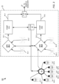
- FIG. 1 shows an embodiment of a hybrid solvent delivery system 10 for producing and moving a solvent composition to a sample manager (not shown), also known as an autosampler, where a sample is introduced to the solvent composition.
- the features of a high-pressure gradient system adapted for use by the hybrid solvent delivery system 10, outlined by dashed box 16, include two pumps 14-1, 14-2 (generally, 14) operating in parallel.
- each pump 14-1, 14-2 includes a primary pumping actuator and an accumulator pumping actuator coupled in series.
- the pumps 14 can be of the type used in the 2545 Binary Gradient Module manufactured by Waters Corporation of Milford, MA.
- the outlets of the pump 14-1, 14-2 are connected at the same or substantially the same mechanical location, here represented as a flow-combining device (FCD) 20.
- FCD flow-combining device
- Example implementations of the flow-combining device 20 include, but are not limited to, a T-section and a mixer.
- Each pump 14-1, 14-2 moves a solvent stream 18-1, 18-2, respectively, at high pressure, to this flow-combining device 20, where the pressurized solvent streams 18-1, 18-2 combine to produce a pressurized solvent composition 22 that is delivered over time to the sample manager.
- a gradient controller 24 is in communication with the pumps 14 to manage the speed of each pump 14 in order to deliver more or less of each solvent stream 18-1, 18-2 over the course of the separation.
- each GPV 28 is in fluidic communication with up to four solvent reservoirs 30 (here, only two reservoirs per GPV are shown; the GPV 28-1 is in fluidic communication with solvent reservoirs 30-1, 30-2; and the GPV 28-2 is in fluidic communication with solvent reservoirs 30-3, 30-4).
- each GPV 28 is in fluidic communication with one of the pumps 14; the pump 14-1 acquires the low-pressure gradient stream 32-1 from the GPV 28-1, and the pump 14-2 acquires the low-pressure gradient stream 32-2 from GPV 28-2.
- Each GPV 28 includes an inlet for each reservoir 30, an inlet valve (not shown) for controlling each flow of fluid being drawn into one of the inlets, and a common outlet through which fluid flows from the GPV 28 to one of the pumps 14.
- a conduit for transporting fluid for example, a tube, extends from each reservoir 30 to one of the inlets of the GPV 28 and from the outlet of the GPV 28 to the intake side of the pump 14.
- the gradient controller 24 is in communication with the GPVs 28 to actuate their individual valves sequentially at the appropriate times, thereby managing the intake of fluid from the reservoirs 30 for mixing in desired proportions and producing low-pressure gradient streams 32 over time.
- the GPV 28-1 produces low-pressure gradient stream 32-1
- the GPV 28-2 produces low-pressure gradient stream 32-2.
- the pump 14-1 draws and pressurizes the low-pressure gradient stream 32-1 produced by the GPV 28-1, and moves the resulting pressurized low-pressure gradient stream 18-1 to the flow-combining device 20, while the pump 14-2 draws and pressurizes the low-pressure gradient stream 32-2 produced by the GPV 28-2, and moves the resulting pressurized low-pressure gradient stream 18-2 to the flow-combining device 20, where the two pressurized low-pressure gradient streams 18-1, 18-2 combine to produce the pressurized solvent stream 22. Because the flow-combining device 20 is downstream of the pumps 14 the solvent stream 22 is produced at high pressure (e.g., in the range between 5000 - 15000 psi). As used herein, the phrase "pressurized low-pressure gradient stream” refers to a low-pressure gradient stream that is produced by a GPV and subsequently pressurized to a high pressure by a pump 14.
- the gradient controller 24 can control the GPV 28-1 to take a 90% proportion of solvent reservoir 30-1 (water) and a 10% proportion of solvent reservoir 30-2 (1% TFA in water) to produce a low-pressure gradient stream 32-1 of 0.1% TFA in water.
- the gradient controller 24 can control the GPV 28-2 to take a 90% proportion of solvent reservoir 30-3 (solvent B) and a 10% proportion of solvent reservoir 30-4 (1% TFA in solvent B) to produce a low-pressure gradient stream 32-2 of 0.1% TFA in solvent B.
- the pumps 14 draw and pressurize the low-pressure gradient streams 32-1, 32-2, and combine the resulting pressurized low-pressure gradient streams 18-1, 18-2 to produce a pressurized solvent stream 22 comprised of water, solvent B, and 0.1% TFA.
- the maximum achievable proportion of solvent B is 100%.
- the hybrid solvent delivery system can have one GPV 28 only.
- GPV 28-2 and the solvents 30-3, 30-4 are not part of the hybrid solvent delivery system 10 shown in FIG. 1 , and that the pump 14-2 is instead in direct fluidic communication with a solvent reservoir 30-5.
- the pump 14-1 draws and pressurizes the low-pressure gradient stream 32-1 produced by the GPV 28-1, and moves the resulting pressurized low-pressure gradient stream 32-1 to the flow-combining device 20, while the pump 14-2 draws, pressurizes, and moves solvent from reservoir 30-5 to the flow-combining device 20, where the pressurized low-pressure gradient stream 18-1 combines with the solvent 30-5.
- the pump 14-2 is turned off, any of the embodiments of the hybrid solvent delivery system 10 can be adapted to operate like a conventional low-pressure gradient system.
- FIG. 2 shows another embodiment of a hybrid solvent delivery system 50, which adds a second stage of GPVs 52 to the hybrid solvent delivery system 10 of FIG. 1 .
- the hybrid solvent delivery system 50 includes a GPV 52-1 in fluidic communication with a plurality of solvent reservoirs 54-1, 54-2 and a GPV 52-2 in fluidic communication with a plurality of solvent reservoirs 54-3, 54-4.
- the outlet of GPV 52-1 is in fluidic communication with one of the inlets of GPV 28-1, while the outlet of GPV 52-2 is in fluidic communication with one of the inlets of GPV 28-2.
- the gradient controller 24 is in communication with the GPVs 52 to manage the intake of fluid from the reservoirs 54 for mixing in desired proportions and producing low-pressure gradient streams 56-1, 56-2 (generally, 56) over time.
- the GPV 52-1 produces low-pressure gradient stream 56-1
- the GPV 52-2 produces low-pressure gradient stream 56-2.
- the low-pressure gradient stream 32-1 produced by the GPV 28-1 includes a proportion of the low-pressure gradient stream 56-1 produced by the GPV 52-1.
- the pump 14-1 draws and pressurizes the low-pressure gradient stream 32-1, and moves the resulting pressurized low-pressure gradient stream 18-1 to the flow-combining device 20.
- the GPV 28-2 produces the low-pressure gradient stream 32-2, which includes a proportion of the low-pressure gradient stream 56-2 produced by the GPV 56-2.
- the pump 14-2 draws and pressurizes the low-pressure gradient stream 32-2, and moves the resulting pressurized low-pressure gradient stream 18-2 to the flow-combining device 20, where the two pressurized low-pressure gradient streams 18-1, 18-2 combine to produce the pressurized solvent stream 22.
- the gradient controller 24 centrally controls the various compositions of each low-pressure gradient stream 32, 56 and the resulting high-pressure gradient stream (i.e., solvent stream 22).
- the gradient controller 24 includes a plurality of decentralized controllers that intercommunicate and manage the various compositions in fashion.
- the hybrid solvent delivery system 50 can have one second-stage GPV 52 only or one second-stage GPV 52 and one first-stage GPV 28.
- the GPV 52-2 and the solvents 54-3, 54-4 are not part of the hybrid solvent delivery system 50 shown in FIG. 2 ; in another example alternative, both the GPV 52-2 and GPV 28-2 are not part of the hybrid solvent delivery system 50.
- the pump 14-2 is turned off, any of the embodiments of the hybrid solvent delivery system 50 can be adapted to operate like a conventional low-pressure gradient system.
- FIG. 3 shows another embodiment of a hybrid solvent delivery system 60, which fluidically connects a switch valve 62 to one of the GPVs 28 of the hybrid solvent delivery system 10 of FIG. 1 .
- the hybrid solvent delivery system 60 includes a switch valve 62 in fluidic communication with a plurality of solvent bottles (or reservoirs) 64-1, 64-2, 64-3, 64-4, 64-5, and 64-6.
- the outlet of the switch valve 62 is in fluidic communication with one of the inlets of the GPV 28-2.
- the gradient controller 24 is in communication with the switch valve 62 to select one of the inlets of the switch valve 62, and, thus, the particular solvent bottle 64 from which to draw solvent.
- the GPV 28-2 From the solvent drawn through the switch valve 62 and from solvent reservoirs 30-3, 30-4, the GPV 28-2 produces the low-pressure gradient stream 32-2.
- the pump 14-1 draws and pressurizes the low-pressure gradient stream 32-1 produced by the GPV 28-1 and moves the resulting pressurized low-pressure gradient stream 18-1 to the flow-combining device 20, while the pump 14-2 draws and pressurizes the low-pressure gradient stream 32-2, and moves the resulting pressurized low-pressure gradient stream 18-2, which includes the solvent from the selected solvent bottle 64, to the flow-combining device 20, where the pressurized low-pressure gradient streams 18-1, 18-2 combine.
- FIG. 3 is merely illustrative examples of the varying complexity that can be built into a hybrid solvent delivery system.
Landscapes
- Chemical & Material Sciences (AREA)
- Analytical Chemistry (AREA)
- Chemical Kinetics & Catalysis (AREA)
- General Health & Medical Sciences (AREA)
- Life Sciences & Earth Sciences (AREA)
- Biochemistry (AREA)
- Physics & Mathematics (AREA)
- General Physics & Mathematics (AREA)
- Immunology (AREA)
- Pathology (AREA)
- Health & Medical Sciences (AREA)
- Treatment Of Liquids With Adsorbents In General (AREA)
- Reciprocating Pumps (AREA)
Abstract
Description
- This application claims the benefit of and priority to co-pending
U.S. provisional application no. 61/570,446, filed December 14, 2011 - The invention relates generally to liquid chromatography systems. More specifically, the invention relates to hybrid gradient delivery systems that combine aspects of high-pressure gradient systems and low-pressure gradient systems.
- Chromatography is a set of techniques for separating a mixture into its constituents. In liquid chromatography systems, generally, one or more high-pressure pumps take in solvents and deliver a liquid solvent composition to a sample manager, where a sample awaits injection into the mixture. The sample is the material under analysis, examples of which include complex mixtures of proteins, protein precursors, protein fragments, reaction products, and other compounds, to list but a few. From the sample manager, the resulting liquid composition, comprised of the mixture of solvents and injected sample, moves to a point of use, such as a column of particulate matter. By passing the composition through the column, the various constituents in the sample separate from each other at different rates and thus elute from the column at different times. A detector receives the elution from the column and produces an output from which the identity and quantity of the analytes may be determined.
- High-performance liquid chromatography (HPLC) uses two basic elution modes: isocratic elution and gradient elution. In the isocratic elution mode, the mobile phase, comprised of either a pure solvent or a mixture of solvents, remains the same throughout the chromatography run. In the gradient elution mode, the composition of the mobile phase changes during the separation. Creation of the gradient (i.e., changing mobile phase composition) entails the mixing of multiple solvents, the proportions of which change over time in accordance with a predetermined timetable. Some HPLC systems create the gradient under high pressure, by mixing the solvents downstream of the pumps. Such HPLC systems are also referred to herein as high-pressure gradient systems. Other HPLC systems create the gradient under low pressure, using a gradient proportioning valve to select from up to four solvents, mixing the multiple solvents in front of a single aspirating pump, and changing the proportions of the solvents over time. Such HPLC systems are also referred to herein as low-pressure gradient systems.
- The decision between a high-pressure and a low-pressure gradient system involves a variety of tradeoffs, only a few of which are mentioned here. For one, high-pressure gradient systems have lesser dwell volumes than low-pressure gradient systems because the solvent mixing occurs after the pumps instead of before the intake side of the pump. However, because of the location of mixing, low-pressure gradient systems can produce a gradient with just one pump, whereas high-pressure gradient systems generally require one pump for each solvent. Hence, low-pressure gradient systems are more amenable than high-pressure gradient systems to tertiary and quaternary gradients, and are thus predominantly used for such chromatography applications, whereas high-pressure gradient systems are generally used for binary gradients.
- Often, however, it is desirable to blend more than two solvents in a gradient, with a third solvent being a modifier, such as TFA (triflouroacetic acid), introduced at a constant percentage. Furthermore, it is easier to blend in a more concentrated mixture of the modifier to the total composition than to add the modifier to each of the other solvents at the desired lower concentration. For example, if 0.1% TFA is the desired concentration, it is much easier to produce a 1% concentration of TFA, and introduce it in 10% proportion to the other two solvents, than to mix a 0.1% concentration of TFA in each of the other two solvents. Hence, a low-pressure gradient system is generally used for chromatography runs to introduce the third modifier solvent instead of a high-pressure gradient system. Use of the low-pressure gradient system for this purpose, though, has disadvantages of an increased dwell volume (in comparison to a high-pressure gradient system) and limiting the maximum percentage of one of the two other solvents to 90%.
- In one aspect, the invention features a solvent delivery system for use in a liquid chromatography system. The solvent delivery system comprises a gradient proportioning valve in fluidic communication with a plurality of sources of solvent and producing therefrom a low-pressure gradient stream. A first pump is in fluidic communication with the gradient proportioning valve to receive and pressurize the low-pressure gradient stream and to move the pressurized low-pressure gradient stream to a flow-combining device. A second pump operates in parallel with the first pump. The second pump moves a pressurized solvent stream to the flow-combining device where the pressurized solvent stream combines with the pressurized low-pressure gradient stream to produce a high-pressure gradient stream.
- In another aspect, the invention features a method for blending solvents in a liquid chromatography system. A low-pressure gradient stream is produced from a plurality of sources of solvent, pressurized, and moved to a flow-combining device while a pressurized solvent stream is moved to the flow-combining device. At the flow-combining device, the pressurized solvent stream mixes with the pressurized low-pressure gradient stream to produce a high-pressure gradient stream.
- In still another aspect, the invention features a liquid chromatography system comprising a solvent delivery system. The solvent delivery system includes a gradient proportioning valve in fluidic communication with a plurality of sources of solvent, producing therefrom a low-pressure gradient stream. A first pump is in fluidic communication with the gradient proportioning valve to receive and pressurize the low-pressure gradient stream and to move the pressurized low-pressure gradient stream to a flow-combining device. A second pump operates in parallel with the first pump. The second pump moves a pressurized solvent stream to the flow-combining device where the pressurized solvent stream combines with the pressurized low-pressure gradient stream to produce a high-pressure gradient stream.
- The above and further advantages of this invention may be better understood by referring to the following description in conjunction with the accompanying drawings, in which like numerals indicate like structural elements and features in various figures. The drawings are not necessarily to scale, emphasis instead being placed upon illustrating the principles of the invention.
-
FIG. 1 is a functional block diagram of an embodiment of a hybrid solvent delivery system for a liquid chromatography system, the hybrid solvent delivery system combining features of a high-pressure gradient system and a low-pressure gradient system. -
FIG. 2 is a functional block diagram of another embodiment of a hybrid solvent delivery system. -
FIG. 3 is a functional block diagram of another embodiment of a hybrid solvent delivery system. - Solvent delivery systems described herein can be deemed hybrid systems because they combine features of a high-pressure gradient system with those of a low-pressure gradient system. As a hybrid, the solvent delivery systems function primarily as binary gradient systems having minimized dwell volume and flexibility for solvent selection.
-
FIG. 1 shows an embodiment of a hybridsolvent delivery system 10 for producing and moving a solvent composition to a sample manager (not shown), also known as an autosampler, where a sample is introduced to the solvent composition. The features of a high-pressure gradient system adapted for use by the hybridsolvent delivery system 10, outlined by dashedbox 16, include two pumps 14-1, 14-2 (generally, 14) operating in parallel. In brief overview, each pump 14-1, 14-2 includes a primary pumping actuator and an accumulator pumping actuator coupled in series. The pumps 14 can be of the type used in the 2545 Binary Gradient Module manufactured by Waters Corporation of Milford, MA. - The outlets of the pump 14-1, 14-2 are connected at the same or substantially the same mechanical location, here represented as a flow-combining device (FCD) 20. Example implementations of the flow-combining
device 20 include, but are not limited to, a T-section and a mixer. Each pump 14-1, 14-2 moves a solvent stream 18-1, 18-2, respectively, at high pressure, to this flow-combiningdevice 20, where the pressurized solvent streams 18-1, 18-2 combine to produce a pressurizedsolvent composition 22 that is delivered over time to the sample manager. Agradient controller 24 is in communication with the pumps 14 to manage the speed of each pump 14 in order to deliver more or less of each solvent stream 18-1, 18-2 over the course of the separation. - The features of the hybrid
solvent delivery system 10 adapted from a low-pressure gradient system are shown within dashedbox 26 and include two gradient proportioning valves (GPV) 28-1, 28-2 (generally, 28) operating in parallel. Each GPV 28 is in fluidic communication with up to four solvent reservoirs 30 (here, only two reservoirs per GPV are shown; the GPV 28-1 is in fluidic communication with solvent reservoirs 30-1, 30-2; and the GPV 28-2 is in fluidic communication with solvent reservoirs 30-3, 30-4). In addition, each GPV 28 is in fluidic communication with one of the pumps 14; the pump 14-1 acquires the low-pressure gradient stream 32-1 from the GPV 28-1, and the pump 14-2 acquires the low-pressure gradient stream 32-2 from GPV 28-2. - Each GPV 28 includes an inlet for each reservoir 30, an inlet valve (not shown) for controlling each flow of fluid being drawn into one of the inlets, and a common outlet through which fluid flows from the GPV 28 to one of the pumps 14. A conduit for transporting fluid, for example, a tube, extends from each reservoir 30 to one of the inlets of the GPV 28 and from the outlet of the GPV 28 to the intake side of the pump 14. An example implementation of a gradient proportioning valve is described in
U.S. Patent No. 5,862,832, issued January 26, 1999 , the entirety of which patent is incorporated by reference herein. - The
gradient controller 24 is in communication with the GPVs 28 to actuate their individual valves sequentially at the appropriate times, thereby managing the intake of fluid from the reservoirs 30 for mixing in desired proportions and producing low-pressure gradient streams 32 over time. From solvent reservoirs 30-1, 30-2, the GPV 28-1 produces low-pressure gradient stream 32-1, and from solvent reservoirs 30-3, 30-4, the GPV 28-2 produces low-pressure gradient stream 32-2. These gradient streams 32 are produced ahead of the pumps 14, and thus under low pressure. - During operation, the pump 14-1 draws and pressurizes the low-pressure gradient stream 32-1 produced by the GPV 28-1, and moves the resulting pressurized low-pressure gradient stream 18-1 to the flow-combining
device 20, while the pump 14-2 draws and pressurizes the low-pressure gradient stream 32-2 produced by the GPV 28-2, and moves the resulting pressurized low-pressure gradient stream 18-2 to the flow-combiningdevice 20, where the two pressurized low-pressure gradient streams 18-1, 18-2 combine to produce the pressurizedsolvent stream 22. Because the flow-combiningdevice 20 is downstream of the pumps 14 thesolvent stream 22 is produced at high pressure (e.g., in the range between 5000 - 15000 psi). As used herein, the phrase "pressurized low-pressure gradient stream" refers to a low-pressure gradient stream that is produced by a GPV and subsequently pressurized to a high pressure by a pump 14. - As an illustration of the operation, consider for example that solvent reservoir 30-1 contains water, solvent reservoir 30-2 contains 1% TFA in water, solvent reservoir 30-3 contains solvent B, and solvent reservoir 30-4 contains 1% TFA in solvent B. To achieve a solvent composition with 0.1% TFA modifier, the
gradient controller 24 can control the GPV 28-1 to take a 90% proportion of solvent reservoir 30-1 (water) and a 10% proportion of solvent reservoir 30-2 (1% TFA in water) to produce a low-pressure gradient stream 32-1 of 0.1% TFA in water. In addition, thegradient controller 24 can control the GPV 28-2 to take a 90% proportion of solvent reservoir 30-3 (solvent B) and a 10% proportion of solvent reservoir 30-4 (1% TFA in solvent B) to produce a low-pressure gradient stream 32-2 of 0.1% TFA in solvent B. The pumps 14 draw and pressurize the low-pressure gradient streams 32-1, 32-2, and combine the resulting pressurized low-pressure gradient streams 18-1, 18-2 to produce a pressurizedsolvent stream 22 comprised of water, solvent B, and 0.1% TFA. The maximum achievable proportion of solvent B is 100%. - In an alternative embodiment, the hybrid solvent delivery system can have one GPV 28 only. For example, consider that GPV 28-2 and the solvents 30-3, 30-4 are not part of the hybrid
solvent delivery system 10 shown inFIG. 1 , and that the pump 14-2 is instead in direct fluidic communication with a solvent reservoir 30-5. During operation of this embodiment, the pump 14-1 draws and pressurizes the low-pressure gradient stream 32-1 produced by the GPV 28-1, and moves the resulting pressurized low-pressure gradient stream 32-1 to the flow-combiningdevice 20, while the pump 14-2 draws, pressurizes, and moves solvent from reservoir 30-5 to the flow-combiningdevice 20, where the pressurized low-pressure gradient stream 18-1 combines with the solvent 30-5. If the pump 14-2 is turned off, any of the embodiments of the hybridsolvent delivery system 10 can be adapted to operate like a conventional low-pressure gradient system. -
FIG. 2 shows another embodiment of a hybridsolvent delivery system 50, which adds a second stage of GPVs 52 to the hybridsolvent delivery system 10 ofFIG. 1 . More specifically, the hybridsolvent delivery system 50 includes a GPV 52-1 in fluidic communication with a plurality of solvent reservoirs 54-1, 54-2 and a GPV 52-2 in fluidic communication with a plurality of solvent reservoirs 54-3, 54-4. The outlet of GPV 52-1 is in fluidic communication with one of the inlets of GPV 28-1, while the outlet of GPV 52-2 is in fluidic communication with one of the inlets of GPV 28-2. Thegradient controller 24 is in communication with the GPVs 52 to manage the intake of fluid from the reservoirs 54 for mixing in desired proportions and producing low-pressure gradient streams 56-1, 56-2 (generally, 56) over time. From solvent reservoirs 54-1, 54-2, the GPV 52-1 produces low-pressure gradient stream 56-1, and from solvent reservoirs 54-3, 54-4, the GPV 52-2 produces low-pressure gradient stream 56-2. - During operation, the low-pressure gradient stream 32-1 produced by the GPV 28-1 includes a proportion of the low-pressure gradient stream 56-1 produced by the GPV 52-1. The pump 14-1 draws and pressurizes the low-pressure gradient stream 32-1, and moves the resulting pressurized low-pressure gradient stream 18-1 to the flow-combining
device 20. Concurrently, the GPV 28-2 produces the low-pressure gradient stream 32-2, which includes a proportion of the low-pressure gradient stream 56-2 produced by the GPV 56-2. The pump 14-2 draws and pressurizes the low-pressure gradient stream 32-2, and moves the resulting pressurized low-pressure gradient stream 18-2 to the flow-combiningdevice 20, where the two pressurized low-pressure gradient streams 18-1, 18-2 combine to produce the pressurizedsolvent stream 22. In one embodiment, thegradient controller 24 centrally controls the various compositions of each low-pressure gradient stream 32, 56 and the resulting high-pressure gradient stream (i.e., solvent stream 22). In other embodiments, thegradient controller 24 includes a plurality of decentralized controllers that intercommunicate and manage the various compositions in fashion. - In alternative embodiments, the hybrid
solvent delivery system 50 can have one second-stage GPV 52 only or one second-stage GPV 52 and one first-stage GPV 28. For example, for one alternative the GPV 52-2 and the solvents 54-3, 54-4 are not part of the hybridsolvent delivery system 50 shown inFIG. 2 ; in another example alternative, both the GPV 52-2 and GPV 28-2 are not part of the hybridsolvent delivery system 50. Again, if the pump 14-2 is turned off, any of the embodiments of the hybridsolvent delivery system 50 can be adapted to operate like a conventional low-pressure gradient system. -
FIG. 3 shows another embodiment of a hybridsolvent delivery system 60, which fluidically connects aswitch valve 62 to one of the GPVs 28 of the hybridsolvent delivery system 10 ofFIG. 1 . More specifically, the hybridsolvent delivery system 60 includes aswitch valve 62 in fluidic communication with a plurality of solvent bottles (or reservoirs) 64-1, 64-2, 64-3, 64-4, 64-5, and 64-6. In this example, the outlet of theswitch valve 62 is in fluidic communication with one of the inlets of the GPV 28-2. Thegradient controller 24 is in communication with theswitch valve 62 to select one of the inlets of theswitch valve 62, and, thus, the particular solvent bottle 64 from which to draw solvent. - From the solvent drawn through the
switch valve 62 and from solvent reservoirs 30-3, 30-4, the GPV 28-2 produces the low-pressure gradient stream 32-2. The pump 14-1 draws and pressurizes the low-pressure gradient stream 32-1 produced by the GPV 28-1 and moves the resulting pressurized low-pressure gradient stream 18-1 to the flow-combiningdevice 20, while the pump 14-2 draws and pressurizes the low-pressure gradient stream 32-2, and moves the resulting pressurized low-pressure gradient stream 18-2, which includes the solvent from the selected solvent bottle 64, to the flow-combiningdevice 20, where the pressurized low-pressure gradient streams 18-1, 18-2 combine. - In like fashion, another switch valve and set of solvent bottles can be fluidically connected to an inlet of the GPV 28-1 instead of or in combination with the
switch valve 62 and solvent bottles 64 connected to the GPV 28-2. The embodiments ofFIG. 3 are merely illustrative examples of the varying complexity that can be built into a hybrid solvent delivery system. - While the invention has been shown and described with reference to specific preferred embodiments, it should be understood by those skilled in the art that various changes in form and detail may be made therein without departing from the spirit and scope of the invention as defined by the following claims.
-
- 1. A solvent delivery system for use in a liquid chromatography system, comprising:
- a gradient proportioning valve in fluidic communication with a plurality of sources of solvent and producing therefrom a low-pressure gradient stream;
- a first pump in fluidic communication with the gradient proportioning valve to receive and pressurize the low-pressure gradient stream and to move the pressurized low-pressure gradient stream to a flow-combining device; and
- a second pump operating in parallel with the first pump, the second pump moving a pressurized solvent stream to the flow-combining device where the pressurized solvent stream combines with the pressurized low-pressure gradient stream to produce a high-pressure gradient stream.
- 2. The solvent delivery system of clause 1, further comprising a second gradient proportioning valve in fluidic communication with a second plurality of sources of solvent and producing therefrom a second low-pressure gradient stream, and wherein the second pump is in fluidic communication with the second gradient proportioning valve to receive and pressurize the second low-pressure gradient stream, wherein the pressurized solvent stream moved by the second pump to the flow-combining device comprises the pressurized second low-pressure gradient stream.
- 3. The solvent delivery system of clause 1, wherein the gradient proportioning valve is a first gradient proportioning valve, the low-pressure gradient stream is a first low-pressure gradient stream, and the plurality of sources of solvent is a first plurality of sources of solvent; and further comprising:
a second gradient proportioning valve in fluidic communication with the first gradient proportioning valve and with a second plurality of sources of solvent, the second gradient proportioning valve producing a second low-pressure gradient stream from the second plurality of sources of solvent, wherein one solvent source of the first plurality of sources of solvent used by the first gradient proportioning valve to produce the first low-pressure gradient stream comprises the second low-pressure gradient stream. - 4. The solvent delivery system of clause 3, further comprising:
a third gradient proportioning valve in fluidic communication with a third plurality of sources of solvent and producing therefrom a third low-pressure gradient stream, and wherein the second pump is in fluidic communication with the third gradient proportioning valve to receive and pressurize the third low-pressure gradient stream, wherein the pressurized solvent stream moved by the second pump to the flow-combining device comprises the third low-pressure gradient stream. - 5. The solvent delivery system of clause 4, further comprising:
a fourth gradient proportioning valve in fluidic communication with the third gradient proportioning valve and with a fourth plurality of sources of solvent, the fourth gradient proportioning valve producing a fourth low-pressure gradient stream from the fourth plurality of sources of solvent, wherein one solvent source of the third plurality of sources of solvent used by the third gradient proportioning valve to produce the third low-pressure gradient stream comprises the fourth low-pressure gradient stream. - 6. The solvent delivery system of clause 1, wherein the plurality of sources of solvent is a first plurality of sources of solvent; and further comprising: a switch valve in fluidic communication with the gradient proportioning valve and with a second plurality of sources of solvent, the switch valve being configured to provide a fluidic path for a selected source of the second plurality of sources of solvent, wherein one of the sources of the first plurality of sources of solvent used by the gradient proportioning valve to produce the low-pressure gradient stream comprises the selected source of the second plurality of sources of solvent.
- 7. The solvent delivery system of clause 1, further comprising a controller in communication with the first pump, the second pump, and the gradient proportioning valve, the controller centrally controlling operation of each pump and the gradient proportioning valve at appropriate times to determine a composition of the low-pressure gradient stream and a composition of the high-pressure gradient stream over time.
- 8. A method for blending solvents in a liquid chromatography system, the method comprising:
- producing a low-pressure gradient stream from a plurality of sources of solvent; and
- pressurizing and moving the low-pressure gradient stream to a flow-combining device while moving a pressurized solvent stream to the flow-combining device where the pressurized solvent stream combines with the pressurized low-pressure gradient stream to produce a high-pressure gradient stream.
- 9. The method of clause 8, wherein the low-pressure gradient stream is a first low-pressure gradient stream, and further comprising producing a second low-pressure gradient stream from a second plurality of sources of solvent, wherein the pressurized solvent stream, pumped to the flow-combining device and combined with the pressurized first low-pressure gradient stream, comprises the second low-pressure gradient stream.
- 10. The method of clause 8, wherein the low-pressure gradient stream is a first low-pressure gradient stream and the plurality of sources of solvent is a first plurality of sources of solvent; and further comprising:
producing a second low-pressure gradient stream from a second plurality of sources of solvent, wherein one solvent source of the first plurality of sources of solvent used to produce the first low-pressure gradient stream comprises the second low-pressure gradient stream. - 11. The method of
clause 10, further comprising producing a third low-pressure gradient stream from a third plurality of sources of solvent, wherein the pressurized solvent stream, pumped to the flow-combining device and combined with first low-pressure gradient stream, comprises the third low-pressure gradient stream. - 12. The method of clause 11, further comprising producing a fourth low-pressure gradient stream from a fourth plurality of sources of solvent, wherein one solvent source of the third plurality of sources of solvent used to produce the third low-pressure gradient stream that is pumped to the flow-combining device and combined with first low-pressure gradient stream comprises the fourth low-pressure gradient stream.
- 13. The method of clause 8, wherein the plurality of sources of solvent is a first plurality of sources of solvent; and further comprising:
- configuring a switch valve to select one solvent source of a second plurality of sources of solvent connected to the switch valve; and
- drawing solvent from the selected solvent source of the second plurality of sources of solvent and supplying the drawn solvent as one of the solvent sources of the first plurality of sources of solvent used to produce the low-pressure gradient stream.
- 14. The method of clause 8, further comprising centrally controlling operation of each pump and the gradient proportioning valve at appropriate times to determine a composition of the low-pressure gradient stream and a composition of the high-pressure gradient stream over time.
- 15. A liquid chromatography system comprising:
- a plurality of sources of solvent; and
- a solvent delivery system comprising:
- a gradient proportioning valve, in fluidic communication with the plurality of sources of solvent, producing therefrom a low-pressure gradient stream;
- a first pump in fluidic communication with the gradient proportioning valve to receive and pressurize the low-pressure gradient stream and to move the pressurized low-pressure gradient stream to a flow-combining device; and
- a second pump operating in parallel with the first pump, the second pump moving a pressurized solvent stream to the flow-combining device where the pressurized solvent stream combines with the pressurized low-pressure gradient stream to produce a high-pressure gradient stream.
- 16. The liquid chromatography system of clause 15, wherein the solvent delivery system further comprises a second gradient proportioning valve in fluidic communication with a second plurality of sources of solvent and producing therefrom a second low-pressure gradient stream, and wherein the second pump is in fluidic communication with the second gradient proportioning valve to receive and pressurize the second low-pressure gradient stream, wherein the solvent stream moved by the second pump to the flow-combining device comprises the pressurized second low-pressure gradient stream.
- 17. The liquid chromatography system of clause 15, wherein the gradient proportioning valve is a first gradient proportioning valve, the low-pressure gradient stream is a first low-pressure gradient stream, the plurality of sources of solvent is a first plurality of sources of solvent, and the solvent delivery system further comprises:
a second gradient proportioning valve in fluidic communication with the first gradient proportioning valve and with a second plurality of sources of solvent, the second gradient proportioning valve producing a second low-pressure gradient stream from the second plurality of sources of solvent, wherein one solvent source of the first plurality of sources of solvent used by the first gradient proportioning valve to produce the first low-pressure gradient stream comprises the second low-pressure gradient stream. - 18. The liquid chromatography system of clause 17, wherein the solvent delivery system further comprises:
a third gradient proportioning valve in fluidic communication with a third plurality of sources of solvent and producing therefrom a third low-pressure gradient stream, and wherein the second pump is in fluidic communication with the third gradient proportioning valve to receive and pressurize the third low-pressure gradient stream, wherein the solvent stream moved by the second pump to the flow-combining device comprises the third low-pressure gradient stream. - 19. The liquid chromatography system of clause 18, wherein the solvent delivery system further comprises:
a fourth gradient proportioning valve in fluidic communication with the third gradient proportioning valve and with a fourth plurality of sources of solvent, the fourth gradient proportioning valve producing a fourth low-pressure gradient stream from the fourth plurality of sources of solvent, wherein one solvent source of the third plurality of sources of solvent used by the third gradient proportioning valve to produce the third low-pressure gradient stream comprises the fourth low-pressure gradient stream. - 20. The liquid chromatography system of clause 15, wherein the plurality of sources of solvent is a first plurality of sources of solvent; and further comprising a switch valve in fluidic communication with the gradient proportioning valve and with a second plurality of sources of solvent, the switch valve being configured to provide a fluidic path for a selected solvent source of the second plurality of sources of solvent, wherein one of the solvent sources of the first plurality of sources of solvent used by the gradient proportioning valve to produce the low-pressure gradient stream comprises the selected solvent source of the second plurality of sources of solvent.
- 21. The liquid chromatography system of clause 15, further comprising a controller in communication with the first pump, the second pump, and the gradient proportioning valve, the controller centrally controlling operation of each pump and the gradient proportioning valve at appropriate times to determine a composition of the low-pressure gradient stream and a composition of the high-pressure gradient stream over time.
- This divisional application is divided from
European Patent Application No. 12858173.3 filed on 7 December 2012
Claims (13)
- A solvent delivery system for use in a liquid chromatography system, comprising:a first gradient proportioning valve in fluidic communication with a first plurality of sources of solvent and producing from a mixture of proportions of the first plurality of solvents a first low-pressure gradient stream, the proportions of the first plurality of sources of solvent forming the first low-pressure gradient stream changing over time in accordance with a first predetermined timetable;a first pump in direct fluidic communication with the first gradient proportioning valve to receive and pressurize the first low-pressure gradient stream forming a first pressurized gradient stream and including an output connected to a flow-combining device to move the first pressurized gradient stream to the flow-combining device;a second gradient proportioning valve in fluidic communication with a second plurality of sources of solvent, the second gradient proportioning valve producing a second low-pressure gradient stream from a mixture of proportions of the second plurality of sources of solvent, the proportions of the second plurality of sources of solvent forming the second low-pressure gradient stream changing over time in accordance with a second predetermined timetable; anda second pump operating in parallel with the first pump and in direct fluidic communication with an outlet of the second gradient proportioning valve connected to the flow-combining device to receive and pressurize the second low-pressure gradient stream forming a second pressurized gradient stream and to move the second pressurized gradient stream to the flow-combining device where the second pressurized gradient stream combines with the first pressurized gradient stream to produce a high-pressure gradient stream.
- The solvent delivery system of claim 1, further comprising:
a controller in communication with the first pump, the second pump, and the first gradient proportioning valve, the controller centrally controlling operation of the first pump and the first gradient proportioning valve at times to determine a composition of the first low-pressure gradient stream and a composition of the high-pressure gradient stream over time. - The solvent delivery system of claim 1, further comprising:
a first switch valve in fluidic communication with the first gradient proportioning valve and with a third plurality of sources of solvent, the first switch valve being configured to provide a fluidic path for a selected source of the third plurality of sources of solvent, wherein one of the sources of the first plurality of sources of solvent used by the first gradient proportioning valve to produce the low-pressure gradient stream comprises the selected source of the third plurality of sources of solvent. - The solvent delivery system of claim 3, further comprising:
a second switch valve in fluidic communication with the second gradient proportioning valve and with a fourth plurality of sources of solvent, the second switch valve being configured to provide a fluidic path for a selected source of the fourth plurality of sources of solvent, wherein one of the sources of the second plurality of sources of solvent used by the second gradient proportioning valve to produce the low-pressure gradient stream comprises the selected source of the fourth plurality of sources of solvent. - The solvent delivery system of claim 4, wherein the first plurality of sources of solvent are a first plurality of solvent reservoirs and the first gradient proportioning valve is in direct fluidic communication with the first plurality of solvent reservoirs.
- The solvent delivery system of claim 5, wherein the first gradient proportioning valve includes an inlet for each of the first plurality of solvent reservoirs.
- The solvent delivery system of claim 6, wherein the first gradient proportioning valve includes an inlet valve for controlling flow of fluid being drawn into one of the inlets for the first plurality of solvent reservoirs.
- The solvent delivery system of claim 1, wherein the first gradient proportioning valve includes a common outlet through which fluid flows from the first gradient proportioning valve to the first pump.
- A solvent delivery system for use in a liquid chromatography system, comprising:a first gradient proportioning valve in fluidic communication with a first plurality of sources of solvent and producing-from a mixture of proportions of the first plurality of solvents a first low-pressure gradient stream, the proportions of the first plurality of sources of solvent forming the first low-pressure gradient stream changing over time in accordance with a predetermined timetable;a first pump in direct fluidic communication with an outlet of the first gradient proportioning valve to receive and pressurize the first low-pressure gradient stream forming a first pressurized gradient stream and including an output connected to a flow-combining device to move the first pressurized gradient stream to the flow-combining device; anda second pump operating in parallel with the first pump, the second pump including an outlet connected to the flow-combining device to move a pressurized solvent stream to the flow-combining device where the pressurized solvent stream combines with the first pressurized gradient stream to produce a high-pressure gradient stream.
- The solvent delivery system of claim 9, wherein the second pump is in direct fluidic communication with a solvent reservoir.
- The solvent delivery system of claim 9, further comprising:
a controller in communication with the first pump, the second pump, and the first gradient proportioning valve, the controller centrally controlling operation of the first pump and the first gradient proportioning valve at times to determine a composition of the first low-pressure gradient stream and a composition of the high-pressure gradient stream over time. - The solvent delivery system of claim 9, wherein the first plurality of sources of solvent are a first plurality of solvent reservoirs and the first gradient proportioning valve is in direct fluidic communication with the first plurality of solvent reservoirs.
- The solvent delivery system of claim 12, wherein the first gradient proportioning valve includes an inlet for each of the first plurality of solvent reservoirs.
Applications Claiming Priority (3)
| Application Number | Priority Date | Filing Date | Title |
|---|---|---|---|
| US201161570446P | 2011-12-14 | 2011-12-14 | |
| PCT/US2012/068520 WO2013090147A2 (en) | 2011-12-14 | 2012-12-07 | Hybrid gradient delivery system and operation |
| EP12858173.3A EP2791666B1 (en) | 2011-12-14 | 2012-12-07 | Hybrid gradient delivery system and operation |
Related Parent Applications (1)
| Application Number | Title | Priority Date | Filing Date |
|---|---|---|---|
| EP12858173.3A Division EP2791666B1 (en) | 2011-12-14 | 2012-12-07 | Hybrid gradient delivery system and operation |
Publications (2)
| Publication Number | Publication Date |
|---|---|
| EP4390389A2 true EP4390389A2 (en) | 2024-06-26 |
| EP4390389A3 EP4390389A3 (en) | 2024-09-18 |
Family
ID=48613345
Family Applications (2)
| Application Number | Title | Priority Date | Filing Date |
|---|---|---|---|
| EP12858173.3A Active EP2791666B1 (en) | 2011-12-14 | 2012-12-07 | Hybrid gradient delivery system and operation |
| EP24167185.8A Pending EP4390389A3 (en) | 2011-12-14 | 2012-12-07 | Hybrid gradient delivery system and operation |
Family Applications Before (1)
| Application Number | Title | Priority Date | Filing Date |
|---|---|---|---|
| EP12858173.3A Active EP2791666B1 (en) | 2011-12-14 | 2012-12-07 | Hybrid gradient delivery system and operation |
Country Status (4)
| Country | Link |
|---|---|
| US (2) | US10238989B2 (en) |
| EP (2) | EP2791666B1 (en) |
| JP (1) | JP6182538B2 (en) |
| WO (1) | WO2013090147A2 (en) |
Families Citing this family (11)
| Publication number | Priority date | Publication date | Assignee | Title |
|---|---|---|---|---|
| JP2018503809A (en) * | 2014-12-12 | 2018-02-08 | ジーイー・ヘルスケア・バイオサイエンス・アクチボラグ | System for preparing a solution for chromatography |
| US10773185B2 (en) * | 2014-12-17 | 2020-09-15 | Ge Healthcare Bio-Sciences Ab | System for blending solutions |
| US10823713B2 (en) * | 2017-01-17 | 2020-11-03 | Waters Technologies Corporation | Systems, methods, and devices for providing pressurized solvent flow |
| US11185830B2 (en) | 2017-09-06 | 2021-11-30 | Waters Technologies Corporation | Fluid mixer |
| DE102018104842A1 (en) * | 2018-03-02 | 2018-04-19 | Agilent Technologies, Inc. - A Delaware Corporation - | Fluid mixing by means of fluid supply lines with line-specific associated fluid pumps for liquid chromatography |
| WO2021030245A1 (en) | 2019-08-12 | 2021-02-18 | Waters Technologies Corporation | Mixer for chromatography system |
| CN116134312B (en) | 2020-07-07 | 2025-12-02 | 沃特世科技公司 | Mixer for liquid chromatography |
| WO2022010666A1 (en) | 2020-07-07 | 2022-01-13 | Waters Technologies Corporation | Combination mixer arrangement for noise reduction in fluid chromatography |
| CN116194767A (en) | 2020-09-22 | 2023-05-30 | 沃特世科技公司 | continuous flow mixer |
| CN117355747A (en) | 2021-05-20 | 2024-01-05 | 沃特世科技公司 | Equal-dispersion split-flow mixer |
| CN117580636A (en) | 2021-06-23 | 2024-02-20 | 沃特世科技公司 | Passive solvent mixers for liquid chromatography |
Citations (1)
| Publication number | Priority date | Publication date | Assignee | Title |
|---|---|---|---|---|
| US5862832A (en) | 1996-02-29 | 1999-01-26 | Waters Investments Limited | Gradient proportioning valve |
Family Cites Families (15)
| Publication number | Priority date | Publication date | Assignee | Title |
|---|---|---|---|---|
| US4437812A (en) * | 1977-05-13 | 1984-03-20 | Varian Associates, Inc. | Single-pump multiple stroke proportioning for gradient elution liquid chromatography |
| JPS55122149A (en) * | 1979-03-14 | 1980-09-19 | Japan Spectroscopic Co | Method and apparatus for supplying solvent in liquid chromatograph |
| JPS57190463U (en) * | 1981-05-29 | 1982-12-02 | ||
| CA1300718C (en) * | 1986-03-10 | 1992-05-12 | Robert W. Allington | Gradient system |
| US4981597A (en) | 1986-03-10 | 1991-01-01 | Isco, Inc. | Gradient system |
| US5158675A (en) * | 1986-03-10 | 1992-10-27 | Isco, Inc. | Gradient system |
| US5089124A (en) * | 1990-07-18 | 1992-02-18 | Biotage Inc. | Gradient generation control for large scale liquid chromatography |
| US5630706A (en) * | 1992-03-05 | 1997-05-20 | Yang; Frank J. | Multichannel pump apparatus with microflow rate capability |
| JP4173252B2 (en) * | 1999-06-15 | 2008-10-29 | 山善株式会社 | Liquid chromatograph control device, control method, and recording medium recording control program |
| JP2004138413A (en) * | 2002-10-16 | 2004-05-13 | Shimadzu Corp | Liquid chromatograph device and its liquid sending device |
| CN102150041B (en) * | 2008-09-08 | 2014-07-09 | 安捷伦科技有限公司 | Method transfer between fluidic devices considering deviations from ideal behavior |
| US8961783B2 (en) | 2008-09-12 | 2015-02-24 | Waters Technologies Corporation | Apparatus and methods for preparative liquid chromatography |
| US8829844B2 (en) | 2008-09-12 | 2014-09-09 | Waters Technologies Corporation | Intake profile for optimized utilization of motor characteristics |
| EP2373987A4 (en) * | 2008-12-10 | 2012-06-13 | Alltech Associates Inc | Solvent feed systems for chromatography systems and methods of making and using the same |
| EP2523749B1 (en) * | 2010-01-11 | 2022-04-13 | Waters Technologies Corporation | System and manifold for solvent mixing in liquid chromatography systems |
-
2012
- 2012-12-07 US US14/364,148 patent/US10238989B2/en active Active
- 2012-12-07 EP EP12858173.3A patent/EP2791666B1/en active Active
- 2012-12-07 WO PCT/US2012/068520 patent/WO2013090147A2/en not_active Ceased
- 2012-12-07 JP JP2014547318A patent/JP6182538B2/en not_active Expired - Fee Related
- 2012-12-07 EP EP24167185.8A patent/EP4390389A3/en active Pending
-
2019
- 2019-03-12 US US16/299,805 patent/US11130074B2/en active Active
Patent Citations (1)
| Publication number | Priority date | Publication date | Assignee | Title |
|---|---|---|---|---|
| US5862832A (en) | 1996-02-29 | 1999-01-26 | Waters Investments Limited | Gradient proportioning valve |
Also Published As
| Publication number | Publication date |
|---|---|
| JP6182538B2 (en) | 2017-08-16 |
| EP2791666A4 (en) | 2017-01-25 |
| EP2791666A2 (en) | 2014-10-22 |
| JP2015503107A (en) | 2015-01-29 |
| WO2013090147A3 (en) | 2016-02-04 |
| US20190201811A1 (en) | 2019-07-04 |
| US10238989B2 (en) | 2019-03-26 |
| US20140367319A1 (en) | 2014-12-18 |
| EP4390389A3 (en) | 2024-09-18 |
| WO2013090147A2 (en) | 2013-06-20 |
| EP2791666B1 (en) | 2024-05-08 |
| US11130074B2 (en) | 2021-09-28 |
Similar Documents
| Publication | Publication Date | Title |
|---|---|---|
| US11130074B2 (en) | Hybrid gradient delivery system and operation | |
| US11346822B2 (en) | Branching off fluidic sample with low influence on source flow path | |
| US9782692B2 (en) | Prevention of phase separation upon proportioning and mixing fluids | |
| US20050269264A1 (en) | Chromatography system with gradient storage and method for operating the same | |
| CN105308448A (en) | Metering device switchable between different fluid paths cleaned by solvent from the analytical path of the fluid separation system | |
| JPS62247831A (en) | Pump device | |
| CN108351330B (en) | Systems, methods, and apparatus for cross-flow sample chromatography | |
| EP2788639B1 (en) | Select valve for liquid chromatography systems | |
| CN111837032A (en) | Sample handling and distribution of individual sample packs | |
| US20230236157A1 (en) | Chromatography System | |
| US10613061B2 (en) | Systems, methods and devices addressing sample extraction and injection problems in chromatography | |
| US10183238B2 (en) | Flow splitting in supercritical fluid chromatography systems | |
| GB2588635A (en) | Sample injector with fluidic sample mixing | |
| US20150165342A1 (en) | Apparatus and methods for preparative liquid chromatography | |
| US20210389282A1 (en) | Injector Serving Multiple Sample Separation Apparatuses | |
| US11630090B2 (en) | Sample dispatching with fluidic sample retaining | |
| CN112672799A (en) | Two-dimensional fluid separation with push-pull modulation | |
| JP7120335B2 (en) | Liquid chromatograph and analysis method using liquid chromatograph | |
| JP2004138413A (en) | Liquid chromatograph device and its liquid sending device | |
| CN109477818A (en) | Fluid treatment device and treatment liquid recovery method | |
| CN112740029B (en) | Low-pressure gradient liquid feeding system and liquid chromatograph | |
| US20220373517A1 (en) | Equal dispersion split-flow mixer | |
| CN113167774B (en) | Remove uncertain composition fraction from mobile phase | |
| WO2022243867A2 (en) | Fluidically coupling of sampling and separation paths |
Legal Events
| Date | Code | Title | Description |
|---|---|---|---|
| PUAI | Public reference made under article 153(3) epc to a published international application that has entered the european phase |
Free format text: ORIGINAL CODE: 0009012 |
|
| STAA | Information on the status of an ep patent application or granted ep patent |
Free format text: STATUS: THE APPLICATION HAS BEEN PUBLISHED |
|
| AC | Divisional application: reference to earlier application |
Ref document number: 2791666 Country of ref document: EP Kind code of ref document: P |
|
| AK | Designated contracting states |
Kind code of ref document: A2 Designated state(s): AL AT BE BG CH CY CZ DE DK EE ES FI FR GB GR HR HU IE IS IT LI LT LU LV MC MK MT NL NO PL PT RO RS SE SI SK SM TR |
|
| REG | Reference to a national code |
Ref country code: DE Ref legal event code: R079 Free format text: PREVIOUS MAIN CLASS: G01N0030380000 Ipc: G01N0030340000 |
|
| PUAL | Search report despatched |
Free format text: ORIGINAL CODE: 0009013 |
|
| AK | Designated contracting states |
Kind code of ref document: A3 Designated state(s): AL AT BE BG CH CY CZ DE DK EE ES FI FR GB GR HR HU IE IS IT LI LT LU LV MC MK MT NL NO PL PT RO RS SE SI SK SM TR |
|
| RIC1 | Information provided on ipc code assigned before grant |
Ipc: G01N 30/20 20060101ALN20240809BHEP Ipc: G01N 30/32 20060101ALI20240809BHEP Ipc: B01D 15/16 20060101ALI20240809BHEP Ipc: G01N 30/26 20060101ALI20240809BHEP Ipc: G01N 30/34 20060101AFI20240809BHEP |
|
| STAA | Information on the status of an ep patent application or granted ep patent |
Free format text: STATUS: REQUEST FOR EXAMINATION WAS MADE |
|
| 17P | Request for examination filed |
Effective date: 20250318 |