EP4390356A1 - Pressure sensor with corrugated isolator support - Google Patents
Pressure sensor with corrugated isolator support Download PDFInfo
- Publication number
- EP4390356A1 EP4390356A1 EP23220344.8A EP23220344A EP4390356A1 EP 4390356 A1 EP4390356 A1 EP 4390356A1 EP 23220344 A EP23220344 A EP 23220344A EP 4390356 A1 EP4390356 A1 EP 4390356A1
- Authority
- EP
- European Patent Office
- Prior art keywords
- isolator
- pressure sensor
- cavity
- header
- pressure
- Prior art date
- Legal status (The legal status is an assumption and is not a legal conclusion. Google has not performed a legal analysis and makes no representation as to the accuracy of the status listed.)
- Granted
Links
Images



Classifications
-
- G—PHYSICS
- G01—MEASURING; TESTING
- G01L—MEASURING FORCE, STRESS, TORQUE, WORK, MECHANICAL POWER, MECHANICAL EFFICIENCY, OR FLUID PRESSURE
- G01L19/00—Details of, or accessories for, apparatus for measuring steady or quasi-steady pressure of a fluent medium insofar as such details or accessories are not special to particular types of pressure gauges
- G01L19/06—Means for preventing overload or deleterious influence of the measured medium on the measuring device or vice versa
- G01L19/0627—Protection against aggressive medium in general
- G01L19/0645—Protection against aggressive medium in general using isolation membranes, specially adapted for protection
-
- G—PHYSICS
- G01—MEASURING; TESTING
- G01L—MEASURING FORCE, STRESS, TORQUE, WORK, MECHANICAL POWER, MECHANICAL EFFICIENCY, OR FLUID PRESSURE
- G01L19/00—Details of, or accessories for, apparatus for measuring steady or quasi-steady pressure of a fluent medium insofar as such details or accessories are not special to particular types of pressure gauges
- G01L19/0007—Fluidic connecting means
- G01L19/0046—Fluidic connecting means using isolation membranes
-
- G—PHYSICS
- G01—MEASURING; TESTING
- G01L—MEASURING FORCE, STRESS, TORQUE, WORK, MECHANICAL POWER, MECHANICAL EFFICIENCY, OR FLUID PRESSURE
- G01L19/00—Details of, or accessories for, apparatus for measuring steady or quasi-steady pressure of a fluent medium insofar as such details or accessories are not special to particular types of pressure gauges
- G01L19/14—Housings
- G01L19/145—Housings with stress relieving means
Definitions
- This application relates to pressure sensors and, more specifically, pressure sensors utilizing corrugated foil disc isolators.
- Pressure sensors with isolators utilize oil inside of a header, or housing, to sense surrounding pressure in hydraulic systems.
- the isolator protects a sensing element in the pressure sensor from damage caused by direct interaction with the hydraulic system. Hydraulic fluid exerts pressure on the foil disc isolator causing the oil to move within the pressure sensor, which is sensed by the pressure sensing element. Isolators are corrugated to keep sensor outputs linear over a wide range of operating temperatures.
- Dynamic pressure events include pressure spikes (often above a maximum pressure considered for the pressure sensor) or uneven applications of pressure on the isolator. Dynamic pressure events can crush the corrugations on the isolator or puncture a middle portion of the isolator. Crushed, punctured, and otherwise damaged isolators have decreased sensitivity, accuracy, and precision.
- a pressure sensor includes a header with a cavity, a pressure sensing element, an isolator, an isolator support, a damping gap, and oil.
- the pressure sensing element is in the cavity.
- the isolator has corrugations and is mounted to a top of the header.
- the isolator covers the cavity.
- the isolator support is in the cavity of the header above the pressure sensing element.
- the isolator support is corrugated.
- the corrugations of the isolator support align with the corrugations on the isolator.
- the damping gap is between the isolator support and the isolator.
- the damping gap has a constant width between the isolator support and the isolator. Oil fills the damping gap and the cavity in the header. The oil moves between the damping gap and the header cavity in response to external pressure changes moving the isolator.
- FIG. 1A is a perspective view of prior art pressure sensor 10.
- FIG. 1B is a perspective view of damaged prior art pressure sensor 10 after a dynamic pressure event.
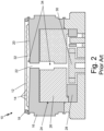
- FIG. 2 is a schematic cross-sectional side view of prior art pressure sensor 10.
- Pressure sensor 10 includes isolator 12 with corrugations 14, header 16, and weld ring 18.
- Header 16 includes dished isolator support 20 (shown in FIG. 2 ) with hole 22 (shown in FIG. 2 ) and cylindrical cavity 24 (shown in FIG. 2 ).
- Pressure sensor 10 also includes first filler material 26 (shown in FIG. 2 ), second filler material 28 (shown in FIG. 2 ), pressure sensing element 30, gap 32 (shown in FIG. 2 ), and oil 34 (shown in FIG. 2 ).
- FIG. 1B also includes area C and area P of isolator 12.
- Pressure sensor 10 has isolator 12, which is a thin disc of metal stamped to include corrugations 14. Header 16 acts as a housing for components of pressure sensor 10. Header is made of metal. Isolator 12 is positioned over a top of header 16. Isolator 12 and header 16 are welded together with weld ring 18. Header 16 has dished isolator support 20 located at the top of header 16 under isolator 12. Dished isolator support 20 is concave to isolator 12 such that a middle of dished isolator support 20 is farther away from isolator 12 than an edge of dished isolator support 20. Header 16 includes hole 22 through dished isolator support 20 near the middle of dished isolator support 20. Cavity 24 is a cylindrical space in header 16.
- First filler material 26 and second filler material 28 are positioned in cavity 24. First filler material 26 and second filler material 28 can be adhered to one another and to header 26. First filler material 26 has a central channel aligned with hole 22. Second filler material 28 is designed to fit around pressure sensing element 30, which is near a bottom of cavity 24. Pressure sensing element 30 is electrically connected to other elements to transmit sensed pressure readings. Pressure sensing element 30 can be any appropriate pressure sensing element, including a strain gauge or a micro electro-mechanical systems (MEMS) device.
- MEMS micro electro-mechanical systems
- Pressure sensor 10 also has gap 32 between a bottom of isolator 12 and a top of dished isolator support 20. Gap 32 is wider near the middle of dished isolator support 20 and narrower near the edge of dished isolator support 20. Pressure sensor 10 is filled with oil 34, including in gap 32, hole 22, the channel in first filler material 28, and partially surrounding pressure sensing element 30. Oil 34 can move between gap 32, hole 22, the channel in first filler material 28, and around pressure sensing element 30.
- Pressure sensor 10 can be used to make pressure measurements of fluid in contact with isolator 12.
- pressure sensor 10 can be installed in a port of a hydraulic braking system such that hydraulic fluid in the braking system can interact with isolator 12.
- Hydraulic brake systems can have pressures upwards of 4,000 PSI where pressure sensor 10 is located.
- isolator 12 When pressure is exerted on isolator 12 (for example, by engaging the braking system), it moves from a neutral state to a depressed state. In the depressed state, isolator 12 is close to or touching dished isolator support 20. In the neutral state (shown in FIG. 2 ), isolator 12 is away from dished isolator support 20 and generally flat across the top of header 16. Movement of isolator 12 moves oil 34 between gap 32 and cavity 24. Hole 22 in dished isolator support 20 allows for oil 34 to move between gap 32 and cavity 24 through dished isolator support 20. Pressure sensing element 30 registers pressure changes from oil 34 movement between gap 32 and cavity 24. The pressure signal can then be transmitted from the pressure sensing element 30.
- Pressure sensor 10 operates in a wide range of temperatures.
- Isolator 12 has corrugations 14 that ensure repeatable and linear sensor behavior over multiple temperatures. Corrugations 14 accomplish this by allowing isolator 10 to move as oil 34 expands and contracts with temperature changes.
- First filler material 26 and second filler material 28 decrease the amount of oil 34 needed to fill pressure sensor 10, which reduces volume changes with temperature fluctuations. This increases accuracy of temperature calibrations and allows for linear pressure measurements at multiple temperatures.
- Dynamic pressure events can move isolator 12 against dished isolator support 20.
- Dished isolator support 20 has a flat surface, which is mismatched with corrugations 14 on isolator 12. The mismatched shapes cause crush and puncture damage during dynamic pressure events.
- Dynamic pressure events pressure events that are high pressure and cause non-uniform pressure distribution on isolator 12
- Corrugations 14 on isolator 12 can crush, as shown in area C of FIG. 1B .
- Crushing damage includes deformation of corrugations 14 of isolator 12.
- Isolator 12 can also be punctured, as shown in area P of FIG. 1B . Puncture damage can include a dimple or a perforation in isolator 12.
- Crush and puncture damage occur when isolator 12 quickly and/or unevenly moves into the depressed state. Crush and puncture damage can also occur when isolator 12 collides with dished isolator support 20. Damage, like crushing and puncturing, reduces performance of pressure sensor 10, including decreased sensitivity, accuracy, and precision. If pressure sensor 10 experiences multiple dynamic pressure events, pressure sensor 10 will experience accumulated output degradation.
- the curved shape of dished isolator support 20 allows for gap 32 to hold more oil 34. Additional oil 34 theoretically cushions isolator 12. However, the additional oil 34 in gap 32 reduces the accuracy of temperature calibration of pressure sensor 10. This reduces performance of pressure sensor 10 at different temperatures. Further, isolator 12 still sustains crush and/or puncture damage at high pressures. Hole 22, while necessary for pressure sending in pressure sensor 10, allows for volumes of oil 34 to move beneath a center of isolator 12 and creates instability which can lead to puncture damage.
- FIG. 3 is a perspective view of pressure sensor 110.
- FIG. 4 is an exploded view of pressure sensor 110.
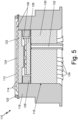
- FIG. 5 is a schematic cross-sectional side view of pressure sensor 110.
- Pressure sensor 110 includes isolator 112 with corrugations 114, header 116 with cavity 118 (shown in FIG. 5 ), and weld ring 120.
- Pressure sensor 110 also includes corrugated isolator support 122 (shown in FIGS. 4-5 ), gap 124 (shown in FIG. 5 ), filler material 126 (shown in FIGS. 4-5 ), pressure sensing element 128 (shown in FIGS. 4-5 ), plug 130 (shown in FIGS. 4-5 ), electrical connections 132 (shown in FIG. 5 ), s-pins 134 (shown in FIGS. 4-5 ), and oil 134 (shown in FIG. 5 ).
- Pressure sensor 110 can be used, for example, with a hydraulic braking system on an aircraft.
- Isolator 112 is a foil disc stamped with corrugations 114. Isolator 112 is approximately 0.001 inch thick. Isolator 112 is made of a metal. Isolator 112 is mounted on a top of header 116, which is a housing for pressure sensor 110. Within header 116 is cylindrical cavity 118. Isolator 112 is held to the top of header 116 by weld ring 120. Weld ring 120, isolator 112, and header 116 are all welded together.
- Corrugated isolator support 122 is positioned inside cylindrical cavity 118 near a top of header 116. Corrugated isolator support 122 has corrugations that align with corrugations 114 on isolator 112. Corrugated isolator support 122 is made from a material with a low coefficient of thermal expansion (CTE). Example materials with a low CTE include polyetherimide, glass fibers, resin, plastic, and combinations thereof. Between isolator 112 and corrugated isolator support 122 is gap 124. Gap 124 has a constant width between isolator 112 and corrugated isolator support 122. The width of gap 124 is between 0.005 inches and 0.020 inches. The width of gap 124 is preferably 0.007 inches.
- Filler material 126, pressure sensing element 128, and plug 130 are also positioned within cavity 118 below corrugated isolator support 122. Filler material 126 is adhered to a bottom of corrugated isolator support 122 and a top of glass plug 130. Filler material 126 is made of a material with a low CTE, for example, polyetherimide, glass fibers, resin, plastic, and combinations thereof. Filler material 126 has a generally cylindrical shape to fit tightly into cavity 118. An inner portion of filler material 126 has a generally toroidal shape with an inner perimeter that matches pressure sensing element 128. Pressure sensing element 128 is positioned inside filler material 126. Pressure sensing element 128 is a strain gauge.
- Pressure sensor 128 can alternatively be a MEMS device or other stress sensor gauge.
- Plug 130 encloses a bottom of cavity 118. Pressure sensing element 128 and filler material 126 are both adhered to plug 130.
- Plug 130 is made of glass.
- Plug 130 is electrically insulating and hermetically seals cavity 118. Other materials, for example resin, rubber, and plastic can be used to make plug 130.
- Electrical connections 132 connect to pressure sensing element 128 and run through plug 130 to transmit information regarding the sensed pressure readings to other components.
- S-pins 134 are in a bottom of plug 130 to secure pressure sensor 110.
- Oil 136 fills gap 124 and portions of cavity 118 not filled by corrugated isolator support 122, filler material 126, pressure sensor 128, and plug 130.
- Oil 136 is silicone oil, but can be any other oil. Oil 136 can move between gap 124 and cavity 118 via a channel in a side of isolator 112 and/or a channel in filler material 126.
- Pressure sensor 110 uses isolator 112 to transmit external pressure to internal pressure sensing element 128.
- isolator 112 moves to a depressed state and moves oil 136 into cavity 118.
- the increased amount of oil 136 in cavity 118 is sensed by pressure sensing element 128.
- Pressure sensing element 128 transmits electrical signals indicating the sensed pressure to other components through electrical connections 132.
- Filler material 126 and corrugated isolator support 122 reduce the volume of cavity 118 and the amount of oil 134 needed to operate pressure sensor 110. Reducing the amount of oil 134 in cavity 118 and gap 124 reduces temperature-related volume fluctuations in pressure sensor 110 and makes calibration and pressure measurements more accurate.
- Corrugated isolator support 122 protects isolator 112 from crush and puncture damage due to its shape matching corrugations 114.
- a center of isolator 112 is designed to contact corrugated isolator support 122 first before permanent deformation of isolator 112 occurs.
- Corrugated isolator support 122 does not have a hole in the middle (like dished isolator support 20 shown in FIG. 2 ), which supports the center of isolator 112 and reduces puncture damage.
- the center of isolator 112 is supported by the matching, flat surface of a center of corrugated isolator support.
- corrugations on corrugated isolator support 122 match corrugations 114 on isolator 112 and support corrugations 114 from crush damage (as shown at C in FIG. 1B ).
- the matching shape of corrugated isolator support 122 with isolator 112 maximizes contact between isolator 112 and corrugated isolator support 122. This prevents damage during dynamic pressure events by minimizing pressure exerted only on isolator 112.
- Corrugated isolator support 122 can prevent damage to isolator 112 even when dynamic pressure events exert up to 11,000 PSI on pressure sensor 110.
- the constant width of gap 124 protects isolator 112 from damage by acting as a hydrodynamic dampener.
- the constant width of gap 124 provides hydrodynamic resistance to prevent isolator 112 from being damaged during dynamic pressure events.
- the small size of the constant width of gap 124 also reduces the distance the center of isolator 112 must travel.
- corrugated isolator support 122 and gap 124 reduce the likelihood of damage to isolator 112 during dynamic pressure events. This allows pressure sensor 110 to sense over its entire useful range even after multiple dynamic pressure events that would damage isolator 12 in pressure sensor 10 (as discussed in relation to FIGS. 1A-2 ).
- a pressure sensor includes a header with a cavity, a pressure sensing element, an isolator, an isolator support, a damping gap, and oil.
- the pressure sensing element is in the cavity.
- the isolator has corrugations and is mounted to a top of the header.
- the isolator covers the cavity.
- the isolator support is in the cavity of the header above the pressure sensing element.
- the isolator support is corrugated.
- the corrugations of the isolator support align with the corrugations on the isolator.
- the damping gap is between the isolator support and the isolator.
- the damping gap has a constant width between the isolator support and the isolator. Oil fills the damping gap and the cavity in the header. The oil moves between the damping gap and the header cavity in response to external pressure changes moving the isolator.
- the pressure sensor of the preceding paragraph can optionally include, additionally and/or alternatively, any one or more of the following features, configurations and/or additional components:
- a further embodiment of the foregoing pressure sensor and also including an isolator weld ring around an edge of the isolator and welded to the top of the header to mount the isolator onto the header.
- a further embodiment of any of the foregoing pressure sensors and also including a plug positioned in the header cavity to support the pressure sensing element and to seal the cavity.
- the plug is a glass plug with s-pins.
- the filler material has a cavity shaped to fit the pressure sensing element.
- the pressure sensor is positioned inside the filler material.
- the isolator support is adhered to a top of the filler material.
- filler material and the isolator support are made of a material with a low coefficient of thermal expansion chosen from the group consisting of polyetherimide, glass fibers, resin, plastic, and combinations thereof.
- damping gap is between 0.005 inches (0.127 millimeters) and 0.020 inches (0.508 millimeters).
- pressure sensing element is a micro electro-mechanical systems (MEMS) device.
- MEMS micro electro-mechanical systems
Landscapes
- Physics & Mathematics (AREA)
- General Physics & Mathematics (AREA)
- Health & Medical Sciences (AREA)
- Child & Adolescent Psychology (AREA)
- Measuring Fluid Pressure (AREA)
Abstract
Description
- This application relates to pressure sensors and, more specifically, pressure sensors utilizing corrugated foil disc isolators.
- Pressure sensors with isolators utilize oil inside of a header, or housing, to sense surrounding pressure in hydraulic systems. The isolator protects a sensing element in the pressure sensor from damage caused by direct interaction with the hydraulic system. Hydraulic fluid exerts pressure on the foil disc isolator causing the oil to move within the pressure sensor, which is sensed by the pressure sensing element. Isolators are corrugated to keep sensor outputs linear over a wide range of operating temperatures.
- Dynamic pressure events include pressure spikes (often above a maximum pressure considered for the pressure sensor) or uneven applications of pressure on the isolator. Dynamic pressure events can crush the corrugations on the isolator or puncture a middle portion of the isolator. Crushed, punctured, and otherwise damaged isolators have decreased sensitivity, accuracy, and precision.
- A pressure sensor includes a header with a cavity, a pressure sensing element, an isolator, an isolator support, a damping gap, and oil. The pressure sensing element is in the cavity. The isolator has corrugations and is mounted to a top of the header. The isolator covers the cavity. The isolator support is in the cavity of the header above the pressure sensing element. The isolator support is corrugated. The corrugations of the isolator support align with the corrugations on the isolator. The damping gap is between the isolator support and the isolator. The damping gap has a constant width between the isolator support and the isolator. Oil fills the damping gap and the cavity in the header. The oil moves between the damping gap and the header cavity in response to external pressure changes moving the isolator.
-
-
FIG. 1A is a perspective view of a prior art pressure sensor. -
FIG. 1B is a perspective view of the prior art pressure sensor after a dynamic pressure event. -
FIG. 2 is a schematic cross-sectional side view of the prior art pressure sensor. -
FIG. 3 is a perspective view of a pressure sensor. -
FIG. 4 is an exploded view of the pressure sensor ofFIG. 3 . -
FIG. 5 is a schematic cross-sectional side view of the pressure sensor ofFIG. 3 . -
FIG. 1A is a perspective view of priorart pressure sensor 10.FIG. 1B is a perspective view of damaged priorart pressure sensor 10 after a dynamic pressure event.FIG. 2 is a schematic cross-sectional side view of priorart pressure sensor 10.FIGS. 1A, 1B , and2 will be discussed together.Pressure sensor 10 includesisolator 12 withcorrugations 14,header 16, andweld ring 18.Header 16 includes dished isolator support 20 (shown inFIG. 2 ) with hole 22 (shown inFIG. 2 ) and cylindrical cavity 24 (shown inFIG. 2 ).Pressure sensor 10 also includes first filler material 26 (shown inFIG. 2 ), second filler material 28 (shown inFIG. 2 ),pressure sensing element 30, gap 32 (shown inFIG. 2 ), and oil 34 (shown inFIG. 2 ).FIG. 1B also includes area C and area P ofisolator 12. -
Pressure sensor 10 hasisolator 12, which is a thin disc of metal stamped to includecorrugations 14.Header 16 acts as a housing for components ofpressure sensor 10. Header is made of metal.Isolator 12 is positioned over a top ofheader 16.Isolator 12 andheader 16 are welded together withweld ring 18.Header 16 has dishedisolator support 20 located at the top ofheader 16 underisolator 12. Dishedisolator support 20 is concave toisolator 12 such that a middle of dishedisolator support 20 is farther away fromisolator 12 than an edge of dishedisolator support 20.Header 16 includeshole 22 through dishedisolator support 20 near the middle of dishedisolator support 20.Cavity 24 is a cylindrical space inheader 16. -
First filler material 26 andsecond filler material 28 are positioned incavity 24.First filler material 26 andsecond filler material 28 can be adhered to one another and to header 26.First filler material 26 has a central channel aligned withhole 22.Second filler material 28 is designed to fit aroundpressure sensing element 30, which is near a bottom ofcavity 24.Pressure sensing element 30 is electrically connected to other elements to transmit sensed pressure readings.Pressure sensing element 30 can be any appropriate pressure sensing element, including a strain gauge or a micro electro-mechanical systems (MEMS) device. -
Pressure sensor 10 also hasgap 32 between a bottom ofisolator 12 and a top of dishedisolator support 20.Gap 32 is wider near the middle of dished isolator support 20 and narrower near the edge of dishedisolator support 20.Pressure sensor 10 is filled withoil 34, including ingap 32,hole 22, the channel infirst filler material 28, and partially surroundingpressure sensing element 30.Oil 34 can move betweengap 32,hole 22, the channel infirst filler material 28, and aroundpressure sensing element 30. -
Pressure sensor 10 can be used to make pressure measurements of fluid in contact withisolator 12. For example,pressure sensor 10 can be installed in a port of a hydraulic braking system such that hydraulic fluid in the braking system can interact withisolator 12. Hydraulic brake systems can have pressures upwards of 4,000 PSI wherepressure sensor 10 is located. - When pressure is exerted on isolator 12 (for example, by engaging the braking system), it moves from a neutral state to a depressed state. In the depressed state,
isolator 12 is close to or touching dishedisolator support 20. In the neutral state (shown inFIG. 2 ),isolator 12 is away from dishedisolator support 20 and generally flat across the top ofheader 16. Movement ofisolator 12moves oil 34 betweengap 32 andcavity 24.Hole 22 in dishedisolator support 20 allows foroil 34 to move betweengap 32 andcavity 24 through dishedisolator support 20.Pressure sensing element 30 registers pressure changes fromoil 34 movement betweengap 32 andcavity 24. The pressure signal can then be transmitted from thepressure sensing element 30. -
Pressure sensor 10 operates in a wide range of temperatures.Isolator 12 has corrugations 14 that ensure repeatable and linear sensor behavior over multiple temperatures.Corrugations 14 accomplish this by allowingisolator 10 to move asoil 34 expands and contracts with temperature changes.First filler material 26 andsecond filler material 28 decrease the amount ofoil 34 needed to fillpressure sensor 10, which reduces volume changes with temperature fluctuations. This increases accuracy of temperature calibrations and allows for linear pressure measurements at multiple temperatures. - Dynamic pressure events can move isolator 12 against dished
isolator support 20. Dishedisolator support 20 has a flat surface, which is mismatched withcorrugations 14 onisolator 12. The mismatched shapes cause crush and puncture damage during dynamic pressure events. Dynamic pressure events (pressure events that are high pressure and cause non-uniform pressure distribution on isolator 12) can damageisolator 12.Corrugations 14 onisolator 12 can crush, as shown in area C ofFIG. 1B . Crushing damage includes deformation ofcorrugations 14 ofisolator 12.Isolator 12 can also be punctured, as shown in area P ofFIG. 1B . Puncture damage can include a dimple or a perforation inisolator 12. Crush and puncture damage occur whenisolator 12 quickly and/or unevenly moves into the depressed state. Crush and puncture damage can also occur whenisolator 12 collides with dishedisolator support 20. Damage, like crushing and puncturing, reduces performance ofpressure sensor 10, including decreased sensitivity, accuracy, and precision. Ifpressure sensor 10 experiences multiple dynamic pressure events,pressure sensor 10 will experience accumulated output degradation. - The curved shape of dished
isolator support 20 allows forgap 32 to holdmore oil 34.Additional oil 34 theoretically cushionsisolator 12. However, theadditional oil 34 ingap 32 reduces the accuracy of temperature calibration ofpressure sensor 10. This reduces performance ofpressure sensor 10 at different temperatures. Further,isolator 12 still sustains crush and/or puncture damage at high pressures.Hole 22, while necessary for pressure sending inpressure sensor 10, allows for volumes ofoil 34 to move beneath a center ofisolator 12 and creates instability which can lead to puncture damage. -
FIG. 3 is a perspective view ofpressure sensor 110.FIG. 4 is an exploded view ofpressure sensor 110.FIG. 5 is a schematic cross-sectional side view ofpressure sensor 110.FIGS. 3-5 will be discussed together.Pressure sensor 110 includesisolator 112 withcorrugations 114,header 116 with cavity 118 (shown inFIG. 5 ), andweld ring 120.Pressure sensor 110 also includes corrugated isolator support 122 (shown inFIGS. 4-5 ), gap 124 (shown inFIG. 5 ), filler material 126 (shown inFIGS. 4-5 ), pressure sensing element 128 (shown inFIGS. 4-5 ), plug 130 (shown inFIGS. 4-5 ), electrical connections 132 (shown inFIG. 5 ), s-pins 134 (shown inFIGS. 4-5 ), and oil 134 (shown inFIG. 5 ). -
Pressure sensor 110 can be used, for example, with a hydraulic braking system on an aircraft.Isolator 112 is a foil disc stamped withcorrugations 114.Isolator 112 is approximately 0.001 inch thick.Isolator 112 is made of a metal.Isolator 112 is mounted on a top ofheader 116, which is a housing forpressure sensor 110. Withinheader 116 iscylindrical cavity 118.Isolator 112 is held to the top ofheader 116 byweld ring 120.Weld ring 120,isolator 112, andheader 116 are all welded together. -
Corrugated isolator support 122 is positioned insidecylindrical cavity 118 near a top ofheader 116.Corrugated isolator support 122 has corrugations that align withcorrugations 114 onisolator 112.Corrugated isolator support 122 is made from a material with a low coefficient of thermal expansion (CTE). Example materials with a low CTE include polyetherimide, glass fibers, resin, plastic, and combinations thereof. Between isolator 112 andcorrugated isolator support 122 isgap 124.Gap 124 has a constant width betweenisolator 112 andcorrugated isolator support 122. The width ofgap 124 is between 0.005 inches and 0.020 inches. The width ofgap 124 is preferably 0.007 inches. -
Filler material 126,pressure sensing element 128, and plug 130 are also positioned withincavity 118 belowcorrugated isolator support 122.Filler material 126 is adhered to a bottom ofcorrugated isolator support 122 and a top ofglass plug 130.Filler material 126 is made of a material with a low CTE, for example, polyetherimide, glass fibers, resin, plastic, and combinations thereof.Filler material 126 has a generally cylindrical shape to fit tightly intocavity 118. An inner portion offiller material 126 has a generally toroidal shape with an inner perimeter that matchespressure sensing element 128.Pressure sensing element 128 is positioned insidefiller material 126.Pressure sensing element 128 is a strain gauge.Pressure sensor 128 can alternatively be a MEMS device or other stress sensor gauge.Plug 130 encloses a bottom ofcavity 118.Pressure sensing element 128 andfiller material 126 are both adhered to plug 130.Plug 130 is made of glass.Plug 130 is electrically insulating and hermetically sealscavity 118. Other materials, for example resin, rubber, and plastic can be used to makeplug 130.Electrical connections 132 connect to pressuresensing element 128 and run throughplug 130 to transmit information regarding the sensed pressure readings to other components. S-pins 134 are in a bottom ofplug 130 to securepressure sensor 110. -
Oil 136 fillsgap 124 and portions ofcavity 118 not filled bycorrugated isolator support 122,filler material 126,pressure sensor 128, and plug 130.Oil 136 is silicone oil, but can be any other oil.Oil 136 can move betweengap 124 andcavity 118 via a channel in a side ofisolator 112 and/or a channel infiller material 126. -
Pressure sensor 110 uses isolator 112 to transmit external pressure to internalpressure sensing element 128. When pressure is exerted onisolator 112,isolator 112 moves to a depressed state and movesoil 136 intocavity 118. The increased amount ofoil 136 incavity 118 is sensed bypressure sensing element 128.Pressure sensing element 128 transmits electrical signals indicating the sensed pressure to other components throughelectrical connections 132. -
Filler material 126 andcorrugated isolator support 122 reduce the volume ofcavity 118 and the amount ofoil 134 needed to operatepressure sensor 110. Reducing the amount ofoil 134 incavity 118 andgap 124 reduces temperature-related volume fluctuations inpressure sensor 110 and makes calibration and pressure measurements more accurate. -
Corrugated isolator support 122 protects isolator 112 from crush and puncture damage due to itsshape matching corrugations 114. A center ofisolator 112 is designed to contactcorrugated isolator support 122 first before permanent deformation ofisolator 112 occurs.Corrugated isolator support 122 does not have a hole in the middle (like dishedisolator support 20 shown inFIG. 2 ), which supports the center ofisolator 112 and reduces puncture damage. The center ofisolator 112 is supported by the matching, flat surface of a center of corrugated isolator support. The corrugations oncorrugated isolator support 122match corrugations 114 onisolator 112 andsupport corrugations 114 from crush damage (as shown at C inFIG. 1B ). The matching shape ofcorrugated isolator support 122 withisolator 112 maximizes contact betweenisolator 112 andcorrugated isolator support 122. This prevents damage during dynamic pressure events by minimizing pressure exerted only onisolator 112.Corrugated isolator support 122 can prevent damage toisolator 112 even when dynamic pressure events exert up to 11,000 PSI onpressure sensor 110. - Further, the constant width of
gap 124 protects isolator 112 from damage by acting as a hydrodynamic dampener. The constant width ofgap 124 provides hydrodynamic resistance to prevent isolator 112 from being damaged during dynamic pressure events. The small size of the constant width ofgap 124 also reduces the distance the center ofisolator 112 must travel. By quickly contactingcorrugated isolator support 120, the middle ofisolator 112 receives mechanical support prior to permanent deformation (for example, crush damage shown at C inFIG. 1B ) and is less likely to sustain puncture damage (for example, puncture damage shown at P inFIG. 1B ). - The combination of
corrugated isolator support 122 andgap 124 reduce the likelihood of damage toisolator 112 during dynamic pressure events. This allowspressure sensor 110 to sense over its entire useful range even after multiple dynamic pressure events that would damageisolator 12 in pressure sensor 10 (as discussed in relation toFIGS. 1A-2 ). - The following are non-exclusive descriptions of possible embodiments of the present invention.
- A pressure sensor includes a header with a cavity, a pressure sensing element, an isolator, an isolator support, a damping gap, and oil. The pressure sensing element is in the cavity. The isolator has corrugations and is mounted to a top of the header. The isolator covers the cavity. The isolator support is in the cavity of the header above the pressure sensing element. The isolator support is corrugated. The corrugations of the isolator support align with the corrugations on the isolator. The damping gap is between the isolator support and the isolator. The damping gap has a constant width between the isolator support and the isolator. Oil fills the damping gap and the cavity in the header. The oil moves between the damping gap and the header cavity in response to external pressure changes moving the isolator.
- The pressure sensor of the preceding paragraph can optionally include, additionally and/or alternatively, any one or more of the following features, configurations and/or additional components:
- A further embodiment of the foregoing pressure sensor, and also including an isolator weld ring around an edge of the isolator and welded to the top of the header to mount the isolator onto the header.
- A further embodiment of any of the foregoing pressure sensors, and also including a plug positioned in the header cavity to support the pressure sensing element and to seal the cavity. The plug is a glass plug with s-pins.
- A further embodiment of any of the foregoing pressure sensors, electrical connections routed through the plug and connected to the pressure sensing element.
- A further embodiment of any of the foregoing pressure sensors, wherein the plug electrically and hermetically seals the cavity.
- A further embodiment of any of the foregoing pressure sensors, and also including filler material within the cavity of the header. The filler material has a cavity shaped to fit the pressure sensing element. The pressure sensor is positioned inside the filler material. The isolator support is adhered to a top of the filler material.
- A further embodiment of any of the foregoing pressure sensors, wherein the cavity of the filler material is toroidal.
- A further embodiment of any of the foregoing pressure sensors, wherein the filler material and the isolator support are made of a material with a low coefficient of thermal expansion chosen from the group consisting of polyetherimide, glass fibers, resin, plastic, and combinations thereof.
- A further embodiment of any of the foregoing pressure sensors, wherein the oil is silicone oil.
- A further embodiment of any of the foregoing pressure sensors, wherein the damping gap is between 0.005 inches (0.127 millimeters) and 0.020 inches (0.508 millimeters).
- A further embodiment of any of the foregoing pressure sensors, wherein the damping gap is 0.007 inches (0.178 millimeters).
- A further embodiment of any of the foregoing pressure sensors, wherein the pressure sensing element is a strain gauge.
- A further embodiment of any of the foregoing pressure sensors, wherein the pressure sensing element is a micro electro-mechanical systems (MEMS) device.
- A further embodiment of any of the foregoing pressure sensors, wherein the cavity is cylindrical.
- A further embodiment of any of the foregoing pressure sensors, wherein the isolator is made of a metal foil.
- While the invention has been described with reference to an exemplary embodiment(s), it will be understood by those skilled in the art that various changes may be made and equivalent embodiment(s) may be substituted for elements thereof without departing from the scope of the invention. In addition, many modifications may be made to adapt a particular situation or material to the teachings of the invention without departing from the essential scope thereof. Therefore, it is intended that the invention not be limited to the particular embodiment(s) disclosed, but that the invention will include all embodiments falling within the scope of the appended claims.
Claims (14)
- A pressure sensor comprising:a header (116) with a cavity;a pressure sensing element (128) in the cavity;an isolator with corrugations mounted to a top of the header (116) covering the cavity;an isolator support in the cavity of the header (116) above the pressure sensing element (128), wherein the isolator support is corrugated, and wherein the corrugations of the isolator support align with the corrugations on the isolator;a damping gap between the isolator support and the isolator, wherein the damping gap has a constant width between the isolator and the isolator support; andoil filling the damping gap and the cavity in the header (116), wherein the oil moves between the damping gap and the header cavity in response to external pressure changes moving the isolator.
- The pressure sensor of claim 1, and further comprising:
an isolator weld ring around an edge of the isolator and welded to the top of the header (116) to mount the isolator onto the header (116). - The pressure sensor of claim 1 or 2, and further comprising:a plug positioned in the header cavity to support the pressure sensing element (128) and to seal the cavity, wherein the plug is a glass plug with s-pins; andelectrical connections routed through the plug and connected to the pressure sensing element (128).
- The pressure sensor of claim 3, wherein the plug electrically and hermetically seals the cavity.
- The pressure sensor of any preceding claim, and further comprising:filler material within the cavity of the header (116), wherein the filler material has a cavity shaped to fit the pressure sensing element (128);wherein the pressure sensor is positioned inside the filler material; andwherein the isolator support is adhered to a top of the filler material.
- The pressure sensor of claim 5, wherein the cavity of the filler material is a toroid.
- The pressure sensor of claim 5, wherein the filler material and the isolator support are made of a material with a low coefficient of thermal expansion chosen from the group consisting of polyetherimide, glass fibers, resin, plastic, and combinations thereof.
- The pressure sensor of any preceding claim, wherein the oil is silicone oil.
- The pressure sensor of any preceding claim, wherein the damping gap is between 0.005 inches (0.127 millimeters) and 0.020 inches (0.508 millimeters).
- The pressure sensor of any of claims 1 to 8, wherein the damping gap is 0.007 inches (0.178 millimeters).
- The pressure sensor of any preceding claim, wherein the pressure sensing element (128) is a strain gauge.
- The pressure sensor of any of claims 1 to 10, wherein the pressure sensing element (128) is a micro electro-mechanical systems (MEMS) device.
- The pressure sensor of any preceding claim, wherein the cavity is cylindrical.
- The pressure sensor of any preceding claim, wherein the isolator is made of a metal foil.
Applications Claiming Priority (1)
| Application Number | Priority Date | Filing Date | Title |
|---|---|---|---|
| US18/088,181 US12259290B2 (en) | 2022-12-23 | 2022-12-23 | Pressure sensor with corrugated isolator support |
Publications (2)
| Publication Number | Publication Date |
|---|---|
| EP4390356A1 true EP4390356A1 (en) | 2024-06-26 |
| EP4390356B1 EP4390356B1 (en) | 2026-04-01 |
Family
ID=89386158
Family Applications (1)
| Application Number | Title | Priority Date | Filing Date |
|---|---|---|---|
| EP23220344.8A Active EP4390356B1 (en) | 2022-12-23 | 2023-12-27 | Pressure sensor with corrugated isolator support |
Country Status (2)
| Country | Link |
|---|---|
| US (1) | US12259290B2 (en) |
| EP (1) | EP4390356B1 (en) |
Citations (2)
| Publication number | Priority date | Publication date | Assignee | Title |
|---|---|---|---|---|
| DE20019067U1 (en) * | 2000-11-09 | 2001-01-18 | Abb Patent Gmbh, 68309 Mannheim | Pressure measuring device |
| DE102018131795A1 (en) * | 2018-12-11 | 2020-06-18 | Endress+Hauser SE+Co. KG | Pressure sensor arrangement for determining a pressure of a medium in a hygienic process |
Family Cites Families (10)
| Publication number | Priority date | Publication date | Assignee | Title |
|---|---|---|---|---|
| US3800413A (en) * | 1969-10-27 | 1974-04-02 | Rosemount Inc | Differential pressure transducer |
| US4227418A (en) * | 1979-09-24 | 1980-10-14 | Fischer & Porter Company | Capacitive pressure transducer |
| JPS57500797A (en) | 1980-06-12 | 1982-05-06 | ||
| US4798089A (en) * | 1987-03-12 | 1989-01-17 | Rosemount Inc. | Isolator apparatus |
| SG43766A1 (en) * | 1993-04-23 | 1997-11-14 | Rosemount Inc | Pressure isolator assembly for sanitary processing |
| DE102008037736A1 (en) | 2008-08-14 | 2010-02-18 | Witzenmann Gmbh | Pressures and/or pressure changes detecting device e.g. high pressure-resistant control element, has base part forming boundary for deformation of membrane, where membrane is provided with corrugated profile |
| DE102012113042A1 (en) | 2012-12-21 | 2014-06-26 | Endress + Hauser Gmbh + Co. Kg | Hydraulic measuring unit with coplanar pressure inputs and differential pressure sensor with such a measuring unit |
| US10203255B2 (en) * | 2016-08-25 | 2019-02-12 | Measurement Specialties, Inc. | Differential pressure sensor incorporating common mode error compensation |
| US10371591B2 (en) * | 2016-11-11 | 2019-08-06 | Measurement Specialties, Inc. | Method and apparatus for correction of pressure sensors |
| US11662263B2 (en) | 2021-03-30 | 2023-05-30 | Rosemount Aerospace Inc. | Pressure sensor for preventing fluid jetting |
-
2022
- 2022-12-23 US US18/088,181 patent/US12259290B2/en active Active
-
2023
- 2023-12-27 EP EP23220344.8A patent/EP4390356B1/en active Active
Patent Citations (2)
| Publication number | Priority date | Publication date | Assignee | Title |
|---|---|---|---|---|
| DE20019067U1 (en) * | 2000-11-09 | 2001-01-18 | Abb Patent Gmbh, 68309 Mannheim | Pressure measuring device |
| DE102018131795A1 (en) * | 2018-12-11 | 2020-06-18 | Endress+Hauser SE+Co. KG | Pressure sensor arrangement for determining a pressure of a medium in a hygienic process |
Non-Patent Citations (1)
| Title |
|---|
| HOHLFELD O ET AL: "Miniature hermetically sealed housing for pressure sensors", MECHATRONICS, PERGAMON PRESS, OXFORD, GB, vol. 12, no. 9-10, 1 November 2002 (2002-11-01), pages 1201 - 1212, XP004374267, ISSN: 0957-4158, DOI: 10.1016/S0957-4158(02)00024-7 * |
Also Published As
| Publication number | Publication date |
|---|---|
| EP4390356B1 (en) | 2026-04-01 |
| US12259290B2 (en) | 2025-03-25 |
| US20240210263A1 (en) | 2024-06-27 |
Similar Documents
| Publication | Publication Date | Title |
|---|---|---|
| EP2458361B1 (en) | Pressure-sensor device | |
| AU757148B2 (en) | Force sensor assembly | |
| KR20110134308A (en) | Hermetic Pressure Sensing Device | |
| US9291514B2 (en) | Pressure sensor having a compressible element | |
| EP2156157B1 (en) | Differential pressure sensor | |
| US4173149A (en) | Differential pressure sensing devices | |
| US9217685B2 (en) | Pressure sensor having a compressible element | |
| US20150185102A1 (en) | Leadless oil filled pressure transducer | |
| US5999082A (en) | Compensated oil-filled pressure transducers | |
| GB2370638A (en) | Pressure-measuring device | |
| US8770032B2 (en) | Relative pressure sensor | |
| US4809555A (en) | Pressure sensor | |
| US12259290B2 (en) | Pressure sensor with corrugated isolator support | |
| US9316551B2 (en) | Torque insensitive header assembly | |
| CN223664161U (en) | Pressure sensor packaging structure | |
| JP4186824B2 (en) | Differential pressure measuring device | |
| RU2831518C1 (en) | Differential pressure sensor with overpressure protection | |
| JP2011252739A (en) | Pressure detecting device | |
| KR101200751B1 (en) | Pressure sensor | |
| JPS6333150Y2 (en) | ||
| JPH0436425Y2 (en) | ||
| JP3333703B2 (en) | Pressure sensor and method of manufacturing pressure sensor | |
| JPH04319636A (en) | Pressure difference transmitter | |
| JP2009192288A (en) | Differential pressure / pressure transmitter and manufacturing method thereof | |
| JPH0476430A (en) | Differential pressure measuring device |
Legal Events
| Date | Code | Title | Description |
|---|---|---|---|
| PUAI | Public reference made under article 153(3) epc to a published international application that has entered the european phase |
Free format text: ORIGINAL CODE: 0009012 |
|
| STAA | Information on the status of an ep patent application or granted ep patent |
Free format text: STATUS: THE APPLICATION HAS BEEN PUBLISHED |
|
| AK | Designated contracting states |
Kind code of ref document: A1 Designated state(s): AL AT BE BG CH CY CZ DE DK EE ES FI FR GB GR HR HU IE IS IT LI LT LU LV MC ME MK MT NL NO PL PT RO RS SE SI SK SM TR |
|
| STAA | Information on the status of an ep patent application or granted ep patent |
Free format text: STATUS: REQUEST FOR EXAMINATION WAS MADE |
|
| 17P | Request for examination filed |
Effective date: 20241223 |
|
| GRAP | Despatch of communication of intention to grant a patent |
Free format text: ORIGINAL CODE: EPIDOSNIGR1 |
|
| STAA | Information on the status of an ep patent application or granted ep patent |
Free format text: STATUS: GRANT OF PATENT IS INTENDED |
|
| INTG | Intention to grant announced |
Effective date: 20251128 |
|
| GRAS | Grant fee paid |
Free format text: ORIGINAL CODE: EPIDOSNIGR3 |
|
| GRAA | (expected) grant |
Free format text: ORIGINAL CODE: 0009210 |
|
| STAA | Information on the status of an ep patent application or granted ep patent |
Free format text: STATUS: THE PATENT HAS BEEN GRANTED |
|
| AK | Designated contracting states |
Kind code of ref document: B1 Designated state(s): AL AT BE BG CH CY CZ DE DK EE ES FI FR GB GR HR HU IE IS IT LI LT LU LV MC ME MK MT NL NO PL PT RO RS SE SI SK SM TR |
|
| REG | Reference to a national code |
Ref country code: CH Ref legal event code: F10 Free format text: ST27 STATUS EVENT CODE: U-0-0-F10-F00 (AS PROVIDED BY THE NATIONAL OFFICE) Effective date: 20260401 Ref country code: GB Ref legal event code: FG4D |
|
| REG | Reference to a national code |
Ref country code: IE Ref legal event code: FG4D |
|
| REG | Reference to a national code |
Ref country code: DE Ref legal event code: R096 Ref document number: 602023014431 Country of ref document: DE |