EP4390353A1 - Method for estimating or calculating a load on a component - Google Patents
Method for estimating or calculating a load on a component Download PDFInfo
- Publication number
- EP4390353A1 EP4390353A1 EP22214798.5A EP22214798A EP4390353A1 EP 4390353 A1 EP4390353 A1 EP 4390353A1 EP 22214798 A EP22214798 A EP 22214798A EP 4390353 A1 EP4390353 A1 EP 4390353A1
- Authority
- EP
- European Patent Office
- Prior art keywords
- component
- grid
- load
- washer
- interference pattern
- Prior art date
- Legal status (The legal status is an assumption and is not a legal conclusion. Google has not performed a legal analysis and makes no representation as to the accuracy of the status listed.)
- Pending
Links
Images



Classifications
-
- G—PHYSICS
- G01—MEASURING; TESTING
- G01B—MEASURING LENGTH, THICKNESS OR SIMILAR LINEAR DIMENSIONS; MEASURING ANGLES; MEASURING AREAS; MEASURING IRREGULARITIES OF SURFACES OR CONTOURS
- G01B11/00—Measuring arrangements characterised by the use of optical techniques
- G01B11/16—Measuring arrangements characterised by the use of optical techniques for measuring the deformation in a solid, e.g. optical strain gauge
- G01B11/165—Measuring arrangements characterised by the use of optical techniques for measuring the deformation in a solid, e.g. optical strain gauge by means of a grating deformed by the object
-
- B—PERFORMING OPERATIONS; TRANSPORTING
- B25—HAND TOOLS; PORTABLE POWER-DRIVEN TOOLS; MANIPULATORS
- B25B—TOOLS OR BENCH DEVICES NOT OTHERWISE PROVIDED FOR, FOR FASTENING, CONNECTING, DISENGAGING, OR HOLDING
- B25B23/00—Details of, or accessories for, spanners, wrenches, screwdrivers
- B25B23/14—Arrangement of torque limiters or torque indicators in wrenches or screwdrivers
-
- F—MECHANICAL ENGINEERING; LIGHTING; HEATING; WEAPONS; BLASTING
- F16—ENGINEERING ELEMENTS AND UNITS; GENERAL MEASURES FOR PRODUCING AND MAINTAINING EFFECTIVE FUNCTIONING OF MACHINES OR INSTALLATIONS; THERMAL INSULATION IN GENERAL
- F16B—DEVICES FOR FASTENING OR SECURING CONSTRUCTIONAL ELEMENTS OR MACHINE PARTS TOGETHER, e.g. NAILS, BOLTS, CIRCLIPS, CLAMPS, CLIPS OR WEDGES; JOINTS OR JOINTING
- F16B31/00—Screwed connections specially modified in view of tensile load; Break-bolts
- F16B31/02—Screwed connections specially modified in view of tensile load; Break-bolts for indicating the attainment of a particular tensile load or limiting tensile load
- F16B31/028—Screwed connections specially modified in view of tensile load; Break-bolts for indicating the attainment of a particular tensile load or limiting tensile load with a load-indicating washer or washer assembly
-
- G—PHYSICS
- G01—MEASURING; TESTING
- G01L—MEASURING FORCE, STRESS, TORQUE, WORK, MECHANICAL POWER, MECHANICAL EFFICIENCY, OR FLUID PRESSURE
- G01L5/00—Apparatus for, or methods of, measuring force, work, mechanical power, or torque, specially adapted for specific purposes
- G01L5/24—Apparatus for, or methods of, measuring force, work, mechanical power, or torque, specially adapted for specific purposes for determining value of torque or twisting moment for tightening a nut or other member which is similarly stressed
- G01L5/243—Apparatus for, or methods of, measuring force, work, mechanical power, or torque, specially adapted for specific purposes for determining value of torque or twisting moment for tightening a nut or other member which is similarly stressed using washers
-
- F—MECHANICAL ENGINEERING; LIGHTING; HEATING; WEAPONS; BLASTING
- F16—ENGINEERING ELEMENTS AND UNITS; GENERAL MEASURES FOR PRODUCING AND MAINTAINING EFFECTIVE FUNCTIONING OF MACHINES OR INSTALLATIONS; THERMAL INSULATION IN GENERAL
- F16B—DEVICES FOR FASTENING OR SECURING CONSTRUCTIONAL ELEMENTS OR MACHINE PARTS TOGETHER, e.g. NAILS, BOLTS, CIRCLIPS, CLAMPS, CLIPS OR WEDGES; JOINTS OR JOINTING
- F16B2200/00—Constructional details of connections not covered for in other groups of this subclass
- F16B2200/95—Constructional details of connections not covered for in other groups of this subclass with markings, colours, indicators or the like
Definitions
- the invention relates to a method for estimating or calculating a load on a component.
- the invention further relates to a data processing device, a fastener tightening device, a computer program, a computer-readable medium, a component, and a bolted joint.
- Bolted joints for instance tensions joints, are widely used structural elements. For many applications, it is important to control the load or preload during installation or to monitor the preload in service.
- Existing systems for preload measurement such as ultrasonic measurement or preload indicating washers, may be complicated.
- the object of the invention is to provide an improved and simple method for estimating or calculating a load on a component.
- the invention provides a method for estimating or calculating a load on a component according to claim 1.
- a data processing device, a fastener tightening device, a computer program, a computer-readable medium, a component, and a bolted joint are subject-matter of the parallel claim.
- the invention provides a method for estimating or calculating a load on a component, the component having a suitably defined grid of a plurality of equidistant lines and/or dots arranged on a surface thereof, the surface being deformable under a load of the component, the method comprising:
- step c) comprises: c1) analyzing the interference pattern analytically and/or by a machine learning algorithm.
- step c) comprises: c2) measuring a calibration curve of the load as a function of a deformation of the component.
- step c) comprises: c3) determining an extrema distance between interference extrema of the interference pattern.
- step b) comprises: b1) capturing the grid of the unloaded component.
- step b) comprises: b2) capturing one or more dimensions of a reference item for reference.
- the reference item preferably does not or does insignificantly deform under the load.
- the grid of the unloaded component and/or the grid of the component under the load is preferably captured along with the one or more dimensions of the reference item.
- the invention provides a data processing device having an image and/or video capture device for capturing an image and/or video and means adapted to execute the steps of the method according to any of the preceding embodiments.
- the invention provides a fastener tightening device for tightening a fastener, comprising the data processing device.
- the invention provides a computer program comprising instructions to cause the data processing device to execute the steps of the method.
- the invention provides a computer-readable medium having stored thereon the computer program.
- the invention provides a component having a grid of a plurality of equidistant lines and/or dots arranged on a surface thereof, the surface being deformable under a load of the component, the grid being defined such that a superimposition of the grid of the component under the load with the grid of the unloaded component leads to an interference pattern, in particular a beat pattern.
- a deformation of the surface leads to a change of a distance between the lines and/or dots of the grid.
- the grid is engraved on the surface, more preferably by a laser, more preferably with a dot density resolution above 1000 dpi.
- the component is configured as a washer.
- the washer has a circumference, particularly a cylindrical circumference, the lines and/or dots of the grid being arranged on said circumference.
- the washer has a top region, the lines and/or dots of the grid being arranged on said top region.
- the washer is designed as a conical washer.
- the lines of the grid are arranged in an axial direction of the washer and/or in a direction of the load.
- the invention provides a bolted joint, particularly a tension joint, clamping two or more clamp components together and including a male threaded fastener secured with a female screw thread, and a washer according to any of the preceding embodiments, the bolted joint clamping the washer.
- Embodiments of the invention preferably have the following advantages and effects:
- a spherical or conical washer may show a relatively large diametrical expansion.
- a grid is engraved into the washer. The grid may deform with the washer when a tension bolt is loaded (preload or actual load).
- Pictures of the undeformed and deformed washer are preferably superimposed in order to obtain an interferometric or interference pattern.
- the interferometric or interference pattern may be analyzed analytically or by artificial intelligence in order to obtain the bolt load.
- the preload measurement may preferably be performed with an application (app) on a mobile device, such as a smartphone.
- Fig. 1 shows an embodiment of a bolted joint 10 in a side view.
- the bolted joint 10 is configured as a tension joint. Further, the bolted joint 10 is configured for clamping two or more clamp components together.
- the bolted joint 10 includes a male threaded fastener 14 and a washer 16.
- the fastener 14 includes a fastener head 18 and a fastener shank 20 having a threaded portion 22.
- the bolted joint 10 includes a female screw thread arranged opposite of the fastener head 18 and capturing the threaded portion 22 of the fastener shank 20. When clamped by the bolted joint 10, the two or more clamp components are clamped between the fastener head 18 and the screw thread.
- the bolted joint 10 is further configured for clamping the washer 16, for example between the two or more clamp components and the fastener head 18.
- Fig. 2 und 3 show the washer 16 in a side view and a top view, respectively.
- the washer 16 has an annular shape with an outer circumference 26, a top region 27a, a bottom region 27b, and a through hole 24.
- the circumference 26 has a cylindrical shape.
- the washer 16 is further designed as a conical washer, i.e., the through hole 24 includes a support surface 27c that extends inclined from the top region 27a to the bottom region 27b.
- the through hole 24 includes a support surface 27c that extends inclined from the top region 27a to the bottom region 27b.
- other shapes of the washer 16 are possible.
- the washer 16 further has a diametrical expansion DE.
- Fig. 4 shows a top region 28 of the bolted joint 10 in a side view
- Fig. 5 shows the circumference 26 of the washer 16 in more detail.
- a grid 30 is arranged on the circumference 26.
- the grid 30 may be engraved on the circumference 26, for example, by a laser.
- the laser can engrave the grid 30 up to a dot density resolution of 1000 dpi or above.
- the grid 30 may be arranged on the circumference 26 by means of any other method with a suitable resolution.
- the grid 30 may be also arranged on the top region 27a of the washer 16.
- the grid 30 includes a plurality of lines 32.
- the lines are straight lines, but any other form of lines 32 or even dots may be possible according to the invention.
- the lines 32 are arranged on the circumference 26 in an axial direction AD of the washer 16 perpendicular to the diametrical expansion DE and in a direction of a load LO. Along the circumference 26, the lines 32 are arranged in an equidistant manner with a distance DL to each other.
- Fig. 6 shows the grid 30 of the unloaded washer 16 while the lower part of Fig. 6 shows the grid 30 of the washer 16 under the load LO.
- the grid 30 is deformed when the washer 16 is under the load LO.
- a reason for this is that the washer 16 or the circumference 26 is deformed under the load LO and the deformation of the circumference 26 leads to a change of the distance DL between the lines 32 of the grid 30.
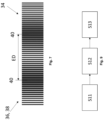
- Fig. 7 shows a superimposition 34 of the grid 30 of the unloaded washer 16 and the grid 30 of the washer 16 under the load LO.
- the superimposition 34 generates an interference pattern 36, particularly a beat pattern 38.
- the interference pattern 36 includes one or more interference extrema 40, i.e., minima and/or maxima.
- the grid 30, e.g., the line distance DL is defined such that the superimposition 34 of the grid 30 of the washer 16 under the load LO with the grid of the unloaded washer 16 leads to such an interference pattern 36 or beat pattern 38.
- the lines 32 may be interpreted as wavefronts and the distance DL between the lines 32 may be interpreted as a wave length which changes when the circumference 26 is deformed.
- the superimposition 34 of two waves with slightly different frequencies leads in general to a beat phenomenon.
- one or more dimensions of a reference item may be needed for reference, wherein the reference item preferably does not or does insignificantly deform under the load LO.
- the grid of the unloaded washer 16 and/or the grid of the washer 16 under the load LO is preferably captured along with the one or more dimensions of said reference item.
- portions of the bolted joint 10 can be used, that do not deform under the load LO, e.g., the fastener 14 or the fastener head 18.
- the bolted joint 10 may include one or more additional elements, e.g., another washer or a sticker, that do not deform under the load LO and that can be used as said reference item.
- Fig. 8 shows the load LO on the bolted joint 10 as a function of the diametrical expansion DE of the washer 16.
- a higher diametrical expansion DE is related to a higher load LO on the bolted joint 10.
- the relation between the diametrical expansion DE and the load LO forms a calibration curve 42.
- Fig. 8 further shows three examples for the interference pattern 36 each example obtained at a position on the calibration curve 42.
- the different interference pattern 36 indicate that the deformation of the circumference 26 is associated with the load LO on the bolted joint 10.
- the change of the diametrical expansion DE leads to the change of the distance DL and consequently to the change of the interference pattern 36 or the beat pattern 38.
- the load LO on the bolted joint 10 or the washer 16 can thus be estimated or calculated from the interference pattern 36.
- the interference pattern 36 or the beat pattern 38 may be analyzed analytically and/or by a machine learning algorithm, such as a neural network.
- the interference pattern 36 may be analyzed by determining an extrema distance ED between two or more interference extrema 40. Additionally or alternatively, the calibration curve 42 may be determined.
- the washer 16 in the bolted joint 10 can be, in general, regarded as a component 44 under the load LO.
- the circumference 26 can be regarded as a surface 46 being deformable under the load LO of the component 44.
- the invention thus also provides a method for estimate a load LO on a component 40, the component 44 having a suitably defined grid 30 of a plurality of equidistant lines 32 and/or dots arranged on a surface 46 thereof, the surface 46 being deformable under the load LO of the component 44.
- the lines 32 are preferably arranged in a direction of the load LO.
- FIG. 9 An embodiment of the method is shown in Fig. 9 .
- the method comprises:
- step S12 the method comprises:
- the grid 30 of the unloaded component 44 may be captured before loading the component 44.
- one or more dimensions of a reference item may be captured for reference, wherein the reference item does not or does insignificantly deform under the load LO.
- the grid of the unloaded component 44 and/or the grid of the component under the load LO is preferably captured along with the one or more dimensions of said reference item.
- reference item such portions of the component 44 can be used, that do not deform under the load LO.
- the component 44 may be surrounded by or included in a part having one or more said reference items.
- the grid 30 of the unloaded component 44 may be already known from a manufacturing process of the component 44, for example, when engraving the grid 30 on the surface 46 by a laser.
- the method comprises:
- the grid 30 can be captured by a data processing device (not shown) having an image and/or video capture device for capturing an image and/or video.
- the data processing device may be a mobile device, such as a smartphone or the like.
- the data processing device is further adapted to execute the steps S12 and S13.
- the invention also provides the data processing device having the image and/or video capture device and means adapted to execute the steps of the method.
- the invention also provides a fastener tightening device (not shown) for tightening the fastener, comprising the data processing device.
- the invention also provides a computer program (not shown) comprising instructions to cause the data processing device to execute the steps of the method.
- the invention further provides a computer-readable medium (not shown) having stored thereon the computer program.
Landscapes
- Engineering & Computer Science (AREA)
- Mechanical Engineering (AREA)
- General Engineering & Computer Science (AREA)
- Physics & Mathematics (AREA)
- General Physics & Mathematics (AREA)
- Force Measurement Appropriate To Specific Purposes (AREA)
Abstract
The invention provides a method for estimating or calculating a load (LO) on a component (44), the component (44) having a suitably defined grid (30) of a plurality of equidistant lines (32) and/or dots arranged on a surface (46) thereof, the surface (46) being deformable under the load (LO) of the component (44), the method comprising:
a) capturing the grid (30) of the component (44) under a load (LO);
b) superimposing the captured grid (30) with the grid (30) of the unloaded component (44) for generating an interference pattern (36), particularly a beat pattern (38); and
c) estimating or calculating the load (LO) on the component (44) based on the interference pattern (36).
a) capturing the grid (30) of the component (44) under a load (LO);
b) superimposing the captured grid (30) with the grid (30) of the unloaded component (44) for generating an interference pattern (36), particularly a beat pattern (38); and
c) estimating or calculating the load (LO) on the component (44) based on the interference pattern (36).
Description
- The invention relates to a method for estimating or calculating a load on a component. The invention further relates to a data processing device, a fastener tightening device, a computer program, a computer-readable medium, a component, and a bolted joint.
- Bolted joints, for instance tensions joints, are widely used structural elements. For many applications, it is important to control the load or preload during installation or to monitor the preload in service. Existing systems for preload measurement, such as ultrasonic measurement or preload indicating washers, may be complicated.
- The object of the invention is to provide an improved and simple method for estimating or calculating a load on a component.
- To achieve this object, the invention provides a method for estimating or calculating a load on a component according to claim 1. A data processing device, a fastener tightening device, a computer program, a computer-readable medium, a component, and a bolted joint are subject-matter of the parallel claim.
- Advantageous embodiments of the invention are subject-matter of the dependent claims.
- In one aspect, the invention provides a method for estimating or calculating a load on a component, the component having a suitably defined grid of a plurality of equidistant lines and/or dots arranged on a surface thereof, the surface being deformable under a load of the component, the method comprising:
- a) capturing the grid of the component under a load;
- b) superimposing the captured grid with the grid of the unloaded component for generating an interference pattern, particularly a beat pattern; and
- c) estimating or calculating the load on the component based on the interference pattern.
- Preferably, step c) comprises:
c1) analyzing the interference pattern analytically and/or by a machine learning algorithm. - Preferably, step c) comprises:
c2) measuring a calibration curve of the load as a function of a deformation of the component. - Preferably, step c) comprises:
c3) determining an extrema distance between interference extrema of the interference pattern. - Preferably, step b) comprises:
b1) capturing the grid of the unloaded component. - Preferably, step b) comprises:
b2) capturing one or more dimensions of a reference item for reference. - The reference item preferably does not or does insignificantly deform under the load. The grid of the unloaded component and/or the grid of the component under the load is preferably captured along with the one or more dimensions of the reference item.
- In another aspect, the invention provides a data processing device having an image and/or video capture device for capturing an image and/or video and means adapted to execute the steps of the method according to any of the preceding embodiments.
- In another aspect, the invention provides a fastener tightening device for tightening a fastener, comprising the data processing device.
- In another aspect, the invention provides a computer program comprising instructions to cause the data processing device to execute the steps of the method.
- In another aspect, the invention provides a computer-readable medium having stored thereon the computer program.
- In another aspect, the invention provides a component having a grid of a plurality of equidistant lines and/or dots arranged on a surface thereof, the surface being deformable under a load of the component, the grid being defined such that a superimposition of the grid of the component under the load with the grid of the unloaded component leads to an interference pattern, in particular a beat pattern.
- Preferably, a deformation of the surface leads to a change of a distance between the lines and/or dots of the grid.
- Preferably, the grid is engraved on the surface, more preferably by a laser, more preferably with a dot density resolution above 1000 dpi.
- Preferably, the component is configured as a washer.
- Preferably, the washer has a circumference, particularly a cylindrical circumference, the lines and/or dots of the grid being arranged on said circumference.
- Preferably, the washer has a top region, the lines and/or dots of the grid being arranged on said top region.
- Preferably, the washer is designed as a conical washer.
- Preferably, the lines of the grid are arranged in an axial direction of the washer and/or in a direction of the load.
- In another aspect, the invention provides a bolted joint, particularly a tension joint, clamping two or more clamp components together and including a male threaded fastener secured with a female screw thread, and a washer according to any of the preceding embodiments, the bolted joint clamping the washer.
- Embodiments of the invention preferably have the following advantages and effects:
A spherical or conical washer may show a relatively large diametrical expansion. In preferred embodiments, a grid is engraved into the washer. The grid may deform with the washer when a tension bolt is loaded (preload or actual load). - Pictures of the undeformed and deformed washer are preferably superimposed in order to obtain an interferometric or interference pattern. The interferometric or interference pattern may be analyzed analytically or by artificial intelligence in order to obtain the bolt load.
- If the analysis is done by artificial intelligence, for example by a neural network, the preload measurement may preferably be performed with an application (app) on a mobile device, such as a smartphone.
- Embodiments of the invention are now explained in more detail with reference to the accompanying drawings of which
- Fig. 1
- shows an embodiment of a bolted joint in a side view;
- Fig. 2
- shows an embodiment of a washer of the bolted joint in a side view;
- Fig. 3
- shows the washer in a top view;
- Fig. 4
- a top region of the bolted joint in a side view;
- Fig. 5
- a circumference of the washer in more detail;
- Fig. 6
- a grid of the unloaded washer and the grid of the washer under load;
- Fig. 7
- a superimposition of the grid of the unloaded washer and the grid of the washer under load;
- Fig. 8
- a schematic diagram of a bolted joint preload versus a diametrical expansion of the washer; and
- Fig. 9
- an embodiment of a method for determining the load on a component.
-
Fig. 1 shows an embodiment of a boltedjoint 10 in a side view. - The bolted joint 10 is configured as a tension joint. Further, the bolted joint 10 is configured for clamping two or more clamp components together. The bolted joint 10 includes a male threaded
fastener 14 and awasher 16. Thefastener 14 includes afastener head 18 and afastener shank 20 having a threadedportion 22. For securing thefastener 14, the bolted joint 10 includes a female screw thread arranged opposite of thefastener head 18 and capturing the threadedportion 22 of thefastener shank 20. When clamped by the bolted joint 10, the two or more clamp components are clamped between thefastener head 18 and the screw thread. - The bolted joint 10 is further configured for clamping the
washer 16, for example between the two or more clamp components and thefastener head 18. -
Fig. 2 und3 show thewasher 16 in a side view and a top view, respectively. - The
washer 16 has an annular shape with anouter circumference 26, atop region 27a, abottom region 27b, and a throughhole 24. - The
circumference 26 has a cylindrical shape. Thewasher 16 is further designed as a conical washer, i.e., the throughhole 24 includes asupport surface 27c that extends inclined from thetop region 27a to thebottom region 27b. However, within the scope of the invention, other shapes of thewasher 16 are possible. - The
washer 16 further has a diametrical expansion DE. -
Fig. 4 shows atop region 28 of the bolted joint 10 in a side view, whileFig. 5 shows thecircumference 26 of thewasher 16 in more detail. - As can be seen from
Fig. 4 and5 , agrid 30 is arranged on thecircumference 26. Thegrid 30 may be engraved on thecircumference 26, for example, by a laser. The laser can engrave thegrid 30 up to a dot density resolution of 1000 dpi or above. However, within the scope of the invention, thegrid 30 may be arranged on thecircumference 26 by means of any other method with a suitable resolution. Within the scope of the invention, thegrid 30 may be also arranged on thetop region 27a of thewasher 16. - The
grid 30 includes a plurality oflines 32. Here the lines are straight lines, but any other form oflines 32 or even dots may be possible according to the invention. Thelines 32 are arranged on thecircumference 26 in an axial direction AD of thewasher 16 perpendicular to the diametrical expansion DE and in a direction of a load LO. Along thecircumference 26, thelines 32 are arranged in an equidistant manner with a distance DL to each other. - The upper part of
Fig. 6 shows thegrid 30 of the unloadedwasher 16, while the lower part ofFig. 6 shows thegrid 30 of thewasher 16 under the load LO. - As can be seen from the comparison, the
grid 30 is deformed when thewasher 16 is under the load LO. A reason for this is that thewasher 16 or thecircumference 26 is deformed under the load LO and the deformation of thecircumference 26 leads to a change of the distance DL between thelines 32 of thegrid 30. -
Fig. 7 shows asuperimposition 34 of thegrid 30 of the unloadedwasher 16 and thegrid 30 of thewasher 16 under the load LO. Thesuperimposition 34 generates an interference pattern 36, particularly a beat pattern 38. The interference pattern 36 includes one ormore interference extrema 40, i.e., minima and/or maxima. Thus, thegrid 30, e.g., the line distance DL, is defined such that thesuperimposition 34 of thegrid 30 of thewasher 16 under the load LO with the grid of the unloadedwasher 16 leads to such an interference pattern 36 or beat pattern 38. - In other words, the
lines 32 may be interpreted as wavefronts and the distance DL between thelines 32 may be interpreted as a wave length which changes when thecircumference 26 is deformed. Thesuperimposition 34 of two waves with slightly different frequencies leads in general to a beat phenomenon. - For obtaining the
grid 30 of the unloadedwasher 16, thegrid 30 of thewasher 16 under the load LO and/or thesuperimposition 34, one or more dimensions of a reference item may be needed for reference, wherein the reference item preferably does not or does insignificantly deform under the load LO. The grid of the unloadedwasher 16 and/or the grid of thewasher 16 under the load LO is preferably captured along with the one or more dimensions of said reference item. As reference item, portions of the bolted joint 10 can be used, that do not deform under the load LO, e.g., thefastener 14 or thefastener head 18. Additionally or alternatively, the bolted joint 10 may include one or more additional elements, e.g., another washer or a sticker, that do not deform under the load LO and that can be used as said reference item. -
Fig. 8 shows the load LO on the bolted joint 10 as a function of the diametrical expansion DE of thewasher 16. - As can be seen from
Fig. 8 , a higher diametrical expansion DE is related to a higher load LO on the bolted joint 10. In other words, the relation between the diametrical expansion DE and the load LO forms acalibration curve 42. -
Fig. 8 further shows three examples for the interference pattern 36 each example obtained at a position on thecalibration curve 42. The different interference pattern 36 indicate that the deformation of thecircumference 26 is associated with the load LO on the bolted joint 10. The change of the diametrical expansion DE leads to the change of the distance DL and consequently to the change of the interference pattern 36 or the beat pattern 38. The load LO on the bolted joint 10 or thewasher 16 can thus be estimated or calculated from the interference pattern 36. - The interference pattern 36 or the beat pattern 38 may be analyzed analytically and/or by a machine learning algorithm, such as a neural network. For example, the interference pattern 36 may be analyzed by determining an extrema distance ED between two or
more interference extrema 40. Additionally or alternatively, thecalibration curve 42 may be determined. - The
washer 16 in the bolted joint 10 can be, in general, regarded as a component 44 under the load LO. Thecircumference 26 can be regarded as a surface 46 being deformable under the load LO of the component 44. The invention thus also provides a method for estimate a load LO on acomponent 40, the component 44 having a suitably definedgrid 30 of a plurality ofequidistant lines 32 and/or dots arranged on a surface 46 thereof, the surface 46 being deformable under the load LO of the component 44. Thelines 32 are preferably arranged in a direction of the load LO. - An embodiment of the method is shown in
Fig. 9 . - In a step S11, the method comprises:
- capturing the
grid 30 of the component 44 under a load LO. - In a step S12, the method comprises:
- superimposing the captured
grid 30 with thegrid 30 of the unloaded component 44 for generating an interference pattern 36, particularly the beat pattern 38. - The
grid 30 of the unloaded component 44 may be captured before loading the component 44. For obtaining thegrid 30 of the component 44 under the load LO, thegrid 30 of the unloaded component 44, and/or thesuperimposition 34, one or more dimensions of a reference item may be captured for reference, wherein the reference item does not or does insignificantly deform under the load LO. The grid of the unloaded component 44 and/or the grid of the component under the load LO is preferably captured along with the one or more dimensions of said reference item. As reference item, such portions of the component 44 can be used, that do not deform under the load LO. Additionally or alternatively, the component 44 may be surrounded by or included in a part having one or more said reference items. Additionally or alternatively, thegrid 30 of the unloaded component 44 may be already known from a manufacturing process of the component 44, for example, when engraving thegrid 30 on the surface 46 by a laser. - In a step S13, the method comprises:
- estimating or calculating the load LO on the component 44 based on the interference pattern 36.
- In step S11, the
grid 30 can be captured by a data processing device (not shown) having an image and/or video capture device for capturing an image and/or video. For example, the data processing device may be a mobile device, such as a smartphone or the like. The data processing device is further adapted to execute the steps S12 and S13. Thus, the invention also provides the data processing device having the image and/or video capture device and means adapted to execute the steps of the method. The invention also provides a fastener tightening device (not shown) for tightening the fastener, comprising the data processing device. The invention also provides a computer program (not shown) comprising instructions to cause the data processing device to execute the steps of the method. The invention further provides a computer-readable medium (not shown) having stored thereon the computer program. -
- 10
- bolted joint
- 14
- fastener
- 16
- washer
- 18
- fastener head
- 20
- fastener shank
- 22
- threaded portion
- 24
- through hole
- 26
- circumference
- 27a
- top region of washer
- 27b
- bottom region of washer
- 27c
- support surface
- 28
- top region of bolted joint
- 30
- grid
- 32
- grid lines
- 34
- superimposition
- 36
- interference pattern
- 38
- beat pattern
- 40
- interference extremum
- 42
- calibration curve
- 44
- component
- 46
- surface
- AD
- axial direction
- DE
- diametrical expansion
- DL
- line and/or dot distance
- ED
- extrema distance
- LO
- load
Claims (12)
- A method for estimating or calculating a load (LO) on a component (44), the component (44) having a suitably defined grid (30) of a plurality of equidistant lines (32) and/or dots arranged on a surface (46) thereof, the surface (46) being deformable under the load (LO) of the component (44), the method comprising:a) capturing the grid (30) of the component (44) under a load (LO);b) superimposing the captured grid (30) with the grid (30) of the unloaded component (44) for generating an interference pattern (36), particularly a beat pattern (38); andc) estimating or calculating the load (LO) on the component (44) based on the interference pattern (36).
- The method according to claim 1, characterized in that step c) comprises one, two or all of the following:c1) analyzing the interference pattern (36) analytically and/or by a machine learning algorithm; and/orc2) measuring a calibration curve (42) of the load (LO) as a function of a deformation of the component (44); and/orc3) determining an extrema distance (ED) between interference extrema (40) of the interference pattern (36).
- A data processing device having an image and/or video capture device for capturing an image and/or video and means adapted to execute the steps of the method according to claim 1 or 2.
- A fastener tightening device for tightening a fastener, comprising the data processing device of claim 3.
- A computer program comprising instructions to cause the data processing device of claim 3 to execute the steps of the method according to claim 1 or 2.
- A computer-readable medium having stored thereon the computer program of claim 5.
- A component (44) having a grid (30) of a plurality of equidistant lines (32) and/or dots arranged on a surface (46) thereof, the surface (46) being deformable under a load (LO) of the component (44), the grid (30) being defined such that a superimposition (34) of the grid (30) of the component (44) under the load (LO) with the grid (30) of the unloaded component (44) leads to an interference pattern (36), particularly a beat pattern (38).
- The component (44) of claim 7, characterized in that a deformation of the surface (46) leads to a change of a distance (DL) between the lines (32) and/or dots of the grid (30).
- The component (44) according to claim 7 or 8, characterized in that the component (44) is configured as a washer (16).
- The component (44) according to claim 9, characterized in that the washer (16) has a circumference (26), particularly a cylindrical circumference (26), the lines (32) and/or dots of the grid (30) being arranged on said circumference (26).
- The component (44) according to claim 9 or 10, characterized in that the lines (32) of the grid (30) are arranged in an axial direction (AD) of the washer (16) and/or in a direction of the load (LO).
- A bolted joint (10), particularly a tension joint, clamping two or more clamp components together and including a male threaded fastener (14) secured with a female screw thread, and a washer (16) according to claim 9, 10 or 11, the bolted joint (10) clamping the washer (16).
Priority Applications (1)
| Application Number | Priority Date | Filing Date | Title |
|---|---|---|---|
| EP22214798.5A EP4390353A1 (en) | 2022-12-20 | 2022-12-20 | Method for estimating or calculating a load on a component |
Applications Claiming Priority (1)
| Application Number | Priority Date | Filing Date | Title |
|---|---|---|---|
| EP22214798.5A EP4390353A1 (en) | 2022-12-20 | 2022-12-20 | Method for estimating or calculating a load on a component |
Publications (1)
| Publication Number | Publication Date |
|---|---|
| EP4390353A1 true EP4390353A1 (en) | 2024-06-26 |
Family
ID=84541528
Family Applications (1)
| Application Number | Title | Priority Date | Filing Date |
|---|---|---|---|
| EP22214798.5A Pending EP4390353A1 (en) | 2022-12-20 | 2022-12-20 | Method for estimating or calculating a load on a component |
Country Status (1)
| Country | Link |
|---|---|
| EP (1) | EP4390353A1 (en) |
Citations (3)
| Publication number | Priority date | Publication date | Assignee | Title |
|---|---|---|---|---|
| US20190257706A1 (en) * | 2018-02-22 | 2019-08-22 | Toyota Jidosha Kabushiki Kaisha | Axial-force measurement method, tightening determination method, axial-force measurement apparatus, and tightening determination apparatus for bolt |
| JP2019197025A (en) * | 2018-05-11 | 2019-11-14 | ポップリベット・ファスナー株式会社 | Method for measuring displacement of fastening element |
| WO2022107412A1 (en) * | 2020-11-19 | 2022-05-27 | 株式会社日立製作所 | State analysis system and state analysis method for fastening member |
-
2022
- 2022-12-20 EP EP22214798.5A patent/EP4390353A1/en active Pending
Patent Citations (3)
| Publication number | Priority date | Publication date | Assignee | Title |
|---|---|---|---|---|
| US20190257706A1 (en) * | 2018-02-22 | 2019-08-22 | Toyota Jidosha Kabushiki Kaisha | Axial-force measurement method, tightening determination method, axial-force measurement apparatus, and tightening determination apparatus for bolt |
| JP2019197025A (en) * | 2018-05-11 | 2019-11-14 | ポップリベット・ファスナー株式会社 | Method for measuring displacement of fastening element |
| WO2022107412A1 (en) * | 2020-11-19 | 2022-05-27 | 株式会社日立製作所 | State analysis system and state analysis method for fastening member |
Similar Documents
| Publication | Publication Date | Title |
|---|---|---|
| JP2019197025A (en) | Method for measuring displacement of fastening element | |
| JP7405788B2 (en) | Bolt axial force testing method and bolt axial force testing device | |
| CN107315011B (en) | Image processing apparatus, image processing method, and storage medium | |
| JP6958494B2 (en) | Displacement amount measuring device, displacement amount measuring method and displacement amount measuring program | |
| EP3243166A1 (en) | Structural masking for progressive health monitoring | |
| US11480484B2 (en) | Axial-force measurement method, tightening determination method, axial-force measurement apparatus, and tightening determination apparatus for bolt | |
| US20130238109A1 (en) | Method for inspecting a manufacturing device | |
| Curt et al. | An algorithm for structural health monitoring by digital image correlation: Proof of concept and case study | |
| Barranger et al. | Digital image correlation accuracy: influence of kind of speckle and recording setup | |
| Park et al. | Novel bolt-loosening detection technique using image processing for bolt joints in steel bridges | |
| JP2011158367A (en) | Method, program and apparatus for inspection of object to be inspected | |
| US20050066721A1 (en) | Optical system and method for measuring continuously distributed strain | |
| WO2022107412A1 (en) | State analysis system and state analysis method for fastening member | |
| Nicholas et al. | Feasibility of using low‐sampled accelerometer measurements for bolt joint looseness detection | |
| JP2013072866A (en) | Defect detection method | |
| US20050286754A1 (en) | Electronic component detection system | |
| JP7134135B2 (en) | ROBOT CONTROLLER, ASSEMBLY SUCCESS INSPECTION DEVICE, AND ASSEMBLY ASSEMBLY METHOD | |
| JP6076103B2 (en) | Image processing method | |
| CN110503646B (en) | Image processing method and device | |
| JP2021179351A (en) | Axial force calculation device | |
| JPH10142131A (en) | Hole-hole expanding test method for hole expanding metal plate | |
| JP2023176599A (en) | Bolt fastening inspection device | |
| KR20210019929A (en) | Automatic inspection equipment of bolt coating product and inspecting method of the same | |
| JP7757652B2 (en) | Digital image correlation method and specimen | |
| JP2025128518A (en) | Internal rear surface structure detection method, internal rear surface structure detection system, and method for manufacturing bonded structure |
Legal Events
| Date | Code | Title | Description |
|---|---|---|---|
| PUAI | Public reference made under article 153(3) epc to a published international application that has entered the european phase |
Free format text: ORIGINAL CODE: 0009012 |
|
| STAA | Information on the status of an ep patent application or granted ep patent |
Free format text: STATUS: THE APPLICATION HAS BEEN PUBLISHED |
|
| AK | Designated contracting states |
Kind code of ref document: A1 Designated state(s): AL AT BE BG CH CY CZ DE DK EE ES FI FR GB GR HR HU IE IS IT LI LT LU LV MC ME MK MT NL NO PL PT RO RS SE SI SK SM TR |
|
| STAA | Information on the status of an ep patent application or granted ep patent |
Free format text: STATUS: REQUEST FOR EXAMINATION WAS MADE |
|
| 17P | Request for examination filed |
Effective date: 20250102 |