EP4390305A1 - Coordinate measuring machine - Google Patents
Coordinate measuring machine Download PDFInfo
- Publication number
- EP4390305A1 EP4390305A1 EP22215431.2A EP22215431A EP4390305A1 EP 4390305 A1 EP4390305 A1 EP 4390305A1 EP 22215431 A EP22215431 A EP 22215431A EP 4390305 A1 EP4390305 A1 EP 4390305A1
- Authority
- EP
- European Patent Office
- Prior art keywords
- distortion
- current
- pose
- measuring machine
- coordinate measuring
- Prior art date
- Legal status (The legal status is an assumption and is not a legal conclusion. Google has not performed a legal analysis and makes no representation as to the accuracy of the status listed.)
- Granted
Links
Images

Classifications
-
- G—PHYSICS
- G01—MEASURING; TESTING
- G01B—MEASURING LENGTH, THICKNESS OR SIMILAR LINEAR DIMENSIONS; MEASURING ANGLES; MEASURING AREAS; MEASURING IRREGULARITIES OF SURFACES OR CONTOURS
- G01B5/00—Measuring arrangements characterised by the use of mechanical techniques
- G01B5/004—Measuring arrangements characterised by the use of mechanical techniques for measuring coordinates of points
- G01B5/008—Measuring arrangements characterised by the use of mechanical techniques for measuring coordinates of points using coordinate measuring machines
-
- G—PHYSICS
- G01—MEASURING; TESTING
- G01B—MEASURING LENGTH, THICKNESS OR SIMILAR LINEAR DIMENSIONS; MEASURING ANGLES; MEASURING AREAS; MEASURING IRREGULARITIES OF SURFACES OR CONTOURS
- G01B21/00—Measuring arrangements or details thereof, where the measuring technique is not covered by the other groups of this subclass, unspecified or not relevant
-
- G—PHYSICS
- G01—MEASURING; TESTING
- G01B—MEASURING LENGTH, THICKNESS OR SIMILAR LINEAR DIMENSIONS; MEASURING ANGLES; MEASURING AREAS; MEASURING IRREGULARITIES OF SURFACES OR CONTOURS
- G01B21/00—Measuring arrangements or details thereof, where the measuring technique is not covered by the other groups of this subclass, unspecified or not relevant
- G01B21/02—Measuring arrangements or details thereof, where the measuring technique is not covered by the other groups of this subclass, unspecified or not relevant for measuring length, width, or thickness
- G01B21/04—Measuring arrangements or details thereof, where the measuring technique is not covered by the other groups of this subclass, unspecified or not relevant for measuring length, width, or thickness by measuring coordinates of points
- G01B21/045—Correction of measurements
-
- G—PHYSICS
- G01—MEASURING; TESTING
- G01B—MEASURING LENGTH, THICKNESS OR SIMILAR LINEAR DIMENSIONS; MEASURING ANGLES; MEASURING AREAS; MEASURING IRREGULARITIES OF SURFACES OR CONTOURS
- G01B5/00—Measuring arrangements characterised by the use of mechanical techniques
- G01B5/0011—Arrangements for eliminating or compensation of measuring errors due to temperature or weight
- G01B5/0014—Arrangements for eliminating or compensation of measuring errors due to temperature or weight due to temperature
-
- G—PHYSICS
- G01—MEASURING; TESTING
- G01B—MEASURING LENGTH, THICKNESS OR SIMILAR LINEAR DIMENSIONS; MEASURING ANGLES; MEASURING AREAS; MEASURING IRREGULARITIES OF SURFACES OR CONTOURS
- G01B5/00—Measuring arrangements characterised by the use of mechanical techniques
- G01B5/0011—Arrangements for eliminating or compensation of measuring errors due to temperature or weight
- G01B5/0016—Arrangements for eliminating or compensation of measuring errors due to temperature or weight due to weight
Definitions
- the present invention generally pertains to a coordinate measuring machine (CMM) and to a method for measuring coordinates with a CMM. More particularly, the invention pertains to a CMM having a functionality for compensating distortions within the machine's structural elements.
- CMM coordinate measuring machine
- Coordinate measuring devices such as stationary coordinate measuring machines (CMM) or portable articulated arm coordinate measuring machines (AACMM) or laser-based coordinate measuring devices including laser trackers, laser scanners and total stations are used in a wide variety of applications in quality management and quality assurance.
- CMM stationary coordinate measuring machines
- AACMM portable articulated arm coordinate measuring machines
- laser-based coordinate measuring devices including laser trackers, laser scanners and total stations
- CMM highly precise CMM need to be very stable in order to withstand inertial distortions that may arise due to its own operating weight and - especially since fast measurements are also desirable - its movements.
- Conventional CMM are thus very heavy devices that are complicated to move and cannot be installed everywhere, e.g. due to weight-loading restrictions.
- a first aspect of the invention pertains to a CMM for determining at least one spatial coordinate of a measurement point on an object, the CMM comprising a structure movably connecting a probe head to a base, the structure comprising a plurality of rotary joints and a plurality of elongate components, the components comprising a plurality of links.
- At least one of the rotary joints movably connects two of the components with each other, comprises a driving unit comprising a motor to actuate the connected components relative to another, and comprises a measuring unit comprising one or more sensors to determine at least one angle between the connected components and to generate angular data.
- the CMM comprises a control unit configured to control the motor of each driving unit for driving the probe head relative to the base for approaching the measurement point, to receive the angular data, and to determine the at least one spatial coordinate of the measurement point based on the angular data.
- the control unit has access to distortion information about distortions occurring in the components and/or joints under a multitude of different distortion-influencing conditions of the structure.
- these conditions comprise at least a current pose of the structure that is defined by the angles between the components, the distortion information comprising pose distortion information for a multitude of different poses of the structure.
- the control unit is configured
- the conditions comprise at least one or more current accelerations of the structure that are a consequence of a motorized movement of the components, wherein the distortion information comprises acceleration distortion information for a multitude of different movements of the structure.
- the control unit is configured
- the conditions comprise at least a current temperature distribution in the structure, wherein the distortion information comprises thermal distortion information for a multitude of different temperature distributions in the structure.
- the control unit is configured
- one or more temperature sensors may be provided at each link or at each component, the temperature data being generated by these temperature sensors.
- the amount of pose distortion is at least partly a consequence of gravity
- the distortion information comprises the pose distortion information for a multitude of different poses of the structure under the influence of a multitude of different gravitational values.
- the control unit is configured
- control unit may be configured to receive position data related to a location of the CMM and to determine the current location of the CMM based on the position data.
- the location in particular may be a geographic location, e.g. comprising longitude and latitude values as well as a height.
- the distortion information relates to distortions occurring in each of the links.
- the elongate components further comprise the base and/or the probe head.
- the first material or material composition has a lower overall density than the second material or material composition.
- the first material composition for instance may comprise aluminium or other light metals, light metal alloys, ceramics, plastics and/or carbon-fibre-reinforced polymers.
- the second material or material composition for instance may comprise high-alloy steel or a comparable material, e.g. coated low-alloy steel.
- the second material should provide a uniform coefficient of thermal expansion (CTE) along the whole metrology chain (which includes bearings and sensor interfaces) and a high Young modulus for high stiffness with low form factor.
- the measuring unit and the driving unit of each rotary joint are thermally decoupled from each other and/or are provided in separate housings.
- At least one rotary joint comprises a measuring unit that includes at least two rotary encoders as angular sensors, each rotary encoder being configured to determine a relative pose between a first link and a second link with at least three degrees of freedom.
- At least one measuring unit is configured to determine relative poses between two links in at least five degrees of freedom.
- the distortion information is provided as part of a digital model of the CMM.
- a second aspect of the invention pertains to a computer-implemented method for controlling a CMM - e.g. the coordinate measuring machine according to the first aspect of the invention - to determine at least one spatial coordinate of a measurement point on an object to be measured
- the CMM comprises a structure movably connecting a probe head to a base, the structure comprising a plurality of rotary joints and a plurality of elongate components, the components comprising a plurality of links, each rotary joint movably connecting two of the components with each other, comprising a driving unit with a motor to actuate the connected components relative to another, and a measuring unit with one or more angular sensors to measure at least one angle between the connected components and to generate angular data.
- the method which may be performed by a control unit of the CMM, comprises controlling the motors for driving the probe head relative to the base for approaching the measurement point, and receiving the angular data.
- the method further comprises
- the conditions comprise at least a current pose of the structure that is defined by the angles between the links, the distortion information comprising pose distortion information for a multitude of different poses of the structure.
- the method comprises determining a current pose distortion based on the pose distortion information and on the angular data. Determining the current overall distortion of the structure is then based at least on the current pose distortion.
- the conditions comprise at least current accelerations of the structure that are a consequence of a motorized movement of the components, wherein the distortion information comprises acceleration distortion information for a multitude of different movements of the structure.
- the method comprises determining a current movement or acceleration of the structure, particularly based on the angular data, and determining a current acceleration distortion based on the acceleration distortion information and on the current movement. Determining the current overall distortion of the structure is then based at least on the current acceleration distortion.
- the conditions comprise at least a current temperature distribution in the structure, wherein the distortion information comprises thermal distortion information for a multitude of different temperature distributions in the structure.
- the method comprises receiving temperature data, determining a current temperature distribution of the structure based on the temperature data, and determining a current thermal distortion based on the thermal distortion information and on the current temperature distribution. Determining the current overall distortion of the structure is then based at least on the current thermal distribution.
- the amount of pose distortion is at least partly a consequence of gravity
- the distortion information comprises the pose distortion information for a multitude of different poses of the structure under the influence of a multitude of different gravitational values.
- the method comprises receiving position data related to a location of the coordinate measuring machine, determining a current location of the coordinate measuring machine based on the position data, and determining a gravitational value for the current location. Determining the current pose distortion is then also based on the gravitational value for the current location.
- a third aspect of the invention pertains to a computer program product comprising program code which is stored on a machine-readable medium, or being embodied by an electromagnetic wave comprising a program code segment, and having computer-executable instructions for performing the method according to the second aspect of the invention, particularly when executed in a control unit of a CMM according to the first aspect of the invention.
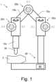
- FIG. 1 shows an exemplary embodiment of a CMM 1 according to the invention.
- the CMM 1 is configured for determining spatial coordinates of measurement points on an object 3. It comprises a structure movably connecting a probe head 30 to a base 40.
- the structure of the CMM 1 comprises three rotary joints 20a, 20b, 20c and three links 10a, 10b, 10c.
- the rotary joints 20a-c movably connect the links 10a-c with each other and with the base 40.
- a first rotary joint 20a provides movability of a first link 10a relative to the base 40 about the two axes of rotation R1 and R2.
- a second rotary joint 20b provides movability of a second link 10b relative to the first link 10a about the axis of rotation R3.
- a third rotary joint 20c provides movability of a third link 10c relative to the second link 10b about the two axes of rotation R4 and R5.
- Each of the joints 20a-c comprises an actuator for moving the connected components relative to another, and a measuring unit with sensors for determining one or more angles between the connected components.
- a control unit 80 of the CMM 1 is configured to receive angular data related to the measured angles from the measuring units, to control the actuators for driving the probe head 30 relative to the base 40 for approaching the measurement point on the object 3, and to determine spatial coordinates of the measurement point based on the angular data.
- the CMM 1 is built light-weight.
- the structure may be built so flexible that that its different distortions due to different poses of the structure alone lead to significant deviations of the probe head 30 from its assumed position so that the measured coordinates may deviate from the real coordinates in such a way that, conventionally, the CMM 1 could not be used for highly-precise measurements.
- the links 10a-c may have a material composition and/or be constructed in a manner that are not considered stable enough, i.e. too flexible, for conventional measurement with a CMM.
- the links 10a-c may be made from light metals, particularly aluminium, light metal alloys, ceramics, plastics and/or carbon-fibre-reinforced polymers.
- Figure 2 illustrates different distortions of the structure of the CMM of Figure 1 due to different poses of its arm-like structure.
- a first pose 50a of the structure (elements shown with dashed lines) the probe head is at a first position 51a.
- the structure assumes a second pose 50b, by changing the angles at each of the rotary joints 20a-c.
- This new pose 50b leads to a different load borne by each of the links.
- this is illustrated for the first link 10a only.
- the new pose 50b leads to a load 60b to be borne by the first link 10a that his higher than the load 60a in the first pose 50a.
- the CMM 1 comprises a functionality to compensate these distortions.
- Figures 3a and 3b show two exemplary embodiments of a joint 20 of a CMM according to the invention.
- a joint 20 movably connects two of the links 10a, 10b.
- one of the joints may movably connect one of the links 10a, 10b with a base of the CMM, and another one of the joints may movably connect another one of the links 10a, 10b with a probe head of the CMM.
- the joint 20 comprises a driving unit 21 having a motor to actuate the two links 10a, 10b that are connected by the joint 20 relative to one another.
- the joint 20 comprises a measuring unit 22 having one or more angular sensors to determine at least one angle between the two links 10a, 10b.
- the measuring unit 21 and the driving unit 22 are provided together, for instance together in a single housing. This allows for a compact setup.
- the measuring unit 21 and the driving unit 22 are provided thermally decoupled from each other, for instance in separate housings. This reduces the heat transfer between the two components, particularly from the motor of the driving unit 22 to the sensors of the measuring unit 21 and the structural elements of the joints. At least one heating element may be is provided at the joint 20 to active control the temperature at the joint, particularly at the measuring unit 22.
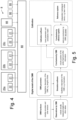
- FIG 4 schematically shows a system 8 for distortion compensation.
- the system 8 comprises the control unit 80 of the CMM of Figure 1 .
- the control unit 80 is configured to receive angular data related to the measured angles from the measuring units 22 of each rotary joint 20a-c and to control the actuators 21 of each rotary joint 20a-c for driving the probe head relative to the base for approaching a measurement point on an object to be measured. Based on the received angular data, spatial coordinates of the probe head (and, thus, the measurement point) can be derived.
- the derived spatial coordinates may differ from the real coordinates in a relevant manner, i.e. to an extent that it negatively influences the measuring precision and provides incorrect values.
- the control unit 80 may have access to distortion information, i.e. information about distortions (or information that enables evaluation of distortions) occurring in the structure under a multitude of different distortion-influencing conditions. This information may be pre-determined and provided in a data base 85. Using this information, the control unit 80 can reconstruct these distortions and then compute the correct coordinates of the probe head and the measurement point.
- further sensors may be connected and provide their data to the control unit 80, e.g. temperature sensors 90 and/or a GNSS sensor 95.
- the distortion-influencing conditions comprise at least a current pose of the structure, i.e. the combination of measured angles between the components.
- each of the links bears a different load and is thus subject to a different distortion (unless the CMM 1 would be used in zero-gravity environments).
- distortion information for a multitude of different poses of the structure need to be provided and accessible by the control unit 80.
- the control unit 80 determines a current pose of the structure based on the angular data received from the measuring units 22, accesses the distortion information for the current pose from the data base 85, determines a current overall distortion based on the distortion information and on the current pose, and determines the spatial coordinate of the measurement point based on the based on the angular data and on the determined distortion of the structure.
- the distortion information may be generated using an archetype of the machine, assuming that each machine that is built with the same components will have the same distortion.
- the distortion information may be generated for each CMM individually.
- the structure is brought sequentially into a multitude of different poses, e.g. hundreds or thousands of poses, wherein for each pose a distortion is determined. This may comprise a target-performance comparison, for instance determining a deviation of the measured coordinates from actual coordinates of a measurement point and setting the difference between these values as the overall distortion. To each of the multitude of poses the overall distortion is assigned.
- each of the multitude of poses, for which an overall distortion is determined may differ from the next poses by increments of 1° about at least one of the axes of rotation R1-R5.
- the overall distortion may be computed, e.g. by extrapolation. Values for extrapolated overall distortion then may be provided in the data base.
- the control unit may be configured to perform the extrapolation.
- the overall distortion may comprise accelerational distortions that are proportional to the second derivative of the pose.
- Accelerational distortions are a result of movements of the structure, i.e. for assuming a certain position in order to measure a certain measurement point. It is possible to wait at the assumed position before measuring the points - and thus to avoid accelerational distortions to influence the measurement of the CMM.
- the distortion information preferably also comprises information relating to accelerational distortions occurring from a multitude of different movements, including an extent of the distortion and a duration of the distortion, e.g. as an increase and decrease of the distortion, in response to the movement.
- the control unit 80 may be configured to consider thermal distortions when calculating an overall distortion.
- the system 8 or the CMM may comprise one or more temperature sensors 90 that generate temperature data which is received by the control unit 80.
- the control unit 80 knows where each of the sensors 90 is positioned, so that an actual temperature distribution within the structure of the CMM may be derived.
- the control unit 80 accesses the distortion information for the current temperature or temperature distribution from the data base 85, and determines the current overall distortion based also on this distortion information and on the current temperature.
- all structural parts in the measurement chain of the machine i.e.
- the structural parts of at least all links 10a-c and all joints 20a-c) have the same or basically the same coefficient of thermal expansion (CTE) along the metrology chain (e.g., all joints have the same axial CTE, whereas the radial CTE is less important).
- CTE coefficient of thermal expansion
- the CTE is within +-30% of variation along the structure (+-3PPM at 10PPM of absolute CTE value of steel), particularly within +-10%.
- the same isotropic material may be used for all structural parts.
- different materials having the same CTE might be used, for instance a stainless steel and a carbon-based composite that is designed to have the same CTE as the used stainless steel.
- gravity is not the same everywhere on earth. For instance, gravity generally increases towards the poles and decreases with height ("normal gravity").
- normal gravity the effect of the poses on the distortion may vary to a degree that negatively effects the accuracy of the compensation.
- the distortion of a CMM located in Alaska may be somewhat different than that of the same CMM located in Singapore.
- gravity anomalies can be found all over the planet; for instance, the composition of the ground at the location of the CMM may influence the value of gravity so that it significantly deviates from normal gravity.
- tidal effects might be considered by calculating the current positions of celestial bodies, particularly Moon and Sun, e.g. based on the location of the CMM and the exact time and date.
- the local value of gravity may be inquired by a user of the CMM and provided to the control unit as a user input, so that the control unit can use it for calculating the overall distortion.
- a location of the CMM may be received as user input or detected by a sensor of the system or CMM, e.g. a GNSS sensor 95. The normal gravity for that location may then be calculated.
- a local value of gravity may be accessed by the control unit, e.g. from its internal data base 85 or via the Internet, e.g. from a data base provided online by the manufacturer of the CMM.
- Figure 5 illustrates the use of a digital model of the CMM for deriving the position of the probe head and a calibration of the digital model using a reference system.
- Encoders and other sensors of the CMM allow observations by the CMM, which includes actually measured angles and optionally also other values.
- Applying a digital model of the CMM may lead to conclusions of the CMM based on its observations, i.e. what we actually want to know, such as the position of the probe head.
- the digital model comprises CMM parameters, i.e. quantitative descriptions of the CMM, e.g. including the lengths of the links, and a simulation software that provides qualitative descriptions of the CMM, i.e. including the kinematics.
- the distortion information of the structure may be provided as part of the digital model, particularly as part of the CMM parameters.
- the simulation of the CMM can be performed with varying level of details depending on the required performance. For instance, the following options can be used:
- Calibration of the CMM to improve the conclusions of the CMM may involve a reference system including an independent metrological device, such as a laser tracker measuring the position of the probe head.
- the conclusions of the reference system i.e. about the probe head's position, are the same as those of the CMM but are considered to be correct. Thus, if there is a deviation between the conclusions of the CMM and the reference system regarding a probe head position, the conclusions of the CMM are considered to be incorrect.
- a calibration software tunes the CMM parameters until the conclusions match, i.e. until the position of the probe head is determined correctly by the CMM. This tuning may include the distortion information.
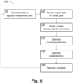
- Figure 6 and 7 show two flow charts illustrating two exemplary embodiments of a method 100 according to the invention for controlling the CMM to determine spatial coordinates of measurement points on an object to be measured.
- the method for instance may be performed by the control unit of the CMM.
- the method 100 comprises controlling 110 motors of rotary joints of the CMM for driving the probe head relative to the base in order to approach a measurement point with the probe head.
- the method further comprises receiving 120 angular data from sensors of the rotary joints.
- the angular data may be received 120 continuously, e.g. during movements of the actuators.
- the received angular data allows determining a current pose of the structure, the pose being defined by the angles.
- the method then continues with receiving 130 pose distortion information, which is provided for a multitude of different poses of the structure, e.g. in a data base of the control unit, and with determining 140 a current pose distortion based on the received angular data (or on a determined pose) and the accessed pose distortion information.
- distortion information about distortions occurring in the components under a multitude of different distortion-influencing conditions (or circumstances) may be accessed, the current pose of the structure being only one of these conditions (or circumstances).
- a current overall distortion of the structure can be determined 150.
- spatial coordinates of the measurement point can be determined 160 based on the angular data and on the current overall distortion of the structure.
- the method 100 may then continue with controlling 110 the actuators to approach the next measurement point, repeating the shown steps until spatial coordinates of all measurement points have been determined 160.
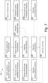
- the method 100 comprises the same steps as in the embodiment of Figure 6 . Additionally, further distortion-influencing conditions are considered for determining the overall distortion.
- the method 100 of Figure 7 thus comprises determining 173 a current acceleration of the structure. Preferably, this includes determining current accelerations for each link of the structure separately. The acceleration may be derived based on the change in the angular data. Alternatively, acceleration sensors may be provided on the structure. Then, acceleration distortion data for the determined acceleration(s) is received 175, e.g. by accessing a database. Based on the acceleration distortion data, a current acceleration distortion is determined 177, and the current overall distortion is determined 150 also based on the current acceleration distortion.
- the further distortion-influencing conditions also comprise a temperature distribution in the structure.
- the method 100 of Figure 7 thus comprises receiving 181 temperature data from one or more temperature sensors and determining 183, based thereon, a current temperature distribution. If the positions of the sensors on the structural elements are known, based on the known pose a 3D distribution of the sensors can be derived. Based on the known 3D distribution of the sensors and on the temperature values each sensor provides, the temperature distribution can be deduced, e.g. including interpolation between sensor positions. Then, thermal distortion data for the determined temperature distribution is received 185, e.g. by accessing a database. Based on the thermal distortion data, a current thermal distortion is determined 187, and the current overall distortion is determined 150 also based on the current thermal distortion.
- the method 100 may further comprise determining 190 a local gravity value, wherein determining the current pose distortion is also based on the local gravity value. Determining 190 the local gravity value may comprise a user input of the respective value. The current pose distortion may then be calculated based on the received distortion data and the gravity value, or distortion data relating to specific combinations of angular data and gravity values may be provided in a data base. Alternatively, only a location of the CMM may be received - e.g. provided through a user input or by means of a GNSS sensor - and the gravity value is determined 190 based on the location. For instance, the normal gravity for that location may be calculated, or a more precise local value of gravity may be accessed from an internal data base or via an Internet connection.
Landscapes
- Physics & Mathematics (AREA)
- General Physics & Mathematics (AREA)
- Length Measuring Devices With Unspecified Measuring Means (AREA)
Abstract
Description
- The present invention generally pertains to a coordinate measuring machine (CMM) and to a method for measuring coordinates with a CMM. More particularly, the invention pertains to a CMM having a functionality for compensating distortions within the machine's structural elements.
- Coordinate measuring devices, such as stationary coordinate measuring machines (CMM) or portable articulated arm coordinate measuring machines (AACMM) or laser-based coordinate measuring devices including laser trackers, laser scanners and total stations are used in a wide variety of applications in quality management and quality assurance. Conventionally, highly precise CMM need to be very stable in order to withstand inertial distortions that may arise due to its own operating weight and - especially since fast measurements are also desirable - its movements. Conventional CMM are thus very heavy devices that are complicated to move and cannot be installed everywhere, e.g. due to weight-loading restrictions.
- It would thus be desirable to provide a light-weight CMM that still allows highly-precise measurements.
- It is therefore an object of the present invention to provide an improved CMM which is less heavy than conventional CMM.
- It is a further object of the present invention to provide such a CMM that allows determining spatial coordinates with high precision.
- It is a further object of the present invention to provide such a CMM that may have light-weight and flexible structural components.
- It is a further object of the present invention to provide such a CMM having a distortion-compensation functionality.
- It is a further object of the present invention to provide such a CMM, wherein the CMM can be portable, handheld and/or battery-operated.
- At least one of these objects is achieved by the CMM of claim 1, the method of claim 11 and/or the dependent claims of the present invention.
- A first aspect of the invention pertains to a CMM for determining at least one spatial coordinate of a measurement point on an object, the CMM comprising a structure movably connecting a probe head to a base, the structure comprising a plurality of rotary joints and a plurality of elongate components, the components comprising a plurality of links. At least one of the rotary joints movably connects two of the components with each other, comprises a driving unit comprising a motor to actuate the connected components relative to another, and comprises a measuring unit comprising one or more sensors to determine at least one angle between the connected components and to generate angular data. The CMM comprises a control unit configured to control the motor of each driving unit for driving the probe head relative to the base for approaching the measurement point, to receive the angular data, and to determine the at least one spatial coordinate of the measurement point based on the angular data. The control unit has access to distortion information about distortions occurring in the components and/or joints under a multitude of different distortion-influencing conditions of the structure.
- According to some embodiments of the CMM, these conditions comprise at least a current pose of the structure that is defined by the angles between the components, the distortion information comprising pose distortion information for a multitude of different poses of the structure. In these embodiments, the control unit is configured
- to receive pose distortion information for the current pose,
- to determine a current pose distortion based on the pose distortion information for the current pose, the pose distortion being a distortion of the structure due to its pose,
- to determine a current overall distortion of the structure based at least on the current pose distortion, and
- to determine the at least one spatial coordinate also based on the current overall distortion of the structure.
- According to some embodiments of the CMM, the conditions comprise at least one or more current accelerations of the structure that are a consequence of a motorized movement of the components, wherein the distortion information comprises acceleration distortion information for a multitude of different movements of the structure. In these embodiments, the control unit is configured
- to determine a current acceleration of the structure, particularly based on the angular data,
- to determine a current acceleration distortion based on the acceleration distortion information and on the current acceleration, and
- to determine the current overall distortion of the structure based also on the current acceleration distortion.
- According to some embodiments of the CMM, the conditions comprise at least a current temperature distribution in the structure, wherein the distortion information comprises thermal distortion information for a multitude of different temperature distributions in the structure. In these embodiments, the control unit is configured
- to receive temperature data,
- to determine a current temperature distribution of the structure based on the temperature data,
- to determine a current thermal distortion based on the thermal distortion information and on the current temperature distribution, and
- to determine the current overall distortion of the structure based also on the current thermal distortion.
- For instance, one or more temperature sensors may be provided at each link or at each component, the temperature data being generated by these temperature sensors.
- According to some embodiments of the CMM, the amount of pose distortion is at least partly a consequence of gravity, wherein the distortion information comprises the pose distortion information for a multitude of different poses of the structure under the influence of a multitude of different gravitational values. In these embodiments, the control unit is configured
- to determine a gravitational value for a current (e.g. geographic) location of the coordinate measuring machine, and
- to determine the current pose distortion based also on the gravitational value.
- For instance, the control unit may be configured to receive position data related to a location of the CMM and to determine the current location of the CMM based on the position data. The location in particular may be a geographic location, e.g. comprising longitude and latitude values as well as a height.
- In some embodiments of the CMM, the distortion information relates to distortions occurring in each of the links.
- In some embodiments of the CMM, the elongate components further comprise the base and/or the probe head.
- According to some embodiments of the CMM,
- at least a subset of the components, particularly at least a subset of the links, comprises supporting elements that are made from a first material or material composition,
- at least a subset of the rotary joints comprises supporting elements that are made from a second material or material composition, and
- the first material or material composition is more flexible than the second material or material composition.
- Optionally, the first material or material composition has a lower overall density than the second material or material composition.
- The first material composition for instance may comprise aluminium or other light metals, light metal alloys, ceramics, plastics and/or carbon-fibre-reinforced polymers. The second material or material composition for instance may comprise high-alloy steel or a comparable material, e.g. coated low-alloy steel. The second material should provide a uniform coefficient of thermal expansion (CTE) along the whole metrology chain (which includes bearings and sensor interfaces) and a high Young modulus for high stiffness with low form factor.
- In some embodiments of the CMM, the measuring unit and the driving unit of each rotary joint are thermally decoupled from each other and/or are provided in separate housings.
- In some embodiments of the CMM, at least one rotary joint comprises a measuring unit that includes at least two rotary encoders as angular sensors, each rotary encoder being configured to determine a relative pose between a first link and a second link with at least three degrees of freedom.
- In some embodiments of the CMM, at least one measuring unit is configured to determine relative poses between two links in at least five degrees of freedom.
- In some embodiments of the CMM, the distortion information is provided as part of a digital model of the CMM.
- A second aspect of the invention pertains to a computer-implemented method for controlling a CMM - e.g. the coordinate measuring machine according to the first aspect of the invention - to determine at least one spatial coordinate of a measurement point on an object to be measured, wherein the CMM comprises a structure movably connecting a probe head to a base, the structure comprising a plurality of rotary joints and a plurality of elongate components, the components comprising a plurality of links, each rotary joint movably connecting two of the components with each other, comprising a driving unit with a motor to actuate the connected components relative to another, and a measuring unit with one or more angular sensors to measure at least one angle between the connected components and to generate angular data.
- The method, which may be performed by a control unit of the CMM, comprises controlling the motors for driving the probe head relative to the base for approaching the measurement point, and receiving the angular data.
- The method further comprises
- receiving distortion information about distortions occurring in the components under a multitude of different distortion-influencing conditions,
- determining a current overall distortion of the structure, and
- determining the at least one spatial coordinate of the measurement point based on the angular data and on the determined current overall distortion.
- According to some embodiments of the method, the conditions comprise at least a current pose of the structure that is defined by the angles between the links, the distortion information comprising pose distortion information for a multitude of different poses of the structure. In these embodiments, the method comprises determining a current pose distortion based on the pose distortion information and on the angular data. Determining the current overall distortion of the structure is then based at least on the current pose distortion.
- According to some embodiments of the method, the conditions comprise at least current accelerations of the structure that are a consequence of a motorized movement of the components, wherein the distortion information comprises acceleration distortion information for a multitude of different movements of the structure. In these embodiments, the method comprises determining a current movement or acceleration of the structure, particularly based on the angular data, and determining a current acceleration distortion based on the acceleration distortion information and on the current movement. Determining the current overall distortion of the structure is then based at least on the current acceleration distortion.
- According to some embodiments of the method, the conditions comprise at least a current temperature distribution in the structure, wherein the distortion information comprises thermal distortion information for a multitude of different temperature distributions in the structure. In these embodiments, the method comprises receiving temperature data, determining a current temperature distribution of the structure based on the temperature data, and determining a current thermal distortion based on the thermal distortion information and on the current temperature distribution. Determining the current overall distortion of the structure is then based at least on the current thermal distribution.
- According to some embodiments of the method, the amount of pose distortion is at least partly a consequence of gravity, wherein the distortion information comprises the pose distortion information for a multitude of different poses of the structure under the influence of a multitude of different gravitational values. In these embodiments, the method comprises receiving position data related to a location of the coordinate measuring machine, determining a current location of the coordinate measuring machine based on the position data, and determining a gravitational value for the current location. Determining the current pose distortion is then also based on the gravitational value for the current location.
- A third aspect of the invention pertains to a computer program product comprising program code which is stored on a machine-readable medium, or being embodied by an electromagnetic wave comprising a program code segment, and having computer-executable instructions for performing the method according to the second aspect of the invention, particularly when executed in a control unit of a CMM according to the first aspect of the invention.
- The invention in the following will be described in detail by referring to exemplary embodiments that are accompanied by figures, in which:
- Fig. 1
- shows an exemplary embodiment of a CMM according to the invention;
- Fig. 2
- shows the CMM assuming two different poses;
- Figs. 3a-b
- show two exemplary embodiments of a joint as part of a CMM according to the invention;
- Fig. 4
- shows an exemplary embodiment of a system for compensating distortions;
- Fig. 5
- illustrates using and calibrating a digital model of the CMM;
- Fig. 6
- shows a flowchart illustrating a first exemplary embodiment of a method according to the invention; and
- Fig. 7
- shows a flowchart illustrating a second exemplary embodiment of a method according to the invention.
-
Figure 1 shows an exemplary embodiment of a CMM 1 according to the invention. The CMM 1 is configured for determining spatial coordinates of measurement points on anobject 3. It comprises a structure movably connecting aprobe head 30 to abase 40. - In the shown example, the structure of the CMM 1 comprises three
rotary joints links links 10a-c with each other and with thebase 40. A first rotary joint 20a provides movability of afirst link 10a relative to the base 40 about the two axes of rotation R1 and R2. A second rotary joint 20b provides movability of asecond link 10b relative to thefirst link 10a about the axis of rotation R3. A third rotary joint 20c provides movability of athird link 10c relative to thesecond link 10b about the two axes of rotation R4 and R5. - Each of the
joints 20a-c comprises an actuator for moving the connected components relative to another, and a measuring unit with sensors for determining one or more angles between the connected components. Acontrol unit 80 of the CMM 1 is configured to receive angular data related to the measured angles from the measuring units, to control the actuators for driving theprobe head 30 relative to thebase 40 for approaching the measurement point on theobject 3, and to determine spatial coordinates of the measurement point based on the angular data. - The CMM 1 is built light-weight. To save weight, the structure may be built so flexible that that its different distortions due to different poses of the structure alone lead to significant deviations of the
probe head 30 from its assumed position so that the measured coordinates may deviate from the real coordinates in such a way that, conventionally, the CMM 1 could not be used for highly-precise measurements. Especially thelinks 10a-c may have a material composition and/or be constructed in a manner that are not considered stable enough, i.e. too flexible, for conventional measurement with a CMM. For instance, thelinks 10a-c may be made from light metals, particularly aluminium, light metal alloys, ceramics, plastics and/or carbon-fibre-reinforced polymers. -
Figure 2 illustrates different distortions of the structure of the CMM ofFigure 1 due to different poses of its arm-like structure. In a first pose 50a of the structure (elements shown with dashed lines) the probe head is at afirst position 51a. For amovement 70 of the probe head to a second position 51b, the structure assumes a second pose 50b, by changing the angles at each of therotary joints 20a-c. This new pose 50b leads to a different load borne by each of the links. Here, this is illustrated for thefirst link 10a only. The new pose 50b leads to aload 60b to be borne by thefirst link 10a that his higher than theload 60a in the first pose 50a. This effects adistortion 61 in thefirst link 10a that differs from the previous distortion during the first pose 50a. Due to these distortions, thereal positions 51a, 51b of the probe head differs from the assumedpositions real position 51a and the assumedposition 52a in the first pose 50a is smaller than the difference between the real position 51b and the assumedposition 52b in the second pose 50b. To overcome this lack of precision due toinertial distortions 61, according to the invention the CMM 1 comprises a functionality to compensate these distortions. -
Figures 3a and 3b show two exemplary embodiments of a joint 20 of a CMM according to the invention. As shown here, a joint 20 movably connects two of thelinks links links Figures 3a and 3b , the joint 20 comprises a drivingunit 21 having a motor to actuate the twolinks unit 22 having one or more angular sensors to determine at least one angle between the twolinks - In the example of
Figure 3a , the measuringunit 21 and the drivingunit 22 are provided together, for instance together in a single housing. This allows for a compact setup. - In the example of
Figure 3b , the measuringunit 21 and the drivingunit 22 are provided thermally decoupled from each other, for instance in separate housings. This reduces the heat transfer between the two components, particularly from the motor of the drivingunit 22 to the sensors of the measuringunit 21 and the structural elements of the joints. At least one heating element may be is provided at the joint 20 to active control the temperature at the joint, particularly at the measuringunit 22. -
Figure 4 schematically shows asystem 8 for distortion compensation. In the shown example, thesystem 8 comprises thecontrol unit 80 of the CMM ofFigure 1 . Thecontrol unit 80 is configured to receive angular data related to the measured angles from the measuringunits 22 of each rotary joint 20a-c and to control theactuators 21 of each rotary joint 20a-c for driving the probe head relative to the base for approaching a measurement point on an object to be measured. Based on the received angular data, spatial coordinates of the probe head (and, thus, the measurement point) can be derived. However, due to distortions occurring in the structure - for instance dependent on a current pose of the structure -, the derived spatial coordinates may differ from the real coordinates in a relevant manner, i.e. to an extent that it negatively influences the measuring precision and provides incorrect values. - Thus, according to the invention, the
control unit 80 may have access to distortion information, i.e. information about distortions (or information that enables evaluation of distortions) occurring in the structure under a multitude of different distortion-influencing conditions. This information may be pre-determined and provided in adata base 85. Using this information, thecontrol unit 80 can reconstruct these distortions and then compute the correct coordinates of the probe head and the measurement point. Optionally, further sensors may be connected and provide their data to thecontrol unit 80,e.g. temperature sensors 90 and/or aGNSS sensor 95. - The distortion-influencing conditions comprise at least a current pose of the structure, i.e. the combination of measured angles between the components. In every pose of the structure, each of the links bears a different load and is thus subject to a different distortion (unless the CMM 1 would be used in zero-gravity environments). Thus, distortion information for a multitude of different poses of the structure need to be provided and accessible by the
control unit 80. Thecontrol unit 80 then determines a current pose of the structure based on the angular data received from the measuringunits 22, accesses the distortion information for the current pose from thedata base 85, determines a current overall distortion based on the distortion information and on the current pose, and determines the spatial coordinate of the measurement point based on the based on the angular data and on the determined distortion of the structure. - The distortion information may be generated using an archetype of the machine, assuming that each machine that is built with the same components will have the same distortion. Alternatively, the distortion information may be generated for each CMM individually. For generating the distortion information, the structure is brought sequentially into a multitude of different poses, e.g. hundreds or thousands of poses, wherein for each pose a distortion is determined. This may comprise a target-performance comparison, for instance determining a deviation of the measured coordinates from actual coordinates of a measurement point and setting the difference between these values as the overall distortion. To each of the multitude of poses the overall distortion is assigned.
- For instance, each of the multitude of poses, for which an overall distortion is determined, may differ from the next poses by increments of 1° about at least one of the axes of rotation R1-R5. For values in-between the increments, the overall distortion may be computed, e.g. by extrapolation. Values for extrapolated overall distortion then may be provided in the data base. Alternatively, the control unit may be configured to perform the extrapolation.
- Additionally, the overall distortion may comprise accelerational distortions that are proportional to the second derivative of the pose. Accelerational distortions are a result of movements of the structure, i.e. for assuming a certain position in order to measure a certain measurement point. It is possible to wait at the assumed position before measuring the points - and thus to avoid accelerational distortions to influence the measurement of the CMM. However, it would be advantageous to increase the measurements by not having to wait. Therefore, the distortion information preferably also comprises information relating to accelerational distortions occurring from a multitude of different movements, including an extent of the distortion and a duration of the distortion, e.g. as an increase and decrease of the distortion, in response to the movement.
- Distortion generally also depends on a temperature of the structural elements. Therefore, optionally, the
control unit 80 may be configured to consider thermal distortions when calculating an overall distortion. Thesystem 8 or the CMM may comprise one ormore temperature sensors 90 that generate temperature data which is received by thecontrol unit 80. Optionally, especially if there are more than one temperature sensors, thecontrol unit 80 knows where each of thesensors 90 is positioned, so that an actual temperature distribution within the structure of the CMM may be derived. Thecontrol unit 80 accesses the distortion information for the current temperature or temperature distribution from thedata base 85, and determines the current overall distortion based also on this distortion information and on the current temperature. To further improve the thermal behavior of the CMM, preferably all structural parts in the measurement chain of the machine (i.e. structural parts of at least alllinks 10a-c and alljoints 20a-c) have the same or basically the same coefficient of thermal expansion (CTE) along the metrology chain (e.g., all joints have the same axial CTE, whereas the radial CTE is less important). Preferably, the CTE is within +-30% of variation along the structure (+-3PPM at 10PPM of absolute CTE value of steel), particularly within +-10%. To achieve the uniform CTE, the same isotropic material may be used for all structural parts. Alternatively, different materials having the same CTE might be used, for instance a stainless steel and a carbon-based composite that is designed to have the same CTE as the used stainless steel. - Moreover, gravity is not the same everywhere on earth. For instance, gravity generally increases towards the poles and decreases with height ("normal gravity"). Thus, the effect of the poses on the distortion may vary to a degree that negatively effects the accuracy of the compensation. For instance, depending on the pose, the distortion of a CMM located in Alaska may be somewhat different than that of the same CMM located in Singapore. Also, gravity anomalies can be found all over the planet; for instance, the composition of the ground at the location of the CMM may influence the value of gravity so that it significantly deviates from normal gravity. For extremely precise applications also tidal effects might be considered by calculating the current positions of celestial bodies, particularly Moon and Sun, e.g. based on the location of the CMM and the exact time and date.
- The local value of gravity may be inquired by a user of the CMM and provided to the control unit as a user input, so that the control unit can use it for calculating the overall distortion. Alternatively, a location of the CMM may be received as user input or detected by a sensor of the system or CMM, e.g. a
GNSS sensor 95. The normal gravity for that location may then be calculated. Also, a local value of gravity may be accessed by the control unit, e.g. from itsinternal data base 85 or via the Internet, e.g. from a data base provided online by the manufacturer of the CMM. -
Figure 5 illustrates the use of a digital model of the CMM for deriving the position of the probe head and a calibration of the digital model using a reference system. Encoders and other sensors of the CMM allow observations by the CMM, which includes actually measured angles and optionally also other values. Applying a digital model of the CMM may lead to conclusions of the CMM based on its observations, i.e. what we actually want to know, such as the position of the probe head. The digital model comprises CMM parameters, i.e. quantitative descriptions of the CMM, e.g. including the lengths of the links, and a simulation software that provides qualitative descriptions of the CMM, i.e. including the kinematics. The distortion information of the structure may be provided as part of the digital model, particularly as part of the CMM parameters. - The simulation of the CMM can be performed with varying level of details depending on the required performance. For instance, the following options can be used:
- 1. Rigid model: An ordinary rigid-body model with a single degree of freedom per joint. Since it is too inaccurate for most metrology applications, it may be used predominantly for motion control.
- 2. Static elastic model: This model has multiple degrees of freedom per joint to compensate for unwanted displacements. Additionally, it compensates the bending of the machine under the force of gravity. It can be used for slow-movement metrology.
- 3. Dynamic elastic model: This model additionally compensates the bending of the machine under inertial forces. It can be used for fast-movement metrology.
- 4. Indeterministic correlative model: This model compensates any effect that correlates with measured signals, however requiring huge amounts of calibration data.
- Calibration of the CMM to improve the conclusions of the CMM may involve a reference system including an independent metrological device, such as a laser tracker measuring the position of the probe head. The conclusions of the reference system, i.e. about the probe head's position, are the same as those of the CMM but are considered to be correct. Thus, if there is a deviation between the conclusions of the CMM and the reference system regarding a probe head position, the conclusions of the CMM are considered to be incorrect. A calibration software tunes the CMM parameters until the conclusions match, i.e. until the position of the probe head is determined correctly by the CMM. This tuning may include the distortion information.
-
Figure 6 and7 show two flow charts illustrating two exemplary embodiments of amethod 100 according to the invention for controlling the CMM to determine spatial coordinates of measurement points on an object to be measured. The method for instance may be performed by the control unit of the CMM. Themethod 100 comprises controlling 110 motors of rotary joints of the CMM for driving the probe head relative to the base in order to approach a measurement point with the probe head. The method further comprises receiving 120 angular data from sensors of the rotary joints. The angular data may be received 120 continuously, e.g. during movements of the actuators. The received angular data allows determining a current pose of the structure, the pose being defined by the angles. - In the embodiment shown in
Figure 6 , the method then continues with receiving 130 pose distortion information, which is provided for a multitude of different poses of the structure, e.g. in a data base of the control unit, and with determining 140 a current pose distortion based on the received angular data (or on a determined pose) and the accessed pose distortion information. Optionally (not shown here), distortion information about distortions occurring in the components under a multitude of different distortion-influencing conditions (or circumstances) may be accessed, the current pose of the structure being only one of these conditions (or circumstances). - Based at least on the current pose distortion - and optionally distortions from other distortion-influencing conditions - a current overall distortion of the structure can be determined 150. Finally, spatial coordinates of the measurement point can be determined 160 based on the angular data and on the current overall distortion of the structure.
- The
method 100 may then continue with controlling 110 the actuators to approach the next measurement point, repeating the shown steps until spatial coordinates of all measurement points have been determined 160. - In the embodiment shown in
Figure 7 , themethod 100 comprises the same steps as in the embodiment ofFigure 6 . Additionally, further distortion-influencing conditions are considered for determining the overall distortion. - These further distortion-influencing conditions comprise a current acceleration of the structure, for instance due to the movements of the structure to approach a measurement point. Controlling 110 these movements may be based on continuously received 120 angular data. If the distortion due to acceleration is not considered during these movements, the probe head is at the wrong position until the acceleration is stopped and the acceleration distortion returns to "normal". Thus, in order to prevent providing wrong coordinates, it is necessary to stop the movement for some time at every measurement point, thereby slowing down the measuring process. The
method 100 ofFigure 7 thus comprises determining 173 a current acceleration of the structure. Preferably, this includes determining current accelerations for each link of the structure separately. The acceleration may be derived based on the change in the angular data. Alternatively, acceleration sensors may be provided on the structure. Then, acceleration distortion data for the determined acceleration(s) is received 175, e.g. by accessing a database. Based on the acceleration distortion data, a current acceleration distortion is determined 177, and the current overall distortion is determined 150 also based on the current acceleration distortion. - The further distortion-influencing conditions also comprise a temperature distribution in the structure. Depending on the used materials, temperature changes may lead to relevant distortions in the structure. The
method 100 ofFigure 7 thus comprises receiving 181 temperature data from one or more temperature sensors and determining 183, based thereon, a current temperature distribution. If the positions of the sensors on the structural elements are known, based on the known pose a 3D distribution of the sensors can be derived. Based on the known 3D distribution of the sensors and on the temperature values each sensor provides, the temperature distribution can be deduced, e.g. including interpolation between sensor positions. Then, thermal distortion data for the determined temperature distribution is received 185, e.g. by accessing a database. Based on the thermal distortion data, a current thermal distortion is determined 187, and the current overall distortion is determined 150 also based on the current thermal distortion. - The
method 100 may further comprise determining 190 a local gravity value, wherein determining the current pose distortion is also based on the local gravity value. Determining 190 the local gravity value may comprise a user input of the respective value. The current pose distortion may then be calculated based on the received distortion data and the gravity value, or distortion data relating to specific combinations of angular data and gravity values may be provided in a data base. Alternatively, only a location of the CMM may be received - e.g. provided through a user input or by means of a GNSS sensor - and the gravity value is determined 190 based on the location. For instance, the normal gravity for that location may be calculated, or a more precise local value of gravity may be accessed from an internal data base or via an Internet connection. - Although the invention is illustrated above, partly with reference to some preferred embodiments, it must be understood that numerous modifications and combinations of different features of the embodiments can be made. All of these modifications lie within the scope of the appended claims.
Claims (15)
- Coordinate measuring machine (1) for determining at least one spatial coordinate of a measurement point on an object (3), the coordinate measuring machine (1) comprising a structure movably connecting a probe head (30) to a base (40), the structure comprising a plurality of rotary joints (20a-c) and a plurality of elongate components, the components comprising a plurality of links (10a-c), wherein at least one rotary joint- movably connects two of the components with each other,- comprises a driving unit (21) comprising a motor to actuate the connected components relative to another, and- comprises a measuring unit (22) comprising one or more sensors to determine at least one angle between the connected components and to generate angular data,wherein the coordinate measuring machine (1) comprises a control unit (80) configured- to control (110) the motor of each driving unit (21) for driving the probe head (30) relative to the base (40) for approaching the measurement point,- to receive (120) the angular data, and- to determine the at least one spatial coordinate of the measurement point based on the angular data,characterized in that
the control unit (80) has access to distortion information about distortions occurring in the components and/or joints under a multitude of different distortion-influencing conditions of the structure, wherein the conditions comprise at least a current pose (50a-b) of the structure that is defined by the angles between the components, the distortion information comprising pose distortion information for a multitude of different poses (50a-b) of the structure, the control unit (80) being configured- to receive (130) pose distortion information for the current pose (50a-b),- to determine (140) a current pose distortion based on the pose distortion information for the current pose (50a-b), the pose distortion being a distortion of the structure due to the pose (50a-b),- to determine (150) a current overall distortion of the structure based at least on the current pose distortion, and- to determine (160) the at least one spatial coordinate also based on the current overall distortion of the structure. - Coordinate measuring machine (1) according to claim 1, wherein the conditions comprise at least one or more current accelerations of the structure that are a consequence of a motorized movement of the components, wherein the distortion information comprises acceleration distortion information for a multitude of different movements (70) of the structure, the control unit being configured- to determine (173) a current acceleration of the structure, particularly based on the angular data,- to determine (177) a current acceleration distortion based on the acceleration distortion information and on the current acceleration, and- to determine (150) the current overall distortion of the structure based also on the current acceleration distortion.
- Coordinate measuring machine (1) according to claim 1 or claim 2, wherein the conditions comprise at least a current temperature distribution in the structure, wherein the distortion information comprises thermal distortion information for a multitude of different temperature distributions in the structure, the control unit being configured- to receive (181) temperature data,- to determine (183) a current temperature distribution of the structure based on the temperature data,- to determine (187) a current thermal distortion based on the thermal distortion information and on the current temperature distribution, and- to determine (150) the current overall distortion of the structure based also on the current thermal distortion,particularly wherein one or more temperature sensors are provided at each link or at each component, the temperature data being generated by the temperature sensors.
- Coordinate measuring machine (1) according to any one of the preceding claims, wherein the amount of pose distortion is at least partly a consequence of gravity, wherein the distortion information comprises the pose distortion information for a multitude of different poses of the structure under the influence of a multitude of different gravitational values, the control unit being configured- to determine (190) a gravitational value for a current location of the coordinate measuring machine (1), particularly for a current geographic location, and- to determine (140) the current pose distortion based also on the gravitational value,particularly wherein the control unit is configured to receive position data related to a location of the coordinate measuring machine (1) and to determine the current location of the coordinate measuring machine (1) based on the position data.
- Coordinate measuring machine (1) according to any one of the preceding claims, wherein- the distortion information relates to distortions occurring in each of the links (10a-c), and/or- the elongate components further comprise the base (40) and/or the probe head (30).
- Coordinate measuring machine (1) according to any one of the preceding claims, wherein- at least a subset of the components, particularly at least a subset of the links (10a-c), comprises supporting elements that are made from a first material or material composition,- at least a subset of the rotary joints (20a-c) comprises supporting elements that are made from a second material or material composition, and- the first material or material composition is more flexible than the second material or material composition,particularly wherein- the first material or material composition has a lower overall density than the second material or material composition;- the first material composition comprises light metals, particularly aluminium, light metal alloys, ceramics, plastics and/or carbon-fibre-reinforced polymers; and/or- the second material or material composition comprises steel, particularly high-alloy steel.
- Coordinate measuring machine (1) according to any one of the preceding claims, wherein the measuring unit (22) and the driving unit (21) of each rotary joint (20a-c) are thermally decoupled from each other and/or are provided in separate housings.
- Coordinate measuring machine (1) according to any one of the preceding claims, wherein at least one rotary joint (20a-c) comprises a measuring unit (22) that includes at least two rotary encoders as angular sensors, each rotary encoder being configured to determine a relative pose between a first link and a second link with at least three degrees of freedom.
- Coordinate measuring machine (1) according to any one of the preceding claims, wherein at least one measuring unit (22) is configured to determine relative poses between two links (10a-c) in at least five degrees of freedom.
- Coordinate measuring machine (1) according to any one of the preceding claims, wherein the distortion information is provided as part of a digital model of the coordinate measuring machine (1).
- Computer-implemented method (100) for controlling a coordinate measuring machine (1), particularly a coordinate measuring machine according to any one of the preceding claims, to determine at least one spatial coordinate of a measurement point on an object (3) to be measured, wherein the coordinate measuring machine (1) comprises a structure movably connecting a probe head (30) to a base (40), the structure comprising a plurality of rotary joints (20a-c) and a plurality of elongate components, the components comprising a plurality of links (10a-c), each rotary joint (20a-c)- movably connecting two of the components with each other,- comprising a driving unit (21) with a motor to actuate the connected components relative to another, and- a measuring unit (22) with one or more angular sensors to measure at least one angle between the connected components and to generate angular data,the method (100) comprising controlling (110) the motors for driving the probe head (30) relative to the base for approaching the measurement point, and receiving (120) the angular data,
characterized by- receiving (130, 175, 185) distortion information about distortions occurring in the components under a multitude of different distortion-influencing conditions, wherein the conditions comprise at least a current pose (50a-b) of the structure that is defined by the angles between the links, the distortion information comprising pose distortion information for a multitude of different poses (50a-b) of the structure,- determining (140) a current pose distortion based on the pose distortion information and on the angular data,- determining (150) a current overall distortion of the structure based at least on the current pose distortion, and- determining (160) the at least one spatial coordinate of the measurement point based on the angular data and on the determined current overall distortion. - Method (100) according to claim 11, wherein the conditions comprise at least current accelerations of the structure that are a consequence of a motorized movement (70) of the components, wherein the distortion information comprises acceleration distortion information for a multitude of different movements of the structure, the method comprising- determining (173) a current movement or acceleration of the structure, particularly based on the angular data, and- determining (177) a current acceleration distortion based on the acceleration distortion information and on the current movement,wherein determining (150) the current overall distortion of the structure is also based on the current acceleration distortion.
- Method (100) according to claim 11 or claim 12, wherein the conditions comprise at least a current temperature distribution in the structure, wherein the distortion information comprises thermal distortion information for a multitude of different temperature distributions in the structure, the method comprising- receiving (181) temperature data,- determining (183) a current temperature distribution of the structure based on the temperature data, and- determining (187) a current thermal distortion based on the thermal distortion information and on the current temperature distribution,wherein determining (150) the current overall distortion of the structure is also based on the current thermal distribution.
- Method (100) according to any one of claims 11 to 13, wherein the amount of pose distortion is at least partly a consequence of gravity, wherein the distortion information comprises the pose distortion information for a multitude of different poses (50a-b) of the structure under the influence of a multitude of different gravitational values, the method comprising- receiving position data related to a location of the coordinate measuring machine (1), particularly a geographic location,- determining a current location of the coordinate measuring machine (1) based on the position data, and- determining (190) a gravitational value for the current location,wherein determining (140) the current pose distortion is also based on the gravitational value for the current location.
- Computer programme product comprising programme code which is stored on a machine-readable medium, or being embodied by an electromagnetic wave comprising a programme code segment, and having computer-executable instructions for performing, particularly when executed in a control unit of a coordinate measuring machine according to any one of claims 1 to 10, the method according to any one of claims 11 to 14.
Priority Applications (3)
| Application Number | Priority Date | Filing Date | Title |
|---|---|---|---|
| EP22215431.2A EP4390305B1 (en) | 2022-12-21 | 2022-12-21 | Coordinate measuring machine |
| US18/525,552 US20240210154A1 (en) | 2022-12-21 | 2023-11-30 | Coordinate measuring machine |
| CN202311725969.0A CN118225016A (en) | 2022-12-21 | 2023-12-14 | Coordinate measuring machine |
Applications Claiming Priority (1)
| Application Number | Priority Date | Filing Date | Title |
|---|---|---|---|
| EP22215431.2A EP4390305B1 (en) | 2022-12-21 | 2022-12-21 | Coordinate measuring machine |
Publications (2)
| Publication Number | Publication Date |
|---|---|
| EP4390305A1 true EP4390305A1 (en) | 2024-06-26 |
| EP4390305B1 EP4390305B1 (en) | 2025-03-26 |
Family
ID=84569212
Family Applications (1)
| Application Number | Title | Priority Date | Filing Date |
|---|---|---|---|
| EP22215431.2A Active EP4390305B1 (en) | 2022-12-21 | 2022-12-21 | Coordinate measuring machine |
Country Status (3)
| Country | Link |
|---|---|
| US (1) | US20240210154A1 (en) |
| EP (1) | EP4390305B1 (en) |
| CN (1) | CN118225016A (en) |
Cited By (2)
| Publication number | Priority date | Publication date | Assignee | Title |
|---|---|---|---|---|
| EP4682462A1 (en) * | 2024-07-16 | 2026-01-21 | Hexagon Innovation Hub GmbH | Measurement accuracy perception and user guiding for manually driven articulated arm coordinate measuring machine |
| US12613087B2 (en) | 2023-01-25 | 2026-04-28 | Hexagon Innovation Hub Gmbh | Coordinate measuring machine |
Citations (2)
| Publication number | Priority date | Publication date | Assignee | Title |
|---|---|---|---|---|
| US20190066337A1 (en) * | 2017-08-29 | 2019-02-28 | Faro Technologies, Inc. | Articulated arm coordinate measuring machine having a color laser line probe |
| DE102019220247A1 (en) * | 2019-12-19 | 2021-06-24 | Carl Zeiss Industrielle Messtechnik Gmbh | Method and arrangement for the optical calibration of axes of rotation for coordinate measurements |
Family Cites Families (1)
| Publication number | Priority date | Publication date | Assignee | Title |
|---|---|---|---|---|
| US9110456B2 (en) * | 2004-09-08 | 2015-08-18 | Abb Research Ltd. | Robotic machining with a flexible manipulator |
-
2022
- 2022-12-21 EP EP22215431.2A patent/EP4390305B1/en active Active
-
2023
- 2023-11-30 US US18/525,552 patent/US20240210154A1/en active Pending
- 2023-12-14 CN CN202311725969.0A patent/CN118225016A/en active Pending
Patent Citations (2)
| Publication number | Priority date | Publication date | Assignee | Title |
|---|---|---|---|---|
| US20190066337A1 (en) * | 2017-08-29 | 2019-02-28 | Faro Technologies, Inc. | Articulated arm coordinate measuring machine having a color laser line probe |
| DE102019220247A1 (en) * | 2019-12-19 | 2021-06-24 | Carl Zeiss Industrielle Messtechnik Gmbh | Method and arrangement for the optical calibration of axes of rotation for coordinate measurements |
Cited By (2)
| Publication number | Priority date | Publication date | Assignee | Title |
|---|---|---|---|---|
| US12613087B2 (en) | 2023-01-25 | 2026-04-28 | Hexagon Innovation Hub Gmbh | Coordinate measuring machine |
| EP4682462A1 (en) * | 2024-07-16 | 2026-01-21 | Hexagon Innovation Hub GmbH | Measurement accuracy perception and user guiding for manually driven articulated arm coordinate measuring machine |
Also Published As
| Publication number | Publication date |
|---|---|
| EP4390305B1 (en) | 2025-03-26 |
| US20240210154A1 (en) | 2024-06-27 |
| CN118225016A (en) | 2024-06-21 |
Similar Documents
| Publication | Publication Date | Title |
|---|---|---|
| US20240210154A1 (en) | Coordinate measuring machine | |
| Whitney et al. | Industrial robot forward calibration method and results | |
| Renders et al. | Kinematic calibration and geometrical parameter identification for robots. | |
| US8219353B2 (en) | Absolute diameter measurement arm | |
| CN100504687C (en) | System and method for measuring, compensating and testing numerically controlled machine tool heads and/or tables | |
| JP5618066B2 (en) | Force control robot calibration apparatus and method | |
| Li et al. | A dynamic pre-travel error prediction model for the kinematic touch trigger probe | |
| US9157723B2 (en) | Absolute diameter measurement arm | |
| Dichev et al. | Automated system for calibrating instruments measuring parameters of moving objects | |
| CN118938806B (en) | Driving force optimization method for large aircraft component assembly based on force-position coordinated measurement | |
| Jeong et al. | Thermally induced error compensation of 5-axis machine tools in the environment with temperature fluctuation | |
| CN121113404A (en) | A method for measuring the stiffness of robot servo joints | |
| Chai et al. | A practical calibration process using partial information for a commercial Stewart platform | |
| JP2018511046A (en) | Calibration of dimension measuring equipment | |
| Warnecke et al. | Assessment of industrial robots | |
| Fan et al. | Design analysis and applications of a 3D laser ball bar for accuracy calibration of multiaxis machines | |
| CN119362959A (en) | Torque coefficient correction method for servo motor of robot joint | |
| Putz et al. | Implementation and demonstration of characteristic diagram as well as structure model based correction of thermo-elastic tool center point displacements | |
| Trevisani | Feedback control of flexible four-bar linkages: a numerical and experimental investigation | |
| TWI444798B (en) | Multi - degree of freedom platform control device | |
| English et al. | Kinematic calibration of six-axis robots | |
| Eisentraeger et al. | Verification of the active deformation compensation system of the LMT/GTM by end-to-end simulations | |
| Longstaff et al. | Calibration and correction methods of spatial errors found in Cartesian manipulators | |
| Song et al. | Calibration method of articulated arm coordinate measuring machine based on virtual calibrators | |
| Ren et al. | Kinematic calibration of parallel robots using orientation constraint |
Legal Events
| Date | Code | Title | Description |
|---|---|---|---|
| PUAI | Public reference made under article 153(3) epc to a published international application that has entered the european phase |
Free format text: ORIGINAL CODE: 0009012 |
|
| STAA | Information on the status of an ep patent application or granted ep patent |
Free format text: STATUS: THE APPLICATION HAS BEEN PUBLISHED |
|
| AK | Designated contracting states |
Kind code of ref document: A1 Designated state(s): AL AT BE BG CH CY CZ DE DK EE ES FI FR GB GR HR HU IE IS IT LI LT LU LV MC ME MK MT NL NO PL PT RO RS SE SI SK SM TR |
|
| STAA | Information on the status of an ep patent application or granted ep patent |
Free format text: STATUS: REQUEST FOR EXAMINATION WAS MADE |
|
| 17P | Request for examination filed |
Effective date: 20240705 |
|
| RBV | Designated contracting states (corrected) |
Designated state(s): AL AT BE BG CH CY CZ DE DK EE ES FI FR GB GR HR HU IE IS IT LI LT LU LV MC ME MK MT NL NO PL PT RO RS SE SI SK SM TR |
|
| GRAP | Despatch of communication of intention to grant a patent |
Free format text: ORIGINAL CODE: EPIDOSNIGR1 |
|
| STAA | Information on the status of an ep patent application or granted ep patent |
Free format text: STATUS: GRANT OF PATENT IS INTENDED |
|
| INTG | Intention to grant announced |
Effective date: 20241031 |
|
| GRAS | Grant fee paid |
Free format text: ORIGINAL CODE: EPIDOSNIGR3 |
|
| GRAA | (expected) grant |
Free format text: ORIGINAL CODE: 0009210 |
|
| STAA | Information on the status of an ep patent application or granted ep patent |
Free format text: STATUS: THE PATENT HAS BEEN GRANTED |
|
| AK | Designated contracting states |
Kind code of ref document: B1 Designated state(s): AL AT BE BG CH CY CZ DE DK EE ES FI FR GB GR HR HU IE IS IT LI LT LU LV MC ME MK MT NL NO PL PT RO RS SE SI SK SM TR |
|
| REG | Reference to a national code |
Ref country code: GB Ref legal event code: FG4D |
|
| REG | Reference to a national code |
Ref country code: CH Ref legal event code: EP |
|
| REG | Reference to a national code |
Ref country code: DE Ref legal event code: R096 Ref document number: 602022012224 Country of ref document: DE |
|
| REG | Reference to a national code |
Ref country code: IE Ref legal event code: FG4D |
|
| PG25 | Lapsed in a contracting state [announced via postgrant information from national office to epo] |
Ref country code: RS Free format text: LAPSE BECAUSE OF FAILURE TO SUBMIT A TRANSLATION OF THE DESCRIPTION OR TO PAY THE FEE WITHIN THE PRESCRIBED TIME-LIMIT Effective date: 20250626 |
|
| PG25 | Lapsed in a contracting state [announced via postgrant information from national office to epo] |
Ref country code: FI Free format text: LAPSE BECAUSE OF FAILURE TO SUBMIT A TRANSLATION OF THE DESCRIPTION OR TO PAY THE FEE WITHIN THE PRESCRIBED TIME-LIMIT Effective date: 20250326 |
|
| REG | Reference to a national code |
Ref country code: LT Ref legal event code: MG9D |
|
| PG25 | Lapsed in a contracting state [announced via postgrant information from national office to epo] |
Ref country code: NO Free format text: LAPSE BECAUSE OF FAILURE TO SUBMIT A TRANSLATION OF THE DESCRIPTION OR TO PAY THE FEE WITHIN THE PRESCRIBED TIME-LIMIT Effective date: 20250626 |
|
| PG25 | Lapsed in a contracting state [announced via postgrant information from national office to epo] |
Ref country code: HR Free format text: LAPSE BECAUSE OF FAILURE TO SUBMIT A TRANSLATION OF THE DESCRIPTION OR TO PAY THE FEE WITHIN THE PRESCRIBED TIME-LIMIT Effective date: 20250326 |
|
| PG25 | Lapsed in a contracting state [announced via postgrant information from national office to epo] |
Ref country code: LV Free format text: LAPSE BECAUSE OF FAILURE TO SUBMIT A TRANSLATION OF THE DESCRIPTION OR TO PAY THE FEE WITHIN THE PRESCRIBED TIME-LIMIT Effective date: 20250326 |
|
| PG25 | Lapsed in a contracting state [announced via postgrant information from national office to epo] |
Ref country code: BG Free format text: LAPSE BECAUSE OF FAILURE TO SUBMIT A TRANSLATION OF THE DESCRIPTION OR TO PAY THE FEE WITHIN THE PRESCRIBED TIME-LIMIT Effective date: 20250326 Ref country code: GR Free format text: LAPSE BECAUSE OF FAILURE TO SUBMIT A TRANSLATION OF THE DESCRIPTION OR TO PAY THE FEE WITHIN THE PRESCRIBED TIME-LIMIT Effective date: 20250627 |
|
| REG | Reference to a national code |
Ref country code: NL Ref legal event code: MP Effective date: 20250326 |
|
| PG25 | Lapsed in a contracting state [announced via postgrant information from national office to epo] |
Ref country code: NL Free format text: LAPSE BECAUSE OF FAILURE TO SUBMIT A TRANSLATION OF THE DESCRIPTION OR TO PAY THE FEE WITHIN THE PRESCRIBED TIME-LIMIT Effective date: 20250326 |
|
| PG25 | Lapsed in a contracting state [announced via postgrant information from national office to epo] |
Ref country code: SE Free format text: LAPSE BECAUSE OF FAILURE TO SUBMIT A TRANSLATION OF THE DESCRIPTION OR TO PAY THE FEE WITHIN THE PRESCRIBED TIME-LIMIT Effective date: 20250326 |
|
| REG | Reference to a national code |
Ref country code: AT Ref legal event code: MK05 Ref document number: 1779347 Country of ref document: AT Kind code of ref document: T Effective date: 20250326 |
|
| PG25 | Lapsed in a contracting state [announced via postgrant information from national office to epo] |
Ref country code: SM Free format text: LAPSE BECAUSE OF FAILURE TO SUBMIT A TRANSLATION OF THE DESCRIPTION OR TO PAY THE FEE WITHIN THE PRESCRIBED TIME-LIMIT Effective date: 20250326 |
|
| PG25 | Lapsed in a contracting state [announced via postgrant information from national office to epo] |
Ref country code: PT Free format text: LAPSE BECAUSE OF FAILURE TO SUBMIT A TRANSLATION OF THE DESCRIPTION OR TO PAY THE FEE WITHIN THE PRESCRIBED TIME-LIMIT Effective date: 20250728 Ref country code: ES Free format text: LAPSE BECAUSE OF FAILURE TO SUBMIT A TRANSLATION OF THE DESCRIPTION OR TO PAY THE FEE WITHIN THE PRESCRIBED TIME-LIMIT Effective date: 20250326 |
|
| PG25 | Lapsed in a contracting state [announced via postgrant information from national office to epo] |
Ref country code: PL Free format text: LAPSE BECAUSE OF FAILURE TO SUBMIT A TRANSLATION OF THE DESCRIPTION OR TO PAY THE FEE WITHIN THE PRESCRIBED TIME-LIMIT Effective date: 20250326 Ref country code: IT Free format text: LAPSE BECAUSE OF FAILURE TO SUBMIT A TRANSLATION OF THE DESCRIPTION OR TO PAY THE FEE WITHIN THE PRESCRIBED TIME-LIMIT Effective date: 20250326 |
|
| PG25 | Lapsed in a contracting state [announced via postgrant information from national office to epo] |
Ref country code: AT Free format text: LAPSE BECAUSE OF FAILURE TO SUBMIT A TRANSLATION OF THE DESCRIPTION OR TO PAY THE FEE WITHIN THE PRESCRIBED TIME-LIMIT Effective date: 20250326 |
|
| PG25 | Lapsed in a contracting state [announced via postgrant information from national office to epo] |
Ref country code: EE Free format text: LAPSE BECAUSE OF FAILURE TO SUBMIT A TRANSLATION OF THE DESCRIPTION OR TO PAY THE FEE WITHIN THE PRESCRIBED TIME-LIMIT Effective date: 20250326 |
|
| PG25 | Lapsed in a contracting state [announced via postgrant information from national office to epo] |
Ref country code: RO Free format text: LAPSE BECAUSE OF FAILURE TO SUBMIT A TRANSLATION OF THE DESCRIPTION OR TO PAY THE FEE WITHIN THE PRESCRIBED TIME-LIMIT Effective date: 20250326 |
|
| PG25 | Lapsed in a contracting state [announced via postgrant information from national office to epo] |
Ref country code: SK Free format text: LAPSE BECAUSE OF FAILURE TO SUBMIT A TRANSLATION OF THE DESCRIPTION OR TO PAY THE FEE WITHIN THE PRESCRIBED TIME-LIMIT Effective date: 20250326 |
|
| PG25 | Lapsed in a contracting state [announced via postgrant information from national office to epo] |
Ref country code: IS Free format text: LAPSE BECAUSE OF FAILURE TO SUBMIT A TRANSLATION OF THE DESCRIPTION OR TO PAY THE FEE WITHIN THE PRESCRIBED TIME-LIMIT Effective date: 20250726 |
|
| REG | Reference to a national code |
Ref country code: CH Ref legal event code: W10 Free format text: ST27 STATUS EVENT CODE: U-0-0-W10-W00 (AS PROVIDED BY THE NATIONAL OFFICE) Effective date: 20251119 |
|
| RAP2 | Party data changed (patent owner data changed or rights of a patent transferred) |
Owner name: HEXAGON INNOVATION HUB GMBH |
|
| REG | Reference to a national code |
Ref country code: DE Ref legal event code: R097 Ref document number: 602022012224 Country of ref document: DE |
|
| PGFP | Annual fee paid to national office [announced via postgrant information from national office to epo] |
Ref country code: DE Payment date: 20251211 Year of fee payment: 4 |
|
| PG25 | Lapsed in a contracting state [announced via postgrant information from national office to epo] |
Ref country code: DK Free format text: LAPSE BECAUSE OF FAILURE TO SUBMIT A TRANSLATION OF THE DESCRIPTION OR TO PAY THE FEE WITHIN THE PRESCRIBED TIME-LIMIT Effective date: 20250326 |
|
| REG | Reference to a national code |
Ref country code: DE Ref legal event code: R081 Ref document number: 602022012224 Country of ref document: DE Owner name: HEXAGON INNOVATION HUB GMBH, CH Free format text: FORMER OWNER: HEXAGON TECHNOLOGY CENTER GMBH, HEERBRUGG, CH |
|
| PGFP | Annual fee paid to national office [announced via postgrant information from national office to epo] |
Ref country code: FR Payment date: 20251229 Year of fee payment: 4 |
|
| PG25 | Lapsed in a contracting state [announced via postgrant information from national office to epo] |
Ref country code: CZ Free format text: LAPSE BECAUSE OF FAILURE TO SUBMIT A TRANSLATION OF THE DESCRIPTION OR TO PAY THE FEE WITHIN THE PRESCRIBED TIME-LIMIT Effective date: 20250326 |
|
| PLBE | No opposition filed within time limit |
Free format text: ORIGINAL CODE: 0009261 |
|
| STAA | Information on the status of an ep patent application or granted ep patent |
Free format text: STATUS: NO OPPOSITION FILED WITHIN TIME LIMIT |
|
| REG | Reference to a national code |
Ref country code: CH Ref legal event code: L10 Free format text: ST27 STATUS EVENT CODE: U-0-0-L10-L00 (AS PROVIDED BY THE NATIONAL OFFICE) Effective date: 20260211 |
|
| 26N | No opposition filed |
Effective date: 20260105 |
|
| REG | Reference to a national code |
Ref country code: GB Ref legal event code: 732E Free format text: REGISTERED BETWEEN 20260305 AND 20260311 |
|
| PG25 | Lapsed in a contracting state [announced via postgrant information from national office to epo] |
Ref country code: LT Free format text: LAPSE BECAUSE OF FAILURE TO SUBMIT A TRANSLATION OF THE DESCRIPTION OR TO PAY THE FEE WITHIN THE PRESCRIBED TIME-LIMIT Effective date: 20250326 |
|
| PG25 | Lapsed in a contracting state [announced via postgrant information from national office to epo] |
Ref country code: MC Free format text: LAPSE BECAUSE OF FAILURE TO SUBMIT A TRANSLATION OF THE DESCRIPTION OR TO PAY THE FEE WITHIN THE PRESCRIBED TIME-LIMIT Effective date: 20250326 |
|
| REG | Reference to a national code |
Ref country code: CH Ref legal event code: H13 Free format text: ST27 STATUS EVENT CODE: U-0-0-H10-H13 (AS PROVIDED BY THE NATIONAL OFFICE) Effective date: 20260723 |