EP4390303A1 - Optical fiber?embedded pc steel strand, strain measurement device, and production method for optical fiber?embedded pc steel strand - Google Patents
Optical fiber?embedded pc steel strand, strain measurement device, and production method for optical fiber?embedded pc steel strand Download PDFInfo
- Publication number
- EP4390303A1 EP4390303A1 EP22858121.1A EP22858121A EP4390303A1 EP 4390303 A1 EP4390303 A1 EP 4390303A1 EP 22858121 A EP22858121 A EP 22858121A EP 4390303 A1 EP4390303 A1 EP 4390303A1
- Authority
- EP
- European Patent Office
- Prior art keywords
- optical fiber
- steel strand
- embedded
- resin
- steel
- Prior art date
- Legal status (The legal status is an assumption and is not a legal conclusion. Google has not performed a legal analysis and makes no representation as to the accuracy of the status listed.)
- Pending
Links
Images


Classifications
-
- D—TEXTILES; PAPER
- D07—ROPES; CABLES OTHER THAN ELECTRIC
- D07B—ROPES OR CABLES IN GENERAL
- D07B1/00—Constructional features of ropes or cables
- D07B1/14—Ropes or cables with incorporated auxiliary elements, e.g. for marking, extending throughout the length of the rope or cable
- D07B1/145—Ropes or cables with incorporated auxiliary elements, e.g. for marking, extending throughout the length of the rope or cable comprising elements for indicating or detecting the rope or cable status
-
- G—PHYSICS
- G01—MEASURING; TESTING
- G01L—MEASURING FORCE, STRESS, TORQUE, WORK, MECHANICAL POWER, MECHANICAL EFFICIENCY, OR FLUID PRESSURE
- G01L1/00—Measuring force or stress, in general
- G01L1/24—Measuring force or stress, in general by measuring variations of optical properties of material when it is stressed, e.g. by photoelastic stress analysis using infrared, visible light, ultraviolet
- G01L1/242—Measuring force or stress, in general by measuring variations of optical properties of material when it is stressed, e.g. by photoelastic stress analysis using infrared, visible light, ultraviolet the material being an optical fibre
-
- D—TEXTILES; PAPER
- D07—ROPES; CABLES OTHER THAN ELECTRIC
- D07B—ROPES OR CABLES IN GENERAL
- D07B1/00—Constructional features of ropes or cables
- D07B1/06—Ropes or cables built-up from metal wires, e.g. of section wires around a hemp core
- D07B1/0693—Ropes or cables built-up from metal wires, e.g. of section wires around a hemp core having a strand configuration
-
- E—FIXED CONSTRUCTIONS
- E04—BUILDING
- E04C—STRUCTURAL ELEMENTS; BUILDING MATERIALS
- E04C5/00—Reinforcing elements, e.g. for concrete; Auxiliary elements therefor
- E04C5/08—Members specially adapted to be used in prestressed constructions
-
- E—FIXED CONSTRUCTIONS
- E04—BUILDING
- E04G—SCAFFOLDING; FORMS; SHUTTERING; BUILDING IMPLEMENTS OR AIDS, OR THEIR USE; HANDLING BUILDING MATERIALS ON THE SITE; REPAIRING, BREAKING-UP OR OTHER WORK ON EXISTING BUILDINGS
- E04G21/00—Preparing, conveying, or working-up building materials or building elements in situ; Other devices or measures for constructional work
- E04G21/12—Mounting of reinforcing inserts; Prestressing
-
- G—PHYSICS
- G01—MEASURING; TESTING
- G01B—MEASURING LENGTH, THICKNESS OR SIMILAR LINEAR DIMENSIONS; MEASURING ANGLES; MEASURING AREAS; MEASURING IRREGULARITIES OF SURFACES OR CONTOURS
- G01B11/00—Measuring arrangements characterised by the use of optical techniques
- G01B11/16—Measuring arrangements characterised by the use of optical techniques for measuring the deformation in a solid, e.g. optical strain gauge
- G01B11/18—Measuring arrangements characterised by the use of optical techniques for measuring the deformation in a solid, e.g. optical strain gauge using photoelastic elements
-
- G—PHYSICS
- G02—OPTICS
- G02B—OPTICAL ELEMENTS, SYSTEMS OR APPARATUS
- G02B6/00—Light guides; Structural details of arrangements comprising light guides and other optical elements, e.g. couplings
- G02B6/44—Mechanical structures for providing tensile strength and external protection for fibres, e.g. optical transmission cables
-
- D—TEXTILES; PAPER
- D07—ROPES; CABLES OTHER THAN ELECTRIC
- D07B—ROPES OR CABLES IN GENERAL
- D07B2201/00—Ropes or cables
- D07B2201/20—Rope or cable components
- D07B2201/2095—Auxiliary components, e.g. electric conductors or light guides
- D07B2201/2096—Light guides
-
- D—TEXTILES; PAPER
- D07—ROPES; CABLES OTHER THAN ELECTRIC
- D07B—ROPES OR CABLES IN GENERAL
- D07B2501/00—Application field
- D07B2501/20—Application field related to ropes or cables
- D07B2501/2015—Construction industries
- D07B2501/2023—Concrete enforcements
Definitions
- the present disclosure relates to optical fiber-embedded PC steel strands, strain measurement devices, and production methods for optical fiber-embedded PC steel strands.
- Patent Literature 1 discloses a PC steel strand including: a PC steel wire group including a plurality of PC steel wires that are twisted together; and an optical fiber member, the optical fiber member including: an optical fiber including an optical fiber core and a coating on the optical fiber core; and a resin filler enclosing the optical fiber, in which the optical fiber member is disposed so as to extend between and along the PC steel wires next to each other, and in a cross section orthogonal to a longitudinal direction of the PC steel wire group, the optical fiber member is housed in a region enclosed by the respective surfaces of the PC steel wires next to each other and a common tangent of the PC steel wires next to each other.
- Patent Literature 1 Japanese Laid-Open Patent Publication No. 2016-57231
- An optical fiber-embedded PC steel strand of the present disclosure includes: a PC steel strand in which a plurality of PC steel wires are twisted together; and an optical fiber.
- the optical fiber is fixed with a resin in a twist groove that is a groove between two PC steel wires of the PC steel wires, the two PC steel wires being disposed at an outer surface of the PC steel strand and being next to each other.
- a coefficient of variation in distance between: a common tangent of the two PC steel wires that form the twist groove and are next to each other; and a center of the optical fiber is 0.5 or less, as measured in 10 cross sections of the PC steel strand that are perpendicular to a longitudinal direction of the PC steel strand.
- Concrete structures have such a property that is prone to a tensile force.
- a tendon such as a PC steel strand or the like is used.
- the optical fiber-including PC steel strand disclosed in Patent Literature 1 or the like measurement of a strain distribution of the PC steel strand along the longitudinal direction of the PC steel strand, evaluation of a tension introduced to the PC steel strand, and the like are performed by the optical fiber and based on the scattering light.
- the measured value may be found to be different in accordance with positions along the longitudinal direction of the optical fiber-embedded PC steel strand.
- the optical fiber-embedded PC steel strand may be required to further improve in measurement accuracy of strain depending on, for example, a place where it is installed. Therefore, there has been a need for an optical fiber-embedded PC strand that has suppressed occurrence of the difference in the measured value in accordance with positions along the longitudinal direction of the optical fiber-embedded PC steel strand, and enables accurate measurement of strain.
- the above-described coefficient of variation of the optical fiber-embedded PC steel strand according to one aspect of the present disclosure is 0.5 or less means suppressed variation in distance between the common tangent of the two PC steel wires, which form the twist groove and are next to each other, and the center of the optical fiber in the 10 measured cross sections. That is, this means suppressed variation in position of the optical fiber in the cross sections of the PC steel strand perpendicular to the longitudinal direction of the PC steel strand.
- the coefficient of variation is a parameter indicating a degree of variation in measured values.
- the coefficient of variation is a value calculated by dividing a standard deviation of the measured values by an average value of the measured values, and is a dimensionless number.
- the optical fiber may be positioned in a region enclosed by: a straight line that is parallel to the common tangent and 0.1 mm apart from the common tangent inward of the PC steel strand; and surfaces of the two PC steel wires that form the twist groove and are next to each other.
- the optical fiber By disposing the optical fiber in the above-described region, the optical fiber can be disposed in proximity to the PC steel strand and the strain of the PC steel strand can be measured with higher accuracy.
- an outer surface of the optical fiber may be coated with the resin.
- the optical fiber By coating the outer surface of the optical fiber with the resin, the optical fiber can be firmly fixed to the PC steel strand and can especially accurately conform to stretching of the PC steel strand. Therefore, the strain occurring in the PC steel strand is especially accurately reflected to the optical fiber, and the strain of the PC steel strand can be measured using the optical fiber with especially high accuracy. Also, coating the outer surface of the optical fiber with the resin can protect the optical fiber and prevent damage to the optical fiber.
- the optical fiber may be two or more.
- the optical fiber-embedded PC steel strand includes two or more optical fibers, even if one of the optical fibers is damaged, for example, during construction, due to aging, or the like, the strain measurement and the like can be performed using another optical fiber.
- the strain and the temperature of the PC steel strand can be measured based on the scattering light using the optical fiber
- the two or more optical fibers may be required, for example, when the strain and the temperature are measured at the same time, or in accordance with measurement systems of the strain and the temperature. Therefore, in order to adapt to various measurement systems, the optical fiber-embedded PC steel strand preferably includes two or more optical fibers.
- An elongation at break of the resin may be 3.5% or more.
- an elongation at break of the PC steel strand is 3.5% or more. Therefore, the resin having an elongation at break of 3.5% or more can deform in accordance with deformation of the PC steel strand even if a force for the PC steel strand or the resin to break is applied to the optical fiber-embedded PC steel strand. Accordingly, when the elongation at break of the resin is 3.5% or more, the resin readily deforms in accordance with the PC steel strand of the optical fiber-embedded PC steel strand to which the tension has been introduced, and durability of the optical fiber-embedded PC steel strand can be improved.
- An anticorrosive coating that coats the outer surface of the PC steel strand may be included.
- the optical fiber-embedded PC steel strand includes the anticorrosive coating, it is possible to protect the PC steel strand from an external environment and to suppress corrosion of the PC steel strand.
- a strain measurement device includes:
- the strain measurement device which uses the optical fiber-embedded PC steel strand according to one aspect of the present disclosure, it is possible to suppress the range of variation in the measured value of strain in accordance with positions along the longitudinal direction of the optical fiber-embedded PC steel strand, and to measure the strain and the like with high accuracy.
- the measurements of the strain and the temperature can be performed using the optical fiber-embedded PC steel strand. Therefore, the strain and the temperature can be readily measured even if the measurements thereof are hard to perform from the exterior, e.g., when the optical fiber-embedded PC steel strand is, for example, embedded. Also, for example, compared to the case of measuring the temperature using a thermometer other than the optical fiber-embedded PC steel strand, it is possible to correct the strain with the temperature with high accuracy because a measurement point of the strain and a measurement point of the temperature are in proximity to each other.
- the strain and the temperature are measured using the scattering light.
- the degree of burden in performing an on-site measurement is small, and it is possible to readily perform the measurement.
- the scattering light measurement device may include an interface configured to output measurement data.
- the scattering light measurement device including the interface can output, to the exterior, data of the measured strain and temperature and data of the corrected strain.
- the scattering light measurement device may be configured to output the data, such as the strain, to an external information terminal from the interface via a network or the like. With this configuration, it is possible to readily obtain data such as the strain of a concrete structure in a remote place.
- a production method for the optical fiber-embedded PC steel strand according to one aspect of the present disclosure includes:
- a resin-supplying step of supplying the resin to the twist groove may be included.
- the optical fiber can be firmly fixed to the PC steel strand and can especially accurately conform to stretching of the PC steel strand.
- the strain occurring in the PC steel strand is especially accurately reflected to the optical fiber, and the strain of the PC steel strand can be measured using the optical fiber with especially high accuracy.
- a curing time of the resin may be one minute or shorter.
- the resin is a UV-curable resin, and in the fixing step, the resin may be irradiated with ultraviolet rays.
- the UV-curable resin is a resin that is curable only by irradiation with ultraviolet rays.
- the UV-curable resin often has a short curing time.
- the present embodiment Specific examples of the optical fiber-embedded PC steel strand, the strain measurement device, or the production method for the optical fiber-embedded PC steel strand according to one embodiment of the present disclosure (hereinafter referred to as "the present embodiment") will be described below with reference to the drawings. Note that, the present invention is not limited to these examples, but is intended to encompass all changes within the meaning and scope that are recited in the claims and are equivalent to the claims.
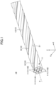
- FIG. 1 is a perspective view of the optical fiber-embedded PC steel strand of the present embodiment.
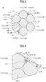
- FIG. 2 illustrates a configuration example of a cross section of an optical fiber-embedded PC steel strand 10 and the PC steel strand 11 as illustrated in FIG. 1 , the cross section being perpendicular to the longitudinal direction thereof.
- FIG. 3 is a partially enlarged view of FIG. 2 .
- FIG. 4 is an explanatory view of a cross section of an optical fiber-embedded PC steel strand including an anticorrosive coating, the cross section being perpendicular to the longitudinal direction thereof.
- the optical fiber-embedded PC steel strand of the present embodiment may include the PC steel strand in which the plurality of PC steel wires are twisted together, and the optical fiber.
- the optical fiber is fixed with the resin in the twist groove that is the groove between the two PC steel wires that are disposed at the outer surface of the PC steel strand and are next to each other.
- the PC in the PC steel strand or the PC steel wires means prestressed concrete.
- the optical fiber-embedded PC steel strand 10 as illustrated in FIG. 1 includes the PC steel strand 11 in which a plurality of PC steel wires 111, which are wires made of steel, are twisted together. Each of the PC steel wires 111 bears a tension after the tension has been introduced to the optical fiber-embedded PC steel strand 10.
- An X axis in FIG. 1 is an axis along the longitudinal direction of the optical fiber-embedded PC steel strand 10 and the PC steel strand 11. Also, a YZ plane formed by a Y axis and a Z axis that are orthogonal to the X axis is a cross section perpendicular to the longitudinal direction of the optical fiber-embedded PC steel strand 10 and the PC steel strand 11.
- the number of the PC steel wires 111 forming the PC steel strand 11 can be selected in accordance with, for example, performance required for the optical fiber-embedded PC steel strand and a manner in which the optical fiber-embedded PC steel strand is used.
- the number of the PC steel wires 111 is, for example, seven or nineteen.
- the PC steel strand 11 can form a mono-layered twisted structure in which six PC steel wires 111B to serve as outer peripheral wires are helically twisted around the outer periphery of one PC steel wire 111A to serve as the center wire, as illustrated in FIG.
- FIG. 1 and FIG. 2 illustrate an example in which PC steel wires having the same outer diameters are used as the PC steel wire 111A to serve as the center wire and the PC steel wires 111B to serve as the outer peripheral wires.
- the outer diameter of the PC steel wire 111A to serve as the center wire may be different from the outer diameter of the PC steel wires 111B to serve as the outer peripheral wires.
- the PC steel strand can form an unillustrated bi-layered twisted structure in which PC steel wires to serve as inner peripheral wires and PC steel wires to serve as outer peripheral wires are helically twisted in order around one PC steel wire to serve as the center wire.
- PC steel wires to serve as inner peripheral wires and PC steel wires to serve as outer peripheral wires are helically twisted in order around one PC steel wire to serve as the center wire.
- one of the types is a structure including one center wire, nine inner peripheral wires, and nine outer peripheral wires
- the other type is a structure including one center wire, six inner peripheral wires, and twelve outer peripheral wires.
- the center wire and the outer peripheral wires can be PC steel wires having approximately the same outer diameters
- the inner peripheral wires can be PC steel wires having smaller outer diameters than the outer diameter of the center wire.
- the center wire and the inner peripheral wires can be PC steel wires having approximately the same outer diameters.
- the outer peripheral wires can be an alternating arrangement of: PC steel wires having approximately the same outer diameters as the outer diameter of the center wire; and PC steel wires having outer diameters smaller than the PC steel wires having approximately the same outer diameters as the outer diameter of the center wire.
- the PC steel strand 11 has a recessed portion formed between two PC steel wires 111B that are disposed at an outer surface 11A of the PC steel strand 11 and are next to each other, i.e., a twist groove 21 that is a groove between the outer peripheral wires.
- the PC steel strand 11 has an inner gap 22 that is a space enclosed by three PC steel wires 111 that are next to each other.
- the twist groove 21 and the inner gap 22 have a helical shape about a center axis A serving as the center so as to extend along the longitudinal direction of the PC steel strand 11.
- the inner gap 22 is formed between the PC steel wire 111A to serve as the center wire and the PC steel wires 111B to serve as two outer peripheral wires.
- the inner gap is formed between the center wire and two inner peripheral wires, between one inner peripheral wire and two outer peripheral wires, and between two inner peripheral wires and one outer peripheral wire.
- the optical fiber-embedded PC steel strand can include the optical fiber as described above.
- the optical fiber that is suitably usable includes a core and a cladding.
- the materials of the core and the cladding include plastics and quartz glass.
- the optical fiber can utilize an optical fiber wire including a primary coating on the outer periphery of the cladding, an optical fiber core wire further including a secondary coating, or an optical fiber code further including a reinforcing material on the outer periphery of the secondary coating and a sheath covering the outer periphery of the reinforcing material.
- Examples of the material of the primary coating include UV-curable resins.
- the secondary coating include flame-retardant polyester elastomers.
- the material of the reinforcing material include glass fibers, carbon fibers, aramid fibers, and the like.
- Examples of the material of the sheath include flame-retardant polyolefins such as flame-retardant polyethylene, flame-retardant crosslinked polyolefins such as flame-retardant crosslinked polyethylene, heat-resistant vinyl, and the like.
- the optical fiber included in the optical fiber-embedded PC steel strand is preferably, for example, one or more optical fibers selected from single-mode optical fibers, multi-mode optical fibers, and polarization maintaining optical fibers.
- the strain and the temperature of the PC steel strand can be measured.
- the optical fiber-embedded PC steel strand of the present embodiment may include only one optical fiber, or two or more optical fibers.
- the strain and the temperature can be measured. Therefore, for example, the optical fiber-embedded PC steel strand of the present embodiment may include a strain measurement optical fiber and a temperature measurement optical fiber in accordance with measurement applications.
- the strain measurement optical fiber and the temperature measurement optical fiber it is possible to use an optical fiber of an appropriate type in accordance with, for example, measurement conditions such as scattering light used in the respective measurements and the like.
- the outer diameter of the optical fiber is disposed in the twist groove. Therefore, the outer diameter of the optical fiber is preferably selected so that the optical fiber can be housed in the twist groove.
- the outer diameter of the optical fiber is, for example, preferably 1.5 mm or less and more preferably 1.0 mm or less.
- the optical fiber can be readily housed in the twist groove of the PC steel strand.
- the outer dimeter of the optical fiber is preferably 0.235 mm or more and more preferably 0.8 mm or more.
- the optical fiber is also preferably excellent in durability because heat or an external force may be applied to the optical fiber during the production process of the optical fiber-embedded PC steel strand or upon setting the optical fiber-embedded PC steel strand in structures.
- the durability of the optical fiber can be increased when the outer dimeter of the optical fiber is 0.235 mm or more.
- the outer dimeter of the optical fiber means the outer dimeter of the entire optical fiber including coatings such as the primary coating and the secondary coating as described above.
- an elongation at break of the optical fiber is preferably 3.5% or more.
- the optical fiber can conform to deformation of the PC steel strand.
- the elongation at break of the PC steel strand is 3.5% or more. Therefore, the optical fiber having an elongation at break of 3.5% or more can deform in accordance with deformation of the PC steel strand even if a force for the PC steel strand or the optical fiber to break is applied to the optical fiber-embedded PC steel strand. Accordingly, when the elongation at break of the optical fiber is 3.5% or more, the optical fiber readily deforms in accordance with the PC steel strand of the optical fiber-embedded PC steel strand to which the tension has been introduced, and durability of the optical fiber-embedded PC steel strand can be improved.
- the elongation at break of the optical fiber and the resin can be measured in accordance with JIS G 3536 (2014), which stipulates the same conditions as the conditions for the PC steel strand applied to the optical fiber-embedded PC steel strand.
- a tensile test can be performed to evaluate the elongation at break.
- the tensile test is performed for the optical fiber-embedded PC steel strand and the elongation of the optical fiber-embedded PC steel strand is 3.5% or more, if the optical fiber and the resin do not break, these members can be evaluated to have an elongation at break of 3.5% or more.
- a tensile strength of the optical fiber is preferably 100 MPa or more and 1,500 MPa or less and more preferably 120 MPa or more and 1,300 MPa or less.
- the optical fiber-embedded PC steel strand is, in use, set in a concrete structure and the like. Then, the ends of the optical fiber-embedded PC steel strand are pulled, thereby introducing a tension thereto and applying a compressive force into the concrete structure. In this way, a tensile stress occurring when the concrete structure receives a load is controlled, thereby preventing formation of cracks and the like in the concrete structure.
- a force is also applied to the optical fiber.
- the tensile strength of the optical fiber is 100 MPa or more, it is possible to prevent breakage of the optical fiber if a usual amount of the tension is introduced to the optical fiber-embedded PC steel strand.
- the tensile strength of the optical fiber is preferably 1,500 MPa or less.
- the tensile strength of the optical fiber and the resin is calculated by dividing a tensile strength value by a cross-sectional area of a sample thereof subjected to evaluation.
- the tensile strength value is measured using a tensile tester at a tensile speed of 5 mm/min and a supporting distance of 150 mm.
- the optical fiber 12 is fixed with a resin 13 in the twist groove 21 of the PC steel strand 11.
- the inventors of the present invention measured an optical fiber for a strain distribution after introduction of a uniform tension to an optical fiber-embedded PC steel strand, and then studied a cause of occurrence of the difference in the measured value of strain in accordance with the positions along the longitudinal direction of the optical fiber-embedded PC steel strand. As a result, they have found that the cause of occurrence of the difference in the measured value is variation in position of the optical fiber disposed in a twist groove in a plurality of cross sections of the optical fiber-embedded PC steel strand that are perpendicular to the longitudinal direction of the optical fiber-embedded PC steel strand.
- an optical fiber-embedded PC steel strand has been produced in the following manner. Specifically, an optical fiber is disposed in a resin or the like to form an optical fiber member. The optical fiber member is disposed in the twist groove of a PC steel strand, followed by fixing with an adhesive or the like.
- the optical fiber member which includes the optical fiber, the resin, and the like, has higher rigidity than the rigidity of the optical fiber alone. Therefore, there is difficulty in disposing and fixing the optical fiber member in the twist groove of the PC steel strand. Due to the above-described difficulty in attaching the optical fiber member to the PC steel strand, the position in the twist groove of the optical fiber member or the optical fiber disposed in the optical fiber member may become unstable.
- the optical fiber is preferably fixed with the resin in the twist groove of the PC steel strand. That is, in the optical fiber-embedded PC steel strand of the present embodiment, the optical fiber is preferably directly disposed in the twist groove without being previously coated with the resin or the like, followed by fixing with the resin.
- the resin 13 is preferably a resin that is curable in a short time so as to prevent displacement of the position of the optical fiber 12 after disposition of the optical fiber 12 at a desired position in the twist groove 21 of the PC steel strand 11.
- the curing time of the resin 13 is preferably one minute or shorter and more preferably 50 seconds or shorter.
- the resin 13, of the resin having a curing time of one minute or shorter can shorten the time required until the fixing with the resin after the optical fiber 12 has been disposed at a desired position in the twist groove 21. Therefore, it is possible to prevent displacement of the position of the optical fiber 12 which would otherwise occur before the resin 13 is cured.
- the optical fiber 12 in the plurality of cross sections of the optical fiber-embedded PC steel strand that are perpendicular to the longitudinal direction of the optical fiber-embedded PC steel strand, it is possible to set the optical fiber 12 at a desired position in the twist groove 21 with high accuracy, e.g., it is possible to set the optical fiber 12 with high accuracy at a position in the twist groove 21 at which the optical fiber 12 is initially disposed.
- the curing time is preferably 0.1 seconds or longer and more preferably 0.3 seconds or longer.
- the curing time thereof is 0.1 seconds or longer, for example, it is possible to prevent clogging of a nozzle or the like that supplies the resin 13.
- the above-described curing time means a time from the start of a curing treatment under curing conditions predetermined in accordance with the type of the resin, until the resin is cured.
- the curing conditions predetermined in accordance with the type of the resin include heating conditions for thermosetting resins such as a heating temperature, and irradiating conditions of ultraviolet rays for UV-curable resins.
- the expression "the resin is cured” means that when the surface of a test sample of the resin is lightly touched with a fingertip, the resin does not become attached to the fingertip.
- thermosetting resin a thermosetting resin, a UV-curable resin, a two-liquid mixing-type resin, or the like can be used.
- the two-liquid mixing-type resin means a resin that starts curing upon mixing of two types of liquid.
- the UV-curable resin can be especially preferably used.
- a reason for this is as follows. Specifically, the UV-curable resin can be cured only by irradiation with ultraviolet rays, and compared to the case of performing heating or the like, it is possible to suppress impacts to members other than the resin 13, such as the optical fiber. Also, compared to the thermosetting resin, the two-liquid mixing-type resin, or the like, the UV-curable resin often has a short curing time. Thus, it is possible to especially prevent displacement of the position of the optical fiber 12 in the twist groove 21 which would otherwise occur before the resin 13 is cured.
- the elongation at break of the resin is preferably 3.5% or more.
- the resin can preferably conform to deformation of the PC steel strand.
- the elongation at break of the PC steel strand is 3.5% or more. Therefore, the resin having an elongation at break of 3.5% or more can deform in accordance with deformation of the PC steel strand even if a force for the PC steel strand or the resin to break is applied to the optical fiber-embedded PC steel strand. Accordingly, when the elongation at break of the resin is 3.5% or more, the resin readily deforms in accordance with the PC steel strand of the optical fiber-embedded PC steel strand to which the tension has been introduced, and durability of the optical fiber-embedded PC steel strand can be improved.
- a tensile strength of the resin is preferably 100 MPa or more and 300 MPa or less and more preferably 120 MPa or more and 250 MPa or less.
- the optical fiber-embedded PC steel strand is, in use, set in the concrete structure and the like. Then, the ends of the optical fiber-embedded PC steel strand are pulled, thereby introducing a tension thereto and applying a compressive force into the concrete structure. In this way, a tensile stress occurring when the concrete structure receives a load is controlled, thereby preventing formation of cracks and the like in the concrete structure.
- a force is also applied to the resin that fixes the optical fiber.
- the tensile strength of the resin is 100 MPa or more, it is possible to prevent breakage of the resin if a usual amount of the tension is introduced to the optical fiber-embedded PC steel strand.
- the tensile strength of the resin is preferably 300 MPa or less.
- the optical fiber 12 can be disposed in the twist groove 21 of the PC steel strand 11 and fixed with the resin 13 as described above.
- the optical fiber 12 By disposing the optical fiber 12 in the twist groove 21 of the PC steel strand 11, the optical fiber 12 readily follows stretching of the PC steel strand 11. Therefore, the strain occurring in the PC steel strand 11 is reflected to the optical fiber 12, and the strain or the like of the PC steel strand 11 can be measured using the optical fiber 12 with high accuracy.
- the outer surface of the optical fiber 12 is preferably covered with the resin 13.
- the optical fiber 12 By covering the outer surface of the optical fiber 12 with the resin 13, the optical fiber 12 can be firmly fixed to the PC steel strand 11, and can especially accurately conform to stretching of the PC steel strand 11. Therefore, the strain occurring in the PC steel strand 11 is especially accurately reflected to the optical fiber 12, and the strain of the PC steel strand 11 can be measured using the optical fiber 12 with especially high accuracy. Also, by covering the outer surface of the optical fiber 12 with the resin 13, it is possible to protect the optical fiber 12 and prevent damage to the optical fiber 12.
- the coefficient of variation in distance between the common tangent of the two PC steel wires that form the twist groove and are next to each other, and the center of the optical fiber is preferably 0.5 or less, as measured in 10 cross sections of the PC steel strand that are perpendicular to the longitudinal direction of the PC steel strand.
- the coefficient of variation is more preferably 0.4 or less.
- the inventors of the present invention measured a strain distribution along the longitudinal direction of an optical fiber-embedded PC steel strand to which a uniform tension has been introduced, and then studied a cause of occurrence of the difference in the measured value of strain in accordance with the positions along the longitudinal direction of the optical fiber-embedded PC steel strand.
- the cause of occurrence of the difference in the measured value i.e., the cause of occurrence of the range of variation, is variation in position of the optical fiber disposed in a twist groove in a plurality of cross sections of the optical fiber-embedded PC steel strand that are perpendicular to the longitudinal direction of the optical fiber-embedded PC steel strand.
- FIG. 3 is an enlarged view of the vicinity of the optical fiber 12 of FIG. 2 .
- FIG. 3 is a cross-sectional view of the optical fiber-embedded PC steel strand 10 and the PC steel strand 11 in a plain perpendicular to the longitudinal direction thereof.
- a distance L12 denotes a distance between a common tangent 311 of the two PC steel wires 111B that form the twist groove 21 of the PC steel strand 11 and are next to each other, and a center 121 of the optical fiber 12.
- the fact that the coefficient of variation in the distance L12 measured in the 10 cross sections of the PC steel strand 11 that are perpendicular to the longitudinal direction of the PC steel strand 11 is 0.5 or less means suppressed variation in the distance L12 in the 10 measured cross sections.
- the common tangent 311 is, in the above-described cross section, a common tangent that is drawn so as to contact the two PC steel wires 111B at two points and so that the two points are positioned on an external exposed surface of the PC steel strand 11.
- the coefficient of variation is a parameter indicating a degree of variation in measured values.
- the coefficient of variation is a value calculated by dividing a standard deviation of the measured values by an average value of the measured values, and is a dimensionless number.
- the coefficient of variation is preferably 0.05 or more and more preferably 0.1 or more.
- the coefficient of variation is 0.05 or more, it is possible to shorten the time required for positioning the optical fiber in the production of the optical fiber-embedded PC steel strand, and thus can increase productivity.
- the optical fiber-embedded PC steel strand of the present embodiment includes a plurality of optical fibers
- at least one of the optical fibers preferably satisfies the above-described coefficient of variation and more preferably all of the optical fibers satisfy the above-described coefficient of variation.
- the optical fiber By disposing the optical fiber so as to satisfy the above-described coefficient of variation, it is possible to suppress variation in position of the optical fiber along the longitudinal direction of the optical fiber-embedded PC steel strand. As a result, it is possible to measure the strain using the optical fiber-embedded PC steel strand with high accuracy.
- the entire optical fiber is preferably housed in the twist groove of the PC steel strand. More preferably, the optical fiber is disposed especially at a position close to the bottom of the twist groove of the PC steel strand.
- a straight line 312 is a straight line that is parallel to the common tangent 311 and 0.1 mm apart from the common tangent 311 inward of the PC steel strand 11.
- the straight line 312 is disposed at a position closer to a center A1 of the PC steel strand 11 than the common tangent 311 is.
- the center A1 is the center of a circumscribed circle C1 of the PC steel strand 11 in the cross section perpendicular to the longitudinal direction of the PC steel strand 11 (see FIG. 2 ).
- a distance L312 between the common tangent 311 and the straight line 312 in FIG. 3 is 0.1 mm.
- the optical fiber 12 is preferably positioned in a region 33 enclosed by the straight line 312 and surfaces 32 of the two PC steel wires 111B that form the twist groove 21 and are next to each other. Note that, the fact that the optical fiber 12 is positioned in the region 33 means that the entire optical fiber 12 is positioned in the region 33 in the cross section for evaluation.
- the evaluation of the position of the optical fiber 12 in the twist groove 21 is preferably performed in a plurality of cross sections.
- the evaluation thereof is performed in 10 cross sections.
- the 10 cross sections for use are preferably, for example, the same 10 cross sections as used for determining the coefficient of variation in the distance L12 between the common tangent 311 of the two PC steel wires 111B that form the twist groove 21 and are next to each other, and the center 121 of the optical fiber 12.
- the optical fiber 12 is positioned in the region 33. More preferably, in nine or more cross sections thereof, the optical fiber 12 is positioned in the region 33. Even more preferably, in all of the evaluated cross sections, the optical fiber 12 is positioned in the region 33.
- optical fiber 12 By disposing the optical fiber 12 in the region 33, it is possible to dispose the optical fiber 12 in proximity to the PC steel strand 11, and measure the strain of the PC steel strand with higher accuracy.
- the optical fiber-embedded PC steel strand of the present embodiment includes a plurality of optical fibers
- at least one of the optical fibers is preferably disposed in the region 33 and more preferably all of the optical fibers are disposed in the region 33.
- the optical fiber-embedded PC steel strand 10 of the present embodiment may include only one optical fiber, or two or more optical fibers. However, the optical fiber-embedded PC steel strand 10 of the present embodiment preferably includes two or more optical fibers.
- a reason for this is as follows. Specifically, when the optical fiber-embedded PC steel strand includes two or more optical fibers, even if one of the optical fibers is damaged, for example, during construction, due to aging, or the like, the strain measurement and the like can be performed using another optical fiber.
- the strain and the temperature of the PC steel strand can be measured based on the scattering light using the optical fiber
- the two or more optical fibers may be required, for example, when the strain and the temperature are measured at the same time, or in accordance with measurement systems of the strain and the temperature. Therefore, in order to adapt to various measurement systems, the optical fiber-embedded PC steel strand preferably includes two or more optical fibers.
- the optical fiber-embedded PC steel strand 10 preferably includes a pair of optical fibers 12A and 12B at point-symmetric positions with a point of symmetry being the center A1 of the circumscribed circle C1 of the PC steel strand 11 in the cross section perpendicular to the longitudinal direction of the PC steel strand 11. That is, for example, the optical fiber-embedded PC steel strand 10 preferably includes the pair of optical fibers 12A and 12B at both end portions of the diameter of the circumscribed circle C1 of the PC steel strand 11.
- the optical fibers 12A and 12B can be respectively disposed so as to be along a twist groove 21A and a twist groove 21B that are at the point-symmetric positions with the point of symmetry being the center A1 of the circumscribed circle C1 of the PC steel strand 11.
- the pair of optical fibers 12A and 12B at the point-symmetric positions with the point of symmetry being the center A1 of the circumscribed circle C1 of the PC steel strand 11, it is possible to dispose the optical fibers apart from each other in the optical fiber-embedded PC steel strand 10. Therefore, for example, even if the optical fiber 12A is damaged, it is possible to suppress damage to the optical fiber 12B disposed apart therefrom.
- the disposition of the optical fibers is not limited to the above disposition.
- a plurality of optical fibers may be disposed in the same twist groove.
- the optical fiber-embedded PC steel strand of the present embodiment may further include the anticorrosive coating that coats the outer surface of the PC steel strand.
- FIG. 4 is a cross-sectional view of the optical fiber-embedded PC steel strand 40 including the anticorrosive coating, the cross-sectional view being in a plane perpendicular to the longitudinal direction of the PC steel strand 11.
- the optical fiber-embedded PC steel strand 40 may be formed to have the same configuration as the configuration of the above-described optical fiber-embedded PC steel strand, except that an anticorrosive coating 41 and an outer coating 42 as described below are included.
- the optical fiber-embedded PC steel strand 40 including the anticorrosive coating may include the anticorrosive coating 41 that coats the outer surface 11A of the PC steel strand 11.
- the anticorrosive coating 41 can protect the PC steel strand 11 from an external environment and suppress corrosion of the PC steel strand 11.
- An outer surface 41A of the anticorrosive coating 41 may have, for example, a shape along the outer profile of the PC steel strand 11. However, this shape is by no means a limitation.
- the material (quality of material) of the anticorrosive coating 41 No particular limitation is imposed on the material (quality of material) of the anticorrosive coating 41.
- a resin excellent in corrosion resistance or grease can be used.
- the resin include epoxy resins and polyethylene resins.
- the polyethylene resin especially, it is preferable to use a high-density polyethylene resin.
- the high-density polyethylene resin means a material having a density of 0.942 g/cm 3 or higher. The density of the material is measured in accordance with JIS K 6922 (2016).
- the anticorrosive coating may be disposed in the inner gap 22.
- grease can be suitably used as the material of the anticorrosive coating.
- the grease may include, for example, petroleum-based hydrocarbon, thickeners, lubricating oil additives, and the like. As described above, the grease may be used as the anticorrosive coating 41 that coats the outer surface 11A of the PC steel strand 11.
- the optical fiber-embedded PC steel strand 40 may include the outer coating 42 that further coats the outer surface 41A of the anticorrosive coating 41.
- the anticorrosive coating 41 and the outer coating 42 may be formed of the same material, but are preferably formed of different materials. A reason for this is as follows. Specifically, the outer coating 42 can have the function of preventing degradation mainly due to ultraviolet rays. However, when the anticorrosive coating 41 is formed only of the material for the outer coating 42, there is a risk of raising in cost.
- the material (quality of material) of the outer coating 42 No particular limitation is imposed on the material (quality of material) of the outer coating 42.
- examples thereof include polyethylene resins.
- the polyethylene resin especially, it is preferable to use a high-density polyethylene resin.
- the strain measurement method of the present embodiment is a strain measurement method of measuring strain of the PC steel strand using the optical fiber-embedded PC steel strand according to the present disclosure, and may include the following step.
- the strain measurement method of the present embodiment may measure a temperature using the optical fiber and correct the strain measured in the strain measurement step.
- the strain measurement method of the present embodiment may further include the following steps.
- the scattering light used in the strain measurement step is not limited.
- one or more selected from Brillouin scattering light, Rayleigh scattering light, and Raman scattering light can be used.
- the number of the optical fibers included in the optical fiber-embedded PC steel strand used for the measurement may be selected in accordance with the measurement system and the like.
- the number of the optical fibers is preferably an even number of two or more, or when the measurement system is BOTDR, FBG, or BOCDR, the number of the optical fibers is preferably one or more.
- the measurement of a temperature can be performed using the optical fiber included in the optical fiber-embedded PC steel strand according to the present disclosure. Note that, in the temperature measurement step, it is possible to measure the temperature at a given position along the longitudinal direction of the optical fiber, and a temperature distribution along the longitudinal direction of the optical fiber. However, as described below, because the strain measured in the strain measurement step is corrected with the temperature measured in the temperature measurement step, it is preferable to measure the temperature and the temperature distribution at positions corresponding to the positions at which the strain and the strain distribution are measured in the strain measurement step.
- the scattering light used in the temperature measurement step is not limited.
- one or more selected from Brillouin scattering light, Rayleigh scattering light, and Raman scattering light can be used.
- the number of the optical fibers included in the optical fiber-embedded PC steel strand used for the measurement may be selected in accordance with the measurement system and the like.
- the number of the optical fibers is preferably an even number of two or more, or when the measurement system is BOTDR, FBG, BOCDR, or ROTDR, the number of the optical fibers is preferably one or more.
- the temperature measurement can be performed at a given timing.
- the scattering light may be influenced not only by the strain occurring in the optical fiber in response to the strain of the PC steel strand, but also by the ambient temperature of the optical fiber.
- the type of the scattering light used in the strain measurement step and the type of the scattering light used in the temperature measurement step are preferably different from each other.
- the measurement of the strain is performed using the optical fiber based on Brillouin scattering light or Rayleigh scattering light
- the measurement of the temperature is performed using the optical fiber based on Raman scattering light.
- the optical fiber-embedded PC steel strand When the strain measurement step and the temperature measurement step are performed, the optical fiber-embedded PC steel strand according to the present disclosure can be used.
- the optical fiber-embedded PC steel strand preferably includes a plurality of optical fibers.
- the optical fiber-embedded PC steel strand preferably includes, as the optical fibers, the strain measurement optical fiber and the temperature measurement optical fiber.
- the strain measurement optical fiber or the temperature measurement optical fiber is preferably one or more optical fibers selected from single-mode optical fibers, multi-mode optical fibers, and polarization maintaining optical fibers.
- optical fibers suitable for the scattering light used in the strain measurement step and the temperature measurement step are preferably selected as the strain measurement optical fiber and the temperature measurement optical fiber.
- the single-mode optical fiber when Brillouin scattering light or Rayleigh scattering light is used, it is preferable to use the single-mode optical fiber, or when Raman scattering light is used, it is preferable to use the multi-mode optical fiber.
- a reason for this is as follows. Specifically, when the measurement is performed based on Brillouin scattering light or Rayleigh scattering light, an especially sharp peak can be obtained by the use of the single-mode optical fiber. Also, when the measurement is performed based on Raman scattering light, an especially high peak intensity can be obtained by the use of the multi-mode optical fiber.
- the strain measurement optical fiber is preferably the single-mode optical fiber.
- the temperature measurement optical fiber is preferably the multi-mode optical fiber.
- the optical fiber of a type suitable for the scattering light used it is possible to especially increase the measurement accuracy.
- the strain measured in the strain measurement step can be corrected using the temperature measured in the temperature measurement step.
- the strain after correction can be calculated by the following formula (1).
- (Strain (%) after correction) (strain (%) measured in the strain measurement step) - (temperature (°C) measured in the temperature measurement step) ⁇ (temperature coefficient (%/°C)) ... (1)
- the temperature coefficient can be previously calculated using, for example, the same optical fiber-embedded PC steel strand as used in the measurement based on a relationship between known temperatures and known quantities of strain.
- the strain measurement method of the present embodiment which uses the optical fiber-embedded PC steel strand according to the present disclosure, it is possible to suppress an error and measure strain and the like with high accuracy.
- the measurements of the strain and the temperature can be performed using the optical fiber-embedded PC steel strand. Therefore, the strain and the temperature can be readily measured even if the measurements thereof are hard to perform from the exterior, e.g., when the optical fiber-embedded PC steel strand is, for example, embedded. Also, for example, compared to the case of measuring the temperature using a thermometer other than the optical fiber-embedded PC steel strand, it is possible to correct the strain with the temperature with high accuracy and measure the strain with high accuracy because a measurement point of the strain and a measurement point of the temperature are in proximity to each other.
- the strain and the temperature are measured using the scattering light.
- the degree of burden in performing an on-site measurement is small, and it is possible to readily perform the measurement.
- the strain measurement device of the present embodiment may include the optical fiber-embedded PC steel strand according to the present disclosure and the scattering light measurement device connected to the optical fiber-embedded PC steel strand.
- FIG. 5 and FIG. 6 illustrate strain measurement devices 500 and 600 including the optical fiber-embedded PC steel strand.
- a scattering light measurement device 50 as illustrated in FIG. 5 is a type of a scattering light measurement device configured to input and output laser beams to and from both ends of the optical fiber. This can be used for performing the measurement through, for example, BOCDA or BOTDA.
- a scattering light measurement device 60 as illustrated in FIG. 6 is a type of a measurement device configured to input and output laser beams to and from one end of the optical fiber. This can be used for performing the measurement through, for example, BOTDR, FBG, BOCDR, or ROTDR.
- the scattering light measurement device 50 or 60 includes an optical signal transmission part 501 configured to transmit an optical signal, and an optical signal reception part 502 configured to receive the optical signal from the optical fiber. Also, the scattering light measurement device 50 or 60 includes an analysis part 503 configured to analyze the optical signal received by the optical signal reception part 502 and obtain one or more types of information selected from the strain and the temperature of the optical fiber. If necessary, the scattering light measurement device 50 or 60 may include a display part 504 configured to display the information obtained by the analysis part 503.
- the optical signal transmission part 501 and the optical signal reception part 502 may be configured as, for example, an integrated measurement device.
- the analysis part 503 is, for example, a calculation device such as a computer
- the display part 504 is, for example, a display monitor configured to display, on a screen, the calculation result obtained by the calculation device.
- a personal computer or the like that integrally includes the analysis part 503 and the display part 504 may be used.
- first ends 511A and 512A of the optical fibers are routed out of a first end 51A of the optical fiber-embedded PC steel strand.
- the first ends 511A and 512A are connected to each other.
- second ends 511B and 512B of the optical fibers are pulled out of a second end 51B of the optical fiber-embedded PC steel strand 51 and connected to the scattering light measurement device 50.
- a first end 521A of the single optical fiber 521 is disposed at a first end 52A of the optical fiber-embedded PC steel strand 52.
- a second end 521B of the optical fiber 521 included in the optical fiber-embedded PC steel strand 52 is pulled out of a second end 52B of the optical fiber-embedded PC steel strand 52 and connected to the scattering light measurement device 60.
- the optical signal transmission part 501, the optical signal reception part 502, and the optical fibers 511, 512, and 521 are appropriately connected to each other via a light splitter 506, a coupler 507, or the like.
- the strain measurement device of the present embodiment may include the scattering light measurement device adapted for the measurement system used for measuring the strain and the temperature using the scattering light, and may include both of the scattering light measurement device 50 and the scattering light measurement device 60.
- the optical fiber-embedded PC steel strand used for the above-described strain measurement method may include the strain measurement optical fiber and the temperature measurement optical fiber. Therefore, for example, the strain measurement device of the present embodiment may include the scattering light measurement device connected to the strain measurement optical fiber and the scattering light measurement device connected to the temperature measurement optical fiber. Also, for example, the strain measurement device of the present embodiment may include a single scattering light measurement device that may be configured to change the connection of the optical fiber and the like to the interior of the scattering light measurement device or the scattering light measurement device between the measurement of the strain and the measurement of the temperature.
- the scattering light measurement device 50 or 60 may include a calculation part 505 configured to perform calculation for the correction.
- the strain measurement device of the present embodiment includes a plurality of scattering light measurement devices
- the plurality of scattering light measurement devices may share the single calculation part 505.
- the scattering light measurement device 50 or 60 may be provided with a plurality of calculation parts 505 and may be configured to share information necessary for correction between the plurality of calculation parts 505.
- the calculation part 505 may be provided separately from the scattering light measurement device.
- the scattering light measurement device 50 or 60 may include an interface 508 configured to output measurement data such as data of the measured strain and temperature, the corrected strain, and the like, to the exterior.
- the interface 508 includes interfaces for LAN (Local Area Network) and various interfaces for connecting to recording media and the like.
- the scattering light measurement device including the interface can output data of the measured strain and temperature, data of the corrected strain, and the like, to the exterior.
- the scattering light measurement device may be configured to output data of the above strain and the like to an external information terminal from the interface via a network or the like. With this configuration, it is possible to readily obtain data such as strain of a concrete structure in a remote place.
- strain measurement device of the present embodiment which uses the optical fiber-embedded PC steel strand according to the present disclosure, it is possible to suppress a range of variation in measurement value of strain in accordance with positions along the longitudinal direction of the optical fiber-embedded PC steel strand, and to measure strain and the like with high accuracy.
- the measurements of the strain and the temperature can be performed using the optical fiber-embedded PC steel strand. Therefore, the strain and the temperature can be readily measured even if the measurements thereof are hard to perform from the exterior, e.g., when the optical fiber-embedded PC steel strand is, for example, embedded. Also, for example, compared to the case of measuring the temperature using a thermometer other than the optical fiber-embedded PC steel strand, it is possible to correct the strain with the temperature with high accuracy because a measurement point of the strain and a measurement point of the temperature are in proximity to each other.
- the strain and the temperature are measured using the scattering light.
- the degree of burden in performing an on-site measurement is small, and it is possible to readily perform the measurement.
- the production method for the optical fiber-embedded PC steel strand of the present embodiment may include the disposing step and the fixing step as described below.
- the disposing step can dispose an optical fiber in a twist groove that is a groove between two PC steel wires of a plurality of PC steel wires twisted together to form a PC steel strand, the two PC steel wires being disposed at an outer surface of the PC steel strand and being next to each other.
- the fixing step can fix the optical fiber in the twist groove with a resin.
- a tension of more than 0 N and 20 N or less can be applied to the optical fiber.
- FIG. 7 schematically illustrates a production apparatus 70 for the optical fiber-embedded PC steel strand that performs the production method for the optical fiber-embedded PC steel strand of the present embodiment.
- the PC steel strand 11 is transferred from left to right along an arrow B1.
- the method for transferring the PC steel strand 11. may be transferred in a roll-to-roll system, or may be transferred by pulling the PC steel strand 11 with a winch or the like.
- the optical fiber 12 can be disposed in the twist groove 21 of the PC steel strand 11.
- the optical fiber member is formed by coating the outer surface of the optical fiber with the resin or the like, and then is disposed in the twist groove 21 of the PC steel strand 11. Meanwhile, in the production method for the optical fiber-embedded PC steel strand of the present embodiment, the optical fiber 12 is directly disposed in the twist groove 21.
- the optical fiber has excellent handleability because the optical fiber has rigidity lower than the optical fiber member. Therefore, compared to the optical fiber member, use of the optical fiber alone can increase workability in the disposing step.
- a tension is applied to the optical fiber, e.g., a tension of more than 0 N and 20 N or less is preferably applied to the optical fiber, and more preferably a tension of 7 N or more and 15 N or less is applied to the optical fiber.
- the optical fiber 12 By applying the tension of more than 0 N to the optical fiber, positioning of the optical fiber 12 to be fed can be readily performed, and the optical fiber 12 can be set at a desired position in the twist groove 21 of the PC steel strand 11. Therefore, in the plurality of cross sections of the optical fiber-embedded PC steel strand that are perpendicular to the longitudinal direction of the optical fiber-embedded PC steel strand, it is possible to suppress variation in position of the optical fiber disposed in the twist groove. Accordingly, when the strain distribution of the obtained optical fiber-embedded PC steel strand is measured along the longitudinal direction thereof after the tension has been uniformly introduced thereto, it is possible to suppress the range of variation in the measured value of strain in accordance with the positions along the longitudinal direction thereof. That is, use of the thus-produced optical fiber-embedded PC steel strand enables accurate measurement of strain.
- No particular limitation is imposed on the method of applying the tension to the optical fiber 12.
- Examples thereof include a method of pulling a reel 71 configured to feed the optical fiber 12 along an arrow B2 in FIG. 7 , i.e., in a direction opposite to the arrow B1 in which the PC steel strand 11 is transferred. By adjusting a force to pull the reel 71, it is possible to adjust the magnitude of the tension to be applied to the optical fiber 12.
- an end of the optical fiber 12 is fixed in the twist groove 21 of the PC steel strand 11 before the start of the disposing step, and during the disposing step, the optical fiber 12 can be pulled together with the PC steel strand 11 along the arrow B1 in FIG. 7 from left to right in the drawing. Therefore, further examples of the method of applying the tension to the optical fiber 12 include a method of adjusting a force to pull the PC steel strand 11 and the optical fiber 12.
- the tension of more than 0 N and 20 N or less is preferably applied to the optical fiber 12.
- twist groove 21 it is preferable to adjust the twist groove 21 to be always positioned at a place where the optical fiber 12 is fed from the reel 71, by rotating the PC steel strand 11 about the center axis A while pulling the PC steel strand 11 along the arrow B1.
- the optical fiber-embedded PC steel strand includes two or more optical fibers, preferably, a plurality of reels 71 are provided in the same number as the number of the optical fibers, and a plurality of optical fibers are supplied at the same time.
- the above-described tension is preferably applied to each of the optical fibers. Then, it is possible to dispose each optical fiber in a predetermined twist groove.
- a guiding path which is configured to guide the optical fiber 12, between the PC steel strand 11 and the reel 71 above a transfer path of the optical fiber 12 so that the optical fiber 12 fed from the reel 71 can be especially accurately disposed at a desired position in the twist groove 21.
- the guiding path may be configured of, for example, a guiding roller, or a guide provided with a groove that passes the optical fiber 12 therethrough.
- the optical fiber 12 may be pressed and inserted into a desired position in the twist groove 21 by an insertion roller or the like.
- a resin-supplying step as described below may also be performed.
- a portion of the insertion roller to contact the optical fiber 12 preferably has a shape that is curved correspondingly to the outer shape of the optical fiber 12.
- a portion of the insertion roller to contact the twist groove 21 preferably has a shape that corresponds to the twist groove 21.
- the optical fiber can be fixed in the twist groove with a resin. Specifically, for example, by curing the resin, the optical fiber can be fixed in the twist groove.
- the method of curing the resin which may be selected in accordance with the type of the resin.
- the resin is a thermosetting resin
- the resin is a UV-curable resin
- the production apparatus 70 for the optical fiber-embedded PC steel strand may include a resin-curing device 73.
- the resin-curing device 73 may be a heating device including a heater or the like.
- the resin-curing device 73 may be an ultraviolet ray irradiating device including a UV lamp configured to irradiate the resin or the like with ultraviolet rays.
- the resin-supplying step the resin is supplied to the twist groove.
- the timing at which the resin-supplying step is performed is imposed on the timing at which the resin-supplying step is performed.
- the optical fiber may be disposed in the twist groove. That is, the resin-supplying step, the disposing step, and the fixing step may be performed in order.
- the resin may be supplied to the twist groove. That is, the resin-supplying step may be performed after the disposing step and before performing the fixing step, and the disposing step, the resin-supplying step, and the fixing step may be performed in order.
- the resin-supplying step which supplies the resin to the twist groove
- the disposing step and before performing the fixing step it is possible to supply the resin over a wide range of the outer surface of the optical fiber. Therefore, the optical fiber can be firmly fixed to the PC steel strand and can especially accurately conform to stretching of the PC steel strand. As a result, the strain occurring in the PC steel strand is especially accurately reflected to the optical fiber, and the strain of the PC steel strand can be measured using the optical fiber with especially high accuracy.
- the production apparatus 70 for the optical fiber-embedded PC steel strand may include a resin-supplying device 72.
- a resin-supplying device 72 No particular limitation is imposed on the configuration of the resin-supplying device 72.
- the amount of the resin supplied is preferably 15 g/m or less and more preferably 10 g/m or less per unit length of the twist groove. This is because when the amount of the resin supplied is 15 g/m or less, running and the like of the resin can be prevented.
- the amount of the resin supplied is preferably more than 1 g/m and more preferably 2 g/m or more per unit length of the twist groove.
- the optical fiber can be fixed in the twist groove with sufficient strength.
- the resin can be supplied to at least the twist groove 21 in which the optical fiber 12 is disposed.
- the resin may also be supplied to the twist groove 21 in which the optical fiber is not disposed.
- the resin may be supplied to not only the twist groove 21 but also the entire surface of the PC steel strand 11.
- the resin-supplying device 72 can be configured so that the PC steel strand passes through a resin tank in which the resin is reserved.
- the resin-supplying device 72 may also include a resin-removing device so as to be able to remove the excessively supplied resin, for example, when the resin is excessively supplied.
- the resin-removing device can be a device with a spatula, a die, or the like so as to be able to remove the excessive resin attached to the surface of the PC steel strand 11.
- the resin for use is preferably a resin that is curable in a short time so as to prevent displacement of the position of the optical fiber 12 after disposition of the optical fiber 12 at a desired position in the twist groove 21 of the PC steel strand 11.
- the curing time of the resin 13 supplied in the resin-supplying step is preferably one minute or shorter and more preferably 50 seconds or shorter.
- the resin 13, of the resin having a curing time of one minute or shorter can shorten the time required until the fixing with the resin after the optical fiber 12 has been disposed at a desired position in the twist groove 21. Therefore, it is possible to prevent displacement of the position of the optical fiber 12 which would otherwise occur before the resin 13 is cured.
- the optical fiber 12 in the plurality of cross sections of the optical fiber-embedded PC steel strand that are perpendicular to the longitudinal direction of the optical fiber-embedded PC steel strand, it is possible to set the optical fiber 12 at a desired position in the twist groove 21 with high accuracy, e.g., it is possible to set the optical fiber 12 with high accuracy at a position in the twist groove at which the optical fiber 12 is initially disposed.
- the curing time is preferably 0.1 seconds or longer and more preferably 0.3 seconds or longer.
- the curing time thereof is 0.1 seconds or longer, for example, it is possible to prevent clogging of a nozzle or the like that supplies the resin 13.
- thermosetting resin a thermosetting resin, a UV-curable resin, a two-liquid mixing-type resin, or the like can be used.
- the UV-curable resin can be especially preferably used.
- a reason for this is as follows. Specifically, the UV-curable resin can be cured only by irradiation with ultraviolet rays, and compared to the case of performing heating or the like, it is possible to suppress impacts to members other than the resin 13, such as the optical fiber. Also, compared to the thermosetting resin, the two-liquid mixing-type resin, or the like, the UV-curable resin often has a short curing time. Thus, it is possible to especially prevent displacement of the position of the optical fiber 12 in the twist groove 21 which would otherwise occur before the resin 13 is cured.
- the resin is a UV-curable resin
- the resin can be irradiated with ultraviolet rays in the fixing step as described above.
- the optical fiber-embedded PC steel strand of the present embodiment may include the anticorrosive coating. Therefore, the production method for the optical fiber-embedded PC steel strand of the present embodiment may include, if necessary, an anticorrosive coating-forming step and an outer coating-forming step as described below.
- the anticorrosive coating-forming step for example, it is possible to supply and coat a constituting resin and the like of the anticorrosive coating to the outer surface of the optical fiber-embedded PC steel strand in which the optical fiber is fixed with the resin to the surface of the PC steel strand.
- the anticorrosive coating-forming step if necessary, it is possible to further perform heating and the like, and form the anticorrosive coating on the outer surface of the optical fiber-embedded PC steel strand.
- the outer coating-disposing step for example, it is possible to form the outer coating 42 by molding, through extrusion molding or the like, a constituting resin of the outer coating 42 to the outer periphery of the anticorrosive coating 41.
- optical fiber-embedded PC steel strands produced in the following Experimental Examples were each measured for the distance between the common tangent 311 of the two PC steel wires 111 that formed the twist groove 21 and were next to each other, and the center 121 of the optical fiber 12 in 10 measurement cross sections perpendicular to the longitudinal direction thereof (hereinafter also referred to as "measurement cross sections for measurement of the coefficient of variation").
- the common tangent 311 was, in each of the above measurement cross sections, drawn so as to contact the two PC steel wires 111B at two points and so that the two points were positioned on an external exposed surface of the PC steel strand 11.
- optical fiber-embedded PC steel strands produced in each of the Experimental Examples some of the produced optical fiber-embedded PC steel strands were subjected to the present test and the others were subjected to the following measurement of a strain distribution.
- the coefficient of variation was calculated from the values measured in the 10 cross sections.
- the optical fiber-embedded PC steel strands each including two optical fibers were produced. Therefore, for each of the optical fibers, the coefficient of variation in distance between the above-described common tangent and the center of the optical fiber was determined.
- the optical fiber-embedded PC steel strand produced in each of the following Experimental Examples was pulled.
- the optical fiber-embedded PC steel strand to which a tension had been introduced was measured for a strain distribution.
- a tension 0.7 times the lower limit of the maximum testing force described in JIS G 3536 (2014) was introduced to the optical fiber-embedded PC steel strand.
- the measurement of the strain was performed according to the following procedure.
- the scattering light measurement device 60 was connected to the optical fiber included in the optical fiber-embedded PC steel strand produced in the following Experimental Examples, and the strain distribution was measured through BOTDR using Brillouin scattering light (strain measurement step).
- a variation range percentage i.e., a percentage of a range of variation that is the difference between the maximum value and the minimum value, relative to the maximum value, was calculated by the following formula (2).
- (Variation range percentage (%)) [(Range of variation) ⁇ (Maximum value)] ⁇ 100
- the variation range percentage that was 30 or less was evaluated as A
- the variation range percentage that was more than 3% and 60 or less was evaluated as B
- the variation range percentage that was more than 6% was evaluated as C.
- the evaluation result that was A or B means suppression of the range of variation in the measured values of the strain in accordance with the positions along the longitudinal direction of the optical fiber-embedded PC steel strand.
- the evaluation result that was C means a wide range of variation in the measured values of the strain in accordance with the positions along the longitudinal direction of the optical fiber-embedded PC steel strand.
- the evaluation results are presented in the row "Variation range percentage of strain" in Table 1.
- the variation range percentage of strain was calculated using the result of the strain distribution measured using the optical fiber whose coefficient of variation was presented in Table 1.
- Experimental Example 1 to Experimental Example 3 are Working Examples
- Experimental Example 4 is a Comparative Example.
- optical fiber-embedded PC steel strand production apparatus Using the same apparatus as the optical fiber-embedded PC steel strand production apparatus as illustrated in FIG. 7 except that two reels feeding the optical fibers were used and two optical fibers were fed from the reels, optical fiber-embedded PC steel strands were produced.
- a cross section of the produced optical fiber-embedded PC steel strands perpendicular to the longitudinal direction of the optical fiber-embedded PC steel strands has a structure as illustrated in FIG. 2 .
- the optical fiber-embedded PC steel strands include the PC steel strand 11 in which seven PC steel wires 111 were twisted together. Note that, the outer dimeter of the PC steel strand 11 was 15.2 mm. Then, the optical fibers 12A and 12B were respectively disposed in the twist grooves 21A and 21B each formed between the PC steel wires 111 that were the outer wires of the PC steel strand 11 next to each other. Note that, as the optical fibers 12A and 12B, a single-mode optical fiber having an outer dimeter of 0.9 mm and an elongation at break of 3.50 or more was used.
- the optical fibers 12A and 12B are each disposed in the region 33 enclosed by the straight line 312 and the surfaces 32 of the two PC steel wires 111 that form the twist groove and are next to each other.
- the straight line 312 is a straight line that is parallel to the common tangent 311 of the two PC steel wires 111 next to each other and in which the distance L312 between the common tangent 311 and the straight line 312 is 0.1 mm.
- the obtained optical fiber-embedded PC steel strand was observed for the positions of the optical fibers 12A and 12B in 10 measurement cross sections for measurement of the coefficient of variation.
- the optical fibers 12A and 12B were disposed in the respective regions 33 in all of the measurement cross sections for measurement of the coefficient of variation.
- the optical fibers 12A and 12B were disposed in the respective regions 33 in all of the measurement cross sections for measurement of the coefficient of variation.
- optical fiber-embedded PC steel strand was produced according to the following procedure.
- the optical fiber 12 to be fed from the reel 71 was previously fixed to the twist groove 21 at the right-hand end in FIG. 7 of the PC steel strand 11, and was pulled and transferred together with the PC steel strand along the arrow B1.
- the tension to be applied to each of the optical fibers 12 was adjusted to 3 N. The above tension is applied to each optical fiber 12 until the optical fiber 12 is fixed with the resin in the fixing step after the feeding from the reel in the disposing step.
- the optical fiber 12 was disposed in the twist groove of the PC steel strand.
- the resin As the resin, a UV-curable resin having a tensile strength of 200 MPa and an elongation at break of 3.50 or more was used. Note that, the UV-curable resin used was cured for 0.5 seconds by irradiation with ultraviolet rays using a UV lamp. That is, the resin used had a curing time of 0.5 seconds.
- the resin was supplied using the pneumatic resin-supplying device 72.
- the resin was supplied so that the coating amount would be 5 g/m per unit length of the twist groove.
- the resin supplied in the resin-supplying step was irradiated with ultraviolet rays by the resin-curing device 73 including a UV lamp, followed by solidifying, thereby fixing the optical fiber in the twist groove of the PC steel strand.
- optical fiber-embedded PC steel strand The evaluation results of the obtained optical fiber-embedded PC steel strand are presented in Table 1. Note that, the optical fiber-embedded PC steel strand obtained in Experimental Example 1, a standard deviation determined for calculating the coefficient of variation presented in Table 1 was 0.095 cm.
- Optical fiber-embedded PC steel strands were produced and evaluated under the same conditions as in Experimental Example 1 except that in the disposing step, the tension to be applied to each optical fiber was changed to 10 N (Experimental Example 2) or 20 N (Experimental Example 3).
- the obtained optical fiber-embedded PC steel strand was observed for the positions of the optical fibers 12A and 12B in 10 measurement cross sections for measurement of the coefficient of variation.
- the optical fibers 12A and 12B were disposed outward of the respective regions 33 in six of the measurement cross sections for measurement of the coefficient of variation.
- Experimental Example 1 Experimental Example 2
- Experimental Example 3 Experimental Example 4
- Variation range percentage of strain B A A C
- Table 1 From the results presented in Table 1, it could be confirmed that the optical fibe-embedded PC steel strands of Exmperimental Example 1 to Experimental Example 3, which were produced by applying the tension of more than 0 N and 20 N or less in the disposing step, were able to be suppressed in the coefficient of variation compared to the optical fiber-embedded PC steel strand of Experimental Example 4.
Landscapes
- Physics & Mathematics (AREA)
- Engineering & Computer Science (AREA)
- Architecture (AREA)
- General Physics & Mathematics (AREA)
- Civil Engineering (AREA)
- Structural Engineering (AREA)
- Mechanical Engineering (AREA)
- Optics & Photonics (AREA)
- Length Measuring Devices By Optical Means (AREA)
- Reinforcement Elements For Buildings (AREA)
Abstract
Description
- The present disclosure relates to optical fiber-embedded PC steel strands, strain measurement devices, and production methods for optical fiber-embedded PC steel strands.
- The present application claims priority to
Japanese Patent Application No. 2021-134853, filed on August 20, 2021 - Patent Literature 1 discloses a PC steel strand including: a PC steel wire group including a plurality of PC steel wires that are twisted together; and an optical fiber member, the optical fiber member including: an optical fiber including an optical fiber core and a coating on the optical fiber core; and a resin filler enclosing the optical fiber, in which the optical fiber member is disposed so as to extend between and along the PC steel wires next to each other, and in a cross section orthogonal to a longitudinal direction of the PC steel wire group, the optical fiber member is housed in a region enclosed by the respective surfaces of the PC steel wires next to each other and a common tangent of the PC steel wires next to each other.
- Patent Literature 1:
Japanese Laid-Open Patent Publication No. 2016-57231 - An optical fiber-embedded PC steel strand of the present disclosure includes: a PC steel strand in which a plurality of PC steel wires are twisted together; and an optical fiber. The optical fiber is fixed with a resin in a twist groove that is a groove between two PC steel wires of the PC steel wires, the two PC steel wires being disposed at an outer surface of the PC steel strand and being next to each other. A coefficient of variation in distance between: a common tangent of the two PC steel wires that form the twist groove and are next to each other; and a center of the optical fiber is 0.5 or less, as measured in 10 cross sections of the PC steel strand that are perpendicular to a longitudinal direction of the PC steel strand.
-
- [
FIG. 1] FIG. 1 is a perspective view of an optical fiber-embedded PC steel strand according to one embodiment of the present disclosure. - [
FIG. 2] FIG. 2 is a cross-sectional view of the optical fiber-embedded PC steel strand ofFIG. 1 in a plane perpendicular to a longitudinal direction thereof. - [
FIG. 3] FIG. 3 is an enlarged view of a vicinity of the optical fiber ofFIG. 2 . - [
FIG. 4] FIG. 4 is a cross-sectional view of an optical fiber-embedded PC steel strand including an anticorrosive coating, the cross-sectional view being in a plane perpendicular to a longitudinal direction thereof. - [
FIG. 5] FIG. 5 is an explanatory view of a scattering light measurement device according to one embodiment of the present disclosure. - [
FIG. 6] FIG. 6 is an explanatory view of a scattering light measurement device according to one embodiment of the present disclosure. - [
FIG. 7] FIG. 7 is an explanatory view of a production apparatus for the optical fiber-embedded PC steel strand. - Concrete structures have such a property that is prone to a tensile force. In view thereof, in order to previously apply a compressive force to such concrete structures, control a tensile stress occurring when the concrete structures receive a load, and prevent formation of cracks and the like, a tendon such as a PC steel strand or the like is used.
- Also, using, as the tendon, the optical fiber-including PC steel strand disclosed in Patent Literature 1 or the like, measurement of a strain distribution of the PC steel strand along the longitudinal direction of the PC steel strand, evaluation of a tension introduced to the PC steel strand, and the like are performed by the optical fiber and based on the scattering light.
- When a strain distribution is measured using an optical fiber after introduction of a uniform tension by pulling the ends of an existing optical fiber-embedded PC steel strand, the measured value may be found to be different in accordance with positions along the longitudinal direction of the optical fiber-embedded PC steel strand.
- The optical fiber-embedded PC steel strand may be required to further improve in measurement accuracy of strain depending on, for example, a place where it is installed. Therefore, there has been a need for an optical fiber-embedded PC strand that has suppressed occurrence of the difference in the measured value in accordance with positions along the longitudinal direction of the optical fiber-embedded PC steel strand, and enables accurate measurement of strain.
- It is an object of the present disclosure to provide an optical fiber-embedded PC steel strand that enables accurate measurement of strain.
- According to the present disclosure, it is possible to provide an optical fiber-embedded PC steel strand that enables accurate measurement of strain.
- First, embodiments of the present disclosure will be listed and described. In the following description, the same or corresponding elements are provided with the same symbols, and the same description thereof is not repeated.
- (1) An optical fiber-embedded PC steel strand according to one aspect of the present disclosure includes:
- a PC steel strand in which a plurality of PC steel wires are twisted together; and
- an optical fiber, in which
- the optical fiber is fixed with a resin in a twist groove that is a groove between two PC steel wires of the PC steel wires, the two PC steel wires being disposed at an outer surface of the PC steel strand and being next to each other, and
- a coefficient of variation in distance between: a common tangent of the two PC steel wires that form the twist groove and are next to each other; and a center of the optical fiber is 0.5 or less, as measured in 10 cross sections of the PC steel strand that are perpendicular to a longitudinal direction of the PC steel strand.
- The fact that the above-described coefficient of variation of the optical fiber-embedded PC steel strand according to one aspect of the present disclosure is 0.5 or less means suppressed variation in distance between the common tangent of the two PC steel wires, which form the twist groove and are next to each other, and the center of the optical fiber in the 10 measured cross sections. That is, this means suppressed variation in position of the optical fiber in the cross sections of the PC steel strand perpendicular to the longitudinal direction of the PC steel strand. Therefore, when a tension is uniformly introduced to the optical fiber-embedded PC steel strand and the resulting optical fiber-embedded PC steel strand is measured for a strain distribution along the longitudinal direction thereof, it is possible to suppress occurrence of the difference in the measured value of strain in accordance with the positions along the longitudinal direction thereof, i.e., a range of variation. Therefore, use of the optical fiber-embedded PC steel strand enables accurate measurement of strain.
- Note that, the coefficient of variation is a parameter indicating a degree of variation in measured values. The coefficient of variation is a value calculated by dividing a standard deviation of the measured values by an average value of the measured values, and is a dimensionless number.
- (2) In the cross section of the PC steel strand perpendicular to the longitudinal direction of the PC steel strand, the optical fiber may be positioned in a region enclosed by: a straight line that is parallel to the common tangent and 0.1 mm apart from the common tangent inward of the PC steel strand; and surfaces of the two PC steel wires that form the twist groove and are next to each other.
- By disposing the optical fiber in the above-described region, the optical fiber can be disposed in proximity to the PC steel strand and the strain of the PC steel strand can be measured with higher accuracy.
- (3) In the cross section of the PC steel strand perpendicular to the longitudinal direction of the PC steel strand, an outer surface of the optical fiber may be coated with the resin.
- By coating the outer surface of the optical fiber with the resin, the optical fiber can be firmly fixed to the PC steel strand and can especially accurately conform to stretching of the PC steel strand. Therefore, the strain occurring in the PC steel strand is especially accurately reflected to the optical fiber, and the strain of the PC steel strand can be measured using the optical fiber with especially high accuracy. Also, coating the outer surface of the optical fiber with the resin can protect the optical fiber and prevent damage to the optical fiber.
- (4) The optical fiber may be two or more.
- When the optical fiber-embedded PC steel strand includes two or more optical fibers, even if one of the optical fibers is damaged, for example, during construction, due to aging, or the like, the strain measurement and the like can be performed using another optical fiber.
- Although the strain and the temperature of the PC steel strand can be measured based on the scattering light using the optical fiber, the two or more optical fibers may be required, for example, when the strain and the temperature are measured at the same time, or in accordance with measurement systems of the strain and the temperature. Therefore, in order to adapt to various measurement systems, the optical fiber-embedded PC steel strand preferably includes two or more optical fibers.
- (5) An elongation at break of the resin may be 3.5% or more.
- According to JIS G 3536 (2014), an elongation at break of the PC steel strand is 3.5% or more. Therefore, the resin having an elongation at break of 3.5% or more can deform in accordance with deformation of the PC steel strand even if a force for the PC steel strand or the resin to break is applied to the optical fiber-embedded PC steel strand. Accordingly, when the elongation at break of the resin is 3.5% or more, the resin readily deforms in accordance with the PC steel strand of the optical fiber-embedded PC steel strand to which the tension has been introduced, and durability of the optical fiber-embedded PC steel strand can be improved.
- (6) An anticorrosive coating that coats the outer surface of the PC steel strand may be included.
- When the optical fiber-embedded PC steel strand includes the anticorrosive coating, it is possible to protect the PC steel strand from an external environment and to suppress corrosion of the PC steel strand.
- (7) A strain measurement device according to one aspect of the present disclosure includes:
- the optical fiber-embedded PC steel strand according to any one of (1) to (6); and
- a scattering light measurement device connected to the optical fiber-embedded PC steel strand.
- According to the strain measurement device according to one aspect of the present disclosure, which uses the optical fiber-embedded PC steel strand according to one aspect of the present disclosure, it is possible to suppress the range of variation in the measured value of strain in accordance with positions along the longitudinal direction of the optical fiber-embedded PC steel strand, and to measure the strain and the like with high accuracy.
- According to the strain measurement device according to one aspect of the present disclosure, the measurements of the strain and the temperature can be performed using the optical fiber-embedded PC steel strand. Therefore, the strain and the temperature can be readily measured even if the measurements thereof are hard to perform from the exterior, e.g., when the optical fiber-embedded PC steel strand is, for example, embedded. Also, for example, compared to the case of measuring the temperature using a thermometer other than the optical fiber-embedded PC steel strand, it is possible to correct the strain with the temperature with high accuracy because a measurement point of the strain and a measurement point of the temperature are in proximity to each other.
- Moreover, according to the strain measurement device according to one aspect of the present disclosure, the strain and the temperature are measured using the scattering light. Thus, the degree of burden in performing an on-site measurement is small, and it is possible to readily perform the measurement.
- (8) The scattering light measurement device may include an interface configured to output measurement data.
- The scattering light measurement device including the interface can output, to the exterior, data of the measured strain and temperature and data of the corrected strain. For example, the scattering light measurement device may be configured to output the data, such as the strain, to an external information terminal from the interface via a network or the like. With this configuration, it is possible to readily obtain data such as the strain of a concrete structure in a remote place.
- (9) A production method for the optical fiber-embedded PC steel strand according to one aspect of the present disclosure includes:
- a disposing step of disposing an optical fiber in a twist groove that is a groove between two PC steel wires of a plurality of PC steel wires twisted together to form a PC steel strand, the two PC steel wires being disposed at an outer surface of the PC steel strand and being next to each other; and
- a fixing step of fixing the optical fiber in the twist groove with a resin, in which
- in the disposing step, a tension of more than 0 N and 20 N or less is applied to the optical fiber.
- By applying the tension of more than 0 N to the optical fiber, positioning of the optical fiber to be fed can be readily performed, and the optical fiber can be set at a desired position in the twist groove of a
PC steel strand 11. Therefore, in a plurality of cross sections of the optical fiber-embedded PC steel strand that are perpendicular to the longitudinal direction of the optical fiber-embedded PC steel strand, it is possible to suppress variation in position of the optical fiber disposed in the twist groove. Accordingly, when a strain distribution of the obtained optical fiber-embedded PC steel strand is measured along the longitudinal direction thereof after a tension has been uniformly introduced thereto, it is possible to suppress the range of variation in the measured value of strain in accordance with positions along the longitudinal direction thereof. That is, use of the thus-produced optical fiber-embedded PC steel strand enables accurate measurement of strain. - When the tension to be applied to the optical fiber is 20 N or less, it is possible to prevent damage to the optical fiber.
- (10) After the disposing step and before performing the fixing step, a resin-supplying step of supplying the resin to the twist groove may be included.
- By supplying the resin to the twist groove after the disposing step and before performing the fixing step, it is possible to supply the resin over a wide range of the outer surface of the optical fiber. Therefore, the optical fiber can be firmly fixed to the PC steel strand and can especially accurately conform to stretching of the PC steel strand. As a result, the strain occurring in the PC steel strand is especially accurately reflected to the optical fiber, and the strain of the PC steel strand can be measured using the optical fiber with especially high accuracy.
- (11) A curing time of the resin may be one minute or shorter.
- Use of the resin having a curing time of one minute or shorter can shorten the time required until the fixing with the resin after the optical fiber has been disposed at a desired position in the twist groove. Therefore, it is possible to prevent displacement of the position of the optical fiber which would otherwise occur before the resin is cured. As a result, in the plurality of cross sections of the optical fiber-embedded PC steel strand that are perpendicular to the longitudinal direction of the optical fiber-embedded PC steel strand, it is possible to set the optical fiber at a desired position in the twist groove with high accuracy, e.g., it is possible to set the optical fiber with high accuracy at a position in the twist groove at which the optical fiber is initially disposed. Accordingly, when a strain distribution of the obtained optical fiber-embedded PC steel strand is measured along the longitudinal direction thereof after a tension has been uniformly introduced thereto, it is possible to especially suppress the range of variation in the measured value of strain in accordance with positions along the longitudinal direction thereof. That is, it is possible to measure the strain with especially high accuracy.
- (12) The resin is a UV-curable resin, and in the fixing step, the resin may be irradiated with ultraviolet rays.
- The UV-curable resin is a resin that is curable only by irradiation with ultraviolet rays. Thus, compared to the case of performing heating or the like, it is possible to suppress impacts to members other than the resin, such as the optical fiber. Also, compared to a thermosetting resin, a two-liquid mixing-type resin, or the like, the UV-curable resin often has a short curing time. Thus, it is possible to especially prevent displacement of the position of the optical fiber in the twist groove which would otherwise occur before the resin is cured.
- Specific examples of the optical fiber-embedded PC steel strand, the strain measurement device, or the production method for the optical fiber-embedded PC steel strand according to one embodiment of the present disclosure (hereinafter referred to as "the present embodiment") will be described below with reference to the drawings. Note that, the present invention is not limited to these examples, but is intended to encompass all changes within the meaning and scope that are recited in the claims and are equivalent to the claims.
- A configuration example of the optical fiber-embedded PC steel strand of the present embodiment will be described with reference to
FIG. 1 to FIG. 4 . -
FIG. 1 is a perspective view of the optical fiber-embedded PC steel strand of the present embodiment.FIG. 2 illustrates a configuration example of a cross section of an optical fiber-embeddedPC steel strand 10 and thePC steel strand 11 as illustrated inFIG. 1 , the cross section being perpendicular to the longitudinal direction thereof.FIG. 3 is a partially enlarged view ofFIG. 2 .FIG. 4 is an explanatory view of a cross section of an optical fiber-embedded PC steel strand including an anticorrosive coating, the cross section being perpendicular to the longitudinal direction thereof. - The optical fiber-embedded PC steel strand of the present embodiment may include the PC steel strand in which the plurality of PC steel wires are twisted together, and the optical fiber. The optical fiber is fixed with the resin in the twist groove that is the groove between the two PC steel wires that are disposed at the outer surface of the PC steel strand and are next to each other.
- Note that, the PC in the PC steel strand or the PC steel wires means prestressed concrete.
- First, the PC steel strand, the optical fiber, and the resin, which are members included in the optical fiber-embedded PC steel strand of the present embodiment, will be described.
- The optical fiber-embedded
PC steel strand 10 as illustrated inFIG. 1 includes thePC steel strand 11 in which a plurality ofPC steel wires 111, which are wires made of steel, are twisted together. Each of thePC steel wires 111 bears a tension after the tension has been introduced to the optical fiber-embeddedPC steel strand 10. - An X axis in
FIG. 1 is an axis along the longitudinal direction of the optical fiber-embeddedPC steel strand 10 and thePC steel strand 11. Also, a YZ plane formed by a Y axis and a Z axis that are orthogonal to the X axis is a cross section perpendicular to the longitudinal direction of the optical fiber-embeddedPC steel strand 10 and thePC steel strand 11. - No particular limitation is imposed on the number of the
PC steel wires 111 forming thePC steel strand 11. The number of thePC steel wires 111 forming thePC steel strand 11 can be selected in accordance with, for example, performance required for the optical fiber-embedded PC steel strand and a manner in which the optical fiber-embedded PC steel strand is used. The number of thePC steel wires 111 is, for example, seven or nineteen. When the number of thePC steel wires 111 is seven, thePC steel strand 11 can form a mono-layered twisted structure in which sixPC steel wires 111B to serve as outer peripheral wires are helically twisted around the outer periphery of onePC steel wire 111A to serve as the center wire, as illustrated inFIG. 1 andFIG. 2 . In this case, thePC steel wires 111B to serve as the outer peripheral wires are positioned at the outermost periphery of thePC steel strand 11.FIG. 1 andFIG. 2 illustrate an example in which PC steel wires having the same outer diameters are used as thePC steel wire 111A to serve as the center wire and thePC steel wires 111B to serve as the outer peripheral wires. However, such an embodiment is by no means a limitation. For example, the outer diameter of thePC steel wire 111A to serve as the center wire may be different from the outer diameter of thePC steel wires 111B to serve as the outer peripheral wires. - Meanwhile, when the number of PC steel wires is nineteen, the PC steel strand can form an unillustrated bi-layered twisted structure in which PC steel wires to serve as inner peripheral wires and PC steel wires to serve as outer peripheral wires are helically twisted in order around one PC steel wire to serve as the center wire. Typically, there are two types having different combinations of the number of inner peripheral wires and the number of outer peripheral wires.
- Specifically, one of the types is a structure including one center wire, nine inner peripheral wires, and nine outer peripheral wires, and the other type is a structure including one center wire, six inner peripheral wires, and twelve outer peripheral wires. In the former type, the center wire and the outer peripheral wires can be PC steel wires having approximately the same outer diameters, and the inner peripheral wires can be PC steel wires having smaller outer diameters than the outer diameter of the center wire.
- In the latter type, the center wire and the inner peripheral wires can be PC steel wires having approximately the same outer diameters. The outer peripheral wires can be an alternating arrangement of: PC steel wires having approximately the same outer diameters as the outer diameter of the center wire; and PC steel wires having outer diameters smaller than the PC steel wires having approximately the same outer diameters as the outer diameter of the center wire.
- As illustrated in
FIG. 2 , thePC steel strand 11 has a recessed portion formed between twoPC steel wires 111B that are disposed at anouter surface 11A of thePC steel strand 11 and are next to each other, i.e., atwist groove 21 that is a groove between the outer peripheral wires. Also, thePC steel strand 11 has aninner gap 22 that is a space enclosed by threePC steel wires 111 that are next to each other. Thetwist groove 21 and theinner gap 22 have a helical shape about a center axis A serving as the center so as to extend along the longitudinal direction of thePC steel strand 11. - When the
PC steel strand 11 is the mono-layered twisted structure as illustrated inFIG. 1 andFIG. 2 , i.e., the number of the PC steel wires included in thePC steel strand 11 is seven, theinner gap 22 is formed between thePC steel wire 111A to serve as the center wire and thePC steel wires 111B to serve as two outer peripheral wires. - When the PC steel strand is the bi-layered twisted structure, i.e., the number of the PC steel wires included in the PC steel strand is nineteen or the like, the inner gap is formed between the center wire and two inner peripheral wires, between one inner peripheral wire and two outer peripheral wires, and between two inner peripheral wires and one outer peripheral wire.
- The optical fiber-embedded PC steel strand can include the optical fiber as described above.
- The optical fiber that is suitably usable includes a core and a cladding. Examples of the materials of the core and the cladding include plastics and quartz glass. The optical fiber can utilize an optical fiber wire including a primary coating on the outer periphery of the cladding, an optical fiber core wire further including a secondary coating, or an optical fiber code further including a reinforcing material on the outer periphery of the secondary coating and a sheath covering the outer periphery of the reinforcing material. Examples of the material of the primary coating include UV-curable resins. Examples of the secondary coating include flame-retardant polyester elastomers. Examples of the material of the reinforcing material include glass fibers, carbon fibers, aramid fibers, and the like. Examples of the material of the sheath include flame-retardant polyolefins such as flame-retardant polyethylene, flame-retardant crosslinked polyolefins such as flame-retardant crosslinked polyethylene, heat-resistant vinyl, and the like.
- No particular limitation is imposed on the type of the optical fiber included in the optical fiber-embedded PC steel strand. The optical fiber included in the optical fiber-embedded PC steel strand is preferably, for example, one or more optical fibers selected from single-mode optical fibers, multi-mode optical fibers, and polarization maintaining optical fibers.
- By using the optical fiber included in the optical fiber-embedded PC steel strand and utilizing scattering light, the strain and the temperature of the PC steel strand can be measured. When the strain and the temperature are measured, it is preferable to use Brillouin scattering light, Rayleigh scattering light, Raman scattering light, or the like as the scattering light. Therefore, it is possible to select a suitable optical fiber in accordance with scattering light to be used, measurement accuracy to be required, and the like.
- The optical fiber-embedded PC steel strand of the present embodiment may include only one optical fiber, or two or more optical fibers. For example, by using the optical fiber of the optical fiber-embedded PC steel strand of the present embodiment, the strain and the temperature can be measured. Therefore, for example, the optical fiber-embedded PC steel strand of the present embodiment may include a strain measurement optical fiber and a temperature measurement optical fiber in accordance with measurement applications. As the strain measurement optical fiber and the temperature measurement optical fiber, it is possible to use an optical fiber of an appropriate type in accordance with, for example, measurement conditions such as scattering light used in the respective measurements and the like.
- No particular limitation is imposed on the outer diameter of the optical fiber. In the optical fiber-embedded PC steel strand of the present embodiment, the optical fiber is disposed in the twist groove. Therefore, the outer diameter of the optical fiber is preferably selected so that the optical fiber can be housed in the twist groove. The outer diameter of the optical fiber is, for example, preferably 1.5 mm or less and more preferably 1.0 mm or less.
- When the outer dimeter of the optical fiber is 1.5 mm or less, the optical fiber can be readily housed in the twist groove of the PC steel strand.
- No particular limitation is imposed on the lower limit of the outer dimeter of the optical fiber. However, the outer dimeter of the optical fiber is preferably 0.235 mm or more and more preferably 0.8 mm or more. The optical fiber is also preferably excellent in durability because heat or an external force may be applied to the optical fiber during the production process of the optical fiber-embedded PC steel strand or upon setting the optical fiber-embedded PC steel strand in structures. The durability of the optical fiber can be increased when the outer dimeter of the optical fiber is 0.235 mm or more.
- Note that, the outer dimeter of the optical fiber means the outer dimeter of the entire optical fiber including coatings such as the primary coating and the secondary coating as described above.
- Also, an elongation at break of the optical fiber is preferably 3.5% or more.
- Preferably, the optical fiber can conform to deformation of the PC steel strand. According to JIS G 3536 (2014), the elongation at break of the PC steel strand is 3.5% or more. Therefore, the optical fiber having an elongation at break of 3.5% or more can deform in accordance with deformation of the PC steel strand even if a force for the PC steel strand or the optical fiber to break is applied to the optical fiber-embedded PC steel strand. Accordingly, when the elongation at break of the optical fiber is 3.5% or more, the optical fiber readily deforms in accordance with the PC steel strand of the optical fiber-embedded PC steel strand to which the tension has been introduced, and durability of the optical fiber-embedded PC steel strand can be improved. Note that, in the present specification, the elongation at break of the optical fiber and the resin can be measured in accordance with JIS G 3536 (2014), which stipulates the same conditions as the conditions for the PC steel strand applied to the optical fiber-embedded PC steel strand.
- Specifically, for example, after the production of the optical fiber-embedded PC steel strand, a tensile test can be performed to evaluate the elongation at break. When the tensile test is performed for the optical fiber-embedded PC steel strand and the elongation of the optical fiber-embedded PC steel strand is 3.5% or more, if the optical fiber and the resin do not break, these members can be evaluated to have an elongation at break of 3.5% or more.
- A tensile strength of the optical fiber is preferably 100 MPa or more and 1,500 MPa or less and more preferably 120 MPa or more and 1,300 MPa or less.
- The optical fiber-embedded PC steel strand is, in use, set in a concrete structure and the like. Then, the ends of the optical fiber-embedded PC steel strand are pulled, thereby introducing a tension thereto and applying a compressive force into the concrete structure. In this way, a tensile stress occurring when the concrete structure receives a load is controlled, thereby preventing formation of cracks and the like in the concrete structure. When the optical fiber-embedded PC steel strand is pulled for introduction of the tension, a force is also applied to the optical fiber. When the tensile strength of the optical fiber is 100 MPa or more, it is possible to prevent breakage of the optical fiber if a usual amount of the tension is introduced to the optical fiber-embedded PC steel strand. However, because there is no need to excessively increase the tensile strength of the optical fiber, the tensile strength of the optical fiber is preferably 1,500 MPa or less.
- Note that, in the present specification, the tensile strength of the optical fiber and the resin is calculated by dividing a tensile strength value by a cross-sectional area of a sample thereof subjected to evaluation. The tensile strength value is measured using a tensile tester at a tensile speed of 5 mm/min and a supporting distance of 150 mm.
- In the optical fiber-embedded
PC steel strand 10 of the present embodiment, theoptical fiber 12 is fixed with aresin 13 in thetwist groove 21 of thePC steel strand 11. - The inventors of the present invention measured an optical fiber for a strain distribution after introduction of a uniform tension to an optical fiber-embedded PC steel strand, and then studied a cause of occurrence of the difference in the measured value of strain in accordance with the positions along the longitudinal direction of the optical fiber-embedded PC steel strand. As a result, they have found that the cause of occurrence of the difference in the measured value is variation in position of the optical fiber disposed in a twist groove in a plurality of cross sections of the optical fiber-embedded PC steel strand that are perpendicular to the longitudinal direction of the optical fiber-embedded PC steel strand.
- Hitherto, for example, an optical fiber-embedded PC steel strand has been produced in the following manner. Specifically, an optical fiber is disposed in a resin or the like to form an optical fiber member. The optical fiber member is disposed in the twist groove of a PC steel strand, followed by fixing with an adhesive or the like.
- However, there is difficulty in completely matching the outer shape of the optical fiber member with the shape of the twist groove and maintaining the shape thereof until the optical fiber member is fixed in the twist groove. Therefore, due to, for example, occurrence of a gap between the optical fiber member and the twist groove, the position in the twist groove of the optical fiber member or the optical fiber disposed in the optical fiber member may become unstable.
- Also, the optical fiber member, which includes the optical fiber, the resin, and the like, has higher rigidity than the rigidity of the optical fiber alone. Therefore, there is difficulty in disposing and fixing the optical fiber member in the twist groove of the PC steel strand. Due to the above-described difficulty in attaching the optical fiber member to the PC steel strand, the position in the twist groove of the optical fiber member or the optical fiber disposed in the optical fiber member may become unstable.
- In view thereof, in the optical fiber-embedded PC steel strand of the present embodiment, the optical fiber is preferably fixed with the resin in the twist groove of the PC steel strand. That is, in the optical fiber-embedded PC steel strand of the present embodiment, the optical fiber is preferably directly disposed in the twist groove without being previously coated with the resin or the like, followed by fixing with the resin.
- No particular limitation is imposed on the
resin 13. However, theresin 13 is preferably a resin that is curable in a short time so as to prevent displacement of the position of theoptical fiber 12 after disposition of theoptical fiber 12 at a desired position in thetwist groove 21 of thePC steel strand 11. - Specifically, for example, the curing time of the
resin 13 is preferably one minute or shorter and more preferably 50 seconds or shorter. - Use, as the
resin 13, of the resin having a curing time of one minute or shorter can shorten the time required until the fixing with the resin after theoptical fiber 12 has been disposed at a desired position in thetwist groove 21. Therefore, it is possible to prevent displacement of the position of theoptical fiber 12 which would otherwise occur before theresin 13 is cured. As a result, in the plurality of cross sections of the optical fiber-embedded PC steel strand that are perpendicular to the longitudinal direction of the optical fiber-embedded PC steel strand, it is possible to set theoptical fiber 12 at a desired position in thetwist groove 21 with high accuracy, e.g., it is possible to set theoptical fiber 12 with high accuracy at a position in thetwist groove 21 at which theoptical fiber 12 is initially disposed. - No particular limitation is imposed on the lower limit of the curing time of the
resin 13. However, the curing time is preferably 0.1 seconds or longer and more preferably 0.3 seconds or longer. When the curing time thereof is 0.1 seconds or longer, for example, it is possible to prevent clogging of a nozzle or the like that supplies theresin 13. - The above-described curing time means a time from the start of a curing treatment under curing conditions predetermined in accordance with the type of the resin, until the resin is cured. Examples of the curing conditions predetermined in accordance with the type of the resin include heating conditions for thermosetting resins such as a heating temperature, and irradiating conditions of ultraviolet rays for UV-curable resins. Also, the expression "the resin is cured" means that when the surface of a test sample of the resin is lightly touched with a fingertip, the resin does not become attached to the fingertip.
- No particular limitation is imposed on the
resin 13. However, a thermosetting resin, a UV-curable resin, a two-liquid mixing-type resin, or the like can be used. The two-liquid mixing-type resin means a resin that starts curing upon mixing of two types of liquid. - As the
resin 13, the UV-curable resin can be especially preferably used. A reason for this is as follows. Specifically, the UV-curable resin can be cured only by irradiation with ultraviolet rays, and compared to the case of performing heating or the like, it is possible to suppress impacts to members other than theresin 13, such as the optical fiber. Also, compared to the thermosetting resin, the two-liquid mixing-type resin, or the like, the UV-curable resin often has a short curing time. Thus, it is possible to especially prevent displacement of the position of theoptical fiber 12 in thetwist groove 21 which would otherwise occur before theresin 13 is cured. - Also, the elongation at break of the resin is preferably 3.5% or more.
- The resin can preferably conform to deformation of the PC steel strand. According to JIS G 3536 (2014), the elongation at break of the PC steel strand is 3.5% or more. Therefore, the resin having an elongation at break of 3.5% or more can deform in accordance with deformation of the PC steel strand even if a force for the PC steel strand or the resin to break is applied to the optical fiber-embedded PC steel strand. Accordingly, when the elongation at break of the resin is 3.5% or more, the resin readily deforms in accordance with the PC steel strand of the optical fiber-embedded PC steel strand to which the tension has been introduced, and durability of the optical fiber-embedded PC steel strand can be improved.
- A tensile strength of the resin is preferably 100 MPa or more and 300 MPa or less and more preferably 120 MPa or more and 250 MPa or less.
- The optical fiber-embedded PC steel strand is, in use, set in the concrete structure and the like. Then, the ends of the optical fiber-embedded PC steel strand are pulled, thereby introducing a tension thereto and applying a compressive force into the concrete structure. In this way, a tensile stress occurring when the concrete structure receives a load is controlled, thereby preventing formation of cracks and the like in the concrete structure. When the optical fiber-embedded PC steel strand is pulled for introducing the tension, a force is also applied to the resin that fixes the optical fiber. When the tensile strength of the resin is 100 MPa or more, it is possible to prevent breakage of the resin if a usual amount of the tension is introduced to the optical fiber-embedded PC steel strand. However, because there is no need to excessively increase the tensile strength of the resin, the tensile strength of the resin is preferably 300 MPa or less.
- Next, a configuration example of a suitable structure of the optical fiber-embedded PC steel strand will be described.
- As illustrated in
FIG. 2 , in the cross section of the optical fiber-embeddedPC steel strand 10 perpendicular to the longitudinal direction of thePC steel strand 11, i.e., in the cross section thereof perpendicular to a center axis A, theoptical fiber 12 can be disposed in thetwist groove 21 of thePC steel strand 11 and fixed with theresin 13 as described above. - By disposing the
optical fiber 12 in thetwist groove 21 of thePC steel strand 11, theoptical fiber 12 readily follows stretching of thePC steel strand 11. Therefore, the strain occurring in thePC steel strand 11 is reflected to theoptical fiber 12, and the strain or the like of thePC steel strand 11 can be measured using theoptical fiber 12 with high accuracy. - No particular limitation is imposed on the amount of the
resin 13 used when theoptical fiber 12 is fixed with theresin 13. For example, it is enough to dispose theresin 13 such that theoptical fiber 12 can be fixed to thePC steel strand 11. However, as illustrated inFIG. 2 , in the cross section perpendicular to the longitudinal direction of thePC steel strand 11, the outer surface of theoptical fiber 12 is preferably covered with theresin 13. - By covering the outer surface of the
optical fiber 12 with theresin 13, theoptical fiber 12 can be firmly fixed to thePC steel strand 11, and can especially accurately conform to stretching of thePC steel strand 11. Therefore, the strain occurring in thePC steel strand 11 is especially accurately reflected to theoptical fiber 12, and the strain of thePC steel strand 11 can be measured using theoptical fiber 12 with especially high accuracy. Also, by covering the outer surface of theoptical fiber 12 with theresin 13, it is possible to protect theoptical fiber 12 and prevent damage to theoptical fiber 12. - In the optical fiber-embedded PC steel strand of the present embodiment, the coefficient of variation in distance between the common tangent of the two PC steel wires that form the twist groove and are next to each other, and the center of the optical fiber is preferably 0.5 or less, as measured in 10 cross sections of the PC steel strand that are perpendicular to the longitudinal direction of the PC steel strand. The coefficient of variation is more preferably 0.4 or less.
- As described above, the inventors of the present invention measured a strain distribution along the longitudinal direction of an optical fiber-embedded PC steel strand to which a uniform tension has been introduced, and then studied a cause of occurrence of the difference in the measured value of strain in accordance with the positions along the longitudinal direction of the optical fiber-embedded PC steel strand. As a result, they have found that the cause of occurrence of the difference in the measured value, i.e., the cause of occurrence of the range of variation, is variation in position of the optical fiber disposed in a twist groove in a plurality of cross sections of the optical fiber-embedded PC steel strand that are perpendicular to the longitudinal direction of the optical fiber-embedded PC steel strand.
- Here, reference will be made to
FIG. 3 that is an enlarged view of the vicinity of theoptical fiber 12 ofFIG. 2 . Like inFIG. 2, FIG. 3 is a cross-sectional view of the optical fiber-embeddedPC steel strand 10 and thePC steel strand 11 in a plain perpendicular to the longitudinal direction thereof. - As illustrated in
FIG. 3 , in the optical fiber-embeddedPC steel strand 10 of the present embodiment, a distance L12 denotes a distance between acommon tangent 311 of the twoPC steel wires 111B that form thetwist groove 21 of thePC steel strand 11 and are next to each other, and acenter 121 of theoptical fiber 12. The fact that the coefficient of variation in the distance L12 measured in the 10 cross sections of thePC steel strand 11 that are perpendicular to the longitudinal direction of thePC steel strand 11 is 0.5 or less means suppressed variation in the distance L12 in the 10 measured cross sections. That is, this means suppressed variation in position of theoptical fiber 12 in the cross section of the PC steel strand perpendicular to the longitudinal direction of the PC steel strand. Therefore, when a tension is uniformly introduced to the optical fiber-embedded PC steel strand and the resulting optical fiber-embedded PC steel strand is measured for a strain distribution along the longitudinal direction thereof, it is possible to suppress occurrence of the difference in the measured value of strain in accordance with the positions along the longitudinal direction, i.e., a range of variation. Therefore, use of the optical fiber-embedded PC steel strand enables accurate measurement of strain. - As illustrated in
FIG. 3 , thecommon tangent 311 is, in the above-described cross section, a common tangent that is drawn so as to contact the twoPC steel wires 111B at two points and so that the two points are positioned on an external exposed surface of thePC steel strand 11. - Note that, the coefficient of variation is a parameter indicating a degree of variation in measured values. The coefficient of variation is a value calculated by dividing a standard deviation of the measured values by an average value of the measured values, and is a dimensionless number.
- No particular limitation is imposed on how to select the 10 cross sections used for measuring the distance L12. However, it is preferable to select the cross sections so that the distances between the cross sections for evaluation are equal to each other. Although in accordance with the length of a test piece, for example, it is preferable to select the cross sections for evaluation so that the distance between the cross sections next to each other is 50 cm.
- No particular limitation is imposed on the lower limit of the above-described coefficient of variation. However, for example, the coefficient of variation is preferably 0.05 or more and more preferably 0.1 or more. When the coefficient of variation is 0.05 or more, it is possible to shorten the time required for positioning the optical fiber in the production of the optical fiber-embedded PC steel strand, and thus can increase productivity.
- When the optical fiber-embedded PC steel strand of the present embodiment includes a plurality of optical fibers, at least one of the optical fibers preferably satisfies the above-described coefficient of variation and more preferably all of the optical fibers satisfy the above-described coefficient of variation.
- By disposing the optical fiber so as to satisfy the above-described coefficient of variation, it is possible to suppress variation in position of the optical fiber along the longitudinal direction of the optical fiber-embedded PC steel strand. As a result, it is possible to measure the strain using the optical fiber-embedded PC steel strand with high accuracy.
- However, in view that the optical fiber better follows stretching of the PC steel strand and accurately reflects the strain occurring in the PC steel strand to the optical fiber, the entire optical fiber is preferably housed in the twist groove of the PC steel strand. More preferably, the optical fiber is disposed especially at a position close to the bottom of the twist groove of the PC steel strand.
- For example, as illustrated in
FIG. 3 , in a cross section of the optical fiber-embeddedPC steel strand 10 perpendicular to the longitudinal direction of thePC steel strand 11, astraight line 312 is a straight line that is parallel to thecommon tangent 311 and 0.1 mm apart from thecommon tangent 311 inward of thePC steel strand 11. As illustrated inFIG. 3 , thestraight line 312 is disposed at a position closer to a center A1 of thePC steel strand 11 than thecommon tangent 311 is. The center A1 is the center of a circumscribed circle C1 of thePC steel strand 11 in the cross section perpendicular to the longitudinal direction of the PC steel strand 11 (seeFIG. 2 ). Also, a distance L312 between thecommon tangent 311 and thestraight line 312 inFIG. 3 is 0.1 mm. - In this case, the
optical fiber 12 is preferably positioned in aregion 33 enclosed by thestraight line 312 and surfaces 32 of the twoPC steel wires 111B that form thetwist groove 21 and are next to each other. Note that, the fact that theoptical fiber 12 is positioned in theregion 33 means that the entireoptical fiber 12 is positioned in theregion 33 in the cross section for evaluation. - The evaluation of the position of the
optical fiber 12 in thetwist groove 21 is preferably performed in a plurality of cross sections. For example, the evaluation thereof is performed in 10 cross sections. The 10 cross sections for use are preferably, for example, the same 10 cross sections as used for determining the coefficient of variation in the distance L12 between thecommon tangent 311 of the twoPC steel wires 111B that form thetwist groove 21 and are next to each other, and thecenter 121 of theoptical fiber 12. - Preferably, in eight or more cross sections of the 10 evaluated cross sections, the
optical fiber 12 is positioned in theregion 33. More preferably, in nine or more cross sections thereof, theoptical fiber 12 is positioned in theregion 33. Even more preferably, in all of the evaluated cross sections, theoptical fiber 12 is positioned in theregion 33. - By disposing the
optical fiber 12 in theregion 33, it is possible to dispose theoptical fiber 12 in proximity to thePC steel strand 11, and measure the strain of the PC steel strand with higher accuracy. - When the optical fiber-embedded PC steel strand of the present embodiment includes a plurality of optical fibers, at least one of the optical fibers is preferably disposed in the
region 33 and more preferably all of the optical fibers are disposed in theregion 33. - No particular limitation is imposed on the number of the optical fibers included in the optical fiber-embedded
PC steel strand 10 of the present embodiment. The optical fiber-embeddedPC steel strand 10 of the present embodiment may include only one optical fiber, or two or more optical fibers. However, the optical fiber-embeddedPC steel strand 10 of the present embodiment preferably includes two or more optical fibers. - A reason for this is as follows. Specifically, when the optical fiber-embedded PC steel strand includes two or more optical fibers, even if one of the optical fibers is damaged, for example, during construction, due to aging, or the like, the strain measurement and the like can be performed using another optical fiber.
- Although the strain and the temperature of the PC steel strand can be measured based on the scattering light using the optical fiber, the two or more optical fibers may be required, for example, when the strain and the temperature are measured at the same time, or in accordance with measurement systems of the strain and the temperature. Therefore, in order to adapt to various measurement systems, the optical fiber-embedded PC steel strand preferably includes two or more optical fibers.
- A configuration example of the optical fiber-embedded PC steel strand including two or more optical fibers will be described with reference to
FIG. 2 . For example, the optical fiber-embeddedPC steel strand 10 preferably includes a pair ofoptical fibers PC steel strand 11 in the cross section perpendicular to the longitudinal direction of thePC steel strand 11. That is, for example, the optical fiber-embeddedPC steel strand 10 preferably includes the pair ofoptical fibers PC steel strand 11. Specifically, theoptical fibers twist groove 21A and atwist groove 21B that are at the point-symmetric positions with the point of symmetry being the center A1 of the circumscribed circle C1 of thePC steel strand 11. - As described above, by disposing the pair of
optical fibers PC steel strand 11, it is possible to dispose the optical fibers apart from each other in the optical fiber-embeddedPC steel strand 10. Therefore, for example, even if theoptical fiber 12A is damaged, it is possible to suppress damage to theoptical fiber 12B disposed apart therefrom. - Note that, when the optical fiber-embedded PC steel strand includes a plurality of optical fibers, the disposition of the optical fibers is not limited to the above disposition. For example, a plurality of optical fibers may be disposed in the same twist groove.
- The optical fiber-embedded PC steel strand of the present embodiment may further include the anticorrosive coating that coats the outer surface of the PC steel strand.
-
FIG. 4 is a cross-sectional view of the optical fiber-embeddedPC steel strand 40 including the anticorrosive coating, the cross-sectional view being in a plane perpendicular to the longitudinal direction of thePC steel strand 11. Note that, the optical fiber-embeddedPC steel strand 40 may be formed to have the same configuration as the configuration of the above-described optical fiber-embedded PC steel strand, except that ananticorrosive coating 41 and anouter coating 42 as described below are included. - The optical fiber-embedded
PC steel strand 40 including the anticorrosive coating may include theanticorrosive coating 41 that coats theouter surface 11A of thePC steel strand 11. - When the optical fiber-embedded PC steel strand includes the
anticorrosive coating 41, theanticorrosive coating 41 can protect thePC steel strand 11 from an external environment and suppress corrosion of thePC steel strand 11. Anouter surface 41A of theanticorrosive coating 41 may have, for example, a shape along the outer profile of thePC steel strand 11. However, this shape is by no means a limitation. - No particular limitation is imposed on the material (quality of material) of the
anticorrosive coating 41. However, for example, a resin excellent in corrosion resistance or grease can be used. Examples of the resin include epoxy resins and polyethylene resins. As the polyethylene resin, especially, it is preferable to use a high-density polyethylene resin. The high-density polyethylene resin means a material having a density of 0.942 g/cm3 or higher. The density of the material is measured in accordance with JIS K 6922 (2018). - Note that, the anticorrosive coating may be disposed in the
inner gap 22. When the anticorrosive coating is disposed in theinner gap 22, grease can be suitably used as the material of the anticorrosive coating. The grease may include, for example, petroleum-based hydrocarbon, thickeners, lubricating oil additives, and the like. As described above, the grease may be used as theanticorrosive coating 41 that coats theouter surface 11A of thePC steel strand 11. - The optical fiber-embedded
PC steel strand 40 may include theouter coating 42 that further coats theouter surface 41A of theanticorrosive coating 41. Note that, theanticorrosive coating 41 and theouter coating 42 may be formed of the same material, but are preferably formed of different materials. A reason for this is as follows. Specifically, theouter coating 42 can have the function of preventing degradation mainly due to ultraviolet rays. However, when theanticorrosive coating 41 is formed only of the material for theouter coating 42, there is a risk of raising in cost. - No particular limitation is imposed on the material (quality of material) of the
outer coating 42. However, examples thereof include polyethylene resins. As the polyethylene resin, especially, it is preferable to use a high-density polyethylene resin. - Configuration examples of the strain measurement method and the strain measurement device of the present embodiment will be described.
- The configuration example of the strain measurement method of the present embodiment will be described.
- The strain measurement method of the present embodiment is a strain measurement method of measuring strain of the PC steel strand using the optical fiber-embedded PC steel strand according to the present disclosure, and may include the following step.
- A strain measurement step of performing measurement of strain of the PC steel strand based on scattering light using the optical fiber included in the optical fiber-embedded PC steel strand.
- Also, the strain measurement method of the present embodiment may measure a temperature using the optical fiber and correct the strain measured in the strain measurement step.
- In this case, the strain measurement method of the present embodiment may further include the following steps.
- A temperature measurement step of measuring a temperature based on scattering light using the optical fiber included in the optical fiber-embedded PC steel strand.
- A correction step of correcting the strain of the PC steel strand measured in the strain measurement step using the temperature measured in the temperature measurement step.
- Each of the steps will be described.
- In the strain measurement step, the measurement of strain can be performed using the optical fiber included in the optical fiber-embedded PC steel strand according to the present disclosure. Note that, in the strain measurement step, it is possible to measure the strain at a given position along the longitudinal direction of the optical fiber, and a strain distribution along the longitudinal direction of the optical fiber.
- No particular limitation is imposed on the scattering light used in the strain measurement step. However, for example, one or more selected from Brillouin scattering light, Rayleigh scattering light, and Raman scattering light can be used.
- No particular limitation is imposed on the measurement system of strain. However, examples thereof include BOCDA (Brillouin Optical Correlation Domain Analysis), BOTDR (Brillouin Optical Time Domain Reflectometry), FBG (Fiber Bragg Grating), BOTDA (Brillouin Optical Time Domain Analysis), and BOCDR (Brillouin Optical Correlation Domain Reflectometry).
- The number of the optical fibers included in the optical fiber-embedded PC steel strand used for the measurement may be selected in accordance with the measurement system and the like. For example, when the measurement system is BOCDA or BOTDA, the number of the optical fibers is preferably an even number of two or more, or when the measurement system is BOTDR, FBG, or BOCDR, the number of the optical fibers is preferably one or more.
- After a scattering light measurement device adapted for the measurement system is connected to the optical fiber of the optical fiber-embedded PC steel strand, the strain measurement can be performed at a given timing.
- In the temperature measurement step, the measurement of a temperature can be performed using the optical fiber included in the optical fiber-embedded PC steel strand according to the present disclosure. Note that, in the temperature measurement step, it is possible to measure the temperature at a given position along the longitudinal direction of the optical fiber, and a temperature distribution along the longitudinal direction of the optical fiber. However, as described below, because the strain measured in the strain measurement step is corrected with the temperature measured in the temperature measurement step, it is preferable to measure the temperature and the temperature distribution at positions corresponding to the positions at which the strain and the strain distribution are measured in the strain measurement step.
- No particular limitation is imposed on the scattering light used in the temperature measurement step. However, for example, one or more selected from Brillouin scattering light, Rayleigh scattering light, and Raman scattering light can be used.
- No particular limitation is imposed on the measurement system of the temperature. However, examples thereof include BOCDA, BOTDR, FBG, BOTDA, BOCDR, and ROTDR (Raman Optical Time Domain Reflectmeter) .
- The number of the optical fibers included in the optical fiber-embedded PC steel strand used for the measurement may be selected in accordance with the measurement system and the like. For example, when the measurement system is BOCDA or BOTDA, the number of the optical fibers is preferably an even number of two or more, or when the measurement system is BOTDR, FBG, BOCDR, or ROTDR, the number of the optical fibers is preferably one or more.
- After a scattering light measurement device adapted for the measurement system is connected to the optical fiber of the optical fiber-embedded PC steel strand, the temperature measurement can be performed at a given timing.
- Note that, the scattering light may be influenced not only by the strain occurring in the optical fiber in response to the strain of the PC steel strand, but also by the ambient temperature of the optical fiber. Thus, the type of the scattering light used in the strain measurement step and the type of the scattering light used in the temperature measurement step are preferably different from each other.
- For example, preferably, in the strain measurement step, the measurement of the strain is performed using the optical fiber based on Brillouin scattering light or Rayleigh scattering light, while in the temperature measurement step, the measurement of the temperature is performed using the optical fiber based on Raman scattering light. In this way, by using different types of scattering light in the strain measurement step and the temperature measurement step, it is possible to measure both of the strain and the temperature with high accuracy.
- When the strain measurement step and the temperature measurement step are performed, the optical fiber-embedded PC steel strand according to the present disclosure can be used. However, the optical fiber-embedded PC steel strand preferably includes a plurality of optical fibers. For example, the optical fiber-embedded PC steel strand preferably includes, as the optical fibers, the strain measurement optical fiber and the temperature measurement optical fiber.
- A reason for this is as follows. Specifically, use of the optical fiber-embedded PC steel strand including the strain measurement optical fiber and the temperature measurement optical fiber can measure the strain and the temperature at the same time. This can increase the measurement accuracy and shorten the time required for the measurement.
- The strain measurement optical fiber or the temperature measurement optical fiber is preferably one or more optical fibers selected from single-mode optical fibers, multi-mode optical fibers, and polarization maintaining optical fibers.
- Especially, optical fibers suitable for the scattering light used in the strain measurement step and the temperature measurement step are preferably selected as the strain measurement optical fiber and the temperature measurement optical fiber.
- For example, when Brillouin scattering light or Rayleigh scattering light is used, it is preferable to use the single-mode optical fiber, or when Raman scattering light is used, it is preferable to use the multi-mode optical fiber. A reason for this is as follows. Specifically, when the measurement is performed based on Brillouin scattering light or Rayleigh scattering light, an especially sharp peak can be obtained by the use of the single-mode optical fiber. Also, when the measurement is performed based on Raman scattering light, an especially high peak intensity can be obtained by the use of the multi-mode optical fiber.
- As described above, for example, in the strain measurement step, it is preferable to use Brillouin scattering light or Rayleigh scattering light. Thus, the strain measurement optical fiber is preferably the single-mode optical fiber. Also, in the temperature measurement step, it is preferable to use Raman scattering light. Thus, the temperature measurement optical fiber is preferably the multi-mode optical fiber.
- In this way, by using, in each of the measurement steps, the optical fiber of a type suitable for the scattering light used, it is possible to especially increase the measurement accuracy.
- In the correction step, the strain measured in the strain measurement step can be corrected using the temperature measured in the temperature measurement step.
- In the correction step, for example, the strain after correction can be calculated by the following formula (1).
(Strain (%) after correction) = (strain (%) measured in the strain measurement step) - (temperature (°C) measured in the temperature measurement step) × (temperature coefficient (%/°C)) ... (1) - Note that, instead of the "temperature measured in the temperature measurement step" in the above formula (1), a change in temperature from a reference temperature may be used.
- The temperature coefficient can be previously calculated using, for example, the same optical fiber-embedded PC steel strand as used in the measurement based on a relationship between known temperatures and known quantities of strain.
- By performing the temperature measurement step and the correction step in addition to the strain measurement step, it is possible to correct the measured strain and strain distribution with the temperature. Therefore, performing the temperature measurement step and the correction step can measure strain with especially high accuracy.
- According to the strain measurement method of the present embodiment, which uses the optical fiber-embedded PC steel strand according to the present disclosure, it is possible to suppress an error and measure strain and the like with high accuracy.
- Also, according to the strain measurement method of the present embodiment, the measurements of the strain and the temperature can be performed using the optical fiber-embedded PC steel strand. Therefore, the strain and the temperature can be readily measured even if the measurements thereof are hard to perform from the exterior, e.g., when the optical fiber-embedded PC steel strand is, for example, embedded. Also, for example, compared to the case of measuring the temperature using a thermometer other than the optical fiber-embedded PC steel strand, it is possible to correct the strain with the temperature with high accuracy and measure the strain with high accuracy because a measurement point of the strain and a measurement point of the temperature are in proximity to each other.
- Moreover, according to the strain measurement method of the present embodiment, the strain and the temperature are measured using the scattering light. Thus, the degree of burden in performing an on-site measurement is small, and it is possible to readily perform the measurement.
- Next, a configuration example of the strain measurement device that can be suitably used for the strain measurement method will be described.
- The strain measurement device of the present embodiment may include the optical fiber-embedded PC steel strand according to the present disclosure and the scattering light measurement device connected to the optical fiber-embedded PC steel strand.
- A specific configuration example of the scattering light measurement device will be described with reference to
FIG. 5 andFIG. 6 . Note that, in order to illustrate how the optical fiber-embedded PC steel strand is connected,FIG. 5 andFIG. 6 illustratestrain measurement devices - A scattering
light measurement device 50 as illustrated inFIG. 5 is a type of a scattering light measurement device configured to input and output laser beams to and from both ends of the optical fiber. This can be used for performing the measurement through, for example, BOCDA or BOTDA. - A scattering
light measurement device 60 as illustrated inFIG. 6 is a type of a measurement device configured to input and output laser beams to and from one end of the optical fiber. This can be used for performing the measurement through, for example, BOTDR, FBG, BOCDR, or ROTDR. - The scattering
light measurement device signal transmission part 501 configured to transmit an optical signal, and an opticalsignal reception part 502 configured to receive the optical signal from the optical fiber. Also, the scatteringlight measurement device analysis part 503 configured to analyze the optical signal received by the opticalsignal reception part 502 and obtain one or more types of information selected from the strain and the temperature of the optical fiber. If necessary, the scatteringlight measurement device display part 504 configured to display the information obtained by theanalysis part 503. - The optical
signal transmission part 501 and the opticalsignal reception part 502 may be configured as, for example, an integrated measurement device. Theanalysis part 503 is, for example, a calculation device such as a computer, and thedisplay part 504 is, for example, a display monitor configured to display, on a screen, the calculation result obtained by the calculation device. A personal computer or the like that integrally includes theanalysis part 503 and thedisplay part 504 may be used. - In
optical fibers PC steel strand 51 that are connected to the scatteringlight measurement device 50, first ends 511A and 512A of the optical fibers are routed out of afirst end 51A of the optical fiber-embedded PC steel strand. The first ends 511A and 512A are connected to each other. Also, in theoptical fibers PC steel strand 51, second ends 511B and 512B of the optical fibers are pulled out of asecond end 51B of the optical fiber-embeddedPC steel strand 51 and connected to the scatteringlight measurement device 50. - Also, in an
optical fiber 521 of an optical fiber-embeddedPC steel strand 52 connected to the scatteringlight measurement device 60, afirst end 521A of the singleoptical fiber 521 is disposed at afirst end 52A of the optical fiber-embeddedPC steel strand 52. Asecond end 521B of theoptical fiber 521 included in the optical fiber-embeddedPC steel strand 52 is pulled out of asecond end 52B of the optical fiber-embeddedPC steel strand 52 and connected to the scatteringlight measurement device 60. - In the scattering
light measurement device signal transmission part 501, the opticalsignal reception part 502, and theoptical fibers light splitter 506, acoupler 507, or the like. - Note that, the strain measurement device of the present embodiment may include the scattering light measurement device adapted for the measurement system used for measuring the strain and the temperature using the scattering light, and may include both of the scattering
light measurement device 50 and the scatteringlight measurement device 60. - The optical fiber-embedded PC steel strand used for the above-described strain measurement method may include the strain measurement optical fiber and the temperature measurement optical fiber. Therefore, for example, the strain measurement device of the present embodiment may include the scattering light measurement device connected to the strain measurement optical fiber and the scattering light measurement device connected to the temperature measurement optical fiber. Also, for example, the strain measurement device of the present embodiment may include a single scattering light measurement device that may be configured to change the connection of the optical fiber and the like to the interior of the scattering light measurement device or the scattering light measurement device between the measurement of the strain and the measurement of the temperature.
- Also, in the correction step of the above-described strain measurement method, the strain measured in the strain measurement step can be corrected with the temperature measured in the temperature measurement step. Therefore, the scattering
light measurement device calculation part 505 configured to perform calculation for the correction. When the strain measurement device of the present embodiment includes a plurality of scattering light measurement devices, the plurality of scattering light measurement devices may share thesingle calculation part 505. Also, the scatteringlight measurement device calculation parts 505 and may be configured to share information necessary for correction between the plurality ofcalculation parts 505. Note that, thecalculation part 505 may be provided separately from the scattering light measurement device. - Also, the scattering
light measurement device interface 508 configured to output measurement data such as data of the measured strain and temperature, the corrected strain, and the like, to the exterior. No particular limitation is imposed on the configuration of theinterface 508, and examples thereof include interfaces for LAN (Local Area Network) and various interfaces for connecting to recording media and the like. The scattering light measurement device including the interface can output data of the measured strain and temperature, data of the corrected strain, and the like, to the exterior. For example, the scattering light measurement device may be configured to output data of the above strain and the like to an external information terminal from the interface via a network or the like. With this configuration, it is possible to readily obtain data such as strain of a concrete structure in a remote place. - According to the above-described strain measurement device of the present embodiment, which uses the optical fiber-embedded PC steel strand according to the present disclosure, it is possible to suppress a range of variation in measurement value of strain in accordance with positions along the longitudinal direction of the optical fiber-embedded PC steel strand, and to measure strain and the like with high accuracy.
- According to the strain measurement device of the present embodiment, the measurements of the strain and the temperature can be performed using the optical fiber-embedded PC steel strand. Therefore, the strain and the temperature can be readily measured even if the measurements thereof are hard to perform from the exterior, e.g., when the optical fiber-embedded PC steel strand is, for example, embedded. Also, for example, compared to the case of measuring the temperature using a thermometer other than the optical fiber-embedded PC steel strand, it is possible to correct the strain with the temperature with high accuracy because a measurement point of the strain and a measurement point of the temperature are in proximity to each other.
- Moreover, according to the strain measurement device of the present embodiment, the strain and the temperature are measured using the scattering light. Thus, the degree of burden in performing an on-site measurement is small, and it is possible to readily perform the measurement. 3. Production method for the optical fiber-embedded PC steel strand
- Next, a production method for the optical fiber-embedded PC steel strand of the present embodiment will be described. The production method for the optical fiber-embedded PC steel strand of the present embodiment may include the disposing step and the fixing step as described below.
- The disposing step can dispose an optical fiber in a twist groove that is a groove between two PC steel wires of a plurality of PC steel wires twisted together to form a PC steel strand, the two PC steel wires being disposed at an outer surface of the PC steel strand and being next to each other.
- The fixing step can fix the optical fiber in the twist groove with a resin.
- In the disposing step, a tension of more than 0 N and 20 N or less can be applied to the optical fiber.
- Each of the steps included in the production method for the optical fiber-embedded PC steel strand of the present embodiment will be described with reference to
FIG. 7 . -
FIG. 7 schematically illustrates aproduction apparatus 70 for the optical fiber-embedded PC steel strand that performs the production method for the optical fiber-embedded PC steel strand of the present embodiment. InFIG. 7 , thePC steel strand 11 is transferred from left to right along an arrow B1. No particular limitation is imposed on the method for transferring thePC steel strand 11. For example, thePC steel strand 11 may be transferred in a roll-to-roll system, or may be transferred by pulling thePC steel strand 11 with a winch or the like. - In the disposing step, as described above, the
optical fiber 12 can be disposed in thetwist groove 21 of thePC steel strand 11. - As described above, hitherto, the optical fiber member is formed by coating the outer surface of the optical fiber with the resin or the like, and then is disposed in the
twist groove 21 of thePC steel strand 11. Meanwhile, in the production method for the optical fiber-embedded PC steel strand of the present embodiment, theoptical fiber 12 is directly disposed in thetwist groove 21. The optical fiber has excellent handleability because the optical fiber has rigidity lower than the optical fiber member. Therefore, compared to the optical fiber member, use of the optical fiber alone can increase workability in the disposing step. - However, in the disposing step, a tension is applied to the optical fiber, e.g., a tension of more than 0 N and 20 N or less is preferably applied to the optical fiber, and more preferably a tension of 7 N or more and 15 N or less is applied to the optical fiber.
- By applying the tension of more than 0 N to the optical fiber, positioning of the
optical fiber 12 to be fed can be readily performed, and theoptical fiber 12 can be set at a desired position in thetwist groove 21 of thePC steel strand 11. Therefore, in the plurality of cross sections of the optical fiber-embedded PC steel strand that are perpendicular to the longitudinal direction of the optical fiber-embedded PC steel strand, it is possible to suppress variation in position of the optical fiber disposed in the twist groove. Accordingly, when the strain distribution of the obtained optical fiber-embedded PC steel strand is measured along the longitudinal direction thereof after the tension has been uniformly introduced thereto, it is possible to suppress the range of variation in the measured value of strain in accordance with the positions along the longitudinal direction thereof. That is, use of the thus-produced optical fiber-embedded PC steel strand enables accurate measurement of strain. - When the tension to be applied to the
optical fiber 12 is 20 N or less, it is possible to prevent damage to theoptical fiber 12. - No particular limitation is imposed on the method of applying the tension to the
optical fiber 12. Examples thereof include a method of pulling areel 71 configured to feed theoptical fiber 12 along an arrow B2 inFIG. 7 , i.e., in a direction opposite to the arrow B1 in which thePC steel strand 11 is transferred. By adjusting a force to pull thereel 71, it is possible to adjust the magnitude of the tension to be applied to theoptical fiber 12. - Also, an end of the
optical fiber 12 is fixed in thetwist groove 21 of thePC steel strand 11 before the start of the disposing step, and during the disposing step, theoptical fiber 12 can be pulled together with thePC steel strand 11 along the arrow B1 inFIG. 7 from left to right in the drawing. Therefore, further examples of the method of applying the tension to theoptical fiber 12 include a method of adjusting a force to pull thePC steel strand 11 and theoptical fiber 12. - Until the fixing of the
optical fiber 12 with the resin in the fixing step after the feeding of theoptical fiber 12 from the reel in the disposing step, the tension of more than 0 N and 20 N or less is preferably applied to theoptical fiber 12. - Note that, it is preferable to adjust the
twist groove 21 to be always positioned at a place where theoptical fiber 12 is fed from thereel 71, by rotating thePC steel strand 11 about the center axis A while pulling thePC steel strand 11 along the arrow B1. - When the optical fiber-embedded PC steel strand includes two or more optical fibers, preferably, a plurality of
reels 71 are provided in the same number as the number of the optical fibers, and a plurality of optical fibers are supplied at the same time. In this case, the above-described tension is preferably applied to each of the optical fibers. Then, it is possible to dispose each optical fiber in a predetermined twist groove. - In the disposing step, it is also possible to provide a guiding path, which is configured to guide the
optical fiber 12, between thePC steel strand 11 and thereel 71 above a transfer path of theoptical fiber 12 so that theoptical fiber 12 fed from thereel 71 can be especially accurately disposed at a desired position in thetwist groove 21. The guiding path may be configured of, for example, a guiding roller, or a guide provided with a groove that passes theoptical fiber 12 therethrough. - Also, in the disposing step, after the
optical fiber 12 has been disposed in thetwist groove 21 of thePC steel strand 11, theoptical fiber 12 may be pressed and inserted into a desired position in thetwist groove 21 by an insertion roller or the like. At this time, a resin-supplying step as described below may also be performed. In a cross section that passes through a center axis (rotation axis) of the insertion roller, a portion of the insertion roller to contact theoptical fiber 12 preferably has a shape that is curved correspondingly to the outer shape of theoptical fiber 12. Also, in the above-described cross section, a portion of the insertion roller to contact thetwist groove 21 preferably has a shape that corresponds to thetwist groove 21. - By pressing and inserting the optical fiber into the twist groove by the above insertion roller or the like, it is possible to especially stabilize the tension to be applied to the optical fiber. This especially increases a positional accuracy of the optical fiber in the
twist groove 21. - In the fixing step, the optical fiber can be fixed in the twist groove with a resin. Specifically, for example, by curing the resin, the optical fiber can be fixed in the twist groove.
- No particular limitation is imposed on the method of curing the resin, which may be selected in accordance with the type of the resin. When the resin is a thermosetting resin, it is possible to cure the resin by heating the resin in the fixing step so as to satisfy curing conditions under which the resin is cured. Also, when the resin is a UV-curable resin, it is possible to cure the resin by irradiating the resin with ultraviolet rays in the fixing step so as to satisfy curing conditions under which the resin is cured.
- To do this, the
production apparatus 70 for the optical fiber-embedded PC steel strand may include a resin-curingdevice 73. When the resin is a thermosetting resin, the resin-curingdevice 73 may be a heating device including a heater or the like. Also, when the resin is a UV-curable resin, the resin-curingdevice 73 may be an ultraviolet ray irradiating device including a UV lamp configured to irradiate the resin or the like with ultraviolet rays. - In the resin-supplying step, the resin is supplied to the twist groove. No particular limitation is imposed on the timing at which the resin-supplying step is performed. For example, after the resin has been previously supplied in the twist groove, the optical fiber may be disposed in the twist groove. That is, the resin-supplying step, the disposing step, and the fixing step may be performed in order.
- Also, after the optical fiber has been disposed in the twist groove, the resin may be supplied to the twist groove. That is, the resin-supplying step may be performed after the disposing step and before performing the fixing step, and the disposing step, the resin-supplying step, and the fixing step may be performed in order. By performing the resin-supplying step, which supplies the resin to the twist groove, after the disposing step and before performing the fixing step, it is possible to supply the resin over a wide range of the outer surface of the optical fiber. Therefore, the optical fiber can be firmly fixed to the PC steel strand and can especially accurately conform to stretching of the PC steel strand. As a result, the strain occurring in the PC steel strand is especially accurately reflected to the optical fiber, and the strain of the PC steel strand can be measured using the optical fiber with especially high accuracy.
- In order to perform the resin-supplying step, the
production apparatus 70 for the optical fiber-embedded PC steel strand may include a resin-supplyingdevice 72. No particular limitation is imposed on the configuration of the resin-supplyingdevice 72. However, for example, it is possible to use a pneumatic resin-supplying device configured to extrude and supply a resin from a nozzle by the action of air, a volumetric resin-supplying device configured to supply a resin by transferring the resin to a nozzle with a screw while metering the resin, or the like. - No particular limitation is imposed on the amount of the resin supplied. However, with respect to the single twist groove, the amount of the resin supplied is preferably 15 g/m or less and more preferably 10 g/m or less per unit length of the twist groove. This is because when the amount of the resin supplied is 15 g/m or less, running and the like of the resin can be prevented.
- No particular limitation is imposed on the lower limit of the amount of the resin supplied. However, with respect to the single twist groove, the amount of the resin supplied is preferably more than 1 g/m and more preferably 2 g/m or more per unit length of the twist groove. When the resin is supplied in an amount of more than 1 g/m, the optical fiber can be fixed in the twist groove with sufficient strength.
- In the resin-supplying step, the resin can be supplied to at least the
twist groove 21 in which theoptical fiber 12 is disposed. However, the resin may also be supplied to thetwist groove 21 in which the optical fiber is not disposed. Also, for example, the resin may be supplied to not only thetwist groove 21 but also the entire surface of thePC steel strand 11. In this case, for example, the resin-supplyingdevice 72 can be configured so that the PC steel strand passes through a resin tank in which the resin is reserved. - The resin-supplying
device 72 may also include a resin-removing device so as to be able to remove the excessively supplied resin, for example, when the resin is excessively supplied. The resin-removing device can be a device with a spatula, a die, or the like so as to be able to remove the excessive resin attached to the surface of thePC steel strand 11. - No particular limitation is imposed on the resin supplied in the resin-supplying step. For example, as described in "(1-3) Resin" of the optical fiber-embedded PC steel strand, the resin for use is preferably a resin that is curable in a short time so as to prevent displacement of the position of the
optical fiber 12 after disposition of theoptical fiber 12 at a desired position in thetwist groove 21 of thePC steel strand 11. - Therefore, the curing time of the
resin 13 supplied in the resin-supplying step is preferably one minute or shorter and more preferably 50 seconds or shorter. - Use, as the
resin 13, of the resin having a curing time of one minute or shorter can shorten the time required until the fixing with the resin after theoptical fiber 12 has been disposed at a desired position in thetwist groove 21. Therefore, it is possible to prevent displacement of the position of theoptical fiber 12 which would otherwise occur before theresin 13 is cured. As a result, in the plurality of cross sections of the optical fiber-embedded PC steel strand that are perpendicular to the longitudinal direction of the optical fiber-embedded PC steel strand, it is possible to set theoptical fiber 12 at a desired position in thetwist groove 21 with high accuracy, e.g., it is possible to set theoptical fiber 12 with high accuracy at a position in the twist groove at which theoptical fiber 12 is initially disposed. Accordingly, when a strain distribution of the obtained optical fiber-embedded PC steel strand is measured along the longitudinal direction thereof after a tension has been uniformly introduced thereto, it is possible to especially suppress the range of variation in the measured value of strain in accordance with positions along the longitudinal direction thereof. That is, it is possible to measure the strain with especially high accuracy. - No particular limitation is imposed on the lower limit of the curing time of the
resin 13. However, the curing time is preferably 0.1 seconds or longer and more preferably 0.3 seconds or longer. When the curing time thereof is 0.1 seconds or longer, for example, it is possible to prevent clogging of a nozzle or the like that supplies theresin 13. - No particular limitation is imposed on the
resin 13. However, a thermosetting resin, a UV-curable resin, a two-liquid mixing-type resin, or the like can be used. - As the
resin 13, the UV-curable resin can be especially preferably used. A reason for this is as follows. Specifically, the UV-curable resin can be cured only by irradiation with ultraviolet rays, and compared to the case of performing heating or the like, it is possible to suppress impacts to members other than theresin 13, such as the optical fiber. Also, compared to the thermosetting resin, the two-liquid mixing-type resin, or the like, the UV-curable resin often has a short curing time. Thus, it is possible to especially prevent displacement of the position of theoptical fiber 12 in thetwist groove 21 which would otherwise occur before theresin 13 is cured. - When the resin is a UV-curable resin, the resin can be irradiated with ultraviolet rays in the fixing step as described above.
- Regarding the resin, the rest thereof has been already described, and thus description thereof is omitted here.
- As described above, the optical fiber-embedded PC steel strand of the present embodiment may include the anticorrosive coating. Therefore, the production method for the optical fiber-embedded PC steel strand of the present embodiment may include, if necessary, an anticorrosive coating-forming step and an outer coating-forming step as described below.
- In the anticorrosive coating-forming step, for example, it is possible to supply and coat a constituting resin and the like of the anticorrosive coating to the outer surface of the optical fiber-embedded PC steel strand in which the optical fiber is fixed with the resin to the surface of the PC steel strand. In the anticorrosive coating-forming step, if necessary, it is possible to further perform heating and the like, and form the anticorrosive coating on the outer surface of the optical fiber-embedded PC steel strand.
- Also, in the outer coating-disposing step, for example, it is possible to form the
outer coating 42 by molding, through extrusion molding or the like, a constituting resin of theouter coating 42 to the outer periphery of theanticorrosive coating 41. - The resin and the like that can be suitably used as the anticorrosive coating and the outer coating have been already described, and thus description thereof is omitted here.
- The present invention will be described below by way of specific examples, but the present invention is not limited to these examples.
- First, evaluation methods of optical fiber-embedded PC steel strands produced in the following Experimental Examples will be described. (1) Coefficient of variation in distance between common tangent of two PC steel wires forming twist groove, and center of optical fiber
- The optical fiber-embedded PC steel strands produced in the following Experimental Examples were each measured for the distance between the
common tangent 311 of the twoPC steel wires 111 that formed thetwist groove 21 and were next to each other, and thecenter 121 of theoptical fiber 12 in 10 measurement cross sections perpendicular to the longitudinal direction thereof (hereinafter also referred to as "measurement cross sections for measurement of the coefficient of variation"). - As illustrated in
FIG. 3 , thecommon tangent 311 was, in each of the above measurement cross sections, drawn so as to contact the twoPC steel wires 111B at two points and so that the two points were positioned on an external exposed surface of thePC steel strand 11. - In the optical fiber-embedded PC steel strands produced in each of the Experimental Examples, some of the produced optical fiber-embedded PC steel strands were subjected to the present test and the others were subjected to the following measurement of a strain distribution.
- Note that, the above measurement cross sections were selected so that the distance between the measurement cross sections next to each other would be 50 cm.
- The coefficient of variation was calculated from the values measured in the 10 cross sections.
- In the following Experimental Examples, the optical fiber-embedded PC steel strands each including two optical fibers were produced. Therefore, for each of the optical fibers, the coefficient of variation in distance between the above-described common tangent and the center of the optical fiber was determined.
- In the following Experimental Examples, the two optical fibers were fixed in the twist grooves of the PC steel strand under the same conditions. Therefore, the coefficients of variation became approximately the same value in the optical fiber-embedded PC steel strand of the same Experimental Example. Therefore, Table 1 presents measurement results of the optical fiber having the greatest coefficient of variation of the coefficients of variation of the two optical fibers that were measured in each Experimental Example.
- The optical fiber-embedded PC steel strand produced in each of the following Experimental Examples was pulled. The optical fiber-embedded PC steel strand to which a tension had been introduced was measured for a strain distribution. When the strain distribution was measured, a tension 0.7 times the lower limit of the maximum testing force described in JIS G 3536 (2014) was introduced to the optical fiber-embedded PC steel strand.
- The measurement of the strain was performed according to the following procedure.
- As illustrated in
FIG. 6 , the scatteringlight measurement device 60 was connected to the optical fiber included in the optical fiber-embedded PC steel strand produced in the following Experimental Examples, and the strain distribution was measured through BOTDR using Brillouin scattering light (strain measurement step). - Then, in the strain distribution, a variation range percentage, i.e., a percentage of a range of variation that is the difference between the maximum value and the minimum value, relative to the maximum value, was calculated by the following formula (2).
(Variation range percentage (%)) = [(Range of variation) ÷ (Maximum value)] × 100 - The variation range percentage that was 30 or less was evaluated as A, the variation range percentage that was more than 3% and 60 or less was evaluated as B, and the variation range percentage that was more than 6% was evaluated as C. The evaluation result that was A or B means suppression of the range of variation in the measured values of the strain in accordance with the positions along the longitudinal direction of the optical fiber-embedded PC steel strand. Meanwhile, the evaluation result that was C means a wide range of variation in the measured values of the strain in accordance with the positions along the longitudinal direction of the optical fiber-embedded PC steel strand. The evaluation results are presented in the row "Variation range percentage of strain" in Table 1.
- The variation range percentage of strain was calculated using the result of the strain distribution measured using the optical fiber whose coefficient of variation was presented in Table 1.
- In the following, experimental conditions will be described. Experimental Example 1 to Experimental Example 3 are Working Examples, and Experimental Example 4 is a Comparative Example.
- Using the same apparatus as the optical fiber-embedded PC steel strand production apparatus as illustrated in
FIG. 7 except that two reels feeding the optical fibers were used and two optical fibers were fed from the reels, optical fiber-embedded PC steel strands were produced. - A cross section of the produced optical fiber-embedded PC steel strands perpendicular to the longitudinal direction of the optical fiber-embedded PC steel strands has a structure as illustrated in
FIG. 2 . The optical fiber-embedded PC steel strands include thePC steel strand 11 in which sevenPC steel wires 111 were twisted together. Note that, the outer dimeter of thePC steel strand 11 was 15.2 mm. Then, theoptical fibers twist grooves PC steel wires 111 that were the outer wires of thePC steel strand 11 next to each other. Note that, as theoptical fibers - Also, as illustrated in
FIG. 3 , theoptical fibers region 33 enclosed by thestraight line 312 and thesurfaces 32 of the twoPC steel wires 111 that form the twist groove and are next to each other. Thestraight line 312 is a straight line that is parallel to thecommon tangent 311 of the twoPC steel wires 111 next to each other and in which the distance L312 between thecommon tangent 311 and thestraight line 312 is 0.1 mm. - For evaluation of the position of the optical fiber in the above-described twist groove, the obtained optical fiber-embedded PC steel strand was observed for the positions of the
optical fibers optical fibers respective regions 33 in all of the measurement cross sections for measurement of the coefficient of variation. In the following Experimental Example 2 and Experimental Example 3, when the positions of theoptical fibers optical fibers respective regions 33 in all of the measurement cross sections for measurement of the coefficient of variation. - The above-described optical fiber-embedded PC steel strand was produced according to the following procedure.
- As illustrated in
FIG. 7 , by pulling the right-hand end inFIG. 7 of thePC steel strand 11 in which seven PC steel wires were twisted together, thePC steel strand 11 was transferred along the arrow B1 from left to right in the drawing. - At this time, the
optical fiber 12 to be fed from thereel 71 was previously fixed to thetwist groove 21 at the right-hand end inFIG. 7 of thePC steel strand 11, and was pulled and transferred together with the PC steel strand along the arrow B1. By adjusting the force to pull thePC steel strand 11 and the force to pull thereel 71 along the arrow B2 inFIG. 7 , the tension to be applied to each of theoptical fibers 12 was adjusted to 3 N. The above tension is applied to eachoptical fiber 12 until theoptical fiber 12 is fixed with the resin in the fixing step after the feeding from the reel in the disposing step. - Then, as described above, by positioning the
optical fiber 12 at a desired position in thetwist groove 21 of thePC steel strand 11 while transferring thePC steel strand 11 and theoptical fiber 12, the optical fiber was disposed in the twist groove of the PC steel strand. - A resin was supplied to the
twist groove 21 of the PC steel strand, and theoptical fiber 12. - As the resin, a UV-curable resin having a tensile strength of 200 MPa and an elongation at break of 3.50 or more was used. Note that, the UV-curable resin used was cured for 0.5 seconds by irradiation with ultraviolet rays using a UV lamp. That is, the resin used had a curing time of 0.5 seconds.
- The resin was supplied using the pneumatic resin-supplying
device 72. - At this time, with respect to the single twist groove, the resin was supplied so that the coating amount would be 5 g/m per unit length of the twist groove.
- The resin supplied in the resin-supplying step was irradiated with ultraviolet rays by the resin-curing
device 73 including a UV lamp, followed by solidifying, thereby fixing the optical fiber in the twist groove of the PC steel strand. - Upon confirming a cross section of the optical fiber-embedded PC steel strand, which was obtained through the above steps, perpendicular to the longitudinal direction of the PC steel strand, as illustrated in
FIG. 2 , the entire outer surface of theoptical fiber 12 could be confirmed to be coated with the resin. - The evaluation results of the obtained optical fiber-embedded PC steel strand are presented in Table 1. Note that, the optical fiber-embedded PC steel strand obtained in Experimental Example 1, a standard deviation determined for calculating the coefficient of variation presented in Table 1 was 0.095 cm.
- Optical fiber-embedded PC steel strands were produced and evaluated under the same conditions as in Experimental Example 1 except that in the disposing step, the tension to be applied to each optical fiber was changed to 10 N (Experimental Example 2) or 20 N (Experimental Example 3).
- Upon confirming a cross section of the optical fiber-embedded PC steel strand, which was obtained in Experimental Example 2 or Experimental Example 3, perpendicular to the longitudinal direction of the PC steel strand, the entire outer surface of the
optical fiber 12 could be confirmed to be coated with the resin. - The evaluation results of the obtained optical fiber-embedded PC steel strand are presented in Table 1.
- An optical fiber-embedded PC steel strand was produced and evaluated under the same conditions as in Experimental Example 1 except that in the disposing step, no tension was applied to the optical fiber. That is, the tension applied to each optical fiber was 0 N.
- The obtained optical fiber-embedded PC steel strand was observed for the positions of the
optical fibers optical fibers respective regions 33 in six of the measurement cross sections for measurement of the coefficient of variation.Experimental Example 1 Experimental Example 2 Experimental Example 3 Experimental Example 4 Tension of optical fiber (N) 3 10 20 0 Coefficient of variation 0.47 0.31 0.12 0.52 Variation range percentage of strain B A A C - When the strain distribution of the optical fiber-embedded PC steel strands of Experimental Examples 1 to Experimental Example 3 was measured along the longitudinal direction of the optical fiber-embedded PC steel strands, it could be confirmed that the evaluation of the variation range percentage of strain was A or B. That is, when the strain distribution of the optical fiber-embedded PC steel strands of Experimental Examples 1 to Experimental Example 3 was measured along the longitudinal direction of the optical fiber-embedded PC steel strands, it could be confirmed that the range of variation in the value of strain in accordance with the positions along the longitudinal direction was able to be suppressed. Therefore, it could be confirmed that use of the optical fiber-embedded PC steel strands of Experimental Example 1 to Experimental Example 3 enables accurate measurement of strain.
-
- 10,40,51,52
- optical fiber-embedded PC steel strand
- 11
- PC steel strand
- 11A
- outer surface
- 111,111A,111B
- PC steel wires
- 12,12A,12B,511,512,521
- optical fiber
- 121
- center of optical fiber
- L12
- distance
- 13
- resin
- X
- X axis (longitudinal direction)
- Y
- Y axis
- Z
- Z axis
- C1
- circumscribed circle
- A
- center axis
- A1
- center
- 21,21A,21B
- twist groove
- 22
- inner gap
- 311
- common tangent
- 312
- straight line
- L312
- distance
- 32
- surfaces of two PC steel wires next to each other
- 33
- region
- 41
- anticorrosive coating
- 41A
- outer surface
- 42
- outer coating
- 50,60
- scattering light measurement device
- 500,600
- strain measurement device
- 501
- optical signal transmission part
- 502
- optical signal reception part
- 503
- analysis part
- 504
- display part
- 505
- calculation part
- 506
- light splitter
- 507
- coupler
- 508
- interface
- 51A,52A
- first end
- 51B,52B
- second end
- 511A,512A,521A
- first end
- 511B,512B,521B
- second end
- 70
- production apparatus for
- optical fiber-embedded PC
- steel strand
- 71
- reel
- 72
- resin-supplying device
- 73
- resin-curing device
- B1
- arrow
- B2
- arrow
Claims (12)
- An optical fiber-embedded PC steel strand, comprising:a PC steel strand in which a plurality of PC steel wires are twisted together; andan optical fiber, whereinthe optical fiber is fixed with a resin in a twist groove that is a groove between two PC steel wires of the PC steel wires, the two PC steel wires being disposed at an outer surface of the PC steel strand and being next to each other, anda coefficient of variation in distance betweena common tangent of the two PC steel wires that form the twist groove and are next to each other, anda center of the optical fiber is 0.5 or less, as measured in 10 cross sections of the PC steel strand that are perpendicular to a longitudinal direction of the PC steel strand.
- The optical fiber-embedded PC steel strand according to claim 1, wherein in the cross section of the PC steel strand perpendicular to the longitudinal direction of the PC steel strand, the optical fiber is positioned in a region enclosed bya straight line that is parallel to the common tangent and 0.1 mm apart from the common tangent inward of the PC steel strand, andsurfaces of the two PC steel wires that form the twist groove and are next to each other.
- The optical fiber-embedded PC steel strand according to claim 1 or 2, wherein in the cross section of the PC steel strand perpendicular to the longitudinal direction of the PC steel strand, an outer surface of the optical fiber is coated with the resin.
- The optical fiber-embedded PC steel strand according to any one of claims 1 to 3, wherein the optical fiber-embedded PC steel strand includes two or more optical fibers.
- The optical fiber-embedded PC steel strand according to any one of claims 1 to 4, wherein an elongation at break of the resin is 3.50 or more.
- The optical fiber-embedded PC steel strand according to any one of claims 1 to 5, wherein the optical fiber-embedded PC steel strand includes an anticorrosive coating that coats the outer surface of the PC steel strand.
- A strain measurement device, comprising:the optical fiber-embedded PC steel strand according to any one of claims 1 to 6; anda scattering light measurement device connected to the optical fiber-embedded PC steel strand.
- The strain measurement device according to claim 7, wherein the scattering light measurement device includes an interface configured to output measurement data.
- A production method for an optical fiber-embedded PC steel strand, the production method comprising:a disposing step of disposing an optical fiber in a twist groove that is a groove between two PC steel wires of a plurality of PC steel wires twisted together to form a PC steel strand, the two PC steel wires being disposed at an outer surface of the PC steel strand and being next to each other; anda fixing step of fixing the optical fiber in the twist groove with a resin, whereinin the disposing step, a tension of more than 0 N and 20 N or less is applied to the optical fiber.
- The production method for the optical fiber-embedded PC steel strand according to claim 9, wherein the production method includes a resin-supplying step of supplying the resin to the twist groove after the disposing step and before performing the fixing step.
- The production method for the optical fiber-embedded PC steel strand according to claim 9 or 10, wherein a curing time of the resin is one minute or shorter.
- The production method for the optical fiber-embedded PC steel strand according to any one of claims 9 to 11, wherein the resin is a UV-curable resin, and
in the fixing step, the resin is irradiated with ultraviolet rays.
Applications Claiming Priority (2)
| Application Number | Priority Date | Filing Date | Title |
|---|---|---|---|
| JP2021134853A JP2023028887A (en) | 2021-08-20 | 2021-08-20 | Pc steel stranded wire with optical fiber, strain measuring device, and method of manufacturing pc steel stranded with optical fiber |
| PCT/JP2022/019989 WO2023021797A1 (en) | 2021-08-20 | 2022-05-11 | Optical fiber–embedded pc steel strand, strain measurement device, and production method for optical fiber–embedded pc steel strand |
Publications (2)
| Publication Number | Publication Date |
|---|---|
| EP4390303A1 true EP4390303A1 (en) | 2024-06-26 |
| EP4390303A4 EP4390303A4 (en) | 2024-12-18 |
Family
ID=85240412
Family Applications (1)
| Application Number | Title | Priority Date | Filing Date |
|---|---|---|---|
| EP22858121.1A Pending EP4390303A4 (en) | 2021-08-20 | 2022-05-11 | OPTICAL FIBER-EMBED PC STEEL STRAND, STRAIN MEASURING DEVICE AND MANUFACTURING METHOD FOR OPTICAL FIBER-EMBED PC STEEL STRAND |
Country Status (6)
| Country | Link |
|---|---|
| US (1) | US20240280423A1 (en) |
| EP (1) | EP4390303A4 (en) |
| JP (1) | JP2023028887A (en) |
| CN (1) | CN117769638A (en) |
| AU (1) | AU2022330436A1 (en) |
| WO (1) | WO2023021797A1 (en) |
Family Cites Families (8)
| Publication number | Priority date | Publication date | Assignee | Title |
|---|---|---|---|---|
| JP4005708B2 (en) * | 1998-07-29 | 2007-11-14 | 東急建設株式会社 | PC material with strain detection |
| JP2000329984A (en) * | 1999-05-25 | 2000-11-30 | Sumitomo Electric Ind Ltd | Optical cable assembly method and optical cable assembly device |
| JP6434260B2 (en) | 2014-09-11 | 2018-12-05 | 鹿島建設株式会社 | Measuring device, strain measuring method, PC steel strand, and optical fiber member |
| JP6443803B2 (en) * | 2015-01-08 | 2018-12-26 | 住友電工スチールワイヤー株式会社 | Coated PC steel strand |
| JP6640676B2 (en) * | 2016-08-15 | 2020-02-05 | 鹿島建設株式会社 | Management method and management device |
| JP2019070593A (en) * | 2017-10-10 | 2019-05-09 | 住友電工スチールワイヤー株式会社 | Pc steel strand wire with optical fiber, strain measurement method, and strain measurement apparatus |
| CN112513567A (en) * | 2018-07-31 | 2021-03-16 | 古河电气工业株式会社 | Cable, shape sensing system of cable, sensing system and sensing method of cable shape |
| JP7532805B2 (en) | 2020-02-27 | 2024-08-14 | ニプロ株式会社 | Medical Male Connector |
-
2021
- 2021-08-20 JP JP2021134853A patent/JP2023028887A/en active Pending
-
2022
- 2022-05-11 US US18/570,786 patent/US20240280423A1/en active Pending
- 2022-05-11 CN CN202280049572.1A patent/CN117769638A/en active Pending
- 2022-05-11 EP EP22858121.1A patent/EP4390303A4/en active Pending
- 2022-05-11 WO PCT/JP2022/019989 patent/WO2023021797A1/en not_active Ceased
- 2022-05-11 AU AU2022330436A patent/AU2022330436A1/en active Pending
Also Published As
| Publication number | Publication date |
|---|---|
| EP4390303A4 (en) | 2024-12-18 |
| US20240280423A1 (en) | 2024-08-22 |
| AU2022330436A1 (en) | 2024-01-25 |
| JP2023028887A (en) | 2023-03-03 |
| CN117769638A (en) | 2024-03-26 |
| WO2023021797A1 (en) | 2023-02-23 |
Similar Documents
| Publication | Publication Date | Title |
|---|---|---|
| Hayashi et al. | Crosstalk variation of multi-core fibre due to fibre bend | |
| TWI802927B (en) | Optical Fiber Ribbon and Optical Cable | |
| CN103162938B (en) | For the method characterizing the optical property of optical fiber | |
| EP3454102B1 (en) | Fiberoptic loose tube manufacturing and post extrusion shrinkage mitigation | |
| JP2022016508A (en) | Strain measurement method and strain measurement device | |
| CN106461859A (en) | Multicore optical fiber and method for manufacturing multicore optical fiber | |
| US20230108338A1 (en) | Device and method for manufacturing optical fiber ribbon | |
| EP2385027A1 (en) | Tight-buffered optical fiber having improved fiber access | |
| JP5184876B2 (en) | Optical fiber sensor and strain and temperature measurement method using optical fiber sensor | |
| EP4555361A1 (en) | Strain-modified optical fiber cable | |
| EP4390303A1 (en) | Optical fiber?embedded pc steel strand, strain measurement device, and production method for optical fiber?embedded pc steel strand | |
| JP2017078618A (en) | Strain management system and strain management method | |
| KR100324176B1 (en) | Manufacturing method of optical fiber tape core wire | |
| DK2674738T3 (en) | Load sensor, manufacturing method and system | |
| US11788909B2 (en) | Measuring device and measuring method using tape core wire | |
| EP3502759B1 (en) | Device and method for inspecting optical fiber unit | |
| CN112654908A (en) | Optical fiber core wire and optical fiber cable | |
| EP4306494A1 (en) | Colored optical fiber core wire, optical fiber ribbon, single-core fiber assembly cable, optical fiber ribbon cable, and method for producing same | |
| JP7067733B2 (en) | PC cable damage detection method | |
| RU196039U1 (en) | Geophysical Fiber Optic Stabilized Cable | |
| JP7688041B2 (en) | Colored optical fiber, optical fiber ribbon, single-fiber assembly cable, ribbon cable, and manufacturing method thereof | |
| JP5140561B2 (en) | Optical fiber ribbon manufacturing method | |
| JP3346254B2 (en) | Optical fiber | |
| US6625365B2 (en) | Overcoated fiber for use in optical fiber cable | |
| Lu et al. | Determination of thermal residual strain in cabled optical fiber with high spatial resolution by Brillouin optical time-domain reflectometry |
Legal Events
| Date | Code | Title | Description |
|---|---|---|---|
| STAA | Information on the status of an ep patent application or granted ep patent |
Free format text: STATUS: THE INTERNATIONAL PUBLICATION HAS BEEN MADE |
|
| PUAI | Public reference made under article 153(3) epc to a published international application that has entered the european phase |
Free format text: ORIGINAL CODE: 0009012 |
|
| STAA | Information on the status of an ep patent application or granted ep patent |
Free format text: STATUS: REQUEST FOR EXAMINATION WAS MADE |
|
| 17P | Request for examination filed |
Effective date: 20240125 |
|
| AK | Designated contracting states |
Kind code of ref document: A1 Designated state(s): AL AT BE BG CH CY CZ DE DK EE ES FI FR GB GR HR HU IE IS IT LI LT LU LV MC MK MT NL NO PL PT RO RS SE SI SK SM TR |
|
| DAV | Request for validation of the european patent (deleted) | ||
| DAX | Request for extension of the european patent (deleted) | ||
| A4 | Supplementary search report drawn up and despatched |
Effective date: 20241119 |
|
| RIC1 | Information provided on ipc code assigned before grant |
Ipc: D07B 1/14 20060101ALI20241113BHEP Ipc: D07B 1/06 20060101ALI20241113BHEP Ipc: G02B 6/44 20060101ALI20241113BHEP Ipc: E04G 21/12 20060101ALI20241113BHEP Ipc: E04C 5/08 20060101ALI20241113BHEP Ipc: G01B 11/16 20060101AFI20241113BHEP |
|
| STAA | Information on the status of an ep patent application or granted ep patent |
Free format text: STATUS: EXAMINATION IS IN PROGRESS |
|
| 17Q | First examination report despatched |
Effective date: 20260205 |