EP4390302A1 - Optical communication underground equipment location reference system, optical communication underground equipment location reference method, and optical communication underground equipment location reference device - Google Patents
Optical communication underground equipment location reference system, optical communication underground equipment location reference method, and optical communication underground equipment location reference device Download PDFInfo
- Publication number
- EP4390302A1 EP4390302A1 EP21954137.2A EP21954137A EP4390302A1 EP 4390302 A1 EP4390302 A1 EP 4390302A1 EP 21954137 A EP21954137 A EP 21954137A EP 4390302 A1 EP4390302 A1 EP 4390302A1
- Authority
- EP
- European Patent Office
- Prior art keywords
- optical fiber
- over time
- change over
- underground facility
- longitudinal direction
- Prior art date
- Legal status (The legal status is an assumption and is not a legal conclusion. Google has not performed a legal analysis and makes no representation as to the accuracy of the status listed.)
- Granted
Links
Images




Classifications
-
- G—PHYSICS
- G01—MEASURING; TESTING
- G01B—MEASURING LENGTH, THICKNESS OR SIMILAR LINEAR DIMENSIONS; MEASURING ANGLES; MEASURING AREAS; MEASURING IRREGULARITIES OF SURFACES OR CONTOURS
- G01B11/00—Measuring arrangements characterised by the use of optical techniques
- G01B11/16—Measuring arrangements characterised by the use of optical techniques for measuring the deformation in a solid, e.g. optical strain gauge
-
- G—PHYSICS
- G01—MEASURING; TESTING
- G01V—GEOPHYSICS; GRAVITATIONAL MEASUREMENTS; DETECTING MASSES OR OBJECTS; TAGS
- G01V1/00—Seismology; Seismic or acoustic prospecting or detecting
- G01V1/01—Measuring or predicting earthquakes
-
- G—PHYSICS
- G01—MEASURING; TESTING
- G01H—MEASUREMENT OF MECHANICAL VIBRATIONS OR ULTRASONIC, SONIC OR INFRASONIC WAVES
- G01H9/00—Measuring mechanical vibrations or ultrasonic, sonic or infrasonic waves by using radiation-sensitive means, e.g. optical means
- G01H9/004—Measuring mechanical vibrations or ultrasonic, sonic or infrasonic waves by using radiation-sensitive means, e.g. optical means using fibre optic sensors
- G01H9/006—Measuring mechanical vibrations or ultrasonic, sonic or infrasonic waves by using radiation-sensitive means, e.g. optical means using fibre optic sensors the vibrations causing a variation in the relative position of the end of a fibre and another element
-
- G—PHYSICS
- G01—MEASURING; TESTING
- G01M—TESTING STATIC OR DYNAMIC BALANCE OF MACHINES OR STRUCTURES; TESTING OF STRUCTURES OR APPARATUS, NOT OTHERWISE PROVIDED FOR
- G01M11/00—Testing of optical apparatus; Testing structures by optical methods not otherwise provided for
- G01M11/30—Testing of optical devices, constituted by fibre optics or optical waveguides
-
- G—PHYSICS
- G01—MEASURING; TESTING
- G01V—GEOPHYSICS; GRAVITATIONAL MEASUREMENTS; DETECTING MASSES OR OBJECTS; TAGS
- G01V1/00—Seismology; Seismic or acoustic prospecting or detecting
- G01V1/22—Transmitting seismic signals to recording or processing apparatus
- G01V1/226—Optoseismic systems
Definitions
- the present disclosure relates to a technique of associating an underground facility position of an optical fiber with a longitudinal distance of the optical fiber based on a change over time in a scattered light intensity distribution in the longitudinal direction of the optical fiber.
- FIG. 1 A specific example of a conventional optical communication underground facility position contrast processing is shown in Fig. 1 .
- the optical fiber F when being laid under the ground G, is laid in the conduit T and connected by the closure C under the manhole M.
- the optical communication aggregation building B includes the underground facility position contrast system S.
- the underground facility position contrast system S when an intentional impact is applied to the lid of the manhole M, measures a change over time in a scattered light intensity distribution in the longitudinal direction of the optical fiber F. Then, with using an optical time domain back scattering measuring method or the like, the change over time of a distortion response distribution in the longitudinal direction of the optical fiber F is measured based on the change over time in the scattered light intensity distribution in the longitudinal direction of the optical fiber F. Further, the presence or absence of the manhole M is estimated based on the change over time in the distortion response distribution in the longitudinal direction of the optical fiber F, and the position of the manhole M is associated with a longitudinal distance of the optical fiber F.
- the underground facility position contrast system S can associate the position of the manhole M with the vicinity of the longitudinal distance 1340 m of the optical fiber F.
- the underground facility position contrast system S cannot reduce a human operation rate, because it is necessary to dispatch a person to the site who should apply the intentional impact to the lid of the manhole M.
- the present disclosure aims to reduce the human operation rate in associating the underground facility position of an optical fiber with the longitudinal distance of the optical fiber.
- an optical communication underground facility position contrast system including: a scattered light intensity distribution measurement device for measuring, when an earthquake vibration is applied to an optical fiber laid underground, a change over time in a scattered light intensity distribution in a longitudinal direction of the optical fiber; and an underground facility position contrast device for measuring a change over time in a distortion response distribution in the longitudinal direction of the optical fiber based on the change over time in the scattered light intensity distribution in the longitudinal direction of the optical fiber, estimating an underground facility state of the optical fiber based on the change over time in the distortion response distribution in the longitudinal direction of the optical fiber, and associating the underground facility position of the optical fiber with a longitudinal distance of the optical fiber.
- the present disclosure also provides a method for an optical communication underground facility position contrast, including the sequential steps of: acquiring, when an earthquake vibration is applied to an optical fiber laid underground, information of a change over time in a scattered light intensity distribution in a longitudinal direction of the optical fiber; measuring a change over time in a distortion response distribution in the longitudinal direction of the optical fiber based on the change over time in the scattered light intensity distribution in the longitudinal direction of the optical fiber; and estimating an underground facility state of the optical fiber based on the change over time in the distortion response distribution in a longitudinal direction of the optical fiber, and associating the underground facility position of the optical fiber with a longitudinal distance of the optical fiber.
- the present disclosure also provides an optical communication underground facility position contrast device including: a scattered light intensity distribution acquisition unit for acquiring, when an earthquake vibration is applied to an optical fiber laid underground, information of a change over time in a scattered light intensity distribution in a longitudinal direction of the optical fiber; a distortion response distribution measurement unit for measuring a change over time in a distortion response distribution in the longitudinal direction of the optical fiber based on the change over time in the scattered light intensity distribution in the longitudinal direction of the optical fiber; and an underground facility position contrast unit for estimating an underground facility state of the optical fiber based on the change over time in the distortion response distribution in the longitudinal direction of the optical fiber, and associating the underground facility position of the optical fiber with a longitudinal distance of the optical fiber.
- a scattered light intensity distribution acquisition unit for acquiring, when an earthquake vibration is applied to an optical fiber laid underground, information of a change over time in a scattered light intensity distribution in a longitudinal direction of the optical fiber
- a distortion response distribution measurement unit for measuring a change over time in a distortion response distribution in the longitudinal direction of the optical
- a human operation rate can be reduced in associating the underground facility position of the optical fiber with the longitudinal distance of the optical fiber.
- the underground facility position contrast device measures a change over time in a vibration frequency distribution in the longitudinal direction of the optical fiber based on the change over time in the scattered light intensity distribution in the longitudinal direction of the optical fiber, estimates an underground facility state of the optical fiber based on whether the change over time in the vibration frequency distribution in the longitudinal direction of the optical fiber is continuous or discontinuous on a longitudinal distance of the optical fiber, and associates the underground facility position of the optical fiber with the longitudinal distance of the optical fiber.
- the positions of the manhole section, the conduit section and the like can be associated with the longitudinal distance of the optical fiber based on whether the change over time in the vibration frequency distribution in the longitudinal direction of the optical fiber is continuous or discontinuous on the longitudinal distance of the optical fiber.
- the underground facility position contrast device measures a change over time in a vibration frequency distribution in the longitudinal direction of the optical fiber based on the change over time in the scattered light intensity distribution in the longitudinal direction of the optical fiber, estimates an underground facility state of the optical fiber based on whether the change over time in the vibration frequency distribution in the longitudinal direction of the optical fiber coincides with or differs from the change over time in the vibration frequency of the earthquake vibration, and associates the underground facility position of the optical fiber with the longitudinal distance of the optical fiber.
- the positions of the manhole section, the conduit section and the like can be associated with the longitudinal distance of the optical fiber based on whether the change over time in the vibration frequency distribution in the longitudinal direction of the optical fiber coincides with or differs from the change over time in the vibration frequency of the earthquake vibration.
- the underground facility position contrast device measures a change over time in a distortion amplitude distribution in the longitudinal direction of the optical fiber based on the change over time in the scattered light intensity distribution in the longitudinal direction of the optical fiber, estimates an underground facility state of the optical fiber based on whether the change over time in the distortion amplitude distribution in the longitudinal direction of the optical fiber is continuous or discontinuous on a longitudinal distance of the optical fiber, and associates the underground facility position of the optical fiber with the longitudinal distance of the optical fiber.
- the positions of the manhole section, the conduit section and the like can be associated with the longitudinal distance of the optical fiber based on whether the change over time in the distortion amplitude distribution in the longitudinal direction of the optical fiber is continuous or discontinuous on the longitudinal distance of the optical fiber.
- the present disclosure can reduce the human operation rate in associating the underground facility position of the optical fiber with the longitudinal distance of the optical fiber.
- the configuration of the optical communication underground facility position contrast system of the present disclosure is shown in Fig. 2 .
- the underground facility position contrast system S includes the scattered light intensity distribution measurement device 1 and the underground facility position contrast device 2.
- the underground facility position contrast device 2 includes the scattered light intensity distribution acquisition unit 21, the distortion response distribution measurement unit 22, and the underground facility position contrast unit 23.
- the underground facility position contrast device 2 can be realized by installing an underground facility position contrast program (which can be recorded on a recording medium, and also provided on a network) that is shown in Fig. 3 and/or Fig. 5 into a computer.
- the scattered light intensity distribution measurement device 1 measures, when an earthquake vibration is applied to the optical fiber F laid underground, a change over time in a scattered light intensity distribution in the longitudinal direction of the optical fiber F.
- the scattered light intensity distribution acquisition unit 21 acquires, when the earthquake vibration is applied to the optical fiber F laid underground, information of the change over time in the scattered light intensity distribution in the longitudinal direction of the optical fiber F.
- the distortion response distribution measurement unit 22 measures a change over time in a distortion response distribution in the longitudinal direction of the optical fiber F based on the change over time in the scattered light intensity distribution in the longitudinal direction of the optical fiber F by using an optical time domain back scattering measuring method or the like.
- the underground facility position contrast unit 23 estimates an underground facility state of the optical fiber F based on the change over time in the distortion response distribution in the longitudinal direction of the optical fiber F, associates the underground facility position of the optical fiber F with a longitudinal distance of the optical fiber F, and notifies the optical communication aggregation building B.
- the human operation rate can be reduced in associating the underground facility position of the optical fiber F with the longitudinal distance of the optical fiber F.
- the procedure of the optical communication underground facility position contrast processing of the first embodiment is shown in Fig. 3 .
- the scattered light intensity distribution acquisition unit 21 acquires, when the earthquake vibration is applied to the optical fiber F laid underground, information of the change over time in the scattered light intensity distribution in the longitudinal direction of the optical fiber F (step S1).
- the distortion response distribution measurement unit 22 measures the change over time in the vibration frequency distribution in the longitudinal direction of the optical fiber F based on the change over time in the scattered light intensity distribution in the longitudinal direction of the optical fiber F (step S2).
- the underground facility position contrast unit 23 estimates, based on whether the change over time in the vibration frequency distribution in the longitudinal direction of the optical fiber F is continuous or discontinuous on the longitudinal distance of the optical fiber F (step S3), the underground facility state of the optical fiber F (step S4, S5), and associates the underground facility position of the optical fiber F with the longitudinal distance of the optical fiber F (step S6) .
- the underground facility position contrast unit 23 estimates, based on whether the change over time in the vibration frequency distribution in the longitudinal direction of the optical fiber F coincides with or differs from the change over time in the vibration frequency of the earthquake vibration (step S3), the underground facility state of the optical fiber F (step S4, S5), and associates the underground facility position of the optical fiber F with the longitudinal distance of the optical fiber F (step S6).
- optical communication underground facility position contrast processing of the first embodiment is shown in Fig. 4 .
- the optical fiber F is, in being laid under the ground G, laid within the conduit T, connected by the closure C under the manhole M1, and passes under the manhole M2 without using the closure C.
- the change over time in the vibration frequency of the optical fiber F shows vibration attenuation of about 10 seconds at a high frequency of about 10 Hz and shows vibration continuation of about 30 seconds at a low frequency of about 1 Hz. That is, the change over time in the vibration frequency distribution in the longitudinal direction of the optical fiber F is continuous on the longitudinal distance of the optical fiber F (step S3, YES). Alternatively, the change over time in the vibration frequency distribution in the longitudinal direction of the optical fiber F coincides with the change over time in the vibration frequency of the earthquake vibration (step S3, YES). This is because the optical fiber F is in contact with the ground G through the conduit T.
- the underground facility position contrast unit 23 estimates that the underground facility state of the optical fiber F is the section of the conduit T in the periphery of the vicinity of the longitudinal distances 1320 m, 1380 m, and 1460 m or the like of the optical fiber F (step S5), and can associate the position of the conduit T with the periphery of the vicinity of the longitudinal distances 1320 m, 1380 m, and 1460 m or the like of the optical fiber F (step S6).
- the change over time in the vibration frequency of the optical fiber F shows about 30 seconds of vibration continuation at a high frequency of about 10 Hz and does not show the vibration itself at a low frequency of about 1 Hz.
- the change over time in the vibration frequency of the optical fiber F does not show the vibration itself at a high frequency of about 10 Hz and shows a vibration delay of about 30 seconds at a low frequency of about 1 Hz. That is, the change over time in the vibration frequency distribution in the longitudinal direction of the optical fiber F is discontinuous on the longitudinal distance of the optical fiber F (step S3, NO).
- the change over time in the vibration frequency distribution in the longitudinal direction of the optical fiber F does not coincide with the change over time in the vibration frequency of the earthquake vibration (step S3, NO). This is because the optical fiber F is not in contact with the ground G within the manholes M1, M2.
- the underground facility position contrast unit 23 estimates that the underground facility state of the optical fiber F is the section of the manhole M1 in which the closure C exists only in the vicinity of the longitudinal distance 1340 m of the optical fiber F (step S4), and can associate the position of the manhole M1 in which the closure C exists with the vicinity of the longitudinal distance 1340 m of the optical fiber F (step S6).
- the underground facility position contrast unit 23 estimates that the underground facility state of the optical fiber F is the section of the manhole M2 through which the optical fiber F passes only in the vicinity of the longitudinal distance 1420 m of the optical fiber F (step S4), and can associate the position of the manhole M2 through which the optical fiber F passes with the vicinity of the longitudinal distance 1420 m of the optical fiber F (step S6) .
- the positions of the sections of the manholes M1, M2 and the section of the conduit T or the like can be associated with the longitudinal distance of the optical fiber F based on whether the change over time in the vibration frequency distribution in the longitudinal direction of the optical fiber F is continuous or discontinuous on the longitudinal distance of the optical fiber F.
- the positions of the sections of the manholes M1, M2 and the section of the conduit T or the like can be associated with the longitudinal distance of the optical fiber F based on whether the change over time in the vibration frequency distribution in the longitudinal direction of the optical fiber F coincides with or differs from the change over time in the vibration frequency of the earthquake vibration.
- the procedure of the optical communication underground facility position contrast processing of the second embodiment is shown in Fig. 5 .
- the scattered light intensity distribution acquisition unit 21 acquires, when the earthquake vibration is applied to the optical fiber F laid underground, information of the change over time in the scattered light intensity distribution in the longitudinal direction of the optical fiber F (step S11).
- the distortion response distribution measurement unit 22 measures the change over time in the distortion amplitude distribution in the longitudinal direction of the optical fiber F based on the change over time in the scattered light intensity distribution in the longitudinal direction of the optical fiber F (step S12).
- the underground facility position contrast unit 23 estimates, based on whether the change over time in the distortion amplitude distribution in the longitudinal direction of the optical fiber F is continuous or discontinuous on the longitudinal distance of the optical fiber F (step S13), the underground facility state of the optical fiber F (step S14, S15), and associates the underground facility position of the optical fiber F with the longitudinal distance of the optical fiber F (step S16).
- FIG. 6 A specific example of the optical communication underground facility position contrast processing of the second embodiment is shown in Fig. 6 .
- the optical fiber F is, in being laid under the ground G, laid within the conduit T, connected by the closure C under the manhole M1, and passes under the manhole M2 without using the closure C.
- the change over time in the distortion amplitude distribution in the longitudinal direction of the optical fiber F is shown within the range of 100 n ⁇ to -100 n ⁇ with the color scale of the distortion amplitude being set to the full scale.
- the change over time in the distortion amplitude distribution in the longitudinal direction of the optical fiber F is shown within the range of 5 n ⁇ to -5 n ⁇ with the color scale of the distortion amplitude being set to the enlarged scale.
- the change over time in the distortion amplitude distribution in the longitudinal direction of the optical fiber F is continuous on the longitudinal distance of the optical fiber F (step S13, YES). This is because the optical fiber F is in contact with the ground G through the conduit T.
- the change over time in the distortion amplitude distribution in the longitudinal direction of the optical fiber F is continuous on the longitudinal distance of the optical fiber F (step S13, YES), but has a smaller distortion amplitude. This is because the optical fiber F does not come into close contact with the conduit T and is weak in contact with the ground G.
- the underground facility position contrast unit 23 estimates that the underground facility state of the optical fiber F is the section of the conduit T in the periphery of the vicinity of the longitudinal distances 1320 m, 1380 m, and 1460 m or the like of the optical fiber F (step S15), and can associate the position of the conduit T with the periphery of the vicinity of the longitudinal distances 1320 m, 1380 m, and 1460 m or the like of the optical fiber F (step S16).
- the underground facility position contrast unit 23 estimates that the underground facility state of the optical fiber F is the section of the conduit T with which the optical fiber F does not come into close contact in the periphery of the vicinity of the longitudinal distance 1440 m of the optical fiber F (step S15), and can associate the position of the conduit T with which the optical fiber F does not come into close contact with the periphery of the vicinity of the longitudinal distance 1440 m of the optical fiber F (step S16) .
- step S13, NO Only in the vicinity of the longitudinal distance 1340 m of the optical fiber F, the change over time in the distortion amplitude distribution in the longitudinal direction of the optical fiber F is discontinuous on the longitudinal distance of the optical fiber F, and has a high-frequency distortion amplitude (step S13, NO). This is because the optical fiber F is not in contact with the ground G and connected by closure C within the manhole M1. Only in the vicinity of the longitudinal distance 1420 m of the optical fiber F, the change over time in the distortion amplitude distribution in the longitudinal direction of the optical fiber F is discontinuous on the longitudinal distance of the optical fiber F, and hardly has distortion amplitude (step S13, NO). This is because the optical fiber F is not in contact with the ground G and only passes without using the closure C within the manhole M2.
- the underground facility position contrast unit 23 estimates that the underground facility state of the optical fiber F is the section of the manhole M1 in which the closure C exists only in the vicinity of the longitudinal distance 1340 m of the optical fiber F (step S14), and can associate the position of the manhole M1 in which the closure C exists with the vicinity of the longitudinal distance 1340 m of the optical fiber F (step S16).
- the underground facility position contrast unit 23 estimates that the underground facility state of the optical fiber F is the section of the manhole M2 through which the optical fiber F passes only in the vicinity of the longitudinal distance 1420 m of the optical fiber F (step S14), and can associate the position of the manhole M2 through which the optical fiber F passes with the vicinity of the longitudinal distance 1420 m of the optical fiber F (step S16) .
- the positions of the sections of the manholes M1, M2 and the section of the conduit T or the like can be associated with the longitudinal distance of the optical fiber F based on whether the change over time in the distortion amplitude distribution in the longitudinal direction of the optical fiber F is continuous or discontinuous on the longitudinal distance of the optical fiber F.
- the optical communication underground facility position contrast system, the method for optical communication underground facility position contrast, and the optical communication underground facility position contrast device of the present disclosure can reduce the human operation rate by using the earthquake vibration in associating the underground facility position of the optical fiber with the longitudinal distance of the optical fiber.
Landscapes
- Physics & Mathematics (AREA)
- General Physics & Mathematics (AREA)
- Engineering & Computer Science (AREA)
- Remote Sensing (AREA)
- Life Sciences & Earth Sciences (AREA)
- Geology (AREA)
- Environmental & Geological Engineering (AREA)
- General Life Sciences & Earth Sciences (AREA)
- Acoustics & Sound (AREA)
- Geophysics (AREA)
- Optics & Photonics (AREA)
- Chemical & Material Sciences (AREA)
- Analytical Chemistry (AREA)
- Geophysics And Detection Of Objects (AREA)
- Length Measuring Devices By Optical Means (AREA)
Abstract
Description
- The present disclosure relates to a technique of associating an underground facility position of an optical fiber with a longitudinal distance of the optical fiber based on a change over time in a scattered light intensity distribution in the longitudinal direction of the optical fiber.
- When the optical fiber is laid under the ground, manholes are previously arranged under the ground, and the optical fiber is connected with a cable or the like in the manholes. When an abnormality occurs in the optical fiber at a certain position, it is necessary to associate the position of the manhole with a longitudinal distance of the optical fiber in order to specify the position of the manhole to be worked (see, for example, NPL 1).
- A specific example of a conventional optical communication underground facility position contrast processing is shown in
Fig. 1 . The optical fiber F, when being laid under the ground G, is laid in the conduit T and connected by the closure C under the manhole M. The optical communication aggregation building B includes the underground facility position contrast system S. - The underground facility position contrast system S, when an intentional impact is applied to the lid of the manhole M, measures a change over time in a scattered light intensity distribution in the longitudinal direction of the optical fiber F. Then, with using an optical time domain back scattering measuring method or the like, the change over time of a distortion response distribution in the longitudinal direction of the optical fiber F is measured based on the change over time in the scattered light intensity distribution in the longitudinal direction of the optical fiber F. Further, the presence or absence of the manhole M is estimated based on the change over time in the distortion response distribution in the longitudinal direction of the optical fiber F, and the position of the manhole M is associated with a longitudinal distance of the optical fiber F.
- Here, in the vicinity of the longitudinal distance 1340 m of the optical fiber F, the change over time in the distortion response of the optical fiber F indicates the presence of the intentional impact of the
period 1 s. On the other hand, in the vicinity of the longitudinal distance 1360 m of the optical fiber F, the change over time in the distortion response of the optical fiber F does not indicate the presence of the intentional impact of theperiod 1 s. Therefore, the underground facility position contrast system S can associate the position of the manhole M with the vicinity of the longitudinal distance 1340 m of the optical fiber F. - [NPL 1] D. Iida, N. Honda, and H. Oshida, " Advances in distributed vibration sensing for optical communication fiber state visualization," Optical Fiber Technol., 57, 102263, 2020.
- However, the underground facility position contrast system S cannot reduce a human operation rate, because it is necessary to dispatch a person to the site who should apply the intentional impact to the lid of the manhole M.
- In order to solve the above problem, the present disclosure aims to reduce the human operation rate in associating the underground facility position of an optical fiber with the longitudinal distance of the optical fiber.
- In order to solve the above problem, when an earthquake vibration is applied to the optical fiber laid underground, the change over time in the scattered light intensity distribution in the longitudinal direction of the optical fiber should be measured.
- Specifically, the present disclosure provides an optical communication underground facility position contrast system, including: a scattered light intensity distribution measurement device for measuring, when an earthquake vibration is applied to an optical fiber laid underground, a change over time in a scattered light intensity distribution in a longitudinal direction of the optical fiber; and an underground facility position contrast device for measuring a change over time in a distortion response distribution in the longitudinal direction of the optical fiber based on the change over time in the scattered light intensity distribution in the longitudinal direction of the optical fiber, estimating an underground facility state of the optical fiber based on the change over time in the distortion response distribution in the longitudinal direction of the optical fiber, and associating the underground facility position of the optical fiber with a longitudinal distance of the optical fiber.
- The present disclosure also provides a method for an optical communication underground facility position contrast, including the sequential steps of: acquiring, when an earthquake vibration is applied to an optical fiber laid underground, information of a change over time in a scattered light intensity distribution in a longitudinal direction of the optical fiber; measuring a change over time in a distortion response distribution in the longitudinal direction of the optical fiber based on the change over time in the scattered light intensity distribution in the longitudinal direction of the optical fiber; and estimating an underground facility state of the optical fiber based on the change over time in the distortion response distribution in a longitudinal direction of the optical fiber, and associating the underground facility position of the optical fiber with a longitudinal distance of the optical fiber.
- The present disclosure also provides an optical communication underground facility position contrast device including: a scattered light intensity distribution acquisition unit for acquiring, when an earthquake vibration is applied to an optical fiber laid underground, information of a change over time in a scattered light intensity distribution in a longitudinal direction of the optical fiber; a distortion response distribution measurement unit for measuring a change over time in a distortion response distribution in the longitudinal direction of the optical fiber based on the change over time in the scattered light intensity distribution in the longitudinal direction of the optical fiber; and an underground facility position contrast unit for estimating an underground facility state of the optical fiber based on the change over time in the distortion response distribution in the longitudinal direction of the optical fiber, and associating the underground facility position of the optical fiber with a longitudinal distance of the optical fiber.
- According to these configurations, since an intentional impact applied to a lid of a manhole is not utilized, but an earthquake vibration applied to the optical fiber is utilized, a human operation rate can be reduced in associating the underground facility position of the optical fiber with the longitudinal distance of the optical fiber.
- Further, in the optical communication underground facility position contrast system of the present disclosure, the underground facility position contrast device measures a change over time in a vibration frequency distribution in the longitudinal direction of the optical fiber based on the change over time in the scattered light intensity distribution in the longitudinal direction of the optical fiber, estimates an underground facility state of the optical fiber based on whether the change over time in the vibration frequency distribution in the longitudinal direction of the optical fiber is continuous or discontinuous on a longitudinal distance of the optical fiber, and associates the underground facility position of the optical fiber with the longitudinal distance of the optical fiber.
- According to this configuration, the positions of the manhole section, the conduit section and the like can be associated with the longitudinal distance of the optical fiber based on whether the change over time in the vibration frequency distribution in the longitudinal direction of the optical fiber is continuous or discontinuous on the longitudinal distance of the optical fiber.
- Further, in the optical communication underground facility position contrast system of the present disclosure, the underground facility position contrast device measures a change over time in a vibration frequency distribution in the longitudinal direction of the optical fiber based on the change over time in the scattered light intensity distribution in the longitudinal direction of the optical fiber, estimates an underground facility state of the optical fiber based on whether the change over time in the vibration frequency distribution in the longitudinal direction of the optical fiber coincides with or differs from the change over time in the vibration frequency of the earthquake vibration, and associates the underground facility position of the optical fiber with the longitudinal distance of the optical fiber.
- According to this configuration, the positions of the manhole section, the conduit section and the like can be associated with the longitudinal distance of the optical fiber based on whether the change over time in the vibration frequency distribution in the longitudinal direction of the optical fiber coincides with or differs from the change over time in the vibration frequency of the earthquake vibration.
- Further, in the optical communication underground facility position contrast system of the present disclosure, the underground facility position contrast device measures a change over time in a distortion amplitude distribution in the longitudinal direction of the optical fiber based on the change over time in the scattered light intensity distribution in the longitudinal direction of the optical fiber, estimates an underground facility state of the optical fiber based on whether the change over time in the distortion amplitude distribution in the longitudinal direction of the optical fiber is continuous or discontinuous on a longitudinal distance of the optical fiber, and associates the underground facility position of the optical fiber with the longitudinal distance of the optical fiber.
- According to this configuration, the positions of the manhole section, the conduit section and the like can be associated with the longitudinal distance of the optical fiber based on whether the change over time in the distortion amplitude distribution in the longitudinal direction of the optical fiber is continuous or discontinuous on the longitudinal distance of the optical fiber.
- In this way, the present disclosure can reduce the human operation rate in associating the underground facility position of the optical fiber with the longitudinal distance of the optical fiber.
-
- [
Fig. 1] Fig. 1 is a diagram showing a specific example of an optical communication underground facility position contrast processing of a conventional art. - [
Fig. 2] Fig. 2 is a diagram showing a configuration of an optical communication underground facility position contrast system of the present disclosure. - [
Fig. 3] Fig. 3 is a diagram showing a procedure of an optical communication underground facility position contrast processing of a first embodiment. - [
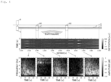
Fig. 4] Fig. 4 is a diagram showing a specific example of an optical communication underground facility position contrast processing of a first embodiment. - [
Fig. 5] Fig. 5 is a diagram showing a procedure of an optical communication underground facility position contrast processing of a second embodiment. - [
Fig. 6] Fig. 6 is a diagram showing a specific example of an optical communication underground facility position contrast processing of a second embodiment. - Embodiments of the present disclosure will be described with reference to the accompanying drawings. The embodiments described below are examples of the present disclosure, and the present disclosure is not limited to the following embodiments.
- (Configuration of the optical communication underground facility position contrast system of the present disclosure) The configuration of the optical communication underground facility position contrast system of the present disclosure is shown in
Fig. 2 . The underground facility position contrast system S includes the scattered light intensitydistribution measurement device 1 and the underground facilityposition contrast device 2. The underground facilityposition contrast device 2 includes the scattered light intensity distribution acquisition unit 21, the distortion responsedistribution measurement unit 22, and the underground facilityposition contrast unit 23. The underground facilityposition contrast device 2 can be realized by installing an underground facility position contrast program (which can be recorded on a recording medium, and also provided on a network) that is shown inFig. 3 and/orFig. 5 into a computer. - The scattered light intensity
distribution measurement device 1 measures, when an earthquake vibration is applied to the optical fiber F laid underground, a change over time in a scattered light intensity distribution in the longitudinal direction of the optical fiber F. The scattered light intensity distribution acquisition unit 21 acquires, when the earthquake vibration is applied to the optical fiber F laid underground, information of the change over time in the scattered light intensity distribution in the longitudinal direction of the optical fiber F. - The distortion response
distribution measurement unit 22 measures a change over time in a distortion response distribution in the longitudinal direction of the optical fiber F based on the change over time in the scattered light intensity distribution in the longitudinal direction of the optical fiber F by using an optical time domain back scattering measuring method or the like. The underground facilityposition contrast unit 23 estimates an underground facility state of the optical fiber F based on the change over time in the distortion response distribution in the longitudinal direction of the optical fiber F, associates the underground facility position of the optical fiber F with a longitudinal distance of the optical fiber F, and notifies the optical communication aggregation building B. - Thus, since the intentional impact applied to the lid of the manhole M is not utilized but the earthquake vibration applied to the optical fiber F is utilized, the human operation rate can be reduced in associating the underground facility position of the optical fiber F with the longitudinal distance of the optical fiber F.
- The procedure of the optical communication underground facility position contrast processing of the first embodiment is shown in
Fig. 3 . The scattered light intensity distribution acquisition unit 21 acquires, when the earthquake vibration is applied to the optical fiber F laid underground, information of the change over time in the scattered light intensity distribution in the longitudinal direction of the optical fiber F (step S1). The distortion responsedistribution measurement unit 22 measures the change over time in the vibration frequency distribution in the longitudinal direction of the optical fiber F based on the change over time in the scattered light intensity distribution in the longitudinal direction of the optical fiber F (step S2). - Then, the underground facility
position contrast unit 23 estimates, based on whether the change over time in the vibration frequency distribution in the longitudinal direction of the optical fiber F is continuous or discontinuous on the longitudinal distance of the optical fiber F (step S3), the underground facility state of the optical fiber F (step S4, S5), and associates the underground facility position of the optical fiber F with the longitudinal distance of the optical fiber F (step S6) . - Alternatively, the underground facility
position contrast unit 23 estimates, based on whether the change over time in the vibration frequency distribution in the longitudinal direction of the optical fiber F coincides with or differs from the change over time in the vibration frequency of the earthquake vibration (step S3), the underground facility state of the optical fiber F (step S4, S5), and associates the underground facility position of the optical fiber F with the longitudinal distance of the optical fiber F (step S6). - The specific example of the optical communication underground facility position contrast processing of the first embodiment is shown in
Fig. 4 . The optical fiber F is, in being laid under the ground G, laid within the conduit T, connected by the closure C under the manhole M1, and passes under the manhole M2 without using the closure C. - In the periphery of the vicinity of the longitudinal distances 1320 m, 1380 m and 1460 m or the like of the optical fiber F, the change over time in the vibration frequency of the optical fiber F shows vibration attenuation of about 10 seconds at a high frequency of about 10 Hz and shows vibration continuation of about 30 seconds at a low frequency of about 1 Hz. That is, the change over time in the vibration frequency distribution in the longitudinal direction of the optical fiber F is continuous on the longitudinal distance of the optical fiber F (step S3, YES). Alternatively, the change over time in the vibration frequency distribution in the longitudinal direction of the optical fiber F coincides with the change over time in the vibration frequency of the earthquake vibration (step S3, YES). This is because the optical fiber F is in contact with the ground G through the conduit T.
- Then, the underground facility
position contrast unit 23 estimates that the underground facility state of the optical fiber F is the section of the conduit T in the periphery of the vicinity of the longitudinal distances 1320 m, 1380 m, and 1460 m or the like of the optical fiber F (step S5), and can associate the position of the conduit T with the periphery of the vicinity of the longitudinal distances 1320 m, 1380 m, and 1460 m or the like of the optical fiber F (step S6). - Only in the vicinity of the longitudinal distance 1340 m of the optical fiber F, the change over time in the vibration frequency of the optical fiber F shows about 30 seconds of vibration continuation at a high frequency of about 10 Hz and does not show the vibration itself at a low frequency of about 1 Hz. Only in the vicinity of the longitudinal distance 1420 m of the optical fiber F, the change over time in the vibration frequency of the optical fiber F does not show the vibration itself at a high frequency of about 10 Hz and shows a vibration delay of about 30 seconds at a low frequency of about 1 Hz. That is, the change over time in the vibration frequency distribution in the longitudinal direction of the optical fiber F is discontinuous on the longitudinal distance of the optical fiber F (step S3, NO). Alternatively, the change over time in the vibration frequency distribution in the longitudinal direction of the optical fiber F does not coincide with the change over time in the vibration frequency of the earthquake vibration (step S3, NO). This is because the optical fiber F is not in contact with the ground G within the manholes M1, M2.
- Then, the underground facility
position contrast unit 23 estimates that the underground facility state of the optical fiber F is the section of the manhole M1 in which the closure C exists only in the vicinity of the longitudinal distance 1340 m of the optical fiber F (step S4), and can associate the position of the manhole M1 in which the closure C exists with the vicinity of the longitudinal distance 1340 m of the optical fiber F (step S6). The underground facilityposition contrast unit 23 estimates that the underground facility state of the optical fiber F is the section of the manhole M2 through which the optical fiber F passes only in the vicinity of the longitudinal distance 1420 m of the optical fiber F (step S4), and can associate the position of the manhole M2 through which the optical fiber F passes with the vicinity of the longitudinal distance 1420 m of the optical fiber F (step S6) . - In this way, the positions of the sections of the manholes M1, M2 and the section of the conduit T or the like can be associated with the longitudinal distance of the optical fiber F based on whether the change over time in the vibration frequency distribution in the longitudinal direction of the optical fiber F is continuous or discontinuous on the longitudinal distance of the optical fiber F.
- On the other hand, the positions of the sections of the manholes M1, M2 and the section of the conduit T or the like can be associated with the longitudinal distance of the optical fiber F based on whether the change over time in the vibration frequency distribution in the longitudinal direction of the optical fiber F coincides with or differs from the change over time in the vibration frequency of the earthquake vibration.
- The procedure of the optical communication underground facility position contrast processing of the second embodiment is shown in
Fig. 5 . The scattered light intensity distribution acquisition unit 21 acquires, when the earthquake vibration is applied to the optical fiber F laid underground, information of the change over time in the scattered light intensity distribution in the longitudinal direction of the optical fiber F (step S11). The distortion responsedistribution measurement unit 22 measures the change over time in the distortion amplitude distribution in the longitudinal direction of the optical fiber F based on the change over time in the scattered light intensity distribution in the longitudinal direction of the optical fiber F (step S12). - Then, the underground facility
position contrast unit 23 estimates, based on whether the change over time in the distortion amplitude distribution in the longitudinal direction of the optical fiber F is continuous or discontinuous on the longitudinal distance of the optical fiber F (step S13), the underground facility state of the optical fiber F (step S14, S15), and associates the underground facility position of the optical fiber F with the longitudinal distance of the optical fiber F (step S16). - A specific example of the optical communication underground facility position contrast processing of the second embodiment is shown in
Fig. 6 . The optical fiber F is, in being laid under the ground G, laid within the conduit T, connected by the closure C under the manhole M1, and passes under the manhole M2 without using the closure C. - In the middle stage of
Fig. 6 , the change over time in the distortion amplitude distribution in the longitudinal direction of the optical fiber F is shown within the range of 100 nε to -100 nε with the color scale of the distortion amplitude being set to the full scale. In the lower stage ofFig. 6 , the change over time in the distortion amplitude distribution in the longitudinal direction of the optical fiber F is shown within the range of 5 nε to -5 nε with the color scale of the distortion amplitude being set to the enlarged scale. - In the periphery of the vicinity of the longitudinal distances 1320 m, 1380 m and 1460 m or the like of the optical fiber F, the change over time in the distortion amplitude distribution in the longitudinal direction of the optical fiber F is continuous on the longitudinal distance of the optical fiber F (step S13, YES). This is because the optical fiber F is in contact with the ground G through the conduit T. In the periphery of the vicinity of the longitudinal distance 1440 m of the optical fiber F, the change over time in the distortion amplitude distribution in the longitudinal direction of the optical fiber F is continuous on the longitudinal distance of the optical fiber F (step S13, YES), but has a smaller distortion amplitude. This is because the optical fiber F does not come into close contact with the conduit T and is weak in contact with the ground G.
- Then, the underground facility
position contrast unit 23 estimates that the underground facility state of the optical fiber F is the section of the conduit T in the periphery of the vicinity of the longitudinal distances 1320 m, 1380 m, and 1460 m or the like of the optical fiber F (step S15), and can associate the position of the conduit T with the periphery of the vicinity of the longitudinal distances 1320 m, 1380 m, and 1460 m or the like of the optical fiber F (step S16). Then, the underground facilityposition contrast unit 23 estimates that the underground facility state of the optical fiber F is the section of the conduit T with which the optical fiber F does not come into close contact in the periphery of the vicinity of the longitudinal distance 1440 m of the optical fiber F (step S15), and can associate the position of the conduit T with which the optical fiber F does not come into close contact with the periphery of the vicinity of the longitudinal distance 1440 m of the optical fiber F (step S16) . - Only in the vicinity of the longitudinal distance 1340 m of the optical fiber F, the change over time in the distortion amplitude distribution in the longitudinal direction of the optical fiber F is discontinuous on the longitudinal distance of the optical fiber F, and has a high-frequency distortion amplitude (step S13, NO). This is because the optical fiber F is not in contact with the ground G and connected by closure C within the manhole M1. Only in the vicinity of the longitudinal distance 1420 m of the optical fiber F, the change over time in the distortion amplitude distribution in the longitudinal direction of the optical fiber F is discontinuous on the longitudinal distance of the optical fiber F, and hardly has distortion amplitude (step S13, NO). This is because the optical fiber F is not in contact with the ground G and only passes without using the closure C within the manhole M2.
- Then, the underground facility
position contrast unit 23 estimates that the underground facility state of the optical fiber F is the section of the manhole M1 in which the closure C exists only in the vicinity of the longitudinal distance 1340 m of the optical fiber F (step S14), and can associate the position of the manhole M1 in which the closure C exists with the vicinity of the longitudinal distance 1340 m of the optical fiber F (step S16). The underground facilityposition contrast unit 23 estimates that the underground facility state of the optical fiber F is the section of the manhole M2 through which the optical fiber F passes only in the vicinity of the longitudinal distance 1420 m of the optical fiber F (step S14), and can associate the position of the manhole M2 through which the optical fiber F passes with the vicinity of the longitudinal distance 1420 m of the optical fiber F (step S16) . - In this way, the positions of the sections of the manholes M1, M2 and the section of the conduit T or the like can be associated with the longitudinal distance of the optical fiber F based on whether the change over time in the distortion amplitude distribution in the longitudinal direction of the optical fiber F is continuous or discontinuous on the longitudinal distance of the optical fiber F.
- The optical communication underground facility position contrast system, the method for optical communication underground facility position contrast, and the optical communication underground facility position contrast device of the present disclosure can reduce the human operation rate by using the earthquake vibration in associating the underground facility position of the optical fiber with the longitudinal distance of the optical fiber.
-
- S:
- Underground facility position contrast system
- F:
- Optical fiber
- B:
- Optical communication aggregation building
- G:
- Ground
- M, M1, M2:
- Manhole
- C:
- Closure
- T:
- Conduit
- 1:
- Scattered light intensity distribution measurement device
- 2:
- Underground facility position contrast device
- 21:
- Scattered light intensity distribution acquisition unit
- 22:
- Distortion response distribution measurement unit
- 23:
- Underground facility position contrast unit
Claims (6)
- An optical communication underground facility position contrast system, comprising:a scattered light intensity distribution measurement device for measuring, when an earthquake vibration is applied to an optical fiber laid underground, a change over time in a scattered light intensity distribution in a longitudinal direction of the optical fiber; andan underground facility position contrast device for measuring a change over time in a distortion response distribution in the longitudinal direction of the optical fiber based on the change over time in the scattered light intensity distribution in the longitudinal direction of the optical fiber, estimating an underground facility state of the optical fiber based on the change over time in the distortion response distribution in the longitudinal direction of the optical fiber, and associating the underground facility position of the optical fiber with a longitudinal distance of the optical fiber.
- The optical communication underground facility position contrast system according to claim 1, wherein the underground facility position contrast device measures a change over time in a vibration frequency distribution in the longitudinal direction of the optical fiber based on the change over time in the scattered light intensity distribution in the longitudinal direction of the optical fiber, estimates an underground facility state of the optical fiber based on whether the change over time in the vibration frequency distribution in the longitudinal direction of the optical fiber is continuous or discontinuous on a longitudinal distance of the optical fiber, and associates the underground facility position of the optical fiber with the longitudinal distance of the optical fiber.
- The optical communication underground facility position contrast system according to claim 1 or 2, wherein the underground facility position contrast device measures a change over time in a vibration frequency distribution in the longitudinal direction of the optical fiber based on the change over time in the scattered light intensity distribution in the longitudinal direction of the optical fiber, estimates an underground facility state of the optical fiber based on whether the change over time in the vibration frequency distribution in the longitudinal direction of the optical fiber coincides with or differs from the change over time in the vibration frequency of the earthquake vibration, and associates the underground facility position of the optical fiber with the longitudinal distance of the optical fiber.
- The optical communication underground facility position contrast system according to any one of claims 1 to 3, wherein
the underground facility position contrast device measures a change over time in a distortion amplitude distribution in the longitudinal direction of the optical fiber based on the change over time in the scattered light intensity distribution in the longitudinal direction of the optical fiber, estimates an underground facility state of the optical fiber based on whether the change over time in the distortion amplitude distribution in the longitudinal direction of the optical fiber is continuous or discontinuous on a longitudinal distance of the optical fiber, and associates the underground facility position of the optical fiber with the longitudinal distance of the optical fiber. - A method for optical communication underground facility position contrast, comprising the sequential steps of:acquiring, when an earthquake vibration is applied to an optical fiber laid underground, information of a change over time in a scattered light intensity distribution in a longitudinal direction of the optical fiber;measuring a change over time in a distortion response distribution in the longitudinal direction of the optical fiber based on the change over time in the scattered light intensity distribution in the longitudinal direction of the optical fiber; andestimating an underground facility state of the optical fiber based on the change over time in the distortion response distribution in a longitudinal direction of the optical fiber, andassociating the underground facility position of the optical fiber with a longitudinal distance of the optical fiber.
- An optical communication underground facility position contrast device, comprising:a scattered light intensity distribution acquisition unit for acquiring, when an earthquake vibration is applied to an optical fiber laid underground, information of a change over time in a scattered light intensity distribution in a longitudinal direction of the optical fiber;a distortion response distribution measurement unit for measuring a change over time in a distortion response distribution in the longitudinal direction of the optical fiber based on the change over time in the scattered light intensity distribution in the longitudinal direction of the optical fiber; andan underground facility position contrast unit for estimating an underground facility state of the optical fiber based on the change over time in the distortion response distribution in the longitudinal direction of the optical fiber, and associating the underground facility position of the optical fiber with a longitudinal distance of the optical fiber.
Applications Claiming Priority (1)
| Application Number | Priority Date | Filing Date | Title |
|---|---|---|---|
| PCT/JP2021/029938 WO2023021562A1 (en) | 2021-08-16 | 2021-08-16 | Optical communication underground equipment location reference system, optical communication underground equipment location reference method, and optical communication underground equipment location reference device |
Publications (3)
| Publication Number | Publication Date |
|---|---|
| EP4390302A1 true EP4390302A1 (en) | 2024-06-26 |
| EP4390302A4 EP4390302A4 (en) | 2025-06-25 |
| EP4390302B1 EP4390302B1 (en) | 2026-01-28 |
Family
ID=85240223
Family Applications (1)
| Application Number | Title | Priority Date | Filing Date |
|---|---|---|---|
| EP21954137.2A Active EP4390302B1 (en) | 2021-08-16 | 2021-08-16 | Optical communication underground equipment location reference system, optical communication underground equipment location reference method, and optical communication underground equipment location reference device |
Country Status (4)
| Country | Link |
|---|---|
| US (1) | US12674902B2 (en) |
| EP (1) | EP4390302B1 (en) |
| JP (1) | JP7652265B2 (en) |
| WO (1) | WO2023021562A1 (en) |
Family Cites Families (4)
| Publication number | Priority date | Publication date | Assignee | Title |
|---|---|---|---|---|
| JP2020186911A (en) * | 2017-07-28 | 2020-11-19 | 長野計器株式会社 | Sewerage monitoring system and construction method thereof |
| JP7077610B2 (en) * | 2017-12-26 | 2022-05-31 | 日本電気株式会社 | Monitoring device, monitoring method, program |
| JP6974747B2 (en) * | 2018-09-20 | 2021-12-01 | 日本電信電話株式会社 | Manhole position identification method and manhole position identification system |
| CN114127519A (en) * | 2019-07-16 | 2022-03-01 | 日本电气株式会社 | Fiber optic sensing system, fiber optic sensing device and method for detecting degradation of a conduit |
-
2021
- 2021-08-16 US US18/682,522 patent/US12674902B2/en active Active
- 2021-08-16 JP JP2023542051A patent/JP7652265B2/en active Active
- 2021-08-16 WO PCT/JP2021/029938 patent/WO2023021562A1/en not_active Ceased
- 2021-08-16 EP EP21954137.2A patent/EP4390302B1/en active Active
Also Published As
| Publication number | Publication date |
|---|---|
| CN117716202A (en) | 2024-03-15 |
| JP7652265B2 (en) | 2025-03-27 |
| US20250123415A1 (en) | 2025-04-17 |
| EP4390302A4 (en) | 2025-06-25 |
| WO2023021562A1 (en) | 2023-02-23 |
| US12674902B2 (en) | 2026-07-07 |
| EP4390302B1 (en) | 2026-01-28 |
| JPWO2023021562A1 (en) | 2023-02-23 |
Similar Documents
| Publication | Publication Date | Title |
|---|---|---|
| US20200200526A1 (en) | Method and system for determining whether an event has occurred from dynamic strain measurements | |
| US10852209B2 (en) | Water leak sensing system and method | |
| EP3892963A1 (en) | Road monitoring system, road monitoring device, road monitoring method, and non-transitory computer-readable medium | |
| EP2902764A1 (en) | Defect analysis device, defect analysis method, and program | |
| EP4296633A1 (en) | Utility pole position specification method and aerial fiber optic cable state estimation method | |
| EP4001863A1 (en) | Optical fiber sensing system, optical fiber sensing device, and method for detecting pipe deterioration | |
| US8013987B2 (en) | Method and apparatus for fiber optic signature recognition | |
| JP2024540489A (en) | Impulse signal detection for buried cable protection using distributed optical fiber sensing | |
| Martins et al. | Early detection of pipeline integrity threats using a smart fiber optic surveillance system: the PIT-STOP project | |
| AU2015277149A1 (en) | Cathodic protection management system | |
| CN212565339U (en) | Natural gas long distance pipeline safety precaution system | |
| US20240003738A1 (en) | Position specifying system, vibration generator, and position specifying method | |
| EP4390302B1 (en) | Optical communication underground equipment location reference system, optical communication underground equipment location reference method, and optical communication underground equipment location reference device | |
| Yamada et al. | Limitation of the predominant-period estimator for earthquake early warning and the initial rupture of earthquakes | |
| US8358120B2 (en) | Non-intrusive detection of live electrical lines | |
| US20230228384A1 (en) | Detection device and detection method | |
| US6353320B1 (en) | Conveyance locating system and method for multiple conveyances on the same right-of-way | |
| US12292325B2 (en) | Detection system, detection device, and detection method | |
| CN105136802A (en) | Health assessment pre-warning system for oil and gas pipelines | |
| KR20230005626A (en) | Method for detecting hazardous level of construction event and apparatus thereof | |
| CN103968257B (en) | Pipeline monitoring system based on meshing optical fiber sensor and method of pipeline monitoring system | |
| US5994904A (en) | Method and apparatus for monitoring the relative position of a cable boring head during a boring operation | |
| JP2003279389A (en) | Safety measures for underground pipes | |
| CN105654698A (en) | Method for realizing remote centralized metering through serial server | |
| KR20220101293A (en) | Apparatus, method and system for identifying construction work causing vibration to optical cable |
Legal Events
| Date | Code | Title | Description |
|---|---|---|---|
| STAA | Information on the status of an ep patent application or granted ep patent |
Free format text: STATUS: THE INTERNATIONAL PUBLICATION HAS BEEN MADE |
|
| PUAI | Public reference made under article 153(3) epc to a published international application that has entered the european phase |
Free format text: ORIGINAL CODE: 0009012 |
|
| STAA | Information on the status of an ep patent application or granted ep patent |
Free format text: STATUS: REQUEST FOR EXAMINATION WAS MADE |
|
| 17P | Request for examination filed |
Effective date: 20240124 |
|
| AK | Designated contracting states |
Kind code of ref document: A1 Designated state(s): AL AT BE BG CH CY CZ DE DK EE ES FI FR GB GR HR HU IE IS IT LI LT LU LV MC MK MT NL NO PL PT RO RS SE SI SK SM TR |
|
| DAV | Request for validation of the european patent (deleted) | ||
| DAX | Request for extension of the european patent (deleted) | ||
| A4 | Supplementary search report drawn up and despatched |
Effective date: 20250522 |
|
| RIC1 | Information provided on ipc code assigned before grant |
Ipc: G01M 11/00 20060101ALI20250516BHEP Ipc: G01B 11/16 20060101AFI20250516BHEP |
|
| RAP3 | Party data changed (applicant data changed or rights of an application transferred) |
Owner name: NTT, INC. |
|
| GRAP | Despatch of communication of intention to grant a patent |
Free format text: ORIGINAL CODE: EPIDOSNIGR1 |
|
| STAA | Information on the status of an ep patent application or granted ep patent |
Free format text: STATUS: GRANT OF PATENT IS INTENDED |
|
| INTG | Intention to grant announced |
Effective date: 20251106 |
|
| GRAS | Grant fee paid |
Free format text: ORIGINAL CODE: EPIDOSNIGR3 |
|
| GRAA | (expected) grant |
Free format text: ORIGINAL CODE: 0009210 |
|
| STAA | Information on the status of an ep patent application or granted ep patent |
Free format text: STATUS: THE PATENT HAS BEEN GRANTED |
|
| AK | Designated contracting states |
Kind code of ref document: B1 Designated state(s): AL AT BE BG CH CY CZ DE DK EE ES FI FR GB GR HR HU IE IS IT LI LT LU LV MC MK MT NL NO PL PT RO RS SE SI SK SM TR |
|
| REG | Reference to a national code |
Ref country code: CH Ref legal event code: F10 Free format text: ST27 STATUS EVENT CODE: U-0-0-F10-F00 (AS PROVIDED BY THE NATIONAL OFFICE) Effective date: 20260128 Ref country code: GB Ref legal event code: FG4D |
|
| REG | Reference to a national code |
Ref country code: DE Ref legal event code: R096 Ref document number: 602021047442 Country of ref document: DE |
|
| REG | Reference to a national code |
Ref country code: IE Ref legal event code: FG4D |
|
| REG | Reference to a national code |
Ref country code: NL Ref legal event code: MP Effective date: 20260128 |
|
| PG25 | Lapsed in a contracting state [announced via postgrant information from national office to epo] |
Ref country code: NL Free format text: LAPSE BECAUSE OF FAILURE TO SUBMIT A TRANSLATION OF THE DESCRIPTION OR TO PAY THE FEE WITHIN THE PRESCRIBED TIME-LIMIT Effective date: 20260128 |
|
| REG | Reference to a national code |
Ref country code: AT Ref legal event code: MK05 Ref document number: 1881756 Country of ref document: AT Kind code of ref document: T Effective date: 20260128 |
|
| PG25 | Lapsed in a contracting state [announced via postgrant information from national office to epo] |
Ref country code: RS Free format text: LAPSE BECAUSE OF FAILURE TO SUBMIT A TRANSLATION OF THE DESCRIPTION OR TO PAY THE FEE WITHIN THE PRESCRIBED TIME-LIMIT Effective date: 20260428 |
|
| PG25 | Lapsed in a contracting state [announced via postgrant information from national office to epo] |
Ref country code: ES Free format text: LAPSE BECAUSE OF FAILURE TO SUBMIT A TRANSLATION OF THE DESCRIPTION OR TO PAY THE FEE WITHIN THE PRESCRIBED TIME-LIMIT Effective date: 20260128 |
|
| PG25 | Lapsed in a contracting state [announced via postgrant information from national office to epo] |
Ref country code: PL Free format text: LAPSE BECAUSE OF FAILURE TO SUBMIT A TRANSLATION OF THE DESCRIPTION OR TO PAY THE FEE WITHIN THE PRESCRIBED TIME-LIMIT Effective date: 20260128 |
|
| PG25 | Lapsed in a contracting state [announced via postgrant information from national office to epo] |
Ref country code: GR Free format text: LAPSE BECAUSE OF FAILURE TO SUBMIT A TRANSLATION OF THE DESCRIPTION OR TO PAY THE FEE WITHIN THE PRESCRIBED TIME-LIMIT Effective date: 20260429 |
|
| REG | Reference to a national code |
Ref country code: LT Ref legal event code: MG9D |
|
| PG25 | Lapsed in a contracting state [announced via postgrant information from national office to epo] |
Ref country code: LT Free format text: LAPSE BECAUSE OF FAILURE TO SUBMIT A TRANSLATION OF THE DESCRIPTION OR TO PAY THE FEE WITHIN THE PRESCRIBED TIME-LIMIT Effective date: 20260128 |
|
| PG25 | Lapsed in a contracting state [announced via postgrant information from national office to epo] |
Ref country code: NO Free format text: LAPSE BECAUSE OF FAILURE TO SUBMIT A TRANSLATION OF THE DESCRIPTION OR TO PAY THE FEE WITHIN THE PRESCRIBED TIME-LIMIT Effective date: 20260428 |
|
| PG25 | Lapsed in a contracting state [announced via postgrant information from national office to epo] |
Ref country code: AT Free format text: LAPSE BECAUSE OF FAILURE TO SUBMIT A TRANSLATION OF THE DESCRIPTION OR TO PAY THE FEE WITHIN THE PRESCRIBED TIME-LIMIT Effective date: 20260128 Ref country code: FI Free format text: LAPSE BECAUSE OF FAILURE TO SUBMIT A TRANSLATION OF THE DESCRIPTION OR TO PAY THE FEE WITHIN THE PRESCRIBED TIME-LIMIT Effective date: 20260128 Ref country code: SE Free format text: LAPSE BECAUSE OF FAILURE TO SUBMIT A TRANSLATION OF THE DESCRIPTION OR TO PAY THE FEE WITHIN THE PRESCRIBED TIME-LIMIT Effective date: 20260128 |
|
| PG25 | Lapsed in a contracting state [announced via postgrant information from national office to epo] |
Ref country code: HR Free format text: LAPSE BECAUSE OF FAILURE TO SUBMIT A TRANSLATION OF THE DESCRIPTION OR TO PAY THE FEE WITHIN THE PRESCRIBED TIME-LIMIT Effective date: 20260128 |
|
| PG25 | Lapsed in a contracting state [announced via postgrant information from national office to epo] |
Ref country code: IS Free format text: LAPSE BECAUSE OF FAILURE TO SUBMIT A TRANSLATION OF THE DESCRIPTION OR TO PAY THE FEE WITHIN THE PRESCRIBED TIME-LIMIT Effective date: 20260528 Ref country code: PT Free format text: LAPSE BECAUSE OF FAILURE TO SUBMIT A TRANSLATION OF THE DESCRIPTION OR TO PAY THE FEE WITHIN THE PRESCRIBED TIME-LIMIT Effective date: 20260528 |
|
| PG25 | Lapsed in a contracting state [announced via postgrant information from national office to epo] |
Ref country code: LV Free format text: LAPSE BECAUSE OF FAILURE TO SUBMIT A TRANSLATION OF THE DESCRIPTION OR TO PAY THE FEE WITHIN THE PRESCRIBED TIME-LIMIT Effective date: 20260128 |
|
| PG25 | Lapsed in a contracting state [announced via postgrant information from national office to epo] |
Ref country code: BG Free format text: LAPSE BECAUSE OF FAILURE TO SUBMIT A TRANSLATION OF THE DESCRIPTION OR TO PAY THE FEE WITHIN THE PRESCRIBED TIME-LIMIT Effective date: 20260128 |