EP4390295A1 - Heat exchanger with longitudinal baffle and dual operating method thereof - Google Patents
Heat exchanger with longitudinal baffle and dual operating method thereof Download PDFInfo
- Publication number
- EP4390295A1 EP4390295A1 EP23020451.3A EP23020451A EP4390295A1 EP 4390295 A1 EP4390295 A1 EP 4390295A1 EP 23020451 A EP23020451 A EP 23020451A EP 4390295 A1 EP4390295 A1 EP 4390295A1
- Authority
- EP
- European Patent Office
- Prior art keywords
- shell
- tube
- heat exchanger
- fluid
- heat
- Prior art date
- Legal status (The legal status is an assumption and is not a legal conclusion. Google has not performed a legal analysis and makes no representation as to the accuracy of the status listed.)
- Withdrawn
Links
Images


Classifications
-
- F—MECHANICAL ENGINEERING; LIGHTING; HEATING; WEAPONS; BLASTING
- F28—HEAT EXCHANGE IN GENERAL
- F28D—HEAT-EXCHANGE APPARATUS, NOT PROVIDED FOR IN ANOTHER SUBCLASS, IN WHICH THE HEAT-EXCHANGE MEDIA DO NOT COME INTO DIRECT CONTACT
- F28D7/00—Heat-exchange apparatus having stationary tubular conduit assemblies for both heat-exchange media, the media being in contact with different sides of a conduit wall
- F28D7/16—Heat-exchange apparatus having stationary tubular conduit assemblies for both heat-exchange media, the media being in contact with different sides of a conduit wall the conduits being arranged in parallel spaced relation
-
- F—MECHANICAL ENGINEERING; LIGHTING; HEATING; WEAPONS; BLASTING
- F28—HEAT EXCHANGE IN GENERAL
- F28D—HEAT-EXCHANGE APPARATUS, NOT PROVIDED FOR IN ANOTHER SUBCLASS, IN WHICH THE HEAT-EXCHANGE MEDIA DO NOT COME INTO DIRECT CONTACT
- F28D7/00—Heat-exchange apparatus having stationary tubular conduit assemblies for both heat-exchange media, the media being in contact with different sides of a conduit wall
- F28D7/16—Heat-exchange apparatus having stationary tubular conduit assemblies for both heat-exchange media, the media being in contact with different sides of a conduit wall the conduits being arranged in parallel spaced relation
- F28D7/1607—Heat-exchange apparatus having stationary tubular conduit assemblies for both heat-exchange media, the media being in contact with different sides of a conduit wall the conduits being arranged in parallel spaced relation with particular pattern of flow of the heat exchange media, e.g. change of flow direction
-
- F—MECHANICAL ENGINEERING; LIGHTING; HEATING; WEAPONS; BLASTING
- F28—HEAT EXCHANGE IN GENERAL
- F28F—DETAILS OF HEAT-EXCHANGE AND HEAT-TRANSFER APPARATUS, OF GENERAL APPLICATION
- F28F9/00—Casings; Header boxes; Auxiliary supports for elements; Auxiliary members within casings
- F28F9/22—Arrangements for directing heat-exchange media into successive compartments, e.g. arrangements of guide plates
- F28F2009/222—Particular guide plates, baffles or deflectors, e.g. having particular orientation relative to an elongated casing or conduit
- F28F2009/224—Longitudinal partitions
-
- F—MECHANICAL ENGINEERING; LIGHTING; HEATING; WEAPONS; BLASTING
- F28—HEAT EXCHANGE IN GENERAL
- F28F—DETAILS OF HEAT-EXCHANGE AND HEAT-TRANSFER APPARATUS, OF GENERAL APPLICATION
- F28F9/00—Casings; Header boxes; Auxiliary supports for elements; Auxiliary members within casings
- F28F9/22—Arrangements for directing heat-exchange media into successive compartments, e.g. arrangements of guide plates
- F28F2009/222—Particular guide plates, baffles or deflectors, e.g. having particular orientation relative to an elongated casing or conduit
- F28F2009/226—Transversal partitions
Definitions
- the present invention refers to a shell-and-tube heat exchanger, substantially with cylindrical geometry. More specifically, the present invention refers to a heat exchanger with straight exchanging tubes and two tube-sheets.
- the heat exchanger object of the present invention realizes an indirect and counter-current heat exchange between the tube-side fluid and the shell-side fluid, and is characterized by a number of shell-side passes higher than the number of tube-side passes.
- Heat exchangers for treating heavy hydrocarbons to produce gasoline, sulfur condensers installed in Claus plants and transfer-line heat exchangers installed on hydrocarbons cracking furnaces for ethylene production are examples of heat exchangers where the tube-side process fluid is fouled and presents a possible two-phase regime, and where inlet and outlet temperatures on shell-side are comparable to those on tube-side (possible temperatures cross).
- a purpose of the present invention is to provide a new heat exchanger configuration that simultaneously exhibits the mentioned features.
- Another purpose of the present invention is to provide a heat exchanger, along with its operating method, able to work in dual mode and, specifically, as a boiler and as a boiler feedwater preheater.
- a heat exchanger can be installed on hydrocarbons cracking furnaces (ethylene production).
- the patent document No. CN202692763 which represents the prior-art document closest to the present invention, describes a shell-and-tube heat exchanger with straight tubes, two tube-sheets and longitudinal baffles designed to flow the shell-side fluid according to several passes across the shell. In other words, the longitudinal baffles separate the shell into several zones.
- the patent document No. CN202692763 clearly describes that:
- the present invention therefore intends to provide a heat exchanger where the longitudinal baffles have a constrained end and a free end, and where at least one shell-side zone delimited by the longitudinal baffles is not crossed by the tube-bundle.
- the present invention also intends to provide a heat exchanger where the longitudinal baffles are cylindrical, forming an annular shell-side zone not crossed by the tube-bundle.
- the heat exchanger object of the present invention is configured to achieve an indirect heat exchange between the tube-side fluid and the shell-side fluid as follows:
- the heat exchanger object of the present invention is configured to achieve an indirect heat exchange between the tube-side fluid and the shell-side fluid as follows:
- the heat exchanger comprises at least a pair of longitudinal baffles installed in the shell delimiting at least one shell-side zone not crossed by the tube-bundle.
- the longitudinal baffles covered by this invention may correspond to sheets of plane or cylindrical shape;
- the tube-layout basically corresponds to circular segments, whereas in the second case the tube-layout presents a central circular zone and an outer crown, i.e. a substantially axial-symmetric tube-layout.
- the longitudinal baffles object of the present invention have one end connected to a tube-sheet and the other end free and open to allow the passage of the shell-side fluid.
- the free end also has the important function to:
- the heat exchanger object of the present invention offers superior thermo-mechanical performance as the axial-symmetrical tube-layout of the exchanging tubes allows eliminating the shear stresses in the tube-sheet due to temperature differences that arise in the tube-sheet.
- the present invention also discloses a heat exchanger configuration that can be used in dual mode, i.e. in a first mode according to which the shell-side fluid mainly exchanges sensible heat and in a second mode according to which the shell-side fluid mainly exchanges latent heat.
- the heat exchanger object of the present invention works according to the first mode as a heater or cooler of the shell-side fluid, and according to the second mode as a boiler or vaporizer of the shell-side fluid.
- the present invention discloses a transfer-line heat exchanger installed on hydrocarbons cracking furnaces for the production of ethylene capable of working in dual mode, i.e. as a boiler feedwater preheater with forced circulation on shell-side and as a boiler with natural or assisted circulation on shell-side.
- the heat exchanger operating according to a dual mode can also be used as a process gas boiler/cooler installed downstream of chemical reactors.
- the present invention therefore, also describes the operating method for operating the heat exchanger disclosed here according to a dual mode.
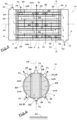
- Fig.1 schematically shows the longitudinal and lateral view of the heat exchanger (1a) according to a preferred configuration of the present invention.
- the heat exchanger (1a) shown in Fig.1 has a substantially cylindrical geometry and is of shell-and-tube type.
- the heat exchanger (1a) comprises straight exchanging tubes (3), extended along the longitudinal axis (12) of the heat exchanger (1a), with ends connected to bores of a first and a second tube-sheet (4,5).
- the heat exchanger (1a) also comprises a shell (2) enveloping the tube-bundle and connected to the two tube-sheets (4,5), a first tube-side distributor (6) connected to the first tube-sheet (4) on the side opposite the tube-bundle, a second tube-side distributor (7) connected to the second tube-sheet (5) on the side opposite the tube-bundle, tube-side inlet and outlet connections (10,11) installed respectively on the first and second distributor (6,7), shell-side inlet and outlet connections (8,9) installed on the shell (2) near the second (5) and the first (4) tube-sheet respectively.
- the distributors (6,7) and the heat exchanging tubes (3) are each other in fluid communication.
- the heat exchanger (1a) of Fig.1 also comprises two longitudinal baffles (13,14), of substantially cylindrical geometry, installed in the shell (2).
- the cylindrical longitudinal baffles (13,14) extend along the longitudinal axis (12) of the heat exchanger (1a); preferably, the cylindrical longitudinal baffles (13,14) extend almost the entire length of the exchanging tubes (3).
- the cylindrical longitudinal baffles (13,14) are arranged concentrically relative to each other and the shell (2).
- the first cylindrical longitudinal baffle (13) is innermost, has the first end (15) connected to the second tube-sheet (5) and the second end (16) open and free, i.e. not connected to the first tube-sheet (4).
- the second cylindrical longitudinal baffle (14) is outermost, having the first end (17) connected to the first tube-sheet (4) and the second end (18) open and free, i.e. not connected to the second tube-sheet (5).
- the cylindrical longitudinal baffles (13,14) are installed in the shell (2) in such a way that adjacent baffles have the open and free ends longitudinally opposite.
- the longitudinal cylindrical baffles (13,14) delimit the shell (2) in three substantially concentric zones ( 19 , 20 , 21 ) and, specifically, in a first heat exchanging zone ( 19 ) delimited by the first longitudinal baffle (13) and crossed by a first portion of the tube-bundle, in a conveying zone (20 ) essentially annular in shape and delimited by the two longitudinal cylindrical baffles (13,14) and not crossed by the tube-bundle, and in a second heat exchanging zone ( 21 ) delimited by the second longitudinal baffle (14) and the shell (2) and crossed by a second portion of the tube-bundle.
- first and second heat exchanging zones ( 19 , 21 ) diaphragms or transversal baffles are installed (22,23) to realize a tortuous shell-side flow path and to support the exchanging tubes (3); preferably, the transversal baffles (22,23) are of disc-doughnut type.
- the first heat exchanging zone ( 19 ) is in fluid communication with the inlet shell-side connection (8) and with the conveying zone ( 20 ) at the open and free end (16) of the first cylindrical longitudinal baffle (13).
- the first heat exchanging zone ( 19 ) and the conveying zone ( 20 ) are in fluid communication because the first cylindrical longitudinal baffle (13) is detached from the first tube-sheet (4).
- the second heat exchanging zone ( 21 ) communicates with the outlet shell-side connection (9) and with the conveying zone ( 20 ) at the open and free end (18) of the second cylindrical longitudinal baffle (14).
- the second heat exchanging zone ( 21 ) and the conveying zone ( 20 ) are in fluid communication because the second cylindrical longitudinal baffle (14) is detached from the second tube-sheet (5).
- the first and second cylindrical longitudinal baffle (13,14) are connected respectively to the second and first tube-sheet (4,5) in a substantially tight manner.
- the shell-side fluid (F1) is introduced into the first heat exchanging zone ( 19 ), near the second tube-sheet (5), through the inlet shell-side connection (8).
- the shell-side fluid (F1) flows towards the first tube-sheet (4) through the first heat exchanging zone ( 19 ) indirectly exchanging heat with the tube-side fluid (F2), arrives at the open and free end (16) of the first cylindrical longitudinal baffle (13) and enters the conveying zone ( 20 ).
- the shell-side fluid (F1) flows towards the second tube-sheet (5) through the conveying zone ( 20 ) without exchanging heat with the tube-side fluid (F2), arrives at the open and free end (18) of the second cylindrical longitudinal baffle (14) and enters the second heat exchanging zone ( 21 ) and flows towards the first tube-sheet (4) through the second heat exchanging zone (21) indirectly exchanging heat with the tube-side fluid (F2).
- the shell-side fluid (F1) is extracted from the second heat exchanging zone ( 21 ), near the first tube-sheet (4), by means of the shell-side outlet connection (9).
- the tube-side fluid (F2) is fed into the heat exchanger (1a) via the inlet tube-side connection (10) and is extracted from the heat exchanger (1a) via the outlet tube-side connection (11).
- the tube-side fluid (F2) is distributed in the exchanging tubes (3) through the first distributor (6), flows from the first tube-sheet (4) to the second tube-sheet (5) inside the exchanging tubes (3) indirectly exchanging heat with the shell-side fluid (F1), and is collected from the exchanging tubes (3) through the second distributor (7).
- Fig.2 shows the sectional view (X-X') of the heat exchanger (1a) shown in Fig.1 .
- the tube-layout of the exchanging tubes (3) is axial-symmetrical.
- the central circular zone of the tube-bundle corresponds to the first heat exchanging zone ( 19 ) and is surrounded by an annular space without exchanging tubes (3) corresponding to the conveying zone ( 20 ), while the peripheral zone of the tube-bundle, comparable to a circular crown, corresponds to the second heat exchanging zone ( 21 ).
- the inlet shell-side connection (8) is provided with an internal duct (35) joining the connection to the first cylindrical longitudinal baffle (13).
- the internal duct (35) does not intersect the second cylindrical longitudinal baffle (14); in other words, the second cylindrical longitudinal baffle (14) has the open and free second end (18) shaped or positioned at a distance from the second tube-sheet (5) in such a way that it is not intersected by the internal duct (35).
- the heat exchanger (1a) object of the present invention is characterized by the fact that:
- Fig.3 schematically shows the longitudinal and lateral view of the heat exchanger (1b) according to a preferred configuration of the present invention.
- the heat exchanger (1b) of Fig.3 is structurally equivalent to that of Fig. 1 except for the longitudinal baffles, the tube-layout and the transversal baffles of the tube-bundle; in other words, the elements and construction details, and their numbering, of the heat exchanger (1b) shown in Fig.3 are equivalent to those of the heat exchanger (1a) shown in Fig. 1 , except for longitudinal baffles, tube-layout and transversal baffles. Therefore, for convenience, the description of the heat exchanger (1b) of Fig.3 is partially omitted.
- the heat exchanger (1b) of Fig.3 comprises two pairs of longitudinal baffles (24a,25a,24b,25b), of substantially plane geometry, installed in the shell (2).
- the plane longitudinal baffles (24a,25a,24b,25b) extend along the longitudinal axis (12) of the heat exchanger (1b); preferably, the plane longitudinal baffles (24a,25a,24b,25B) extend almost the entire length of the exchanging tubes (3).
- the plane longitudinal baffles (24a,25a,24b,25b) are arranged parallel to each other.
- the first and third plane longitudinal baffle (24a,24b) have the first end (26) connected to the second tube-sheet (5) and the second end (27) free and open.
- the second and fourth plane longitudinal baffle (25a,25b) have the first end (28) connected to the first tube-sheet (4) and the second end (29) free and open.
- the plane longitudinal baffles (24a,25a,24b,25b) are installed in the shell (2) so that the adjacent baffles have the free ends longitudinally opposite.
- the plane longitudinal baffles (24a,25a,24b,25b) delimit the shell (2) into five zones ( 30 , 31 , 32 , 33 , 34 ) adjacent to each other and, specifically, in a first, a second and a third heat exchanging zone ( 30 , 32 , 34 ) and in a first and a second conveying zone ( 31 , 33 ).
- the heat exchanging zones ( 30 , 32 , 34 ) and the conveying zones ( 31 , 33 ) alternate so that two adjacent heat exchanging zones ( 30 , 32 , 34 ) are separated from each other by a conveying zone ( 31 , 33 ).
- the three_heat exchanging zones ( 30 , 32 , 34 ) are crossed by portions of the tube-bundle and therefore are place of heat exchange between the shell-side fluid (F1) and the tube-side fluid (F2), whereas the conveying zones ( 31 , 33 ) are not crossed by the exchanging tubes (3) and therefore are not place of heat exchange.
- the transversal baffles (38) are of single- or double-segment type.
- the first heat exchanging zone ( 30 ) is in fluid communication with the inlet shell-side connection (8), located near the second tube-sheet (5), and with the first conveying zone ( 31 ) at the free end (27) of the first plane longitudinal baffle (24a).
- the second heat exchanging zone ( 32 ) is in fluid communication with the first conveying zone ( 31 ) at the free end (29) of the second plane longitudinal baffle (25a) and with the second conveying zone ( 33 ) at the free end (27) of the third plane longitudinal baffle (24b).
- the third heat exchanging zone ( 34 ) is in fluid communication with the outlet shell-side connection (9), located near the first tube-sheet (4), and with the second conveying zone ( 33 ) at the free end (29) of the fourth plane longitudinal baffle (25b).
- the heat exchanging zones ( 30 , 32 , 34 ) are in communication with the conveying zones ( 31 , 33 ) as the plane longitudinal baffles (24a,25a,24b,25b) have a free and open end (27,29) detached from the tube-sheets (4,5).
- the shell-side fluid (F1) is introduced into the first heat exchanging zone ( 30 ), near the second tube-sheet (5), through the inlet shell-side connection (8).
- the shell-side fluid (F1) flows towards the first tube-sheet (4) through the first heat exchanging zone ( 30 ) indirectly exchanging heat with the tube-side fluid (F2), reaches the free end (27) of the first plane longitudinal baffle (24a) and enters the first conveying zone ( 31 ).
- the shell-side fluid (F1) flows towards the second tube-sheet (5) through the first conveying zone ( 31 ) without exchanging heat with the tube-side fluid (F2), arrives at the free end (29) of the second plane longitudinal baffle (25a) and enters the second heat exchanging zone ( 32 ).
- the shell-side fluid (F1) flows towards the first tube-sheet (4) through the second heat exchanging zone ( 32 ) indirectly exchanging heat with the tube-side fluid (F2), reaches the free end (27) of the third plane longitudinal baffle (24b) and enters the second conveying zone ( 33 ).
- the shell-side fluid (F1) flows towards the second tube-sheet (5) through the second conveying zone ( 33 ) without exchanging heat with the tube-side fluid (F2), arrives at the free end (29) of the fourth plane longitudinal baffle (25b) and enters the third heat exchanging zone ( 34 ).
- the shell-side fluid (F1) flows towards the first tube-sheet (4) through the third heat exchanging zone (34) indirectly exchanging heat with the tube-side fluid (F2) and exits the third heat exchanging zone ( 34 ), near the first tube-sheet (4), through the shell-side outlet connection (9).
- the tube-side fluid (F2) is fed into the heat exchanger (1b) through the tube-side inlet connection (10) installed on the first distributor (6) and is extracted from the heat exchanger (1b) through the tube-side outlet connection (11) installed on the second distributor (7).
- the tube-side fluid (F2) is distributed in the exchanging tubes (3) through the first distributor (6), flows from the first tube-sheet (4) to the second tube-sheet (5) inside the exchanging tubes (3) indirectly exchanging heat with the shell-side fluid (F1), and is collected from the exchanging tubes (3) through the second distributor (7).
- Fig.4 shows the sectional view (Y-Y') of the heat exchanger (1b) shown in Fig.3 .
- the tube-layout of the exchanging tubes (3) is divided into three circular segments, corresponding to the three heat exchanging zones ( 30 , 32 , 34 ), separated by the two conveying zones ( 31 , 33 ).
- the two conveying zones ( 31 , 33 ) are delimited by the plane longitudinal baffles (24a,25a,24b,25b).
- the heat exchanger (1b) object of the present invention is characterized by the fact that:
- Fig.5 schematically shows the longitudinal and top view of the heat exchanger (1c) according to a preferred configuration of the present invention.
- the heat exchanger (1c) of Fig.5 is structurally equivalent to that of Fig.3 except for the shell-side inlet and outlet connections; in other words, the elements and construction details, and the relative numbering, of the heat exchanger (1c) shown in Fig.5 are equivalent to those of the heat exchanger (1b) shown in Fig.3 , except for the shell-side connections. So, for convenience, the description of the heat exchanger (1c) of Fig.5 is partially omitted.
- the heat exchanger (1c) shown in Fig.5 has the longitudinal axis (12) parallel or quasi- parallel to the ground and the plane longitudinal baffles (24a,25a,24b,25b) installed in a vertical position, i.e. orthogonal to the ground.
- the heat exchanger (1c) comprises a first inlet shell-side connection (8a) positioned near the second tube-sheet (5) and in fluid communication with the first heat exchanging zone (30) and three second inlet shell-side connections (8b) each in fluid communication with one of the heat exchanging zones ( 30 , 32 , 34 );
- the heat exchanger (1c) comprises a first outlet shell-side connection (9a) positioned near the first tube-sheet (4) and in fluid communication with the third heat exchanging zone ( 34 ) and three second shell-side outlet connections (9b) each in fluid communication with one of the heat exchanging zones ( 30 , 32 , 34 ).
- the first and the second shell-side inlet connections (8a,8b) are shown with dashed lines in Fig.5 as they are positioned on the lower part of the shell (2), whereas the first and the second shell-side outlet connections (9a,9b) are positioned on the upper part of the shell (2).
- the heat exchanger (1c) is equipped with additional second shell-side inlet connections (8b) installed on the lower part of the shell (2); according to another preferred configuration, the heat exchanger (1c) is equipped with additional second shell-side outlet connections (9b) installed on the upper part of the shell (2).
- at least a portion of the second shell-side outlet connections (9b) are positioned near the first tube-sheet (4) or near the tube-side fluid inlet distributor (F2).
- Fig.6 shows the sectional view (Z-Z') of the heat exchanger (1c) shown in Fig.5 .
- the tube-layout of the exchanging tubes (3) is divided into three circular segments, corresponding to the three heat exchanging zones ( 30 , 32 , 34 ), separated by the two conveying zones ( 31 , 33 ).
- the two conveying zones ( 31 , 33 ) are delimited by the plane longitudinal baffles (24a,25a,24b,25b), positioned orthogonally to the ground (36).
- the heat exchanger (1c) shown in Fig.5 and Fig.6 object of this invention is configured to operate in dual mode:
- the operating method essentially corresponds to that described for the heat exchanger (1b) of Fig.3 .
- Some inlet and outlet shell-side connections of the heat exchanger (1c) of Fig.5 are open and the other connections are closed by devices, such as valves, not shown in the figure. More specifically, the first inlet shell-side connection (8a), close to the second tube-sheet (5) and in fluid communication with the first heat exchanging zone, ( 30 ) and the first shell-side outlet connection (9a), close to the first tube-sheet (4) and in fluid communication with the third heat exchanging zone ( 34 ), are open; contrarily, the second shell-side inlet and outletconnections (8b,9b) are closed.
- the shell-side fluid (F1) is introduced into the first heat exchanging zone ( 30 ) through the first inlet shell-side connection (8a), flows through the three heat exchanging zones ( 30 , 32 , 34 ) mainly exchanging sensible heat with the tube-side fluid (F2) and the two conveyng zones ( 31 , 33 ) without exchanging heat with the tube-side fluid (F2), and is extracted from the third heat exchanging zone ( 34 ) by the first outlet shell-side connection (9a).
- the two fluids (F1,F2) are contacted in pure counter-current, the tube-side fluid (F2) has one pass and the shell-side fluid (F1) has five passes, two of them without heat exchange.
- the second inlet and outlet shell-side connections(8b,9b) are open; the first inlet shell-side connection (8a), close to the second tube-sheet (5) and in fluid communication with the first heat exchanging zone (30), and/or the first shell-side outlet connection (9a), close to the first tube-sheet (4) and in fluid communication with the third heat exchanging zone ( 34 ), can be closed or opened.
- the first shell-side inlet and outlet connections (8a,9a) are closed.
- the shell-side fluid (F1) essentially in liquid phase, is introduced into the shell (2) through the second inlet shell-side connections (8b) or through the second inlet shell-side connections (8b) and the first inlet shell-side connection (8a).
- the shell-side fluid (F1) moves mainly in the longitudinal direction to be distributed in the heat exchanging zones ( 30 , 32 , 34 ) and in the conveying zones ( 31 , 33 ).
- the shell-side fluid (F1) moves mainly upwards by crossing the exchanging tubes (3) and vaporizing.
- the shell-side fluid (F1) in liquid and vapor phase, moves mainly in the longitudinal direction to collect and exit the shell (2).
- the shell-side fluid (F 1) in liquid and vapor phase, exits the shell (2) by means of the second shell-side outlet connections (9b) or by the second shell-side outlet connections (9b) and the first shell-side outlet connection (9a).
- the shell-side fluid (F1) circulates in the shell (2) preferably according to natural or assisted circulation, and therefore the flow of the shell-side fluid is globally ascending.
- the second inlet and outlet shell-side connections (8b,9b) are installed respectively in the lower and upper part of the shell (2) to facilitate the upward flow and the vapor release.
- the two fluids (F1,F2) are contacted substantially in cross-flow, i.e. the tube-side fluid (F2) has one pass from tube-sheet to tube-sheet and the shell-side fluid (F 1) basically has a pass from bottom to top.
- the transversal baffles (38) have openings (not shown in the figure) at the lower and upper part of the heat exchanging zones ( 30 , 32 , 34 ) to ease respectively the distribution of the shell-side fluid (F1) in liquid phase in the lower part and the collection of the shell-side fluid (F1) in liquid and vapor phase in the upper part.
- the conveying zones ( 31 , 33 ) are provided with vents (not shown in the figures) on the upper part of the shell to remove possible vapor fractions.
- the heat exchanger (1c) related to Fig.5 and Fig.6 can be used as an transfer-line heat exchanger for hydrocarbons cracking furnaces, for the production of ethylene, and in particular can be used as a transfer-line heat exchanger (1c) operating in dual mode.
- High-temperature cracked gas is flowed on tube-side and needs to be cooled.
- On shell-side high-pressure boiling water is flowed.
- the shell-side of the transfer-line heat exchanger (1c) is hydraulically connected, by piping, to an elevated steam drum (not shown in the figures); more specifically, the first and the second inlet and outlet shell-side connections (8a,9a,8b,9b), or a portion of them, are connected to the steam drum by means of piping.
- the piping are preferably equipped with valves to close or open the boiler water (F1) passage according to the operating mode of the transfer-line heat exchanger (1c).
- the transfer-line heat exchanger (1c) can operate as a boiler or preheater according to the operating principles described for Fig.5 and Fig.6 , summarized below and adapted to the specific service:
- one or more longitudinal baffles (13,14,24a,25a,24b,25b) can be formed by two juxtaposed sheets forming a small cavity in between; in other words, a longitudinal baffle (13,14,24a,25a,24b,25b) covered by the present invention can have a sandwich configuration.
- the cavity has a size of about 4 ⁇ 12mm.
- the cavity and the shell (2) are each other in fluid communication through openings such as to prevent the shell-side fluid (F1) from circulating in the cavity during the operation of the heat exchanger (1a, 1b, 1c); in other words, the shell-side fluid (F 1) in the cavity is essentially stagnant.
- the cavity is useful to limit or avoid the shell-side heat exchange between adjacent zones of the tube-bundle, and therefore to increase the overall heat exchange efficiency.
- fluids (F1,F2) can be flowed into the heat exchanger (1a,1b) also as follows:
- fluids (F1,F2) can be flowed into the heat exchanger (1c) also as follows:
- the present invention achieves the scope to provide a heat exchanger (1a,1b,1c) configured so to operate with a single pass of the tube-side fluid, several passes of the shell-side fluid and the two fluids contacted in a pure counter-current configuration.
- the present invention also achieves the scope to provide a heat exchanger (1c) configured to operate in dual mode, i.e. a first mode according to which the shell-side fluid vaporizes and flows with natural circulation from bottom to top, and a second mode according to which the shell-side fluid moving in forced convection is heated or cooled. More specifically, the present invention also achieves the scope to provide an transfer-line heat exchanger (1c), installed on cracking furnaces to produce ethylene, operating in dual mode, as a boiler and as a boiler feedwater preheater.
- the heat exchanger object of the present invention is subject in any case to numerous modifications and variants, all attributable to the same inventive concept.
- all details can be replaced with technically equivalent elements.
- building materials, shapes and sizes can be of any type according to technical requirements.
Landscapes
- Engineering & Computer Science (AREA)
- Physics & Mathematics (AREA)
- Thermal Sciences (AREA)
- Mechanical Engineering (AREA)
- General Engineering & Computer Science (AREA)
- Heat-Exchange Devices With Radiators And Conduit Assemblies (AREA)
Abstract
Shell-and-tube heat exchanger with substantially cylindrical geometry and straight exchanging tubes, apt to indirectly exchange heat between a shell-side fluid and a tube-side fluid contacted in pure counter-current and with a number of shell-side passes larger than the number of tube-side passes.The heat exchanger comprises shell-side longitudinal baffles, plane or cylindrical in shape, having one end open and free longitudinally opposite and delimiting different shell-side zones crossed and not crossed by the tube-bundle.Heat exchanger configured to operate in dual mode and, in particular, as a boiler when the shell-side fluid mainly exchanges latent heat and as a heater or cooler when the shell-side fluid mainly exchanges sensible heat.
Description
- The present invention refers to a shell-and-tube heat exchanger, substantially with cylindrical geometry. More specifically, the present invention refers to a heat exchanger with straight exchanging tubes and two tube-sheets.
- The heat exchanger object of the present invention realizes an indirect and counter-current heat exchange between the tube-side fluid and the shell-side fluid, and is characterized by a number of shell-side passes higher than the number of tube-side passes.
- With reference to the shell-and-tube heat exchangers, in general:
- straight exchanging tubes are used when there are significant fouling coefficients on the tube-side such as to require mechanical cleaning of the exchanging tubes;
- a single tube-side pass, with straight tubes, is preferred when the tube-side fluid has limited allowable pressure drops and/or when it has two-phase conditions;
- a multi-pass shell-side configuration is preferred when the shell-side fluid velocity has to be increased and when allowable shell-side pressure drops are generous;
- a counter-current configuration is preferred because the heat exchange efficiency is higher and because, if the temperatures of the two fluids present a cross, the temperatures cross can be controlled.
- Heat exchangers for treating heavy hydrocarbons to produce gasoline, sulfur condensers installed in Claus plants and transfer-line heat exchangers installed on hydrocarbons cracking furnaces for ethylene production are examples of heat exchangers where the tube-side process fluid is fouled and presents a possible two-phase regime, and where inlet and outlet temperatures on shell-side are comparable to those on tube-side (possible temperatures cross).
- Another application that usually requires straight tubes, single tube-side pass and possibly several shell-side passes is represented by vertical tubular chemical reactors with catalyst loaded into the tubes.
- The design of a shell-and-tube heat exchanger where following features coexist:
- Straight tubes,
- Single pass on tube-side,
- Multi-pass on shell-side,
- Pure counter-current heat exchange,
- Thus, a purpose of the present invention is to provide a new heat exchanger configuration that simultaneously exhibits the mentioned features.
- Another purpose of the present invention is to provide a heat exchanger, along with its operating method, able to work in dual mode and, specifically, as a boiler and as a boiler feedwater preheater. Such a heat exchanger can be installed on hydrocarbons cracking furnaces (ethylene production).
- In the literature there are numerous solutions for shell-and-tube heat exchangers with straight tubes and multi-pass on shell-side.
- The patent document No.
CN202692763 , which represents the prior-art document closest to the present invention, describes a shell-and-tube heat exchanger with straight tubes, two tube-sheets and longitudinal baffles designed to flow the shell-side fluid according to several passes across the shell. In other words, the longitudinal baffles separate the shell into several zones. The patent document No.CN202692763 clearly describes that: - the longitudinal baffles completely extend from tube-sheet to tube-sheet or from tube-sheet to transversal baffle and are provided with openings to connect adjacent shell-side zones;
- The shell-side zones are all crossed by the exchanging tubes.
- The exchanger disclosed by patent document No.
CN202692763 , therefore, presents a couple of critical technical characteristics: - 1) Since longitudinal baffles have both their ends connected to the tube-sheets or transversal baffles, potential problems about hydraulic sealing and thermal expansion can arise, as well as difficulties in manufacturing the tube-bundle;
- 2) Since all the shell-side zones are crossed by the tubes, it is not possible to carry out a pure counter-current heat exchange if the number of tube-side passes is different from the number of shell-side passes.
- To remove the potential problems of the mentioned prior-art heat exchanger, the present invention therefore intends to provide a heat exchanger where the longitudinal baffles have a constrained end and a free end, and where at least one shell-side zone delimited by the longitudinal baffles is not crossed by the tube-bundle. The present invention also intends to provide a heat exchanger where the longitudinal baffles are cylindrical, forming an annular shell-side zone not crossed by the tube-bundle.
- The patent document No.
US2017/205147A1 describes another possible configuration of heat exchanger with straight tubes and shell-side longitudinal baffles. - The heat exchanger object of the present invention, of shell-and-tube type with straight exchanging tubes and two tube-sheets, is configured to achieve an indirect heat exchange between the tube-side fluid and the shell-side fluid as follows:
- by a counter-current configuration;
- by a number of shell-side passes greater than the number of tube-side passes.
- More specifically, the heat exchanger object of the present invention is configured to achieve an indirect heat exchange between the tube-side fluid and the shell-side fluid as follows:
- with fluids contacted only in pure counter-current;
- by a single pass on tube-side;
- by several passes on shell- side.
- To execute the required heat exchange, the heat exchanger comprises at least a pair of longitudinal baffles installed in the shell delimiting at least one shell-side zone not crossed by the tube-bundle.
- The longitudinal baffles covered by this invention may correspond to sheets of plane or cylindrical shape; In the first case, the tube-layout basically corresponds to circular segments, whereas in the second case the tube-layout presents a central circular zone and an outer crown, i.e. a substantially axial-symmetric tube-layout.
- The longitudinal baffles object of the present invention have one end connected to a tube-sheet and the other end free and open to allow the passage of the shell-side fluid. The free end also has the important function to:
- ease the construction of the tube-bundle;
- eliminate constraints related to thermal expansion of baffles;
- eliminate any problems related to the hydraulic seal of the baffles on the tube-sheet.
- In the case of longitudinal baffles with cylindrical geometry, the heat exchanger object of the present invention offers superior thermo-mechanical performance as the axial-symmetrical tube-layout of the exchanging tubes allows eliminating the shear stresses in the tube-sheet due to temperature differences that arise in the tube-sheet.
- The present invention also discloses a heat exchanger configuration that can be used in dual mode, i.e. in a first mode according to which the shell-side fluid mainly exchanges sensible heat and in a second mode according to which the shell-side fluid mainly exchanges latent heat. The heat exchanger object of the present invention works according to the first mode as a heater or cooler of the shell-side fluid, and according to the second mode as a boiler or vaporizer of the shell-side fluid.
- More specifically, the present invention discloses a transfer-line heat exchanger installed on hydrocarbons cracking furnaces for the production of ethylene capable of working in dual mode, i.e. as a boiler feedwater preheater with forced circulation on shell-side and as a boiler with natural or assisted circulation on shell-side. The heat exchanger operating according to a dual mode can also be used as a process gas boiler/cooler installed downstream of chemical reactors.
- The present invention, therefore, also describes the operating method for operating the heat exchanger disclosed here according to a dual mode.
- For the detailed description of the heat exchanger object of this invention, following figures are reported:
-
Fig. 1 , where the longitudinal and lateral view of the heat exchanger with cylindrical longitudinal baffles is schematically shown according to a preferred configuration of the present invention; -
Fig.2 , where a cross-sectional view of the heat exchanger with longitudinal cylindrical baffles is schematically shown according to a preferred configuration of the present invention; -
Fig.3 , where the longitudinal and lateral view of the heat exchanger with plane longitudinal baffles is schematically shown according to a preferred configuration of the present invention; -
Fig.4 , where the cross-sectional view of the heat exchanger with plane longitudinal baffles is schematically shown according to a preferred configuration of the present invention; -
Fig.5 , where the longitudinal and top view of the heat exchanger with plane longitudinal baffles is schematically shown according to a preferred configuration of the present invention; -
Fig.6 , where the cross-sectional view of the heat exchanger with plane longitudinal baffles is schematically shown according to a preferred configuration of the present invention. -
Fig.1 schematically shows the longitudinal and lateral view of the heat exchanger (1a) according to a preferred configuration of the present invention. - The heat exchanger (1a) shown in
Fig.1 has a substantially cylindrical geometry and is of shell-and-tube type. The heat exchanger (1a) comprises straight exchanging tubes (3), extended along the longitudinal axis (12) of the heat exchanger (1a), with ends connected to bores of a first and a second tube-sheet (4,5). The heat exchanger (1a) also comprises a shell (2) enveloping the tube-bundle and connected to the two tube-sheets (4,5), a first tube-side distributor (6) connected to the first tube-sheet (4) on the side opposite the tube-bundle, a second tube-side distributor (7) connected to the second tube-sheet (5) on the side opposite the tube-bundle, tube-side inlet and outlet connections (10,11) installed respectively on the first and second distributor (6,7), shell-side inlet and outlet connections (8,9) installed on the shell (2) near the second (5) and the first (4) tube-sheet respectively. The distributors (6,7) and the heat exchanging tubes (3) are each other in fluid communication. - The heat exchanger (1a) of
Fig.1 also comprises two longitudinal baffles (13,14), of substantially cylindrical geometry, installed in the shell (2). The cylindrical longitudinal baffles (13,14) extend along the longitudinal axis (12) of the heat exchanger (1a); preferably, the cylindrical longitudinal baffles (13,14) extend almost the entire length of the exchanging tubes (3). The cylindrical longitudinal baffles (13,14) are arranged concentrically relative to each other and the shell (2). The first cylindrical longitudinal baffle (13) is innermost, has the first end (15) connected to the second tube-sheet (5) and the second end (16) open and free, i.e. not connected to the first tube-sheet (4). The second cylindrical longitudinal baffle (14) is outermost, having the first end (17) connected to the first tube-sheet (4) and the second end (18) open and free, i.e. not connected to the second tube-sheet (5). In other words, the cylindrical longitudinal baffles (13,14) are installed in the shell (2) in such a way that adjacent baffles have the open and free ends longitudinally opposite. The longitudinal cylindrical baffles (13,14) delimit the shell (2) in three substantially concentric zones (19,20,21) and, specifically, in a first heat exchanging zone (19) delimited by the first longitudinal baffle (13) and crossed by a first portion of the tube-bundle, in a conveying zone (20) essentially annular in shape and delimited by the two longitudinal cylindrical baffles (13,14) and not crossed by the tube-bundle, and in a second heat exchanging zone (21) delimited by the second longitudinal baffle (14) and the shell (2) and crossed by a second portion of the tube-bundle. In the first and second heat exchanging zones (19,21) diaphragms or transversal baffles are installed (22,23) to realize a tortuous shell-side flow path and to support the exchanging tubes (3); preferably, the transversal baffles (22,23) are of disc-doughnut type. The first heat exchanging zone (19) is in fluid communication with the inlet shell-side connection (8) and with the conveying zone (20) at the open and free end (16) of the first cylindrical longitudinal baffle (13). In other words, the first heat exchanging zone (19) and the conveying zone (20) are in fluid communication because the first cylindrical longitudinal baffle (13) is detached from the first tube-sheet (4). The second heat exchanging zone (21) communicates with the outlet shell-side connection (9) and with the conveying zone (20) at the open and free end (18) of the second cylindrical longitudinal baffle (14). In other words, the second heat exchanging zone (21) and the conveying zone (20) are in fluid communication because the second cylindrical longitudinal baffle (14) is detached from the second tube-sheet (5). The first and second cylindrical longitudinal baffle (13,14) are connected respectively to the second and first tube-sheet (4,5) in a substantially tight manner. - According to
Fig.1 , the shell-side fluid (F1) is introduced into the first heat exchanging zone (19), near the second tube-sheet (5), through the inlet shell-side connection (8). The shell-side fluid (F1) flows towards the first tube-sheet (4) through the first heat exchanging zone (19) indirectly exchanging heat with the tube-side fluid (F2), arrives at the open and free end (16) of the first cylindrical longitudinal baffle (13) and enters the conveying zone (20). The shell-side fluid (F1) flows towards the second tube-sheet (5) through the conveying zone (20) without exchanging heat with the tube-side fluid (F2), arrives at the open and free end (18) of the second cylindrical longitudinal baffle (14) and enters the second heat exchanging zone (21) and flows towards the first tube-sheet (4) through the second heat exchanging zone (21) indirectly exchanging heat with the tube-side fluid (F2). The shell-side fluid (F1) is extracted from the second heat exchanging zone (21), near the first tube-sheet (4), by means of the shell-side outlet connection (9). The tube-side fluid (F2) is fed into the heat exchanger (1a) via the inlet tube-side connection (10) and is extracted from the heat exchanger (1a) via the outlet tube-side connection (11). The tube-side fluid (F2) is distributed in the exchanging tubes (3) through the first distributor (6), flows from the first tube-sheet (4) to the second tube-sheet (5) inside the exchanging tubes (3) indirectly exchanging heat with the shell-side fluid (F1), and is collected from the exchanging tubes (3) through the second distributor (7). -
Fig.2 shows the sectional view (X-X') of the heat exchanger (1a) shown inFig.1 . Basically, the tube-layout of the exchanging tubes (3) is axial-symmetrical. The central circular zone of the tube-bundle corresponds to the first heat exchanging zone (19) and is surrounded by an annular space without exchanging tubes (3) corresponding to the conveying zone (20), while the peripheral zone of the tube-bundle, comparable to a circular crown, corresponds to the second heat exchanging zone (21). The inlet shell-side connection (8) is provided with an internal duct (35) joining the connection to the first cylindrical longitudinal baffle (13). Preferably, the internal duct (35) does not intersect the second cylindrical longitudinal baffle (14); in other words, the second cylindrical longitudinal baffle (14) has the open and free second end (18) shaped or positioned at a distance from the second tube-sheet (5) in such a way that it is not intersected by the internal duct (35). - According to
Fig. 1 and Fig.2 , the heat exchanger (1a) object of the present invention is characterized by the fact that: - the shell-side fluid (F1) performs three passes (19,20,21), where the pass relating to the conveying zone (20) takes place without heat exchange with the tube-side fluid (F2);
- The tube-side fluid (F2) makes one pass;
- The shell-side fluid (F1) and the tube-side fluid (F2) are indirectly contacted according to a pure counter-current configuration.
-
Fig.3 schematically shows the longitudinal and lateral view of the heat exchanger (1b) according to a preferred configuration of the present invention. - The heat exchanger (1b) of
Fig.3 is structurally equivalent to that ofFig. 1 except for the longitudinal baffles, the tube-layout and the transversal baffles of the tube-bundle; in other words, the elements and construction details, and their numbering, of the heat exchanger (1b) shown inFig.3 are equivalent to those of the heat exchanger (1a) shown inFig. 1 , except for longitudinal baffles, tube-layout and transversal baffles. Therefore, for convenience, the description of the heat exchanger (1b) ofFig.3 is partially omitted. - The heat exchanger (1b) of
Fig.3 comprises two pairs of longitudinal baffles (24a,25a,24b,25b), of substantially plane geometry, installed in the shell (2). The plane longitudinal baffles (24a,25a,24b,25b) extend along the longitudinal axis (12) of the heat exchanger (1b); preferably, the plane longitudinal baffles (24a,25a,24b,25B) extend almost the entire length of the exchanging tubes (3). The plane longitudinal baffles (24a,25a,24b,25b) are arranged parallel to each other. The first and third plane longitudinal baffle (24a,24b) have the first end (26) connected to the second tube-sheet (5) and the second end (27) free and open. The second and fourth plane longitudinal baffle (25a,25b) have the first end (28) connected to the first tube-sheet (4) and the second end (29) free and open. The plane longitudinal baffles (24a,25a,24b,25b) are installed in the shell (2) so that the adjacent baffles have the free ends longitudinally opposite. The plane longitudinal baffles (24a,25a,24b,25b) delimit the shell (2) into five zones (30,31,32,33,34) adjacent to each other and, specifically, in a first, a second and a third heat exchanging zone (30,32,34) and in a first and a second conveying zone (31,33). The heat exchanging zones (30,32,34) and the conveying zones (31,33) alternate so that two adjacent heat exchanging zones (30,32,34) are separated from each other by a conveying zone (31,33). The three_heat exchanging zones (30,32,34) are crossed by portions of the tube-bundle and therefore are place of heat exchange between the shell-side fluid (F1) and the tube-side fluid (F2), whereas the conveying zones (31,33) are not crossed by the exchanging tubes (3) and therefore are not place of heat exchange. In the three heat exchanging zones (30,32,34) diaphragms or transverse baffles (38)_are installed to make tortuous the shell-side flow and to support the exchanging tubes (3). Preferably, the transversal baffles (38) are of single- or double-segment type. - As shown in
Fig. 3 , the first heat exchanging zone (30) is in fluid communication with the inlet shell-side connection (8), located near the second tube-sheet (5), and with the first conveying zone (31) at the free end (27) of the first plane longitudinal baffle (24a). The second heat exchanging zone (32) is in fluid communication with the first conveying zone (31) at the free end (29) of the second plane longitudinal baffle (25a) and with the second conveying zone (33) at the free end (27) of the third plane longitudinal baffle (24b). The third heat exchanging zone (34) is in fluid communication with the outlet shell-side connection (9), located near the first tube-sheet (4), and with the second conveying zone (33) at the free end (29) of the fourth plane longitudinal baffle (25b). In other words, the heat exchanging zones (30,32,34) are in communication with the conveying zones (31,33) as the plane longitudinal baffles (24a,25a,24b,25b) have a free and open end (27,29) detached from the tube-sheets (4,5). - According to
Fig.3 , the shell-side fluid (F1) is introduced into the first heat exchanging zone (30), near the second tube-sheet (5), through the inlet shell-side connection (8). The shell-side fluid (F1) flows towards the first tube-sheet (4) through the first heat exchanging zone (30) indirectly exchanging heat with the tube-side fluid (F2), reaches the free end (27) of the first plane longitudinal baffle (24a) and enters the first conveying zone (31). The shell-side fluid (F1) flows towards the second tube-sheet (5) through the first conveying zone (31) without exchanging heat with the tube-side fluid (F2), arrives at the free end (29) of the second plane longitudinal baffle (25a) and enters the second heat exchanging zone (32). The shell-side fluid (F1) flows towards the first tube-sheet (4) through the second heat exchanging zone (32) indirectly exchanging heat with the tube-side fluid (F2), reaches the free end (27) of the third plane longitudinal baffle (24b) and enters the second conveying zone (33). The shell-side fluid (F1) flows towards the second tube-sheet (5) through the second conveying zone (33) without exchanging heat with the tube-side fluid (F2), arrives at the free end (29) of the fourth plane longitudinal baffle (25b) and enters the third heat exchanging zone (34). The shell-side fluid (F1) flows towards the first tube-sheet (4) through the third heat exchanging zone (34) indirectly exchanging heat with the tube-side fluid (F2) and exits the third heat exchanging zone (34), near the first tube-sheet (4), through the shell-side outlet connection (9). The tube-side fluid (F2) is fed into the heat exchanger (1b) through the tube-side inlet connection (10) installed on the first distributor (6) and is extracted from the heat exchanger (1b) through the tube-side outlet connection (11) installed on the second distributor (7). The tube-side fluid (F2) is distributed in the exchanging tubes (3) through the first distributor (6), flows from the first tube-sheet (4) to the second tube-sheet (5) inside the exchanging tubes (3) indirectly exchanging heat with the shell-side fluid (F1), and is collected from the exchanging tubes (3) through the second distributor (7). -
Fig.4 shows the sectional view (Y-Y') of the heat exchanger (1b) shown inFig.3 . Basically, the tube-layout of the exchanging tubes (3) is divided into three circular segments, corresponding to the three heat exchanging zones (30,32,34), separated by the two conveying zones (31,33). The two conveying zones (31,33) are delimited by the plane longitudinal baffles (24a,25a,24b,25b). - According to
Fig.3 and Fig.4 , the heat exchanger (1b) object of the present invention is characterized by the fact that: - the shell-side fluid (F1) performs five passes (30,31,32,33,34), where those relating to the conveying zones (31,33) take place without heat exchange with the tube-side fluid (F2);
- The tube-side fluid (F2) performs only one pass;
- The shell-side fluid (F1) and the tube-side fluid (F2) are indirectly contacted according to a pure counter-current configuration.
-
Fig.5 schematically shows the longitudinal and top view of the heat exchanger (1c) according to a preferred configuration of the present invention. - The heat exchanger (1c) of
Fig.5 is structurally equivalent to that ofFig.3 except for the shell-side inlet and outlet connections; in other words, the elements and construction details, and the relative numbering, of the heat exchanger (1c) shown inFig.5 are equivalent to those of the heat exchanger (1b) shown inFig.3 , except for the shell-side connections. So, for convenience, the description of the heat exchanger (1c) ofFig.5 is partially omitted. - The heat exchanger (1c) shown in
Fig.5 has the longitudinal axis (12) parallel or quasi- parallel to the ground and the plane longitudinal baffles (24a,25a,24b,25b) installed in a vertical position, i.e. orthogonal to the ground. The heat exchanger (1c) comprises a first inlet shell-side connection (8a) positioned near the second tube-sheet (5) and in fluid communication with the first heat exchanging zone (30) and three second inlet shell-side connections (8b) each in fluid communication with one of the heat exchanging zones (30, 32,34); The heat exchanger (1c) comprises a first outlet shell-side connection (9a) positioned near the first tube-sheet (4) and in fluid communication with the third heat exchanging zone (34) and three second shell-side outlet connections (9b) each in fluid communication with one of the heat exchanging zones (30, 32,34). The first and the second shell-side inlet connections (8a,8b) are shown with dashed lines inFig.5 as they are positioned on the lower part of the shell (2), whereas the first and the second shell-side outlet connections (9a,9b) are positioned on the upper part of the shell (2). According to another preferred configuration, the heat exchanger (1c) is equipped with additional second shell-side inlet connections (8b) installed on the lower part of the shell (2); according to another preferred configuration, the heat exchanger (1c) is equipped with additional second shell-side outlet connections (9b) installed on the upper part of the shell (2). According to another preferred configuration, at least a portion of the second shell-side outlet connections (9b) are positioned near the first tube-sheet (4) or near the tube-side fluid inlet distributor (F2). -
Fig.6 shows the sectional view (Z-Z') of the heat exchanger (1c) shown inFig.5 . Basically, the tube-layout of the exchanging tubes (3) is divided into three circular segments, corresponding to the three heat exchanging zones (30,32,34), separated by the two conveying zones (31,33). The two conveying zones (31,33) are delimited by the plane longitudinal baffles (24a,25a,24b,25b), positioned orthogonally to the ground (36). - The heat exchanger (1c) shown in
Fig.5 and Fig.6 object of this invention is configured to operate in dual mode: - As a boiler, with the shell-side fluid (F1) that vaporizes or exchanges mainly latent heat, and that circulates in the heat exchanger (1c) according to natural or assisted circulation;
- As a heater or cooler, with the shell-side fluid (F1) which is heated or cooled, or which is mainly exchanging sensible heat, and circulating in the heat exchanger (1c) according to forced convection.
- When the heat exchanger (1c) of
Fig.5 operates as a heater or cooler, the operating method essentially corresponds to that described for the heat exchanger (1b) ofFig.3 . Some inlet and outlet shell-side connections of the heat exchanger (1c) ofFig.5 are open and the other connections are closed by devices, such as valves, not shown in the figure. More specifically, the first inlet shell-side connection (8a), close to the second tube-sheet (5) and in fluid communication with the first heat exchanging zone, (30) and the first shell-side outlet connection (9a), close to the first tube-sheet (4) and in fluid communication with the third heat exchanging zone (34), are open; contrarily, the second shell-side inlet and outletconnections (8b,9b) are closed. Therefore, according to the operating method related toFig.3 , the shell-side fluid (F1) is introduced into the first heat exchanging zone (30) through the first inlet shell-side connection (8a), flows through the three heat exchanging zones (30,32,34) mainly exchanging sensible heat with the tube-side fluid (F2) and the two conveyng zones (31, 33) without exchanging heat with the tube-side fluid (F2), and is extracted from the third heat exchanging zone (34) by the first outlet shell-side connection (9a). When the heat exchanger (1c) is operated in heating or cooling mode, the two fluids (F1,F2) are contacted in pure counter-current, the tube-side fluid (F2) has one pass and the shell-side fluid (F1) has five passes, two of them without heat exchange. - When the heat exchanger (1c) of
Fig.5 operates as a boiler, the second inlet and outlet shell-side connections(8b,9b) are open; the first inlet shell-side connection (8a), close to the second tube-sheet (5) and in fluid communication with the first heat exchanging zone (30), and/or the first shell-side outlet connection (9a), close to the first tube-sheet (4) and in fluid communication with the third heat exchanging zone (34), can be closed or opened. According to a preferred configuration, the first shell-side inlet and outlet connections (8a,9a) are closed. The shell-side fluid (F1), essentially in liquid phase, is introduced into the shell (2) through the second inlet shell-side connections (8b) or through the second inlet shell-side connections (8b) and the first inlet shell-side connection (8a). In the lower part of the shell (2), the shell-side fluid (F1) moves mainly in the longitudinal direction to be distributed in the heat exchanging zones (30,32,34) and in the conveying zones (31,33). Subsequently, in the heat exchanging zones (30,32,34), the shell-side fluid (F1) moves mainly upwards by crossing the exchanging tubes (3) and vaporizing. In the upper part of the shell (2), the shell-side fluid (F1), in liquid and vapor phase, moves mainly in the longitudinal direction to collect and exit the shell (2). The shell-side fluid (F 1), in liquid and vapor phase, exits the shell (2) by means of the second shell-side outlet connections (9b) or by the second shell-side outlet connections (9b) and the first shell-side outlet connection (9a). The shell-side fluid (F1) circulates in the shell (2) preferably according to natural or assisted circulation, and therefore the flow of the shell-side fluid is globally ascending. The second inlet and outlet shell-side connections (8b,9b) are installed respectively in the lower and upper part of the shell (2) to facilitate the upward flow and the vapor release. When the heat exchanger (1c) is operated in boiler mode, the two fluids (F1,F2) are contacted substantially in cross-flow, i.e. the tube-side fluid (F2) has one pass from tube-sheet to tube-sheet and the shell-side fluid (F 1) basically has a pass from bottom to top. - According to a preferred configuration related to
Fig.5 and Fig.6 , the transversal baffles (38) have openings (not shown in the figure) at the lower and upper part of the heat exchanging zones (30,32,34) to ease respectively the distribution of the shell-side fluid (F1) in liquid phase in the lower part and the collection of the shell-side fluid (F1) in liquid and vapor phase in the upper part. - According to a preferred configuration related to
Fig.5 and Fig.6 , the conveying zones (31,33) are provided with vents (not shown in the figures) on the upper part of the shell to remove possible vapor fractions. - The heat exchanger (1c) related to
Fig.5 and Fig.6 can be used as an transfer-line heat exchanger for hydrocarbons cracking furnaces, for the production of ethylene, and in particular can be used as a transfer-line heat exchanger (1c) operating in dual mode. High-temperature cracked gas is flowed on tube-side and needs to be cooled. On shell-side, high-pressure boiling water is flowed. The shell-side of the transfer-line heat exchanger (1c) is hydraulically connected, by piping, to an elevated steam drum (not shown in the figures); more specifically, the first and the second inlet and outlet shell-side connections (8a,9a,8b,9b), or a portion of them, are connected to the steam drum by means of piping. The piping are preferably equipped with valves to close or open the boiler water (F1) passage according to the operating mode of the transfer-line heat exchanger (1c). Based on the characteristics of the cracked gas, and more specifically on the type of the hydrocarbons feedstock subjected to thermal cracking, the transfer-line heat exchanger (1c) can operate as a boiler or preheater according to the operating principles described forFig.5 and Fig.6 , summarized below and adapted to the specific service: - In boiler mode, the second inlet and outlet shell-side connections (8b,9b) are open; the first shell-side inlet connection (8a) and/or the first shell-side outlet connection (9a) can be opened or, preferably, closed. The boiler water (F1) coming from the steam drum is introduced in substantially liquid phase into the shell (2) by the second inlet shell-side connections (8b) or by the second inlet shell-side connections (8b) and the first inlet shell-side connection (8a). The boiler water (F1) is distributed in the shell (2), rises upwards by crossing the exchanging tubes (3), vaporizes, and exits in liquid and vapor phase through the second shell-side outlet connections (9b) or through the second shell-side outlet connections (9b) and the first shell-side outlet connection (9a). The boiler water (F1) exiting from the transfer-line heat exchanger (1c) rises towards the steam drum. The boiler water (F1) circulates between steam drum and transfer-line heat exchanger (1c) through the piping and by natural or assisted circulation.
- In preheater mode, the second inlet and outlet shell-side connections (8b,9b) are closed; the first shell-side inlet connection (8a) and the first shell-side outlet connection (9a) are open. The boiler water (F1) is introduced into the shell (2) in liquid phase through the first inlet shell-side connection (8a), runs through the three heat exchanging zones (30,32,34) where it preheats, and the two conveying zones (31,33), and is extracted from the shell (2), in substantially liquid phase or with a limited steam fraction, by means of the first outlet shell-side connection (9a). The boiler water (F1) circulates in the shell (2) by forced convection; the boiler water (F1) to be preheated comes from a third equipment (not shown in the figures), and the preheated boiler water (F1) is transported by a pipe from the transfer-line heat exchanger (1c) to the steam drum.
- According to a preferred configuration relating to the present invention, one or more longitudinal baffles (13,14,24a,25a,24b,25b) can be formed by two juxtaposed sheets forming a small cavity in between; in other words, a longitudinal baffle (13,14,24a,25a,24b,25b) covered by the present invention can have a sandwich configuration. Preferably, the cavity has a size of about 4÷12mm. The cavity and the shell (2) are each other in fluid communication through openings such as to prevent the shell-side fluid (F1) from circulating in the cavity during the operation of the heat exchanger (1a, 1b, 1c); in other words, the shell-side fluid (F 1) in the cavity is essentially stagnant. The cavity is useful to limit or avoid the shell-side heat exchange between adjacent zones of the tube-bundle, and therefore to increase the overall heat exchange efficiency.
- As an expert in the field can understand, the direction of the flow of the tube-side fluid (F2) as shown in
Fig.1 to Fig.3 can be reversed without modifying the inventive concepts of this description. In other words, according to an alternative and preferred configuration of the present invention, fluids (F1,F2) can be flowed into the heat exchanger (1a,1b) also as follows: -
Fig. 1 : the tube-side fluid (F2) is introduced through the second distributor (7), flows into the exchanging tubes (3) from the second tube-sheet (5) to the first tube-sheet (4) and is extracted through the first distributor (6), while the shell-side fluid (F1) is introduced into the second heat exchanging zone (21) through the shell-side connection (9) located near the first tube-sheet (4), flows through the heat exchanging zones (21,19) and the conveying zone (20) and is extracted from the first heat exchanging zone (12) through the shell-side connection (8) located near the second tube-sheet (5); -
Fig.3 : the tube-side fluid (F2) is introduced through the second distributor (7), flows into the exchanging tubes (3) from the second tube-sheet (5) to the first tube-sheet (4) and is extracted through the first distributor (6), while the shell-side fluid (F1) is introduced into the third heat exchanging zone (34) through the shell-side connection (9) located near the first tube-sheet (4), it flows through the heat exchanging zones (34,32,30) and the conveying zones (33,31) and is extracted from the first heat exchanging zone (30) through the shell-side connection (8) located near the second tube-sheet (5). - Similarly, as known by an expert in the field, the direction of the flow of the tube-side fluid (F2) as shown in
Fig.5 can be reversed without changing the inventive concepts of this description. In other words, according to an alternative and preferred configuration of the present invention, fluids (F1,F2) can be flowed into the heat exchanger (1c) also as follows: -
Fig.5 : when the heat exchanger (1c) operates as cooler or heater of the shell-side fluid (F1), the tube-side fluid (F2) is introduced through the second distributor (7), flows into the exchanging tubes (3) from the second tube-sheet (5) to the first tube-sheet (4) and is extracted through the first distributor (6), while the shell-side fluid (F1) is introduced into the third heat exchanging zone (34) through the shell-side connection (9a) placed near the first tube-sheet (4), it flows through the heat exchanging zones (34,32,30) and the conveying zones (33,31) and is extracted from the first heat exchanging zone (30) through the shell-side connection (8a) located near the second tube-sheet (5); -
Fig.5 : when the heat exchanger (1c) operates as boiler or vaporizer of the shell-side fluid (F1), the tube-side fluid (F2) is introduced through the second distributor (7), flows into the exchanging tubes (3) from the second tube-sheet (5) to the first tube-sheet (4) and is extracted through the first distributor (6), while the shell-side fluid (F1) keeps the flow direction as described inFig.5 . - Following the above, the present invention achieves the scope to provide a heat exchanger (1a,1b,1c) configured so to operate with a single pass of the tube-side fluid, several passes of the shell-side fluid and the two fluids contacted in a pure counter-current configuration.
- The present invention also achieves the scope to provide a heat exchanger (1c) configured to operate in dual mode, i.e. a first mode according to which the shell-side fluid vaporizes and flows with natural circulation from bottom to top, and a second mode according to which the shell-side fluid moving in forced convection is heated or cooled. More specifically, the present invention also achieves the scope to provide an transfer-line heat exchanger (1c), installed on cracking furnaces to produce ethylene, operating in dual mode, as a boiler and as a boiler feedwater preheater.
- The heat exchanger object of the present invention, as conceived and described, is subject in any case to numerous modifications and variants, all attributable to the same inventive concept. In addition, all details can be replaced with technically equivalent elements. In practice, building materials, shapes and sizes, can be of any type according to technical requirements.
- The scope of protection of this invention is defined by the attached claims.
Claims (10)
- Heat exchanger (1a,1b) of shell-and-tube type substantially cylindrically shaped, apt to an indirect heat exchange between a shell-side fluid (F1) and a tube-side fluid (F2), comprising straight exchanging tubes (3) connected at the ends to bores of a first and a second tube-sheet (4,5), a shell (2) enveloping the tube-bundle, a first and a second tube-side distributor (6,7) respectively connected to said first and second tube-sheet (4,5) on the opposite side relative to the tube-bundle and in fluid communication with said exchanging tubes (3), inlet and outlet tube-side connections (10,11) respectively installed on said first and second distributor (6,7) and respectively apt to introduce and extract said tube-side fluid (F2), first inlet and first outlet shell-side connections (8,9,8a,9a) installed on the shell (2) respectively proximate to said second and to said first tube-sheet (4,5) and respectively apt to introduce and extract said shell-side fluid (F1), shell-side traversal baffles (22,23,38) apt to support said exchanging tubes (3) and to transversally deviate the shell-side flow, at least two shell-side longitudinal baffles (13,14,24a,25a,24b,25b) having a first end (15,17,26,28) connected to said first or second tube-sheet (4,5) in a substantially tight manner and a second end (16,18,27,29) open and free, said heat exchanger (1a,1b) being characterized in that said longitudinal baffles (13,14,24a,25a,24b,25b) delimit at least two heat exchanging zones (19,21,30,32,34) crossed by portions of the tube-bundle and at least one conveying zone (20,31,33) not crossed by the tube-bundle, wherein adjacent longitudinal baffles have said second ends longitudinally opposite, wherein adjacent heat exchanging zones are separated by a conveying zone and are in fluid communication with said separating conveying zone at said second ends, and wherein said first inlet shell-side connection (8,8a) is in fluid communication with a heat exchanging zone (19,30) delimited by a longitudinal baffle (13,24a) having said first end (15,26) connected to said second tube-sheet (5) and said first outlet shell-side connection (9,9a) is in fluid communication with a heat exchanging zone (21,34) delimited by a longitudinal baffle (14,25) having said first end (17,28) connected to said first tube-sheet (4).
- Heat exchanger (1a) according to claim 1, wherein said longitudinal baffles (13,14) are of cylindrical shape, substantially concentric one another and relative to said shell (2), wherein said conveying zones (20) are substantially of annular shape and wherein the tube-layout is substantially axial-symmetric.
- Heat exchanger (1b) according to claim 1, wherein said longitudinal baffles (24a,25a,24b,25b) are of plane shape and substantially parallel one another, and wherein the tube-layout is substantially subdivided in circular segments.
- Heat exchanger (1c) according to claim 3, wherein the longitudinal axis (12) is parallel or quasi parallel to the ground (36), wherein said plane longitudinal baffles 24a,25a,24b,25b) are orthogonal to the ground (36), wherein said transversal baffles (38) are provided with openings located in the lower and upper portion of said shell (2), and wherein said heat exchanger (1c) comprises second inlet shell-side connections (8b) installed on the lower portion of the shell (2) apt to introduce the shell-side fluid (F1) and second outlet shell-side connections (9b) installed on the upper portion of the shell (2) apt to extract the shell-side fluid (F1).
- Heat exchanger (1c) according to claim 4, wherein said heat exchanging zones (30,32,34) are each provided with at least one of said second inlet shell-side connections (8b) and at least one of said second outlet shell-side connections (9b).
- Heat exchanger (1a, 1b, 1c) according to anyone of previous claims, wherein one or more of said longitudinal baffles (13,14,24a,25a,24b,25b) are formed by two juxtaposed sheets forming in between a gap in fluid communication with the shell (2) so that the shell-side fluid (F1) is substantially stagnant in said gap.
- Dual operating method of a heat exchanger (1c) of shell-and-tube type, substantially cylindrically shaped and with longitudinal axis (12) parallel or quasi parallel to the ground (36), apt to an indirect heat exchange between a shell-side fluid (F1) and a tube-side fluid (F2), comprising straight exchanging tubes (3) connected at ends to bores of a first and a second tube-sheet (4,5), a shell (2) enveloping the tube-bundle, a first and a second tube-side distributor (6,7) respectively connected to said first and second tube-sheet (4,5) on the opposite side relative to the tube-bundle and in fluid communication with said exchanging tubes (3), inlet and outlet tube-side connections (10,11) respectively installed on said first and second distributor (6,7) and respectively apt to introduce and extract said tube-side fluid (F2), first inlet and first outlet shell-side connections (8,9,8a,9a) installed on the shell (2) respectively proximate to said second and to said first tube-sheet (4,5) and respectively apt to introduce and extract said shell-side fluid (F1), second inlet and second outlet shell-side connections (8b,9b) respectively installed on the lower and upper portion of the shell (2) and respectively apt to introduce and extract said shell-side fluid (F1), shell-side traversal baffles (38) apt to support said exchanging tubes (3) and to transversally deviate the shell-side flow and provided with openings located in the lower and upper portion of the shell (2), at least two shell-side plane longitudinal baffles (24a,25a,24b,25b) orthogonal to the ground (36), wherein said plane longitudinal baffles (24a,25a,24b,25b) have a first end (26,28) connected to said first or second tube-sheet (4,5) in a substantially tight manner and a second end (27,29) open and free, wherein said plane longitudinal baffles (24a,25a,24b,25b) delimit at least two heat exchanging zones (30,32,34) crossed by portions of the tube-bundle and at least one conveying zone (31,33) not crossed by the tube-bundle, wherein adjacent plane longitudinal baffles have said second ends longitudinally opposite, wherein adjacent heat exchanging zones are separated by a conveying zone and are in fluid communication with said separating conveying zone at said second ends, wherein said first inlet shell-side connection (8a) is in fluid communication with a heat exchanging zone (30) delimited by a plane longitudinal baffle (24a) having said first end (26) connected to said second tube-sheet (5) and said first outlet shell-side connection (9a) is in fluid communication with a heat exchanging zone (34) delimited by a plane longitudinal baffle (25b) having said first end (28) connected to said first tube-sheet (4), said dual operating method comprises following operations:- When the shell-side fluid (F1) principally exchanges sensible heat, and therefore the heat exchanger (1c) is operated as heater or cooler of the shell-side fluid (F1), the first inlet and outlet shell-side connections (8a,9a) are open and the second inlet and outlet shell-side connections (8b,9b) are closed, the tube-side fluid (F2) is flowed in the exchanging tubes (3), the shell-side fluid (F 1) is introduced in the shell (2) through the first inlet shell-side connection (8a), is flowed in the heat exchanging zones (30,32,34) and in the conveying zones (31,33) with substantially longitudinal flow, the shell-side fluid (F 1) indirectly exchanges heat with the tube-side fluid (F2) in pure counter-current in the heat exchanging zones (30,32,34) and is heated or cooled, and the shell-side fluid (F1) is extracted from the shell (2) through said first outlet shell-side connection (9a);- When the shell-side fluid (F1) principally exchanges latent heat, and therefore the heat exchanger (1c) is operated as boiler or vaporizer of the shell-side fluid (F1), the second inlet and outlet connections (8b,9b) are open, the first inlet shell-side connection (8a) and/or the first outlet shell-side connection (9a) are either open or closed, the tube-side fluid (F2) is flowed in the exchanging tubes (3), the shell-side fluid (F1) is introduced in the shell 82) through the second inlet shell-side connections (8b) or through the second inlet shell-side connections (8b) and the first inlet shell-side connection (8a), is distributed in the heat exchanging zones (30,32,34) and in the conveying zones (31,33), the shell-side fluid (F1) indirectly exchanges heat with the tube-side fluid (F2) in the heat exchanging zones (30,32,34) crossing the exchanging tubes (3) substantially with ascending flow and vaporizes, and the shell-side fluid (F1) is collected and extracted from the shell (2) through the second outlet shell-side connections (9b) or through the second outlet shell-side connections (9b) and the first outlet shell-side connection (9a).
- Dual operating method of a heat exchanger (1c) according to claim 7, wherein each of said heat exchanging zones (30,32,34) is provided with at least one of said second inlet shell-side connections (8b) and at least one of said second outlet shell-side connections (9b).
- Dual operating method of a heat exchanger (1c) according to claim 7 or 8, wherein in accordance with said boiler or vaporizer mode the shell-side fluid (F1) substantially circulates by natural or assisted convection and flows in the lower portion of the shell (2) principally along the longitudinal direction, in the central portion of the tube-bundle principally along the vertical direction and in the upper portion of the shell (2) principally along the longitudinal direction so that the shell-side fluid (F1) in the lower portion of the shell (2), substantially in liquid phase, distributes in said heat exchanging zones (30,32,34), in the central portion of the tube-bundle crosses the exchanging tubes (3) and in the upper portion of the shell (2), in liquid and vapor phase, is collected and extracted from the shell (2).
- Dual operating method of a heat exchanger (1c) according to anyone of claims from 7 to 9, wherein said tube-side fluid (F2) is a hot process gas to be cooled, wherein said shell-side fluid (F1) is high-pressure boiler water, and wherein said heat exchanger (1c) is a transfer-line heat exchanger installed on cracking furnaces for ethylene production, or a process boiler/cooler installed downstream of a chemical reactor, operating according to said dual mode.
Applications Claiming Priority (1)
| Application Number | Priority Date | Filing Date | Title |
|---|---|---|---|
| IT102022000026160A IT202200026160A1 (en) | 2022-12-21 | 2022-12-21 | HEAT EXCHANGER WITH LONGITUDINAL BREAKERS AND RELATED DUAL OPERATING METHOD |
Publications (1)
| Publication Number | Publication Date |
|---|---|
| EP4390295A1 true EP4390295A1 (en) | 2024-06-26 |
Family
ID=85556456
Family Applications (1)
| Application Number | Title | Priority Date | Filing Date |
|---|---|---|---|
| EP23020451.3A Withdrawn EP4390295A1 (en) | 2022-12-21 | 2023-09-29 | Heat exchanger with longitudinal baffle and dual operating method thereof |
Country Status (2)
| Country | Link |
|---|---|
| EP (1) | EP4390295A1 (en) |
| IT (1) | IT202200026160A1 (en) |
Citations (4)
| Publication number | Priority date | Publication date | Assignee | Title |
|---|---|---|---|---|
| DE1551553A1 (en) * | 1966-06-27 | 1970-05-21 | Waagner Biro Ag | Method for limiting the temperature of the pipe wall and the vessel wall of a pipe bundle heat exchanger, in particular with parallel pipes |
| CN202692763U (en) * | 2012-05-04 | 2013-01-23 | 南京航空航天大学 | Multi-shell-pass shell-and-tube heat exchanger |
| US20170205147A1 (en) * | 2014-07-16 | 2017-07-20 | Casale Sa | Shell and tube heat exchanger |
| US11054196B2 (en) * | 2017-05-26 | 2021-07-06 | Alfa Laval Olmi S.P.A. | Shell-and-tube heat exchanger |
-
2022
- 2022-12-21 IT IT102022000026160A patent/IT202200026160A1/en unknown
-
2023
- 2023-09-29 EP EP23020451.3A patent/EP4390295A1/en not_active Withdrawn
Patent Citations (4)
| Publication number | Priority date | Publication date | Assignee | Title |
|---|---|---|---|---|
| DE1551553A1 (en) * | 1966-06-27 | 1970-05-21 | Waagner Biro Ag | Method for limiting the temperature of the pipe wall and the vessel wall of a pipe bundle heat exchanger, in particular with parallel pipes |
| CN202692763U (en) * | 2012-05-04 | 2013-01-23 | 南京航空航天大学 | Multi-shell-pass shell-and-tube heat exchanger |
| US20170205147A1 (en) * | 2014-07-16 | 2017-07-20 | Casale Sa | Shell and tube heat exchanger |
| US11054196B2 (en) * | 2017-05-26 | 2021-07-06 | Alfa Laval Olmi S.P.A. | Shell-and-tube heat exchanger |
Also Published As
| Publication number | Publication date |
|---|---|
| IT202200026160A1 (en) | 2024-06-21 |
Similar Documents
| Publication | Publication Date | Title |
|---|---|---|
| JP3129727B2 (en) | Tube bundle heat exchanger | |
| JP7698710B2 (en) | Shell-and-tube heat exchanger, heat exchange method, and use of the heat exchanger | |
| EP3406999B1 (en) | Shell-and-tube heat exchanger | |
| US3915224A (en) | Process gas cooler | |
| EP0205205A1 (en) | Transfer-line cooler | |
| EP4390289B1 (en) | Heat exchanger with fluids in inverted counter-current configuration and operating method thereof | |
| EP3406998B1 (en) | Heat exchanger for molten salt steam generator in concentrated solar power plant | |
| AU2018382368B2 (en) | Heat exchanger for a molten salt steam generator in a concentrated solar power plant (III) | |
| KR20060049684A (en) | Heat exchange method and reactor | |
| EP4390294B1 (en) | Vertical vapor generator | |
| EP4390295A1 (en) | Heat exchanger with longitudinal baffle and dual operating method thereof | |
| AU2016221799B2 (en) | Shell and tube heat exchanger having sequentially arranged shell and tube components | |
| EP0074434A1 (en) | Heat exchanger and use thereof | |
| EP3502608B1 (en) | Heat exchanger for a molten salt steam generator in a concentrated solar power plant (iii) | |
| US7384539B2 (en) | Optimized preheating of hydrogen/hydrocarbon feed streams | |
| US4243097A (en) | Waste heat boiler | |
| EP4053452B1 (en) | Process heat recovery system | |
| KR102514159B1 (en) | Heat exchanger for a molten salt steam generator in a concentrated solar power plant (iii) | |
| KR20080106543A (en) | Heat exchange assembly for exchanging heat between the first and second fluids | |
| RU237998U1 (en) | Tube sheet heat exchanger | |
| US3610207A (en) | Vertical drum water tube waste heat recovery boiler | |
| JP2026514153A (en) | Method and apparatus for heat recovery from decomposition gases | |
| EA046308B1 (en) | SHELL AND TUBE HEAT EXCHANGER, HEAT EXCHANGE METHOD AND APPLICATION OF HEAT EXCHANGER | |
| WO2026022799A1 (en) | Tube-bundle for process boiler | |
| BR112020018779A2 (en) | hull and tube heat exchanger |
Legal Events
| Date | Code | Title | Description |
|---|---|---|---|
| PUAI | Public reference made under article 153(3) epc to a published international application that has entered the european phase |
Free format text: ORIGINAL CODE: 0009012 |
|
| STAA | Information on the status of an ep patent application or granted ep patent |
Free format text: STATUS: THE APPLICATION HAS BEEN PUBLISHED |
|
| AK | Designated contracting states |
Kind code of ref document: A1 Designated state(s): AL AT BE BG CH CY CZ DE DK EE ES FI FR GB GR HR HU IE IS IT LI LT LU LV MC ME MK MT NL NO PL PT RO RS SE SI SK SM TR |
|
| STAA | Information on the status of an ep patent application or granted ep patent |
Free format text: STATUS: THE APPLICATION IS DEEMED TO BE WITHDRAWN |
|
| 18D | Application deemed to be withdrawn |
Effective date: 20250103 |