EP4390259A1 - Air conditioning system, electronic device, and control method thereof - Google Patents
Air conditioning system, electronic device, and control method thereof Download PDFInfo
- Publication number
- EP4390259A1 EP4390259A1 EP22929092.9A EP22929092A EP4390259A1 EP 4390259 A1 EP4390259 A1 EP 4390259A1 EP 22929092 A EP22929092 A EP 22929092A EP 4390259 A1 EP4390259 A1 EP 4390259A1
- Authority
- EP
- European Patent Office
- Prior art keywords
- heat exchanger
- outdoor unit
- electronic device
- contamination level
- compressor
- Prior art date
- Legal status (The legal status is an assumption and is not a legal conclusion. Google has not performed a legal analysis and makes no representation as to the accuracy of the status listed.)
- Granted
Links
Images





Classifications
-
- F—MECHANICAL ENGINEERING; LIGHTING; HEATING; WEAPONS; BLASTING
- F24—HEATING; RANGES; VENTILATING
- F24F—AIR-CONDITIONING; AIR-HUMIDIFICATION; VENTILATION; USE OF AIR CURRENTS FOR SCREENING
- F24F11/00—Control or safety arrangements
- F24F11/62—Control or safety arrangements characterised by the type of control or by internal processing, e.g. using fuzzy logic, adaptive control or estimation of values
- F24F11/63—Electronic processing
- F24F11/65—Electronic processing for selecting an operating mode
-
- F—MECHANICAL ENGINEERING; LIGHTING; HEATING; WEAPONS; BLASTING
- F24—HEATING; RANGES; VENTILATING
- F24F—AIR-CONDITIONING; AIR-HUMIDIFICATION; VENTILATION; USE OF AIR CURRENTS FOR SCREENING
- F24F11/00—Control or safety arrangements
- F24F11/30—Control or safety arrangements for purposes related to the operation of the system, e.g. for safety or monitoring
- F24F11/32—Responding to malfunctions or emergencies
-
- F—MECHANICAL ENGINEERING; LIGHTING; HEATING; WEAPONS; BLASTING
- F24—HEATING; RANGES; VENTILATING
- F24F—AIR-CONDITIONING; AIR-HUMIDIFICATION; VENTILATION; USE OF AIR CURRENTS FOR SCREENING
- F24F11/00—Control or safety arrangements
- F24F11/30—Control or safety arrangements for purposes related to the operation of the system, e.g. for safety or monitoring
- F24F11/46—Improving electric energy efficiency or saving
-
- F—MECHANICAL ENGINEERING; LIGHTING; HEATING; WEAPONS; BLASTING
- F24—HEATING; RANGES; VENTILATING
- F24F—AIR-CONDITIONING; AIR-HUMIDIFICATION; VENTILATION; USE OF AIR CURRENTS FOR SCREENING
- F24F11/00—Control or safety arrangements
- F24F11/30—Control or safety arrangements for purposes related to the operation of the system, e.g. for safety or monitoring
- F24F11/49—Control or safety arrangements for purposes related to the operation of the system, e.g. for safety or monitoring ensuring correct operation, e.g. by trial operation or configuration checks
-
- F—MECHANICAL ENGINEERING; LIGHTING; HEATING; WEAPONS; BLASTING
- F24—HEATING; RANGES; VENTILATING
- F24F—AIR-CONDITIONING; AIR-HUMIDIFICATION; VENTILATION; USE OF AIR CURRENTS FOR SCREENING
- F24F11/00—Control or safety arrangements
- F24F11/50—Control or safety arrangements characterised by user interfaces or communication
- F24F11/52—Indication arrangements, e.g. displays
-
- F—MECHANICAL ENGINEERING; LIGHTING; HEATING; WEAPONS; BLASTING
- F24—HEATING; RANGES; VENTILATING
- F24F—AIR-CONDITIONING; AIR-HUMIDIFICATION; VENTILATION; USE OF AIR CURRENTS FOR SCREENING
- F24F11/00—Control or safety arrangements
- F24F11/62—Control or safety arrangements characterised by the type of control or by internal processing, e.g. using fuzzy logic, adaptive control or estimation of values
- F24F11/63—Electronic processing
- F24F11/64—Electronic processing using pre-stored data
-
- F—MECHANICAL ENGINEERING; LIGHTING; HEATING; WEAPONS; BLASTING
- F28—HEAT EXCHANGE IN GENERAL
- F28G—CLEANING OF INTERNAL OR EXTERNAL SURFACES OF HEAT-EXCHANGE OR HEAT-TRANSFER CONDUITS, e.g. WATER TUBES OR BOILERS
- F28G15/00—Details
- F28G15/003—Control arrangements
-
- G—PHYSICS
- G06—COMPUTING OR CALCULATING; COUNTING
- G06N—COMPUTING ARRANGEMENTS BASED ON SPECIFIC COMPUTATIONAL MODELS
- G06N3/00—Computing arrangements based on biological models
- G06N3/02—Neural networks
-
- F—MECHANICAL ENGINEERING; LIGHTING; HEATING; WEAPONS; BLASTING
- F24—HEATING; RANGES; VENTILATING
- F24F—AIR-CONDITIONING; AIR-HUMIDIFICATION; VENTILATION; USE OF AIR CURRENTS FOR SCREENING
- F24F2140/00—Control inputs relating to system states
- F24F2140/10—Pressure
- F24F2140/12—Heat-exchange fluid pressure
-
- F—MECHANICAL ENGINEERING; LIGHTING; HEATING; WEAPONS; BLASTING
- F24—HEATING; RANGES; VENTILATING
- F24F—AIR-CONDITIONING; AIR-HUMIDIFICATION; VENTILATION; USE OF AIR CURRENTS FOR SCREENING
- F24F2140/00—Control inputs relating to system states
- F24F2140/20—Heat-exchange fluid temperature
-
- F—MECHANICAL ENGINEERING; LIGHTING; HEATING; WEAPONS; BLASTING
- F24—HEATING; RANGES; VENTILATING
- F24F—AIR-CONDITIONING; AIR-HUMIDIFICATION; VENTILATION; USE OF AIR CURRENTS FOR SCREENING
- F24F2140/00—Control inputs relating to system states
- F24F2140/50—Load
-
- F—MECHANICAL ENGINEERING; LIGHTING; HEATING; WEAPONS; BLASTING
- F24—HEATING; RANGES; VENTILATING
- F24F—AIR-CONDITIONING; AIR-HUMIDIFICATION; VENTILATION; USE OF AIR CURRENTS FOR SCREENING
- F24F2140/00—Control inputs relating to system states
- F24F2140/60—Energy consumption
-
- F—MECHANICAL ENGINEERING; LIGHTING; HEATING; WEAPONS; BLASTING
- F24—HEATING; RANGES; VENTILATING
- F24F—AIR-CONDITIONING; AIR-HUMIDIFICATION; VENTILATION; USE OF AIR CURRENTS FOR SCREENING
- F24F2221/00—Details or features not otherwise provided for
- F24F2221/22—Cleaning ducts or apparatus
Definitions
- the disclosure relates to an air conditioning system for controlling indoor air and an electronic device for controlling the air conditioning system.
- Air conditioning equipment for buildings gradually expands from the existing representative central conditioning systems to individual air conditioning systems which are system air conditioners these days.
- the air conditioning equipment is applied to various fields such as retail stores, multipurpose buildings, schools, small/medium sized buildings.
- the system air conditioner may be commonly comprised of an outdoor unit including a compressor, an outdoor heat exchanger and other devices, and an indoor unit including an expansion device and an indoor heat exchanger. Furthermore, the system air conditioner employs a heat pump method that uses a four-way valve to enable switching between cooling and heating.
- the system conditioner to which such a two-stage compression cycle that enables cooling and heating is applied, is an air conditioning system capable of cooling or heating the room using transfer of heat produced in the process of compressing, condensing, expanding and evaporating a refrigerant.
- the disclosure provides an electronic device in an air conditioning system, which is able to identify a target device (or unit) having performance degradation due to contamination of a heat exchanger in the air conditioning system, and determine and notify a cleaning period of the heat exchanger of the target device to the user.
- an electronic device includes a user interface; a communication module configured to perform communication with at least one outdoor unit and a plurality of indoor units connected to the at least one outdoor unit; and a processor configured to determine a heat exchanger with a contamination level equal to or higher than a preset contamination level among a heat exchanger of the at least one outdoor unit and heat exchangers of the plurality of indoor units based on an output from a neural network for operation data received from each of the at least one outdoor unit and the plurality of indoor units, determine a cleaning period of the determined heat exchanger based on a rate of increase in energy of the determined heat exchanger, and control the user interface to output information indicating the determined cleaning period.
- the neural network may be trained with operation data varying by contamination level of a heat exchanger, and each of the operation data received from each of the at least one outdoor unit and the plurality of indoor units and the operation data varying by contamination level of the heat exchanger may include at least one of pressure of a heat exchanger, temperature of a heat exchanger, a frequency of a compressor of the outdoor unit, and a number of revolutions of a blower fan of the at least one outdoor unit.
- the at least one processor may determine the rate of increase in energy to be a ratio between power measured through a watt-hour meter and reference power calculated based on compressor map data.
- the at least one processor may determine the reference power depending on the saturated evaporation temperature of the heat exchanger, the saturated condensation temperature of the heat exchanger and the compressor frequency based on the compressor map data.
- the at least one processor may determine a rate of increase in energy depending on an accumulated number of operation days through regression analysis on the rate of increase in energy.
- the at least one processor may determine the cleaning period by comparing the increased electricity rate depending on the accumulated number of operation days with a preset cleaning service rate.
- the electronic device 130 may determine a heat exchanger with a contamination level equal to or higher than a preset contamination level based on an output from a neural network for the operation data received from each of the outdoor unit 110 and the indoor unit 120. For example, the electronic device 130 may use a neural network trained with operation data that varies by contamination level to determine a unit (at least one of the outdoor unit 110 and the plurality of indoor units 120) having a heat exchanger with a high contamination level.
- the operation data may include at least one of pressure of a heat exchanger, temperature of a heat exchanger, a frequency of a compressor, and a number of revolutions of the outdoor blower fan.
- the operation data may include at least one of pressure and refrigerant condensation temperature in a heat exchanger that functions as a condenser, pressure and refrigerant evaporation temperature in a heat exchanger that functions as an evaporator, a frequency of a compressor, and a number of revolutions of the outdoor blower fan.
- the outdoor unit 110 may include a pressure sensor and a temperature sensor arranged on one side of the outdoor heat exchanger, a revolution count sensor for detecting the number of revolutions of a motor of the compressor, and a revolution count sensor for detecting the number of revolutions of the outdoor blower fan.
- the outdoor unit 110 may further include at least one processor and a communication module, and the at least one processor may determine operation data based on an output value from a sensor and control the communication module to transmit the operation data to the electronic device 130.
- the processor of the outdoor unit 110 may determine a frequency of the compressor based on the number of revolutions of the compressor motor.
- the neural network may be trained with the operation data that varies by contamination level of a heat exchanger.
- the operation data used to train the neural network may also include at least one of pressure of a heat exchanger, temperature of a heat exchanger, a frequency of the compressor, and a number of revolutions of the outdoor blower fan.
- the controller 133 may train the neural network with operation data for each contamination level in a heat exchanger contamination reconstruction experiment as training data.
- a device for suppressing flows of air around the heat exchanger e.g., a windbreaker, may be installed to reconstruct contamination of the heat exchanger, in which case the measured operation data and a reconstructed contamination level may be used as the training data for the neural network.
- the neural network refers to machine learning that embodies a neural structure capable of performing deep learning, and as weight and bias corresponding to elements of the neural network keep changing, learning confidence is improved.
- the neural network may keep updating weights, biases, and activation functions included in the neural network based on the operation data that varies by the reconstructed contamination level, thereby enhancing inference results of the neural network.
- the neural network may include a convolution neural network (CNN) that generates a features map output by convolution of the operation data and inputs the features map to the neural network but it is not limited thereto and may be implemented with another deep learning algorithm including a recurrent neural network (RNN). That is, there is no limitations on the type of the neural network.
- CNN convolution neural network
- RNN recurrent neural network
- the controller 133 may determine a cleaning period of the heat exchanger determined to have a contamination level equal to or higher than the preset contamination level based on a rate of increase in energy of the heat exchanger, and control the user interface 131 to output the cleaning period.
- the controller 133 may determine a rate of increase in energy of the heat exchanger determined to have a contamination level equal to or higher than the preset contamination level to be a ratio between power measured by a watt-hour meter and reference power calculated based on the compressor map data.
- the watt-hour meter may be provided for each of the outdoor unit 110 and the indoor unit 120 for detecting power consumed by the corresponding unit.
- the watt-hour meter may be provided as a known-type of watt-hour meter.
- the compressor map data may be experimental result data on power consumption of the compressor depending on a change in saturated evaporation temperature of a heat exchanger, saturated condensation temperature of the heat exchanger and frequency of the compressor in a design environment.
- the controller 133 may determine the reference power depending on evaporation temperature of a heat exchanger, condensation temperature of the heat exchanger and a frequency of the compressor based on the compressor map data, Specifically, the controller 133 may determine the reference power depending on a refrigerant saturated evaporation temperature in a heat exchanger that functions as an evaporator, a refrigerant saturated condensation temperature in a heat exchanger that functions as a condenser, and a compressor frequency through regression analysis using the compressor map data in a design stage.
- the controller 133 may build up a virtual sensor that expects consumption power, i.e., reference power, based on a saturated evaporation temperature and a saturated condensation temperature of a heat exchanger and a compressor frequency by using the compressor map data determined in a design environment, and calculate reference power by inputting the saturated evaporation temperature and the saturated condensation temperature of the heat exchanger and compressor frequency data of the air conditioning system 1 being used in an actual building to the virtual sensor.
- reference power i.e., reference power
- the controller 133 may determine a rate of increase in energy depending on the accumulated number of operation days through regression analysis on the rate of increase in energy determined to be the ratio between the power measured by the watt-hour meter and the reference power calculated based on the compressor map data.
- the controller 133 may determine a rate of increase in energy having a particular value during a preset period, and determine a rate of increase in energy over time through regression analysis on rates of increase in energy determined in the preset period.
- the controller 133 may determine an increased electricity rate depending on the accumulated number of operation days based on a rate of increase in energy depending on the accumulated number of operation days and an electricity rate per day.
- the controller 133 may determine an increased electricity rate per day by multiplying the rate of increase in energy per day and the electricity rate per day, and determine an increased electricity rate depending on the accumulated number of operation days by adding the increased electricity rate per day.
- the controller 133 may determine a cleaning period by comparing the increased electricity rate depending on the accumulated number of operation days with a preset cleaning service rate.
- the controller 133 may determine a difference between a date at which the increased electricity rate depending on the accumulated number of operation days exceeds the preset cleaning service rate and a previous cleaning date as the cleaning period.
- the controller 133 may control the user interface 131 to output the determined cleaning period, and in an embodiment of the disclosure, may control the communication module 132 to transmit the cleaning period to a user interface of a user terminal or the indoor unit 120.
- the controller 133 may include at least one memory for storing a program for carrying out the aforementioned and following operations, and at least one processor for executing the program.
- the storage 134 may store various information required for control.
- the storage 134 may store e.g., the neural network trained with the operation data that varies by contamination level of a heat exchanger.
- the storage 134 may be provided as a known-type of storage medium.
- FIG. 3 is a diagram for describing an occasion when the electronic device 130 trains a neural network, according to an embodiment of the disclosure.
- the electronic device 130 may train a neural network 135 with operation data for each contamination level in the heat exchanger contamination reconstruction experiment as training data.
- a device for suppressing flows of air around the heat exchanger e.g., a windbreaker
- the measured operation data and a reconstructed contamination level may be used as the training data for the neural network 135.
- a device for suppressing flows of air around at least one heat exchanger of the outdoor unit 110 or the indoor unit 120 may be installed, and the electronic device 130 may obtain operation data for each degree of suppressing flows of air from the outdoor unit 110 and the indoor unit 120 and use the operation data as the operation data that varies by contamination level.
- the neural network 135 may be trained with the operation data that varies by contamination level of a heat exchanger.
- the operation data used to train the neural network 135 may also include at least one of pressure of a heat exchanger, temperature of the heat exchanger, a frequency of a compressor, and a number of revolutions of the outdoor blower fan.
- the operation data may include at least one of pressure and refrigerant condensation temperature in a heat exchanger that functions as a condenser, pressure and refrigerant evaporation temperature in a heat exchanger that functions as an evaporator, a frequency of the compressor, and a number of revolutions of the outdoor blower fan.
- the neural network 135 refers to machine learning that embodies a neural structure capable of performing deep learning, and as weight and bias corresponding to elements of the neural network 135 keep changing, learning confidence is improved.
- the neural network 135 may keep updating weights, biases, and activation functions included in the neural network 135 based on the operation data that varies by the reconstructed contamination level, thereby enhancing inference results of the neural network 135.
- the training may be, for example, supervised learning having operation data as an input and a contamination data as an output.
- the neural network 135 may include a CNN that generates a features map output by convolution of the operation data and inputs the features map to the neural network but it is not limited thereto and may be implemented with another deep learning algorithm including an RNN. That is, there is no limitation on the type of the neural network 135.
- FIG. 4 is a diagram for describing an occasion when the electronic device 130 determines a heat exchanger with degraded performance based on an output from the neural network 135 for operation data, according to an embodiment of the disclosure.
- the heat exchanger collects dust and has a higher contamination level, the air flow rate is reduced, causing a reduction in cooling or heating efficiency and an increase in electricity rate.
- periodic cleaning of the heat exchanger is required, but the system air conditioner may have difficulty in determining which device (or unit) is to be cleaned because the system air conditioner has a lot of devices (units).
- the electronic device 130 may identify a device with degraded performance through the neural network 135 and notify a cleaning period of the device to the user.
- the electronic device 130 may determine a heat exchanger with a contamination level equal to or higher than a preset contamination level among the outdoor heat exchanger of the outdoor unit 110 and the indoor heat exchanger of the indoor unit 120 based on an output of the neural network 135 for operation data received from each of the outdoor unit 110 and the indoor unit 120 included in the air conditioning system 1.
- the electronic device 130 may determine a cleaning period of a target device (unit) by determining a device having a heat exchanger with a contamination level equal to or higher than a preset contamination level as a device with degraded performance. For example, as shown in FIG. 4 , the electronic device 130 may determine the contamination level of the outdoor heat exchanger equal to or higher than the preset contamination level as performance degradation of the outdoor unit 110, and determine a cleaning period of the outdoor heat exchanger in the outdoor unit 110
- the preset contamination level may be set according to an input of the user.
- Contamination of a heat exchanger may mean that contaminants such as dust accumulate on the heat exchanger and a filter of the heat exchanger with use, leading to a reduction in efficiency of heat exchange and air flow rate.
- the operation data may include at least one of pressure of the heat exchanger, temperature of the heat exchanger, a frequency of the compressor, and a number of revolutions of the outdoor blower fan.
- the operation data may include at least one of pressure and refrigerant condensation temperature in a heat exchanger that functions as a condenser, pressure and refrigerant evaporation temperature in a heat exchanger that functions as an evaporator, a frequency of a compressor, and a number of revolutions of the outdoor blower fan.
- FIG. 5 illustrates compressor map data, according to an embodiment of the disclosure
- FIG, 6 illustrates an occasion when the electronic device 130 determines a rate of increase in energy depending on the accumulated number of operation days, according to an embodiment of the disclosure
- FIG, 7 is a diagram for describing an occasion when the electronic device 130 determines a cleaning period of a heat exchanger, according to an embodiment of the disclosure
- FIG. 8 illustrates an example in which the electronic device 130 displays information indicating cleaning periods of heat exchangers, according to an embodiment of the disclosure
- FIG. 9 illustrates an example in which the electronic device 130 displays information indicating cleaning periods of heat exchangers, according to an embodiment of the disclosure.
- the electronic device 130 may determine a cleaning period of a heat exchanger determined to have a contamination level equal to or higher than the preset contamination level based on a rate of increase in energy of the heat exchange, and control the user interface 131 to output the cleaning period.
- the watt-hour meter may be provided for each of the outdoor unit 110 and the indoor unit 120 for detecting power consumed by the corresponding unit.
- the watt-hour meter may be provided as a known-type of watt-hour meter.
- the compressor map data may be experimental result data on power consumption of a compressor depending on a change in saturated evaporation temperature of a heat exchanger, saturated condensation temperature of the heat exchanger and frequency of the compressor in a design environment.
- the compressor map data may include data resulting from a simulation corresponding to each frequency of the compressor.
- the compressor map data may be obtained by using software (e.g., software in the loop simulation (SIILS)) that performs a simulation with a virtual sensor in a design stage.
- software e.g., software in the loop simulation (SIILS)
- SIILS loop simulation
- the software that performs the simulation may implement the virtual sensor by reconstructing memory operations or interrupt operations of an actual sensor in a personal computer (PC) and use the virtual sensor to measure the compressor power consumption depending on a change in the saturated evaporation temperature of a heat exchanger, the saturated condensation temperature of a heat exchanger and frequency of the compressor.
- PC personal computer
- the controller 133 may determine the reference power Prated depending on evaporation temperature of a heat exchanger, condensation temperature of the heat exchanger and a frequency of the compressor based on the compressor map data.
- the controller 133 may determine the reference power Prated depending on a refrigerant saturated evaporation temperature in a heat exchanger that functions as an evaporator and a refrigerant saturated condensation temperature in a heat exchanger that functions as a condenser through regression analysis using the compressor map data determined in a design stage.
- the controller 133 may build up a virtual sensor that expects consumption power, i.e., reference power Prated, based on a saturated evaporation temperature and a saturated condensation temperature of a heat exchanger and a compressor frequency by using the compressor map data determined in a design environment, and calculate the reference power Prated by inputting the saturated evaporation temperature and the saturated condensation temperature of the heat exchanger and compressor frequency data of the air conditioning system 1 being used in an actual building to the virtual sensor.
- reference power Prated based on a saturated evaporation temperature and a saturated condensation temperature of a heat exchanger and a compressor frequency by using the compressor map data determined in a design environment
- the electronic device 130 may determine a rate of increase in energy Kp depending on the accumulated number of operation days tc as in the following equation 3 and shown in FIG. 6 .
- K _ p a ⁇ t _ c + b
- the electronic device 130 may determine a rate of increase in energy Kp having a particular value during a preset period, and determine a rate of increase in energy Kp over time tc through regression analysis on rates of increase in energy Kp determined in the preset period.
- the electronic device 130 may determine an increased electricity rate depending on the accumulated number of operation days tc based on a rate of increase in energy Kp depending on the accumulated number of operation days tc and an electricity rate per day.
- the electronic device 130 may determine an increased electricity rate per day by multiplying the rate of increase in energy Kp per day and the electricity rate per day, and determine an increased electricity rate depending on the accumulated number of operation days tc by adding the increased electricity rate per day.
- the electronic device 130 may calculate an electricity rate per day based on the past rate data, and separately calculate the electricity rate per day in the cooling mode and the electricity rate per day in the heating mode.
- the electronic 130 may determine a cleaning period by comparing the increased electricity rate depending on the accumulated number of operation days tc with a preset cleaning service rate, as shown in FIG. 7 .
- the electronic device 130 may determine a difference between a date at which the increased electricity rate depending on the accumulated number of operation days tc exceeds the preset cleaning service rate and a previous cleaning date as the cleaning period.
- the electronic device 130 may control the user interface 131 to output the determined cleaning period.
- the electronic device 130 may display information indicating a cleaning period for each of at least one unit (an outdoor unit, a first indoor unit, and a second indoor unit detected to have degraded performance among the units included in the air conditioning system 1, and notify that the unit determined to be in need of cleaning according to the cleaning period needs to be cleaned.
- the electronic device 130 may display information indicating a cleaning period for each of at least one outdoor unit (a first outdoor unit, a second outdoor unit, and a third outdoor unit) detected to have degraded performance among the plurality of outdoor units included in the air conditioning system 1, and notify that the unit determined to be in need of cleaning according to the cleaning period needs to be cleaned.
- at least one outdoor unit a first outdoor unit, a second outdoor unit, and a third outdoor unit
- FIG. 10 is a flowchart of notifying a cleaning period in a method of controlling the electronic device 130, according to an embodiment of the disclosure.
- the electronic device 130 may receive operation data from each of the indoor unit 120 and the outdoor unit 110, in 1010.
- the electronic device 130 may receive operation data from each of the outdoor unit 110 and the indoor unit 120 included in the air conditioning system 1 through the communication module 132.
- the electronic device 130 may receive operation data from each of the at least one outdoor unit 100 and the plurality of indoor units 120 connected to the at least one outdoor unit 110.
- the electronic device 130 may obtain an output of the neural network 135 for the operation data as input data.
- the operation data may include at least one of pressure of a heat exchanger, temperature of the heat exchanger, a frequency of a compressor, and a number of revolutions of the outdoor blower fan.
- the operation data may include at least one of pressure and refrigerant condensation temperature in a heat exchanger that functions as a condenser, pressure and refrigerant evaporation temperature in a heat exchanger that functions as an evaporator, a frequency of the compressor, and a number of revolutions of the outdoor blower fan.
- the neural network 135 may be trained with the operation data that varies by contamination level of a heat exchanger.
- the electronic device 130 may train the neural network with operation data for each contamination level in a heat exchanger contamination reconstruction experiment as training data.
- a device for suppressing flows of air around the heat exchanger e.g., a windbreaker, may be installed to reconstruct contamination of the heat exchanger, in which case the measured operation data and a reconstructed contamination level may be used as the training data for the neural network 135.
- the electronic device 130 may determine a heat exchanger with a contamination level equal to or higher than a preset contamination level based on the output of the neural network 135, in 1030.
- the electronic device 130 may determine a heat exchanger with a contamination level equal to or higher than a preset contamination level among the outdoor heat exchanger of the outdoor unit 110 and the indoor heat exchanger of the indoor unit 120 based on an output of the neural network 135 for the operation data received from each of the outdoor unit 110 and the indoor unit 120 included in the air conditioning system 1.
- the preset contamination level may be set according to an input of the user.
- Contamination of a heat exchanger may mean that contaminants such as dust accumulate on the heat exchanger and a filter of the heat exchanger with use, leading to a reduction in efficiency of heat exchange and air flow rate.
- the electronic device 130 may determine a rate of increase in energy Kp of the heat exchanger determined to have a contamination level equal to or higher than the preset contamination level to be a ratio between power Pmeasured measured by a watt-hour meter and reference power Prated calculated based on the compressor map data, in 1040.
- the electronic device 130 may determine a rate of increase in energy Kp depending on the accumulated number of operation days tc through regression analysis on the determined rate of increase in energy Kp, in 1050.
- the electronic device 130 may determine a rate of increase in energy Kp having a particular value during a preset period, and determine a rate of increase in energy Kp over time tc through regression analysis on rates of increase in energy Kp determined in the preset period.
- the electronic device 130 may determine an increased electricity rate depending on the accumulated number of operation days tc based on a rate of increase in energy Kp depending on the accumulated number of operation days tc and an electricity rate per day, in 1060.
- the electronic device 130 may determine an increased electricity rate per day by multiplying the rate of increase in energy Kp per day and the electricity rate per day, and determine an increased electricity rate depending on the accumulated number of operation days tc by adding the increased electricity rate per day.
- the electronic device 130 may calculate an electricity rate per day based on the past rate data, and separately calculate the electricity rate per day in the cooling mode and the electricity rate per day in the heating mode.
- the electronic device 130 may determine a cleaning period by comparing the increased electricity rate depending on the accumulated number of operation days tc with a preset cleaning service rate in 1070, and output the determined cleaning period in 180.
- the electronic device 130 may determine a difference between a date at which the increased electricity rate depending on the accumulated number of operation days tc exceeds the preset cleaning service rate and a previous cleaning date as the cleaning period.
- the embodiments of the disclosure may be implemented in the form of a recording medium for storing instructions to be carried out by a computer.
- the instructions may be stored in the form of program codes, and when executed by a processor, may generate program modules to perform operation in the embodiments of the disclosure.
- the recording media may correspond to computer-readable recording media.
- the computer-readable recording medium includes any type of recording medium having data stored thereon that may be thereafter read by a computer.
- a computer may be a read only memory (ROM), a random access memory (RAM), a magnetic tape, a magnetic disk, a flash memory, an optical data storage device, etc.
Landscapes
- Engineering & Computer Science (AREA)
- General Engineering & Computer Science (AREA)
- Chemical & Material Sciences (AREA)
- Combustion & Propulsion (AREA)
- Mechanical Engineering (AREA)
- Physics & Mathematics (AREA)
- Signal Processing (AREA)
- Mathematical Physics (AREA)
- Theoretical Computer Science (AREA)
- Human Computer Interaction (AREA)
- Fuzzy Systems (AREA)
- Computational Linguistics (AREA)
- General Physics & Mathematics (AREA)
- Data Mining & Analysis (AREA)
- Evolutionary Computation (AREA)
- General Health & Medical Sciences (AREA)
- Molecular Biology (AREA)
- Computing Systems (AREA)
- Biophysics (AREA)
- Biomedical Technology (AREA)
- Software Systems (AREA)
- Artificial Intelligence (AREA)
- Life Sciences & Earth Sciences (AREA)
- Health & Medical Sciences (AREA)
- Air Conditioning Control Device (AREA)
Abstract
Description
- The disclosure relates to an air conditioning system for controlling indoor air and an electronic device for controlling the air conditioning system.
- Air conditioning equipment for buildings gradually expands from the existing representative central conditioning systems to individual air conditioning systems which are system air conditioners these days. The air conditioning equipment is applied to various fields such as retail stores, multipurpose buildings, schools, small/medium sized buildings.
- The system air conditioner may be commonly comprised of an outdoor unit including a compressor, an outdoor heat exchanger and other devices, and an indoor unit including an expansion device and an indoor heat exchanger. Furthermore, the system air conditioner employs a heat pump method that uses a four-way valve to enable switching between cooling and heating.
- The system conditioner, to which such a two-stage compression cycle that enables cooling and heating is applied, is an air conditioning system capable of cooling or heating the room using transfer of heat produced in the process of compressing, condensing, expanding and evaporating a refrigerant.
- However, the heat exchangers of the outdoor unit and the indoor unit of the system air conditioner may suffer from degradation of performance due to contamination as soon as the system air conditioner is used, causing deterioration of energy efficiency and leading to an increase in electricity rate. Accordingly, regular cleaning of the heat exchangers is required, but there is a difficulty in selecting a time for cleaning and a target device.
- The disclosure provides an electronic device in an air conditioning system, which is able to identify a target device (or unit) having performance degradation due to contamination of a heat exchanger in the air conditioning system, and determine and notify a cleaning period of the heat exchanger of the target device to the user.
- According to an embodiment of the disclosure, an electronic device includes a user interface; a communication module configured to perform communication with at least one outdoor unit and a plurality of indoor units connected to the at least one outdoor unit; and a processor configured to determine a heat exchanger with a contamination level equal to or higher than a preset contamination level among a heat exchanger of the at least one outdoor unit and heat exchangers of the plurality of indoor units based on an output from a neural network for operation data received from each of the at least one outdoor unit and the plurality of indoor units, determine a cleaning period of the determined heat exchanger based on a rate of increase in energy of the determined heat exchanger, and control the user interface to output information indicating the determined cleaning period.
- The neural network may be trained with operation data varying by contamination level of a heat exchanger, and each of the operation data received from each of the at least one outdoor unit and the plurality of indoor units and the operation data varying by contamination level of the heat exchanger may include at least one of pressure of a heat exchanger, temperature of a heat exchanger, a frequency of a compressor of the outdoor unit, and a number of revolutions of a blower fan of the at least one outdoor unit.
- The at least one processor may determine the rate of increase in energy to be a ratio between power measured through a watt-hour meter and reference power calculated based on compressor map data.
- The compressor map data may be experimental result data on power consumption of a compressor depending on a change in saturated evaporation temperature of a heat exchanger, saturated condensation temperature of a heat exchanger and compressor frequency in a design environment.
- The at least one processor may determine the reference power depending on the saturated evaporation temperature of the heat exchanger, the saturated condensation temperature of the heat exchanger and the compressor frequency based on the compressor map data.
- The at least one processor may determine a rate of increase in energy depending on an accumulated number of operation days through regression analysis on the rate of increase in energy.
- The at least one processor may determine an increased electricity rate depending on the accumulated number of operation days based on the rate of increase in energy depending on the accumulated number of operation days and an electricity rate per day.
- The at least one processor may determine the cleaning period by comparing the increased electricity rate depending on the accumulated number of operation days with a preset cleaning service rate.
- The at least one processor may determine a difference between a date at which the increased electricity rate depending on the accumulated number of operation days exceeds the preset cleaning service rate and a previous cleaning date as the cleaning period.
- The electronic device may include the neural network, wherein the neural network may be trained with operation data varying by contamination level of a heat exchanger.
- According to an embodiment of the disclosure, a method of controlling an electronic device including a user interface and that communicates with at least one outdoor unit and a plurality of indoor units connected to the at least one outdoor unit includes determining a heat exchanger with a contamination level equal to or higher than a preset contamination level among a heat exchanger of the at least one outdoor unit and heat exchangers of the plurality of indoor units based on an output from a neural network for operation data received from each of the at least one outdoor unit and the plurality of indoor units; determining a cleaning period of the determined heat exchanger based on a rate of increase in energy of the determined heat exchanger; and controlling the user interface to output information indicating the determined cleaning period.
- The neural network may be trained with operation data varying by contamination level of a heat exchanger, and each of the operation data received from each of the at least one outdoor unit and the plurality of indoor units and the operation data varying by contamination level of the heat exchanger may include at least one of pressure of a heat exchanger, temperature of a heat exchanger, a frequency of a compressor of the outdoor unit, and a number of revolutions of a blower fan of the at least one outdoor unit.
- The determining of the cleaning period may include determining the rate of increase in energy to be a ratio between power measured through a watt-hour meter and reference power calculated based on compressor map data.
- The compressor map data may be experimental result data on power consumption of a compressor depending on a change in saturated evaporation temperature of a heat exchanger, saturated condensation temperature of a heat exchanger and compressor frequency in a design environment.
- The method may further include training the neural network with operation data varying by contamination level of a heat exchanger.
- According to an embodiment of the disclosure, an electronic device in an air conditioning system may identify a target device (unit) with performance degradation due to contamination of a heat exchanger in the air conditioning system and determine and notify a cleaning period of the heat exchanger of the target device to the user.
-
-
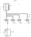
FIG. 1 illustrates air conditioning system, according to an embodiment of the disclosure; -
FIG. 2 is a control block diagram of an electronic device, according to an embodiment of the disclosure; -
FIG. 3 is a diagram for describing an occasion when an electronic device trains a neural network, according to an embodiment of the disclosure; -
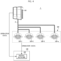
FIG. 4 is a diagram for describing an occasion when an electronic device determines a heat exchanger with degraded performance based on an output from a neural network for operation data, according to an embodiment of the disclosure; -
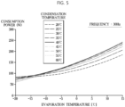
FIG. 5 illustrates compressor map data, according to an embodiment of the disclosure; -
FIG. 6 illustrates an occasion when an electronic device determines a rate of increase in energy depending on the accumulated number of operation days, according to an embodiment of the disclosure; -
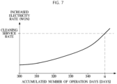
FIG. 7 is a diagram for describing an occasion when an electronic device determines a cleaning period of a heat exchanger, according to an embodiment of the disclosure; -
FIG. 8 illustrates an example in which an electronic device displays information indicating cleaning periods of heat exchangers, according to an embodiment of the disclosure;FIG. 9 illustrates an example in which an electronic device displays information indicating cleaning periods of heat exchangers, according to an embodiment of the disclosure; and -
FIG. 10 is a flowchart of notifying a cleaning period in a method of controlling an electronic device, according to an embodiment of the disclosure. - Embodiments and features as described and illustrated in the disclosure are merely examples, and there may be various modifications replacing the embodiments and drawings at the time of filing this application.
- It will be further understood that the term "connect" or its derivatives refer both to direct and indirect connection, and the indirect connection includes a connection over a wireless communication network.
- The terminology used herein is for the purpose of describing particular embodiments only and is not intended to limit the disclosure. It is to be understood that the singular forms "a," "an," and "the" include plural references unless the context clearly dictates otherwise. It will be further understood that the terms "comprise" and/or "comprising," when used in this specification, specify the presence of stated features, integers, steps, operations, elements, and/or components, but do not preclude the presence or addition of one or more other features, integers, steps, operations, elements, components, and/or groups thereof.
- The terms including ordinal numbers like "first" and "second" may be used to explain various components, but the components are not limited by the terms. The terms are only for the purpose of distinguishing a component from another. Thus, a first element, component, region, layer or room discussed below could be termed a second element, component, region, layer or section without departing from the teachings of the disclosure.
- Furthermore, the terms, such as "~ part", "~ block", "~ member", "~ module", etc., may refer to a unit of handling at least one function or operation. For example, the terms may refer to at least one process handled by hardware such as field-programmable gate array (FPGA)/application specific integrated circuit (ASIC), etc., software stored in a memory, or at least one processor.
- Terminology such as "at least one of A and B", as used herein, includes any of the following: A, B, A and B. Similarly, terminology such as "at least one of A, B, and C", as used herein, includes any of the following: A, B, C, A and B, A and C, B and C, A and Band C.Reference numerals used for method steps are just used to identify the respective steps, but not to limit an order of the steps. Thus, unless the context clearly dictates otherwise, the written order may also be practiced otherwise.
- Reference will now be made in detail to embodiments of the disclosure, which are illustrated in the accompanying drawings.
-
FIG. 1 illustrates air conditioning system, according to an embodiment of the disclosure. - Referring to
FIG. 1 , anair conditioning system 1 may include at least oneoutdoor unit 110, a plurality ofindoor units 120 connected to the at least oneoutdoor unit 110, and anelectronic device 130 that may control theoutdoor unit 110 and the plurality ofindoor units 120. - For example, as shown in
FIG. 1 , theair conditioning system 1 may include the oneoutdoor unit 110 and the plurality of indoor units 120-1, 120-2, 120-3, ..., 120-n: 120 connected to the oneoutdoor unit 110. However, unlike what is shown inFIG. 1 , theair conditioning system 1 may include a plurality of outdoor units, each of which may be connected to the plurality ofindoor units 120. Although the singleoutdoor unit 110 will now be taken as an example, it is not limited thereto and the disclosure will be equally applied to an embodiment in which theoutdoor unit 110 is provided in the plural. - Furthermore, the
air conditioning system 1 may include a refrigerant path P in which a refrigerant is circulated between theoutdoor unit 110 and theindoor unit 120, i.e., the refrigerant may be circulated between theoutdoor unit 110 and theindoor unit 120 along the refrigerant path P. - In an embodiment of the disclosure, the
outdoor unit 110 may include a compressor for compressing the refrigerant, an outdoor heat exchanger for performing heat exchange between outside air and the refrigerant, an outdoor blower fan arranged around the outdoor heat exchanger for blowing the outside air to the outdoor heat exchanger so that the refrigerant and the outside air may exchange heat in the outdoor heat exchanger, a four-way valve for leading the refrigerant compressed by the compressor selectively to one of the outdoor heat exchanger and the indoor unit depending on cooling operation or heating operation, an expansion valve for decompressing the refrigerant, and an accumulator for preventing a refrigerant liquid that has not yet been evaporated from flowing into the compressor. - In an embodiment of the disclosure, the
indoor unit 120 may include an indoor heat exchanger for performing heat exchange between inside air and the refrigerant, and an indoor blower fan for blowing the inside air to the indoor heat exchanger. - The refrigerant may emit heat in the outdoor heat exchanger and absorb heat in the indoor heat exchanger during the cooling operation. Specifically, the refrigerant compressed by the compressor may be supplied first to the outdoor heat exchanger through the four-way valve and then supplied to the indoor heat exchanger during the cooling operation. In this case, the outdoor heat exchanger may function as a condenser that condenses the refrigerant, and the indoor heat exchanger may function as an evaporator that evaporates the refrigerant.
- The refrigerant may emit heat in the indoor heat exchanger and absorb heat in the outdoor heat exchanger during the heating operation. Specifically, the refrigerant compressed by the compressor may be supplied first to the indoor heat exchanger through the four-way valve and then supplied to the outdoor heat exchanger during the heating operation. In this case, the indoor heat exchanger may function as a condenser that condenses the refrigerant, and the outdoor heat exchanger may function as an evaporator that evaporates the refrigerant.
- In an embodiment of the disclosure, the
electronic device 130 may control the at least oneoutdoor unit 110 and the plurality ofindoor units 120 connected to the at least oneoutdoor unit 110. Specifically, theelectronic device 130 may receive operation data from each unit, transmit a control command to the unit, or determine a cleaning period of a heat exchanger of the unit. - For example, the
electronic device 130 may correspond to a control device that is able to control components of theair conditioning system 1, such as a building automation system (BAS) or a building energy management system (BEMS). - Specifically, the
electronic device 130 may determine a heat exchanger with a contamination level equal to or higher than a preset contamination level based on an output from a neural network for the operation data received from each of theoutdoor unit 110 and theindoor unit 120. For example, theelectronic device 130 may use a neural network trained with operation data that varies by contamination level to determine a unit (at least one of theoutdoor unit 110 and the plurality of indoor units 120) having a heat exchanger with a high contamination level. - Furthermore, the
electronic device 130 may determine a cleaning period of the heat exchanger based on a rate of increase in energy in the heat exchanger with the high contamination level, and notify the cleaning period to the user. - In other words, the
electronic device 130 may determine a target unit having a heat exchanger with a high contamination level based on the operation data received from each of the at least oneoutdoor unit 110 and the plurality ofindoor units 120 connected to the at least oneoutdoor unit 110 and determine and notify a cleaning period based on a rate of increase in energy in the heat exchanger of the target unit, thereby resolving difficulties in identifying a target to be cleaned and determining a cleaning period due to the nature of the system air conditioner with a lot of constituent units. - Determining a heat exchanger with a high contamination level and determining a cleaning period of the heat exchanger will be described later in detail.
- Although not shown, the
air conditioning system 1 may also include a distributor (not shown) arranged in the refrigerant path P between theoutdoor unit 110 and theindoor unit 120 for distributing the refrigerant supplied from theoutdoor unit 110 to eachindoor unit 120 according to an operation mode of theindoor unit 120 in an embodiment of the disclosure. - The components included in the
air conditioning system 1 have thus far been described. How theelectronic device 130 determines a unit having a heat exchanger with a high contamination level and notifies a cleaning period of the heat exchanger will now be described in detail. -
FIG. 2 is a control block diagram of theelectronic device 130, according to an embodiment of the disclosure. - Referring to
FIG. 2 , theelectronic device 130 includes auser interface 131 for receiving an input from the user or outputting various information, acommunication module 132 for communicating with theoutdoor unit 110 and theindoor unit 120 included in theair conditioning system 1, acontroller 133 for identifying a heat exchanger with a high contamination level and notifying the cleaning period, and astorage 134 for storing various information required for control. - At least one component may be added to or omitted from the electronic device 160 to correspond to the performance of the
electronic device 130 as shown inFIG. 2 . Furthermore, it will be obvious to those of ordinary skill in the art that the relative positions of the components may be changed to correspond to the system performance or structure. - In an embodiment of the disclosure, the
user interface 131 may receive an input from the user or output various information. For this, theuser interface 131 may include a known-type of input device and a known-type of display panel, or in an embodiment of the disclosure, may include a touch panel in which an input device and a display panel are integrally formed. - In an embodiment of the disclosure, the
communication module 132 may transmit or receive data to or from theoutdoor unit 110 and theindoor unit 120 included in theair conditioning system 1. Specifically, thecommunication module 132 may perform wired or wireless communication with theoutdoor unit 110 and theindoor unit 120. For this, thecommunication module 132 may be provided as a known-type of communication module. - In an embodiment of the disclosure, the
controller 133 may determine a heat exchanger with a contamination level equal to or higher than a preset contamination level among the outdoor heat exchanger of theoutdoor unit 110 and the indoor heat exchanger of theindoor unit 120 based on an output of the neural network for operation data received from each of theoutdoor unit 110 and theindoor unit 120 included in theair conditioning system 1. In the following description, a heat exchanger may correspond to at least one of the outdoor heat exchanger of theoutdoor unit 110 or the indoor heat exchanger of theindoor unit 120. - The preset contamination level may be set according to an input of the user. Contamination of a heat exchanger may mean that contaminants such as dust accumulate on the heat exchanger and a filter of the heat exchanger with use, leading to a reduction in efficiency of heat exchange and air flow rate.
- The operation data may include at least one of pressure of a heat exchanger, temperature of a heat exchanger, a frequency of a compressor, and a number of revolutions of the outdoor blower fan. As an additional example , the operation data may include at least one of pressure and refrigerant condensation temperature in a heat exchanger that functions as a condenser, pressure and refrigerant evaporation temperature in a heat exchanger that functions as an evaporator, a frequency of a compressor, and a number of revolutions of the outdoor blower fan.
- For this, the
outdoor unit 110 may include a pressure sensor and a temperature sensor arranged on one side of the outdoor heat exchanger, a revolution count sensor for detecting the number of revolutions of a motor of the compressor, and a revolution count sensor for detecting the number of revolutions of the outdoor blower fan. Theoutdoor unit 110 may further include at least one processor and a communication module, and the at least one processor may determine operation data based on an output value from a sensor and control the communication module to transmit the operation data to theelectronic device 130. In this case, the processor of theoutdoor unit 110 may determine a frequency of the compressor based on the number of revolutions of the compressor motor. - Furthermore, the
indoor unit 120 may include a pressure sensor and a temperature sensor arranged on one side of the indoor heat exchanger, and include at least one processor and a communication module. The processor of theindoor unit 120 may determine operation data based on an output value from a sensor and control the communication module to transmit the operation data to theelectronic device 130. - The neural network may be trained with the operation data that varies by contamination level of a heat exchanger. The operation data used to train the neural network may also include at least one of pressure of a heat exchanger, temperature of a heat exchanger, a frequency of the compressor, and a number of revolutions of the outdoor blower fan.
- Specifically, the
controller 133 may train the neural network with operation data for each contamination level in a heat exchanger contamination reconstruction experiment as training data. In the heat exchanger contamination reconstruction experiment, a device for suppressing flows of air around the heat exchanger, e.g., a windbreaker, may be installed to reconstruct contamination of the heat exchanger, in which case the measured operation data and a reconstructed contamination level may be used as the training data for the neural network. - The neural network refers to machine learning that embodies a neural structure capable of performing deep learning, and as weight and bias corresponding to elements of the neural network keep changing, learning confidence is improved. In other words, the neural network may keep updating weights, biases, and activation functions included in the neural network based on the operation data that varies by the reconstructed contamination level, thereby enhancing inference results of the neural network.
- The neural network may include a convolution neural network (CNN) that generates a features map output by convolution of the operation data and inputs the features map to the neural network but it is not limited thereto and may be implemented with another deep learning algorithm including a recurrent neural network (RNN). That is, there is no limitations on the type of the neural network.
- In an embodiment of the disclosure, the
controller 133 may determine a cleaning period of the heat exchanger determined to have a contamination level equal to or higher than the preset contamination level based on a rate of increase in energy of the heat exchanger, and control theuser interface 131 to output the cleaning period. - Specifically, the
controller 133 may determine a rate of increase in energy of the heat exchanger determined to have a contamination level equal to or higher than the preset contamination level to be a ratio between power measured by a watt-hour meter and reference power calculated based on the compressor map data. - The watt-hour meter may be provided for each of the
outdoor unit 110 and theindoor unit 120 for detecting power consumed by the corresponding unit. For this, the watt-hour meter may be provided as a known-type of watt-hour meter. - The compressor map data may be experimental result data on power consumption of the compressor depending on a change in saturated evaporation temperature of a heat exchanger, saturated condensation temperature of the heat exchanger and frequency of the compressor in a design environment.
- In an embodiment of the disclosure, the
controller 133 may determine the reference power depending on evaporation temperature of a heat exchanger, condensation temperature of the heat exchanger and a frequency of the compressor based on the compressor map data, Specifically, thecontroller 133 may determine the reference power depending on a refrigerant saturated evaporation temperature in a heat exchanger that functions as an evaporator, a refrigerant saturated condensation temperature in a heat exchanger that functions as a condenser, and a compressor frequency through regression analysis using the compressor map data in a design stage. Specifically, thecontroller 133 may build up a virtual sensor that expects consumption power, i.e., reference power, based on a saturated evaporation temperature and a saturated condensation temperature of a heat exchanger and a compressor frequency by using the compressor map data determined in a design environment, and calculate reference power by inputting the saturated evaporation temperature and the saturated condensation temperature of the heat exchanger and compressor frequency data of theair conditioning system 1 being used in an actual building to the virtual sensor. - In an embodiment of the disclosure, the
controller 133 may determine a rate of increase in energy depending on the accumulated number of operation days through regression analysis on the rate of increase in energy determined to be the ratio between the power measured by the watt-hour meter and the reference power calculated based on the compressor map data. - In other words, the
controller 133 may determine a rate of increase in energy having a particular value during a preset period, and determine a rate of increase in energy over time through regression analysis on rates of increase in energy determined in the preset period. - In an embodiment of the disclosure, the
controller 133 may determine an increased electricity rate depending on the accumulated number of operation days based on a rate of increase in energy depending on the accumulated number of operation days and an electricity rate per day. - In other words, the
controller 133 may determine an increased electricity rate per day by multiplying the rate of increase in energy per day and the electricity rate per day, and determine an increased electricity rate depending on the accumulated number of operation days by adding the increased electricity rate per day. - In an embodiment of the disclosure, the
controller 133 may determine a cleaning period by comparing the increased electricity rate depending on the accumulated number of operation days with a preset cleaning service rate. - Specifically, the
controller 133 may determine a difference between a date at which the increased electricity rate depending on the accumulated number of operation days exceeds the preset cleaning service rate and a previous cleaning date as the cleaning period. - As described above, the
controller 133 may control theuser interface 131 to output the determined cleaning period, and in an embodiment of the disclosure, may control thecommunication module 132 to transmit the cleaning period to a user interface of a user terminal or theindoor unit 120. - The
controller 133 may include at least one memory for storing a program for carrying out the aforementioned and following operations, and at least one processor for executing the program. - The
storage 134 may store various information required for control. For example, thestorage 134 may store e.g., the neural network trained with the operation data that varies by contamination level of a heat exchanger. For this, thestorage 134 may be provided as a known-type of storage medium. -
FIG. 3 is a diagram for describing an occasion when theelectronic device 130 trains a neural network, according to an embodiment of the disclosure. - Referring to
FIG. 3 , theelectronic device 130 may train aneural network 135 with operation data for each contamination level in the heat exchanger contamination reconstruction experiment as training data. - In the heat exchanger contamination reconstruction experiment, a device for suppressing flows of air around the heat exchanger, e.g., a windbreaker, may be installed to reconstruct contamination of the heat exchanger, in which case the measured operation data and a reconstructed contamination level may be used as the training data for the
neural network 135. - In other words, in the heat exchanger contamination reconstruction experiment, a device for suppressing flows of air around at least one heat exchanger of the
outdoor unit 110 or theindoor unit 120 may be installed, and theelectronic device 130 may obtain operation data for each degree of suppressing flows of air from theoutdoor unit 110 and theindoor unit 120 and use the operation data as the operation data that varies by contamination level. - With this, the
neural network 135 may be trained with the operation data that varies by contamination level of a heat exchanger. The operation data used to train theneural network 135 may also include at least one of pressure of a heat exchanger, temperature of the heat exchanger, a frequency of a compressor, and a number of revolutions of the outdoor blower fan. As an additional example, the operation data may include at least one of pressure and refrigerant condensation temperature in a heat exchanger that functions as a condenser, pressure and refrigerant evaporation temperature in a heat exchanger that functions as an evaporator, a frequency of the compressor, and a number of revolutions of the outdoor blower fan. - The
neural network 135 refers to machine learning that embodies a neural structure capable of performing deep learning, and as weight and bias corresponding to elements of theneural network 135 keep changing, learning confidence is improved. In other words, theneural network 135 may keep updating weights, biases, and activation functions included in theneural network 135 based on the operation data that varies by the reconstructed contamination level, thereby enhancing inference results of theneural network 135. - The training may be, for example, supervised learning having operation data as an input and a contamination data as an output.
- The
neural network 135 may include a CNN that generates a features map output by convolution of the operation data and inputs the features map to the neural network but it is not limited thereto and may be implemented with another deep learning algorithm including an RNN. That is, there is no limitation on the type of theneural network 135. -
FIG. 4 is a diagram for describing an occasion when theelectronic device 130 determines a heat exchanger with degraded performance based on an output from theneural network 135 for operation data, according to an embodiment of the disclosure. - In general, when the heat exchanger collects dust and has a higher contamination level, the air flow rate is reduced, causing a reduction in cooling or heating efficiency and an increase in electricity rate. Hence, periodic cleaning of the heat exchanger is required, but the system air conditioner may have difficulty in determining which device (or unit) is to be cleaned because the system air conditioner has a lot of devices (units).
- In the disclosure, the
electronic device 130 may identify a device with degraded performance through theneural network 135 and notify a cleaning period of the device to the user. - Referring to
FIG. 4 , theelectronic device 130 may determine a heat exchanger with a contamination level equal to or higher than a preset contamination level among the outdoor heat exchanger of theoutdoor unit 110 and the indoor heat exchanger of theindoor unit 120 based on an output of theneural network 135 for operation data received from each of theoutdoor unit 110 and theindoor unit 120 included in theair conditioning system 1. - In other words, the
electronic device 130 may determine a cleaning period of a target device (unit) by determining a device having a heat exchanger with a contamination level equal to or higher than a preset contamination level as a device with degraded performance. For example, as shown inFIG. 4 , theelectronic device 130 may determine the contamination level of the outdoor heat exchanger equal to or higher than the preset contamination level as performance degradation of theoutdoor unit 110, and determine a cleaning period of the outdoor heat exchanger in theoutdoor unit 110 - The preset contamination level may be set according to an input of the user. Contamination of a heat exchanger may mean that contaminants such as dust accumulate on the heat exchanger and a filter of the heat exchanger with use, leading to a reduction in efficiency of heat exchange and air flow rate.
- The operation data may include at least one of pressure of the heat exchanger, temperature of the heat exchanger, a frequency of the compressor, and a number of revolutions of the outdoor blower fan. Specifically, the operation data may include at least one of pressure and refrigerant condensation temperature in a heat exchanger that functions as a condenser, pressure and refrigerant evaporation temperature in a heat exchanger that functions as an evaporator, a frequency of a compressor, and a number of revolutions of the outdoor blower fan.
-
FIG, 5 illustrates compressor map data, according to an embodiment of the disclosure,FIG, 6 illustrates an occasion when theelectronic device 130 determines a rate of increase in energy depending on the accumulated number of operation days, according to an embodiment of the disclosure,FIG, 7 is a diagram for describing an occasion when theelectronic device 130 determines a cleaning period of a heat exchanger, according to an embodiment of the disclosure,FIG. 8 illustrates an example in which theelectronic device 130 displays information indicating cleaning periods of heat exchangers, according to an embodiment of the disclosure, andFIG. 9 illustrates an example in which theelectronic device 130 displays information indicating cleaning periods of heat exchangers, according to an embodiment of the disclosure. - Referring to
FIGS. 5 to 9 , theelectronic device 130 may determine a cleaning period of a heat exchanger determined to have a contamination level equal to or higher than the preset contamination level based on a rate of increase in energy of the heat exchange, and control theuser interface 131 to output the cleaning period. - Specifically, the
electronic device 130 may determine a rate of increase in energy Kp of the heat exchanger determined to have a contamination level equal to or higher than the preset contamination level to be a ratio between power Pmeasured measured by a watt-hour meter and reference power Prated calculated based on the compressor map data, as expressed in the following equation 1:
<equation 1>

- The watt-hour meter may be provided for each of the
outdoor unit 110 and theindoor unit 120 for detecting power consumed by the corresponding unit. For this, the watt-hour meter may be provided as a known-type of watt-hour meter. - As shown in
FIG. 5 , the compressor map data may be experimental result data on power consumption of a compressor depending on a change in saturated evaporation temperature of a heat exchanger, saturated condensation temperature of the heat exchanger and frequency of the compressor in a design environment. The compressor map data may include data resulting from a simulation corresponding to each frequency of the compressor. - For example, the compressor map data may be obtained by using software (e.g., software in the loop simulation (SIILS)) that performs a simulation with a virtual sensor in a design stage.
- The software that performs the simulation may implement the virtual sensor by reconstructing memory operations or interrupt operations of an actual sensor in a personal computer (PC) and use the virtual sensor to measure the compressor power consumption depending on a change in the saturated evaporation temperature of a heat exchanger, the saturated condensation temperature of a heat exchanger and frequency of the compressor.
- In an embodiment of the disclosure, the
controller 133 may determine the reference power Prated depending on evaporation temperature of a heat exchanger, condensation temperature of the heat exchanger and a frequency of the compressor based on the compressor map data. - Specifically, the
controller 133 may determine the reference power Prated depending on a refrigerant saturated evaporation temperature in a heat exchanger that functions as an evaporator and a refrigerant saturated condensation temperature in a heat exchanger that functions as a condenser through regression analysis using the compressor map data determined in a design stage. - For example, the reference power Prated may be determined by a regression analysis equation based on a condensation temperature Tc and an evaporation temperature Te as expressed in the following equation 2:
<equation 2>

- Specifically, the
controller 133 may build up a virtual sensor that expects consumption power, i.e., reference power Prated, based on a saturated evaporation temperature and a saturated condensation temperature of a heat exchanger and a compressor frequency by using the compressor map data determined in a design environment, and calculate the reference power Prated by inputting the saturated evaporation temperature and the saturated condensation temperature of the heat exchanger and compressor frequency data of theair conditioning system 1 being used in an actual building to the virtual sensor. - In an embodiment of the disclosure, through regression analysis on the rate of increase in energy Kpdetermined to be a ratio between the power Pmeasured measured by a watt-hour meter and the reference power Prated calculated based on the compressor map data, the
electronic device 130 may determine a rate of increase in energy Kp depending on the accumulated number of operation days tc as in the following equation 3 and shown inFIG. 6 .
<equation 3>

- In other words, the
electronic device 130 may determine a rate of increase in energy Kp having a particular value during a preset period, and determine a rate of increase in energy Kp over time tc through regression analysis on rates of increase in energy Kp determined in the preset period. - In an embodiment of the disclosure, the
electronic device 130 may determine an increased electricity rate depending on the accumulated number of operation days tc based on a rate of increase in energy Kp depending on the accumulated number of operation days tc and an electricity rate per day. - In other words, the
electronic device 130 may determine an increased electricity rate per day by multiplying the rate of increase in energy Kp per day and the electricity rate per day, and determine an increased electricity rate depending on the accumulated number of operation days tc by adding the increased electricity rate per day. - In this case, the
electronic device 130 may calculate an electricity rate per day based on the past rate data, and separately calculate the electricity rate per day in the cooling mode and the electricity rate per day in the heating mode. - In an embodiment of the disclosure, the electronic 130 may determine a cleaning period by comparing the increased electricity rate depending on the accumulated number of operation days tc with a preset cleaning service rate, as shown in
FIG. 7 . - Specifically, the
electronic device 130 may determine a difference between a date at which the increased electricity rate depending on the accumulated number of operation days tc exceeds the preset cleaning service rate and a previous cleaning date as the cleaning period. - In an embodiment of the disclosure, the
electronic device 130 may control theuser interface 131 to output the determined cleaning period. - For example, the
electronic device 130 may display information indicating a cleaning period for each of at least one unit (an outdoor unit, a first indoor unit, and a second indoor unit detected to have degraded performance among the units included in theair conditioning system 1, and notify that the unit determined to be in need of cleaning according to the cleaning period needs to be cleaned. - Furthermore, the
electronic device 130 may display information indicating a cleaning period for each of at least one outdoor unit (a first outdoor unit, a second outdoor unit, and a third outdoor unit) detected to have degraded performance among the plurality of outdoor units included in theair conditioning system 1, and notify that the unit determined to be in need of cleaning according to the cleaning period needs to be cleaned. - An embodiment of a method of controlling the
electronic device 130 will now be described from a perspective. As for the method of controlling theelectronic device 130, theelectronic device 130 in the aforementioned embodiments may be used. Hence, what are described above with reference toFIGS. 1 to 9 may be equally applied in the following method of controlling theelectronic device 130. -
FIG. 10 is a flowchart of notifying a cleaning period in a method of controlling theelectronic device 130, according to an embodiment of the disclosure. - Referring to
FIG. 10 , theelectronic device 130 may receive operation data from each of theindoor unit 120 and theoutdoor unit 110, in 1010. - That is, the
electronic device 130 may receive operation data from each of theoutdoor unit 110 and theindoor unit 120 included in theair conditioning system 1 through thecommunication module 132. - Specifically, the
electronic device 130 may receive operation data from each of the at least oneoutdoor unit 100 and the plurality ofindoor units 120 connected to the at least oneoutdoor unit 110. - The
electronic device 130 may obtain an output of theneural network 135 for the operation data as input data. - In this case, the operation data may include at least one of pressure of a heat exchanger, temperature of the heat exchanger, a frequency of a compressor, and a number of revolutions of the outdoor blower fan. Specifically, the operation data may include at least one of pressure and refrigerant condensation temperature in a heat exchanger that functions as a condenser, pressure and refrigerant evaporation temperature in a heat exchanger that functions as an evaporator, a frequency of the compressor, and a number of revolutions of the outdoor blower fan.
- Furthermore, the
neural network 135 may be trained with the operation data that varies by contamination level of a heat exchanger. Specifically, theelectronic device 130 may train the neural network with operation data for each contamination level in a heat exchanger contamination reconstruction experiment as training data. In the heat exchanger contamination reconstruction experiment, a device for suppressing flows of air around the heat exchanger, e.g., a windbreaker, may be installed to reconstruct contamination of the heat exchanger, in which case the measured operation data and a reconstructed contamination level may be used as the training data for theneural network 135. - In an embodiment of the disclosure, the
electronic device 130 may determine a heat exchanger with a contamination level equal to or higher than a preset contamination level based on the output of theneural network 135, in 1030. - specifically, the
electronic device 130 may determine a heat exchanger with a contamination level equal to or higher than a preset contamination level among the outdoor heat exchanger of theoutdoor unit 110 and the indoor heat exchanger of theindoor unit 120 based on an output of theneural network 135 for the operation data received from each of theoutdoor unit 110 and theindoor unit 120 included in theair conditioning system 1. - The preset contamination level may be set according to an input of the user. Contamination of a heat exchanger may mean that contaminants such as dust accumulate on the heat exchanger and a filter of the heat exchanger with use, leading to a reduction in efficiency of heat exchange and air flow rate.
- In an embodiment of the disclosure, as for the heat exchanger determined to have a contamination level equal to or higher than the preset contamination level, the
electronic device 130 may determine a rate of increase in energy Kp of the heat exchanger determined to have a contamination level equal to or higher than the preset contamination level to be a ratio between power Pmeasured measured by a watt-hour meter and reference power Prated calculated based on the compressor map data, in 1040. - Furthermore, the
electronic device 130 may determine a rate of increase in energy Kp depending on the accumulated number of operation days tc through regression analysis on the determined rate of increase in energy Kp, in 1050. - In other words, the
electronic device 130 may determine a rate of increase in energy Kp having a particular value during a preset period, and determine a rate of increase in energy Kp over time tc through regression analysis on rates of increase in energy Kp determined in the preset period. - In an embodiment of the disclosure, the
electronic device 130 may determine an increased electricity rate depending on the accumulated number of operation days tc based on a rate of increase in energy Kp depending on the accumulated number of operation days tc and an electricity rate per day, in 1060. - In other words, the
electronic device 130 may determine an increased electricity rate per day by multiplying the rate of increase in energy Kp per day and the electricity rate per day, and determine an increased electricity rate depending on the accumulated number of operation days tc by adding the increased electricity rate per day. - In this case, the
electronic device 130 may calculate an electricity rate per day based on the past rate data, and separately calculate the electricity rate per day in the cooling mode and the electricity rate per day in the heating mode. - The
electronic device 130 may determine a cleaning period by comparing the increased electricity rate depending on the accumulated number of operation days tc with a preset cleaning service rate in 1070, and output the determined cleaning period in 180. - Specifically, the
electronic device 130 may determine a difference between a date at which the increased electricity rate depending on the accumulated number of operation days tc exceeds the preset cleaning service rate and a previous cleaning date as the cleaning period. - Meanwhile, the embodiments of the disclosure may be implemented in the form of a recording medium for storing instructions to be carried out by a computer. The instructions may be stored in the form of program codes, and when executed by a processor, may generate program modules to perform operation in the embodiments of the disclosure. The recording media may correspond to computer-readable recording media.
- The computer-readable recording medium includes any type of recording medium having data stored thereon that may be thereafter read by a computer. For example, it may be a read only memory (ROM), a random access memory (RAM), a magnetic tape, a magnetic disk, a flash memory, an optical data storage device, etc.
- The embodiments of the disclosure have thus far been described with reference to accompanying drawings. It will be obvious to those of ordinary skill in the art that the disclosure may be practiced in other forms than the embodiments as described above without changing the technical idea or essential features of the disclosure. The above embodiments of the disclosure are only by way of example, and should not be construed in a limited sense.
Claims (15)
- An electronic device comprising:a user interface;a communication module configured to perform communication with at least one outdoor unit and a plurality of indoor units connected to the at least one outdoor unit; anda processor configured to determine a heat exchanger with a contamination level equal to or higher than a preset contamination level among a heat exchanger of the at least one outdoor unit and heat exchangers of the plurality of indoor units based on an output from a neural network for operation data received from each of the at least one outdoor unit and the plurality of indoor units, determine a cleaning period of the determined heat exchanger based on a rate of increase in energy of the determined heat exchanger, and control the user interface to output information indicating the determined cleaning period.
- The electronic device of claim 1, whereinthe neural network is trained with operation data varying by contamination level of a heat exchanger, andeach of the operation data received from each of the at least one outdoor unit and the plurality of indoor units and the operation data varying by contamination level of the heat exchanger comprises at least one of pressure of a heat exchanger, temperature of a heat exchanger, a frequency of a compressor of the outdoor unit, and a number of revolutions of a blower fan of the at least one outdoor unit.
- The electronic device of claim 1, wherein the at least one processor is configured to determine the rate of increase in energy to be a ratio between power measured through a watt-hour meter and reference power calculated based on compressor map data.
- The electronic device of claim 3, wherein the compressor map data is experimental result data on power consumption of a compressor depending on a change in saturated evaporation temperature of a heat exchanger, saturated condensation temperature of a heat exchanger and compressor frequency in a design environment.
- The electronic device of claim 4, wherein the at least one processor is configured to determine the reference power depending on the saturated evaporation temperature of the heat exchanger, the saturated condensation temperature of the heat exchanger and the compressor frequency based on the compressor map data.
- The electronic device of claim 3, wherein the at least one processor is configured to determine a rate of increase in energy depending on an accumulated number of operation days through regression analysis on the rate of increase in energy.
- The electronic device of claim 6, wherein the at least one processor is configured to determine an increased electricity rate depending on the accumulated number of operation days based on the rate of increase in energy depending on the accumulated number of operation days and an electricity rate per day.
- The electronic device of claim 7, wherein the at least one processor is configured to determine the cleaning period by comparing the increased electricity rate depending on the accumulated number of operation days with a preset cleaning service rate.
- The electronic device of claim 8, wherein the at least one processor is configured to determine a difference between a date at which the increased electricity rate depending on the accumulated number of operation days exceeds the preset cleaning service rate and a previous cleaning date as the cleaning period.
- The electronic device of claim 1, further comprising the neural network, wherein the neural network is trained with operation data varying by contamination level of a heat exchanger.
- A method of controlling an electronic device including a user interface and that communicates with at least one outdoor unit and a plurality of indoor units connected to the at least one outdoor unit, the method comprising:determining a heat exchanger with a contamination level equal to or higher than a preset contamination level among a heat exchanger of the at least one outdoor unit and heat exchangers of the plurality of indoor units based on an output from a neural network for operation data received from each of the at least one outdoor unit and the plurality of indoor units;determining a cleaning period of the determined heat exchanger based on a rate of increase in energy of the determined heat exchanger; andcontrolling the user interface to output information indicating the determined cleaning period.
- The method of claim 11, whereinthe neural network is trained with operation data varying by contamination level of a heat exchanger, andeach of the operation data received from each of the at least one outdoor unit and the plurality of indoor units and the operation data varying by contamination level of the heat exchanger comprises at least one of pressure of a heat exchanger, temperature of a heat exchanger, a frequency of a compressor of the outdoor unit, and a number of revolutions of a blower fan of the at least one outdoor unit.
- The method of claim 11, wherein the determining of the cleaning period comprises determining the rate of increase in energy to be a ratio between power measured through a watt-hour meter and reference power calculated based on compressor map data.
- The method of claim 13, wherein the compressor map data is experimental result data on power consumption of a compressor depending on a change in saturated evaporation temperature of a heat exchanger, saturated condensation temperature of a heat exchanger and compressor frequency in a design environment.
- The method of claim 11, further comprising:
training the neural network with operation data varying by contamination level of a heat exchanger.
Priority Applications (1)
| Application Number | Priority Date | Filing Date | Title |
|---|---|---|---|
| EP25199625.2A EP4636333A3 (en) | 2022-02-28 | 2022-12-15 | Air conditioning system, electronic device, and control method thereof |
Applications Claiming Priority (2)
| Application Number | Priority Date | Filing Date | Title |
|---|---|---|---|
| KR1020220026329A KR20230128867A (en) | 2022-02-28 | 2022-02-28 | Air conditioning system, electronic device, and cotnrol method of the same |
| PCT/KR2022/020412 WO2023163344A1 (en) | 2022-02-28 | 2022-12-15 | Air conditioning system, electronic device, and control method thereof |
Related Child Applications (2)
| Application Number | Title | Priority Date | Filing Date |
|---|---|---|---|
| EP25199625.2A Division EP4636333A3 (en) | 2022-02-28 | 2022-12-15 | Air conditioning system, electronic device, and control method thereof |
| EP25199625.2A Division-Into EP4636333A3 (en) | 2022-02-28 | 2022-12-15 | Air conditioning system, electronic device, and control method thereof |
Publications (4)
| Publication Number | Publication Date |
|---|---|
| EP4390259A1 true EP4390259A1 (en) | 2024-06-26 |
| EP4390259A4 EP4390259A4 (en) | 2025-01-15 |
| EP4390259C0 EP4390259C0 (en) | 2025-10-29 |
| EP4390259B1 EP4390259B1 (en) | 2025-10-29 |
Family
ID=87761507
Family Applications (2)
| Application Number | Title | Priority Date | Filing Date |
|---|---|---|---|
| EP25199625.2A Pending EP4636333A3 (en) | 2022-02-28 | 2022-12-15 | Air conditioning system, electronic device, and control method thereof |
| EP22929092.9A Active EP4390259B1 (en) | 2022-02-28 | 2022-12-15 | Air conditioning system, electronic device, and control method thereof |
Family Applications Before (1)
| Application Number | Title | Priority Date | Filing Date |
|---|---|---|---|
| EP25199625.2A Pending EP4636333A3 (en) | 2022-02-28 | 2022-12-15 | Air conditioning system, electronic device, and control method thereof |
Country Status (3)
| Country | Link |
|---|---|
| US (1) | US12523388B2 (en) |
| EP (2) | EP4636333A3 (en) |
| CN (1) | CN118076841A (en) |
Family Cites Families (26)
| Publication number | Priority date | Publication date | Assignee | Title |
|---|---|---|---|---|
| US5860285A (en) | 1997-06-06 | 1999-01-19 | Carrier Corporation | System for monitoring outdoor heat exchanger coil |
| US7147168B1 (en) * | 2003-08-11 | 2006-12-12 | Halton Company | Zone control of space conditioning system with varied uses |
| KR20040033357A (en) | 2002-10-14 | 2004-04-28 | 삼성전자주식회사 | Air conditioner |
| KR20040044684A (en) * | 2002-11-21 | 2004-05-31 | 엘지전자 주식회사 | Decontamination apparatus of an air-conditioner's heat exchanger |
| US20050269254A1 (en) * | 2004-05-24 | 2005-12-08 | Roitman Lipa L | [Air and Water Purifying System And Filter Media] |
| JP4775338B2 (en) | 2007-07-12 | 2011-09-21 | ダイキン工業株式会社 | Air conditioner deterioration determination device, air conditioning system, deterioration determination method, and deterioration determination program |
| WO2010151876A2 (en) | 2009-06-26 | 2010-12-29 | Greenair Process, Llc | Method for cleaning hvac system and method and system for verifying cleaning effectiveness |
| CN104272034B (en) * | 2012-02-28 | 2017-05-24 | 艾默生电气公司 | HVAC system remote monitoring and diagnosis |
| KR20150000691U (en) | 2013-08-07 | 2015-02-17 | 양민우 | Air conditioning outdoor unit clean notification device |
| KR101592998B1 (en) | 2014-05-08 | 2016-02-18 | 엘지전자 주식회사 | Air-conditioner System and Method |
| WO2015175821A1 (en) * | 2014-05-15 | 2015-11-19 | Emerson Electric Co. | Hvac system air filter diagnostics and monitoring |
| US10496065B2 (en) * | 2016-04-11 | 2019-12-03 | Emerson Electric Co. | Systems and methods for mobile application for HVAC installation and diagnostics |
| JP6731865B2 (en) | 2017-02-06 | 2020-07-29 | 日立ジョンソンコントロールズ空調株式会社 | Air conditioner outdoor unit, air conditioner, and air conditioning management method |
| US11137161B2 (en) * | 2017-03-30 | 2021-10-05 | Samsung Electronics Co., Ltd. | Data learning server and method for generating and using learning model thereof |
| US12242259B2 (en) * | 2017-05-25 | 2025-03-04 | Tyco Fire & Security Gmbh | Model predictive maintenance system with event or condition based performance |
| KR102472214B1 (en) * | 2018-02-28 | 2022-11-30 | 삼성전자주식회사 | Compound control apparatus and method thereof in air conditioning system |
| KR101995311B1 (en) | 2018-05-29 | 2019-09-24 | 경상대학교산학협력단 | Diagnosis method for air conditioning system and device thereof |
| WO2020003528A1 (en) | 2018-06-29 | 2020-01-02 | 日立ジョンソンコントロールズ空調株式会社 | Air conditioning management system, air conditioning management method, and program |
| WO2020069593A1 (en) | 2018-10-05 | 2020-04-09 | S. A. Armstrong Limited | Automatic maintenance and flow control of heat exchanger |
| JP6914297B2 (en) | 2019-07-01 | 2021-08-04 | 日立ジョンソンコントロールズ空調株式会社 | Air conditioner and control method |
| US11480517B2 (en) | 2019-08-08 | 2022-10-25 | Saudi Arabian Oil Company | Heat exchanger fouling determination using thermography combined with machine learning methods |
| KR102296329B1 (en) | 2020-01-13 | 2021-09-01 | 주식회사 유러스 | Smart Air Conditioning System for Optimized Operation with Predictive Co-operation |
| JP7519808B2 (en) | 2020-05-08 | 2024-07-22 | 三菱電機株式会社 | Air conditioner management system, management device, air conditioner, air conditioner management method and program |
| CN111912080A (en) * | 2020-05-26 | 2020-11-10 | 海信(山东)空调有限公司 | Air conditioner and self-cleaning method |
| CN112052564B (en) | 2020-08-10 | 2022-10-11 | 浙江大学 | Heat exchanger predictive maintenance method and system based on machine learning |
| CN113405217A (en) | 2021-06-11 | 2021-09-17 | 珠海格力电器股份有限公司 | Cleaning method and device for filth blockage of air conditioner heat exchanger and air conditioner |
-
2022
- 2022-12-15 EP EP25199625.2A patent/EP4636333A3/en active Pending
- 2022-12-15 EP EP22929092.9A patent/EP4390259B1/en active Active
- 2022-12-15 CN CN202280067408.3A patent/CN118076841A/en active Pending
- 2022-12-27 US US18/089,244 patent/US12523388B2/en active Active
Also Published As
| Publication number | Publication date |
|---|---|
| EP4636333A2 (en) | 2025-10-22 |
| US20230272936A1 (en) | 2023-08-31 |
| EP4636333A3 (en) | 2026-01-07 |
| EP4390259C0 (en) | 2025-10-29 |
| CN118076841A (en) | 2024-05-24 |
| EP4390259A4 (en) | 2025-01-15 |
| EP4390259B1 (en) | 2025-10-29 |
| US12523388B2 (en) | 2026-01-13 |
Similar Documents
| Publication | Publication Date | Title |
|---|---|---|
| JP4980407B2 (en) | Air conditioner control device, refrigeration device control device | |
| US8670871B2 (en) | Load processing balance setting apparatus | |
| JP5404556B2 (en) | Air conditioner control device and refrigeration device control device | |
| JP2993563B2 (en) | System for monitoring outdoor heat exchanger coils | |
| JP7328498B2 (en) | Information processing device, air conditioner, information processing method, air conditioning method, and program | |
| CN113677941A (en) | Performance Deterioration Diagnosis System of Refrigeration Cycle Plant | |
| EP0883047A1 (en) | System for monitoring expansion valve | |
| EP2863139B1 (en) | Air conditioning system | |
| Yang et al. | The impact of evaporator fouling and filtration on the performance of packaged air conditioners | |
| US20140257575A1 (en) | Systems and methods for implementing environmental condition control, monitoring and adjustment in enclosed spaces | |
| Shen et al. | Model-based optimizations of packaged rooftop air conditioners using low global warming potential refrigerants | |
| Xu et al. | Inherent correlation between the total output cooling capacity and equipment sensible heat ratio of a direct expansion air conditioning system under variable-speed operation (XXG SMD SHR DX AC unit) | |
| CN105518394A (en) | Operation control device and operation control method | |
| US12326284B2 (en) | Systems and methods for humidity control in an air conditioning system | |
| EP4390259B1 (en) | Air conditioning system, electronic device, and control method thereof | |
| Li et al. | An overall performance index for characterizing the economic impact of faults in direct expansion cooling equipment | |
| EP4177532B1 (en) | Air conditioner and operation method thereof | |
| Cai | Gray-box modeling of multistage direct-expansion units to enable control system optimization | |
| WO2024135664A1 (en) | Apparatus performance prediction method, apparatus performance prediction device, and program | |
| KR20230128867A (en) | Air conditioning system, electronic device, and cotnrol method of the same | |
| JPWO2023228277A5 (en) | ||
| JP2007093152A (en) | Air conditioner system | |
| Woradechjumroen et al. | Energy interaction among HVAC and supermarket environment | |
| WO2024058149A1 (en) | Apparatus-performance-value prediction method, system, and program | |
| JP2023137957A (en) | Air-conditioner, control device, control method and program |
Legal Events
| Date | Code | Title | Description |
|---|---|---|---|
| STAA | Information on the status of an ep patent application or granted ep patent |
Free format text: STATUS: THE INTERNATIONAL PUBLICATION HAS BEEN MADE |
|
| PUAI | Public reference made under article 153(3) epc to a published international application that has entered the european phase |
Free format text: ORIGINAL CODE: 0009012 |
|
| STAA | Information on the status of an ep patent application or granted ep patent |
Free format text: STATUS: REQUEST FOR EXAMINATION WAS MADE |
|
| 17P | Request for examination filed |
Effective date: 20240319 |
|
| AK | Designated contracting states |
Kind code of ref document: A1 Designated state(s): AL AT BE BG CH CY CZ DE DK EE ES FI FR GB GR HR HU IE IS IT LI LT LU LV MC ME MK MT NL NO PL PT RO RS SE SI SK SM TR |
|
| A4 | Supplementary search report drawn up and despatched |
Effective date: 20241212 |
|
| RIC1 | Information provided on ipc code assigned before grant |
Ipc: F24F 11/32 20180101ALI20241206BHEP Ipc: F24F 140/50 20180101ALI20241206BHEP Ipc: F24F 140/20 20180101ALI20241206BHEP Ipc: F24F 140/12 20180101ALI20241206BHEP Ipc: G06N 3/02 20060101ALI20241206BHEP Ipc: F24F 11/52 20180101ALI20241206BHEP Ipc: F24F 11/64 20180101ALI20241206BHEP Ipc: F24F 11/46 20180101ALI20241206BHEP Ipc: F24F 11/49 20180101AFI20241206BHEP |
|
| REG | Reference to a national code |
Ref country code: DE Ref legal event code: R079 Free format text: PREVIOUS MAIN CLASS: F24F0011490000 Ipc: F24F0140600000 Ref country code: DE Ref legal event code: R079 Ref document number: 602022024220 Country of ref document: DE Free format text: PREVIOUS MAIN CLASS: F24F0011490000 Ipc: F24F0140600000 |
|
| GRAP | Despatch of communication of intention to grant a patent |
Free format text: ORIGINAL CODE: EPIDOSNIGR1 |
|
| STAA | Information on the status of an ep patent application or granted ep patent |
Free format text: STATUS: GRANT OF PATENT IS INTENDED |
|
| DAV | Request for validation of the european patent (deleted) | ||
| DAX | Request for extension of the european patent (deleted) | ||
| RIC1 | Information provided on ipc code assigned before grant |
Ipc: F24F 140/12 20180101ALI20250512BHEP Ipc: F24F 11/32 20180101ALI20250512BHEP Ipc: G06N 3/02 20060101ALI20250512BHEP Ipc: F24F 140/50 20180101ALI20250512BHEP Ipc: F24F 140/20 20180101ALI20250512BHEP Ipc: F24F 11/52 20180101ALI20250512BHEP Ipc: F24F 11/64 20180101ALI20250512BHEP Ipc: F24F 11/46 20180101ALI20250512BHEP Ipc: F24F 11/49 20180101ALI20250512BHEP Ipc: F24F 140/60 20180101AFI20250512BHEP |
|
| INTG | Intention to grant announced |
Effective date: 20250602 |
|
| GRAS | Grant fee paid |
Free format text: ORIGINAL CODE: EPIDOSNIGR3 |
|
| GRAA | (expected) grant |
Free format text: ORIGINAL CODE: 0009210 |
|
| STAA | Information on the status of an ep patent application or granted ep patent |
Free format text: STATUS: THE PATENT HAS BEEN GRANTED |
|
| AK | Designated contracting states |
Kind code of ref document: B1 Designated state(s): AL AT BE BG CH CY CZ DE DK EE ES FI FR GB GR HR HU IE IS IT LI LT LU LV MC ME MK MT NL NO PL PT RO RS SE SI SK SM TR |
|
| REG | Reference to a national code |
Ref country code: CH Ref legal event code: F10 Free format text: ST27 STATUS EVENT CODE: U-0-0-F10-F00 (AS PROVIDED BY THE NATIONAL OFFICE) Effective date: 20251029 Ref country code: GB Ref legal event code: FG4D |
|
| REG | Reference to a national code |
Ref country code: DE Ref legal event code: R096 Ref document number: 602022024220 Country of ref document: DE |
|
| REG | Reference to a national code |
Ref country code: IE Ref legal event code: FG4D |
|
| U01 | Request for unitary effect filed |
Effective date: 20251119 |
|
| U07 | Unitary effect registered |
Designated state(s): AT BE BG DE DK EE FI FR IT LT LU LV MT NL PT RO SE SI Effective date: 20251126 |
|
| PGFP | Annual fee paid to national office [announced via postgrant information from national office to epo] |
Ref country code: AT Payment date: 20260113 Year of fee payment: 4 |
|
| U20 | Renewal fee for the european patent with unitary effect paid |
Year of fee payment: 4 Effective date: 20251223 |
|
| PG25 | Lapsed in a contracting state [announced via postgrant information from national office to epo] |
Ref country code: ES Free format text: LAPSE BECAUSE OF FAILURE TO SUBMIT A TRANSLATION OF THE DESCRIPTION OR TO PAY THE FEE WITHIN THE PRESCRIBED TIME-LIMIT Effective date: 20251029 |
|
| PG25 | Lapsed in a contracting state [announced via postgrant information from national office to epo] |
Ref country code: NO Free format text: LAPSE BECAUSE OF FAILURE TO SUBMIT A TRANSLATION OF THE DESCRIPTION OR TO PAY THE FEE WITHIN THE PRESCRIBED TIME-LIMIT Effective date: 20260129 |
|
| PG25 | Lapsed in a contracting state [announced via postgrant information from national office to epo] |
Ref country code: HR Free format text: LAPSE BECAUSE OF FAILURE TO SUBMIT A TRANSLATION OF THE DESCRIPTION OR TO PAY THE FEE WITHIN THE PRESCRIBED TIME-LIMIT Effective date: 20251029 |
|
| PG25 | Lapsed in a contracting state [announced via postgrant information from national office to epo] |
Ref country code: RS Free format text: LAPSE BECAUSE OF FAILURE TO SUBMIT A TRANSLATION OF THE DESCRIPTION OR TO PAY THE FEE WITHIN THE PRESCRIBED TIME-LIMIT Effective date: 20260129 |
|
| PG25 | Lapsed in a contracting state [announced via postgrant information from national office to epo] |
Ref country code: IS Free format text: LAPSE BECAUSE OF FAILURE TO SUBMIT A TRANSLATION OF THE DESCRIPTION OR TO PAY THE FEE WITHIN THE PRESCRIBED TIME-LIMIT Effective date: 20260228 |
|
| PG25 | Lapsed in a contracting state [announced via postgrant information from national office to epo] |
Ref country code: PL Free format text: LAPSE BECAUSE OF FAILURE TO SUBMIT A TRANSLATION OF THE DESCRIPTION OR TO PAY THE FEE WITHIN THE PRESCRIBED TIME-LIMIT Effective date: 20251029 |