EP4390197A1 - Electromagnetic valve and air conditioning system having same - Google Patents
Electromagnetic valve and air conditioning system having same Download PDFInfo
- Publication number
- EP4390197A1 EP4390197A1 EP22874650.9A EP22874650A EP4390197A1 EP 4390197 A1 EP4390197 A1 EP 4390197A1 EP 22874650 A EP22874650 A EP 22874650A EP 4390197 A1 EP4390197 A1 EP 4390197A1
- Authority
- EP
- European Patent Office
- Prior art keywords
- valve
- connecting pipe
- sealing member
- port
- spherical sealing
- Prior art date
- Legal status (The legal status is an assumption and is not a legal conclusion. Google has not performed a legal analysis and makes no representation as to the accuracy of the status listed.)
- Pending
Links
Images

Classifications
-
- F—MECHANICAL ENGINEERING; LIGHTING; HEATING; WEAPONS; BLASTING
- F16—ENGINEERING ELEMENTS AND UNITS; GENERAL MEASURES FOR PRODUCING AND MAINTAINING EFFECTIVE FUNCTIONING OF MACHINES OR INSTALLATIONS; THERMAL INSULATION IN GENERAL
- F16K—VALVES; TAPS; COCKS; ACTUATING-FLOATS; DEVICES FOR VENTING OR AERATING
- F16K31/00—Actuating devices; Operating means; Releasing devices
- F16K31/02—Actuating devices; Operating means; Releasing devices electric; magnetic
- F16K31/06—Actuating devices; Operating means; Releasing devices electric; magnetic using a magnet, e.g. diaphragm valves, cutting off by means of a liquid
- F16K31/0644—One-way valve
- F16K31/0655—Lift valves
-
- F—MECHANICAL ENGINEERING; LIGHTING; HEATING; WEAPONS; BLASTING
- F16—ENGINEERING ELEMENTS AND UNITS; GENERAL MEASURES FOR PRODUCING AND MAINTAINING EFFECTIVE FUNCTIONING OF MACHINES OR INSTALLATIONS; THERMAL INSULATION IN GENERAL
- F16K—VALVES; TAPS; COCKS; ACTUATING-FLOATS; DEVICES FOR VENTING OR AERATING
- F16K1/00—Lift valves or globe valves, i.e. cut-off apparatus with closure members having at least a component of their opening and closing motion perpendicular to the closing faces
- F16K1/14—Lift valves or globe valves, i.e. cut-off apparatus with closure members having at least a component of their opening and closing motion perpendicular to the closing faces with ball-shaped valve member
-
- F—MECHANICAL ENGINEERING; LIGHTING; HEATING; WEAPONS; BLASTING
- F16—ENGINEERING ELEMENTS AND UNITS; GENERAL MEASURES FOR PRODUCING AND MAINTAINING EFFECTIVE FUNCTIONING OF MACHINES OR INSTALLATIONS; THERMAL INSULATION IN GENERAL
- F16K—VALVES; TAPS; COCKS; ACTUATING-FLOATS; DEVICES FOR VENTING OR AERATING
- F16K27/00—Construction of housing; Use of materials therefor
- F16K27/02—Construction of housing; Use of materials therefor of lift valves
- F16K27/0245—Construction of housing; Use of materials therefor of lift valves with ball-shaped valve members
-
- F—MECHANICAL ENGINEERING; LIGHTING; HEATING; WEAPONS; BLASTING
- F16—ENGINEERING ELEMENTS AND UNITS; GENERAL MEASURES FOR PRODUCING AND MAINTAINING EFFECTIVE FUNCTIONING OF MACHINES OR INSTALLATIONS; THERMAL INSULATION IN GENERAL
- F16K—VALVES; TAPS; COCKS; ACTUATING-FLOATS; DEVICES FOR VENTING OR AERATING
- F16K27/00—Construction of housing; Use of materials therefor
- F16K27/02—Construction of housing; Use of materials therefor of lift valves
- F16K27/029—Electromagnetically actuated valves
-
- F—MECHANICAL ENGINEERING; LIGHTING; HEATING; WEAPONS; BLASTING
- F16—ENGINEERING ELEMENTS AND UNITS; GENERAL MEASURES FOR PRODUCING AND MAINTAINING EFFECTIVE FUNCTIONING OF MACHINES OR INSTALLATIONS; THERMAL INSULATION IN GENERAL
- F16K—VALVES; TAPS; COCKS; ACTUATING-FLOATS; DEVICES FOR VENTING OR AERATING
- F16K31/00—Actuating devices; Operating means; Releasing devices
- F16K31/02—Actuating devices; Operating means; Releasing devices electric; magnetic
- F16K31/06—Actuating devices; Operating means; Releasing devices electric; magnetic using a magnet, e.g. diaphragm valves, cutting off by means of a liquid
- F16K31/0644—One-way valve
- F16K31/0655—Lift valves
- F16K31/0665—Lift valves with valve member being at least partially ball-shaped
Definitions
- an electromagnetic valve and an air conditioning system having the same are provided.
- a distance between the axis of the first connecting pipe and the valve port is defined as H, and the distance H between the axis of the first connecting pipe and the valve port satisfies the following relationship: 0 mm ⁇ H ⁇ 5 mm.
- a size of the valve port is defined as D , and the size D of the valve port satisfies the following relationship: 1 mm ⁇ D ⁇ 2.5 mm.
- a material of the spherical sealing member is different from a material of the valve body.
- valve sleeve is a stainless steel sleeve
- first connecting pipe and both the second connecting pipe are copper pipes.
- an electromagnetic valve 100 including a valve sleeve 10and a valve body 20.
- the valve sleep 10 is fixedly connected with the valve body 20, and the valve sleep 10 can be inserted into the valve body 20 or sleeved outside the valve body 20.
- a valve cavity 11 is formed by enclosing an interior of the valve sleeve and an interior of the valve body.
- a spherical sealing member 30 is disposed in the valve cavity 11, the valve body 20 is provided with the valve port 21, and the spherical sealing member 30 is capable of moving in the valve cavity 11 along an axis of the valve sleeve 10 and opening or sealing the valve port 21.
- a position of the axis of the first connecting pipe 40 not lower than a position of an upper end surface of the valve port 21 along the axis of the valve body 20.
- this is only an example, and cannot be regarded as a limitation of the present disclosure.
- the distance H between the axis of the first connecting pipe 40 and the valve port 21 will be greater, and it is undoubtedly necessary to increase a length of other components in the valve sleeve 10. If the distance H between the axis of the first connecting pipe 40 and the valve port 21 is too great, a material cost of the electromagnetic valve 100 will increase, therefore, considering the above-mentioned, the distance between the axis of the first connecting pipe 40 and the valve port 21 is 0 mm ⁇ H ⁇ 5 mm, thus avoiding the material cost increase of the electromagnetic valve 100 caused by an excessively high distance H between the axis of the first connecting pipe 40 and the valve port 21.
- the valve body 20 is provided with a mounting hole 22 for installing the valve sleep 10 in a direction of the valve sleep 10, and an end of the valve sleep 10 extends into the mounting hole 22 and is welded and fixed with the valve body 20.
- the shunt ring 61 which is capable of abutting against the core iron 71 is arranged on the attracting member 60, so as to achieve an effect of reducing the noise generated by the electromagnetic valve 100 in the operating process.
- the size D of the valve port 21 can be adjusted as required, and is not limited here.
- the refrigerant flows into the electromagnetic valve 100 from the first connecting pipe 40. Most of the refrigerant can flow directly downward into the valve port 21 and then flow into the second connecting pipe 50 through the valve port 21.
- the position of the axis of the first connecting pipe 40 not lower than the position of the upper end face of the valve port 21 along the axis of the valve body 20, so that the refrigerant in the first connecting pipe 40 can smoothly and quickly flow into the valve port 21. It reduces a resistance and time required for viscous refrigerant when flowing through the valve port 21 at low temperature and low pressure, thus improving the working efficiency of the electromagnetic valve 100.
- the present disclosure further provides an air conditioning system 200 including the above electromagnetic valve 100 provided.
Landscapes
- Engineering & Computer Science (AREA)
- General Engineering & Computer Science (AREA)
- Mechanical Engineering (AREA)
- Physics & Mathematics (AREA)
- Electromagnetism (AREA)
- Magnetically Actuated Valves (AREA)
Abstract
Description
- This application claims priority to
Chinese patent application No. 202122391299.6, filed on September 29, 2021 - The present disclosure relates to the field of refrigeration technology, and in particular, to an electromagnetic valve and an air conditioning system having same.
- An electromagnetic valve is an electromagnetically controlled component that is used in an industrial control system to control on-off of a medium, or to adjust parameters such as a flow direction and a flow rate of the medium, so as to achieve expected control effect.
- For the electromagnetic valve in the related art, under a condition of low temperature and high pressure, because a refrigerant is too thick, a resistance in an operation process of a core iron of the electromagnetic valve is greatly increased, result in that the refrigerant is inconvenient to pass through a valve port, which increases a valve opening time and affects a working efficiency of the electromagnetic valve.
- According to various embodiments of the present disclosure, an electromagnetic valve and an air conditioning system having the same are provided.
- The present disclosure provides an electromagnetic valve. The electromagnetic valve includes a valve sleeve and a valve body, the valve sleeve is fixedly connected with the valve body; a valve cavity is formed by enclosing an interior of the valve sleeve and an interior of the valve body, and a spherical sealing member is disposed in the valve cavity, and the spherical sealing member is capable of moving in the valve cavity along an axis of the valve sleeve and opening or sealing the valve port. A first connecting pipe is fixedly connected to a side wall of the valve body. The first connecting pipe is in communication with the valve cavity. The valve body is fixedly connected with a second connecting pipe extending along an axis of the valve body, the second connecting pipe is in communication with the valve port along an axis. And an axis of the first connecting pipe is flush with an end of the valve port towards the spherical sealing member; alternatively, an axis of the first connecting pipe is arranged away from the second connecting pipe relative to an end of the valve port towards the spherical sealing member.
- In some embodiments, a distance between the axis of the first connecting pipe and the valve port is defined as H, and the distance H between the axis of the first connecting pipe and the valve port satisfies the following relationship: 0 mm ≤ H ≤ 5 mm.
- In some embodiments, a size of the valve port is defined as D, and the size D of the valve port satisfies the following relationship: 1 mm ≤ D ≤ 2.5 mm.
- In some embodiments, a material of the spherical sealing member is different from a material of the valve body.
- In some embodiments, the spherical sealing member is a steel ball.
- In some embodiments, an attracting member and a valve stem component are arranged in the valve cavity, and the attracting member is fixed at an end of the valve sleeve away from the valve port, the valve stem component is arranged at an end of the valve sleeve adjacent to the valve port, and the valve stem component is capable of moving towards the attracting member under an attraction of the attracting member. The valve stem component is connected with the spherical sealing member, and the valve stem component is capable of sliding in the valve cavity to cause the spherical sealing member to open or seal the valve port.
- In some embodiments, the valve stem component includes a core iron and a reset spring, one end of the reset spring abuts against the attracting member, the other end of the reset spring is disposed in the core iron, and the core iron is capable of moving towards or away from the attracting member and cause the spherical sealing member to move.
- In some embodiments, a shunt ring is fixed to the end of the attracting member adjacent to the core iron, and the core iron is capable of moving towards the attracting member and abuts against the shunt ring.
- In some embodiments, the valve sleeve is a stainless steel sleeve, and the first connecting pipe and both the second connecting pipe are copper pipes.
- The present disclosure further provides an air conditioning system, and the air conditioning system including the above electromagnetic valve are provided.
- Details of one or more embodiments of this application are presented in the attached drawings and descriptions below. And other features, purposes and advantages of this application will become apparent from the description, drawings and claims.
- For a better description and illustration of embodiments and/or examples of those disclosures disclosed herein, reference may be made to one or more attached drawings. Additional details or examples used to describe the drawings should not be considered as limiting the scope of any of the disclosed disclosures, currently described embodiments and/or examples, and currently understood best modes of these disclosures.
-
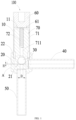
FIG. 1 is a schematic view of an electromagnetic valve according to one or more embodiments. -
FIG. 2 is an enlarged view of portion A of the electromagnetic valve inFIG. 1 . -
FIG. 3 is a schematic view of an air conditioning system according to one or more embodiments. - Reference signs are as follows:
100 represents an electromagnetic valve; 10 represents a valve sleeve; 11 represents a valve cavity; 20 represents a valve body; 21 represents a valve port; 22 represents a mounting hole; 30 represents a spherical sealing member; 40 represents a first connecting pipe; 50 represents a second connecting pipe; 60 represents an attracting member; 61 represents a shunt ring; 70 represents a valve stem component; 71 represents a core iron; 711 represents an inner hole; 72 represents a reset spring; and 200 represents an air conditioning system. - The technical scheme in the embodiment of this application will be described clearly and completely with the attached drawings. Obviously, the described embodiment is only a part of the embodiment of this application, not the whole embodiment. Based on the embodiments in this application, all other embodiments obtained by ordinary technicians in this field without creative work belong to the protection scope of this application.
- It should be noted that when a component is considered to be "mounted" on another component, it can be directly on the other component or there can be a component in the middle. When a component is considered to be "set on" another component, it can be directly set on another component or there may be intervening components at the same time. When a component is considered to be "fixed" to another component, it can be directly fixed to another component or there may be intervening components at the same time.
- Unless otherwise defined, all technical and scientific terms used herein have the same meaning as commonly understood by those skilled in the technical field of this application. The terminology used herein in the specification of this application is only for the purpose of describing specific embodiments, and is not intended to limit this application. As used herein, the term "or/and" includes any and all combinations of one or more related listed items.
- Referring to
FIG. 1 to FIG. 2 , theelectromagnetic valve 100 is industrial equipment controlled by electromagnetism, an automatic basic element for controlling fluid, belonging to actuators, and not limited to a hydraulic actuator and a pneumatic actuator. Theelectromagnetic valve 100 is used in industrial control system to adjust a direction, a flow rate, a speed and other parameters of medium. Theelectromagnetic valve 100 can cooperate with different circuits to achieve an expected control, and a control accuracy and flexibility can be guaranteed. - In the related art, under a condition of low temperature and high pressure, a refrigerant is too thick, which leads to an inconvenience of refrigerant passing through the valve port, which increases the valve opening time and affects the working efficiency of the electromagnetic valve.
- In order to solve problems existing in the electromagnetic valve in the related art, the present disclosure provides an
electromagnetic valve 100 including a valve sleeve 10and avalve body 20. Thevalve sleep 10 is fixedly connected with thevalve body 20, and thevalve sleep 10 can be inserted into thevalve body 20 or sleeved outside thevalve body 20. Avalve cavity 11 is formed by enclosing an interior of the valve sleeve and an interior of the valve body. Aspherical sealing member 30 is disposed in thevalve cavity 11, thevalve body 20 is provided with thevalve port 21, and thespherical sealing member 30 is capable of moving in thevalve cavity 11 along an axis of thevalve sleeve 10 and opening or sealing thevalve port 21. A first connectingpipe 40 is fixedly connected to a side wall of thevalve body 20, the first connectingpipe 40 is in communication with thevalve cavity 11, and thevalve body 20 is fixedly connected with the second connectingpipe 50 extending along an axis of thevalve body 21, the second connectingpipe 50 is in communication with thevalve port 21. - In some embodiments, an axis of the first connecting
pipe 40 is flush or substantially flush with an end of thevalve port 21 towards thespherical sealing member 30. Specifically, the axis of the first connectingpipe 40 can be flush with an end of thevalve port 21 towards thespherical sealing member 30. The axis of the first connectingpipe 40 can also be separated from an end of thevalve port 21 towards thespherical sealing member 30 by a preset distance, so that the refrigerant can flow out through thevalve port 21 more easily, especially at low temperature and low pressure, viscous refrigerants flow out of thevalve port 21 more easily, which increases a valve opening speed of thevalve port 21 and improves a working efficiency of theelectromagnetic valve 100. - In some embodiments, in a direction perpendicular to the axis of the first connecting pipe 40 (i.e., the axis of the valve body 20), a position of the axis of the first connecting
pipe 40 is not lower than a position of the end of thevalve port 21 towards thespherical sealing member 30. Specifically, the axis of the first connectingpipe 40 can be flush with the end of thevalve port 21 towards thespherical sealing member 30. Alternatively, the axis of the first connectingpipe 40 may be arranged away from the second connectingpipe 50 relative to thevalve port 21 towards thespherical sealing member 30, that is, as shown inFIG. 1 , a position of the axis of the first connectingpipe 40 not lower than a position of an upper end surface of thevalve port 21 along the axis of thevalve body 20. Of course, this is only an example, and cannot be regarded as a limitation of the present disclosure. - It should be noted that in the present disclosure, by the axis of the first connecting
pipe 40 being flush with the end of thevalve port 21 towards thespherical sealing member 30, it is easier for the refrigerant to flow out through thevalve port 21. Alternatively, comparing with the end of thevalve port 21 towards thespherical sealing member 30, the axis of the first connectingpipe 40 being arranged away from the second connectingpipe 50, it is easier for the refrigerant to flow out through thevalve port 21, especially, the refrigerant with high viscosity flows out from thevalve port 21 at low temperature and low pressure. Thereby, the valve opening speed of thevalve port 21 is increased and the working efficiency of theelectromagnetic valve 100 is improved. - In some embodiments, a distance between the axis of the first connecting
pipe 40 and thevalve port 21 is defined as H, and the distance H of the first connectingpipe 40 and thevalve port 21 satisfies the following relationship: 0 mm ≤ H ≤ 5 mm. - It is worth noting that if a position of the
valve port 21 is too lower, the distance H between the axis of the first connectingpipe 40 and thevalve port 21 will be greater, and it is undoubtedly necessary to increase a length of other components in thevalve sleeve 10. If the distance H between the axis of the first connectingpipe 40 and thevalve port 21 is too great, a material cost of theelectromagnetic valve 100 will increase, therefore, considering the above-mentioned, the distance between the axis of the first connectingpipe 40 and thevalve port 21 is 0 mm ≤ H ≤ 5 mm, thus avoiding the material cost increase of theelectromagnetic valve 100 caused by an excessively high distance H between the axis of the first connectingpipe 40 and thevalve port 21. - Referring to
FIG. 1 , in an embodiment, thevalve body 20 is provided with a mountinghole 22 for installing thevalve sleep 10 in a direction of thevalve sleep 10, and an end of thevalve sleep 10 extends into the mountinghole 22 and is welded and fixed with thevalve body 20. - In this embodiment, the
valve sleeve 10 is a generally cylindrical structure, and thevalve body 20 is a generally stepped cylindrical structure. Of course, thevalve sleep 10 is not limited to a cylindrical structure, and thevalve body 20 is not limited to a stepped cylindrical structure. In other embodiments, thevalve sleep 10 and thevalve body 20 can also be arranged in a square cylindrical structure, which is not limited here. - Furthermore, an attracting
member 60 and avalve stem component 70 are arranged in thevalve sleeve 10, and the attractingmember 60 is fixed at an end of thevalve sleeve 10 away from thevalve port 21, thevalve stem component 70 is arranged at an end of thevalve sleeve 10 adjacent to thevalve port 21, and thevalve stem component 70 is capable of moving towards the attractingmember 60 under an attraction of the attractingmember 60. - Specifically, the
valve stem component 70 includes acore iron 71 and areset spring 72. Aninner hole 711 is disposed in a center of thecore iron 71, and theinner hole 711 penetrates through thecore iron 71 and is a stepped hole. And thereset spring 72 is disposed in theinner hole 711, one end of thereset spring 72 abuts against the attractingmember 60, and the other end of thereset spring 72 is accommodated in theinner hole 711 of thecore iron 71. Thespherical sealing member 30 is fixedly connected to an end of thecore iron 71 away from the attractingmember 60. Under an action of the attractingmember 60, thecore iron 71 can move towards or away from the attractingmember 60 and cause thespherical sealing member 30 to move, such that thespherical sealing member 30 abuts against or separates from thevalve port 21 to close or open thevalve port 21. - A coil (not shown in the figure) is sleeved on an outer wall of the
valve sleeve 10. When the coil is not energized, under an elastic force of thereset spring 72, thecore iron 71 is pushed towards thevalve body 20, and thespherical sealing member 30 abuts against thevalve port 21 to achieve sealing. At this time, thevalve port 21 is sealed, and the refrigerants in the first connectingpipe 40 and the second connectingpipe 50 are not in communication with each other. When the coil is energized, under an action of electromagnetic field, a magnetic attraction force is generated between thecore iron 71 and the attractingmember 60, and thecore iron 71 overcomes an elastic force of thereset spring 72 and moves towards the attractingmember 60. Thespherical sealing member 30 is separated from thevalve port 21, thevalve port 21 is opened, and the refrigerant flows into the second connectingpipe 50 from the first connectingpipe 40 through thevalve port 21. - Furthermore, an end of the attracting
member 60 adjacent to thecore iron 71 is fixedly provided with theshunt ring 61. Thecore iron 71 can move towards the attractingmember 60 and abuts against theshunt ring 61. - It should be noted that since the
electromagnetic valve 100 is in operation, thecore iron 71 will be continuously attracted by the attractingmember 60, move towards the attractingmember 60 and abut against the attractingmember 60, therefore, in order to reduce a noise generated by theelectromagnetic valve 100 in an operating process, in this embodiment, theshunt ring 61 which is capable of abutting against thecore iron 71 is arranged on the attractingmember 60, so as to achieve an effect of reducing the noise generated by theelectromagnetic valve 100 in the operating process. - Furthermore, a size of the
valve port 21 is defined as D, and the size D of thevalve port 21 satisfies the following relationship: 1 mm ≤ D ≤ 2.5 mm. The size D of thevalve port 21 is too great, which will lead to a poor sealing performance of thespherical sealing member 30 when it is plugged in thevalve port 21. If the size D of thevalve port 21 is too small, a circulation of refrigerant will not be guaranteed, so to avoid the above mentioned phenomena, it is necessary to limit the size D of thevalve port 21 to a suitable range of greater than or equal to 1 mm and less than or equal to 2.5 mm. - Of course, in other embodiments, the size D of the
valve port 21 can be adjusted as required, and is not limited here. - In some embodiments, a material of the
spherical sealing member 30 is different from a material of thevalve body 20. Since thespherical sealing member 30 moves in the direction of thevalve port 21 and abuts against thevalve port 21 during the operation process of theelectromagnetic valve 100, if thespherical sealing member 30 and thevalve body 20 are made of same material, thespherical sealing member 30 and thevalve body 20 are prone to wear and tear during contact, resulting in loss, thus affecting a sealing performance of thespherical sealing member 30 abutting against thevalve port 21. Therefore, to avoid the above mentioned phenomena, in this embodiment, thespherical sealing member 30 and thevalve body 20 are made of different materials, so that when thespherical sealing member 30 abuts on thevalve body 20, an abrasion between thespherical sealing member 30 and thevalve body 20 is reduced, thereby enhancing the sealing performance of thespherical sealing member 30 abutting against thevalve port 21. - In this embodiment, the
spherical sealing member 30 is a steel ball. In this way, thevalve body 20 should be made of materials other than steel. Of course, in other embodiments, thespherical sealing member 30 can also be made of other materials such as aluminum, which is not limited here. - In an embodiment, the
valve sleeve 10 is a stainless steel sleeve, and the first connectingpipe 40 and both the second connectingpipe 50 are copper pipes. Of course, in other embodiments, thevalve sleeve 10, the first connectingpipe 40 and the second connectingpipe 50 can also be made of other materials such as aluminum, which is not limited here. - It should be noted that in this embodiment, referring to
FIG. 1 , for example, theelectromagnetic valve 100 is set to be installed vertically, the first connectingpipe 40 as an inlet pipe, and the second connectingpipe 50 as an outlet pipe. taking this arrangement as an example, a circulation process of theelectromagnetic valve 100 is briefly described. - During the operation process of the
electromagnetic valve 100, when thevalve port 21 is opened, the refrigerant flows into theelectromagnetic valve 100 from the first connectingpipe 40. Most of the refrigerant can flow directly downward into thevalve port 21 and then flow into the second connectingpipe 50 through thevalve port 21. Referring toFIG. 1 , the position of the axis of the first connectingpipe 40 not lower than the position of the upper end face of thevalve port 21 along the axis of thevalve body 20, so that the refrigerant in the first connectingpipe 40 can smoothly and quickly flow into thevalve port 21. It reduces a resistance and time required for viscous refrigerant when flowing through thevalve port 21 at low temperature and low pressure, thus improving the working efficiency of theelectromagnetic valve 100. - The present disclosure further provides an
air conditioning system 200 including the aboveelectromagnetic valve 100 provided. - The technical features of the above-mentioned embodiments can be combined arbitrarily. In order to make the description concise, not all possible combinations of the technical features are described in the embodiments. However, as long as there is no contradiction in the combination of these technical features, the combinations should be considered as in the scope of the present disclosure.
- One of ordinary skill in the art should recognize that the above embodiments are used only to illustrate the present disclosure and are not used to limit the present disclosure, and that appropriate variations and improvements to the above embodiments fall within the protection scope of the present disclosure so long as they are made without departing from the substantial spirit of the present disclosure.
Claims (11)
- An electromagnetic valve, comprising a valve sleeve and a valve body, wherein the valve sleeve is fixedly connected with the valve body; a valve cavity is formed by enclosing an interior of the valve sleeve and an interior of the valve body, and a spherical sealing member is disposed in the valve cavity; the valve body is provided with a valve port, and the spherical sealing member is capable of moving in the valve cavity along an axis of the valve sleeve and opening or sealing the valve port;characterized in that a first connecting pipe is fixedly connected to a side wall of the valve body, the first connecting pipe is in communication with the valve cavity, the valve body is fixedly connected with a second connecting pipe extending along an axis of the valve body, the second connecting pipe is in communication with the valve port, and an axis of the first connecting pipe is flush with an end of the valve port towards the spherical sealing member;or, an axis of the first connecting pipe is arranged away from the second connecting pipe relative to an end of the valve port towards the spherical sealing member.
- The electromagnetic valve of claim 1, wherein a distance between the axis of the first connecting pipe and the valve port is defined as H, and the distance H between the axis of the first connecting pipe and the valve port satisfies the following relationship: 0 mm ≤ H ≤ 5 mm.
- The electromagnetic valve of claim 1, wherein a size of the valve port is defined as D and the size D of the valve port satisfies the following relationship: 1 mm ≤ D ≤ 2.5 mm.
- The electromagnetic valve of claim 1, wherein a material of the spherical sealing member is different from a material of the valve body.
- The electromagnetic valve of claims 1 or 4, wherein the spherical sealing member is a steel ball.
- The electromagnetic valve of claim 1, wherein an attracting member and a valve stem component are arranged in the valve cavity, and the attracting member is fixed at an end of the valve sleeve away from the valve port, the valve stem component is arranged at an end of the valve sleeve adjacent to the valve port, and the valve stem component is capable of moving towards the attracting member under an attraction of the attracting member;
the valve stem component is connected with the spherical sealing member, and the valve stem component is capable of sliding in the valve cavity to cause the spherical sealing member to open/seal the valve port. - The electromagnetic valve of claim 6, wherein the valve stem component comprises a core iron and a reset spring, one end of the reset spring abuts against the attracting member, the other end of the reset spring is disposed in the core iron, and the core iron is capable of moving towards or away from the attracting member to cause the spherical sealing member to move.
- The electromagnetic valve of claim 7, wherein a shunt ring is fixed to the end of the attracting member adjacent to the core iron, and the core iron is capable of moving towards the attracting member and abuts against the shunt ring.
- The electromagnetic valve of claim 1, wherein the valve sleeve is a stainless steel sleeve, and both the first connecting pipe and the second connecting pipe are copper pipes.
- An air conditioning system, characterized by comprising the electromagnetic valve of any one of claims 1 to 9.
- An electromagnetic valve, comprising a valve sleeve and a valve body, wherein the valve sleeve is fixedly connected with the valve body; a valve cavity is formed by enclosing an interior of the valve sleeve and an interior of the valve body, and a spherical sealing member is disposed in the valve cavity; the valve body is provided with a valve port, and the spherical sealing member is capable of moving in the valve cavity along an axis of the valve sleeve and opening or sealing the valve port;
characterized in that a first connecting pipe is fixedly connected to a side wall of the valve body, the first connecting pipe is in communication with the valve cavity, the valve body is fixedly connected with a second connecting pipe extending along an axis of the valve body, the second connecting pipe is in communication with the valve port, and an axis of the first connecting pipe is flush or substantially flush with an end of the valve port towards the spherical sealing member.
Applications Claiming Priority (2)
| Application Number | Priority Date | Filing Date | Title |
|---|---|---|---|
| CN202122391299.6U CN215981078U (en) | 2021-09-29 | 2021-09-29 | Electromagnetic valve and air conditioning system with same |
| PCT/CN2022/118995 WO2023051263A1 (en) | 2021-09-29 | 2022-09-15 | Electromagnetic valve and air conditioning system having same |
Publications (2)
| Publication Number | Publication Date |
|---|---|
| EP4390197A1 true EP4390197A1 (en) | 2024-06-26 |
| EP4390197A4 EP4390197A4 (en) | 2024-12-04 |
Family
ID=80570176
Family Applications (1)
| Application Number | Title | Priority Date | Filing Date |
|---|---|---|---|
| EP22874650.9A Pending EP4390197A4 (en) | 2021-09-29 | 2022-09-15 | ELECTROMAGNETIC VALVE AND AIR CONDITIONING |
Country Status (6)
| Country | Link |
|---|---|
| US (1) | US12510163B2 (en) |
| EP (1) | EP4390197A4 (en) |
| JP (1) | JP7756234B2 (en) |
| KR (1) | KR102916423B1 (en) |
| CN (1) | CN215981078U (en) |
| WO (1) | WO2023051263A1 (en) |
Families Citing this family (3)
| Publication number | Priority date | Publication date | Assignee | Title |
|---|---|---|---|---|
| CN215981078U (en) * | 2021-09-29 | 2022-03-08 | 浙江盾安机械有限公司 | Electromagnetic valve and air conditioning system with same |
| CN115163862B (en) * | 2022-05-23 | 2025-11-18 | 博格华纳汽车零部件(天津)有限公司 | A sealing structure for a solenoid valve, a solenoid valve, an accumulator, and an automobile. |
| CN222994812U (en) * | 2023-05-30 | 2025-06-17 | 台湾东电化股份有限公司 | Optical element driving mechanism |
Family Cites Families (15)
| Publication number | Priority date | Publication date | Assignee | Title |
|---|---|---|---|---|
| JPS5794771U (en) * | 1980-12-02 | 1982-06-10 | ||
| EP0689015A1 (en) * | 1994-06-21 | 1995-12-27 | Staefa Control System Scs Ag | Control valve with actuating drive |
| JP2002250457A (en) * | 2001-02-23 | 2002-09-06 | Saginomiya Seisakusho Inc | Latch type solenoid valve and four-way switching valve and latch type solenoid coil therefor |
| JP4812199B2 (en) * | 2001-08-29 | 2011-11-09 | 株式会社不二工機 | solenoid valve |
| JP2004084885A (en) * | 2002-08-28 | 2004-03-18 | Saginomiya Seisakusho Inc | Solenoid valve and its assembly method |
| JP2004239348A (en) * | 2003-02-06 | 2004-08-26 | Fuji Koki Corp | Solenoid valve |
| JP2006189115A (en) * | 2005-01-07 | 2006-07-20 | Tgk Co Ltd | Control valve attachment structure |
| DE102006062350A1 (en) * | 2006-12-22 | 2008-06-26 | Alfred Kärcher Gmbh & Co. Kg | Dispensing device for water dispensing apparatus, has valve device with valve seat for forming flow diverting unit, which changes flow direction of water around ninety degree, where water flows from inlets to outlet of dispensing body |
| CN101737545B (en) * | 2008-11-06 | 2012-08-08 | 浙江三花股份有限公司 | Electromagnetic valve and processing method thereof |
| CN101806366B (en) * | 2009-07-05 | 2011-10-19 | 浙江三花股份有限公司 | Electromagnetic valve |
| CN102606788B (en) * | 2011-01-20 | 2015-07-01 | 浙江三花股份有限公司 | Electromagnetic valve |
| CN102619991A (en) * | 2011-01-30 | 2012-08-01 | 浙江三花股份有限公司 | Refrigeration system and electromagnetic valve of refrigeration system |
| CN107035909B (en) * | 2016-02-03 | 2019-09-10 | 浙江三花制冷集团有限公司 | a solenoid valve |
| CN113251157B (en) * | 2020-01-28 | 2025-10-17 | 株式会社不二工机 | Electrically actuated valve and method for manufacturing the same |
| CN215981078U (en) * | 2021-09-29 | 2022-03-08 | 浙江盾安机械有限公司 | Electromagnetic valve and air conditioning system with same |
-
2021
- 2021-09-29 CN CN202122391299.6U patent/CN215981078U/en active Active
-
2022
- 2022-09-15 JP JP2024503959A patent/JP7756234B2/en active Active
- 2022-09-15 WO PCT/CN2022/118995 patent/WO2023051263A1/en not_active Ceased
- 2022-09-15 EP EP22874650.9A patent/EP4390197A4/en active Pending
- 2022-09-15 KR KR1020247009043A patent/KR102916423B1/en active Active
-
2024
- 2024-03-20 US US18/610,397 patent/US12510163B2/en active Active
Also Published As
| Publication number | Publication date |
|---|---|
| JP7756234B2 (en) | 2025-10-17 |
| US20240263707A1 (en) | 2024-08-08 |
| US12510163B2 (en) | 2025-12-30 |
| KR102916423B1 (en) | 2026-01-23 |
| JP2024532063A (en) | 2024-09-05 |
| EP4390197A4 (en) | 2024-12-04 |
| WO2023051263A1 (en) | 2023-04-06 |
| KR20240042161A (en) | 2024-04-01 |
| CN215981078U (en) | 2022-03-08 |
Similar Documents
| Publication | Publication Date | Title |
|---|---|---|
| EP4390197A1 (en) | Electromagnetic valve and air conditioning system having same | |
| CN102444739B (en) | Electric valve | |
| JP6194157B2 (en) | Motorized valve | |
| KR20000077185A (en) | Expansion valve | |
| EP4368861A1 (en) | Electromagnetic valve and air conditioning system provided with same | |
| EP0222223A1 (en) | Inline solenoid operated slide valve | |
| CN101988583B (en) | Magnetic valve | |
| JP2006528311A (en) | Solenoid valve with damping disk to attenuate noise | |
| EP4446634A1 (en) | Solenoid valve and air conditioning system having same | |
| CN216742840U (en) | Electromagnetic valve and air conditioning system with same | |
| CN117515197A (en) | Electronic expansion valve and refrigeration equipment | |
| CN213685321U (en) | Electromagnetic valve | |
| CN220668420U (en) | Electronic expansion valve and refrigeration system | |
| KR20250139872A (en) | electronic expansion valve | |
| CN115013539B (en) | A full-flow electronic expansion valve | |
| WO2015185437A1 (en) | Solenoid valve | |
| CN212253247U (en) | Air conditioner and throttle valve thereof | |
| CN216743075U (en) | Electromagnetic valve and air conditioning system with same | |
| JP6194403B2 (en) | Motorized valve | |
| CN216112428U (en) | Electromagnetic valve and air conditioning system with same | |
| CN216742880U (en) | Electromagnetic valve | |
| CN115560080A (en) | Solenoid valve and air conditioning equipment | |
| CN111692345A (en) | Electromagnetic valve | |
| CN220134642U (en) | Solenoid valve and air conditioning system | |
| CN223881821U (en) | Electromagnetic valve and electric control system with same |
Legal Events
| Date | Code | Title | Description |
|---|---|---|---|
| STAA | Information on the status of an ep patent application or granted ep patent |
Free format text: STATUS: THE INTERNATIONAL PUBLICATION HAS BEEN MADE |
|
| PUAI | Public reference made under article 153(3) epc to a published international application that has entered the european phase |
Free format text: ORIGINAL CODE: 0009012 |
|
| STAA | Information on the status of an ep patent application or granted ep patent |
Free format text: STATUS: REQUEST FOR EXAMINATION WAS MADE |
|
| 17P | Request for examination filed |
Effective date: 20240321 |
|
| AK | Designated contracting states |
Kind code of ref document: A1 Designated state(s): AL AT BE BG CH CY CZ DE DK EE ES FI FR GB GR HR HU IE IS IT LI LT LU LV MC MK MT NL NO PL PT RO RS SE SI SK SM TR |
|
| A4 | Supplementary search report drawn up and despatched |
Effective date: 20241105 |
|
| RIC1 | Information provided on ipc code assigned before grant |
Ipc: F16K 27/02 20060101ALI20241029BHEP Ipc: F16K 1/14 20060101ALI20241029BHEP Ipc: F16K 31/06 20060101AFI20241029BHEP |
|
| DAV | Request for validation of the european patent (deleted) | ||
| DAX | Request for extension of the european patent (deleted) |